JP2010189251A - Method for manufacturing optical fiber preform - Google Patents
Method for manufacturing optical fiber preformDownload PDFInfo
- Publication number
- JP2010189251A JP2010189251AJP2009120731AJP2009120731AJP2010189251AJP 2010189251 AJP2010189251 AJP 2010189251AJP 2009120731 AJP2009120731 AJP 2009120731AJP 2009120731 AJP2009120731 AJP 2009120731AJP 2010189251 AJP2010189251 AJP 2010189251A
- Authority
- JP
- Japan
- Prior art keywords
- optical fiber
- core tube
- fiber porous
- preform
- porous preform
- Prior art date
- Legal status (The legal status is an assumption and is not a legal conclusion. Google has not performed a legal analysis and makes no representation as to the accuracy of the status listed.)
- Granted
Links
Images

Classifications
- C—CHEMISTRY; METALLURGY
- C03—GLASS; MINERAL OR SLAG WOOL
- C03B—MANUFACTURE, SHAPING, OR SUPPLEMENTARY PROCESSES
- C03B37/00—Manufacture or treatment of flakes, fibres, or filaments from softened glass, minerals, or slags
- C03B37/01—Manufacture of glass fibres or filaments
- C03B37/012—Manufacture of preforms for drawing fibres or filaments
- C03B37/014—Manufacture of preforms for drawing fibres or filaments made entirely or partially by chemical means, e.g. vapour phase deposition of bulk porous glass either by outside vapour deposition [OVD], or by outside vapour phase oxidation [OVPO] or by vapour axial deposition [VAD]
- C03B37/01446—Thermal after-treatment of preforms, e.g. dehydrating, consolidating, sintering
Landscapes
- Chemical & Material Sciences (AREA)
- Engineering & Computer Science (AREA)
- Chemical Kinetics & Catalysis (AREA)
- Physics & Mathematics (AREA)
- General Chemical & Material Sciences (AREA)
- Life Sciences & Earth Sciences (AREA)
- Thermal Sciences (AREA)
- General Life Sciences & Earth Sciences (AREA)
- Geochemistry & Mineralogy (AREA)
- Manufacturing & Machinery (AREA)
- Materials Engineering (AREA)
- Organic Chemistry (AREA)
- Manufacture, Treatment Of Glass Fibers (AREA)
Abstract
Translated fromJapaneseDescription
Translated fromJapanese本発明は、光ファイバ母材の製造方法に関するものであり、より具体的には、コアを含む光ファイバ多孔質母材を脱水、焼結する方法に関するものである。 The present invention relates to a method for manufacturing an optical fiber preform, and more specifically to a method for dehydrating and sintering an optical fiber porous preform including a core.
従来、光ファイバ多孔質母材の脱水および焼結は、支持棒に把持された光ファイバ多孔質母材を収容する炉心管と、この炉心管の外周に配設されたヒータとを備えた脱水焼結装置を用いて行われている。炉心管の下部にはガス供給口が設けられ、ガス供給口からは不活性ガス等の光ファイバ多孔質母材を脱水焼結するのに必要なガスが供給される。一方、炉心管の上部にはガス排気管が設けられ、ガス供給口から供給されたガスが排出される。そして、支持棒に把持された光ファイバ多孔質母材は、炉心管内で回転しながら降下させられ、ヒータによる加熱領域を通過することで脱水および焼結される。
なお、脱水および焼結の方法として、光ファイバ多孔質母材を900℃〜1300℃の温度に設定された加熱領域を通過させて脱水し、脱水した光ファイバ多孔質母材を炉心管内の所定位置まで一旦引き上げた後、再び1400℃〜1600℃の温度に設定された加熱領域を通過させて焼結させる、2段ガラス化が一般的に行われている。Conventionally, dehydration and sintering of an optical fiber porous preform is performed by dehydrating a furnace core tube containing the optical fiber porous preform held by a support rod and a heater disposed on the outer periphery of the furnace core tube. This is done using a sintering machine. A gas supply port is provided in the lower part of the furnace core tube, and a gas necessary for dehydrating and sintering the optical fiber porous preform such as an inert gas is supplied from the gas supply port. On the other hand, a gas exhaust pipe is provided in the upper part of the core tube, and the gas supplied from the gas supply port is discharged. Then, the optical fiber porous preform held by the support rod is lowered while rotating in the furnace core tube, and dehydrated and sintered by passing through a heating region by a heater.
In addition, as a method of dehydration and sintering, the optical fiber porous preform is dehydrated by passing through a heating region set at a temperature of 900 ° C. to 1300 ° C., and the dehydrated optical fiber porous preform is predetermined in the furnace core tube. A two-stage vitrification is generally performed in which the glass is once pulled up to a position and then passed again through a heating region set to a temperature of 1400 ° C. to 1600 ° C. for sintering.
ところで、前記光ファイバ多孔質母材の脱水焼結に使用される脱水焼結装置において、炉心管内が負圧になると外気が流入して光ファイバ多孔質母材に不純物が混入することがあり、得られる光ファイバの伝送損失が悪化することがある。そこで、脱水焼結処理工程では、炉心管の内圧を外部より一定圧力だけ高く(通常、数十Pa程度)保持させるように圧力制御されている。 By the way, in the dehydration and sintering apparatus used for dehydration and sintering of the optical fiber porous preform, impurities may be mixed into the optical fiber porous preform due to the flow of outside air when the pressure inside the furnace tube becomes negative. The transmission loss of the obtained optical fiber may deteriorate. Therefore, in the dehydration and sintering process, the pressure is controlled so that the internal pressure of the core tube is kept higher than the outside by a certain pressure (usually about several tens of Pa).
また、炉心管内の圧力変動は、光ファイバ多孔質母材の外径と炉心管の内径との比が小さい場合、あるいは炉心管内で光ファイバ多孔質母材が上下移動する場合に、特に顕著になることが知られている。そこで、光ファイバ母材の脱水焼結方法として、炉心管の内径と光ファイバ多孔質母材の外径との比率を1.5以上とすることにより、炉心管内の差圧変動を抑制し、外気の流入や炉内ガスの流出を防止する方法が開示されている(特許文献1参照)。 The pressure fluctuation in the core tube is particularly noticeable when the ratio of the outer diameter of the optical fiber porous preform to the inner diameter of the reactor core tube is small, or when the optical fiber porous preform moves up and down in the reactor core tube. It is known to be. Therefore, as a dehydration sintering method of the optical fiber preform, by controlling the ratio of the inner diameter of the core tube and the outer diameter of the optical fiber porous preform to 1.5 or more, to suppress the differential pressure fluctuation in the core tube, A method for preventing inflow of outside air and outflow of gas in the furnace is disclosed (see Patent Document 1).
近年、製造コストを低減するために光ファイバ母材は大型化が図られている。しかしながら、上記の方法により炉心管内の差圧変動を抑制するために、炉心管の内径と光ファイバ多孔質母材の外径との比率を1.5以上とするには、炉心管の内径を非常に大きくする必要がある。また、上記の方法では、光ファイバ多孔質母材の外径に対する炉心管の内径の比率により、製造できる母材の大きさが制限され、供給するガス量に対して小さい光ファイバ母材しか製造できないことになり、製造効率が悪いという問題がある。 In recent years, the size of optical fiber preforms has been increased in order to reduce manufacturing costs. However, in order to suppress the differential pressure fluctuation in the core tube by the above method, in order to set the ratio of the inner diameter of the core tube and the outer diameter of the optical fiber porous preform to 1.5 or more, the inner diameter of the core tube is reduced. It needs to be very large. In the above method, the ratio of the inner diameter of the core tube to the outer diameter of the porous optical fiber preform is limited, and the size of the preform that can be manufactured is limited. There is a problem that production efficiency is poor.
本発明は、前述した課題を解決するためにされたものであって、光ファイバ多孔質母材の外径と炉心管の内径との比に影響を受けることなく、伝送損失特性の安定した光ファイバを得られ、さらに、製造効率がよい光ファイバ母材の製造方法を提供することを目的とする。 The present invention has been made to solve the above-described problems, and is an optical fiber having stable transmission loss characteristics without being affected by the ratio between the outer diameter of the optical fiber porous preform and the inner diameter of the core tube. An object of the present invention is to provide a method for producing an optical fiber preform, which can obtain a fiber and has high production efficiency.
上記目的を達成するために本発明は、光ファイバ多孔質母材を炉心管に収容し、前記炉心管内に下方からガスを供給しながら前記光ファイバ多孔質母材を加熱して脱水および焼結を行う光ファイバ母材の製造方法であって、前記光ファイバ多孔質母材を前記炉心管内で降下させて加熱領域を通過させることにより、前記光ファイバ多孔質母材を脱水する脱水工程と、脱水した前記光ファイバ多孔質母材を所定位置まで引き上げる切替工程と、引き上げた前記光ファイバ多孔質母材を再び降下させて前記脱水工程における加熱領域温度よりも高い温度に設定された加熱領域を通過させることにより、前記光ファイバ多孔質母材を焼結する焼結工程と、を含み、前記切替工程における前記光ファイバ多孔質母材の引き上げ速度をA[mm/分]、前記炉心管内を流れる常温での前記ガスの流速をB[mm/分]としたとき、A≦Bを満たすことを特徴とする。 In order to achieve the above-mentioned object, the present invention is to dewater and sinter an optical fiber porous preform by housing the optical fiber porous preform in a furnace core tube and heating the optical fiber porous preform while supplying gas from below into the furnace core tube. A dehydrating step of dehydrating the optical fiber porous preform by lowering the optical fiber porous preform in the furnace core tube and passing it through a heating region, and A switching step of pulling up the dehydrated optical fiber porous preform to a predetermined position; and a heating region set to a temperature higher than the heating region temperature in the dehydration step by lowering the pulled-up optical fiber porous preform again. A sintering step of sintering the optical fiber porous preform by passing, and the pulling speed of the optical fiber porous preform in the switching step is A [mm / min], When the flow velocity of the gas at normal temperature through the serial core tube was B [mm / min], and satisfies the A ≦ B.
前記切替工程における前記光ファイバ多孔質母材の引き上げ速度をA[mm/分]、前記炉心管内を流れる常温での前記ガスの流速をB[mm/分]としたとき、1.5×A≦Bを満たすことを特徴とする。 When the pulling speed of the optical fiber porous preform in the switching step is A [mm / min] and the flow rate of the gas flowing in the furnace tube at room temperature is B [mm / min], 1.5 × A ≦ B is satisfied.
前記切替工程において前記炉心管に供給するガス流量をC[L/分]、前記脱水工程において前記炉心管に供給するガス流量をD[L/分]としたとき、C>Dを満たすことを特徴とする。 When the gas flow rate supplied to the core tube in the switching step is C [L / min] and the gas flow rate supplied to the core tube in the dehydration step is D [L / min], C> D is satisfied. Features.
本発明の光ファイバ母材の製造方法によれば、光ファイバ多孔質母材の外径と炉心管の内径との比が小さい場合であっても伝送損失特性の安定した光ファイバを得ることができ、製造効率よく光ファイバ母材を製造することができる。 According to the method for manufacturing an optical fiber preform of the present invention, an optical fiber having a stable transmission loss characteristic can be obtained even when the ratio of the outer diameter of the porous optical fiber preform to the inner diameter of the core tube is small. The optical fiber preform can be manufactured with high manufacturing efficiency.
以下、本発明の実施の形態による光ファイバ母材の製造方法について説明する。 Hereinafter, a method for manufacturing an optical fiber preform according to an embodiment of the present invention will be described.
(実施の形態)
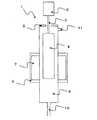
まず、本実施の形態にて用いる脱水焼結装置と光ファイバ多孔質母材について説明する。図1は、本実施の形態にて用いる脱水焼結装置および光ファイバ多孔質母材4の断面概略図を示すものである。
脱水焼結装置1は、回転昇降装置2に支持棒3を介して保持された光ファイバ多孔質母材4を収容する上蓋5を有する石英ガラス製の炉心管6と、炉心管6の外周に備えられ外部から光ファイバ多孔質母材4を加熱するヒータ7と、炉心管6の外周で断熱材を介してヒータ7を収容している炉体9とを備えている。(Embodiment)
First, the dehydration sintering apparatus and the optical fiber porous preform used in the present embodiment will be described. FIG. 1 is a schematic cross-sectional view of a dehydration sintering apparatus and an optical fiber porous preform 4 used in the present embodiment.
The dehydration sintering apparatus 1 includes a quartz glass core tube 6 having an upper cover 5 that accommodates an optical fiber porous base material 4 held by a rotary lifting device 2 via a support rod 3, and an outer periphery of the core tube 6. A
なお、炉心管6は、ヘリウムガスなどの不活性ガスをはじめとする、脱水、焼結に必要なガスを炉心管6内に供給するためのガス供給口10を下部に、炉内ガスを炉心管6外に排出するためのガス排出口11を上部に備える。 The core tube 6 has a
また、光ファイバ多孔質母材4は、VAD法などを用いて合成されたものであり、中心軸に形成されたコア部とその外周を覆うクラッド部とを有する。なお、コア部を含む光ファイバ多孔質母材4を脱水焼結して形成されるガラスロッドをコアロッドと呼ぶ。 The optical fiber porous preform 4 is synthesized using a VAD method or the like, and has a core portion formed on the central axis and a clad portion covering the outer periphery thereof. A glass rod formed by dehydrating and sintering the optical fiber porous preform 4 including the core portion is referred to as a core rod.
次に、図1に示す脱水焼結装置1を用いて、コア部を含む光ファイバ多孔質母材4を脱水焼結し、コアロッドを製造する方法について詳細に説明する。本発明の光ファイバ母材の製造方法にかかるコアロッドの製造方法は、脱水工程、切替工程、焼結工程の3工程を有する。まず、脱水工程について説明する。 Next, a method for producing a core rod by dehydrating and sintering the optical fiber porous preform 4 including the core portion using the dehydrating and sintering apparatus 1 shown in FIG. 1 will be described in detail. The manufacturing method of the core rod according to the manufacturing method of the optical fiber preform of the present invention has three steps of a dehydration step, a switching step, and a sintering step. First, the dehydration process will be described.
(脱水工程)
一端を光ファイバ多孔質母材4の上端に接続された支持棒3を回転昇降装置2の保持部で保持する。そして、光ファイバ多孔質母材4を炉心管6内に挿入し、上蓋5により蓋をする。次に、光ファイバ多孔質母材4を所定のスタート位置にセットし、ヒータ7を所定の温度まで昇温する。(Dehydration process)
The support rod 3 having one end connected to the upper end of the optical fiber porous preform 4 is held by the holding unit of the rotary lifting device 2. Then, the optical fiber porous preform 4 is inserted into the core tube 6 and covered with the upper lid 5. Next, the optical fiber porous preform 4 is set at a predetermined start position, and the
ヒータ7の温度は、炉心管6内の最高温度が所定の処理温度となるように調整される。処理温度は、一般的には900℃〜1300℃である。 The temperature of the
また、ガス供給口10から炉心管6内にヘリウムガスと塩素ガスとを含む脱水に必要なガスを供給する。そして、光ファイバ多孔質母材4を回転昇降装置2により回転させながら所定の速度で降下させる。なお、上述した脱水工程は一般的に行われているものと同様である。 A gas necessary for dehydration including helium gas and chlorine gas is supplied from the
(切替工程)
次に、切替工程について説明する。光ファイバ多孔質母材4の上端部が加熱領域を通過して上端部が十分に加熱された時点で、光ファイバ多孔質母材4を回転昇降装置2により引き上げ、ほぼスタート位置の高さまで戻す。このとき、ヒータ7の温度は、脱水工程における温度とほぼ同じであり、ガス供給口10からは炉心管6内にヘリウムガス等のガスを供給する。また、このときの光ファイバ多孔質母材4の引き上げ速度をA[mm/分]、炉心管6内を流れる常温でのガスの流速をB[mm/分]としたとき、A≦Bを満たすように光ファイバ多孔質母材4の引き上げ速度Aおよび炉心管6内を流れる常温でのガス流速Bを設定する。これにより、得られる光ファイバの伝送損失特性を安定化することができる。さらに好ましくは、1.5×A≦Bを満たすAおよびBを設定する。これにより、得られる光ファイバの伝送損失特性のさらなる安定化を図ることができる。(Switching process)
Next, the switching process will be described. When the upper end portion of the optical fiber porous preform 4 passes through the heating region and the upper end portion is sufficiently heated, the optical fiber porous preform 4 is pulled up by the rotary elevating device 2 and returned to almost the height of the start position. . At this time, the temperature of the
なお、ここで炉心管6内を流れるガスの流速Bは、以下のように算出する。
ガスの流速B(mm/分)=(炉心管に供給するガス流量(L/分)×1000)/炉心管6の断面積(cm2)×10Here, the flow velocity B of the gas flowing in the core tube 6 is calculated as follows.
Gas flow rate B (mm / min) = (gas flow rate supplied to the core tube (L / min) × 1000) / cross-sectional area of the core tube 6 (cm 2) × 10
上記に示すように、炉心管6内を流れるガスの流速Bは、常温でのガスの流速を採用している。実際の切替工程での炉心管6内は数百℃〜1300℃の温度分布を有するため、ガスの膨張、収縮の影響もあり、炉心管6内を流れるガスは、複雑な乱流になっている。したがって、実際のガスの流速を検証するのは困難であるため、常温でのガスの流速を採用している。
本発明においては、炉心管6内を流れる常温でのガスの流速Bをパラメータの1つとして採用し、得られる光ファイバの伝送損失特性との関係を見出したものである。As described above, the flow rate B of the gas flowing in the core tube 6 is the normal flow rate of the gas. Since the inside of the core tube 6 in the actual switching process has a temperature distribution of several hundred to 1300 ° C., there is an influence of gas expansion and contraction, and the gas flowing in the core tube 6 becomes a complicated turbulent flow. Yes. Therefore, since it is difficult to verify the actual gas flow rate, the gas flow rate at room temperature is used.
In the present invention, the flow velocity B of the gas at normal temperature flowing through the core tube 6 is adopted as one of the parameters, and the relationship with the transmission loss characteristic of the obtained optical fiber has been found.
(焼結工程)
最後に、焼結工程について説明する。ヒータ7の温度は、炉心管6内の最高温度が所定の処理温度となるように調整される。処理温度は、一般的には1400℃〜1600℃である。次に、ガス供給口10から炉心管6内にヘリウムガス等の焼結に必要なガスを供給する。(Sintering process)
Finally, the sintering process will be described. The temperature of the
そして、光ファイバ多孔質母材4を回転昇降装置2により回転させながら加熱領域に対して所定の速度で降下させ、光ファイバ多孔質母材4を下端から順に加熱領域を通過させて、焼結を行う。なお、上述した焼結工程は一般的に行われているものと同様である。この焼結工程により、光ファイバ多孔質母材4は透明ガラス化され、透明なコアロッドとなる。 Then, the optical fiber porous preform 4 is lowered at a predetermined speed with respect to the heating region while being rotated by the rotary elevating device 2, and the optical fiber porous preform 4 is passed through the heating region in order from the lower end to be sintered. I do. In addition, the sintering process mentioned above is the same as what is generally performed. By this sintering process, the optical fiber porous preform 4 is made into a transparent glass and becomes a transparent core rod.
得られたコアロッドにOVD法、RIT法等の周知の方法でさらなるクラッド付けを行い、所望のコア/クラッド比としたガラス光ファイバ母材とし、これを周知の方法で線引きすることにより、光ファイバが得られる。 The obtained core rod is further clad by a known method such as the OVD method and the RIT method to obtain a glass optical fiber base material having a desired core / cladding ratio, and this is drawn by a known method to obtain an optical fiber. Is obtained.
これまで、光ファイバ多孔質母材4を降下させて加熱領域を通過させて脱水し、脱水した光ファイバ多孔質母材4を一旦引き上げた後、再び降下させて加熱領域を通過させて焼結させる2段ガラス化を行う場合、脱水工程と焼結工程の間に行われる脱水した光ファイバ多孔質母材4を引き上げる動作は、単に焼結工程を行うために光ファイバ多孔質母材4を移動させるものであり、より製造時間を短縮するために高速で移動する方法が用いられていた。
しかしながら、本発明者は、脱水工程と焼結工程の間に行われる脱水した光ファイバ多孔質母材4を引き上げる動作も得られる光ファイバの伝送損失に影響があることを見出した。Up to now, the optical fiber porous preform 4 is lowered to pass through the heating region and dehydrated. The dehydrated optical fiber porous preform 4 is once pulled up and then lowered again to pass through the heating region and sintered. In the case of performing the two-stage vitrification, the operation of pulling up the dehydrated optical fiber porous preform 4 performed between the dehydration process and the sintering process is simply performed by the optical fiber porous preform 4 in order to perform the sintering process. In order to shorten the manufacturing time, a method of moving at a high speed has been used.
However, the present inventor has found that there is an influence on the transmission loss of an optical fiber that can be obtained by pulling up the dehydrated optical fiber porous preform 4 performed between the dehydration step and the sintering step.
本発明の光ファイバの製造方法によれば、光ファイバ多孔質母材の外径と炉心管の内径との比が大きい場合はもちろんのこと小さい場合であっても伝送損失特性の安定した光ファイバを得ることができる。
また、上記脱水焼結装置に供給させる不活性ガスとして一般的に用いられているヘリウムは、非常に高価である。そのため、製造コストを削減するためには、より少ない供給ガスで脱水焼結をすることが好ましい。しかし、供給ガスを少なくした場合、炉心管内を正圧に保つことがより困難となり、得られる光ファイバの伝送損失特性の安定性が低くなる傾向がある。しかしながら、本発明の光ファイバの製造方法を用いれば、少ない供給ガスで脱水焼結を行っても伝送損失特性の安定した光ファイバを製造することができる。According to the optical fiber manufacturing method of the present invention, an optical fiber having stable transmission loss characteristics even when the ratio of the outer diameter of the porous optical fiber preform to the inner diameter of the core tube is large as well as small. Can be obtained.
Further, helium, which is generally used as an inert gas supplied to the dehydration and sintering apparatus, is very expensive. Therefore, in order to reduce the manufacturing cost, it is preferable to perform dehydration sintering with a smaller amount of supply gas. However, when the supply gas is reduced, it becomes more difficult to keep the inside of the furnace tube at a positive pressure, and the stability of the transmission loss characteristic of the obtained optical fiber tends to be low. However, if the optical fiber manufacturing method of the present invention is used, an optical fiber having stable transmission loss characteristics can be manufactured even if dehydration sintering is performed with a small supply gas.
(実施例1および比較例1)
以下、本発明の実施例1および比較例1について詳細に説明する。(Example 1 and Comparative Example 1)
Hereinafter, Example 1 and Comparative Example 1 of the present invention will be described in detail.
内径200mmの炉心管6を備える脱水焼結装置1を用いて光ファイバ多孔質母材4の脱水焼結を行った。光ファイバ多孔質母材4は、VAD法で製造したコアとクラッドを有するものであり、脱水開始前の最大外径(以降、単に外径と呼ぶ。)が150〜170mm、長さが1000mmである。すなわち、炉心管6の内径と光ファイバ多孔質母材4の外径との比率は、およそ1.15〜1.30である。 The optical fiber porous preform 4 was dehydrated and sintered using the dehydration and sintering apparatus 1 including the core tube 6 having an inner diameter of 200 mm. The optical fiber porous preform 4 has a core and a clad manufactured by the VAD method, has a maximum outer diameter (hereinafter simply referred to as an outer diameter) before dehydration starts of 150 to 170 mm, and a length of 1000 mm. is there. That is, the ratio between the inner diameter of the core tube 6 and the outer diameter of the optical fiber porous preform 4 is approximately 1.15 to 1.30.
光ファイバ多孔質母材4に前述した脱水工程、切替工程、焼結工程を施し、コアロッドを作製した。なお、切替工程の製造条件の引き上げ速度A[mm/分]と、炉心管6内を流れる常温でのガス流速B[mm/分]を種々変化させて、それぞれの条件につきコアロッドを20本ずつ作製した。 The optical fiber porous preform 4 was subjected to the above-described dehydration step, switching step, and sintering step to produce a core rod. In addition, the pulling speed A [mm / min] of the manufacturing conditions in the switching process and the gas flow rate B [mm / min] at normal temperature flowing through the core tube 6 are variously changed, and 20 core rods for each condition. Produced.
得られたコアロッドについてOVD法でさらなるクラッド付け行い、所望のコア/クラッド比としたガラス光ファイバ母材とし、これを周知の方法で線引きすることにより、光ファイバを得た。なお、製造した光ファイバの品種は1.3μm帯に零分散波長を有する標準シングルモード光ファイバとした。 The obtained core rod was further clad by the OVD method to obtain a glass optical fiber preform having a desired core / cladding ratio, and this was drawn by a well-known method to obtain an optical fiber. The manufactured optical fiber was a standard single mode optical fiber having a zero dispersion wavelength in the 1.3 μm band.
得られた光ファイバの伝送損失特性の安定性を比較するために、光ファイバの長手方向の伝送損失変動幅を調査した。調査方法としては、1本の光ファイバ多孔質母材4から得られた光ファイバ(約1000km)を50kmごとに切り割り、各サンプルの伝送損失をモノクロロス測定器にて測定した。このとき、1本の光ファイバ多孔質母材4から得られた光ファイバの波長1.31μmにおける伝送損失を比較し、伝送損失が最大のサンプルと最小のサンプルの差(以下、ロス長手変動と呼ぶ)を評価した。 In order to compare the stability of the transmission loss characteristics of the obtained optical fiber, the fluctuation range of the transmission loss in the longitudinal direction of the optical fiber was investigated. As an investigation method, an optical fiber (about 1000 km) obtained from one optical fiber porous preform 4 was cut every 50 km, and the transmission loss of each sample was measured with a monochromatic loss measuring instrument. At this time, the transmission loss at the wavelength of 1.31 μm of the optical fiber obtained from one optical fiber porous preform 4 is compared, and the difference between the sample with the largest transmission loss and the sample with the smallest transmission loss (hereinafter referred to as loss longitudinal variation). Called).
表1は、上述の評価で得られた結果を示すものである。また、図2に、各条件毎の引き上げ速度A[mm/分]とガス流速B[mm/分]と、得られた光ファイバの伝送損失との関係を示すものである。
なお、表1および図2では、サンプルの良否判断基準を、以下のように判断した。なお、図2のおいては、◎を●で表記してある。
◎(および●);ロス長手変動が20本全て0.005dB/km以内であった製造条件。
○;ロス長手変動が0.005dB/kmより大きいものが5本以下となり、許容範囲であった製造条件。
×;ロス長手変動が0.005dB/kmより大きいものが5本より多かった製造条件。Table 1 shows the results obtained by the above evaluation. FIG. 2 shows the relationship between the pulling rate A [mm / min] and the gas flow rate B [mm / min] for each condition, and the transmission loss of the obtained optical fiber.
In Table 1 and FIG. 2, the quality criteria for the samples were determined as follows. In FIG. 2, ◎ is marked with ●.
◎ (and ●): Manufacturing conditions in which all 20 loss longitudinal fluctuations were within 0.005 dB / km.
◯: Production conditions in which the loss longitudinal fluctuation is less than 5 with a value greater than 0.005 dB / km, which is an allowable range.
X: Production conditions in which the loss longitudinal fluctuation was greater than 0.005 dB / km and more than 5.
上記の評価基準は、ロス長手変動が0.005dB/kmを境にして良否の判断を行っている。この理由は、モノクロ測定器における波長1.31μmにおける伝送損失の測定において、その測定誤差を考慮した場合、0.005dB/kmより大きい差があれば、その差が有意であると認められるためである。 According to the above evaluation criteria, a pass / fail judgment is made at a loss longitudinal fluctuation of 0.005 dB / km. This is because, in the measurement of transmission loss at a wavelength of 1.31 μm in a monochromatic measuring device, if the measurement error is taken into consideration, if there is a difference greater than 0.005 dB / km, it is recognized that the difference is significant. is there.

図2における破線上は1.5×A=Bの製造条件を示し、条件3、7、8は破線を境に1.5×A≦Bの領域に位置している。この領域の条件で製造したコアロッドから得られた光ファイバは、ロス長手変動が0.005dB/km以内に全てが入り、伝送損失特性が安定していることを示している。また、実線上はA=Bの製造条件であることを示し、条件1、4、6は、実線と破線の間に位置しており、ロス長手変動が0.005dB/kmより大きくなるものはコアロッド20本のうち5本以下であった。また、A>Bの領域の条件2、5は、ロス長手変動が0.005dB/kmより大きいものがコアロッド20本のうち5本より多く、伝送損失特性に対する安定性に欠ける結果となった。
なお、ロス長手変動が0.005dB/kmより大きい条件2、5で製造されたものは、ほとんど全てのサンプルにおいて、脱水焼結において脱水焼結装置1の上端側に位置する部分から製造された光ファイバの伝送損失が大きくなっており、脱水焼結装置1の上蓋5側からの炉心管6内への外気の流入が影響しているものと推定される。The broken line in FIG. 2 indicates the manufacturing condition of 1.5 × A = B, and the
In addition, those manufactured under conditions 2 and 5 where the loss longitudinal fluctuation is greater than 0.005 dB / km were manufactured from the portion located on the upper end side of the dehydration sintering apparatus 1 in dehydration sintering in almost all samples. The transmission loss of the optical fiber is increased, and it is estimated that the inflow of outside air from the upper lid 5 side of the dehydration sintering apparatus 1 into the furnace core tube 6 has an influence.
上記の実施例においては、炉心管6の内径と光ファイバ多孔質母材4の外径との比率がおよそ1.15〜1.30の場合について調査した。しかしながら、炉心管6の内径と光ファイバ多孔質母材4の外径との比率は、大きいほど炉心管6内への外気の流入は起こりにくい。このことから、本発明の光ファイバの製造方法を用いれば、炉心管の内径と光ファイバ多孔質母材の外径との比率によらず、伝送損失の長手変動が小さい光ファイバを得ることができる。In the above embodiment, the case where the ratio between the inner diameter of the core tube 6 and the outer diameter of the optical fiber porous preform 4 is about 1.15 to 1.30 was investigated. However, the larger the ratio between the inner diameter of the furnace core tube 6 and the outer diameter of the optical fiber porous preform 4 is, the less likely the outside air flows into the core tube 6. Therefore, by using the optical fiber manufacturing method of the present invention, it is possible to obtain an optical fiber with a small transmission loss longitudinal variation irrespective of the ratio between the inner diameter of the core tube and the outer diameter of the optical fiber porous preform. it can.
また、Aに対してBが大きいほど伝送損失の長手変動は保障されるが、光ファイバ多孔質母材4の引き上げ速度をAを小さくしすぎたり(例えば30mm/分以下)、ガスの流速をB[mm/分]を大きくしすぎたり(例えば1500mm/以上)とすると、製造コストが大幅に高くなってしまうため、2.0×A≧Bであることがより好ましい。また、安定して炉心管6内の正圧を保つには、ガス流速Bは50mm/分以上であることが望ましい。Further, the larger the B is, the more the longitudinal variation of the transmission loss is guaranteed. However, the pulling speed of the optical fiber porous preform 4 is made too small (for example, 30 mm / min or less), or the gas flow rate is increased. If B [mm / min] is excessively increased (for example, 1500 mm / min or more), the manufacturing cost is significantly increased. Therefore, 2.0 × A ≧ B is more preferable. Further, in order to stably maintain the positive pressure in the core tube 6, the gas flow rate B is desirably 50 mm / min or more.
(実施例2)
実施例1および比較例1においては、脱水工程、焼結工程における炉心管に供給するガス流量について特に記載していないが、通常、切替工程においては、脱水工程、焼結工程とほぼ同量のガスが炉心管に供給される。(Example 2)
In Example 1 and Comparative Example 1, there is no particular description about the gas flow rate supplied to the core tube in the dehydration step and the sintering step, but usually in the switching step, the amount is almost the same as the dehydration step and sintering step. Gas is supplied to the core tube.
しかしながら、脱水工程、焼結工程において炉心管に供給するガス流量が少ない場合、切替工程における光ファイバ用多孔質母材の引き上げ速度をA[mm/分]、炉心管内を流れる常温でのガスの流速をB[mm/分]としたとき、A≦Bを満たすようにするためには、光ファイバ用多孔質母材の引き上げ速度を非常に遅くする必要があり、製造効率が悪い。 However, when the gas flow rate supplied to the core tube is small in the dehydration process and sintering process, the pulling speed of the optical fiber porous preform in the switching process is A [mm / min], and the normal temperature gas flowing in the core tube is changed. When the flow rate is B [mm / min], in order to satisfy A ≦ B, it is necessary to make the pulling rate of the optical fiber porous preform very slow, and the production efficiency is poor.
この実施例においては、切替工程において炉心管に供給するガス流量をC[L/分]、脱水工程において炉心管に供給するガス流量をD[L/分]としたとき、C<Dを満たす、すなわち、切替工程において炉心管に供給するガス流量を脱水工程において炉心管に供給するガス流量を多くしている。 In this embodiment, when the gas flow rate supplied to the core tube in the switching step is C [L / min] and the gas flow rate supplied to the core tube in the dehydration step is D [L / min], C <D is satisfied. That is, the gas flow rate supplied to the core tube in the switching step is increased in the dehydration step.
このようにすることで、切替工程における光ファイバ用多孔質母材の引き上げ速度を速くしてもA≦Bを満たすことができる。 By doing so, A ≦ B can be satisfied even if the pulling rate of the optical fiber porous preform in the switching step is increased.
脱水工程において炉心管に供給するガス流量を30L/分とし、切替工程において炉心管に供給するガス流量を50L/分とした。これにより光ファイバ用多孔質母材の引き上げ速度を1300mm/分としても、表1の条件1と同様の伝送損失(20本中ロス長手変動が0.005dB/kmより大きいものが5本以下)を有する光ファイバを得ることができた。また、脱水工程において炉心管に供給するガス流量を30L/分とし、切替工程において炉心管に供給するガス流量を50L/分とし、光ファイバ用多孔質母材の引き上げ速度を500mm/分とした場合は、表1の条件3と同様の伝送損失(ロス長手変動が20本全て0.005dB/km以内)を有する光ファイバを得ることができた。
なお、焼結工程において炉心管に供給するガス流量は、適宜選択され、たとえば、脱水工程とほぼ同じ量に戻してもよい。The gas flow rate supplied to the core tube in the dehydration step was 30 L / min, and the gas flow rate supplied to the core tube in the switching step was 50 L / min. As a result, even when the pulling speed of the optical fiber porous preform is set to 1300 mm / min, the transmission loss is the same as in condition 1 in Table 1 (of which the length variation of loss is greater than 0.005 dB / km is less than 5). It was possible to obtain an optical fiber having In addition, the gas flow rate supplied to the core tube in the dehydration step is 30 L / min, the gas flow rate supplied to the core tube in the switching step is 50 L / min, and the pulling speed of the optical fiber porous preform is 500 mm / min. In this case, it was possible to obtain an optical fiber having the same transmission loss as in condition 3 in Table 1 (all 20 loss longitudinal fluctuations are within 0.005 dB / km).
In addition, the gas flow rate supplied to the furnace core tube in the sintering process is appropriately selected, and may be returned to substantially the same amount as that in the dehydration process, for example.
1 脱水焼結装置
2 回転昇降装置
3 支持棒
4 光ファイバ多孔質母材
5 上蓋
6 炉心管
7 ヒータ
9 炉体
10 ガス供給口
11 ガス排出口DESCRIPTION OF SYMBOLS 1 Dehydration sintering apparatus 2 Rotation raising / lowering apparatus 3 Support rod 4 Optical fiber porous base material 5 Top cover 6
Claims (3)
Translated fromJapanese前記光ファイバ多孔質母材を前記炉心管内で降下させて加熱領域を通過させることにより、前記光ファイバ多孔質母材を脱水する脱水工程と、
脱水した前記光ファイバ多孔質母材を所定位置まで引き上げる切替工程と、
引き上げた前記光ファイバ多孔質母材を再び降下させて前記脱水工程における加熱領域温度よりも高い温度に設定された加熱領域を通過させることにより、前記光ファイバ多孔質母材を焼結する焼結工程と、を含み、
前記切替工程における前記光ファイバ多孔質母材の引き上げ速度をA[mm/分]、前記炉心管内を流れる常温での前記ガスの流速をB[mm/分]としたとき、A≦Bを満たすことを特徴とする光ファイバ母材の製造方法。A method of manufacturing an optical fiber preform in which an optical fiber porous preform is accommodated in a furnace core tube, and the optical fiber porous preform is heated and dehydrated and sintered while gas is supplied into the reactor core tube from below. And
A dehydration step of dehydrating the optical fiber porous preform by lowering the optical fiber porous preform in the furnace core tube and passing through a heating region;
A switching step of pulling up the dehydrated optical fiber porous preform to a predetermined position;
Sintering to sinter the optical fiber porous base material by lowering the pulled optical fiber porous base material again and passing through a heating region set at a temperature higher than the heating region temperature in the dehydration step. Including a process,
When the pulling speed of the optical fiber porous preform in the switching step is A [mm / min] and the flow rate of the gas at normal temperature flowing in the furnace core tube is B [mm / min], A ≦ B is satisfied. An optical fiber preform manufacturing method.
Priority Applications (3)
| Application Number | Priority Date | Filing Date | Title |
|---|---|---|---|
| JP2009120731AJP5603024B2 (en) | 2009-01-20 | 2009-05-19 | Optical fiber preform manufacturing method |
| US12/780,347US20100294002A1 (en) | 2009-01-20 | 2010-05-14 | Optical fiber preform manufacturing method |
| CN2010101863274ACN101891379A (en) | 2009-01-20 | 2010-05-19 | Optical fiber preform manufacturing method |
Applications Claiming Priority (3)
| Application Number | Priority Date | Filing Date | Title |
|---|---|---|---|
| JP2009009598 | 2009-01-20 | ||
| JP2009009598 | 2009-01-20 | ||
| JP2009120731AJP5603024B2 (en) | 2009-01-20 | 2009-05-19 | Optical fiber preform manufacturing method |
Publications (2)
| Publication Number | Publication Date |
|---|---|
| JP2010189251Atrue JP2010189251A (en) | 2010-09-02 |
| JP5603024B2 JP5603024B2 (en) | 2014-10-08 |
Family
ID=42815726
Family Applications (1)
| Application Number | Title | Priority Date | Filing Date |
|---|---|---|---|
| JP2009120731AActiveJP5603024B2 (en) | 2009-01-20 | 2009-05-19 | Optical fiber preform manufacturing method |
Country Status (3)
| Country | Link |
|---|---|
| US (1) | US20100294002A1 (en) |
| JP (1) | JP5603024B2 (en) |
| CN (1) | CN101891379A (en) |
Cited By (4)
| Publication number | Priority date | Publication date | Assignee | Title |
|---|---|---|---|---|
| JP2015199621A (en)* | 2014-04-07 | 2015-11-12 | 住友電気工業株式会社 | Optical fiber manufacturing method |
| DE102015119302A1 (en) | 2014-11-10 | 2016-05-12 | Shin-Etsu Chemical Co., Ltd. | DEVICE AND SINTERING METHOD FOR PRODUCING A GLASS BASE MATERIAL FOR AN OPTICAL FIBER |
| EP3543217A1 (en) | 2018-03-20 | 2019-09-25 | Shin-Etsu Chemical Co., Ltd. | Method of sintering optical fiber porous glass base material |
| DE102022000214A1 (en) | 2021-01-28 | 2022-07-28 | Shin-Etsu Chemical Co., Ltd. | Sintering method for a porous glass base material for optical fibers |
Families Citing this family (2)
| Publication number | Priority date | Publication date | Assignee | Title |
|---|---|---|---|---|
| CN102303950B (en)* | 2011-08-19 | 2013-03-20 | 长飞光纤光缆有限公司 | Method for drawing optical fibers by using large-size optical fiber prefabricated rod and auxiliary device thereof |
| US11325854B2 (en) | 2017-03-29 | 2022-05-10 | Prysmian S.P.A. | Method and apparatus for drying and consolidating a preform for optical fibres |
Citations (8)
| Publication number | Priority date | Publication date | Assignee | Title |
|---|---|---|---|---|
| JPS50149356A (en)* | 1974-04-22 | 1975-11-29 | ||
| US4125388A (en)* | 1976-12-20 | 1978-11-14 | Corning Glass Works | Method of making optical waveguides |
| JPS61270232A (en)* | 1985-01-14 | 1986-11-29 | Furukawa Electric Co Ltd:The | Processing method for optical fiber base material |
| US5217516A (en)* | 1985-12-27 | 1993-06-08 | Sumitomo Electric Industries, Ltd. | Method of making optical glass article |
| JPH08225337A (en)* | 1995-02-22 | 1996-09-03 | Sumitomo Electric Ind Ltd | Method for manufacturing optical fiber preform |
| JP2000128563A (en)* | 1998-10-26 | 2000-05-09 | Sumitomo Electric Ind Ltd | Dehydration treatment method for porous preform for optical fiber |
| JP2002104830A (en)* | 2000-09-27 | 2002-04-10 | Sumitomo Electric Ind Ltd | Manufacturing method of glass base material |
| JP2003081643A (en)* | 2001-09-07 | 2003-03-19 | Sumitomo Electric Ind Ltd | Method for manufacturing transparent glass base material |
Family Cites Families (14)
| Publication number | Priority date | Publication date | Assignee | Title |
|---|---|---|---|---|
| US4304583A (en)* | 1980-06-02 | 1981-12-08 | Corning Glass Works | Process for drying optical waveguide preforms |
| US4620861A (en)* | 1985-11-04 | 1986-11-04 | Corning Glass Works | Method for making index-profiled optical device |
| DE3765887D1 (en)* | 1986-08-29 | 1990-12-06 | American Telephone & Telegraph | METHOD FOR CLOTHING OPTICAL PREFORMS WITH GLASS. |
| KR0140210B1 (en)* | 1989-03-30 | 1998-06-01 | 추네오 나카하라 | Sintering furnace for producing quartz base material |
| US5318611A (en)* | 1992-03-13 | 1994-06-07 | Ensign-Bickford Optical Technologies, Inc. | Methods of making optical waveguides and waveguides made thereby |
| US5356449A (en)* | 1993-05-24 | 1994-10-18 | At&T Bell Laboratories | Vad process improvements |
| US5656057A (en)* | 1995-05-19 | 1997-08-12 | Corning Incorporated | Method for drying and sintering an optical fiber preform |
| JP2000513319A (en)* | 1996-06-17 | 2000-10-10 | コーニング インコーポレイテッド | Method for forming titania-containing preformed silica glass blank |
| US6474107B1 (en)* | 1996-12-02 | 2002-11-05 | Franklin W. Dabby | Fluorinating an optical fiber preform in a pure aluminum oxide muffle tube |
| US6105396A (en)* | 1998-07-14 | 2000-08-22 | Lucent Technologies Inc. | Method of making a large MCVD single mode fiber preform by varying internal pressure to control preform straightness |
| AU5211900A (en)* | 1999-05-10 | 2000-11-21 | Pirelli Cavi E Sistemi S.P.A. | Method and induction furnace for drawing large diameter preforms to optical fibres |
| US20030000255A1 (en)* | 2001-06-28 | 2003-01-02 | The Furukawa Electric Co., Ltd. | Method of producing optical fiber preform and sintering apparatus |
| JP2003226543A (en)* | 2002-02-01 | 2003-08-12 | Fujikura Ltd | Method for manufacturing optical fiber preform and burner apparatus for manufacturing optical fiber preform using the same |
| US7849714B2 (en)* | 2003-12-08 | 2010-12-14 | Fujikura Ltd. | Dehydration-sintering furnace |
- 2009
- 2009-05-19JPJP2009120731Apatent/JP5603024B2/enactiveActive
- 2010
- 2010-05-14USUS12/780,347patent/US20100294002A1/ennot_activeAbandoned
- 2010-05-19CNCN2010101863274Apatent/CN101891379A/enactivePending
Patent Citations (8)
| Publication number | Priority date | Publication date | Assignee | Title |
|---|---|---|---|---|
| JPS50149356A (en)* | 1974-04-22 | 1975-11-29 | ||
| US4125388A (en)* | 1976-12-20 | 1978-11-14 | Corning Glass Works | Method of making optical waveguides |
| JPS61270232A (en)* | 1985-01-14 | 1986-11-29 | Furukawa Electric Co Ltd:The | Processing method for optical fiber base material |
| US5217516A (en)* | 1985-12-27 | 1993-06-08 | Sumitomo Electric Industries, Ltd. | Method of making optical glass article |
| JPH08225337A (en)* | 1995-02-22 | 1996-09-03 | Sumitomo Electric Ind Ltd | Method for manufacturing optical fiber preform |
| JP2000128563A (en)* | 1998-10-26 | 2000-05-09 | Sumitomo Electric Ind Ltd | Dehydration treatment method for porous preform for optical fiber |
| JP2002104830A (en)* | 2000-09-27 | 2002-04-10 | Sumitomo Electric Ind Ltd | Manufacturing method of glass base material |
| JP2003081643A (en)* | 2001-09-07 | 2003-03-19 | Sumitomo Electric Ind Ltd | Method for manufacturing transparent glass base material |
Cited By (6)
| Publication number | Priority date | Publication date | Assignee | Title |
|---|---|---|---|---|
| JP2015199621A (en)* | 2014-04-07 | 2015-11-12 | 住友電気工業株式会社 | Optical fiber manufacturing method |
| DE102015119302A1 (en) | 2014-11-10 | 2016-05-12 | Shin-Etsu Chemical Co., Ltd. | DEVICE AND SINTERING METHOD FOR PRODUCING A GLASS BASE MATERIAL FOR AN OPTICAL FIBER |
| EP3543217A1 (en) | 2018-03-20 | 2019-09-25 | Shin-Etsu Chemical Co., Ltd. | Method of sintering optical fiber porous glass base material |
| DE102022000214A1 (en) | 2021-01-28 | 2022-07-28 | Shin-Etsu Chemical Co., Ltd. | Sintering method for a porous glass base material for optical fibers |
| KR20220109313A (en) | 2021-01-28 | 2022-08-04 | 신에쓰 가가꾸 고교 가부시끼가이샤 | Sintering method of porous glass base material for optical fiber |
| US11787726B2 (en) | 2021-01-28 | 2023-10-17 | Shin-Etsu Chemical Co., Ltd. | Sintering method of porous glass base material for optical fiber |
Also Published As
| Publication number | Publication date |
|---|---|
| JP5603024B2 (en) | 2014-10-08 |
| US20100294002A1 (en) | 2010-11-25 |
| CN101891379A (en) | 2010-11-24 |
Similar Documents
| Publication | Publication Date | Title |
|---|---|---|
| JP5603024B2 (en) | Optical fiber preform manufacturing method | |
| US11186515B2 (en) | Method for manufacturing a glass preform for optical fibers | |
| CN107848865B (en) | Method for manufacturing preform for optical fiber having low attenuation loss | |
| US11787726B2 (en) | Sintering method of porous glass base material for optical fiber | |
| US6827883B2 (en) | Optical fiber preform and the method of producing the same | |
| JP5771943B2 (en) | Optical fiber and method for manufacturing glass preform for optical fiber | |
| JP7024489B2 (en) | Manufacturing method of base material for optical fiber | |
| EP1207139B1 (en) | Method for sintering a porous-glass preform for an optical fibre | |
| CN116234779B (en) | Preparation device and method of optical fiber preform | |
| JP4789689B2 (en) | Low loss optical fiber preform manufacturing method | |
| JPH08333129A (en) | Method for drying and sintering porous glass optical waveguide preform | |
| JP4071348B2 (en) | Optical fiber preform dehydration method | |
| JP6248517B2 (en) | Optical fiber preform manufacturing method, optical fiber preform, optical fiber, and multimode optical fiber | |
| CN114262148B (en) | Method for manufacturing glass substrate for optical fiber | |
| US20240140853A1 (en) | Manufacturing method of glass base material for optical fiber | |
| CN111377605B (en) | Method for manufacturing base material for optical fiber | |
| KR100619342B1 (en) | Fiber manufacturing method | |
| JP3169357B2 (en) | Apparatus and method for sintering porous glass base material | |
| JP2004026647A (en) | Method for manufacturing solid preform | |
| JP2009132585A (en) | Manufacturing method of glass base material | |
| JP4081713B2 (en) | Manufacturing method of glass base material and drawing method of glass base material | |
| JP2020075823A (en) | Manufacturing method of base material for optical fiber | |
| JP2007223824A (en) | Method for sintering porous glass base material | |
| JP2005041715A (en) | Optical fiber preform manufacturing method | |
| JP2007008741A (en) | Manufacturing method of glass preform for optical fiber |
Legal Events
| Date | Code | Title | Description |
|---|---|---|---|
| A621 | Written request for application examination | Free format text:JAPANESE INTERMEDIATE CODE: A621 Effective date:20120201 | |
| A977 | Report on retrieval | Free format text:JAPANESE INTERMEDIATE CODE: A971007 Effective date:20131015 | |
| A131 | Notification of reasons for refusal | Free format text:JAPANESE INTERMEDIATE CODE: A131 Effective date:20131018 | |
| TRDD | Decision of grant or rejection written | ||
| A01 | Written decision to grant a patent or to grant a registration (utility model) | Free format text:JAPANESE INTERMEDIATE CODE: A01 Effective date:20140801 | |
| A61 | First payment of annual fees (during grant procedure) | Free format text:JAPANESE INTERMEDIATE CODE: A61 Effective date:20140821 | |
| R151 | Written notification of patent or utility model registration | Ref document number:5603024 Country of ref document:JP Free format text:JAPANESE INTERMEDIATE CODE: R151 | |
| S531 | Written request for registration of change of domicile | Free format text:JAPANESE INTERMEDIATE CODE: R313531 | |
| R350 | Written notification of registration of transfer | Free format text:JAPANESE INTERMEDIATE CODE: R350 |