JP2010173843A - Suction roll - Google Patents
Suction rollDownload PDFInfo
- Publication number
- JP2010173843A JP2010173843AJP2009021213AJP2009021213AJP2010173843AJP 2010173843 AJP2010173843 AJP 2010173843AJP 2009021213 AJP2009021213 AJP 2009021213AJP 2009021213 AJP2009021213 AJP 2009021213AJP 2010173843 AJP2010173843 AJP 2010173843A
- Authority
- JP
- Japan
- Prior art keywords
- suction
- inner cylinder
- outer cylinder
- outside
- cylindrical wall
- Prior art date
- Legal status (The legal status is an assumption and is not a legal conclusion. Google has not performed a legal analysis and makes no representation as to the accuracy of the status listed.)
- Granted
Links
- 238000007789sealingMethods0.000abstractdescription4
- 230000002093peripheral effectEffects0.000abstractdescription3
- 230000006837decompressionEffects0.000description8
- PXHVJJICTQNCMI-UHFFFAOYSA-NNickelChemical compound[Ni]PXHVJJICTQNCMI-UHFFFAOYSA-N0.000description2
- 239000000463materialSubstances0.000description2
- 238000000034methodMethods0.000description2
- 230000004323axial lengthEffects0.000description1
- 239000011248coating agentSubstances0.000description1
- 238000000576coating methodMethods0.000description1
- 238000005553drillingMethods0.000description1
- PCHJSUWPFVWCPO-UHFFFAOYSA-NgoldChemical compound[Au]PCHJSUWPFVWCPO-UHFFFAOYSA-N0.000description1
- 239000010931goldSubstances0.000description1
- 229910052737goldInorganic materials0.000description1
- 238000004519manufacturing processMethods0.000description1
- 229910052759nickelInorganic materials0.000description1
- 239000011347resinSubstances0.000description1
- 229920005989resinPolymers0.000description1
- 238000001179sorption measurementMethods0.000description1
- 238000009423ventilationMethods0.000description1
Images


Landscapes
- Advancing Webs (AREA)
Abstract
Description
Translated fromJapanese本発明は、輪転機及び塗工機における連続紙(成膜塗布紙)の供給等に使用され、搬送物を吸着搬送するサクションロールに関し、特に、搬送物に対する吸引幅を容易に変更できると共に、吸引角も比較的簡単に変更することができるサクションロールに関する。The present invention is used for supplying continuous paper (film forming coated paper) in a rotary press and a coating machine, and relates to a suction roll that sucks and conveys a conveyed product.In particular, the suction width for the conveyed product can be easily changed, The present invention relates to a suction roll whose suction angle can be changed relatively easily.
輪転機において、搬送物に駆動力を伝える方法としては、フィードロール(メッキ金ロール)にニップロール(ゴムロール)を押え付けて、両ロールの間に搬送物を挟む方法が一般的であった。最近では、品質の向上や生産性のスピードアップが強く求められている。そして、クリーン環境の要求から塗布面への接触を嫌い、吸引により駆動力を伝えるサクションロールに移行しつつある。In a rotary press, a method for transmitting a driving force to a conveyed product is generally a method in which a nip roll (rubber roll) is pressed against a feed roll (plated gold roll) and the conveyed product is sandwiched between both rolls. Recently, there is a strong demand for improved quality and faster productivity. And it is shifting to the suction roll which dislikes the contact to an application surface from the request | requirement of a clean environment, and transmits a driving force by suction.
従来から、サクションロールとして多くの形式のものが使用されている。中でも、固定した内筒と回転する外筒とを組み合わせた形式のものは、非常に多くの分野で使用されている。例えば、特許文献1には、サクションロールの代表的な一例が記載されている。Conventionally, many types of suction rolls have been used. Among them, the combination of a fixed inner cylinder and a rotating outer cylinder is used in a great many fields. For example, Patent Document 1 describes a typical example of a suction roll.
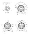
図5及び図6に示すように、特許文献1に記載されたサクションロール110は、両端部に中空状の固定軸131、132を備える円筒状の内筒120と、両固定軸131、132の外側に軸受141、142を介して回転可能に設けられる外筒150と、内筒120の内側に回転可能に設けられる調整軸170とを備えている。As shown in FIGS. 5 and 6, the
外筒150は、ガスが流通するガス吸引部155を円筒壁の全周に亘って備えている。外筒150の両端部にはサイドフランジ151、152が設けられ、両端部を閉塞すると共に軸受141、142が取り付けられている。また、サイドフランジ152は駆動軸154を備えている。The
内筒120は、その外表面を外筒150の内表面に近接させて形成されると共に、軸線方向に沿ってガイド孔123を備えている。これにより、円筒壁の内外を連通して空気の流通が可能な吸引領域161を形成している。ガイド孔123は、断面がほぼ一様な形状に形成され、軸芯とガイド孔123とを結んでできる角度が吸引角θとなる。 The
調整軸170は、中央部を除く両端部側に雄ネジが形成されたネジ部171、172を備えると共に、夫々のネジ部171、172はこれに螺合する雌ネジが形成されたシール部材181、182を備えている。シール部材181、182は、その外周面が内筒120の内表面に近接すると共に、ガイド孔123に対応する部分は拡径して外筒150の内表面に近接するように形成されている。 The
ネジ部171及び172は、互いに逆ネジに形成されている。したがって、調整軸170を外部から回転することにより、シール部材181及び182が、相互に近接又は離間することになるので、吸引領域161の吸引幅wを変更することができる。 The
また、調整軸170は、その中央部に筒状の吸引管175を備えている。この吸引管175の円筒壁には内外を連通する開口176を形成すると共に、ネジ部171を中空として吸引管175と中空状の固定軸131とを連通するガス吸引路177を形成している。Further, the adjusting
このサクションロール110を使用するときは、両固定軸131、132を固定枠等に取り付け、別途設けた駆動源により駆動軸154を回転する。同時に、固定軸131を真空ポンプ等の減圧源に接続し、吸引管175を通じて吸引領域161の両シール部材181、182間を減圧状態とする。これにより、搬送物を外筒150に巻き付かせて、吸着搬送することができる。When this
そして、搬送物の変更等により吸引幅wを変更したい場合には、調整軸170を回転することにより、シール部材181、182をスライドさせることによって、調整することができる。If the suction width w is desired to be changed by changing the conveyed product or the like, it can be adjusted by rotating the
しかしながら、このサクションロール110は、吸引幅wは変更できるものの吸引角θを変更することが不可能であり、汎用性の高いサクションロールとすることができない欠点がある。However, the
したがって、本発明の目的は、吸引幅wを自由に変更できると共に、吸引角θも変更可能なサクションロールを提供することにある。そして、搬送物の変更や使用する機械の変更に対して、簡単な調整で対応可能な汎用性の高いサクションロールを提供することにある。Accordingly, an object of the present invention is to provide a suction roll in which the suction width w can be freely changed and the suction angle θ can be changed. And it is providing the highly versatile suction roll which can respond to the change of a conveyed product, or the change of the machine to be used by simple adjustment.
上記の課題を解決するために、本発明の請求項1に係るサクションロールは、両端部に中空状の固定軸を備える円筒状の内筒と、前記両固定軸の外側に軸受を介して回転可能に設けられる外筒と、前記内筒の内側に回転可能に設けられる調整軸とを備えるサクションロールであって、前記外筒は、ガスが流通するガス吸引部を円筒壁の全周に亘って備え、前記内筒は、円筒壁外面に、外筒との間を軸方向にシールする交換可能な複数の吸引角ブロックを備え、該吸引角ブロック間に吸引領域を形成し、前記内筒の円筒壁は、前記吸引領域に内外を連通する複数の吸引孔を備えると共に、その両端部から軸線に沿って内外を連通するガイド孔を備え、前記調整軸は、前記両ガイド孔に対応する位置に雄ネジが形成されたネジ部を備えると共に、両ネジ部はこれに螺合するナットを備え、前記両ナットには、前記吸引領域において、前記内筒と前記外筒の間を周方向にシールする交換可能なシール部材が、前記ガイド孔を通して取り付けられ、前記調整軸を外部から回転して両シール部材間の距離を変更することにより、前記吸引領域の吸引長さを変更可能とした手段を採用している。In order to solve the above-mentioned problem, a suction roll according to claim 1 of the present invention is rotated through a cylindrical inner cylinder having hollow fixed shafts at both ends and bearings on both outer sides of the fixed shafts. A suction roll comprising an outer cylinder that can be provided and an adjustment shaft that is rotatably provided inside the inner cylinder, wherein the outer cylinder has a gas suction portion through which gas flows around the entire circumference of the cylindrical wall. The inner cylinder includes a plurality of exchangeable suction angle blocks that seal the space between the outer cylinder in the axial direction on the outer surface of the cylindrical wall, and forms a suction region between the suction angle blocks, and the inner cylinder The cylindrical wall includes a plurality of suction holes that communicate with the suction area inside and outside, and also includes guide holes that communicate with the inside and outside along the axis from both ends thereof, and the adjustment shaft corresponds to the both guide holes. In addition to having a threaded part with a male thread formed at the position, The threaded portion includes a nut that is screwed to the nut, and an interchangeable seal member that seals between the inner cylinder and the outer cylinder in the circumferential direction in the suction region is attached to the nuts through the guide hole. Further, a means is adopted in which the suction length of the suction region can be changed by rotating the adjustment shaft from the outside to change the distance between the two seal members.
また、本発明の請求項2に係るサクションロールは、請求項1に記載のサクションロールであって、前記調整軸は、その中央部に筒状の吸引管を備え、該吸引管の円筒壁に内外を連通する開口を形成すると共に、前記ネジ部の1つを中空としてガス吸引路を形成した手段を採用している。また、本発明の請求項3に係るサクションロールは、請求項1又は2に記載のサクションロールであって、前記外筒が、一方の側に駆動軸を備えると共に、該駆動軸が減圧ブロックを備え、該減圧ブロックが前記一方の固定軸及び前記ガス吸引路を経由して前記吸引管に連通している手段を採用している。A suction roll according to a second aspect of the present invention is the suction roll according to the first aspect, wherein the adjustment shaft includes a cylindrical suction pipe at a central portion thereof, and is provided on a cylindrical wall of the suction pipe. An opening that communicates the inside and the outside is formed, and a gas suction path is formed by making one of the screw portions hollow. A suction roll according to claim 3 of the present invention is the suction roll according to claim 1 or 2, wherein the outer cylinder includes a drive shaft on one side, and the drive shaft includes a decompression block. The decompression block employs means that communicates with the suction pipe via the one fixed shaft and the gas suction path.
本発明のサクションロールは、内筒の外表面に平行に取り付けられた吸引角ブロックによって吸引角θが決められる。そして、吸引角ブロックは交換可能であり、取付数や取付位置等を変更することにより吸引角θを自由に変更することができる。また、吸引角ブロックの変更に伴って、吸引幅wを調整するシール部材の形状も変更する必要があるが、シール部材も容易に変更することができる。In the suction roll of the present invention, the suction angle θ is determined by the suction angle block attached in parallel to the outer surface of the inner cylinder. The suction angle block can be exchanged, and the suction angle θ can be freely changed by changing the number of attachments, the attachment position, and the like. In addition, the shape of the seal member that adjusts the suction width w needs to be changed along with the change of the suction angle block, but the seal member can also be easily changed.
したがって、本発明のサクションロールは、吸引幅wを自由に変更することができると共に、小さな部品を交換することにより吸引角θを変更することができるサクションロールとすることができる。そして、搬送物の変更や機械の変更に対して、部品交換または部品調整で対応可能であり、汎用性の高いサクションロールとすることができる。Therefore, the suction roll of the present invention can be a suction roll that can freely change the suction width w and can change the suction angle θ by exchanging small parts. And it can respond to the change of a conveyed product, or the change of a machine by parts replacement | exchange or parts adjustment, and it can be set as a highly versatile suction roll.
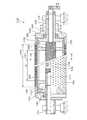
以下、本発明を図に示す実施例により説明するが、これらの図は本発明を何ら限定するものではない。図1は、本発明のサクションロール10の概略断面図であり、図2は、図1における各矢視の概略断面図である。図3は、内筒20の外表面に取り付けられるシール部材81等を示す概略斜視図である。Hereinafter, the present invention will be described with reference to examples shown in the drawings. However, these drawings do not limit the present invention. FIG. 1 is a schematic cross-sectional view of the
本発明のサクションロール10は、前述のサクションロール110と同様に、両端部に中空状の固定軸31、32を備える円筒状の内筒20と、両固定軸31、32の外側に軸受41、42を介して回転可能に設けられる外筒50と、内筒20の内側に回転可能に設けられる調整軸70とを備えている。The
外筒50は、両端部を除き、ガスが流通するガス吸引部55を円筒壁の全周に亘って備えている。ガス吸引部55は、円筒壁に多数の孔56を穿設して形成することができる。搬送物に対する吸引力を一様にするためには、直径が1〜5mm程度の多数の孔56を穿設した外筒50の外周面に、さらに通気構造のニッケルメッシュスリーブ等で被覆することが好ましい。このガス吸引部55の長さが、搬送物に対する吸着幅wの最大値となる。The
外筒50の両端部には、サイドフランジ51、52が設けられ、両端部を閉塞すると共に軸受41、42が取り付けられている。また、サイドフランジ51には駆動軸54が取り付けられ、プーリー43等を取り付けて駆動することができる。
内筒20は、円筒壁外面に、外筒50との間を軸方向にシールする交換可能な2本の吸引角ブロック63、64を備え、両吸引角ブロック63、64間に吸引領域61を形成している。すなわち、吸引角ブロック63、64の対向する2側面は、その内側に吸引領域61を形成し、内筒20の軸線と結んでできる角度が吸引角θとなる。 The
内筒20の円筒壁は、吸引領域61に内外を連通する複数の吸引孔22を備えると共に、その両端部から軸線に沿って内外を連通するガイド孔23、24を備え、後述するシール部材81、82が軸線に沿ってスライドするときに、これをガイドする。 The cylindrical wall of the
調整軸70は、両ガイド孔23、24に対応する位置に雄ネジが形成されたネジ部71、72を備えている。そして、ネジ部71、72に形成される雄ネジは、互いに逆ネジとして形成されている。また、両ネジ部71、72は、これに螺合する雌ネジを備えたナット73、74を備えている。調整軸70の一端は、固定軸32から機外に延長され、機外から手動又は自動で回転することができる。The
両ナット73、74には、内筒20内を摺動するスライドブッシュ75、76が取り付けられ、さらに、スライドブッシュ75、76には、内筒20と外筒50との間を周方向にシールする交換可能なシール部材81、82が、ガイド孔23、24を通して取り付けられている。したがって、両シール部材81、82の間の距離が、吸引領域61の軸方向長さ、すなわち吸引幅wとなる。 Both
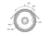
図3に示すように、内筒20の外表面には、軸線に沿って浅い溝が形成され、この溝に吸引角ブロック63、64が嵌め込まれるとともに、ネジで固定されている。また、吸引角ブロック63、64の間には、軸線に沿って3つのガイド孔23、23、23が形成され、これらの間には吸引孔22が形成されている。As shown in FIG. 3, a shallow groove is formed along the axis on the outer surface of the
3つのガイド孔23、23、23には夫々T字型のシール部材81、81、81が差し込まれ、内筒20内のスライドブッシュにネジで固定されている。このように、シール部材81を分割することにより、製作、取り付け及び交換を容易にすることができる。T-shaped
機外から調整軸70を回転すると、シール部材81、82がガイド孔23、24によってガイドされるので、ナット73、74は周方向に回転することはできず、軸方向にスライドすることになる。すなわち、調整軸70を回転することにより、シール部材81、82が、相互に接近又は離間することになるので、これによって吸引幅wが調整されることになる。When the
本発明のサクションロール10は、交換可能な吸引角ブロック63、64及び交換可能なシール部材81を使用して吸引領域61を形成することを特徴としている。すなわち、これによって、吸引幅wを調整することができると共に、簡単に吸引角θを変更することができる。The
例えば、内筒20が、3個以上の吸引角ブロックを取り付け可能な状態に形成し、適当な間隔を選択して2つの吸引角ブロックを取り付けることにより、吸引角θを選択することができる。For example, the suction angle θ can be selected by forming the
吸引角θの変更について、さらに好ましい手段を図4により説明する。
図4は、内筒20に4本の吸引角ブロック63a、63b、64a、64bを取り付けた場合を示している。夫々の吸引角ブロック間には、ガイド孔23a、23b、23cが設けられている。A more preferable means for changing the suction angle θ will be described with reference to FIG.
FIG. 4 shows a case where four
図4(A)は、吸引角ブロック63b、64a間を吸引領域61とした場合を示している。吸引角ブロック63aと63bとの間、及び吸引角ブロック64aと64bとの間には、シールシート65、66を取り付けることにより、吸引孔23a、23cを閉塞している。そして、吸引角ブロック63b、64a間に、シール部材81bを取り付けることにより、狭い吸引角θを形成することができる。FIG. 4A shows a case where the
図4(B)は、吸引角ブロック63a、64b間を吸引領域61とした場合を示している。シールシート65、66を取り外すと共に、ここにシール部材81a、81cが取り付けられている。これによって、吸引角ブロック63a、64b間に、広い吸引角θを形成することができる。FIG. 4B shows a case where the
吸引角θを決める吸引角ブロック63a、63b、64a、64bは、すべり特性に優れた部品を用いており、樹脂系材料を使用しているので、入手及び加工が容易である。そして、内筒20の表面にネジ止めで取り付けられるので、容易に取付及び交換をすることができる。したがって、図4に示すように、吸引角θを容易に変更することができる。The
調整軸70は、その中央部に筒状の吸引管77を備え、吸引管77の円筒壁に内外を連通する開口78を形成している。また、ネジ部71を中空としてガス吸引路79を形成している。The
外筒50は、一方の側に駆動軸54を備えると共に、駆動軸54が減圧ブロック57を備えて、真空ポンプ等の減圧源に接続可能としている。そして、減圧ブロック57が固定軸31及びガス吸引路79を経由して吸引管77に連通している。したがって、減圧ブロックに接続した真空ポンプ等により、吸引管77内を経由して、吸引領域61を減圧することができる。The
なお、本例では、ネジ部71を中空としてガス吸引路79を形成したが、ネジ部72を中空として、固定軸32を経由して減圧することも可能である。In this example, the
以上のように、本発明のサクションロール10は、部品点数が少ないために材料費が安価であり、構造が簡単であるために製作費を低減することができる。As described above, the
10、110 サクションロール
20、120 内筒
22 吸引孔
23、24、123 ガイド孔
31、32、131、132 固定軸
41、42、141、142 軸受
43 プーリー
50、150 外筒
51、52、151、152 サイドフランジ
54、154 駆動軸
55、155 ガス吸引部
56 孔
57 減圧ブロック
61、161 吸引領域
63、64 吸引角ブロック
65、66 シールシート
70、170 調整軸
71、72、171、172 ネジ部
73、74 ナット
75、76 スライドブッシュ
77、175 吸引管
78、176 開口
79、177 ガス吸引路
81、82、181、182 シール部材10, 110 Suction rolls 20, 120
Claims (3)
Translated fromJapanese前記両固定軸の外側に軸受を介して回転可能に設けられる外筒と、
前記内筒の内側に回転可能に設けられる調整軸とを備えるサクションロールであって、
前記外筒は、ガスが流通するガス吸引部を円筒壁の全周に亘って備え、
前記内筒は、円筒壁外面に、外筒との間を軸方向にシールする交換可能な複数の吸引角ブロックを備え、該吸引角ブロック間に吸引領域を形成し、
前記内筒の円筒壁は、前記吸引領域に内外を連通する複数の吸引孔を備えると共に、その両端部から軸線に沿って内外を連通するガイド孔を備え、
前記調整軸は、前記両ガイド孔に対応する位置に雄ネジが形成されたネジ部を備えると共に、両ネジ部はこれに螺合するナットを備え、
前記両ナットには、前記吸引領域において、前記内筒と前記外筒の間を周方向にシールする交換可能なシール部材が、前記ガイド孔を通して取り付けられ、
前記調整軸を外部から回転して両シール部材間の距離を変更することにより、前記吸引領域の吸引長さを変更可能としたことを特徴とするサクションロール。A cylindrical inner cylinder having hollow fixed shafts at both ends;
An outer cylinder rotatably provided via a bearing on the outside of both the fixed shafts;
A suction roll provided with an adjustment shaft rotatably provided inside the inner cylinder,
The outer cylinder is provided with a gas suction portion through which gas flows over the entire circumference of the cylindrical wall,
The inner cylinder includes a plurality of replaceable suction angle blocks that seal the space between the outer cylinder in the axial direction on the outer surface of the cylindrical wall, and forms a suction region between the suction angle blocks;
The cylindrical wall of the inner cylinder includes a plurality of suction holes that communicate with the suction area inside and outside, and includes guide holes that communicate with the inside and outside along the axis from both ends thereof.
The adjustment shaft includes a screw portion in which a male screw is formed at a position corresponding to the both guide holes, and the both screw portions include nuts that are screwed into the screw portion,
An exchangeable seal member that seals between the inner cylinder and the outer cylinder in the circumferential direction in the suction region is attached to the nuts through the guide holes.
A suction roll characterized in that the suction length of the suction region can be changed by rotating the adjustment shaft from the outside to change the distance between both seal members.
Priority Applications (1)
| Application Number | Priority Date | Filing Date | Title |
|---|---|---|---|
| JP2009021213AJP5061133B2 (en) | 2009-02-02 | 2009-02-02 | Suction roll |
Applications Claiming Priority (1)
| Application Number | Priority Date | Filing Date | Title |
|---|---|---|---|
| JP2009021213AJP5061133B2 (en) | 2009-02-02 | 2009-02-02 | Suction roll |
Publications (2)
| Publication Number | Publication Date |
|---|---|
| JP2010173843Atrue JP2010173843A (en) | 2010-08-12 |
| JP5061133B2 JP5061133B2 (en) | 2012-10-31 |
Family
ID=42705184
Family Applications (1)
| Application Number | Title | Priority Date | Filing Date |
|---|---|---|---|
| JP2009021213AActiveJP5061133B2 (en) | 2009-02-02 | 2009-02-02 | Suction roll |
Country Status (1)
| Country | Link |
|---|---|
| JP (1) | JP5061133B2 (en) |
Cited By (7)
| Publication number | Priority date | Publication date | Assignee | Title |
|---|---|---|---|---|
| KR101073850B1 (en) | 2011-07-01 | 2011-10-17 | 주식회사제이에스텍 | Inner cylinder fixing Outer cylinder rotating fabric feeding roll |
| CN103079812A (en)* | 2011-02-21 | 2013-05-01 | 爱诺华李赛克技术中心有限公司 | Method and apparatus for handling sheet blanks |
| KR20140112895A (en)* | 2013-03-14 | 2014-09-24 | 삼성에스디아이 주식회사 | Roller Apparatus |
| CN111890466A (en)* | 2020-08-24 | 2020-11-06 | 深圳市哈德胜精密科技股份有限公司 | A vacuum adsorption device and die-cutting machine |
| KR102484659B1 (en)* | 2021-09-15 | 2023-01-04 | 주식회사제이에스텍 | Apparatus for conneting films without bubble |
| CN115592989A (en)* | 2022-10-18 | 2023-01-13 | 佛山市高明顺恒利塑胶有限公司(Cn) | Manufacturing method of environment-friendly PVC double-sided artificial leather |
| CN119499465A (en)* | 2024-07-31 | 2025-02-25 | 中国人民解放军总医院第一医学中心 | A spinal cord surgery suction device for preventing spinal cord nerve injury |
Citations (2)
| Publication number | Priority date | Publication date | Assignee | Title |
|---|---|---|---|---|
| JPH07127631A (en)* | 1993-11-05 | 1995-05-16 | Berumateitsuku:Kk | Variable suction width type suction roller |
| JP2003072997A (en)* | 2001-08-31 | 2003-03-12 | Fuji Photo Film Co Ltd | Suction roller |
- 2009
- 2009-02-02JPJP2009021213Apatent/JP5061133B2/enactiveActive
Patent Citations (2)
| Publication number | Priority date | Publication date | Assignee | Title |
|---|---|---|---|---|
| JPH07127631A (en)* | 1993-11-05 | 1995-05-16 | Berumateitsuku:Kk | Variable suction width type suction roller |
| JP2003072997A (en)* | 2001-08-31 | 2003-03-12 | Fuji Photo Film Co Ltd | Suction roller |
Cited By (10)
| Publication number | Priority date | Publication date | Assignee | Title |
|---|---|---|---|---|
| CN103079812A (en)* | 2011-02-21 | 2013-05-01 | 爱诺华李赛克技术中心有限公司 | Method and apparatus for handling sheet blanks |
| US9242828B2 (en) | 2011-02-21 | 2016-01-26 | Lisec Austria Gmbh | Method and apparatus for handling sheet blanks |
| KR101073850B1 (en) | 2011-07-01 | 2011-10-17 | 주식회사제이에스텍 | Inner cylinder fixing Outer cylinder rotating fabric feeding roll |
| KR20140112895A (en)* | 2013-03-14 | 2014-09-24 | 삼성에스디아이 주식회사 | Roller Apparatus |
| KR102007413B1 (en)* | 2013-03-14 | 2019-08-05 | 삼성에스디아이 주식회사 | Roller Apparatus |
| CN111890466A (en)* | 2020-08-24 | 2020-11-06 | 深圳市哈德胜精密科技股份有限公司 | A vacuum adsorption device and die-cutting machine |
| KR102484659B1 (en)* | 2021-09-15 | 2023-01-04 | 주식회사제이에스텍 | Apparatus for conneting films without bubble |
| CN115592989A (en)* | 2022-10-18 | 2023-01-13 | 佛山市高明顺恒利塑胶有限公司(Cn) | Manufacturing method of environment-friendly PVC double-sided artificial leather |
| CN115592989B (en)* | 2022-10-18 | 2023-08-11 | 佛山市高明顺恒利塑胶有限公司 | Manufacturing method of environment-friendly PVC double-sided artificial leather |
| CN119499465A (en)* | 2024-07-31 | 2025-02-25 | 中国人民解放军总医院第一医学中心 | A spinal cord surgery suction device for preventing spinal cord nerve injury |
Also Published As
| Publication number | Publication date |
|---|---|
| JP5061133B2 (en) | 2012-10-31 |
Similar Documents
| Publication | Publication Date | Title |
|---|---|---|
| JP5061133B2 (en) | Suction roll | |
| JP4610546B2 (en) | Sheet / film forming roll, sheet / film casting apparatus and fine pattern transfer apparatus | |
| EP2514698B1 (en) | Tube in a rotating folding roll | |
| CN104670949B (en) | A dual-drive precision expansion shaft for flexible film winding process | |
| CN102085746A (en) | Traction roll | |
| JP5193683B2 (en) | Touch roll, main roll, sheet / film casting device and fine pattern transfer device | |
| JP4326515B2 (en) | Sheet / film forming roll and sheet / film forming apparatus | |
| CN111745934A (en) | A mold for producing thick-walled pipes with uniform wall thickness | |
| CN107651475B (en) | Adsorption roller and equipment for processing lamellar products | |
| JP2010173230A (en) | Metal elastic roller | |
| JP2007504957A (en) | Variable crown roller for continuous web material processing apparatus and apparatus comprising said roller | |
| CN207658795U (en) | A kind of adsorption roller and the equipment that thin sheet products are processed | |
| JP2010173842A (en) | Suction roll | |
| CN109353898A (en) | Fast disassembly type spline air-expanding shaft | |
| JP5252295B2 (en) | Winding device | |
| JP2017089676A (en) | Crown adjustment roll | |
| CN204490109U (en) | The accurate swelling shaft of a kind of Dual Drive | |
| CN113103542B (en) | A mold for adjusting diagonal deviation of PVC pipe and adjustment method thereof | |
| JP2024093219A (en) | Inflation molding equipment | |
| WO2014147894A1 (en) | Fluid pressure cylinder and manufacturing method therefor | |
| TWI695777B (en) | Film forming device | |
| US579938A (en) | Rubber-tubing machine | |
| CN101102875B (en) | Device for calendering continuously manufactured articles with at least one calender roller | |
| JP2009000860A (en) | Manufacturing apparatus of sheet member | |
| JP7599988B2 (en) | Inflation molding equipment |
Legal Events
| Date | Code | Title | Description |
|---|---|---|---|
| RD02 | Notification of acceptance of power of attorney | Free format text:JAPANESE INTERMEDIATE CODE: A7422 Effective date:20101118 | |
| A621 | Written request for application examination | Free format text:JAPANESE INTERMEDIATE CODE: A621 Effective date:20110224 | |
| A871 | Explanation of circumstances concerning accelerated examination | Free format text:JAPANESE INTERMEDIATE CODE: A871 Effective date:20120105 | |
| A975 | Report on accelerated examination | Free format text:JAPANESE INTERMEDIATE CODE: A971005 Effective date:20120210 | |
| A977 | Report on retrieval | Free format text:JAPANESE INTERMEDIATE CODE: A971007 Effective date:20120426 | |
| A131 | Notification of reasons for refusal | Free format text:JAPANESE INTERMEDIATE CODE: A131 Effective date:20120508 | |
| A521 | Request for written amendment filed | Free format text:JAPANESE INTERMEDIATE CODE: A523 Effective date:20120622 | |
| TRDD | Decision of grant or rejection written | ||
| A01 | Written decision to grant a patent or to grant a registration (utility model) | Free format text:JAPANESE INTERMEDIATE CODE: A01 Effective date:20120731 | |
| A01 | Written decision to grant a patent or to grant a registration (utility model) | Free format text:JAPANESE INTERMEDIATE CODE: A01 | |
| A61 | First payment of annual fees (during grant procedure) | Free format text:JAPANESE INTERMEDIATE CODE: A61 Effective date:20120806 | |
| FPAY | Renewal fee payment (event date is renewal date of database) | Free format text:PAYMENT UNTIL: 20150810 Year of fee payment:3 | |
| R150 | Certificate of patent or registration of utility model | Ref document number:5061133 Country of ref document:JP Free format text:JAPANESE INTERMEDIATE CODE: R150 Free format text:JAPANESE INTERMEDIATE CODE: R150 | |
| R250 | Receipt of annual fees | Free format text:JAPANESE INTERMEDIATE CODE: R250 | |
| R250 | Receipt of annual fees | Free format text:JAPANESE INTERMEDIATE CODE: R250 | |
| R250 | Receipt of annual fees | Free format text:JAPANESE INTERMEDIATE CODE: R250 |