JP2010167130A - Body fluid collection apparatus and body fluid analyzer - Google Patents
Body fluid collection apparatus and body fluid analyzerDownload PDFInfo
- Publication number
- JP2010167130A JP2010167130AJP2009013126AJP2009013126AJP2010167130AJP 2010167130 AJP2010167130 AJP 2010167130AJP 2009013126 AJP2009013126 AJP 2009013126AJP 2009013126 AJP2009013126 AJP 2009013126AJP 2010167130 AJP2010167130 AJP 2010167130A
- Authority
- JP
- Japan
- Prior art keywords
- body fluid
- bodily fluid
- drug
- bodily
- fluid
- Prior art date
- Legal status (The legal status is an assumption and is not a legal conclusion. Google has not performed a legal analysis and makes no representation as to the accuracy of the status listed.)
- Withdrawn
Links
- 210000001124body fluidAnatomy0.000titleclaimsabstractdescription962
- 239000010839body fluidSubstances0.000titleclaimsabstractdescription684
- 230000001737promoting effectEffects0.000claimsabstractdescription215
- 238000000605extractionMethods0.000claimsabstractdescription167
- 230000007246mechanismEffects0.000claimsabstractdescription138
- 239000002699waste materialSubstances0.000claimsabstractdescription91
- 239000007924injectionSubstances0.000claimsabstractdescription48
- 238000002347injectionMethods0.000claimsabstractdescription48
- 239000003814drugSubstances0.000claimsdescription381
- 229940079593drugDrugs0.000claimsdescription211
- 238000007689inspectionMethods0.000claimsdescription130
- 239000007788liquidSubstances0.000claimsdescription80
- 238000011084recoveryMethods0.000claimsdescription77
- 102000004190EnzymesHuman genes0.000claimsdescription73
- 108090000790EnzymesProteins0.000claimsdescription73
- 229940088598enzymeDrugs0.000claimsdescription73
- 238000012360testing methodMethods0.000claimsdescription49
- 238000000034methodMethods0.000claimsdescription46
- 239000003795chemical substances by applicationSubstances0.000claimsdescription45
- 210000004243sweatAnatomy0.000claimsdescription36
- 239000012530fluidSubstances0.000claimsdescription23
- 239000012482calibration solutionSubstances0.000claimsdescription14
- 238000007599dischargingMethods0.000claimsdescription12
- 230000008569processEffects0.000claimsdescription12
- 230000029142excretionEffects0.000claimsdescription11
- 108010015776Glucose oxidaseProteins0.000claimsdescription10
- 239000004366Glucose oxidaseSubstances0.000claimsdescription10
- 229940116332glucose oxidaseDrugs0.000claimsdescription10
- 235000019420glucose oxidaseNutrition0.000claimsdescription10
- 108010050375Glucose 1-DehydrogenaseProteins0.000claimsdescription9
- KDXKERNSBIXSRK-UHFFFAOYSA-NLysineNatural productsNCCCCC(N)C(O)=OKDXKERNSBIXSRK-UHFFFAOYSA-N0.000claimsdescription9
- 239000004472LysineSubstances0.000claimsdescription9
- 238000007920subcutaneous administrationMethods0.000claimsdescription9
- 238000006243chemical reactionMethods0.000claimsdescription8
- 238000004040coloringMethods0.000claimsdescription7
- 108090000854OxidoreductasesProteins0.000claimsdescription6
- 102000004316OxidoreductasesHuman genes0.000claimsdescription6
- 239000004020conductorSubstances0.000claimsdescription5
- QCHFTSOMWOSFHM-WPRPVWTQSA-N(+)-PilocarpineChemical compoundC1OC(=O)[C@@H](CC)[C@H]1CC1=CN=CN1CQCHFTSOMWOSFHM-WPRPVWTQSA-N0.000claimsdescription4
- QCHFTSOMWOSFHM-UHFFFAOYSA-NSJ000285536Natural productsC1OC(=O)C(CC)C1CC1=CN=CN1CQCHFTSOMWOSFHM-UHFFFAOYSA-N0.000claimsdescription4
- OIPILFWXSMYKGL-UHFFFAOYSA-NacetylcholineChemical compoundCC(=O)OCC[N+](C)(C)COIPILFWXSMYKGL-UHFFFAOYSA-N0.000claimsdescription4
- 229960004373acetylcholineDrugs0.000claimsdescription4
- 229960001416pilocarpineDrugs0.000claimsdescription4
- 239000000284extractSubstances0.000claimsdescription2
- 238000005259measurementMethods0.000abstractdescription27
- 230000037361pathwayEffects0.000abstract2
- 239000000243solutionSubstances0.000abstract1
- 210000003491skinAnatomy0.000description18
- MHAJPDPJQMAIIY-UHFFFAOYSA-NHydrogen peroxideChemical compoundOOMHAJPDPJQMAIIY-UHFFFAOYSA-N0.000description14
- 239000008280bloodSubstances0.000description11
- 210000004369bloodAnatomy0.000description11
- 206010012601diabetes mellitusDiseases0.000description11
- WQZGKKKJIJFFOK-GASJEMHNSA-NGlucoseNatural productsOC[C@H]1OC(O)[C@H](O)[C@@H](O)[C@@H]1OWQZGKKKJIJFFOK-GASJEMHNSA-N0.000description10
- 239000008103glucoseSubstances0.000description10
- 201000010099diseaseDiseases0.000description9
- 208000037265diseases, disorders, signs and symptomsDiseases0.000description9
- QVGXLLKOCUKJST-UHFFFAOYSA-Natomic oxygenChemical compound[O]QVGXLLKOCUKJST-UHFFFAOYSA-N0.000description8
- 239000001301oxygenSubstances0.000description8
- 229910052760oxygenInorganic materials0.000description8
- 230000035900sweatingEffects0.000description8
- 238000010586diagramMethods0.000description6
- 239000002504physiological saline solutionSubstances0.000description6
- 238000004458analytical methodMethods0.000description5
- 230000004048modificationEffects0.000description5
- 238000012986modificationMethods0.000description5
- 210000001519tissueAnatomy0.000description5
- 238000006911enzymatic reactionMethods0.000description4
- NOESYZHRGYRDHS-UHFFFAOYSA-NinsulinChemical compoundN1C(=O)C(NC(=O)C(CCC(N)=O)NC(=O)C(CCC(O)=O)NC(=O)C(C(C)C)NC(=O)C(NC(=O)CN)C(C)CC)CSSCC(C(NC(CO)C(=O)NC(CC(C)C)C(=O)NC(CC=2C=CC(O)=CC=2)C(=O)NC(CCC(N)=O)C(=O)NC(CC(C)C)C(=O)NC(CCC(O)=O)C(=O)NC(CC(N)=O)C(=O)NC(CC=2C=CC(O)=CC=2)C(=O)NC(CSSCC(NC(=O)C(C(C)C)NC(=O)C(CC(C)C)NC(=O)C(CC=2C=CC(O)=CC=2)NC(=O)C(CC(C)C)NC(=O)C(C)NC(=O)C(CCC(O)=O)NC(=O)C(C(C)C)NC(=O)C(CC(C)C)NC(=O)C(CC=2NC=NC=2)NC(=O)C(CO)NC(=O)CNC2=O)C(=O)NCC(=O)NC(CCC(O)=O)C(=O)NC(CCCNC(N)=N)C(=O)NCC(=O)NC(CC=3C=CC=CC=3)C(=O)NC(CC=3C=CC=CC=3)C(=O)NC(CC=3C=CC(O)=CC=3)C(=O)NC(C(C)O)C(=O)N3C(CCC3)C(=O)NC(CCCCN)C(=O)NC(C)C(O)=O)C(=O)NC(CC(N)=O)C(O)=O)=O)NC(=O)C(C(C)CC)NC(=O)C(CO)NC(=O)C(C(C)O)NC(=O)C1CSSCC2NC(=O)C(CC(C)C)NC(=O)C(NC(=O)C(CCC(N)=O)NC(=O)C(CC(N)=O)NC(=O)C(NC(=O)C(N)CC=1C=CC=CC=1)C(C)C)CC1=CN=CN1NOESYZHRGYRDHS-UHFFFAOYSA-N0.000description4
- 239000012528membraneSubstances0.000description4
- 230000035515penetrationEffects0.000description4
- 239000000126substanceSubstances0.000description4
- 230000007423decreaseEffects0.000description3
- 102000004877InsulinHuman genes0.000description2
- 108090001061InsulinProteins0.000description2
- 239000003054catalystSubstances0.000description2
- 239000000470constituentSubstances0.000description2
- 239000011810insulating materialSubstances0.000description2
- 229940125396insulinDrugs0.000description2
- 235000012054mealsNutrition0.000description2
- 230000003340mental effectEffects0.000description2
- 229910052751metalInorganic materials0.000description2
- 239000002184metalSubstances0.000description2
- 238000012544monitoring processMethods0.000description2
- 230000003287optical effectEffects0.000description2
- 230000035699permeabilityEffects0.000description2
- BASFCYQUMIYNBI-UHFFFAOYSA-NplatinumChemical compound[Pt]BASFCYQUMIYNBI-UHFFFAOYSA-N0.000description2
- 238000006479redox reactionMethods0.000description2
- 238000000926separation methodMethods0.000description2
- 238000001228spectrumMethods0.000description2
- 201000004569BlindnessDiseases0.000description1
- LFQSCWFLJHTTHZ-UHFFFAOYSA-NEthanolChemical compoundCCOLFQSCWFLJHTTHZ-UHFFFAOYSA-N0.000description1
- 208000031226HyperlipidaemiaDiseases0.000description1
- 206010020772HypertensionDiseases0.000description1
- 206010028980NeoplasmDiseases0.000description1
- 208000008589ObesityDiseases0.000description1
- 208000001132OsteoporosisDiseases0.000description1
- 102000003992PeroxidasesHuman genes0.000description1
- BQCADISMDOOEFD-UHFFFAOYSA-NSilverChemical compound[Ag]BQCADISMDOOEFD-UHFFFAOYSA-N0.000description1
- 206010040880Skin irritationDiseases0.000description1
- 208000006011StrokeDiseases0.000description1
- 238000010521absorption reactionMethods0.000description1
- 230000009471actionEffects0.000description1
- 238000002266amputationMethods0.000description1
- 238000004364calculation methodMethods0.000description1
- 201000011510cancerDiseases0.000description1
- 239000002775capsuleSubstances0.000description1
- 239000003153chemical reaction reagentSubstances0.000description1
- 238000004891communicationMethods0.000description1
- 238000012937correctionMethods0.000description1
- 238000006356dehydrogenation reactionMethods0.000description1
- 238000001514detection methodMethods0.000description1
- 238000009792diffusion processMethods0.000description1
- 238000010790dilutionMethods0.000description1
- 239000012895dilutionSubstances0.000description1
- 230000035622drinkingEffects0.000description1
- 235000006694eating habitsNutrition0.000description1
- 238000001704evaporationMethods0.000description1
- 239000011521glassSubstances0.000description1
- 230000002641glycemic effectEffects0.000description1
- 210000000987immune systemAnatomy0.000description1
- 230000006872improvementEffects0.000description1
- 239000012535impuritySubstances0.000description1
- 208000015181infectious diseaseDiseases0.000description1
- 238000010030laminatingMethods0.000description1
- 239000004973liquid crystal related substanceSubstances0.000description1
- 208000019423liver diseaseDiseases0.000description1
- 210000003141lower extremityAnatomy0.000description1
- 230000028161membrane depolarizationEffects0.000description1
- 235000020824obesityNutrition0.000description1
- 210000000056organAnatomy0.000description1
- 210000000496pancreasAnatomy0.000description1
- 206010033675panniculitisDiseases0.000description1
- 239000012466permeateSubstances0.000description1
- 108040007629peroxidase activity proteinsProteins0.000description1
- 238000000053physical methodMethods0.000description1
- 229910052697platinumInorganic materials0.000description1
- 230000001681protective effectEffects0.000description1
- 230000027756respiratory electron transport chainEffects0.000description1
- 230000000717retained effectEffects0.000description1
- 230000035945sensitivityEffects0.000description1
- 238000004904shorteningMethods0.000description1
- 229910052709silverInorganic materials0.000description1
- 239000004332silverSubstances0.000description1
- 230000036556skin irritationEffects0.000description1
- 231100000475skin irritationToxicity0.000description1
- 230000000391smoking effectEffects0.000description1
- 210000000434stratum corneumAnatomy0.000description1
- 210000004304subcutaneous tissueAnatomy0.000description1
- 239000000758substrateSubstances0.000description1
- 210000000106sweat glandAnatomy0.000description1
- 208000024891symptomDiseases0.000description1
- 238000012546transferMethods0.000description1
- 239000012780transparent materialSubstances0.000description1
- 210000000707wristAnatomy0.000description1
Images


Classifications
- A—HUMAN NECESSITIES
- A61—MEDICAL OR VETERINARY SCIENCE; HYGIENE
- A61B—DIAGNOSIS; SURGERY; IDENTIFICATION
- A61B5/00—Measuring for diagnostic purposes; Identification of persons
- A61B5/145—Measuring characteristics of blood in vivo, e.g. gas concentration or pH-value ; Measuring characteristics of body fluids or tissues, e.g. interstitial fluid or cerebral tissue
- A61B5/1495—Calibrating or testing of in-vivo probes
- A—HUMAN NECESSITIES
- A61—MEDICAL OR VETERINARY SCIENCE; HYGIENE
- A61B—DIAGNOSIS; SURGERY; IDENTIFICATION
- A61B5/00—Measuring for diagnostic purposes; Identification of persons
- A61B5/145—Measuring characteristics of blood in vivo, e.g. gas concentration or pH-value ; Measuring characteristics of body fluids or tissues, e.g. interstitial fluid or cerebral tissue
- A61B5/14507—Measuring characteristics of blood in vivo, e.g. gas concentration or pH-value ; Measuring characteristics of body fluids or tissues, e.g. interstitial fluid or cerebral tissue specially adapted for measuring characteristics of body fluids other than blood
- A61B5/14517—Measuring characteristics of blood in vivo, e.g. gas concentration or pH-value ; Measuring characteristics of body fluids or tissues, e.g. interstitial fluid or cerebral tissue specially adapted for measuring characteristics of body fluids other than blood for sweat
- A61B5/14521—Measuring characteristics of blood in vivo, e.g. gas concentration or pH-value ; Measuring characteristics of body fluids or tissues, e.g. interstitial fluid or cerebral tissue specially adapted for measuring characteristics of body fluids other than blood for sweat using means for promoting sweat production, e.g. heating the skin
- A—HUMAN NECESSITIES
- A61—MEDICAL OR VETERINARY SCIENCE; HYGIENE
- A61B—DIAGNOSIS; SURGERY; IDENTIFICATION
- A61B5/00—Measuring for diagnostic purposes; Identification of persons
- A61B5/145—Measuring characteristics of blood in vivo, e.g. gas concentration or pH-value ; Measuring characteristics of body fluids or tissues, e.g. interstitial fluid or cerebral tissue
- A61B5/14532—Measuring characteristics of blood in vivo, e.g. gas concentration or pH-value ; Measuring characteristics of body fluids or tissues, e.g. interstitial fluid or cerebral tissue for measuring glucose, e.g. by tissue impedance measurement
- A—HUMAN NECESSITIES
- A61—MEDICAL OR VETERINARY SCIENCE; HYGIENE
- A61B—DIAGNOSIS; SURGERY; IDENTIFICATION
- A61B5/00—Measuring for diagnostic purposes; Identification of persons
- A61B5/145—Measuring characteristics of blood in vivo, e.g. gas concentration or pH-value ; Measuring characteristics of body fluids or tissues, e.g. interstitial fluid or cerebral tissue
- A61B5/1468—Measuring characteristics of blood in vivo, e.g. gas concentration or pH-value ; Measuring characteristics of body fluids or tissues, e.g. interstitial fluid or cerebral tissue using chemical or electrochemical methods, e.g. by polarographic means
- A61B5/1486—Measuring characteristics of blood in vivo, e.g. gas concentration or pH-value ; Measuring characteristics of body fluids or tissues, e.g. interstitial fluid or cerebral tissue using chemical or electrochemical methods, e.g. by polarographic means using enzyme electrodes, e.g. with immobilised oxidase
- A—HUMAN NECESSITIES
- A61—MEDICAL OR VETERINARY SCIENCE; HYGIENE
- A61B—DIAGNOSIS; SURGERY; IDENTIFICATION
- A61B5/00—Measuring for diagnostic purposes; Identification of persons
- A61B5/42—Detecting, measuring or recording for evaluating the gastrointestinal, the endocrine or the exocrine systems
- A61B5/4261—Evaluating exocrine secretion production
- A61B5/4266—Evaluating exocrine secretion production sweat secretion
- A—HUMAN NECESSITIES
- A61—MEDICAL OR VETERINARY SCIENCE; HYGIENE
- A61B—DIAGNOSIS; SURGERY; IDENTIFICATION
- A61B5/00—Measuring for diagnostic purposes; Identification of persons
- A61B5/42—Detecting, measuring or recording for evaluating the gastrointestinal, the endocrine or the exocrine systems
- A61B5/4261—Evaluating exocrine secretion production
- A61B5/4283—Evaluating exocrine secretion production gastrointestinal secretions, e.g. bile production
Landscapes
- Health & Medical Sciences (AREA)
- Life Sciences & Earth Sciences (AREA)
- Physics & Mathematics (AREA)
- Surgery (AREA)
- General Health & Medical Sciences (AREA)
- Biophysics (AREA)
- Pathology (AREA)
- Engineering & Computer Science (AREA)
- Biomedical Technology (AREA)
- Heart & Thoracic Surgery (AREA)
- Medical Informatics (AREA)
- Molecular Biology (AREA)
- Veterinary Medicine (AREA)
- Animal Behavior & Ethology (AREA)
- Public Health (AREA)
- Optics & Photonics (AREA)
- Gastroenterology & Hepatology (AREA)
- Endocrinology (AREA)
- Physiology (AREA)
- Dermatology (AREA)
- Emergency Medicine (AREA)
- Chemical & Material Sciences (AREA)
- Chemical Kinetics & Catalysis (AREA)
- General Chemical & Material Sciences (AREA)
- Measuring And Recording Apparatus For Diagnosis (AREA)
- Measurement Of The Respiration, Hearing Ability, Form, And Blood Characteristics Of Living Organisms (AREA)
- Investigating Or Analysing Biological Materials (AREA)
Abstract
Description
Translated fromJapanese本発明は体液収集装置及び体液分析装置に関する。具体的には、体液抽出を促進させ、体液(汗や細胞液、生体組織の組織液など)を収集または採取するための体液収集装置や体液収集方法に関する。また、収集した体液内の成分の種類や濃度を特定する体液分析装置に関する。 The present invention relates to a body fluid collection device and a body fluid analysis device. Specifically, the present invention relates to a body fluid collection apparatus and body fluid collection method for promoting body fluid extraction and collecting or collecting body fluid (sweat, cell fluid, tissue fluid of biological tissue, etc.). The present invention also relates to a body fluid analyzer that identifies the types and concentrations of components in the collected body fluid.
近年の人間の食生活の変化、運動不足、過労やストレスによる肉体的・精神的な負担、喫煙、飲酒などによって、人間が本来備えている免疫機構に障害が生じて、様々な病気が発症している。これに関する病気の発症や進行には生活習慣が深く関わっているため、一般的に生活習慣病と言われている。生活習慣病には、肥満、高脂血症、糖尿病、高血圧をはじめ、がん、脳卒中、肝臓病、骨粗しょう症なども含まれる。 Recent changes in human eating habits, lack of exercise, physical and mental burdens due to overwork and stress, smoking, alcohol drinking, etc. have caused damage to the immune system inherent in humans, resulting in various diseases. ing. Since lifestyles are deeply involved in the onset and progression of diseases related to this, it is generally called lifestyle-related diseases. Lifestyle-related diseases include obesity, hyperlipidemia, diabetes, hypertension, cancer, stroke, liver disease, and osteoporosis.
特に、糖尿病の患者数は世界的に著しく増加している。日本では、2005年で糖尿病患者数が690万人と言われており、世界では1億7000万人と言われている。糖尿病は自覚症状がないことが多いので、糖尿病といわれても治療しないでいる人が少なくない。治療しないでいると、体の中でじわりと病が進行し、失明や下肢の切断にも至りかねない多くの合併症を招く。このため、病気がどの程度進んでいるのかを定期的にチェック(検査)していく必要がある。チェックを続け血糖コントロールの善し悪しを確認し、合併症の兆候を早めに見つけなければならない。 In particular, the number of diabetic patients is increasing significantly worldwide. In Japan, the number of diabetic patients is said to be 6.9 million in 2005, and is said to be 170 million worldwide. Diabetes often has no subjective symptoms, so there are many people who are not treated even if they say diabetes. If left untreated, the disease progresses gradually in the body, causing many complications that can lead to blindness and amputation of the lower extremities. For this reason, it is necessary to regularly check (inspect) how far the disease has progressed. You should continue to check to see if your glycemic control is good or bad and find signs of complications early.
また糖尿病は、膵臓で分泌されるインスリンの量が不足して、糖分が利用されず、血液中にあふれ出ることで生じる病気である。そのため、血糖を定期的にモニタリングし、その結果をふまえて適量のインスリンを体内に注入する必要がある。 Diabetes mellitus is a disease that occurs when the amount of insulin secreted by the pancreas is insufficient, sugar is not used, and overflows into the blood. Therefore, it is necessary to regularly monitor blood sugar and inject an appropriate amount of insulin into the body based on the result.
現在、血糖をモニタリングするには、実際に採血をし、その酵素反応を電気化学的に、もしくは呈色で検出する。しかし、採血には、数々の懸念事項がある。一つは、皮膚を侵襲して採血することによる肉体的・精神的な負担である。糖尿病患者は食前、食後など1日に数回測定することが求められる。すなわち1日に数回皮膚に針を刺して採血する必要がある。また、血は感染症の恐れがある。また、重度患者では、睡眠中にもモニタリングする必要があり、連続モニタリングが強く望まれている。そのため、皮膚に針を刺さないで(すなわち、非侵襲で)血糖値をモニタリングできるセンサが強く望まれている。 Currently, in order to monitor blood sugar, blood is actually collected and the enzyme reaction is detected electrochemically or by color. However, there are a number of concerns with blood collection. One is a physical and mental burden caused by blood invading the skin. Diabetic patients are required to measure several times a day before meals and after meals. That is, it is necessary to collect blood by inserting a needle into the skin several times a day. Blood can also cause infections. In severe patients, monitoring is also required during sleep, and continuous monitoring is strongly desired. Therefore, a sensor that can monitor blood glucose level without piercing the skin (that is, non-invasively) is strongly desired.
(特許文献1の発明)
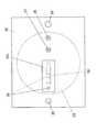
血糖値を測定するための分析センサとしては、特許文献1に開示されたものがある。この分析センサは、図1(a)に示すように、保持部材11の内面に設けられた凹部内にバイオセンサチップ12を取り付けたものである。バイオセンサチップ12は、図1(b)に示すように、基板13の下面に一対の櫛歯状電極14a、14bを形成し、その表面を保護電極15で覆ったものであって、その下面には酵素膜16と分離膜17が積層されている。(Invention of Patent Document 1)
An analysis sensor for measuring a blood glucose level is disclosed in Patent Document 1. As shown in FIG. 1A, this analysis sensor has a
この分析センサは、バイオセンサチップ12の設けられている側の面を皮膚18の表面に圧接させて使用される。皮膚18に圧接された分析センサは、皮膚表面から分泌された汗19を分離膜17を介して採取し、酵素膜16中の酵素と汗19に含まれる成分とを反応させ、その際に生じる電気信号を櫛歯状電極14a、14bで検出する。そして、その検出信号に基づいて汗の成分の種類や量を特定する。こうして非侵襲で汗中のグルコース量を測定することで、分析センサにより血糖値を算出することができる。 This analytical sensor is used with the surface on which the
しかし、この分析センサでは、自然発汗により皮膚から汗を分泌させているので、皮膚からの発汗量が少なく、検査に必要な量の汗を収集するのに長い時間を要していた。 However, in this analytical sensor, since sweat is secreted from the skin by natural sweat, the amount of sweat from the skin is small, and it takes a long time to collect the amount of sweat necessary for the test.
(非特許文献1、特許文献2、3の発明)
このため、薬剤(体液排出促進薬剤)を用いて発汗を促進するイオントフォレシス法が提案されている。非特許文献1に開示されている汗収集システムはイオントフォレシス法を用いたものであり、陰極側の投与電極、陽極側の投与電極および汗収集器を備えている。この汗収集システムの全体の構成は非特許文献1に開示され、投与電極は特許文献2に開示され、汗収集器は特許文献3に開示されている。(Inventions of Non-Patent Document 1, Patent Documents 2 and 3)
For this reason, an iontophoresis method that promotes sweating using a drug (body fluid discharge promoting drug) has been proposed. The sweat collection system disclosed in Non-Patent Document 1 uses an iontophoresis method and includes a cathode side administration electrode, an anode side administration electrode, and a sweat collector. The overall configuration of this sweat collection system is disclosed in Non-Patent Document 1, the administration electrode is disclosed in Patent Document 2, and the sweat collector is disclosed in Patent Document 3.
この汗収集システムにより検査を行う場合には、陰極側の投与電極に体液排出促進薬剤を取り付け、陰極側の投与電極と陽極側の投与電極をそれぞれベルトで腕に取り付けた後、両投与電極間に電圧を印加して体液排出促進薬剤に通電し、腕からの発汗を促す。ついで、投与電極を腕から取り外し、体液排出促進薬剤を当てていた箇所に腕時計型をした汗収集器を取り付ける。汗収集器の下面で腕から抽出された汗は、汗収集器に設けられたスパイラル状の収集チューブに吸い上げられる。十分な汗が収集されたら、ディスペンサによって収集チューブ内の汗を吸い取り、その汗を検査装置に注入して検査装置で検査を行う。 When testing with this sweat collection system, attach a bodily fluid discharge promoting agent to the cathode-side administration electrode, attach the cathode-side administration electrode and the anode-side administration electrode to the arm with a belt, and then between the two administration electrodes. A voltage is applied to the fluid to energize the body fluid discharge promoting drug to promote sweating from the arm. Next, the administration electrode is removed from the arm, and a wristwatch-type sweat collector is attached to the place where the body fluid discharge promoting drug has been applied. The sweat extracted from the arm on the lower surface of the sweat collector is sucked up by a spiral collection tube provided in the sweat collector. When sufficient sweat is collected, the sweat in the collection tube is sucked up by the dispenser, and the sweat is injected into the inspection device, and the inspection device performs the inspection.
このような汗収集システムによれば、体液排出促進薬剤を用いることで発汗量を大きくすることができるので、短時間で汗回収を行うことができる。しかし、腕から必要量の汗を抽出させる時間は短くなるものの、投与電極と汗収集器との付け替えや、収集した汗を収集チューブからディスペンサに移し、さらに検査装置に注入する作業などのため、手間がかかるとともに、検査に要する全体としての時間が長くなっていた。 According to such a sweat collection system, since the amount of sweating can be increased by using the body fluid discharge promoting agent, sweat collection can be performed in a short time. However, although the time to extract the necessary amount of sweat from the arm is shortened, for the work of changing the administration electrode and sweat collector, transferring the collected sweat from the collection tube to the dispenser, and injecting it into the inspection device, etc. In addition to the time and effort, the overall time required for the inspection was long.
また、この汗収集システムでは、検査を行う都度投与電極や汗収集器の腕への付け替えが必要となるため、連続して複数回の検査を行うことが不可能であった。 Also, with this sweat collection system, it is necessary to replace the administration electrode and the arm of the sweat collector each time an inspection is performed, and therefore it is impossible to perform a plurality of inspections continuously.
(特許文献4)
また、特許文献4に開示された分析装置では、生理食塩水を皮膚に接触させ、リバースイオントフォレシス法で体液(組織液)を生理食塩水中に収集し、体液中の特定成分(グルコースなど)を測定する。(Patent Document 4)
Further, in the analyzer disclosed in Patent Document 4, physiological saline is brought into contact with the skin, body fluid (tissue fluid) is collected in physiological saline by reverse iontophoresis, and specific components (such as glucose) in the body fluid are collected. taking measurement.
特許文献4の分析装置では、抽出された体液が生理食塩水中に収集されるので、体液と生理食塩水とが混在し、測定精度への影響が大きい。そのため、体液中の特定成分が低濃度である場合には、その測定が困難である。また、測定対象となる特定成分の種類によっては、生理食塩水中の成分がノイズになって測定精度が低下することもある。また、この分析装置では、体液の混じった生理食塩水を廃液する構造を持たないので、体に装着したままで繰り返し測定を行うことができない。 In the analyzer of Patent Document 4, since the extracted body fluid is collected in physiological saline, the body fluid and physiological saline are mixed, and the influence on measurement accuracy is great. Therefore, when the specific component in the body fluid has a low concentration, the measurement is difficult. In addition, depending on the type of the specific component to be measured, the component in the physiological saline may become noise and the measurement accuracy may decrease. In addition, since this analyzer does not have a structure for draining physiological saline mixed with body fluids, repeated measurement cannot be performed while attached to the body.
本発明の目的とするところは、体液排出促進薬剤を用いて効率よく、かつ非侵襲で体液を収集できながら、体液が体液排出促進薬剤に混じりにくく、混じりものの少ない体液を収集することのできる体液収集装置と体液収集方法を提供することにある。また、夾雑物の少ない体液を用いることで、精度よく検査を行うことのできる体液分析装置を提供することにある。さらには、検査に要する時間を短くするとともに、連続して繰り返し検査を行うことのできる体液分析装置を提供することにある。 An object of the present invention is to collect a bodily fluid that can collect a bodily fluid that is less likely to be mixed with the bodily fluid discharge promoting agent while being able to collect the bodily fluid efficiently and non-invasively using the bodily fluid discharge promoting agent. It is in providing a collection apparatus and a bodily fluid collection method. Moreover, it is providing the body fluid analyzer which can test | inspect accurately by using a body fluid with few impurities. A further object of the present invention is to provide a body fluid analyzer capable of shortening the time required for the examination and continuously performing the examination repeatedly.
上記のような課題を解決するために、本発明にかかる体液収集装置は、被験者の皮下又は体内から体液を抽出し収集する体液収集装置であって、皮下または体内から体液を排出させるための体液排出促進薬剤を体液排出部位上で保持する機能、および体液排出促進薬剤が投与された部位から抽出される体液の収集を行う機能を有する体液抽出部と、前記体液抽出部で一端が開口した、体液排出促進薬剤を回収または廃棄するための薬剤回収通路と、皮下または体内へ投与した後に前記体液抽出部に残った体液排出促進薬剤を、前記薬剤回収通路を通じて回収または廃棄するための薬剤回収機構とを備えて構成されている。 In order to solve the above-mentioned problems, a body fluid collecting device according to the present invention is a body fluid collecting device that extracts and collects body fluid from a subject's skin or body, and is a body fluid for draining body fluid from the body or body. A body fluid extraction unit having a function of holding the drainage promotion drug on the body fluid discharge site and a function of collecting the body fluid extracted from the site to which the body fluid discharge promotion drug has been administered, and one end opened at the body fluid extraction unit, A drug recovery passage for collecting or discarding a bodily fluid discharge promoting drug, and a drug recovery mechanism for collecting or discarding the bodily fluid discharge promoting drug remaining in the bodily fluid extraction part after being administered subcutaneously or into the body through the drug recovery path And is configured.
本発明の体液収集装置は、被験者に苦痛を与えることなく非侵襲で体液を収集することができる装置である。しかも、体液排出促進薬剤を用いて体液の排出を促進させることができるので、体液の回収効率を高めることができ、短い時間で必要な量の体液を収集することができる。しかも、この体液収集装置では、体液抽出部内の体液排出促進薬剤を回収または廃棄するための薬剤回収通路及び薬剤回収機構を備えているので、体液抽出部に体液排出促進薬剤を供給した後、体液を収集する前に、体液抽出部に残った体液排出促進薬剤を体液抽出部から排出することができる。そのため、体液に体液排出促進薬剤が混じって体液が薄くなりにくく、体液のみで測定することが可能になり、体液中の特定成分の検査精度が向上する。また、体液排出促進薬剤の成分がノイズになって検査精度を低下させる恐れも小さくなる。特に、体液中の特定成分が低濃度である場合でも、特定成分の測定が可能になる。 The body fluid collection device of the present invention is a device that can collect body fluid non-invasively without causing pain to a subject. Moreover, since the discharge of body fluid can be promoted using the body fluid discharge promoting medicine, the recovery efficiency of the body fluid can be increased, and a necessary amount of body fluid can be collected in a short time. In addition, since this body fluid collection device is provided with a medicine recovery passage and a medicine recovery mechanism for recovering or discarding the body fluid discharge promoting medicine in the body fluid extraction section, after supplying the body fluid discharge promoting medicine to the body fluid extraction section, Before collecting the body fluid, the body fluid discharge promoting drug remaining in the body fluid extraction unit can be discharged from the body fluid extraction unit. For this reason, the bodily fluid discharge promoting agent is mixed with the bodily fluid discharge facilitating agent, so that the bodily fluid is difficult to be thinned, and measurement can be performed using only the bodily fluid. In addition, the possibility that the component of the body fluid discharge promoting medicine becomes noise and lowers the examination accuracy is reduced. In particular, even when the specific component in the body fluid has a low concentration, the specific component can be measured.
本発明にかかる体液収集装置のある実施態様は、前記体液抽出部へ体液排出促進薬剤を注入するための薬剤注入通路をさらに備えたものである。かかる実施態様によれば、あらかじめ体液抽出部に体液排出促進薬剤を塗布しておく必要がなく、体液収集装置を被験者の腕などに装着した後で、薬剤注入通路から体液抽出部へ体液排出促進薬剤を注入することができる。かかる機能によれば、体液収集装置を腕などに装着したままで、繰り返して複数回体液を収集することを可能にできる。
なお、薬剤注入通路には、ポンプなどの薬剤供給機構を用いて自動的に体液排出促進薬剤を注入してもよく、シリンジや注射器などを用いて手作業で体液排出促進薬剤を注入してもよい。An embodiment of the body fluid collecting device according to the present invention further includes a medicine injection passage for injecting the body fluid discharge promoting medicine into the body fluid extraction unit. According to such an embodiment, it is not necessary to apply the body fluid discharge promoting medicine to the body fluid extraction unit in advance, and after the body fluid collecting device is mounted on the subject's arm or the like, the body fluid discharge is promoted from the medicine injection passage to the body fluid extraction unit. Drugs can be injected. According to such a function, it is possible to repeatedly collect bodily fluids a plurality of times with the bodily fluid collecting device attached to the arm or the like.
In addition, the body fluid discharge promoting medicine may be automatically injected into the medicine injection passage using a medicine supply mechanism such as a pump, or the body fluid discharge promoting medicine may be manually injected using a syringe or a syringe. Good.
本発明にかかる体液収集装置のさらなる実施態様は、体液排出促進薬剤を貯蔵する体液排出促進薬剤貯蔵部と、前記体液排出促進薬剤貯蔵部に貯蔵された体液排出促進薬剤を前記薬剤注入通路から前記体液抽出部に供給するための薬剤供給機構とをさらに備えたものである。かかる実施態様によれば、体液排出促進薬剤貯蔵部内の体液排出促進薬剤を薬剤供給機構によって自動的に体液抽出部へ供給し、さらに薬剤回収機構によって自動的に体液排出促進薬剤を体液抽出部から排出できるので、検査を自動化することができるとともに、検査時間を短縮することができる。
なお、体液排出促進薬剤が液体である場合には、薬剤供給機構としてポンプを用いることができる。A further embodiment of the bodily fluid collecting device according to the present invention includes a bodily fluid discharge promoting drug storage unit that stores a bodily fluid discharge promoting drug, and the bodily fluid discharge promoting drug stored in the bodily fluid discharge promoting drug storage unit from the drug injection passage. And a medicine supply mechanism for supplying the body fluid extraction unit. According to this embodiment, the bodily fluid discharge promoting drug in the bodily fluid discharge promoting drug storage unit is automatically supplied to the bodily fluid extraction unit by the drug supply mechanism, and the bodily fluid discharge promoting drug is automatically supplied from the bodily fluid extraction unit by the drug recovery mechanism Since it can be discharged, the inspection can be automated and the inspection time can be shortened.
When the body fluid discharge promoting medicine is liquid, a pump can be used as the medicine supply mechanism.
本発明にかかる体液収集装置のさらなる実施態様は、前記体液排出促進薬剤が液体であり、前記体液排出促進薬剤貯蔵部が、体液排出促進薬剤を封入した破断可能な液体容器であり、前記薬剤供給機構が、前記液体容器を破断するための破断具であることを特徴としている。かかる実施態様によれば、簡単な構造によって一定量の体液排出促進薬剤を供給することができる。 A further embodiment of the bodily fluid collection device according to the present invention is such that the bodily fluid discharge promoting drug is a liquid, and the bodily fluid discharge promoting drug storage unit is a breakable liquid container enclosing the bodily fluid discharge promoting drug, The mechanism is a breaker for breaking the liquid container. According to this embodiment, a certain amount of the bodily fluid discharge promoting medicine can be supplied with a simple structure.
本発明にかかる体液収集装置のさらなる実施態様は、前記薬剤注入通路に通路開閉用のバルブを設けたものである。かかる実施態様によれば、体液抽出部内の体液排出促進薬剤を排出する際や、検査部内の体液を排出する際に、当該バルブを閉じておくことにより、体液排出促進薬剤貯蔵部から体液排出促進薬剤が引き抜かれるのを防ぐことができる。 In a further embodiment of the body fluid collecting device according to the present invention, a valve for opening and closing the passage is provided in the medicine injection passage. According to this embodiment, when discharging the bodily fluid discharge promoting drug in the bodily fluid extraction unit or discharging the bodily fluid in the examination unit, the body fluid discharge promoting drug storage unit is promoted by closing the valve. The drug can be prevented from being pulled out.
本発明にかかる体液収集装置の別な実施態様は、前記体液排出促進薬剤が液体であり、前記薬剤回収機構は、ポンプを用いて前記体液抽出部へ送入される空気により体液排出促進薬剤を押し出す方法、皮下もしくは体内から前記体液抽出部へ排出される体液により体液排出促進薬剤を押し出す方法、または、ポンプを用いて体液排出促進薬剤を吸引する方法のうちから選択されたいずれかの方法により、体液排出促進薬剤を前記体液抽出部から回収または廃棄するものであることを特徴としている。かかる実施態様によれば、さまざまな方法によって体液排出促進薬剤を回収することができる。 In another embodiment of the bodily fluid collecting device according to the present invention, the bodily fluid discharge promoting drug is a liquid, and the drug collecting mechanism is configured to remove the bodily fluid discharge promoting drug by air fed into the bodily fluid extraction unit using a pump. By any method selected from the method of extruding, the method of extruding the bodily fluid discharge promoting drug with the bodily fluid discharged subcutaneously or from the body to the bodily fluid extraction unit, or the method of sucking the bodily fluid discharge promoting drug using a pump The bodily fluid discharge promoting drug is collected or discarded from the bodily fluid extraction unit. According to such an embodiment, the body fluid discharge promoting medicine can be collected by various methods.
本発明にかかる体液収集装置のさらに別な実施態様は、前記体液排出促進薬剤が液体であり、前記薬剤回収機構は、前記体液抽出部へ揮発性液体を送入し、体液排出促進薬剤と置換もしくは混合し、揮発性液体を揮発させることを特徴としている。かかる実施態様によれば、揮発性液体もしくは体液排出促進薬剤と混合した揮発性液体を揮発させることによって体液排出促進薬剤を体液抽出部から除去することができるので、体液排出促進薬剤をより除去しやすくなる。 Still another embodiment of the bodily fluid collection device according to the present invention is such that the bodily fluid discharge promoting drug is a liquid, and the drug collection mechanism sends the volatile liquid to the bodily fluid extraction unit and replaces it with the bodily fluid discharge promoting drug. Or it mixes and volatilizes a volatile liquid, It is characterized by the above-mentioned. According to this embodiment, since the bodily fluid discharge promoting drug can be removed from the bodily fluid extraction unit by volatilizing the volatile liquid or the volatile liquid mixed with the bodily fluid discharge promoting drug, the bodily fluid discharge promoting drug is further removed. It becomes easy.
本発明にかかる体液収集装置のさらに別な実施態様は、前記体液抽出部で一端が開口した、体液を回収するための体液回収通路と、前記体液抽出部に収集された体液を、前記体液回収通路を通じて回収するための体液回収機構をさらに備えたものである。かかる実施態様によれば、体液回収機構によって体液抽出部で収集した体液を自動的に回収し、さらに薬剤回収機構によって自動的に体液排出促進薬剤を体液抽出部から排出できるので、検査を自動化することができるとともに、検査時間を短縮することができる。 Still another embodiment of the bodily fluid collecting device according to the present invention includes a bodily fluid collecting passage for collecting bodily fluid, one end of which is opened at the bodily fluid extracting unit, and the bodily fluid collected in the bodily fluid extracting unit. A body fluid recovery mechanism for recovering through the passage is further provided. According to this embodiment, the bodily fluid collected by the bodily fluid extraction unit is automatically collected by the bodily fluid collection mechanism, and the bodily fluid discharge promoting drug can be automatically discharged from the bodily fluid extraction unit by the drug collection mechanism, so that the test is automated. And the inspection time can be shortened.
本発明にかかる体液収集装置のさらなる実施態様は、体液排出部位に垂直な方向を含む前記体液抽出部のある断面において、前記体液回収通路の開口端が前記体液抽出部の頂部に位置するように、前記体液抽出部の内壁面を傾斜させたものである。かかる実施態様によれば、被験者の体液排出部位に装着したとき、体液排出部位(皮膚)によって体液回収通路が塞がりにくくなる。また、体液抽出部の容積が小さくなるので、体液排出促進薬剤の消費量を少なくできるとともに、測定時間の短縮化にも寄与できる。 A further embodiment of the bodily fluid collection device according to the present invention is such that, in a cross section of the bodily fluid extraction unit including a direction perpendicular to the bodily fluid discharge site, an open end of the bodily fluid collection passage is located at the top of the bodily fluid extraction unit. The inner wall surface of the body fluid extraction unit is inclined. According to this embodiment, the body fluid recovery passage is not easily blocked by the body fluid discharge site (skin) when attached to the body fluid discharge site of the subject. In addition, since the volume of the body fluid extraction unit is reduced, the consumption of the body fluid discharge promoting medicine can be reduced and the measurement time can be shortened.
本発明にかかる体液収集装置のさらなる実施態様は、前記体液回収通路に通路開閉用のバルブを設けたものである。かかる実施態様によれば、体液抽出部内の体液排出促進薬剤を排出する際には、当該バルブを閉じておくことにより、廃棄体液貯蔵部内の廃棄体液が引き抜かれて逆流するのを防ぐことができる。 In a further embodiment of the bodily fluid collection device according to the present invention, a valve for opening and closing the passage is provided in the bodily fluid collection passage. According to such an embodiment, when discharging the bodily fluid discharge promoting medicine in the bodily fluid extraction part, it is possible to prevent the waste bodily fluid in the waste bodily fluid storage part from being drawn out and flowing backward by closing the valve. .
本発明にかかる体液収集装置のさらに別な実施態様は、前記体液抽出部に保持された体液排出促進薬剤と体液排出部位との間に超音波振動を発生させる機構を有することを特徴としている。かかる実施態様によれば、超音波振動を発生させることによって体液排出促進薬剤の体液排出部位への浸透を促進することができるので、単に体液排出促進薬剤を用いる場合よりも体液の抽出速度を高め、短時間のうちに多くの体液を収集することができる。 Yet another embodiment of the bodily fluid collection device according to the present invention is characterized in that it has a mechanism for generating ultrasonic vibration between the bodily fluid discharge promoting drug held in the bodily fluid extraction unit and the bodily fluid discharge site. According to this embodiment, since the penetration of the body fluid discharge promoting agent into the body fluid discharge site can be promoted by generating ultrasonic vibration, the extraction speed of the body fluid is increased more than when using the body fluid discharge promoting agent. Many body fluids can be collected in a short time.
本発明にかかる体液収集装置のさらに別な実施態様は、前記体液抽出部に保持された体液排出促進薬剤と体液排出部位との間に電流を流すための少なくとも2つの投与電極を有するものである。かかる実施態様によれば、体液排出促進薬剤と体液排出部位との間の電流を流して体液排出促進薬剤の浸透を促進させることができるので、単に体液排出促進薬剤を用いる場合よりも体液の抽出速度を高め、短時間のうちに多くの体液を収集することができる。また、皮下又は体内に入りにくい体液排出促進薬剤でも、電圧を掛けることで皮下又は体内に浸透させやすくなる。 Still another embodiment of the bodily fluid collecting apparatus according to the present invention has at least two administration electrodes for flowing an electric current between the bodily fluid discharge promoting drug held in the bodily fluid extraction unit and the bodily fluid discharge site. . According to this embodiment, since the current between the body fluid discharge promoting drug and the body fluid discharge site can be passed to promote the penetration of the body fluid discharge promoting drug, the extraction of the body fluid is performed more than when the body fluid discharge promoting drug is simply used. The speed can be increased and more body fluids can be collected in a short time. In addition, even if a body fluid excretion promoting drug that is difficult to enter the subcutaneous body or body is easily penetrated into the subcutaneous body or body by applying voltage.
本発明にかかる体液収集装置のさらなる実施態様は、前記体液抽出部へ体液排出促進薬剤を注入するための薬剤注入通路のうち少なくとも前記体液抽出部に近い部分を導電性材料によって形成し、当該薬剤注入通路が、前記投与電極のうちのいずれか一つの投与電極を兼ねるようにしたものである。かかる実施態様によれば、薬剤注入通路が投与電極を兼ねるので、体液収集装置の構造を簡略にすることができる。 In a further embodiment of the body fluid collecting device according to the present invention, at least a part close to the body fluid extraction part in the medicine injection passage for injecting the body fluid discharge promoting medicine into the body fluid extraction part is formed of a conductive material, The injection passage serves as any one of the administration electrodes. According to this embodiment, since the medicine injection passage also serves as the administration electrode, the structure of the body fluid collecting device can be simplified.
また、前記投与電極のうちのいずれか一つの投与電極が、体液抽出部に保持された体液排出促進薬剤と接触するようにして、かつ、薬剤注入通路と異なる位置に設けたものであってもよい。 Further, any one of the administration electrodes may be provided so as to be in contact with the bodily fluid discharge promoting drug held in the bodily fluid extraction unit and at a position different from the drug injection passage. Good.
本発明にかかる体液収集装置のさらなる実施態様は、前記体液抽出部の表面に導電膜を設け、当該導電膜によって前記投与電極のうちのいずれか一つの投与電極を形成したものである。かかる実施態様によれば、投与電極と体液排出促進薬剤との接触面積を広くできるので、体液排出促進薬剤中の気泡によって断線状態となり、体液排出促進薬剤に電圧が掛からなくなるのを防ぐことができる。 In a further embodiment of the bodily fluid collection device according to the present invention, a conductive film is provided on the surface of the bodily fluid extraction part, and any one of the administration electrodes is formed by the conductive film. According to such an embodiment, since the contact area between the administration electrode and the body fluid discharge promoting drug can be widened, it is possible to prevent disconnection due to the bubbles in the body fluid discharge promoting drug and the voltage from being applied to the body fluid discharge promoting drug. .
本発明にかかる体液収集装置のさらに別な実施態様は、前記体液排出促進薬剤がピロカルピンまたはアセチルコリンを含有する薬剤であることを特徴としている。かかる実施態様によれば、体液排出部位からの発汗を促進して短い時間で汗を収集することができる。 Yet another embodiment of the bodily fluid collecting device according to the present invention is characterized in that the bodily fluid discharge promoting drug is a drug containing pilocarpine or acetylcholine. According to this embodiment, sweat can be collected in a short time by promoting sweating from the body fluid discharge site.
本発明にかかる体液収集方法は、本発明にかかる体液収集装置を用いて体液を収集する方法であって、前記体液収集装置を体液排出部位に装着した後、前記体液抽出部に保持された体液排出促進薬剤を皮下または体内に投与するプロセスと、前記薬剤回収機構によって前記体液抽出部に残った体液排出促進薬剤を除去するプロセスと、体液排出促進薬剤が投与された部位から抽出される体液を前記体液抽出部で収集するプロセスとを、前記体液収集装置により順次実行することを特徴としている。 The bodily fluid collecting method according to the present invention is a method of collecting bodily fluid using the bodily fluid collecting apparatus according to the present invention, wherein the bodily fluid held in the bodily fluid extracting unit after the bodily fluid collecting apparatus is attached to the bodily fluid discharge site A process of administering an excretion promoting drug subcutaneously or in the body, a process of removing the bodily fluid discharge promoting drug remaining in the body fluid extraction unit by the drug recovery mechanism, and a body fluid extracted from a site where the bodily fluid discharge promoting drug is administered The process of collecting by the body fluid extraction unit is sequentially executed by the body fluid collection device.
本発明の体液収集方法は、被験者に苦痛を与えることなく非侵襲で体液を収集することができるものである。しかも、体液排出促進薬剤を用いて体液の排出を促進させることができるので、体液の回収効率を高めることができ、短い時間で必要な量の体液を収集することができる。しかも、この体液収集方法では、体液抽出部内の体液排出促進薬剤を回収または廃棄するための薬剤回収通路及び薬剤回収機構を備えているので、体液抽出部に体液排出促進薬剤を供給した後、体液を収集する前に、体液抽出部に残った体液排出促進薬剤を体液抽出部から排出することができる。そのため、体液に体液排出促進薬剤が混じって体液が薄くなりにくく、体液のみで測定することが可能になり、体液中の特定成分の検査精度が向上する。また、体液排出促進薬剤の成分がノイズになって検査精度を低下させる恐れも小さくなる。特に、体液中の特定成分が低濃度である場合でも、特定成分の測定が可能になる。 The body fluid collecting method of the present invention can collect body fluid non-invasively without causing pain to the subject. Moreover, since the discharge of body fluid can be promoted using the body fluid discharge promoting medicine, the recovery efficiency of the body fluid can be increased, and a necessary amount of body fluid can be collected in a short time. In addition, since this body fluid collecting method includes a medicine collection passage and a medicine collection mechanism for collecting or discarding the body fluid discharge promoting medicine in the body fluid extraction part, the body fluid discharge promoting medicine is supplied to the body fluid extraction part, Before collecting the body fluid, the body fluid discharge promoting drug remaining in the body fluid extraction unit can be discharged from the body fluid extraction unit. For this reason, the bodily fluid discharge promoting agent is mixed with the bodily fluid discharge facilitating agent, so that the bodily fluid is difficult to be thinned, and measurement can be performed using only the bodily fluid. In addition, the possibility that the component of the body fluid discharge promoting medicine becomes noise and lowers the examination accuracy is reduced. In particular, even when the specific component in the body fluid has a low concentration, the specific component can be measured.
本発明にかかる体液分析装置は、被験者の皮下または体内から収集した体液中の特定成分を検出または測定する体液分析装置であって、本発明にかかる体液収集装置を、被験者の皮下または体内から収集するための体液収集部として備え、前記体液収集部に設けた前記体液抽出部で収集した体液中の特定成分を検出または測定するための検査部をさらに備えたものである。また、この体液分析装置は、体液収集部と検査部を備えているので、体液分析装置を付け替えることなく、同一装置で連続して体液中の特定成分を検査することができる。 A body fluid analyzer according to the present invention is a body fluid analyzer for detecting or measuring a specific component in a body fluid collected from a subject's subcutaneous body or body, and the body fluid collecting device according to the present invention is collected from a subject's skin or body. And a test part for detecting or measuring a specific component in the body fluid collected by the body fluid extraction part provided in the body fluid collection part. Moreover, since this body fluid analyzer is provided with the body fluid collection part and the test | inspection part, it can test | inspect the specific component in a body fluid continuously with the same apparatus, without replacing a body fluid analyzer.
本発明の体液分析装置は、被験者に苦痛を与えることなく非侵襲で体液中の特定成分を検査することができるものである。しかも、体液排出促進薬剤を用いて体液の排出を促進させることができるので、体液の回収効率を高めることができ、短い時間で必要な量の体液を収集することができ、検査に要する時間を短縮できる。しかも、この体液分析装置では、体液抽出部内の体液排出促進薬剤を回収または廃棄するための薬剤回収通路及び薬剤回収機構を備えているので、体液抽出部に体液排出促進薬剤を供給した後、体液を収集する前に、体液抽出部に残った体液排出促進薬剤を体液抽出部から排出することができる。そのため、体液に体液排出促進薬剤が混じって体液が薄くなりにくく、体液のみで測定することが可能になり、体液中の特定成分の検査精度が向上する。また、体液排出促進薬剤の成分がノイズになって検査精度を低下しにくく、体液分析装置の感度を向上させることができる。特に、体液中の特定成分が低濃度である場合でも、特定成分の測定が可能になる。 The body fluid analyzer of the present invention can inspect a specific component in a body fluid non-invasively without causing pain to a subject. Moreover, since the discharge of body fluid can be promoted by using the body fluid discharge promoting agent, the recovery efficiency of the body fluid can be increased, the necessary amount of body fluid can be collected in a short time, and the time required for the examination can be increased. Can be shortened. In addition, since this body fluid analyzer is provided with a medicine recovery passage and a medicine recovery mechanism for recovering or discarding the body fluid discharge promoting medicine in the body fluid extraction section, the body fluid is discharged after the body fluid discharge promoting medicine is supplied to the body fluid extraction section. Before collecting the body fluid, the body fluid discharge promoting drug remaining in the body fluid extraction unit can be discharged from the body fluid extraction unit. For this reason, the bodily fluid discharge promoting agent is mixed with the bodily fluid discharge facilitating agent, so that the bodily fluid is difficult to be thinned, and measurement can be performed using only the bodily fluid. In addition, the component of the body fluid discharge promoting medicine becomes noise and it is difficult for the test accuracy to decrease, and the sensitivity of the body fluid analyzer can be improved. In particular, even when the specific component in the body fluid has a low concentration, the specific component can be measured.
本発明にかかる体液分析装置のある実施態様は、前記検査部が、体液中の特定成分と特異的に反応する酵素と検査電極からなり、体液中の特定成分と酵素の間で起こる反応により生じる電流に基づく信号を、前記検査電極で検出することにより体液中の特定成分を検出または測定することを特徴としている。かかる実施態様によれば、特定成分と酵素との酸化還元反応によって検査電極間に流れる電流が変化するので、この電流値に基づいて特定成分の有無や量(濃度)を測定することができる。 In one embodiment of the body fluid analyzer according to the present invention, the test section includes an enzyme that specifically reacts with a specific component in the body fluid and a test electrode, and is generated by a reaction that occurs between the specific component in the body fluid and the enzyme. A specific component in the body fluid is detected or measured by detecting a signal based on the current with the test electrode. According to this embodiment, since the current flowing between the test electrodes changes due to the oxidation-reduction reaction between the specific component and the enzyme, the presence / absence and amount (concentration) of the specific component can be measured based on this current value.
本発明にかかる体液分析装置の別な実施態様は、前記検査部が、体液中の特定成分と特異的に反応する酵素と発色色素からなり、体液中の特定成分と前記酵素及び前記発色色素との呈色反応を光学的に検出することにより体液中の特定成分を検出または測定することを特徴としている。かかる実施態様によれば、体液中の特定成分と酵素及び発色色素との呈色反応を光学的に検出し、その波長スペクトルなどに基づいて特定成分の有無や量(濃度)を測定することができる。 Another embodiment of the body fluid analyzer according to the present invention is such that the inspection unit comprises an enzyme and a coloring dye that reacts specifically with a specific component in the body fluid, and the specific component in the body fluid, the enzyme, and the coloring dye. It is characterized in that a specific component in a body fluid is detected or measured by optically detecting the color reaction. According to this embodiment, the color reaction between the specific component in the body fluid and the enzyme and the coloring dye is optically detected, and the presence or amount (concentration) of the specific component is measured based on the wavelength spectrum or the like. it can.
本発明にかかる体液分析装置のさらなる実施態様は、前記検査部を2つ以上備え、前記検査部はそれぞれ互いに異なる種類の酵素を有するものである。かかる実施態様によれば、各酵素でそれぞれ異なる特定成分を検査することができ、複数の特定成分を同時に(一回で)測定することが可能になり、効率よく検査を行うことができる。 A further embodiment of the body fluid analyzer according to the present invention is provided with two or more test sections, and each of the test sections has different types of enzymes. According to such an embodiment, different specific components can be inspected for each enzyme, and a plurality of specific components can be measured simultaneously (in one time), thereby enabling efficient inspection.
本発明にかかる体液分析装置のさらなる実施態様は、前記検査部を2つ以上備え、前記検査部はそれぞれ同一種類の酵素を有するものである。かかる実施態様によれば、各酵素で同じ特定成分を検査することができるので、1つの特定成分を一度に複数回測定することが可能になり、測定精度の高精度化を図ることができる。 A further embodiment of the body fluid analyzer according to the present invention is provided with two or more inspection units, and each of the inspection units has the same type of enzyme. According to this embodiment, since the same specific component can be tested with each enzyme, one specific component can be measured a plurality of times at a time, and the measurement accuracy can be increased.
本発明にかかる体液分析装置のさらなる実施態様は、前記検査部を4つ以上備え、互いに異なる種類の酵素を有する検査部の組合せを1セットとし、前記1セットの検査部を複数セット有するものである。かかる実施態様によれば、複数の特定成分を一回で測定することができるとともに、同じ特定成分を複数回測定することが可能になり、測定作業の効率化と測定精度の高精度化を図ることができる。 A further embodiment of the body fluid analyzer according to the present invention comprises four or more test units, a combination of test units having different types of enzymes, and a plurality of sets of the one test unit. is there. According to such an embodiment, it is possible to measure a plurality of specific components at a time and to measure the same specific component a plurality of times, thereby improving the efficiency of measurement work and increasing the accuracy of measurement. be able to.
本発明にかかる体液分析装置のさらに別な実施態様は、前記検査部の校正を行うための校正液を貯蔵する校正液貯蔵部と、前記校正液貯蔵部に貯蔵された校正液を前記検査部に供給するための校正液供給機構とを備えたものである。かかる実施態様によれば、校正液を用いて検査部の測定値を校正することができ、体液分析装置の測定精度を高精度化することができる。また、校正液供給機構によって校正液貯蔵部内の校正液を検査部へ送ることができるので、校正作業を自動化することができる。 Still another embodiment of the body fluid analyzer according to the present invention includes a calibration solution storage unit that stores a calibration solution for calibrating the inspection unit, and a calibration solution stored in the calibration solution storage unit. And a calibration liquid supply mechanism for supplying to the liquid crystal. According to this embodiment, the measurement value of the inspection unit can be calibrated using the calibration liquid, and the measurement accuracy of the body fluid analyzer can be increased. Moreover, since the calibration liquid in the calibration liquid storage unit can be sent to the inspection unit by the calibration liquid supply mechanism, the calibration work can be automated.
本発明にかかる体液分析装置のさらに別な実施態様は、前記体液抽出部で一端が開口した、体液を回収するための体液回収通路と、検査後の体液を廃棄するための廃棄体液貯蔵部と、前記体液抽出部に収集された体液を、前記体液回収通路を通じて回収し、前記検査部による検査後の体液を前記廃棄体液貯蔵部へ廃棄するための体液回収機構とをさらに備えたものである。かかる実施態様によれば、体液回収機構を稼働させることにより、体液抽出部に収集した体液を検査部へ送り、さらに検査部で検査された後の廃棄体液を廃棄体液貯蔵部へ自動的に回収または廃棄することができるので、体液の検査をより自動化することができ、検査所要時間をより短くできる。 Still another embodiment of the bodily fluid analyzer according to the present invention includes a bodily fluid collection passage for collecting bodily fluid, one end of which is opened by the bodily fluid extraction unit, and a waste bodily fluid storage unit for discarding the bodily fluid after the test. And a body fluid recovery mechanism for recovering the body fluid collected in the body fluid extraction unit through the body fluid recovery passage and discarding the body fluid after the inspection by the inspection unit to the waste body fluid storage unit. . According to such an embodiment, by operating the body fluid recovery mechanism, the body fluid collected by the body fluid extraction unit is sent to the inspection unit, and the waste body fluid after being inspected by the inspection unit is automatically recovered to the waste body fluid storage unit Or since it can be discarded, the inspection of the body fluid can be automated, and the time required for the inspection can be shortened.
本発明にかかる体液分析装置のさらに別な実施態様は、グルコースオキシダーゼ又はグルコース脱水素酵素を酵素とする前記検査部を備えたものである。酵素としてグルコースオキシダーゼ又はグルコース脱水素酵素を用いれば、体液中のグルコースの量(濃度)を測定することができ、検査結果を糖尿病検査などに用いることができる。 Still another embodiment of the body fluid analyzer according to the present invention is provided with the above-described test section using glucose oxidase or glucose dehydrogenase as an enzyme. If glucose oxidase or glucose dehydrogenase is used as the enzyme, the amount (concentration) of glucose in the body fluid can be measured, and the test result can be used for a diabetes test or the like.
本発明にかかる体液分析装置のさらに別な実施態様は、グルコースオキシダーゼ又はグルコース脱水素酵素を酵素とする前記検査部と、リジンオキシダーゼを酵素とする前記検査部とを備えたものである。一部の酵素としてリジンオキシダーゼを用い、他の酵素としてグルコースオキシダーゼ又はグルコース脱水素酵素を用いれば、リジンオキシダーゼによってリジンの量を検出することができるので、リジンを補正物質として測定することでグルコースの測定精度を高めることができる。 Still another embodiment of the body fluid analyzer according to the present invention includes the above-described test unit using glucose oxidase or glucose dehydrogenase as an enzyme and the test unit using lysine oxidase as an enzyme. If lysine oxidase is used as part of the enzyme and glucose oxidase or glucose dehydrogenase is used as the other enzyme, the amount of lysine can be detected by lysine oxidase. Measurement accuracy can be increased.
本発明にかかる体液分析装置のさらに別な実施態様は、前記体液排出促進薬剤貯蔵部に貯蔵された体液排出促進薬剤を前記体液抽出部に供給するための薬剤供給機構と、検査後の体液を廃棄するための廃棄体液貯蔵部と、前記体液抽出部に収集された体液を回収し、前記検査部による検査後の体液を前記廃棄体液貯蔵部へ廃棄するための体液回収機構とをさらに備えたものである。かかる実施態様によれば、体液排出促進薬剤を体液抽出部に供給する動作、体液抽出部内の体液排出促進薬剤を排出する動作、体液抽出部に収集した体液を検査部で検査した後に廃棄体液貯蔵部へ廃棄する動作などを自動化することができ、慣れていない被験者であっても被験者自ら体液の検査を容易に行うことができる。また、体液分析装置を腕などにつけたままで、くりかえし検査を行うことが可能になる。 Still another embodiment of the body fluid analyzer according to the present invention includes a drug supply mechanism for supplying the body fluid discharge promoting medicine stored in the body fluid discharge promoting medicine storage section to the body fluid extraction section, and a body fluid after the test. A waste body fluid storage unit for discarding, and a body fluid recovery mechanism for recovering the body fluid collected in the body fluid extraction unit and discarding the body fluid after the inspection by the inspection unit to the waste body fluid storage unit Is. According to such an embodiment, the operation of supplying the body fluid discharge promoting drug to the body fluid extraction unit, the operation of discharging the body fluid discharge promoting agent in the body fluid extraction unit, and the body fluid storage after the body fluid collected in the body fluid extraction unit is inspected by the inspection unit It is possible to automate the operation of discarding the body, etc., and even if the subject is not used to it, the subject himself can easily inspect the body fluid. In addition, repeated examinations can be performed with the body fluid analyzer attached to the arm or the like.
本発明にかかる体液分析装置のさらなる実施態様は、前記体液回収通路が前記薬剤回収通路を兼ね、前記廃棄体液貯蔵部が前記廃棄薬剤貯蔵部を兼ねており、前記薬剤回収機構が前記薬剤供給機構を利用したものである。かかる実施態様によれば、薬剤供給機構とは別に薬剤回収機構を設ける必要がなく、体液回収通路とは別に薬剤回収通路を設ける必要がなく、また廃棄体液貯蔵部とは別に廃棄薬剤貯蔵部を設ける必要がないので、体液分析装置の構造を簡素化でき、コストを安価にすることができる。 In a further embodiment of the body fluid analyzer according to the present invention, the body fluid collection passage also serves as the medicine collection passage, the waste body fluid storage section serves as the waste medicine storage section, and the medicine collection mechanism serves as the medicine supply mechanism. Is used. According to this embodiment, it is not necessary to provide a drug recovery mechanism separately from the drug supply mechanism, it is not necessary to provide a drug recovery path separately from the body fluid recovery path, and the waste drug storage section is provided separately from the waste body fluid storage section. Since it is not necessary to provide it, the structure of the body fluid analyzer can be simplified and the cost can be reduced.
本発明にかかる体液分析装置のさらなる実施態様は、前記体液回収機構が、前記薬剤供給機構を利用したものである。かかる実施態様によれば、薬剤供給機構とは別に体液回収機構を設ける必要がないので、体液分析装置の構造を簡素化でき、コストを安価にすることができる。 In a further embodiment of the body fluid analyzer according to the present invention, the body fluid recovery mechanism uses the drug supply mechanism. According to such an embodiment, since it is not necessary to provide a body fluid recovery mechanism separately from the medicine supply mechanism, the structure of the body fluid analyzer can be simplified and the cost can be reduced.
本発明にかかる体液分析装置のさらなる実施態様は、体液排出部位に装着するための体液収集チップと、据え置きされる分析装置本体とからなり、前記体液収集チップは、前記体液抽出部および前記検査部を備え、前記分析装置本体は、前記薬剤供給機構、前記薬剤回収機構、前記体液回収機構および前記廃棄体液貯蔵部を備えたものである。かかる実施態様によれば、被験者に装着する体液収集チップを小型軽量化できるので、体液分析装置の装着感が良好となる。 A further embodiment of the bodily fluid analyzer according to the present invention comprises a bodily fluid collection chip for mounting on a bodily fluid discharge site, and a stationary analyzer main body, wherein the bodily fluid collection chip includes the bodily fluid extraction unit and the inspection unit. The analyzer main body includes the drug supply mechanism, the drug recovery mechanism, the body fluid recovery mechanism, and the waste body fluid storage unit. According to this embodiment, the body fluid collecting chip to be attached to the subject can be reduced in size and weight, so that the body fluid analyzer can be worn comfortably.
本発明にかかる体液分析装置のさらなる実施態様は、体液排出部位に装着するための分析装置本体と、前記分析装置本体に着脱自在に装着できる体液収集チップとからなり、前記体液収集チップは、前記体液抽出部および前記検査部を備え、前記分析装置本体は、前記薬剤供給機構、前記薬剤回収機構、前記体液回収機構および前記廃棄体液貯蔵部を備えていることを特徴としている。かかる実施態様によれば、分析装置本体を被験者に装着したままで、体液収集チップを分析装置本体から取り出して交換し、連続して検査を行うことができる。 A further embodiment of the body fluid analyzer according to the present invention comprises an analyzer main body for mounting on a body fluid discharge site, and a body fluid collecting chip that can be detachably mounted on the analyzer main body. A body fluid extraction unit and the inspection unit are provided, and the analyzer main body includes the drug supply mechanism, the drug recovery mechanism, the body fluid recovery mechanism, and the waste body fluid storage unit. According to such an embodiment, the body fluid collection chip can be taken out from the analyzer body and replaced while the analyzer body is attached to the subject, and the test can be continuously performed.
本発明にかかる体液分析装置のさらなる実施態様は、体液排出部位に装着するための体液収集チップに、前記体液抽出部、前記薬剤供給機構、前記薬剤回収機構、前記検査部、前記体液回収機構および前記廃棄体液貯蔵部を備えていることを特徴としている。かかる実施態様によれば、体液分析装置が一体化されているので、体液分析装置の構造を簡単にすることができる。 A further embodiment of the bodily fluid analyzer according to the present invention includes a bodily fluid collection chip for mounting on a bodily fluid discharge site, the bodily fluid extraction unit, the drug supply mechanism, the drug recovery mechanism, the inspection unit, the bodily fluid recovery mechanism, and The waste body fluid storage unit is provided. According to this embodiment, since the body fluid analyzer is integrated, the structure of the body fluid analyzer can be simplified.
なお、本発明における前記課題を解決するための手段は、以上説明した構成要素を適宜組み合せた特徴を有するものであり、本発明はかかる構成要素の組合せによる多くのバリエーションを可能とするものである。 The means for solving the above-described problems in the present invention has a feature in which the above-described constituent elements are appropriately combined, and the present invention enables many variations by combining such constituent elements. .
以下、添付図面を参照しながら本発明の好適な実施形態を説明する。 Hereinafter, preferred embodiments of the present invention will be described with reference to the accompanying drawings.
[第1の実施形態]
本発明の基本的な構成を備えた実施形態1の体液分析装置を説明する。
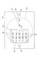
図2は、本発明の実施形態1による体液分析装置21の構成を示す概略断面図である。図3は、この体液分析装置21において体液排出促進薬剤や校正液などを供給及び回収するための構成を示す図である。また、図4は、体液分析装置21に用いられている体液収集チップ22の平面図である。[First Embodiment]
A body fluid analyzer of Embodiment 1 having the basic configuration of the present invention will be described.
FIG. 2 is a schematic cross-sectional view showing the configuration of the
この体液分析装置21は、主として、体液を収集し検査するための体液収集部と、体液収集部に体液排出促進薬剤や校正液などを供給、回収したり、検査後の体液を廃棄したりするための機構部分とからなる。
なお、収集する体液としては、汗がもっとも簡便であり、以下の説明においても汗を収集する場合について説明するが、体液は皮下組織の細胞液、生体組織の組織液などでもよい。The
As the body fluid to be collected, sweat is the simplest, and in the following description, the case of collecting sweat will be described. However, the body fluid may be a cell fluid of subcutaneous tissue, a tissue fluid of biological tissue, or the like.
(体液収集部の説明)
まず、体液収集部を説明する。
図2に示すように、体液収集部は、体液収集チップ22を母体として構成されている。体液収集チップ22は、プラスチックやガラス等の絶縁材料からなる上プレート22aと下プレート22bを積層一体化して構成されている。特に、体液収集チップ22は体液排出部位γに沿って湾曲できるよう、適度な柔軟性を有していることが望ましい。体液収集チップ22の下面には、体液排出促進薬剤を保持し、また体液排出部位γから抽出された体液を収集するための体液抽出部23を備えている。体液抽出部23は、内壁面(上面)が緩やかに傾斜した窪みからなる。例えば、体液抽出部23を円錐状や三角溝状をした窪みで形成している。(Explanation of body fluid collection part)
First, the body fluid collecting unit will be described.
As shown in FIG. 2, the body fluid collection unit is configured with the body
体液抽出部23の内壁面には、金属等の導電膜によって一方の投与電極24を設けている。また、体液収集チップ22の体液抽出部23や投与電極24から離れた位置には、他方の投与電極25を埋め込んであり、投与電極25の下端面は体液収集チップ22の下面に露出している。投与電極24及び25は、イオントフォレシス電源26の出力端子につながれており、イオントフォレシス電源26から投与電極24、25間に電圧を印加できる。 One
イオントフォレシス電源26としては、種々のタイプのものを使用することができる。すなわち、イオントフォレシス電源26としては、直流電流を連続的に流す連続直流型、直流電流を断続的に流すパルス直流型、皮膚刺激の少ないパルス脱分極直流型、交流電流を流す交流型などの電源を用いることができる。 Various types of
体液収集チップ22には、上面から下面に貫通するようにして薬剤注入孔27と薬剤回収孔28を穿孔してあり、薬剤注入孔27と薬剤回収孔28の下端はいずれも体液抽出部23内で開口している。 The body
体液収集チップ22内には、体液抽出部23内に収集された体液を送り出すための体液送出路29が設けられている。体液送出路29は、体液抽出部23の頂部から上方へ向けてあいており、体液送出路29は体液収集チップ22内で水平に延びた後、再び上方へ延びている。 In the body
図2及び図4に示すように、体液送出路29内の、該送出路29が水平に延びている領域には、体液に含まれる特定成分を検査するための検査部30を設けている。検査部30の上面において上プレート22aには開口が設けられており、この開口には検査部カバー22cが着脱可能に嵌め込まれている。前記体液送出路29は検査部30を通過した後、検査部カバー22cを上下に貫通して検査部カバー22cの上面で開口している。 As shown in FIGS. 2 and 4, an
(体液抽出部の説明)
前記体液抽出部23の構造を説明する。
図6(a)は異なる形状の体液抽出部23を示す概略断面図である。この体液収集チップ22では円柱状又は角柱状をした(すなわち、断面が矩形の)体液抽出部23を設けている。体液排出促進薬剤により体液を抽出する際に体液抽出部23内の体液排出促進薬剤が漏れ出ないようにするには、ある程度の圧力で体液収集チップ22を体液排出部位γ(皮膚)に押し付ける必要がある。そのため図6(a)のような形状の体液抽出部23では、体液収集チップ22を体の体液排出部位γに押し付けたとき、図6(b)のように体液排出部位γ(皮膚)が盛り上がって体液抽出部23内に入り込み、体液を回収するための体液送出路29を塞ぐおそれがある。(Description of body fluid extraction unit)
The structure of the body
FIG. 6A is a schematic cross-sectional view showing the body
これに対し、本実施形態の体液収集チップ22では、図5(a)に示すように、体液抽出部23の内壁面は体液送出路29の周囲又は両側で緩やかに傾斜しており、体液送出路29が体液抽出部23の頂部に設けられている。そのため、体液収集チップ22を被験者の体液排出部位γに押し付けて体液排出部位γが体液抽出部23内に入り込んでも、図5(b)に示すように、体液送出路29が塞がれにくく、体液の回収が妨げられにくい。 On the other hand, in the bodily
また、体液抽出部23の内壁面を緩やかに傾斜させていると、体液抽出部23の内部容量を小さくすることができ、体液排出促進薬剤の注入量(消費量)を少なくできる。さらに、体液抽出部23の内部容量を小さくできるので、体液抽出部23内に収集された体液を検査部30へ送り出す際、体液の検査部30への到達速度が大きくなり、計測時間を短くできる。
(検査部の説明)Further, when the inner wall surface of the body
(Explanation of inspection department)
前記検査部30の構造を具体的に説明する。
図7は前記検査部30の具体的な構造の一例を示す概略断面図である。絶縁性材料からなる検査部カバー22cの下面には一対の検査電極54、55が設けられており、検査電極54、55間には電流計56がつながれている。The structure of the
FIG. 7 is a schematic cross-sectional view showing an example of a specific structure of the
検査を行う際には、体液収集チップ22から検査部カバー22cを分離し、一方の検査電極54の表面に検査対象とする特定成分(例えば、グルコース)と特異的に反応する酵素57を固定化し、再び検査部カバー22cを上プレート22aの開口に取り付ける。この結果、検査部30の上面に酵素57が位置することになる。体液抽出部23内で収集された体液βは、体液送出路29内を通って検査部30に送り込まれる。このとき体液βに特定成分εが含まれていると、特定成分εと酵素57との間で酸化還元反応が生じて検査電極54、55間に電流が流れ、この電流は電流計56によって検出される。電子回路によって構成された演算部61(図3参照)では、この電流値に基づいて体液βに特定成分εが含まれているかどうかを判定する。あるいは、体液βに含まれる特定成分εの濃度を算出し、その結果を表示部に表示させる。 When performing the test, the
特定成分εと酵素57との反応量を電気化学的に測定する方法としては、酸素電極を用いる方法、過酸化水素電極を用いる方法、メディエータ型酵素電極を用いる方法などがある。酸素電極を用いる方法では、例えば検査電極54を白金電極、検査電極55を銀電極とする。特定成分εの量が増えると、酵素反応によって酸素の消費量が増えるので、体液中の溶存酸素量が減少する。酸素電極では、この溶存酸素量に比例した電流が流れるので、電流値を計測することによって特定成分εを検出し、あるいはその量を測定することができる。 Methods for electrochemically measuring the reaction amount between the specific component ε and the
過酸化水素電極を用いる場合には、特定成分εの量が増えると、酵素反応によって過酸化水素の発生量が増え、検査電極54、55間の電流値が増加する。従って、特定成分εの量が多いほど電流値が大きくなるので、電流値を計測することによって特定成分εの量を測定することができる。 When the hydrogen peroxide electrode is used, when the amount of the specific component ε increases, the amount of hydrogen peroxide generated increases due to the enzyme reaction, and the current value between the
メディエータ型酵素電極を用いる場合には、特定成分εの酵素反応により発生した電子がメディエータ(電極と酵素の間の電子移動を促進する膜)を介して検査電極54、55で検出される。特定成分εの量が増えるほど伝達される電子が増加し、検査電極54、55間の電流が増加するので、電流値を計測することによって特定成分εの量を測定することができる。 When the mediator type enzyme electrode is used, electrons generated by the enzyme reaction of the specific component ε are detected by the
図8は前記検査部30の具体的な構造の別な例を示す概略断面図である。この検査部30は光学式であって、検査部カバー22cの下面には、特定成分εと特異的に反応する酵素57、発色色素58、過酸化水素に対して触媒となる酵素(ペルオキシダーゼ)を固定化している。また、体液収集チップ22の少なくとも検査部下方の部分を透明材料によって形成し、体液収集チップ22の下方に投光部59と受光部60とを配置している。 FIG. 8 is a schematic cross-sectional view showing another example of the specific structure of the
この検査部30においては、体液βが送り込まれると、特定成分εと酵素57の反応によって過酸化水素が生成する。さらに、過酸化水素に対して触媒となる酵素の働きで、過酸化水素から活性酸素が生成される。この活性酸素と発色色素58の呈色反応により、検査部30における光学的性質(波長または強度)が変化する。従って、投光部59から検査部30に白色光Lを照射し、検査部30で反射した光を受光部60で受光し、反射光の光スペクトルを分析することで体液中の特定成分εを検出し、あるいはその量を測定することができる。 In the
なお、ここでは体液中の特定成分を検出するために酵素を用いたが、これ以外に試薬などを用いてもよい。 Here, an enzyme is used to detect a specific component in a body fluid, but a reagent or the like may be used in addition to this.
図4には1つの検査部30を備えた体液収集チップ22を示しているが、この検査部30を複数設けてアレイ化してもよい。図9は複数の検査部30を備えた体液収集チップ22の一例を示す。図9では体液送出路29の水平に延びた領域を複数本に分岐させ、各体液送出路29に複数の検査部30を設けている。図9では体液送出路29を5本に分岐させ、各体液送出路29にそれぞれ2つの検査部30を設けているが、これらの数に限定されるものではない。なお、図9では検査部カバー22cの上面に複数の体液送出路29が開口しているが、これらの体液送出路29は検査部カバー22cの上方で(あるいは、検査部カバー22cの内部で)1本にまとめられる。 Although FIG. 4 shows the body
アレイ状に配置された複数の検査部30には、それぞれ酵素A1、A2、B1、B2、C1、C2、…が固定化されている。第1の形態としては、これらの酵素A1、A2、B1、B2、C1、C2、…がすべて互いに異なる種類の酵素とすることができる。このような形態によれば、各酵素A1、A2、B1、B2、C1、C2、…でそれぞれ異なる特定成分を検査することができ、複数の特定成分を同時に(一回で)測定することが可能になり、効率よく検査を行うことができる。 Enzymes A1, A2, B1, B2, C1, C2,... Are immobilized on the plurality of
第2の形態としては、これらの酵素A1、A2、B1、B2、C1、C2、…をすべて同じ種類の酵素とすることができる。このような形態によれば、各酵素A1、A2、B1、B2、C1、C2、…で同じ特定成分を検査することができるので、1つの特定成分を一度に複数回測定することが可能になり、測定精度の高精度化を図ることができる。 As the second form, these enzymes A1, A2, B1, B2, C1, C2,... Can all be the same type of enzyme. According to such a form, since the same specific component can be inspected by each enzyme A1, A2, B1, B2, C1, C2,..., One specific component can be measured a plurality of times at a time. Thus, the measurement accuracy can be increased.
第3の形態は、これらの酵素のうち一部は互いに同じ種類の酵素とし、一部は互いに異なる種類の酵素とすることができる。例えば、同じ体液送出路29に属する検査部30を1セットとし、1セット内の検査部30の酵素は互いに異なるものとし、異なるセット間では酵素の組合せを同じにしたものである。図9に即していえば、A1、B1、C1、…は同じ酵素とし、A2、B2、C2、…も同じ酵素とし、酵素A1、B1、C1、…と酵素A2、B2、C2、…とは異ならせたものである。あるいは、同じ体液送出路29に位置する酵素(例えば、A1とA2)は同じ酵素とし、異なる体液送出路29に属する酵素は互いに異なる酵素としてもよい。このような形態によれば、第1の形態の長所と第2の形態の長所を併せ持たせることができ、複数の特定成分を一回で測定することができるとともに、同じ特定成分を複数回測定することが可能になり、測定作業の効率化と測定精度の高精度化を図ることができる。 In the third embodiment, some of these enzymes may be the same type of enzymes, and some may be different types of enzymes. For example, the
(液供給、回収のための機構部分の説明)
つぎに、図2及び図3を参照して、体液抽出部23に体液排出促進薬剤αや校正液などを供給、回収したり、検査後の体液βを廃棄したりするための機構部分について説明する。(Explanation of mechanism part for liquid supply and recovery)
Next, with reference to FIG. 2 and FIG. 3, a mechanism part for supplying and recovering the body fluid discharge promoting agent α and the calibration fluid to the body
体液排出促進薬剤貯蔵部31には、体液排出促進薬剤が保持されている。体液排出促進薬剤としては、ピロカルピンまたはアセチルコリンを含有する薬剤を用いる。このような体液排出促進薬剤を用いれば、皮下または体内からの発汗を促進し、必要量の体液(汗)を短時間で収集することができる。体液排出促進薬剤貯蔵部31は、薬剤流路32によって薬剤供給機構33につながれており、さらに薬剤供給機構33は薬剤流路34によって薬剤注入孔27に接続されている。また、薬剤流路34には、薬剤流路34を開閉することのできる切換バルブ42を設けている。 The body fluid discharge promoting
体液抽出部23に体液排出促進薬剤を供給するための薬剤注入通路は、薬剤流路32、34及び薬剤注入孔27からなる。薬剤供給機構33は小型のポンプからなり、薬剤供給機構33を駆動することにより、体液排出促進薬剤貯蔵部31に貯められている体液排出促進薬剤を薬剤注入通路を通じて体液抽出部23内に供給することができる。 The drug injection passage for supplying the bodily fluid discharge promoting drug to the bodily
体液排出促進薬剤貯蔵部31は着脱可能となっており、体液排出促進薬剤が無くなった場合には体液排出促進薬剤貯蔵部31を外して補充することができる。 The body fluid discharge promoting
校正液貯蔵部38には、検査部30の測定値を校正するための校正液が保持されている。実際に体液の検査を行う前に、あるいは定期的に、校正液を用いて検査部30の校正を行うことで検査結果の信頼性を高めることができる。校正液貯蔵部38は、校正液流路39によって校正液供給機構40につながれており、さらに校正液供給機構40は校正液流路41によって切換バルブ42に接続されている。 The calibration
検査部30に校正液を供給するための校正液送入通路は、校正液流路39、41、薬剤注入孔27および体液送出路29などからなる。校正液供給機構40は小型のポンプからなり、校正液供給機構40を駆動することにより、校正液貯蔵部38に貯められている校正液を校正液送入通路を通じて検査部30へ送ることができる。 The calibration liquid feeding passage for supplying the calibration liquid to the
校正液貯蔵部38は着脱可能となっており、校正液が無くなった場合には校正液貯蔵部38を外して校正液を補充することができる。 The calibration
切換バルブ42(三方弁)は、薬剤注入孔27側と薬剤供給機構33側を連通させて校正液供給機構40側を閉じた状態と、薬剤注入孔27側と校正液供給機構40側を連通させて薬剤供給機構33側を閉じた状態と、薬剤注入孔27側を閉じた状態とに切換可能となっている。切換バルブ42を第1の状態に切り替えることにより、上記のように体液排出促進薬剤を体液抽出部23に供給することができ、切換バルブ42を第2の状態に切り替えることにより、上記のように校正液を検査部30に送ることができる。また、切換バルブ42を第3の状態に切り替えることにより、体液排出促進薬剤や体液を回収する際に、体液排出促進薬剤貯蔵部31内の体液排出促進薬剤や校正液貯蔵部38内の校正液が引き抜かれるのを防止することができる。 The switching valve 42 (three-way valve) communicates the
薬剤回収孔28には、開閉バルブ48を備えた廃棄薬剤流路44が接続されており、廃棄薬剤流路44の他端は薬剤回収機構45に接続されている。さらに、薬剤回収機構45は廃棄薬剤流路46によって廃棄薬剤貯蔵部47につながれている。廃棄薬剤貯蔵部47は余分な使用済みの体液排出促進薬剤(以下、廃棄薬剤ということがある。)を回収して貯めておくための容器である。 A waste
廃棄薬剤を回収するための薬剤回収通路は、薬剤回収孔28、廃棄薬剤流路44、46からなる。薬剤回収機構45は小型のポンプからなり、薬剤回収機構45を駆動することにより、体液抽出部23内に残留している余分な廃棄薬剤を薬剤回収通路を通じて廃棄薬剤貯蔵部47内へ回収または廃棄することができる。開閉バルブ48は、体液排出促進薬剤を体液抽出部23に供給する際に薬剤回収通路に浸入したり、体液を回収する際に廃棄薬剤が引き抜かれたりするのを防止するために、廃棄薬剤流路44を閉じるものである。 The medicine collection passage for collecting the waste medicine includes a
廃棄薬剤貯蔵部47は着脱可能となっており、廃棄薬剤でいっぱいになった場合には廃棄薬剤貯蔵部47を外して廃棄薬剤を廃棄することができる。 The waste
体液送出路29の終端には開閉バルブ53を備えた廃棄体液流路49が接続され、廃棄体液流路49の他端は体液回収機構50に接続されている。さらに、体液回収機構50は、廃棄体液流路51によって廃棄体液貯蔵部52につながれている。廃棄体液貯蔵部52は、検査済みの体液(以下、廃棄体液ということがある。)を廃棄するための容器である。 A waste
廃棄体液を回収するための体液回収通路は、体液送出路29、廃棄体液流路49、51からなる。体液回収機構50は小型のポンプからなり、体液回収機構50を駆動することにより、検査部30を通過した廃棄体液を体液回収通路を通じて廃棄体液貯蔵部52へ回収または廃棄することができる。開閉バルブ53は、体液排出促進薬剤を体液抽出部23に供給する際に検査部30に流入したり、廃棄薬剤を回収する際に廃棄体液貯蔵部52内の廃棄体液が引き抜かれたりするのを防止するために、廃棄体液流路49を閉じるものである。 The body fluid recovery passage for collecting the waste body fluid includes a body
廃棄体液貯蔵部52は着脱可能となっており、廃棄体液でいっぱいになった場合には廃棄体液貯蔵部52を外して廃棄体液を廃棄することができる。 The waste body
(検査方法)
つぎに、上記のような構成の体液分析装置21を用いて糖尿病などの疾患の検査を行うプロセスを説明する。図10(a)〜(c)及び図11(a)〜(c)は、このプロセスの一部を表した断面図である。(Inspection method)
Next, a process for examining a disease such as diabetes using the
検査を行う際には、まず体液分析装置21を被験者の体液排出部位γ(例えば、手首や腕のある部分)に取り付ける。このとき、体液収集チップ22の下面(体液抽出部23の設けられている面)を体液排出部位γに密着させる。投与電極25も体液排出部位γ又はその近傍に接触させる。 When performing an examination, first, the
検査に先立って検査部30の校正を行う必要がある場合には、開閉バルブ48、53を閉じ、切換バルブ42を校正液供給機構40側と薬剤注入孔27側が連通する状態に切り替えた後、校正液供給機構40を稼働して校正液を校正液貯蔵部38から送り出す。校正液は校正液流路39、41及び薬剤注入孔27を通って体液抽出部23に送られ、さらに体液送出路29を通って検査部30へ送られる。校正液が体液抽出部23及び検査部30に充満したら、校正液供給機構40を停止して切換バルブ42を閉じる。そして、検査部30の出力値を見ながら検査部30の出力値を校正する。 When it is necessary to calibrate the
検査部30の校正が終了したら、開閉バルブ53を開き、体液回収機構50を稼働して検査部30及び体液抽出部23内の校正液を吸引する。そして、校正液を廃棄体液貯蔵部52へ廃棄し、体液抽出部23及び検査部30を空にする。体液抽出部23及び検査部30が空になったら、体液回収機構50を停止し、開閉バルブ53を閉じる。 When the calibration of the
こうして予め検査部30を校正しておくことにより、体液分析装置21の測定精度を高精度化することができる。 Thus, by calibrating the
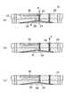
検査を開始した場合には、図10(a)に示すように、薬剤注入孔27から体液抽出部23へ体液排出促進薬剤αを送り、体液抽出部23内に体液排出促進薬剤αを充満させる。すなわち、開閉バルブ48、53を閉じたままで、切換バルブ42を薬剤供給機構33側と薬剤注入孔27側が連通する状態に切り替えた後、薬剤供給機構33を稼働して体液排出促進薬剤αを体液排出促進薬剤貯蔵部31から送り出す。体液排出促進薬剤αは薬剤流路32、34及び薬剤注入孔27を通って体液抽出部23に送られる。そして、体液抽出部23内に体液排出促進薬剤αが充満したら、薬剤供給機構33を停止し、切換バルブ42を閉じる。 When the examination is started, as shown in FIG. 10A, the bodily fluid discharge promoting drug α is sent from the
この状態をしばらく維持することにより、体液抽出部23内に保持された体液排出促進薬剤αは、体液排出部位γ内に浸透し経皮投与される。ピロカルピンまたはアセチルコリンを含有する体液排出促進薬剤αは皮下または体内からの発汗を促進するので、体液排出促進薬剤αを用いることで自然発汗の場合よりも体液の収集速度を速くし、体液の収集時間を短くできる。 By maintaining this state for a while, the bodily fluid discharge promoting drug α retained in the bodily
一般に、分子量が200以下の体液排出促進薬剤では受動拡散が支配的であり、皮膚表面に接触させ、あるいは塗布することにより受動的に皮膚吸収させることが可能である。しかし、分子量が200以上の体液排出促進薬剤については受動拡散が困難であり、物理的な方法によって吸収促進を考えなければならない。受動拡散だけでは薬剤透過性の改善に限りがあるから、体液排出促進薬剤と皮膚の間に電位差を生じさせることによってイオン性薬物の電気化学的ポテンシャルを上昇させ、能動的に体液排出促進薬剤を吸収拡散させる必要がある。皮膚に電気エネルギーを付与すると角質層は高い電気抵抗を示すので、主に汗腺や他の付属器官に電流が流れる。このとき体液排出促進薬剤としてイオン性薬物を用いていれば、体液排出促進薬剤もこれらの器官を通って皮下に吸収拡散させられると考えられる。 In general, a body fluid excretion promoting drug having a molecular weight of 200 or less is dominant in passive diffusion, and can be passively absorbed into the skin by contacting or applying to the skin surface. However, it is difficult to passively diffuse a body fluid discharge promoting drug having a molecular weight of 200 or more, and absorption promotion must be considered by a physical method. Since passive permeability alone has a limited improvement in drug permeability, by creating a potential difference between the fluid excretion promoting agent and the skin, the electrochemical potential of the ionic drug is increased, and the fluid excretion promoting agent is actively added. It is necessary to absorb and diffuse. When electrical energy is applied to the skin, the stratum corneum exhibits high electrical resistance, so that current flows mainly through sweat glands and other appendages. At this time, if an ionic drug is used as the body fluid excretion promoting agent, the body fluid excretion promoting agent is considered to be absorbed and diffused subcutaneously through these organs.
したがって、イオントフォレシス電源26や投与電極24、25を用いず、体液排出促進薬剤αを体液排出部位γに受動拡散(自然浸透)させることも可能である。しかし、本実施形態では、イオントフォレシス電源26や投与電極24、25を備えており、イオントフォレシス電源26によって投与電極24、25間に電圧を印加して体液排出部位γから体液排出促進薬剤αに電流を流すことで、体液排出促進薬剤αの皮下への浸透をより一層促進させるようにしている。よって、体液の収集速度を高めて体液の収集時間をより一層短縮することができる。 Therefore, it is also possible to passively diffuse (naturally permeate) the body fluid discharge promoting agent α into the body fluid discharge site γ without using the
こうして体液排出促進薬剤αを皮下に投与するのに必要な所定時間が経過したら、イオントフォレシス電源26をオフにし、図10(b)に示すように、体液抽出部23内に残っている体液排出促進薬剤αを排出する。体液抽出部23内の体液排出促進薬剤αを排出するには、開閉バルブ48を開き、薬剤回収機構45を稼働して体液抽出部23内の体液排出促進薬剤αを吸引し、この廃棄薬剤を廃棄薬剤貯蔵部47へ排出する。廃棄薬剤を排出し終えると、薬剤回収機構45を停止して開閉バルブ48を閉じる。 When the predetermined time necessary for subcutaneous administration of the body fluid discharge promoting agent α has elapsed, the
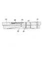
体液排出促進薬剤αを排出した直後には、図10(c)に示すように、検査部30や体液抽出部23は空になっているが、体液排出促進薬剤αを皮下に投与してから発汗が始まるまでの間には時間的な遅れがあるので、図11(a)に示すように、体液排出部位γから抽出された体液βがしだいに体液抽出部23内に溜まっていく。 Immediately after discharging the body fluid discharge promoting agent α, as shown in FIG. 10C, the
このように体液排出促進薬剤αを排出して空になった体液抽出部23に体液βを収集することで、体液βと体液排出促進薬剤αが混じったり、体液βが体液排出促進薬剤αで希釈されるのを回避でき、体液中の特定成分の測定精度を向上させることができる。特に、特定成分が低濃度の場合にも測定が可能になる。 By collecting the body fluid β in the body
体液抽出部23内に十分な体液βが溜まったら、開閉バルブ53を開いて体液回収機構50を稼働させ、図11(b)に示すように、体液抽出部23内に溜まった体液βを検査部30へ移動させて、あるいは検査部30を通過させて、検査部30において体液βの検査を行う。 When sufficient body fluid β is accumulated in the body
検査部30の通路上面には予め体液中の特定成分と特異的に反応する酵素57が固定化されており、図7又は図8に関して説明したような方法で検査を行う。例えば、酵素としてグルコースオキシダーゼ(GOD)又はグルコース脱水素酵素(GDH)を用いれば、体液中のグルコースの量(濃度)を測定することができ、検査結果を糖尿病検査などに用いることができる。 An
また、2又は3以上の検査部30を設け、一部の検査部30では酵素としてリジンオキシダーゼ(LOD)を固定化しておき、残りの検査部30では酵素としてグルコースオキシダーゼ(GOD)又はグルコース脱水素酵素(GDH)を固定化しておいてもよい。この場合には、リジンオキシダーゼによってリジンの量を検出することができるので、リジンを補正物質として測定することでグルコースの測定精度を高めることができる。 In addition, two or three or
測定に使用された体液β(廃棄体液)は、廃棄体液流路49、51を通って廃棄体液貯蔵部52に廃棄される。体液抽出部23及び検査部30内の体液βが排出されて空になったら、体液回収機構50を停止して開閉バルブ53を閉じる。 The body fluid β (waste body fluid) used for the measurement is discarded to the waste body
この結果、体液収集チップ22の内部は、図11(c)に示すように空になり、体液排出促進薬剤αや体液βを含まない検査開始当初の状態に戻る。よって、酵素の機能が持続する限り、体液分析装21を体液排出部位γから取り外すことなく連続して検査を行うことができる。酵素の寿命などによりセンサー機能が低下すれば、検査部カバー22cを体液収集チップ22から取り外し、酵素を固定化された新しい検査部カバー22cに取り換えることで、繰り返し検査を行うことができる。 As a result, the inside of the body
(第1の実施形態の変形例の説明)
図示しないが、体液排出促進薬剤を供給するための別な構造としては、体液排出促進薬剤貯蔵部31が、液体状の体液排出促進薬剤が封入された破断可能な液体容器(カプセル)であり、前記薬剤供給機構33が、体液排出促進薬剤貯蔵部31を破断するための破断具であってもよい。この場合には、薬剤供給機構33である破断具によって体液排出促進薬剤貯蔵部31を破断すると、体液排出促進薬剤貯蔵部31内の体液排出促進薬剤が薬剤注入孔27へ流れ出て、体液抽出部23に供給される。(Description of Modified Example of First Embodiment)
Although not shown in the drawings, as another structure for supplying the body fluid discharge promoting medicine, the body fluid discharge promoting
また、体液排出促進薬剤αを体液排出部位γに効率よく浸透させる方法としては、超音波振動を利用する方法がある。例えば、体液抽出部23の内面に圧電振動子などの超音波振動を発生する素子を設け、体液抽出部23内の体液排出促進薬剤αと体液排出部位γとの間に超音波振動を発生させるようにすればよい。体液抽出部23に体液排出促進薬剤αを供給した後、超音波振動を発生させると、その振動によって体液排出促進薬剤αの浸透が促進される。 Further, as a method for efficiently infiltrating the body fluid discharge promoting agent α into the body fluid discharge site γ, there is a method using ultrasonic vibration. For example, an element that generates ultrasonic vibration such as a piezoelectric vibrator is provided on the inner surface of the body
また、別な薬剤回収機構45(あるいは、体液抽出部23内の体液排出促進薬剤を体液抽出部23から排出する方法)としては、体液排出部位γから抽出される体液βの圧力によって体液排出促進薬剤αを体液抽出部23から押し出すようにしたものであってもよい。このような方法によれば、薬剤回収機構45に動力が必要なくなる。 Further, as another drug recovery mechanism 45 (or a method of discharging the bodily fluid discharge promoting drug in the bodily
また、体液抽出部23内の体液排出促進薬剤を体液抽出部23から排出する別な方法としては、体液抽出部23へ揮発性液体を送液し、揮発性液体を体液排出促進薬剤αと置換させ、あるいは揮発性液体を体液排出促進薬剤αに混合させ、その後、揮発性液体を揮発させるようにしてもよい。この方法によれば、揮発性液体を蒸発させることによって容易に体液抽出部を空にすることができる。 As another method for discharging the bodily fluid discharge promoting drug in the bodily
[第2の実施形態]
つぎに、本発明の実施形態2の体液分析装置66を説明する。
図12は、本発明の実施形態2による体液分析装置66の構成を示す概略断面図である。この実施形態は、実施形態1における薬剤供給機構33が、校正液供給機構40、薬剤回収機構45および体液回収機構50の働きを兼ねるようにしたものである。実施形態2の体液分析装置66は、実施形態1の体液分析装置21と同様な構造を有しているので、以下においては、主として異なる点だけを説明する。[Second Embodiment]
Next, the
FIG. 12 is a schematic cross-sectional view showing the configuration of the
この体液分析装置66では、体液回収機構50がないので、廃棄体液貯蔵部52は廃棄体液流路49に接続されている。同様に、薬剤回収機構45もないので、廃棄薬剤貯蔵部47は廃棄薬剤流路44に接続されている。 In this
体液排出促進薬剤貯蔵部31と薬剤供給機構33をつなぐ薬剤流路32には切換バルブ67が設けられており、切換バルブ67には空気流路36によって空気導入部35が接続され、また校正液流路39によって校正液貯蔵部38が接続されている。空気導入部35は、例えば大気に開放された通気孔である。切換バルブ67は、体液排出促進薬剤貯蔵部31側と薬剤供給機構33側が連通して空気導入部35側及び校正液貯蔵部38側が閉じた状態と、空気導入部35側と薬剤供給機構33側が連通して体液排出促進薬剤貯蔵部31側及び校正液貯蔵部38側が閉じた状態と、校正液貯蔵部38側と薬剤供給機構33側が連通して体液排出促進薬剤貯蔵部31側及び空気導入部35側が閉じた状態とに切り替え可能となっている。また、薬剤流路34には開閉バルブ43を設けている。 A switching
しかして、この実施形態にあっては、以下のようにして校正液や薬剤の供給・廃棄と体液の廃棄を行う。 Therefore, in this embodiment, the calibration liquid and the medicine are supplied / discarded and the body fluid is discarded as follows.
校正液を検査部30に送る場合には、開閉バルブ43を開き、切換バルブ67を校正液貯蔵部38側と薬剤供給機構33側が連通した状態に切り替えて薬剤供給機構33を稼働する。これによって校正液貯蔵部38内の校正液が送り出され、薬剤注入孔27及び体液抽出部23を経て校正液が検査部30内に供給される。 When sending the calibration liquid to the
校正液を排出する場合には、開閉バルブ43、53を開き、切換バルブ67を空気導入部35側と薬剤供給機構33側が連通した状態に切り替えて薬剤供給機構33を稼働する。これによって薬剤注入孔27に空気を注入することができ、体液抽出部23及び検査部30内の校正液が空気圧で押し出されて、廃棄体液貯蔵部52へ廃棄される。 When discharging the calibration liquid, the opening /
体液排出促進薬剤αを体液抽出部23に供給する場合には、開閉バルブ43を開き、切換バルブ67を体液排出促進薬剤貯蔵部31側と薬剤供給機構33側が連通した状態に切り替えて薬剤供給機構33を稼働する。これによって体液排出促進薬剤貯蔵部31内の体液排出促進薬剤αが送り出され、薬剤注入孔27を通って体液排出促進薬剤αが体液抽出部23内に供給される。 When supplying the bodily fluid discharge promoting medicine α to the bodily
体液排出促進薬剤αを排出する場合には、開閉バルブ43、48を開き、切換バルブ67を空気導入部35側と薬剤供給機構33側が連通した状態に切り替えて薬剤供給機構33を稼働する。これによって薬剤注入孔27に空気を注入することができ、体液抽出部23内の廃棄薬剤が空気圧で押し出されて、廃棄薬剤貯蔵部47へ廃棄される。 When the body fluid discharge promoting medicine α is discharged, the opening and closing
体液抽出部23及び検査部30内の廃棄体液を排出する場合には、開閉バルブ43、53を開き、切換バルブ67を空気導入部35側と薬剤供給機構33側が連通した状態に切り替えて薬剤供給機構33を稼働する。これによって薬剤注入孔27に空気を注入することができ、体液抽出部23及び検査部30内の体液βが空気圧で押し出されて、廃棄体液貯蔵部52へ廃棄される。 When discharging the waste body fluid in the body
よって、この体液分析装置66によれば、体液回収機構50や薬剤回収機構45を無くすことができるので、体液分析装置66の構造を簡略化してコストを安価にすることができるとともに、体液分析装置66の小型化を図ることができる。 Therefore, according to the
[第3の実施形態]
つぎに、本発明の実施形態3による体液分析装置71を説明する。
図13は、本発明の実施形態3による体液分析装置71の構成を示す概略断面図である。図14は、この体液分析装置71において体液排出促進薬剤を供給・廃棄し、また体液を廃棄するための構成を示す図である。また、図15は、体液分析装置71を被験者の腕に装着した様子を示す斜視図である。[Third Embodiment]
Next, a
FIG. 13 is a schematic cross-sectional view showing a configuration of a
実施形態3は、実施形態2において廃棄薬剤を廃棄体液貯蔵部52へ廃棄する(あるいは、体液排出促進薬剤貯蔵部31へ回収する)ようにしたものであり、それによってさらに薬剤回収孔28、廃棄薬剤流路44、廃棄薬剤貯蔵部47を不要にしている。
なお、図13及び図14においては、校正液貯蔵部38を図示省略しているが、校正液を用いる必要がある場合には、実施形態2の場合と同じように、校正液貯蔵部38を切換バルブ67に切り替え可能に接続しておき、実施形態2と同様にして校正液を供給及び回収すればよい。In the third embodiment, the waste medicine is discarded to the waste body fluid storage section 52 (or recovered to the body fluid discharge promoting medicine storage section 31) in the second embodiment. The
In FIG. 13 and FIG. 14, the calibration
実施形態3にあっては、実施形態2の場合と同様にして、体液排出促進薬剤貯蔵部31内の体液排出促進薬剤αを体液抽出部23へ供給することができる。 In the third embodiment, the bodily fluid discharge promoting drug α in the bodily fluid discharge promoting
体液抽出部23内に残留した体液排出促進薬剤αを排出する場合には、開閉バルブ43、53を開き、切換バルブ67を空気導入部35側と薬剤供給機構33側が連通した状態に切り替えて薬剤供給機構33を稼働する。これによって薬剤注入孔27に空気を注入することができ、体液抽出部23内の廃棄薬剤が空気圧で押し出されて、検査部30を通過して廃棄体液貯蔵部52へ廃棄される。 When discharging the bodily fluid discharge promoting medicine α remaining in the bodily
別な方法としては、開閉バルブ43を開いて薬剤供給機構33で体液抽出部23内の体液排出促進薬剤αを吸引し、使用した体液排出促進薬剤αを体液排出促進薬剤貯蔵部31へ回収するようにしてもよい。この方法によれば、体液排出促進薬剤αを再利用することができるので、体液排出促進薬剤αの消費量を少なくできる。 As another method, the on-off
体液抽出部23及び検査部30内の廃棄体液を排出する場合には、実施形態2の場合と同様に、体液抽出部23及び検査部30内の体液βを空気圧で押し出し、廃棄体液貯蔵部52へ廃棄することができる。 When the waste body fluid in the body
よって、この体液分析装置71によれば、さらに薬剤回収孔28や廃棄薬剤貯蔵部47などを無くすことができるので、体液分析装置66の構造を一層簡略化してコストを安価にすることができるとともに、体液分析装置66をさらに小型化することができる。 Therefore, according to the
また、実施形態3の体液分析装置71では、体液収集チップ22内に金属等の導電性材料からなる管27aを上下方向に沿って埋め込み、管27aによって薬剤注入孔27を形成し、管27aの下端を投与電極24に電気的に接触させている。また、イオントフォレシス電源26の一方の出力端子を管27aに接続している。よって、この実施形態では、管27aを介して投与電極24、25間に電圧を印加することができる。 In the
また、この体液分析装置71は、体液抽出部23、投与電極24、投与電極25、薬剤注入孔27、体液送出路29および検査部30を設けられた体液収集チップ22(すなわち、体液収集部)と、体液排出促進薬剤貯蔵部31、薬剤供給機構33、廃棄体液貯蔵部52、開閉バルブ43、53、イオントフォレシス電源26、薬剤供給機構33を駆動するための電池などを設けられた分析装置本体72とに分かれている。 In addition, the
分析装置本体72は、図13及び図15に示すように、ケーシング73内に納められていて、バンド74によって被験者の腕に装着できるようになっている。さらに、分析装置本体72には、検査結果等を表示するための表示部76と、検査スタートを入力したり、表示を切り替えたりするための操作ボタン77を設けている。 As shown in FIGS. 13 and 15, the analyzer
体液収集チップ22は、チップ挿入部75から分析装置本体72内に装着でき、また72から分離することができる。体液収集チップ22を分析装置本体72に装着した状態では、図13のように体液収集チップ22の下面が体液排出部位γに密着するようになる。また、体液収集チップ22を分析装置本体72内に装着した状態では、イオントフォレシス電源26の出力端子が管27aと投与電極25の上面に接触し、薬剤供給用の薬剤流路34が薬剤注入孔27に接続され、体液回収用の廃棄体液流路49が体液送出路29に接続される。
なお、体液排出促進薬剤貯蔵部31や廃棄体液貯蔵部52は、体液収集チップ22上に設けてあってもよい。また、検査部30を分析装置本体72に設けることも可能である。The body
The body fluid discharge promoting
このような構成によれば、分析装置本体72を被験者の腕などに装着したままで、連続して複数回の検査を行うことができる。例えば、体液の回収のみであれば、体液収集チップ22を取り換えなくても繰り返して体液収集を行えるし、検査を行う場合でも、酵素の機能が持続する限り、体液収集チップ22を取り換えることなく連続して複数回の検査を行うことができる。また、酵素の働きが弱くなった場合でも、体液収集チップ22もしくは検査部カバー22cを取り換えるだけで、検査を続けることができる。 According to such a configuration, it is possible to perform a plurality of tests continuously while the analyzer
(第3の実施形態の変形例の説明)
まず、一方の投与電極24の変形例をいくつか示す。
図16に示す変形例では、体液抽出部23の内壁面に設けていた導電膜を除去し、薬剤注入孔27を形成するための管27aを導電性材料によって形成している。そして、この管27aにイオントフォレシス電源26の出力端子を接続することで、管27aを一方の投与電極24として用いている。管27aの下端は体液抽出部23の内壁面に達しているので、投与電極24である管27aによって体液抽出部23内の体液排出促進薬剤に電圧を印加することができる。(Description of Modified Example of Third Embodiment)
First, some modifications of one
In the modification shown in FIG. 16, the conductive film provided on the inner wall surface of the body
また、導電材料からなる管27aは、図17に示すように、その下端が体液抽出部23に達していなくても差し支えない。管27aが短くても、薬剤注入孔27内に残っている体液排出促進薬剤αを通じて体液抽出部23内の体液排出促進薬剤αに電圧を印加することができるからである。 Moreover, as shown in FIG. 17, the
また、図18に示す変形例のように、体液抽出部23の内壁面に設けていた導電膜を除去し、薬剤注入孔27とは別な位置に一方の投与電極24を設けてもよい。 Further, as in the modification shown in FIG. 18, the conductive film provided on the inner wall surface of the body
もっとも、図16〜図18に示したような電極構造であると、体液抽出部23内や薬剤注入孔27内の一部に気泡が発生した場合、気泡によって投与電極24と体液排出促進薬剤αとが電気的に分離されて体液排出促進薬剤に電圧を印加できなくなるおそれがある。したがって、投与電極24は実施形態3(図13)のように体液排出促進薬剤との接触面積がある程度大きなものが望ましい。 However, in the case of the electrode structure as shown in FIGS. 16 to 18, when bubbles are generated in the body
つぎに、他方の投与電極25は、図19に示す変形例のように、体液収集チップ22内でなく、分析装置本体72に設けてもよい。また、図20に示すように、投与電極25を分析装置本体72の外部において、被験者に接触するように設けてもよい。 Next, the
なお、図16〜図20に示したような電極構造は、他の実施形態においても適用できるものである。 The electrode structure as shown in FIGS. 16 to 20 can be applied to other embodiments.
また、実施形態3のさらに別な変形例としては、実施形態3のように分析装置本体72と体液収集チップ22とに分離せず、体液排出部位に装着するための体液収集チップ22に、体液抽出部23、薬剤供給機構33、検査部30、廃棄体液貯蔵部52などすべての構成を設けて体液分析装置を一体型とすることも可能である。 Further, as yet another modification of the third embodiment, the body
[第4の実施形態]
図21は本発明の実施形態4による体液分析装置81を示す斜視図である。図22は実施形態4による体液分析装置81の構造を示す概略断面図である。[Fourth Embodiment]
FIG. 21 is a perspective view showing a
実施形態4の体液分析装置81では、体液収集チップ22に形成された体液収集部と分析装置本体72とを別々に構成し、体液収集チップ22にバンド74を設けて被験者の腕などに装着できるようにし、分析装置本体72を据え置き型としたものである。 In the
かかる実施形態によれば、被験者に装着する液体収集部を小型軽量化することができる。 According to this embodiment, the liquid collection part with which a test subject is mounted can be reduced in size and weight.
[第5の実施形態]
図23は本発明の実施形態5による体液分析装置82の構造を示す概略断面図である。[Fifth Embodiment]
FIG. 23 is a schematic sectional view showing the structure of a
この体液分析装置82では、校正液を検査部30に供給する場合や、体液排出促進薬剤を体液抽出部23に供給する場合には、シリンジや注射器を用いて薬剤注入孔27から手作業で注入する。 In this
また、校正液、体液排出促進薬剤、体液を回収する場合には、廃棄体液流路49に設けた体液回収機構50を用いて吸引し、廃棄体液貯蔵部52へ廃棄する。 Further, when collecting the calibration fluid, the bodily fluid discharge promoting medicine, and the bodily fluid, they are sucked using the bodily
かかる実施形態によれば、体液分析装置82の構造を簡素化して、体液分析装置82を低コスト化することができる。 According to this embodiment, the structure of the
本発明は、汗などの体液を収集する体液収集装置として実施できる。また、体液に含まれる特定成分を分析する体液分析装置として実施できる。さらに、糖尿病等の疾病の診断用の医療機器として用いることができる。 The present invention can be implemented as a body fluid collection device that collects body fluid such as sweat. Moreover, it can implement as a body fluid analyzer which analyzes the specific component contained in a body fluid. Furthermore, it can be used as a medical device for diagnosing diseases such as diabetes.
21、66、71、81、82 体液分析装置
22 体液収集チップ
23 体液抽出部
24、25 投与電極
27 薬剤注入孔
27a 管
28 薬剤回収孔
29 体液送出路
30 検査部
31 体液排出促進薬剤貯蔵部
33 薬剤供給機構
35 空気導入部
36 空気流路
38 校正液貯蔵部
40 校正液供給機構
45 薬剤回収機構
47 廃棄薬剤貯蔵部
50 体液回収機構
52 廃棄体液貯蔵部
57 酵素
58 発色色素
72 分析装置本体
74 バンド
α 体液排出促進薬剤
β 体液
γ 体液排出部位21, 66, 71, 81, 82
Claims (34)
Translated fromJapanese皮下または体内から体液を排出させるための体液排出促進薬剤を体液排出部位上で保持する機能、および体液排出促進薬剤が投与された部位から抽出される体液の収集を行う機能を有する体液抽出部と、
前記体液抽出部で一端が開口した、体液排出促進薬剤を回収または廃棄するための薬剤回収通路と、
皮下または体内へ投与した後に前記体液抽出部に残った体液排出促進薬剤を、前記薬剤回収通路を通じて回収または廃棄するための薬剤回収機構と、
を備えた体液収集装置。A bodily fluid collection device that extracts and collects bodily fluid from a subject's skin or body,
A bodily fluid extraction unit having a function of holding a bodily fluid discharge promoting drug for discharging bodily fluid from the subcutaneous body or the body, and a function of collecting bodily fluid extracted from the site to which the bodily fluid discharge promoting drug is administered; ,
A drug collection passage for collecting or discarding a bodily fluid discharge promoting drug, one end of which is opened in the bodily fluid extraction unit;
A drug recovery mechanism for recovering or discarding the bodily fluid discharge promoting drug remaining in the bodily fluid extraction unit after being administered subcutaneously or into the body, through the drug recovery path;
A body fluid collecting device.
前記体液排出促進薬剤貯蔵部に貯蔵された体液排出促進薬剤を前記薬剤注入通路から前記体液抽出部に供給するための薬剤供給機構と、
をさらに備えた、請求項2に記載の体液収集装置。A body fluid discharge promoting drug storage unit for storing the body fluid discharge promoting drug;
A drug supply mechanism for supplying the bodily fluid discharge promoting drug stored in the bodily fluid discharge promoting drug storage unit to the bodily fluid extraction unit from the drug injection passage;
The bodily fluid collection device according to claim 2, further comprising:
前記薬剤供給機構がポンプである、
ことを特徴とする、請求項3に記載の体液収集装置。The body fluid discharge promoting drug is a liquid;
The drug supply mechanism is a pump;
The body fluid collecting device according to claim 3, wherein
前記体液排出促進薬剤貯蔵部が、体液排出促進薬剤を封入した破断可能な液体容器であり、
前記薬剤供給機構が、前記液体容器を破断するための破断具である、
ことを特徴とする、請求項3に記載の体液収集装置。The body fluid discharge promoting drug is a liquid,
The bodily fluid discharge promoting drug storage unit is a breakable liquid container enclosing the bodily fluid discharge promoting drug,
The drug supply mechanism is a breaking tool for breaking the liquid container.
The body fluid collecting device according to claim 3, wherein
前記薬剤回収機構は、ポンプを用いて前記体液抽出部へ送入される空気により体液排出促進薬剤を押し出す方法、皮下もしくは体内から前記体液抽出部へ排出される体液により体液排出促進薬剤を押し出す方法、または、ポンプを用いて体液排出促進薬剤を吸引する方法のうちから選択されたいずれかの方法により、体液排出促進薬剤を前記体液抽出部から回収または廃棄するものである、
ことを特徴とする、請求項1に記載の体液収集装置。The body fluid discharge promoting drug is a liquid;
The drug recovery mechanism is a method of pushing out a bodily fluid discharge promoting drug by air sent to the bodily fluid extraction unit using a pump, a method of pushing out a bodily fluid discharge promoting drug by bodily fluid discharged from the subcutaneous body or the body to the bodily fluid extraction unit Or, the body fluid discharge promoting agent is collected or discarded from the body fluid extraction unit by any method selected from the methods of sucking the body fluid discharge promoting agent using a pump.
The body fluid collecting device according to claim 1, wherein
前記薬剤回収機構は、前記体液抽出部へ揮発性液体を送入し、体液排出促進薬剤と置換もしくは混合し、揮発性液体を揮発させることにより前記体液排出促進薬剤を前記体液抽出部から廃棄するものであることを特徴とする、請求項1に記載の体液収集装置。The body fluid discharge promoting drug is a liquid,
The medicine recovery mechanism sends the volatile liquid into the body fluid extraction unit, replaces or mixes with the body fluid discharge promoting medicine, and discards the body fluid discharge promotion medicine from the body fluid extraction section by volatilizing the volatile liquid. The body fluid collecting device according to claim 1, wherein the body fluid collecting device is a thing.
前記体液抽出部に収集された体液を、前記体液回収通路を通じて回収するための体液回収機構をさらに備えた、請求項1に記載の体液収集装置。A bodily fluid collection passage for collecting bodily fluid, one end of which is opened in the bodily fluid extraction unit;
The bodily fluid collection device according to claim 1, further comprising a bodily fluid collection mechanism for collecting bodily fluid collected in the bodily fluid extraction unit through the bodily fluid collection passage.
前記体液抽出部に保持された体液排出促進薬剤と接触するようにして、かつ、前記薬剤注入通路と異なる位置において、前記投与電極のうちのいずれか一つの投与電極を設けた、請求項12に記載の体液収集装置。A drug injection passage for injecting a bodily fluid discharge promoting drug into the bodily fluid extraction unit;
13. The administration electrode according to claim 12, wherein any one of the administration electrodes is provided so as to come into contact with the body fluid discharge promoting medicine held in the body fluid extraction unit and at a position different from the medicine injection passage. The body fluid collecting device as described.
皮下または体内から抽出して収集される体液は汗である、
ことを特徴とする、請求項1に記載の体液収集装置。The fluid excretion promoting drug is a drug containing pilocarpine or acetylcholine,
The bodily fluid that is collected subcutaneously or extracted from the body is sweat,
The body fluid collecting device according to claim 1, wherein
前記体液収集装置を体液排出部位に装着した後、
前記体液抽出部に保持された体液排出促進薬剤を皮下または体内に投与するプロセスと、
前記薬剤回収機構によって前記体液抽出部に残った体液排出促進薬剤を除去するプロセスと、
体液排出促進薬剤が投与された部位から抽出される体液を前記体液抽出部で収集するプロセスとを、前記体液収集装置により順次実行することを特徴とする、体液収集方法。A method of collecting bodily fluid using the bodily fluid collecting device according to claim 1,
After mounting the body fluid collection device on the body fluid discharge site,
A process of administering the bodily fluid discharge promoting drug held in the bodily fluid extraction unit subcutaneously or into the body;
A process of removing the bodily fluid discharge promoting drug remaining in the bodily fluid extraction unit by the drug collecting mechanism;
A method for collecting bodily fluids extracted from a site to which a bodily fluid discharge promoting drug is administered is collected by the bodily fluid extracting unit in order by the bodily fluid collecting device.
請求項1に記載した体液収集装置を、被験者の皮下または体内から収集するための体液収集部として備え、
前記体液収集部に設けた前記体液抽出部で収集した体液中の特定成分を検出または測定するための検査部をさらに備えた体液分析装置。A body fluid analyzer for detecting or measuring a specific component in a body fluid collected from a subject's skin or inside the body,
The bodily fluid collection device according to claim 1 is provided as a bodily fluid collection unit for collecting from a subject's subcutaneous body or body,
A body fluid analyzer further comprising an inspection unit for detecting or measuring a specific component in the body fluid collected by the body fluid extraction unit provided in the body fluid collection unit.
体液中の特定成分と酵素の間で起こる反応により生じる電流に基づく信号を、前記検査電極で検出することにより体液中の特定成分を検出または測定することを特徴とする、請求項19に記載の体液分析装置。The test part is composed of an enzyme and a test electrode that react specifically with a specific component in a body fluid,
The specific component in the body fluid is detected or measured by detecting a signal based on a current generated by a reaction occurring between the specific component in the body fluid and the enzyme with the test electrode. Body fluid analyzer.
体液中の特定成分と前記酵素及び前記発色色素との呈色反応を光学的に検出することにより体液中の特定成分を検出または測定することを特徴とする、請求項19に記載の体液分析装置。The inspection unit consists of an enzyme that reacts specifically with a specific component in a body fluid and a coloring dye,
20. The body fluid analyzer according to claim 19, wherein the body fluid analyzer detects or measures a specific component in the body fluid by optically detecting a color reaction between the specific component in the body fluid and the enzyme and the coloring dye. .
前記検査部はそれぞれ互いに異なる種類の酵素を有する、請求項20または21に記載の体液分析装置。Two or more inspection units are provided,
The body fluid analyzer according to claim 20 or 21, wherein the inspection units have different types of enzymes.
前記検査部はそれぞれ同一種類の酵素を有する、請求項20または21に記載の体液分析装置。Two or more inspection units are provided,
The body fluid analyzer according to claim 20 or 21, wherein each of the inspection units has the same type of enzyme.
互いに異なる種類の酵素を有する検査部の組合せを1セットとし、前記1セットの検査部を複数セット有する、請求項20または21に記載の体液分析装置。Comprising four or more inspection sections,
The body fluid analyzer according to claim 20 or 21, wherein a combination of the inspection units having different types of enzymes is set as one set, and the plurality of sets of the one test unit are included.
前記校正液貯蔵部に貯蔵された校正液を前記検査部に供給するための校正液供給機構とを備えた、請求項19に記載の体液分析装置。A calibration solution storage unit for storing a calibration solution for calibrating the inspection unit;
The body fluid analyzer according to claim 19, further comprising a calibration liquid supply mechanism for supplying the calibration liquid stored in the calibration liquid storage unit to the inspection unit.
検査後の体液を廃棄するための廃棄体液貯蔵部と、
前記体液抽出部に収集された体液を、前記体液回収通路を通じて回収し、前記検査部による検査後の体液を前記廃棄体液貯蔵部へ廃棄するための体液回収機構と、
をさらに備えた、請求項19に記載の体液分析装置。A bodily fluid collection passage for collecting bodily fluid, one end of which is opened in the bodily fluid extraction unit;
A waste body fluid storage unit for discarding the body fluid after the inspection;
A bodily fluid collection mechanism for collecting bodily fluid collected in the bodily fluid extraction unit through the bodily fluid collection passage and discarding bodily fluid after the examination by the examination unit into the waste bodily fluid storage unit;
The body fluid analyzer according to claim 19, further comprising:
検査後の体液を廃棄するための廃棄体液貯蔵部と、
前記体液抽出部に収集された体液を回収し、前記検査部による検査後の体液を前記廃棄体液貯蔵部へ廃棄するための体液回収機構と、
をさらに備えた、請求項19に記載の体液分析装置。A drug supply mechanism for supplying the bodily fluid discharge promoting drug stored in the bodily fluid discharge promoting drug storage unit to the bodily fluid extraction unit;
A waste body fluid storage unit for discarding the body fluid after the inspection;
A body fluid collection mechanism for collecting the body fluid collected in the body fluid extraction unit, and discarding the body fluid after the inspection by the inspection unit to the waste body fluid storage unit;
The body fluid analyzer according to claim 19, further comprising:
前記体液収集チップは、前記体液抽出部および前記検査部を備え、
前記分析装置本体は、前記薬剤供給機構、前記薬剤回収機構、前記体液回収機構および前記廃棄体液貯蔵部を備えていることを特徴とする、請求項29に記載の体液分析装置。Consists of a bodily fluid collection chip for mounting on the bodily fluid discharge site, and a stationary analyzer main body,
The body fluid collection chip includes the body fluid extraction unit and the inspection unit,
30. The body fluid analyzer according to claim 29, wherein the analyzer main body includes the medicine supply mechanism, the medicine recovery mechanism, the body fluid recovery mechanism, and the waste body fluid storage unit.
前記体液収集チップは、前記体液抽出部および前記検査部を備え、
前記分析装置本体は、前記薬剤供給機構、前記薬剤回収機構、前記体液回収機構および前記廃棄体液貯蔵部を備えていることを特徴とする、請求項29に記載の体液分析装置。It consists of an analyzer main body to be attached to a body fluid discharge site, and a body fluid collection chip that can be detachably attached to the analyzer main body.
The body fluid collection chip includes the body fluid extraction unit and the inspection unit,
30. The body fluid analyzer according to claim 29, wherein the analyzer main body includes the medicine supply mechanism, the medicine recovery mechanism, the body fluid recovery mechanism, and the waste body fluid storage unit.
Priority Applications (5)
| Application Number | Priority Date | Filing Date | Title |
|---|---|---|---|
| JP2009013126AJP2010167130A (en) | 2009-01-23 | 2009-01-23 | Body fluid collection apparatus and body fluid analyzer |
| CN201080005281XACN102292020A (en) | 2009-01-23 | 2010-01-21 | Efficient body fluid collection device and high-precision body fluid analysis device |
| DE112010000750TDE112010000750T5 (en) | 2009-01-23 | 2010-01-21 | Body fluid collection device for efficient collection of body fluid and fluid analyzer for accurate analysis |
| PCT/JP2010/050717WO2010084917A1 (en) | 2009-01-23 | 2010-01-21 | Bodily fluid collection device enabling efficient bodily fluid collection and bodily fluid analysis device enabling accurate analysis |
| US13/183,172US20110275918A1 (en) | 2009-01-23 | 2011-07-14 | Body fluid collecting device for efficiently collecting body fluid and body fluid analyzer for accurate analysis |
Applications Claiming Priority (1)
| Application Number | Priority Date | Filing Date | Title |
|---|---|---|---|
| JP2009013126AJP2010167130A (en) | 2009-01-23 | 2009-01-23 | Body fluid collection apparatus and body fluid analyzer |
Publications (1)
| Publication Number | Publication Date |
|---|---|
| JP2010167130Atrue JP2010167130A (en) | 2010-08-05 |
Family
ID=42355969
Family Applications (1)
| Application Number | Title | Priority Date | Filing Date |
|---|---|---|---|
| JP2009013126AWithdrawnJP2010167130A (en) | 2009-01-23 | 2009-01-23 | Body fluid collection apparatus and body fluid analyzer |
Country Status (5)
| Country | Link |
|---|---|
| US (1) | US20110275918A1 (en) |
| JP (1) | JP2010167130A (en) |
| CN (1) | CN102292020A (en) |
| DE (1) | DE112010000750T5 (en) |
| WO (1) | WO2010084917A1 (en) |
Cited By (4)
| Publication number | Priority date | Publication date | Assignee | Title |
|---|---|---|---|---|
| WO2021106524A1 (en)* | 2019-11-26 | 2021-06-03 | 航平 石濱 | Detection device and detector |
| JP2022519919A (en)* | 2019-03-18 | 2022-03-25 | コーニンクレッカ フィリップス エヌ ヴェ | Sweat sensing system |
| JP2023518112A (en)* | 2020-05-11 | 2023-04-27 | コーニンクレッカ フィリップス エヌ ヴェ | Calibration using reclaimed surface |
| JP2023538784A (en)* | 2020-08-31 | 2023-09-11 | コーニンクレッカ フィリップス エヌ ヴェ | sweat detection device |
Families Citing this family (39)
| Publication number | Priority date | Publication date | Assignee | Title |
|---|---|---|---|---|
| WO2011156095A2 (en) | 2010-06-10 | 2011-12-15 | The Regents Of The University Of California | Textile-based printable electrodes for electrochemical sensing |
| CA2869469A1 (en)* | 2012-04-04 | 2013-10-10 | University Of Cincinnati | Sweat simulation, collection and sensing systems |
| CN103932718B (en)* | 2013-01-17 | 2015-12-02 | 北京怡成生物电子技术股份有限公司 | The portable monitoring system of thing is analyzed in dynamic METHOD FOR CONTINUOUS DETERMINATION body fluid |
| WO2014108087A1 (en)* | 2013-01-09 | 2014-07-17 | 北京怡成生物电子技术有限公司 | Portable monitoring system for dynamically and continuously measuring analyte in body liquid |
| JP2016533227A (en) | 2013-10-18 | 2016-10-27 | ユニバーシティ・オブ・シンシナティ | Sweat perception with a guarantee over time |
| CN105848564B (en)* | 2013-10-18 | 2020-12-25 | 辛辛那提大学 | Device for integrated, repeated, prolonged, and/or reliable sweat stimulation and biosensing |
| US10888244B2 (en) | 2013-10-18 | 2021-01-12 | University Of Cincinnati | Sweat sensing with chronological assurance |
| EP3148430A4 (en) | 2014-05-28 | 2018-05-16 | University of Cincinnati | Advanced sweat sensor adhesion, sealing, and fluidic strategies |
| EP3148420A4 (en) | 2014-05-28 | 2018-09-19 | University of Cincinnati | Sweat monitoring and control of drug delivery |
| EP3148416B8 (en) | 2014-05-28 | 2024-04-17 | University of Cincinnati | Devices with reduced sweat volumes between sensors and sweat glands |
| CA2962340A1 (en)* | 2014-09-22 | 2016-03-31 | University Of Cincinnati | Sweat sensing with analytical assurance |
| EP3244348A1 (en)* | 2014-10-15 | 2017-11-15 | Eccrine Systems, Inc. | Sweat sensing device communication, security and compliance |
| US10722160B2 (en) | 2014-12-03 | 2020-07-28 | The Regents Of The University Of California | Non-invasive and wearable chemical sensors and biosensors |
| KR20160089718A (en) | 2015-01-20 | 2016-07-28 | 삼성전자주식회사 | Sensor module and wearable analyzing device for body compositon with the same |
| CN111067544B (en) | 2015-02-13 | 2023-04-07 | 辛辛那提大学 | Device integrating indirect sweat stimulation and sensing |
| US20180263538A1 (en)* | 2015-02-24 | 2018-09-20 | Eccrine Systems, Inc. | Dynamic sweat sensing device management |
| US10646142B2 (en) | 2015-06-29 | 2020-05-12 | Eccrine Systems, Inc. | Smart sweat stimulation and sensing devices |
| WO2017019602A1 (en)* | 2015-07-24 | 2017-02-02 | University Of Cincinnati | Reduced sample volume for sensing of analytes generated by reverse iontophoresis |
| WO2017070640A1 (en) | 2015-10-23 | 2017-04-27 | Eccrine Systems, Inc. | Devices capable of sample concentration for extended sensing of sweat analytes |
| US20180340903A1 (en)* | 2015-10-30 | 2018-11-29 | University Of Cincinnati | Sweat sensing devices with electromagnetically shielded sensors, interconnects, and electronics |
| US10674946B2 (en) | 2015-12-18 | 2020-06-09 | Eccrine Systems, Inc. | Sweat sensing devices with sensor abrasion protection |
| US10471249B2 (en) | 2016-06-08 | 2019-11-12 | University Of Cincinnati | Enhanced analyte access through epithelial tissue |
| WO2018006087A1 (en) | 2016-07-01 | 2018-01-04 | University Of Cincinnati | Devices with reduced microfluidic volume between sensors and sweat glands |
| EP3487390A4 (en) | 2016-07-19 | 2020-03-11 | Eccrine Systems, Inc. | Sweat conductivity, volumetric sweat rate and galvanic skin response devices and applications |
| EP3500339B1 (en) | 2016-08-19 | 2021-10-27 | University of Cincinnati | Prolonged sweat stimulation |
| CN106225865A (en)* | 2016-09-09 | 2016-12-14 | 王行环 | A kind of operative drainage liquid measure monitor device |
| US10736565B2 (en) | 2016-10-14 | 2020-08-11 | Eccrine Systems, Inc. | Sweat electrolyte loss monitoring devices |
| US12109032B1 (en) | 2017-03-11 | 2024-10-08 | Biolinq Incorporated | Methods for achieving an isolated electrical interface between an anterior surface of a microneedle structure and a posterior surface of a support structure |
| US11045142B1 (en) | 2017-04-29 | 2021-06-29 | Biolinq, Inc. | Heterogeneous integration of silicon-fabricated solid microneedle sensors and CMOS circuitry |
| EP3713479B1 (en)* | 2017-11-22 | 2023-09-20 | Epicore Biosystems, Inc. | Wearable fluidic device and system for sweat collection and extraction |
| US20210338117A1 (en)* | 2018-09-05 | 2021-11-04 | Kwangwoon University Industry-Academic Collaboration Foundation | Blood glucose measurement device and blood glucose measurement system using same |
| SE2251496A1 (en) | 2020-07-29 | 2022-12-20 | Biolinq Incorporated | Continuous analyte monitoring system with microneedle array |
| US11707262B2 (en)* | 2020-09-25 | 2023-07-25 | United States Of America As Represented By The Secretary Of The Air Force | Systems and methods for real-time sweat sampling and analysis |
| CN116367772A (en)* | 2020-10-19 | 2023-06-30 | 可口可乐公司 | Novel non-clogging sweat sensing device and method of making the same |
| CA3184224A1 (en) | 2021-05-08 | 2022-11-17 | Joshua Ray Windmiller | Fault detection for microneedle array based continuous analyte monitoring device |
| CN114041787B (en)* | 2021-09-30 | 2024-01-23 | 曾宇希 | Noninvasive blood glucose monitoring device and wearable noninvasive blood glucose meter |
| US11559225B1 (en) | 2021-12-30 | 2023-01-24 | Epicore Biosystems, Inc. | Wearable biofluid volume and composition measurement system |
| US12336816B2 (en) | 2023-02-02 | 2025-06-24 | Biolinq Incorporated | Method for improved sensor sensitivity of a microneedle-based continuous analyte monitoring system |
| WO2025090609A1 (en)* | 2023-10-24 | 2025-05-01 | Abbott Diabetes Care Inc. | Systems, devices, and methods for analyte monitoring |
Family Cites Families (12)
| Publication number | Priority date | Publication date | Assignee | Title |
|---|---|---|---|---|
| US4383529A (en) | 1980-11-03 | 1983-05-17 | Wescor, Inc. | Iontophoretic electrode device, method and gel insert |
| US4542751A (en) | 1982-03-15 | 1985-09-24 | Wescor, Inc. | Sweat-collecting device and method |
| JPH095256A (en) | 1995-06-19 | 1997-01-10 | Sony Corp | Detecting method of foreign substance on surface of metal |
| JPH095296A (en) | 1995-06-23 | 1997-01-10 | Brother Ind Ltd | Biosensor |
| JPH0951877A (en)* | 1995-08-11 | 1997-02-25 | Nobuyuki Tsutsui | Perspiration recorder |
| EP1411352B1 (en)* | 2001-07-13 | 2012-01-11 | ARKRAY, Inc. | Analysing instrument and lancet-integrated attachment for concentration measuring device |
| GB0120202D0 (en)* | 2001-08-18 | 2001-10-10 | Psimedica | Body fluid collection and analysis |
| DE10163972B4 (en)* | 2001-12-22 | 2005-10-27 | Roche Diagnostics Gmbh | Method and device for determining a light transport parameter and an analyte in a biological matrix |
| JP2004016609A (en)* | 2002-06-19 | 2004-01-22 | Omron Healthcare Co Ltd | Method and apparatus for measuring concentration of bodily fluid component |
| JP4647324B2 (en) | 2004-02-03 | 2011-03-09 | シスメックス株式会社 | Analyzer, cartridge and cartridge kit |
| JP2008504881A (en)* | 2004-07-01 | 2008-02-21 | ヴィヴォメディカル, インコーポレイテッド | Noninvasive glucose measurement |
| US20070027383A1 (en)* | 2004-07-01 | 2007-02-01 | Peyser Thomas A | Patches, systems, and methods for non-invasive glucose measurement |
- 2009
- 2009-01-23JPJP2009013126Apatent/JP2010167130A/ennot_activeWithdrawn
- 2010
- 2010-01-21DEDE112010000750Tpatent/DE112010000750T5/ennot_activeWithdrawn
- 2010-01-21CNCN201080005281XApatent/CN102292020A/enactivePending
- 2010-01-21WOPCT/JP2010/050717patent/WO2010084917A1/enactiveApplication Filing
- 2011
- 2011-07-14USUS13/183,172patent/US20110275918A1/ennot_activeAbandoned
Cited By (8)
| Publication number | Priority date | Publication date | Assignee | Title |
|---|---|---|---|---|
| JP2022519919A (en)* | 2019-03-18 | 2022-03-25 | コーニンクレッカ フィリップス エヌ ヴェ | Sweat sensing system |
| JP7061237B2 (en) | 2019-03-18 | 2022-04-27 | コーニンクレッカ フィリップス エヌ ヴェ | Sweat sensing system |
| JP7061237B6 (en) | 2019-03-18 | 2022-06-06 | コーニンクレッカ フィリップス エヌ ヴェ | Sweat sensing system |
| WO2021106524A1 (en)* | 2019-11-26 | 2021-06-03 | 航平 石濱 | Detection device and detector |
| JP2023518112A (en)* | 2020-05-11 | 2023-04-27 | コーニンクレッカ フィリップス エヌ ヴェ | Calibration using reclaimed surface |
| JP7504229B2 (en) | 2020-05-11 | 2024-06-21 | コーニンクレッカ フィリップス エヌ ヴェ | Calibration using a regenerative surface |
| JP2023538784A (en)* | 2020-08-31 | 2023-09-11 | コーニンクレッカ フィリップス エヌ ヴェ | sweat detection device |
| JP7705926B2 (en) | 2020-08-31 | 2025-07-10 | コーニンクレッカ フィリップス エヌ ヴェ | Sweat detection device |
Also Published As
| Publication number | Publication date |
|---|---|
| US20110275918A1 (en) | 2011-11-10 |
| WO2010084917A1 (en) | 2010-07-29 |
| CN102292020A (en) | 2011-12-21 |
| DE112010000750T5 (en) | 2012-06-21 |
Similar Documents
| Publication | Publication Date | Title |
|---|---|---|
| WO2010084917A1 (en) | Bodily fluid collection device enabling efficient bodily fluid collection and bodily fluid analysis device enabling accurate analysis | |
| JP4817692B2 (en) | Analysis equipment | |
| JP4909987B2 (en) | Blood test equipment | |
| US8821413B2 (en) | System for withdrawing small amounts of body fluid | |
| US5050604A (en) | Apparatus and method for monitoring the health condition of a subject | |
| CN1292703C (en) | Analyte measurement | |
| CN1929783A (en) | Body fluid sampling device | |
| WO2008037316A2 (en) | Device and method for determining a value of a physiological parameter of a body fluid | |
| US8046043B2 (en) | Extraction device, analyzer, extraction method, and analysis method | |
| CN101291621A (en) | Analytical aid with lancing device and test chamber | |
| US9513249B2 (en) | Sensor chip, and measurement device and blood test device in which this sensor chip is used | |
| JP2010169662A (en) | Method and device for measuring biogenic component | |
| JP2013255828A (en) | In vivo component measurement method, in vivo component measurement apparatus and information acquisition method | |
| JP6120257B2 (en) | Needle-like device for skin puncture, device for collecting biological components, and biological component measuring system | |
| JP2009136526A (en) | Analysis chip | |
| WO2023118587A1 (en) | A saliva monitoring oral device for collecting and monitoring a saliva sample | |
| JP4381705B2 (en) | Transcutaneous analyte extraction system and analysis system, and transcutaneous analyte extraction method and analysis method | |
| JP4952078B2 (en) | Blood test equipment | |
| WO2017100480A1 (en) | Apparatus and method for detecting and/or monitoring one or more compounds in blood | |
| US20160113561A1 (en) | Apparatus and method for detecting and/or monitoring one or more compounds in blood | |
| CN108982604A (en) | The portable monitoring system of analyte in a kind of dynamic METHOD FOR CONTINUOUS DETERMINATION body fluid | |
| JP5126756B2 (en) | Puncture device integrated biosensor and its manufacturing method | |
| JP2010185750A (en) | Body fluid analyzing sensor and body fluid analyzing chip | |
| JP2004016489A (en) | Testing apparatus of subcutaneous contaminant substance | |
| JP2003180663A (en) | Device for measuring body fluid component |
Legal Events
| Date | Code | Title | Description |
|---|---|---|---|
| A300 | Application deemed to be withdrawn because no request for examination was validly filed | Free format text:JAPANESE INTERMEDIATE CODE: A300 Effective date:20120403 |