JP2010161340A - Chemical vapor deposition apparatus - Google Patents
Chemical vapor deposition apparatusDownload PDFInfo
- Publication number
- JP2010161340A JP2010161340AJP2009239793AJP2009239793AJP2010161340AJP 2010161340 AJP2010161340 AJP 2010161340AJP 2009239793 AJP2009239793 AJP 2009239793AJP 2009239793 AJP2009239793 AJP 2009239793AJP 2010161340 AJP2010161340 AJP 2010161340A
- Authority
- JP
- Japan
- Prior art keywords
- substrate
- exhaust
- vapor deposition
- chemical vapor
- deposition apparatus
- Prior art date
- Legal status (The legal status is an assumption and is not a legal conclusion. Google has not performed a legal analysis and makes no representation as to the accuracy of the status listed.)
- Granted
Links
Images


Classifications
- C—CHEMISTRY; METALLURGY
- C23—COATING METALLIC MATERIAL; COATING MATERIAL WITH METALLIC MATERIAL; CHEMICAL SURFACE TREATMENT; DIFFUSION TREATMENT OF METALLIC MATERIAL; COATING BY VACUUM EVAPORATION, BY SPUTTERING, BY ION IMPLANTATION OR BY CHEMICAL VAPOUR DEPOSITION, IN GENERAL; INHIBITING CORROSION OF METALLIC MATERIAL OR INCRUSTATION IN GENERAL
- C23C—COATING METALLIC MATERIAL; COATING MATERIAL WITH METALLIC MATERIAL; SURFACE TREATMENT OF METALLIC MATERIAL BY DIFFUSION INTO THE SURFACE, BY CHEMICAL CONVERSION OR SUBSTITUTION; COATING BY VACUUM EVAPORATION, BY SPUTTERING, BY ION IMPLANTATION OR BY CHEMICAL VAPOUR DEPOSITION, IN GENERAL
- C23C16/00—Chemical coating by decomposition of gaseous compounds, without leaving reaction products of surface material in the coating, i.e. chemical vapour deposition [CVD] processes
- C23C16/44—Chemical coating by decomposition of gaseous compounds, without leaving reaction products of surface material in the coating, i.e. chemical vapour deposition [CVD] processes characterised by the method of coating
- C23C16/4412—Details relating to the exhausts, e.g. pumps, filters, scrubbers, particle traps
- C—CHEMISTRY; METALLURGY
- C23—COATING METALLIC MATERIAL; COATING MATERIAL WITH METALLIC MATERIAL; CHEMICAL SURFACE TREATMENT; DIFFUSION TREATMENT OF METALLIC MATERIAL; COATING BY VACUUM EVAPORATION, BY SPUTTERING, BY ION IMPLANTATION OR BY CHEMICAL VAPOUR DEPOSITION, IN GENERAL; INHIBITING CORROSION OF METALLIC MATERIAL OR INCRUSTATION IN GENERAL
- C23C—COATING METALLIC MATERIAL; COATING MATERIAL WITH METALLIC MATERIAL; SURFACE TREATMENT OF METALLIC MATERIAL BY DIFFUSION INTO THE SURFACE, BY CHEMICAL CONVERSION OR SUBSTITUTION; COATING BY VACUUM EVAPORATION, BY SPUTTERING, BY ION IMPLANTATION OR BY CHEMICAL VAPOUR DEPOSITION, IN GENERAL
- C23C16/00—Chemical coating by decomposition of gaseous compounds, without leaving reaction products of surface material in the coating, i.e. chemical vapour deposition [CVD] processes
- C23C16/44—Chemical coating by decomposition of gaseous compounds, without leaving reaction products of surface material in the coating, i.e. chemical vapour deposition [CVD] processes characterised by the method of coating
- C23C16/4401—Means for minimising impurities, e.g. dust, moisture or residual gas, in the reaction chamber
- C—CHEMISTRY; METALLURGY
- C30—CRYSTAL GROWTH
- C30B—SINGLE-CRYSTAL GROWTH; UNIDIRECTIONAL SOLIDIFICATION OF EUTECTIC MATERIAL OR UNIDIRECTIONAL DEMIXING OF EUTECTOID MATERIAL; REFINING BY ZONE-MELTING OF MATERIAL; PRODUCTION OF A HOMOGENEOUS POLYCRYSTALLINE MATERIAL WITH DEFINED STRUCTURE; SINGLE CRYSTALS OR HOMOGENEOUS POLYCRYSTALLINE MATERIAL WITH DEFINED STRUCTURE; AFTER-TREATMENT OF SINGLE CRYSTALS OR A HOMOGENEOUS POLYCRYSTALLINE MATERIAL WITH DEFINED STRUCTURE; APPARATUS THEREFOR
- C30B25/00—Single-crystal growth by chemical reaction of reactive gases, e.g. chemical vapour-deposition growth
- C30B25/02—Epitaxial-layer growth
- C30B25/08—Reaction chambers; Selection of materials therefor
- C—CHEMISTRY; METALLURGY
- C30—CRYSTAL GROWTH
- C30B—SINGLE-CRYSTAL GROWTH; UNIDIRECTIONAL SOLIDIFICATION OF EUTECTIC MATERIAL OR UNIDIRECTIONAL DEMIXING OF EUTECTOID MATERIAL; REFINING BY ZONE-MELTING OF MATERIAL; PRODUCTION OF A HOMOGENEOUS POLYCRYSTALLINE MATERIAL WITH DEFINED STRUCTURE; SINGLE CRYSTALS OR HOMOGENEOUS POLYCRYSTALLINE MATERIAL WITH DEFINED STRUCTURE; AFTER-TREATMENT OF SINGLE CRYSTALS OR A HOMOGENEOUS POLYCRYSTALLINE MATERIAL WITH DEFINED STRUCTURE; APPARATUS THEREFOR
- C30B25/00—Single-crystal growth by chemical reaction of reactive gases, e.g. chemical vapour-deposition growth
- C30B25/02—Epitaxial-layer growth
- C30B25/14—Feed and outlet means for the gases; Modifying the flow of the reactive gases
- Y—GENERAL TAGGING OF NEW TECHNOLOGICAL DEVELOPMENTS; GENERAL TAGGING OF CROSS-SECTIONAL TECHNOLOGIES SPANNING OVER SEVERAL SECTIONS OF THE IPC; TECHNICAL SUBJECTS COVERED BY FORMER USPC CROSS-REFERENCE ART COLLECTIONS [XRACs] AND DIGESTS
- Y02—TECHNOLOGIES OR APPLICATIONS FOR MITIGATION OR ADAPTATION AGAINST CLIMATE CHANGE
- Y02C—CAPTURE, STORAGE, SEQUESTRATION OR DISPOSAL OF GREENHOUSE GASES [GHG]
- Y02C20/00—Capture or disposal of greenhouse gases
- Y02C20/30—Capture or disposal of greenhouse gases of perfluorocarbons [PFC], hydrofluorocarbons [HFC] or sulfur hexafluoride [SF6]
- Y—GENERAL TAGGING OF NEW TECHNOLOGICAL DEVELOPMENTS; GENERAL TAGGING OF CROSS-SECTIONAL TECHNOLOGIES SPANNING OVER SEVERAL SECTIONS OF THE IPC; TECHNICAL SUBJECTS COVERED BY FORMER USPC CROSS-REFERENCE ART COLLECTIONS [XRACs] AND DIGESTS
- Y02—TECHNOLOGIES OR APPLICATIONS FOR MITIGATION OR ADAPTATION AGAINST CLIMATE CHANGE
- Y02P—CLIMATE CHANGE MITIGATION TECHNOLOGIES IN THE PRODUCTION OR PROCESSING OF GOODS
- Y02P70/00—Climate change mitigation technologies in the production process for final industrial or consumer products
- Y02P70/50—Manufacturing or production processes characterised by the final manufactured product
Landscapes
- Chemical & Material Sciences (AREA)
- Chemical Kinetics & Catalysis (AREA)
- General Chemical & Material Sciences (AREA)
- Engineering & Computer Science (AREA)
- Materials Engineering (AREA)
- Metallurgy (AREA)
- Organic Chemistry (AREA)
- Crystallography & Structural Chemistry (AREA)
- Mechanical Engineering (AREA)
- Chemical Vapour Deposition (AREA)
Abstract
Description
Translated fromJapanese本発明は、化学気相蒸着装置に関するもので、さらに詳細には、基板を交換するために反応チャンバのカバーを開く際にパーティクルが落下するのを防止する化学気相蒸着装置に関する。 The present invention relates to a chemical vapor deposition apparatus, and more particularly, to a chemical vapor deposition apparatus that prevents particles from falling when a reaction chamber cover is opened to replace a substrate.
化学気相蒸着装置は、多様な種類から成り、特に有機金属化学気相蒸着装置(Metal Organic Chemical Vapor Deposition、MOCVD)は、化学反応を利用して被蒸着物(一般的に半導体ウェーハ等の基板を含む)に金属酸化膜を形成する薄膜形成装置で、真空のチャンバ内で加熱された基板に、蒸気圧の高い金属の有機化合物蒸気を送り、その金属の膜を基板に成長させる装置である。 Chemical vapor deposition apparatuses are of various types. In particular, metal organic chemical vapor deposition (MOCVD) uses a chemical reaction to deposit an object (generally a substrate such as a semiconductor wafer). Is a thin film forming apparatus for forming a metal oxide film on a substrate heated in a vacuum chamber, and a metal organic compound vapor having a high vapor pressure is sent to the substrate to grow the metal film on the substrate. .
このような有機金属化学気相蒸着装置は、排気部が反応チャンバの中心部に位置し、上記排気部は、エピ成長(epitaxial(EPI)growth)のための反応が反応チャンバ内において起きる場合にも温度が相対的に低い。 In such a metal organic chemical vapor deposition apparatus, the exhaust part is located in the center of the reaction chamber, and the exhaust part is used when a reaction for epitaxy (EPI) growth occurs in the reaction chamber. The temperature is relatively low.
エピ成長反応により多くのパーティクルが発生すると、チャンバ内の壁や天井に付着する。しかし、温度が相対的に低い排気部周辺のパーティクルは、密着力が弱く、少しの振動等でも簡単に落ちる。 When many particles are generated by the epi-growth reaction, they adhere to the walls and ceiling in the chamber. However, the particles around the exhaust section having a relatively low temperature have a weak adhesion and easily fall off even with a slight vibration.
従って、基板を交換するためにチャンバのカバーを開く際にパーティクルが落ち、基板やサセプタが汚染されるという問題点がある。 Therefore, there is a problem that particles are dropped when the chamber cover is opened to replace the substrate, and the substrate and the susceptor are contaminated.
基板やサセプタが汚染されると、パーティクル除去のための清掃時間が相対的に長くなり、装備稼働率が落ちるという問題点がある。 If the substrate or susceptor is contaminated, there is a problem that the cleaning time for removing particles becomes relatively long and the equipment operation rate is lowered.
本発明の目的は、エピ成長反応により発生したパーティクルが、チャンバのカバーの開閉によって落下しないように、チャンバのカバーの開閉時に同時に開閉される基板の天井部と別途の排気部を具備する化学気相蒸着装置を提供することである。 It is an object of the present invention to provide a chemical vapor comprising a ceiling part of a substrate that is opened and closed simultaneously when the chamber cover is opened and closed and a separate exhaust part so that particles generated by the epi-growth reaction do not fall by opening and closing the chamber cover. A phase deposition apparatus is provided.
本発明の一実施例による化学気相蒸着装置は、反応ガスが供給され基板がエピ成長されるようにする反応チャンバを形成する基板の天井部と、上記基板の天井部と分離され、エピ成長反応後の排気ガスが排出される排気部とを含み、上記排気部は、上記基板がエピ成長する場合に発生するパーティクルが付着されるパーティクル形成部が具備されることができる。 A chemical vapor deposition apparatus according to an embodiment of the present invention includes a substrate ceiling portion that forms a reaction chamber to which a reaction gas is supplied to allow a substrate to be epitaxially grown, and the substrate ceiling portion is separated from the substrate. And an exhaust part for exhausting the exhaust gas after the reaction. The exhaust part may include a particle forming part to which particles generated when the substrate is epitaxially grown are attached.
また、本発明の一実施例による化学気相蒸着装置の上記基板の天井部は、上記パーティクル形成部の上部に対応される部分が折れ曲がり排気部の天井部を形成することができる。 In addition, the ceiling portion of the substrate of the chemical vapor deposition apparatus according to an embodiment of the present invention may be bent at a portion corresponding to the upper portion of the particle forming portion to form a ceiling portion of the exhaust portion.
また、本発明の一実施例による化学気相蒸着装置の上記パーティクル形成部は、上部プレートと下部プレートに分かれ、上記上部プレートと下部プレートは連結ロッドで連結されて空間を形成し、その空間を通して反応後のガスが排出され、上記下部プレートには排気溝が形成されることができる。 In addition, the particle forming unit of the chemical vapor deposition apparatus according to an embodiment of the present invention is divided into an upper plate and a lower plate, and the upper plate and the lower plate are connected by a connecting rod to form a space. The gas after the reaction is discharged, and an exhaust groove can be formed in the lower plate.
また、本発明の一実施例による化学気相蒸着装置の上記上部プレートの底面には、パーティクルが付着される断面積を広げるためにカバー部材がさらに具備されることができる。 In addition, a cover member may be further provided on the bottom surface of the upper plate of the chemical vapor deposition apparatus according to an embodiment of the present invention in order to increase the cross-sectional area to which particles are attached.
また、本発明の一実施例による化学気相蒸着装置の上記上部プレートは、パーティクルが付着される断面積を広げるために折曲形成されることができる。 In addition, the upper plate of the chemical vapor deposition apparatus according to an embodiment of the present invention may be bent to increase a cross-sectional area to which particles are attached.
また、本発明の一実施例による化学気相蒸着装置の上記上部プレートの底面には、パーティクルが付着される断面積を広げるために円錐形状の円錐部が形成されることができる。 In addition, a conical cone portion may be formed on the bottom surface of the upper plate of the chemical vapor deposition apparatus according to an embodiment of the present invention in order to increase a cross-sectional area to which particles are attached.
また、本発明の一実施例による化学気相蒸着装置の上記パーティクル形成部は、上部プレートと下部プレート分かれ、上記上部プレートと下部プレートは連結ロッドで連結されて空間を形成し、その空間を通して反応後のガスが排出 され、上記下部プレートは、排気ガスが排出される排気路が形成される胴体部と連通されることができる。 In addition, the particle forming unit of the chemical vapor deposition apparatus according to an embodiment of the present invention is divided into an upper plate and a lower plate, and the upper plate and the lower plate are connected by a connecting rod to form a space, and the reaction is performed through the space. The later gas is discharged, and the lower plate can be communicated with a body part in which an exhaust path through which exhaust gas is discharged is formed.
また、本発明の一実施例による化学気相蒸着装置の上記上部プレートの底面には、パーティクルが付着される断面積を広げるためにカバー部材がさらに具備されることができる。 In addition, a cover member may be further provided on the bottom surface of the upper plate of the chemical vapor deposition apparatus according to an embodiment of the present invention in order to increase the cross-sectional area to which particles are attached.
また、本発明の一実施例による化学気相蒸着装置の上記上部プレートは、パーティクルが付着される断面積を広げるために折曲形成されることができる。 In addition, the upper plate of the chemical vapor deposition apparatus according to an embodiment of the present invention may be bent to increase a cross-sectional area to which particles are attached.
また、本発明の一実施例による化学気相蒸着装置の上記上部プレートの底面には、パーティクルが付着される断面積を広げるために円錐形状の円錐部が形成されることができる。 In addition, a conical cone portion may be formed on the bottom surface of the upper plate of the chemical vapor deposition apparatus according to an embodiment of the present invention in order to increase a cross-sectional area to which particles are attached.
また、本発明の一実施例による化学気相蒸着装置の上記排気部は、排気部の安着部に挿入されて支持され脱着可能にすることができる。 In addition, the exhaust part of the chemical vapor deposition apparatus according to an embodiment of the present invention can be inserted into a seating part of the exhaust part and supported to be removable.
一方、本発明の他の一実施例による化学気相蒸着装置は、反応ガスが供給され、基板がエピ成長されるように反応チャンバを覆う反応チャンバのカバーと、上記反応チャンバのカバーと連結され、基板の上部から発生するパーティクルが付着される基板の天井部と、上記基板の天井部と分離され、エピ成長反応後の排気ガスが排出される排気部とを含み、上記排気部は、上記基板がエピ成長する場合に発生するパーティクルが付着されるパーティクル形成部が具備されることができる。 Meanwhile, a chemical vapor deposition apparatus according to another embodiment of the present invention is connected to the reaction chamber cover and the reaction chamber cover so that the reaction gas is supplied and the substrate is epitaxially grown. And a ceiling portion of the substrate to which particles generated from the upper part of the substrate are attached, and an exhaust portion that is separated from the ceiling portion of the substrate and exhausts the exhaust gas after the epi-growth reaction. A particle forming unit to which particles generated when the substrate is epitaxially grown can be provided.
また、本発明の他の一実施例による化学気相蒸着装置の上記反応チャンバのカバーは、サセプタを収容するフレームを密閉し、上記反応チャンバが形成されるように上記フレームの外側に具備される反応チャンバのカバー支持フレームにヒンジで連結されることができる。 In addition, the reaction chamber cover of the chemical vapor deposition apparatus according to another embodiment of the present invention is provided outside the frame so as to seal the frame containing the susceptor and form the reaction chamber. It can be hinged to the cover support frame of the reaction chamber.
本発明による化学気相蒸着装置によると、温度が相対的に低い排気部上にチャンバのカバーの開閉時に同時に開閉される基板の天井部と別途の排気部の天井部が具備されるため、チャンバのカバーの開閉にも振動が発生せず、排気部において発生したパーティクルが基板やサセプタに落下しないようになる効果がある。 According to the chemical vapor deposition apparatus of the present invention, the chamber is provided with the ceiling portion of the substrate and the ceiling portion of the separate exhaust portion that are simultaneously opened and closed when the chamber cover is opened and closed on the exhaust portion having a relatively low temperature. There is also an effect that no vibration is generated in opening and closing the cover, and particles generated in the exhaust part are not dropped on the substrate or the susceptor.
また、排気部の天井部のみを別途に分離して清掃をするため、清掃時間が短縮され、装備稼働率が向上するという効果がある。 Moreover, since only the ceiling part of the exhaust part is separately separated and cleaned, the cleaning time is shortened and the equipment operating rate is improved.
以下では図面を参照して本発明の具体的な実施例を詳細に説明する。但し、本発明の思想は提示される実施例に制限されず、本発明の思想を理解する当業者は、同一の思想の範囲内において他の構成要素の追加、変更、削除等を通して、退歩的な他の発明や本発明の思想の範囲内に含まれる他の実施例を容易に提案することができ、これも本願発明の思想の範囲内に含まれる。 Hereinafter, specific embodiments of the present invention will be described in detail with reference to the drawings. However, the idea of the present invention is not limited to the embodiments shown, and those skilled in the art who understand the idea of the present invention can step back through addition, change, deletion, etc. of other components within the scope of the same idea. Other embodiments included in the scope of the idea of the present invention and the present invention can be easily proposed, and these are also included in the scope of the concept of the present invention.
また、実施例の図面に表われる同一の思想の範囲内の機能が同一である構成要素は、同一の参照符号を使用して説明する。 In addition, constituent elements having the same functions within the scope of the same idea shown in the drawings of the embodiments will be described using the same reference numerals.
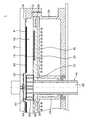
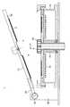
図1は、本発明の一実施例による化学気相蒸着装置の一部を切開して図示した概略断面図で、図2は、本発明の一実施例による化学気相蒸着装置の反応チャンバ内において反応が起きた後、反応チャンバのカバーを開いた状態を図示した概略断面図である。 FIG. 1 is a schematic cross-sectional view of a chemical vapor deposition apparatus according to an embodiment of the present invention, which is partially cut away. FIG. FIG. 3 is a schematic cross-sectional view illustrating a state in which a reaction chamber cover is opened after a reaction occurs in FIG.
図1及び図2を参照すると、本発明の一実施例による化学気相蒸着装置1は、基板の天井部50及び排気部60を含んで構成される。 1 and 2, a chemical
また、本発明の他の一実施例による化学気相蒸着装置1は、上記基板の天井部50が連結される反応チャンバのカバー16をさらに含むことができる。 The chemical
先ず、基板の天井部50は、反応ガスが供給され基板14がエピ成長されるようにする反応チャンバ10を形成する。 First, the
上記反応チャンバ10は、反応ガスが流動し化学反応を通して基板14に対する薄膜成長が生じる空間である。上記反応チャンバ10は、上記基板14の上部に形成される空間を基板の天井部50が覆って形成される。 The
上記反応チャンバのカバー16は、サセプタ20を収容するフレーム25を覆うように形成される。 The
上記反応チャンバのカバー16は、上記フレーム25の外部に配置される反応チャンバのカバー支持フレーム80とカバー連結部84により連結される。そして、上記反応チャンバのカバー16は、反応チャンバのカバー支持フレーム80に形成されるヒンジ部82により回転しながらフレーム25を覆う。 The
上記反応チャンバのカバー16と連結される基板の天井部50は、上記反応チャンバのカバー16の回転によりフレーム25に突出形成される基板の天井部の安着部18に置かれ、基板14上部に形成される空間を覆って反応チャンバ10を形成する。 The
上記サセプタ20の底部には、サセプタ20に収容される基板14に熱を供給する加熱部40が具備される。上記加熱部40は誘導コイルで形成され、電気抵抗により発生する熱をサセプタ20上の基板14に提供する。 A
上記加熱部40は回転軸70まで延長されたものではないため、排気部60が配置される反応チャンバ10の中心部は温度が相対的に低い。 Since the
一方、上記反応チャンバ10は、基板14がエピ成長をするようにする反応 ガスを供給するガス注入部12と連通される。そして、上記基板14は、サセプタ20に収容され、反応チャンバ10の底面から露出される。 On the other hand, the
上記サセプタ20は円形のディスクで、上記サセプタ20には上記基板14が収容される基板の収容溝24が形成される。上記サセプタ20には多数の基板14が収容され、回転軸70を中心に上記基板14が対応するように収容されることができる。 The
上記回転軸70は円筒で、上記排気部60がない場合、円筒の内部が反応後に排気ガスが排出される排気路となることができる。 When the
上記排気部60は、上記反応チャンバ10の中心部に具備され、ガス注入部12により上記反応チャンバ10に噴射される反応ガスが反応後に外部に排出されるようにする。 The
上記基板14でエピ成長反応が起こると、気相反応によるパーティクルが多く生成される。この時生成されるパーティクルは、基板の天井部50と排気部60に付着される。 When an epi growth reaction occurs on the
上記排気部60には、上記基板がエピ成長する時に発生するパーティクルが付着されるパーティクル形成部63が具備される。 The
上記基板の天井部50は、反応チャンバ10全体にわたって形成され、排気部60のパーティクル形成部63の上部に対応する部分が折れ曲がり排気部の天井部52を形成する。 The
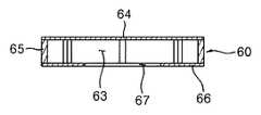
図3は、本発明の一実施例による排気部の概略斜視図で、図4は図3のA−A'線を切開した断面図である。 3 is a schematic perspective view of an exhaust unit according to an embodiment of the present invention, and FIG. 4 is a cross-sectional view taken along line AA ′ of FIG.
本実施例の排気部60は、生成されたパーティクルが付着されるパーティクル形成部63と、内部に排気路62が形成される円筒型の胴体部61に区分される。 The
上記パーティクル形成部63は、上部プレート64と下部プレート66に分かれ、上記上部プレート64と下部プレート66は、連結ロッド65で連結されて空間を形成し、その空間を通して反応後のガスが排出される。 The
上記下部プレート66は、排気ガスが排出される排気路62が形成される胴体部61と連通される。 The
即ち、上記排気部60は、サセプタ20の一側に形成される排気部の安着部22に挿入されて支持され、上記サセプタ20から脱着することができる。 That is, the
図5は、本発明の他の一実施例による排気部の概略断面図である。 FIG. 5 is a schematic cross-sectional view of an exhaust part according to another embodiment of the present invention.
図5を参照すると、本実施例の排気部60は、パーティクルが生成されるパーティクル形成部63のみから成る。 Referring to FIG. 5, the
上記パーティクル形成部63は、上部プレート64と下部プレート66に分かれ、上記上部プレート64と下部プレート66は、反応後、その間にガスが排出されるようにする空間を形成するように連結ロッド65で連結される。 The
上記下部プレート66には、排気ガスが排出される排気溝67が形成されることができる。 The
本実施例の排気部60も、サセプタ20の一側に形成される排気部の安着部22に挿入されて支持され、上記サセプタ20から脱着することができる。 The
本発明による排気部60では、サセプタ20に比べて温度が低いため、排気部60において生成されるパーティクルが容易に落ちるようになる。本発明による排気部60は、排気部の安着部22により支持され、反応チャンバのカバー16が開くときに一緒に開かないため、パーティクルが落ちないようになる。 In the
上記反応チャンバのカバー16が開いた後、排気部60を別途で取り出して排気部60に形成されるパーティクルを清掃するため、排気部60のパーティクルはきれいに除去されることができる。 After the
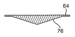
図6aから図6cは、本発明の排気部の上部プレートの様々な実施例の概略断面図である。 Figures 6a to 6c are schematic cross-sectional views of various embodiments of the exhaust top plate of the present invention.
図6aから図6cを参照すると、本発明の排気部60のパーティクル形成部63の上部プレート64の底面にパーティクルが付着される断面積を広げるための、上部プレート64の多様な実施例が開示される。 Referring to FIGS. 6a to 6c, various embodiments of the
図6aの上部プレート64は、その底面に別途のカバー部材72が具備された様子で、図6bの上部プレート64は、円錐形状に折れ曲がった折曲部74を形成したもので、図6cは、上部プレート64を中心と外郭の厚さを異なるようにして円錐形状の円錐部76を形成したものである。 The
このような形状は、上部プレート64に付着されるパーティクルの量を増やす効果がある。 Such a shape has an effect of increasing the amount of particles attached to the
本発明による化学気相蒸着装置によると、温度が相対的に低い排気部上にチャンバのカバーの開閉時に同時に開閉される基板の天井部と、別途の排気部の天井部が具備されるため、チャンバのカバーの開閉にも振動が発生せず、排気部において発生したパーティクルが基板やサセプタに落下しないという効果がある。 According to the chemical vapor deposition apparatus according to the present invention, on the exhaust portion having a relatively low temperature, the ceiling portion of the substrate that is simultaneously opened and closed when the chamber cover is opened and closed, and the ceiling portion of the separate exhaust portion are provided. There is no vibration in opening and closing the cover of the chamber, and there is an effect that particles generated in the exhaust section do not fall on the substrate or the susceptor.
また、排気部の天井部のみを別途に分離して清掃をするため、清掃時間が短縮され、装備稼働率が向上するという効果がある。 Moreover, since only the ceiling part of the exhaust part is separately separated and cleaned, the cleaning time is shortened and the equipment operating rate is improved.
10 反応チャンバ
20 サセプタ
24 基板の収容溝
40 加熱部
50 基板の天井部
52 排気部の天井部
60 排気部
62 排気路DESCRIPTION OF
Claims (10)
Translated fromJapanese前記基板の天井部と分離され、エピ成長反応後の排気ガスが排出される排気部とを含み、
前記排気部は、前記基板がエピ成長する場合に発生するパーティクルが付着されるパーティクル形成部が具備される化学気相蒸着装置。A substrate ceiling that forms a reaction chamber that is supplied with a reaction gas and allows the substrate to be epi-grown;
An exhaust part that is separated from a ceiling part of the substrate and exhaust gas after the epi-growth reaction is exhausted;
The exhaust unit is a chemical vapor deposition apparatus including a particle forming unit to which particles generated when the substrate is epitaxially grown are attached.
前記上部プレートと下部プレートは、連結ロッドで連結されて空間を形成し、その空間を通して反応後のガスが排出され、
前記下部プレートには排気溝が形成されることを特徴とする請求項1または2に記載の化学気相蒸着装置。The particle forming part is divided into an upper plate and a lower plate,
The upper plate and the lower plate are connected by a connecting rod to form a space, and the gas after reaction is discharged through the space,
The chemical vapor deposition apparatus of claim 1 or 2, wherein an exhaust groove is formed in the lower plate.
前記上部プレートと下部プレートは、連結ロッドで連結されて空間を形成し、その空間を通して反応後のガスが排出され、
前記下部プレートは、排気ガスが排出される排気路が形成される胴体部と連通されることを特徴とする請求項1または2に記載の化学気相蒸着装置。The particle forming part is divided into an upper plate and a lower plate,
The upper plate and the lower plate are connected by a connecting rod to form a space, and the gas after reaction is discharged through the space,
3. The chemical vapor deposition apparatus according to claim 1, wherein the lower plate communicates with a body portion in which an exhaust path through which exhaust gas is discharged is formed.
前記反応チャンバのカバーと連結され、基板の上部から発生されるパーティクルが付着される基板の天井部と、
前記基板の天井部と分離され、エピ成長反応後の排気ガスが排出される排気部とを含み、
前記排気部は、前記基板がエピ成長する時に発生するパーティクルが付着されるパーティクル形成部が具備される化学気相蒸着装置。A reaction chamber cover covering the reaction chamber so that the reaction gas is supplied and the substrate is epitaxially grown;
A ceiling part of the substrate connected to the cover of the reaction chamber to which particles generated from the upper part of the substrate are attached;
An exhaust part that is separated from a ceiling part of the substrate and exhaust gas after the epi-growth reaction is exhausted;
The evacuation unit is a chemical vapor deposition apparatus including a particle forming unit to which particles generated when the substrate is epitaxially grown are attached.
Applications Claiming Priority (2)
| Application Number | Priority Date | Filing Date | Title |
|---|---|---|---|
| KR1020090002398AKR101046119B1 (en) | 2009-01-12 | 2009-01-12 | Chemical vapor deposition apparatus |
| KR10-2009-0002398 | 2009-01-12 |
Publications (2)
| Publication Number | Publication Date |
|---|---|
| JP2010161340Atrue JP2010161340A (en) | 2010-07-22 |
| JP4996664B2 JP4996664B2 (en) | 2012-08-08 |
Family
ID=42318123
Family Applications (1)
| Application Number | Title | Priority Date | Filing Date |
|---|---|---|---|
| JP2009239793AExpired - Fee RelatedJP4996664B2 (en) | 2009-01-12 | 2009-10-16 | Chemical vapor deposition equipment |
Country Status (3)
| Country | Link |
|---|---|
| US (1) | US20100175620A1 (en) |
| JP (1) | JP4996664B2 (en) |
| KR (1) | KR101046119B1 (en) |
Cited By (1)
| Publication number | Priority date | Publication date | Assignee | Title |
|---|---|---|---|---|
| JP7666234B2 (en) | 2021-08-27 | 2025-04-22 | 東京エレクトロン株式会社 | Apparatus for performing film formation process on substrate and method for exhausting process gas from the apparatus for performing film formation process on substrate |
Families Citing this family (6)
| Publication number | Priority date | Publication date | Assignee | Title |
|---|---|---|---|---|
| TW201239129A (en) | 2010-12-20 | 2012-10-01 | Samsung Led Co Ltd | Chemical vapor deposition apparatus and method of manufacturing LED using the same |
| WO2012139006A2 (en)* | 2011-04-07 | 2012-10-11 | Veeco Instruments Inc. | Metal-organic vapor phase epitaxy system and process |
| WO2013022127A1 (en)* | 2011-08-09 | 2013-02-14 | 삼성전자주식회사 | Mocvd apparatus |
| US8826857B2 (en)* | 2011-11-21 | 2014-09-09 | Lam Research Corporation | Plasma processing assemblies including hinge assemblies |
| WO2013147377A1 (en)* | 2012-03-30 | 2013-10-03 | 주식회사 테스 | Vapor deposition apparatus |
| CN114892265A (en)* | 2022-04-13 | 2022-08-12 | 中国电子科技集团公司第四十八研究所 | Epitaxial growth reaction device |
Citations (4)
| Publication number | Priority date | Publication date | Assignee | Title |
|---|---|---|---|---|
| JPS63134664A (en)* | 1986-11-26 | 1988-06-07 | Hitachi Electronics Eng Co Ltd | Forming device for cvd thin film |
| JPH11135296A (en)* | 1997-07-14 | 1999-05-21 | Applied Materials Inc | Vacuum processing chamber with multi-mode access |
| JP2004063783A (en)* | 2002-07-29 | 2004-02-26 | Nanoteco Corp | Cvd equipment, substrate for semiconductor crystal growth, and method of manufacturing semiconductor device |
| JP2005045170A (en)* | 2003-07-25 | 2005-02-17 | Tokyo Electron Ltd | Gas reactor |
Family Cites Families (3)
| Publication number | Priority date | Publication date | Assignee | Title |
|---|---|---|---|---|
| US6095083A (en)* | 1991-06-27 | 2000-08-01 | Applied Materiels, Inc. | Vacuum processing chamber having multi-mode access |
| KR100703214B1 (en)* | 2006-01-02 | 2007-04-09 | 삼성전기주식회사 | Planetary Chemical Vapor Deposition Equipment |
| US20070215036A1 (en)* | 2006-03-15 | 2007-09-20 | Hyung-Sang Park | Method and apparatus of time and space co-divided atomic layer deposition |
- 2009
- 2009-01-12KRKR1020090002398Apatent/KR101046119B1/ennot_activeExpired - Fee Related
- 2009-10-15USUS12/580,145patent/US20100175620A1/ennot_activeAbandoned
- 2009-10-16JPJP2009239793Apatent/JP4996664B2/ennot_activeExpired - Fee Related
Patent Citations (4)
| Publication number | Priority date | Publication date | Assignee | Title |
|---|---|---|---|---|
| JPS63134664A (en)* | 1986-11-26 | 1988-06-07 | Hitachi Electronics Eng Co Ltd | Forming device for cvd thin film |
| JPH11135296A (en)* | 1997-07-14 | 1999-05-21 | Applied Materials Inc | Vacuum processing chamber with multi-mode access |
| JP2004063783A (en)* | 2002-07-29 | 2004-02-26 | Nanoteco Corp | Cvd equipment, substrate for semiconductor crystal growth, and method of manufacturing semiconductor device |
| JP2005045170A (en)* | 2003-07-25 | 2005-02-17 | Tokyo Electron Ltd | Gas reactor |
Cited By (1)
| Publication number | Priority date | Publication date | Assignee | Title |
|---|---|---|---|---|
| JP7666234B2 (en) | 2021-08-27 | 2025-04-22 | 東京エレクトロン株式会社 | Apparatus for performing film formation process on substrate and method for exhausting process gas from the apparatus for performing film formation process on substrate |
Also Published As
| Publication number | Publication date |
|---|---|
| KR20100083041A (en) | 2010-07-21 |
| KR101046119B1 (en) | 2011-07-01 |
| JP4996664B2 (en) | 2012-08-08 |
| US20100175620A1 (en) | 2010-07-15 |
Similar Documents
| Publication | Publication Date | Title |
|---|---|---|
| JP4996664B2 (en) | Chemical vapor deposition equipment | |
| JP5873491B2 (en) | Exhaust system for CVD reactor | |
| JP6226648B2 (en) | Method for manufacturing SiC epitaxial wafer | |
| CN107548515B (en) | Disposal Kits Including Flow Isolation Rings | |
| US6613587B1 (en) | Method of replacing at least a portion of a semiconductor substrate deposition chamber liner | |
| JP2011192661A5 (en) | Mounting table structure and film forming apparatus | |
| JP2009164162A (en) | Vapor phase growth apparatus and single crystal thin film growth method | |
| KR20140085448A (en) | Coated crucible and method of making a coated crucible | |
| KR100804358B1 (en) | Crystal layer deposition method | |
| JP2013069818A (en) | Vapor phase growth apparatus and method for forming crystal film | |
| CN219886230U (en) | Substrate processing device | |
| JP5493062B2 (en) | Metalorganic vapor phase epitaxy system | |
| JP2015527490A (en) | Manufacturing equipment for depositing material, receptacle for use therein, method for producing receptacle and method for depositing material on carrier | |
| TW201319306A (en) | Cleaning device and cleaning method for components of a vapor deposition device | |
| JP2013006739A (en) | Method for producing single crystal | |
| JP4554407B2 (en) | Growth chamber structure of vapor phase growth equipment | |
| JP2021195580A (en) | Film deposition apparatus and film deposition method | |
| CN112663059A (en) | Metal member for processing chamber and method for forming layer of metal member for processing chamber | |
| JP5401230B2 (en) | Film forming apparatus and film forming method | |
| KR102116275B1 (en) | Shielding unit, device treating substrate, and method for treating substrate using the sames | |
| JP2005057079A (en) | Manufacturing apparatus of silicon epitaxial wafer | |
| JPH0885872A (en) | Film forming equipment | |
| JP2007258516A (en) | Vapor growth equipment | |
| KR101374300B1 (en) | Exhaust member, apparatus and method for processing substrate | |
| JP2022095138A (en) | Suceptor, substrate processing equipment and substrate processing method |
Legal Events
| Date | Code | Title | Description |
|---|---|---|---|
| A977 | Report on retrieval | Free format text:JAPANESE INTERMEDIATE CODE: A971007 Effective date:20110812 | |
| A131 | Notification of reasons for refusal | Free format text:JAPANESE INTERMEDIATE CODE: A131 Effective date:20110830 | |
| A521 | Request for written amendment filed | Free format text:JAPANESE INTERMEDIATE CODE: A523 Effective date:20111130 | |
| A131 | Notification of reasons for refusal | Free format text:JAPANESE INTERMEDIATE CODE: A131 Effective date:20111226 | |
| A521 | Request for written amendment filed | Free format text:JAPANESE INTERMEDIATE CODE: A523 Effective date:20120326 | |
| TRDD | Decision of grant or rejection written | ||
| A01 | Written decision to grant a patent or to grant a registration (utility model) | Free format text:JAPANESE INTERMEDIATE CODE: A01 Effective date:20120417 | |
| A01 | Written decision to grant a patent or to grant a registration (utility model) | Free format text:JAPANESE INTERMEDIATE CODE: A01 | |
| A61 | First payment of annual fees (during grant procedure) | Free format text:JAPANESE INTERMEDIATE CODE: A61 Effective date:20120511 | |
| FPAY | Renewal fee payment (event date is renewal date of database) | Free format text:PAYMENT UNTIL: 20150518 Year of fee payment:3 | |
| R150 | Certificate of patent or registration of utility model | Free format text:JAPANESE INTERMEDIATE CODE: R150 | |
| FPAY | Renewal fee payment (event date is renewal date of database) | Free format text:PAYMENT UNTIL: 20150518 Year of fee payment:3 | |
| S111 | Request for change of ownership or part of ownership | Free format text:JAPANESE INTERMEDIATE CODE: R313111 | |
| S631 | Written request for registration of reclamation of domicile | Free format text:JAPANESE INTERMEDIATE CODE: R313631 | |
| FPAY | Renewal fee payment (event date is renewal date of database) | Free format text:PAYMENT UNTIL: 20150518 Year of fee payment:3 | |
| R371 | Transfer withdrawn | Free format text:JAPANESE INTERMEDIATE CODE: R371 | |
| S111 | Request for change of ownership or part of ownership | Free format text:JAPANESE INTERMEDIATE CODE: R313111 | |
| S631 | Written request for registration of reclamation of domicile | Free format text:JAPANESE INTERMEDIATE CODE: R313631 | |
| S633 | Written request for registration of reclamation of name | Free format text:JAPANESE INTERMEDIATE CODE: R313633 | |
| FPAY | Renewal fee payment (event date is renewal date of database) | Free format text:PAYMENT UNTIL: 20150518 Year of fee payment:3 | |
| R371 | Transfer withdrawn | Free format text:JAPANESE INTERMEDIATE CODE: R371 | |
| FPAY | Renewal fee payment (event date is renewal date of database) | Free format text:PAYMENT UNTIL: 20150518 Year of fee payment:3 | |
| S111 | Request for change of ownership or part of ownership | Free format text:JAPANESE INTERMEDIATE CODE: R313111 | |
| S531 | Written request for registration of change of domicile | Free format text:JAPANESE INTERMEDIATE CODE: R313531 | |
| S533 | Written request for registration of change of name | Free format text:JAPANESE INTERMEDIATE CODE: R313533 | |
| FPAY | Renewal fee payment (event date is renewal date of database) | Free format text:PAYMENT UNTIL: 20150518 Year of fee payment:3 | |
| R350 | Written notification of registration of transfer | Free format text:JAPANESE INTERMEDIATE CODE: R350 | |
| R250 | Receipt of annual fees | Free format text:JAPANESE INTERMEDIATE CODE: R250 | |
| LAPS | Cancellation because of no payment of annual fees |