JP2010148879A - Surgical stapling apparatus - Google Patents
Surgical stapling apparatusDownload PDFInfo
- Publication number
- JP2010148879A JP2010148879AJP2009291507AJP2009291507AJP2010148879AJP 2010148879 AJP2010148879 AJP 2010148879AJP 2009291507 AJP2009291507 AJP 2009291507AJP 2009291507 AJP2009291507 AJP 2009291507AJP 2010148879 AJP2010148879 AJP 2010148879A
- Authority
- JP
- Japan
- Prior art keywords
- assembly
- knife blade
- distal
- anvil
- cartridge
- Prior art date
- Legal status (The legal status is an assumption and is not a legal conclusion. Google has not performed a legal analysis and makes no representation as to the accuracy of the status listed.)
- Granted
Links
Images


Classifications
- A—HUMAN NECESSITIES
- A61—MEDICAL OR VETERINARY SCIENCE; HYGIENE
- A61B—DIAGNOSIS; SURGERY; IDENTIFICATION
- A61B17/00—Surgical instruments, devices or methods
- A61B17/068—Surgical staplers, e.g. containing multiple staples or clamps
- A61B17/072—Surgical staplers, e.g. containing multiple staples or clamps for applying a row of staples in a single action, e.g. the staples being applied simultaneously
- A61B17/07207—Surgical staplers, e.g. containing multiple staples or clamps for applying a row of staples in a single action, e.g. the staples being applied simultaneously the staples being applied sequentially
- A—HUMAN NECESSITIES
- A61—MEDICAL OR VETERINARY SCIENCE; HYGIENE
- A61B—DIAGNOSIS; SURGERY; IDENTIFICATION
- A61B17/00—Surgical instruments, devices or methods
- A61B17/068—Surgical staplers, e.g. containing multiple staples or clamps
- A61B17/072—Surgical staplers, e.g. containing multiple staples or clamps for applying a row of staples in a single action, e.g. the staples being applied simultaneously
- A61B17/07292—Reinforcements for staple line, e.g. pledgets
- A—HUMAN NECESSITIES
- A61—MEDICAL OR VETERINARY SCIENCE; HYGIENE
- A61B—DIAGNOSIS; SURGERY; IDENTIFICATION
- A61B17/00—Surgical instruments, devices or methods
- A61B2017/0023—Surgical instruments, devices or methods disposable
- A—HUMAN NECESSITIES
- A61—MEDICAL OR VETERINARY SCIENCE; HYGIENE
- A61B—DIAGNOSIS; SURGERY; IDENTIFICATION
- A61B17/00—Surgical instruments, devices or methods
- A61B2017/0046—Surgical instruments, devices or methods with a releasable handle; with handle and operating part separable
- A61B2017/00473—Distal part, e.g. tip or head
Landscapes
- Health & Medical Sciences (AREA)
- Life Sciences & Earth Sciences (AREA)
- Surgery (AREA)
- Heart & Thoracic Surgery (AREA)
- Engineering & Computer Science (AREA)
- Biomedical Technology (AREA)
- Nuclear Medicine, Radiotherapy & Molecular Imaging (AREA)
- Medical Informatics (AREA)
- Molecular Biology (AREA)
- Animal Behavior & Ethology (AREA)
- General Health & Medical Sciences (AREA)
- Public Health (AREA)
- Veterinary Medicine (AREA)
- Surgical Instruments (AREA)
Abstract
Translated fromJapaneseDescription
Translated fromJapanese(関連出願の引用)
本願は、2008年3月5日に出願された国際(PCT)出願第PCT/US2008/002981号の一部継続出願であり、該PCT出願は、米国仮出願第60/905,566号の優先権の利益を主張し、各出願の全内容は、本願明細書中に参照により援用される。
(技術分野)
本開示は、外科用装置(例えば、外科用ステープリング装置)に関する。より詳細には、本開示は、取り外し可能な外科用支持および/または内視鏡外科用ステープリング装置を含む外科用ステープリング装置に関し、外科用ステープリング装置は、ローディングユニットのための取り外し可能な外科用支持(例えば、シングル使用ローディングユニット(「SULU」)あるいは、使い捨て可能なローディングユニット(「DLU」)を含む。簡単のために、今後は、SULUあるいはDLUは「DLU」と呼ぶが、DLUあるいはSULUのいずれかあるいは両方を含むことを理解しなければならない。(Citation of related application)
This application is a continuation-in-part of International (PCT) Application No. PCT / US2008 / 002981 filed on March 5, 2008, which is a priority of US Provisional Application No. 60 / 905,566. All rights reserved, and the entire contents of each application are incorporated herein by reference.
(Technical field)
The present disclosure relates to surgical devices (eg, surgical stapling devices). More particularly, the present disclosure relates to a surgical stapling apparatus including a removable surgical support and / or endoscopic surgical stapling apparatus, the surgical stapling apparatus being removable for a loading unit Surgical support (eg, single use loading unit (“SULU”) or disposable loading unit (“DLU”)) For simplicity, SULU or DLU will be referred to as “DLU” from now on, Or it must be understood to include either or both of the SULUs.
対向する咬合構造の間で組織が最初につかまれるあるいはクランプされ、その後外科用ファスナで縫合される外科用デバイスは、当該分野では公知である。いくつかの器具では、ファスナで縫合された組織を切るためにナイフが提供される。ファスナは、通常外科用ステープルの形をしているが、2部分の重合体のファスナが使用され得る。 Surgical devices in which tissue is first grasped or clamped between opposing occlusal structures and then sutured with a surgical fastener are known in the art. In some instruments, a knife is provided to cut the sutured tissue. The fasteners are usually in the form of surgical staples, but two-part polymeric fasteners can be used.
この目的の器具は、2つの細長い咬合部材を含み、細長い咬合部材は、捕捉するあるいはクランプするためにそれぞれ使用される。通常、咬合部材の1つは、ステープルカートリッジを運び、ステープルカートリッジは、少なくとも2つの横方向の列に整列された複数のステープルを収容し、他方の咬合部材は、ステープルがステープルカートリッジから引き出されるときに、ステープル脚を形成するための表面を画定するアンビルを有している。通常、ステープリング動作は、ステープルカートリッジを通して長手方向に動くカム部材によってもたらされ、カム部材は、ステープルプッシャ上で動作をして、連続してステープルカートリッジを取り出す。ナイフは、ステープル列の間で、ステープル組織を長手方向に切るおよび/または開く。このような器具が、例えば、特許文献1および、特許文献2に開示されている。 The instrument for this purpose includes two elongate occlusal members, each of which is used to capture or clamp. Typically, one of the occlusal members carries a staple cartridge, the staple cartridge containing a plurality of staples aligned in at least two lateral rows, and the other occlusal member is when the staples are withdrawn from the staple cartridge. And an anvil defining a surface for forming the staple legs. Typically, the stapling operation is provided by a cam member that moves longitudinally through the staple cartridge, which operates on the staple pusher to continuously remove the staple cartridge. The knife cuts and / or opens the staple tissue longitudinally between the staple rows. Such instruments are disclosed in, for example,
特許文献3に開示された最近のステープラは、切開のそれぞれの側にステープルの二重の列を適用している。この特許は、使い捨てローディングユニットを有する外科用ステープラを開示しており、使い捨てローディングユニット内では、カム部材が溝を運ぶ2組の互い違いのステープルの間の細長い誘導経路を通って動く。ステープル駆動部材は、溝の中に配置され、長手方向に動くカム部材によって接触されるような方法で配置されており、使い捨てローディングユニットのステープルカートリッジからのステープルの取り出しをもたらす。そのようなステープラの他の例が、特許文献4および特許文献5に開示されている。 A recent stapler disclosed in U.S. Patent No. 6,057,057 applies a double row of staples on each side of the incision. This patent discloses a surgical stapler having a disposable loading unit in which a cam member moves through an elongated guide path between two sets of alternating staples carrying a groove. The staple drive member is disposed in the groove and is disposed in such a manner as to be contacted by a longitudinally moving cam member, resulting in removal of the staple from the staple cartridge of the disposable loading unit. Other examples of such a stapler are disclosed in
上に記述された器具のそれぞれは、従来の外科手術での使用で区別され、外科医は動作サイトへの直接の手動アクセスを有している。しかしながら、内視鏡あるいは腹腔鏡手術では、外科手術が小さい切開を通って、あるいは、皮膚の小さい入口創傷を介して挿入された狭いカニューレを通じて実行される。内視鏡および/または腹腔鏡手術に対処するために、内視鏡外科用ステープリングデバイスが開発されて来ており、例えば、米国特許第5,040,715号(Green他)、米国特許第5,307,976号(Olson他)、米国特許第5,312,023号(Green他)、米国特許第5,318,221号(Green他)、米国特許第5,326,013号(Green他)、米国特許第5,332,142号(Robinson他)、および、米国特許第6,241,139号(Milliman他)に開示されており、それぞれの全体の内容が本明細書に参照として援用されている。 Each of the instruments described above is distinguished for use in conventional surgery, and the surgeon has direct manual access to the operating site. However, in endoscopic or laparoscopic surgery, surgery is performed through a small incision or through a narrow cannula inserted through a small entrance wound in the skin. Endoscopic surgical stapling devices have been developed to address endoscopic and / or laparoscopic surgery, for example, US Pat. No. 5,040,715 (Green et al.), US Pat. US Pat. No. 5,307,976 (Olson et al.), US Pat. No. 5,312,023 (Green et al.), US Pat. No. 5,318,221 (Green et al.), US Pat. No. 5,326,013 (Green) Et al., U.S. Pat. No. 5,332,142 (Robinson et al.), And U.S. Pat. No. 6,241,139 (Milliman et al.), The entire contents of each of which are incorporated herein by reference. Has been incorporated.
本出願の譲受人である、Tyco Healthcare Group,LPは、長年にわたり、Multifire ENDO GIATM.30およびMultifire ENDO GIATM.60装置のような内視鏡ステープリング器具を製造し販売してきた。これらの装置は外科用ステープリング装置およびDLUを含む。一般には、DLUは手術の直前に装置に取り付けられる。使用後は、DLUは装置から除去され得、新しいDLUが装置に取り付けられ、さらなるステープリングおよび/または切開手術を実行する。これらの装置は、重要な臨床医療の恩恵を提供した。それにも係らず、これらの装置に対する改良がまだ可能である。The assignee of this application, Tyco Healthcare Group, LP, has been working with Multifire ENDO GIA™ . 30 and Multifire ENDO GIA™ . Endoscopic stapling instruments such as 60 devices have been manufactured and sold. These devices include surgical stapling devices and DLUs. In general, the DLU is attached to the device just prior to surgery. After use, the DLU can be removed from the device and a new DLU is attached to the device to perform further stapling and / or open surgery. These devices provided significant clinical health benefits. Nevertheless, improvements to these devices are still possible.
外科用ステープリング装置のカートリッジの半断面の組織接触面およびアンビルの半断面のうちの少なくとも1つに選択的に接続された外科用支持を提供することが望まれる。 It would be desirable to provide a surgical support selectively connected to at least one of a half-section tissue contacting surface of a cartridge of a surgical stapling apparatus and a half-section of an anvil.
外科用ステープリング装置の動作中に、外科用支持を、カートリッジの半断面の組織接触面および/またはアンビルの半断面の組織接触面から除去するシステムを提供することが望まれる。 It would be desirable to provide a system that removes surgical support from the cartridge half-section tissue contacting surface and / or the anvil half-section tissue contacting surface during operation of the surgical stapling apparatus.
従って、上述の希望を満たすことがこの開示の目的である。 Accordingly, it is an object of this disclosure to satisfy the above-mentioned hopes.
本開示によると、ハウジング、ハウジングに支持されたハンドル、ハウジングから遠位に延びローディングユニットに解放可能に係合するように適合された遠位端を有する細長い本体、およびハウジングの遠位端に支持可能なローディングユニットを含む外科用ステープリング装置が提供されている。ローディングユニットはツールアセンブリを含み、ツールアセンブリはカートリッジアセンブリを有し、カートリッジアセンブリはステープルカートリッジを解放可能に支持するように構成され適合されており、ステープルカートリッジは複数の外科用ファスナをその中に有し、アンビルアセンブリは可動にカートリッジアセンブリに関して固定されており、アンビルアセンブリは、アンビルプレートを支持するように構成され、適合されており、アンビルアセンブリおよびステープルカートリッジのそれぞれは、細長い長手方向スロットを画定する。ローディングユニットは、解放可能にアンビルプレートおよびカートリッジアセンブリのうちの少なくとも1つの組織接触面に固定された外科用支持をさらに含み、各外科用支持は、アンビルアセンブリおよびカートリッジアセンブリのうちの少なくとも1つに、少なくとも1つのアンカーによって解放可能に固定されている。ローディングユニットは、なおも、ツールアセンブリにスライド可能に支持された駆動アセンブリをさらに含み、駆動アセンブリは、各細長い長手方向スロット内にスライド可能に配置されたナイフ刃を含み、駆動アセンブリの近位位置から遠位位置への動きは、そのナイフ刃が少なくとも1つのアンカーを切断し、各外科用支持を、少なくとも1つのアンビルアセンブリおよびカートリッジアセンブリのそれぞれから解放する。 According to the present disclosure, a housing, a handle supported on the housing, an elongated body having a distal end extending distally from the housing and adapted to releasably engage the loading unit, and supported on the distal end of the housing A surgical stapling apparatus is provided that includes a possible loading unit. The loading unit includes a tool assembly, the tool assembly having a cartridge assembly, the cartridge assembly configured and adapted to releasably support the staple cartridge, the staple cartridge having a plurality of surgical fasteners therein. And the anvil assembly is movably fixed with respect to the cartridge assembly, the anvil assembly configured and adapted to support the anvil plate, each of the anvil assembly and the staple cartridge defining an elongated longitudinal slot. . The loading unit further includes a surgical support releasably secured to at least one tissue contacting surface of the anvil plate and cartridge assembly, each surgical support being attached to at least one of the anvil assembly and cartridge assembly. , Releasably secured by at least one anchor. The loading unit still further includes a drive assembly slidably supported on the tool assembly, the drive assembly including a knife blade slidably disposed within each elongated longitudinal slot, the proximal position of the drive assembly. Movement from the distal position to the distal position causes the knife blade to cut at least one anchor, releasing each surgical support from each of the at least one anvil assembly and cartridge assembly.
アンビルアセンブリは、外科用支持をそれに固定する近位縫合糸、および/または、それに外科用支持を固定する遠位アンカーを含み得る。カートリッジアセンブリは、外科用支持をそれに固定する近位アンカー、および/または、外科用支持をそれに固定する遠位アンカーを含み得る。アンビルアセンブリおよびカートリッジアセンブリの各アンカーは、アンビルプレートおよびステープルカートリッジのそれぞれの長手方向スロットを横切って延び得る。 The anvil assembly may include a proximal suture that secures the surgical support thereto and / or a distal anchor that secures the surgical support thereto. The cartridge assembly may include a proximal anchor that secures the surgical support thereto and / or a distal anchor that secures the surgical support thereto. Each anchor of the anvil assembly and cartridge assembly may extend across a respective longitudinal slot of the anvil plate and staple cartridge.
アンビルアセンブリは、スライド可能にあるいは回転可能にその中に支持されたナイフ刃を含み得、ナイフ縁を画定する。アンビルアセンブリのナイフ刃は、その作動が起きると、アンビルアセンブリの近位および遠位アンカーのうちの少なくとも1つを切断し得る。アンビルアセンブリのナイフ刃は、アンビルアセンブリの遠位アンカーの実質的に近位に配置された第1の位置、および、アンビルアセンブリの遠位アンカーの実質的に遠位に配置された第2の位置を有し得、それによって、アンビルアセンブリの遠位アンカーを切断する。駆動アセンブリは、駆動アセンブリの遠位作動がおきるとすぐに、アンビルアセンブリのナイフ刃を第1の位置から第2の位置に動かし得る。 The anvil assembly may include a knife blade slidably or rotatably supported therein to define a knife edge. The anvil assembly knife blade may cut at least one of the proximal and distal anchors of the anvil assembly when actuation occurs. The knife blade of the anvil assembly has a first position disposed substantially proximal to the distal anchor of the anvil assembly and a second position disposed substantially distal to the distal anchor of the anvil assembly. Thereby cutting the distal anchor of the anvil assembly. The drive assembly may move the knife blade of the anvil assembly from the first position to the second position as soon as the distal actuation of the drive assembly occurs.
カートリッジアセンブリは、スライド可能にあるいは回転可能に支持され、ナイフ縁を画定するナイフ刃をその中に含み得、それが駆動されると、カートリッジアセンブリの近位および遠位アンカーのうちの少なくとも1つを切断する。カートリッジアセンブリのナイフ刃は、カートリッジアセンブリの遠位アンカーの実質的に近位に配置された第1の位置、および、カートリッジアセンブリの遠位アンカーの実質的に遠位に配置された第2の位置を有し得、それによって、カートリッジアセンブリの遠位アンカーを切断する。駆動アセンブリは、駆動アセンブリの遠位作動がおきるとすぐに、カートリッジアセンブリのナイフ刃を第1の位置から第2の位置に動かし得る。 The cartridge assembly may include a knife blade therein that is slidably or rotatably supported and defines a knife edge, and when driven, at least one of the proximal and distal anchors of the cartridge assembly. Disconnect. The knife blade of the cartridge assembly has a first position disposed substantially proximal to the distal anchor of the cartridge assembly and a second position disposed substantially distal to the distal anchor of the cartridge assembly. Thereby cutting the distal anchor of the cartridge assembly. The drive assembly may move the knife blade of the cartridge assembly from the first position to the second position as soon as distal actuation of the drive assembly occurs.
本開示の他の態様によると、外科用ステープリング装置とともに使用されるローディングユニットが提供される。ローディングユニットは、ツールアセンブリおよびアンビルアセンブリを含み、ツールアセンブリは、複数の外科用ファスナをその中に有するステープルカートリッジを解放可能に支持するように構成され適合されたカートリッジアセンブリを有しており、アンビルアセンブリは、カートリッジアセンブリに対して可動に固定されており、アンビルアセンブリはアンビルプレートを支持するように構成され適合されており、アンビルプレートおよびステープルカートリッジのそれぞれは、細長い長手方向スロットを画定する。ローディングユニットは、また、アンビルプレートおよびステープルカートリッジのうちの少なくとも1つに組織接触面に解放可能に固定された外科用支持を含み、各外科用支持は、アンビルアセンブリおよびカートリッジアセンブリのうちの少なくとも1つに、少なくとも1つのアンカーによって固定されている。ローディングユニットは、ツールアセンブリの中にスライド可能に支持された駆動アセンブリを含み、駆動アセンブリは、各細長い長手方向スロット内にスライド可能に配置されたナイフ刃を含んでおり、駆動アセンブリの近位位置から遠位位置への動きは、そのナイフ刃が少なくとも1つのアンカーを切断し、各外科用支持を、アンビルアセンブリおよびカートリッジアセンブリのうちの少なくとも1つのそれぞれから解放する結果をもたらす。 According to another aspect of the present disclosure, a loading unit for use with a surgical stapling apparatus is provided. The loading unit includes a tool assembly and an anvil assembly, the tool assembly having a cartridge assembly configured and adapted to releasably support a staple cartridge having a plurality of surgical fasteners therein, the anvil The assembly is movably fixed relative to the cartridge assembly, and the anvil assembly is configured and adapted to support the anvil plate, each of the anvil plate and staple cartridge defining an elongated longitudinal slot. The loading unit also includes a surgical support releasably secured to the tissue contacting surface to at least one of the anvil plate and the staple cartridge, each surgical support including at least one of the anvil assembly and the cartridge assembly. One is fixed by at least one anchor. The loading unit includes a drive assembly slidably supported within the tool assembly, the drive assembly including a knife blade slidably disposed within each elongated longitudinal slot, the proximal position of the drive assembly. Movement from the distal position to the distal position results in the knife blade cutting at least one anchor and releasing each surgical support from each of at least one of the anvil assembly and the cartridge assembly.
本開示のなおも他の態様によると、外科用ステープリング装置と選択的に使用のためのローディングユニットが提供される。ローディングユニットは、ツールアセンブリおよびアンビルアセンブリを含み、ツールアセンブリは、複数の外科用ファスナをその中に有するステープルカートリッジを解放可能に支持するように構成され適合されたカートリッジアセンブリを有しており、アンビルアセンブリは、カートリッジアセンブリに対して可動に固定されており、アンビルアセンブリはアンビルプレートを支持するように構成され適合されており、アンビルプレートおよびステープルカートリッジのそれぞれは、細長い長手方向スロットを画定する。ローディングユニットは、外科用支持およびアンカーをさらに含み、外科用支持は、アンビルプレートおよびステープルカートリッジのそれぞれの組織接触面に解放可能に固定されており、アンカーは、外科用支持をアンビルプレートおよびステープルカートリッジのそれぞれに固定しており、アンカーは、アンビルアセンブリおよびカートリッジアセンブリのそれぞれの近位端および遠位端の近くに配置されている。ローディングユニットは、また、アンビルアセンブリに動作可能なように配置されたナイフ刃を含み、アンビルアセンブリのナイフ刃は、アンビルアセンブリの遠位アンカーの近位に配置された第1の位置、および、アンビルアセンブリの遠位アンカーの実質的に遠位に配置された第2の位置を有し、それによって、アンビルアセンブリの遠位アンカーを切断する。ローディングユニットは、カートリッジアセンブリに動作可能なように配置されたナイフ刃をなおもさらに含み、カートリッジアセンブリのナイフ刃は、カートリッジアセンブリの遠位アンカーの近位に配置された第1の位置、および、カートリッジアセンブリの遠位アンカーの遠位に配置された第2の位置を有し、それによって、カートリッジアセンブリの遠位アンカーを切断する。ローディングユニットは、また、ツールアセンブリの中にスライド可能に支持された駆動アセンブリを含み、駆動アセンブリは各細長い長手方向スロット内にスライド可能に配置されたナイフ刃を含んでおり、駆動アセンブリの近位位置から遠位位置への動きは、そのナイフ刃がアンビルアセンブリおよびカートリッジアセンブリのそれぞれの近位アンカーを切断し、各外科用支持の近位端を、アンビルアセンブリおよびカートリッジアセンブリのうちの少なくとも1つのそれぞれから解放する結果をもたらし、駆動アセンブリの近位位置から遠位位置への動きは、アンビルアセンブリのナイフ刃およびカートリッジアセンブリのナイフ刃を、それらのそれぞれの第1の位置からそれらのそれぞれの第2の位置に動かし、それによって、アンビルアセンブリおよびカートリッジアセンブリのそれぞれの遠位アンカーを切断し、各外科用支持の遠位端を、少なくとも1つのアンビルアセンブリおよびカートリッジアセンブリのそれぞれから解放する。 According to still other aspects of the present disclosure, a surgical stapling apparatus and a loading unit for selective use are provided. The loading unit includes a tool assembly and an anvil assembly, the tool assembly having a cartridge assembly configured and adapted to releasably support a staple cartridge having a plurality of surgical fasteners therein, the anvil The assembly is movably fixed relative to the cartridge assembly, and the anvil assembly is configured and adapted to support the anvil plate, each of the anvil plate and staple cartridge defining an elongated longitudinal slot. The loading unit further includes a surgical support and an anchor, the surgical support being releasably secured to the respective tissue contacting surfaces of the anvil plate and the staple cartridge, and the anchor provides the surgical support to the anvil plate and the staple cartridge. And anchors are disposed near the proximal and distal ends of the anvil assembly and cartridge assembly, respectively. The loading unit also includes a knife blade operably disposed on the anvil assembly, the knife blade of the anvil assembly having a first position disposed proximal to the distal anchor of the anvil assembly, and the anvil. Having a second position disposed substantially distal to the distal anchor of the assembly, thereby cutting the distal anchor of the anvil assembly. The loading unit still further includes a knife blade operably disposed on the cartridge assembly, the knife blade of the cartridge assembly having a first position disposed proximal to the distal anchor of the cartridge assembly; and The second position is located distal to the distal anchor of the cartridge assembly, thereby cutting the distal anchor of the cartridge assembly. The loading unit also includes a drive assembly slidably supported within the tool assembly, the drive assembly including a knife blade slidably disposed within each elongated longitudinal slot, proximal of the drive assembly. The movement from the position to the distal position is such that the knife blade cuts the proximal anchor of each of the anvil assembly and cartridge assembly, and the proximal end of each surgical support is moved to at least one of the anvil assembly and cartridge assembly. The result of releasing from each is that the movement of the drive assembly from the proximal position to the distal position causes the knife blade of the anvil assembly and the knife blade of the cartridge assembly to move from their respective first positions to their respective first positions. Move it to
本開示のさらなる態様によると、外科用ステープリング装置が提供される。外科用ステープリング装置は、組織接触面を画定するカートリッジアセンブリ、組織接触面を画定するアンビルアセンブリ、および、カートリッジアセンブリの組織接触面およびアンビルアセンブリの組織接触面のうちの少なくとも1つに、少なくとも1つのアンカーによって解放可能に固定された外科用支持を含む。 According to a further aspect of the present disclosure, a surgical stapling apparatus is provided. The surgical stapling apparatus includes at least one of a cartridge assembly defining a tissue contacting surface, an anvil assembly defining a tissue contacting surface, and at least one of the tissue contacting surface of the cartridge assembly and the tissue contacting surface of the anvil assembly. Including surgical support releasably secured by one anchor.
アンカーは、各外科用支持の近位端および遠位端のうちの少なくとも1つの近くに配置され得る。各アンカーは、カートリッジアセンブリおよびアンビルアセンブリのそれぞれのうちの1つの長手方向軸を横断して延び得る。 An anchor may be disposed near at least one of the proximal and distal ends of each surgical support. Each anchor may extend across the longitudinal axis of one of each of the cartridge assembly and the anvil assembly.
アンカーは、縫合糸、糸、テザー、ストラップ、バンド、線、ワイヤ、ケーブル、タック、アンカーおよびファスナからなる群から選択され得る。 The anchor may be selected from the group consisting of sutures, threads, tethers, straps, bands, wires, wires, cables, tacks, anchors and fasteners.
少なくとも近位アンカーは、カートリッジアセンブリおよびアンビルアセンブリのそれぞれに形成された、それぞれの長手方向ナイフスロットを横切って延び得、および/または、少なくとも遠位アンカーは、カートリッジアセンブリおよびアンビルアセンブリのそれぞれに形成されたそれぞれの長手方向ナイフスロットを横切って延び得る。 At least the proximal anchor may extend across a respective longitudinal knife slot formed in each of the cartridge assembly and the anvil assembly, and / or at least a distal anchor is formed in each of the cartridge assembly and the anvil assembly. And can extend across each longitudinal knife slot.
アンカーは、外科用ステープリング装置が作動するとすぐに、それぞれの外科用支持を解放し得る。各アンカーは、外科用ステープリング装置が作動するとすぐに、外科用支持を解放するように切断され得る。 The anchors can release their respective surgical supports as soon as the surgical stapling device is activated. Each anchor can be cut to release surgical support as soon as the surgical stapling device is activated.
外科用ステープリング装置は、カートリッジアセンブリおよびアンビルアセンブリのそれぞれに形成されたそれぞれの長手方向ナイフスロットを通って、スライド可能な往復運動をするように構成され、大きさが決められており、ナイフ刃が、その遠位への前進が起きるとすぐに、アンカーを切断する。 The surgical stapling apparatus is configured and sized for slidable reciprocation through respective longitudinal knife slots formed in each of the cartridge assembly and the anvil assembly. However, as soon as its distal advancement occurs, the anchor is cut.
外科用ステープリング装置は、カートリッジアセンブリおよびアンビルアセンブリに沿った軸方向変位のためにスライド可能に支持された駆動アセンブリをさらに含み得、駆動アセンブリの近位位置から遠位位置への駆動アセンブリの動きは、カートリッジアセンブリおよびアンビルアセンブリのうちのそれぞれの1つからの外科用支持の分離をもたらす。 The surgical stapling apparatus may further include a drive assembly slidably supported for axial displacement along the cartridge assembly and the anvil assembly, wherein the drive assembly moves from a proximal position to a distal position of the drive assembly. Provides separation of the surgical support from each one of the cartridge assembly and the anvil assembly.
アンカーは、各外科用支持の近位端および遠位端のうちの少なくとも1つの近くに配置され得る。駆動アセンブリは、カートリッジアセンブリおよびアンビルアセンブリのそれぞれから外科用支持を解放するために、各アンカーを直接切断し得るか、あるいは、各アンカーが切断されることを起こし得る。 An anchor may be disposed near at least one of the proximal and distal ends of each surgical support. The drive assembly can cut each anchor directly or cause each anchor to be cut to release surgical support from each of the cartridge assembly and the anvil assembly.
本開示のさらなる実施形態によると、外科用ステープリング装置が提供され、外科用ステープリング装置は、組織接触面および長手方向に延びる細長いスロットを画定するカートリッジアセンブリ、組織接触面および長手方向に延びる細長いスロットを画定するアンビルアセンブリ、およびカートリッジアセンブリの組織接触面およびアンビルアセンブリの組織接触面のうちの少なくとも1つに、少なくとも1つのアンカーによって解放可能に固定された外科用支持を含み、各支持は、その近位縁に形成され、カートリッジアセンブリおよびアンビルアセンブリのそれぞれの長手方向に延びる細長いスロットに実質的に整列されたノッチを画定する。 According to further embodiments of the present disclosure, a surgical stapling apparatus is provided, the surgical stapling apparatus comprising a cartridge assembly defining a tissue contacting surface and a longitudinally extending elongated slot, a tissue contacting surface and a longitudinally extending elongated. An anvil assembly defining a slot, and a surgical support releasably secured to at least one of the tissue contacting surface of the cartridge assembly and the tissue contacting surface of the anvil assembly by at least one anchor, each support comprising: A notch is formed at its proximal edge and substantially aligned with an elongated slot extending in the longitudinal direction of each of the cartridge assembly and the anvil assembly.
外科用ステープリング装置は、カートリッジアセンブリおよびアンビルアセンブリの、長手方向に延びる細長いスロットにおける、スライド可能な使い捨て可能な中央ナイフ刃をさらに含み得、中央ナイフ刃は、長手方向に延びる細長いスロットを通って中央ナイフ刃の前進が起きるとすぐに、各外科用支持のノッチの中に受容される。 The surgical stapling apparatus may further include a slidable disposable central knife blade in a longitudinally extending elongated slot of the cartridge assembly and anvil assembly, the central knife blade passing through the longitudinally extending elongated slot. As soon as the advancement of the central knife blade occurs, it is received in each surgical support notch.
カートリッジアセンブリおよびアンビルアセンブリのそれぞれは、そのそれぞれの側縁に形成された制限スロットの遠位対、およびそのそれぞれの側縁に形成された制限スロットの近位対を含み得る。縫合糸は、それにそれぞれの外科用支持を固定するために、カートリッジアセンブリおよびアンビルアセンブリの制限スロットのそれぞれの近位対および遠位対を横切って延び得る。 Each of the cartridge assembly and the anvil assembly may include a distal pair of restriction slots formed on its respective side edges and a proximal pair of restriction slots formed on its respective side edges. Sutures may extend across respective proximal and distal pairs of restriction slots of the cartridge assembly and anvil assembly to secure the respective surgical support thereto.
各外科用支持は、各制限スロットに登録のその側縁に形成されたノッチを含み得る。 Each surgical support may include a notch formed in its side edge of registration in each restriction slot.
外科用ステープリング装置は、カートリッジアセンブリおよびアンビルアセンブリのうちの少なくとも1つの遠位端部分に支持されたナイフ刃をさらに含み得る。遠位ナイフ刃は、中央ナイフ刃が作動するとすぐに、中央ナイフ刃によって作動可能であり得る。 The surgical stapling apparatus may further include a knife blade supported on the distal end portion of at least one of the cartridge assembly and the anvil assembly. The distal knife blade may be actuable by the central knife blade as soon as the central knife blade is activated.
外科用ステープリング装置は、カートリッジアセンブリおよびアンビルアセンブリのうちの少なくとも1つの遠位端部分に支持されたナイフ刃をなおもさらに含み得、中央ナイフ刃が駆動バーの上に支持され、遠位ナイフ刃は、駆動バーが作動するとすぐに、中央ナイフ刃および駆動バーのうちの少なくとも1つによって、作動可能である。 The surgical stapling apparatus may still further include a knife blade supported on the distal end portion of at least one of the cartridge assembly and the anvil assembly, the central knife blade supported on the drive bar, The blade is operable by at least one of the central knife blade and the drive bar as soon as the drive bar is activated.
本開示のなおも他の実施形態によると、外科用ステープリング装置が提供され、組織接触面を画定するカートリッジアセンブリ、および組織接触面を画定するアンビルアセンブリを含み、カートリッジアセンブリおよびアンビルアセンブリのうちの少なくとも1つの組織接触面が、その上に形成されたグリップ増強機構、およびカートリッジアセンブリの組織接触面およびアンビルアセンブリの組織接触面うちの少なくとも1つに、少なくとも1つのアンカーによって解放可能に固定された外科用支持を含み、カートリッジアセンブリおよびアンビルアセンブリのそれぞれに関する該外科用支持の位置が、グリップ増強機構を欠いているカートリッジアセンブリおよびアンビルアセンブリに比較してより良く維持されている。 According to still other embodiments of the present disclosure, a surgical stapling apparatus is provided, including a cartridge assembly that defines a tissue contacting surface, and an anvil assembly that defines a tissue contacting surface, of the cartridge assembly and the anvil assembly. At least one tissue contacting surface is releasably secured to at least one of the grip augmenting mechanism formed thereon and the tissue contacting surface of the cartridge assembly and the tissue contacting surface of the anvil assembly by at least one anchor. The position of the surgical support with respect to each of the cartridge assembly and the anvil assembly, including the surgical support, is better maintained as compared to the cartridge assembly and the anvil assembly lacking the grip augmentation mechanism.
カートリッジアセンブリおよびアンビルアセンブリのうちの少なくとも1つの組織接触面は、遠位グリップ増強機構および近位グリップ増強機構のうちの少なくとも1つを含み得る。 At least one tissue contacting surface of the cartridge assembly and the anvil assembly may include at least one of a distal grip augmentation mechanism and a proximal grip augmentation mechanism.
カートリッジアセンブリおよびアンビルアセンブリのそれぞれは、長手方向に延びている細長いスロットを画定し、カートリッジアセンブリおよび該アンビルアセンブリのうちの少なくとも1つの組織接触面は、長手方向に延びている細長いスロットの遠位に配置された遠位グリップ増強機構、および長手方向に延びている細長いスロットの対向側に配置された近位グリップ増強機構のうちの少なくとも1つを含む。 Each of the cartridge assembly and the anvil assembly defines a longitudinally extending elongated slot, and at least one tissue contacting surface of the cartridge assembly and the anvil assembly is distal to the longitudinally extending elongated slot. At least one of a distal grip augmentation mechanism disposed and a proximal grip augmentation mechanism disposed on opposite sides of the longitudinally extending elongated slot.
各グリップ増強機構は、組織接触面から延びている突起であり得る。 Each grip enhancement mechanism can be a protrusion extending from the tissue contacting surface.
本開示のなおもさらなる実施形態によると、外科用ステープリング装置が提供され、外科用ステープリング装置は、組織接触面および長手方向に延びている細長いスロットを画定するカートリッジアセンブリ、組織接触面および長手方向に延びている細長いスロットを画定するアンビルアセンブリ、カートリッジアセンブリの組織接触面およびアンビルアセンブリの組織接触面のうちの少なくとも1つに解放可能に固定された外科用支持、カートリッジアセンブリおよびアンビルアセンブリの長手方向に延びている細長いスロットにスライド可能な使い捨て可能な中央ナイフ刃、および、カートリッジアセンブリおよびアンビルアセンブリのうちの少なくとも1つの遠位端部分に支持されたナイフ刃を含み、遠位ナイフ刃は、中央ナイフ刃が作動すると中央ナイフ刃によって作動可能である。 According to still further embodiments of the present disclosure, a surgical stapling device is provided, the surgical stapling device comprising a cartridge assembly, a tissue contacting surface and a longitudinal defining a tissue contacting surface and a longitudinally extending elongated slot. An anvil assembly defining a longitudinally extending elongated slot; a surgical support releasably secured to at least one of the tissue contacting surface of the cartridge assembly and the tissue contacting surface of the anvil assembly; the length of the cartridge assembly and the anvil assembly A disposable central knife blade slidable in an elongated slot extending in a direction, and a knife blade supported on a distal end portion of at least one of the cartridge assembly and the anvil assembly, the distal knife blade comprising: The central knife blade It is actuatable by the central knife blade when moving.
遠位ナイフ刃のうちの少なくとも1つは、付勢部材によって近位位置に付勢され得る。付勢部材は、板ばねおよびコイルばねのうちの少なくとも1つであり得る。 At least one of the distal knife blades may be biased to a proximal position by a biasing member. The biasing member may be at least one of a leaf spring and a coil spring.
前記カートリッジアセンブリおよび前記アンビルアセンブリは、それぞれの外科用支持の遠位端をその組織接触面に固定するための遠位縫合糸を含む。それぞれの遠位ナイフ刃は、外科用ステープリング装置が作動するとすぐに、それぞれの遠位縫合糸を切断し得る。それぞれの遠位ナイフ刃は、少なくともそれぞれの遠位縫合糸の近位に配置された第1の位置、および少なくともそれぞれの遠位縫合糸の遠位に配置された第2の位置を有する。各遠位ナイフ刃は、カートリッジアセンブリおよびアンビルアセンブリのそれぞれに回転可能に支持され得る。 The cartridge assembly and the anvil assembly include distal sutures for securing the distal end of each surgical support to its tissue contacting surface. Each distal knife blade can cut the respective distal suture as soon as the surgical stapling device is activated. Each distal knife blade has at least a first position disposed proximal to each distal suture and a second position disposed at least distal to each distal suture. Each distal knife blade may be rotatably supported on each of the cartridge assembly and the anvil assembly.
少なくとも1つの遠位ナイフ刃は、凹面の遠位ナイフ縁を画定し得る。少なくとも1つの遠位ナイフ刃は、二重に傾斜した遠位ナイフ縁を画定し得る。遠位ナイフ縁は、凹状であり得る。 The at least one distal knife blade may define a concave distal knife edge. The at least one distal knife blade may define a doubly inclined distal knife edge. The distal knife edge can be concave.
少なくとも1つの遠位ナイフ刃は、それから突き出る遠位に延びている歯を画定し得る。少なくとも1つのナイフ刃がハブ上で枢動支持のためのアパーチャを画定し、遠位ナイフ刃のアパーチャおよびハブのそれぞれは、外科用ステープリング装置の作動の前に、遠位刃の相対位置を少なくとも1つのアンカーに関して維持するために相補的平坦面を画定し得る。 The at least one distal knife blade may define a distally extending tooth protruding therefrom. At least one knife blade defines an aperture for pivotal support on the hub, and each of the distal knife blade aperture and the hub has a relative position of the distal blade prior to operation of the surgical stapling apparatus. A complementary flat surface may be defined for maintenance with respect to the at least one anchor.
さらなる利点が、添付の図面と併せて、次の記述から明らかになるであろう。 Further advantages will become apparent from the following description, taken in conjunction with the accompanying drawings.
本開示は、さらに以下の手段を提供する。
(項目1)
外科用ステープリング装置であって、
組織接触面および長手方向に延びる細長いスロットを画定するカートリッジアセンブリと、
組織接触面および長手方向に延びる細長いスロットを画定するアンビルアセンブリと、
該カートリッジアセンブリの該組織接触面および該アンビルアセンブリの該組織接触面のうちの少なくとも1つに、少なくとも1つのアンカーによって解放可能に固定された外科用支持であって、各支持は、その近位縁に形成され、カートリッジアセンブリおよびアンビルアセンブリのそれぞれの該長手方向に延びている細長いスロットに実質的に整列されたノッチを画定する、外科用支持と
を含む、外科用ステープリング装置。
(項目2)
上記カートリッジアセンブリおよび上記アンビルアセンブリの上記長手方向に延びる細長いスロットの中にスライド可能に配置された中央ナイフ刃をさらに含み、該中央ナイフ刃が該長手方向に延びている細長いスロットを通って前進すると、該中央ナイフ刃が、各外科用支持の該ノッチの中に受容される、上記項目のいずれか一項に記載の外科用ステープリング装置。
(項目3)
上記カートリッジアセンブリおよび上記アンビルアセンブリのそれぞれは、
そのそれぞれの側縁に形成された制限スロットの遠位対と、
そのそれぞれの側縁に形成された制限スロットの近位対と
を含み、
縫合糸は、それぞれの外科用支持を固定するために、該カートリッジアセンブリおよび該アンビルアセンブリの制限スロットのそれぞれの遠位対および近位対を横切って延びる、上記項目のいずれか一項に記載の外科用ステープリング装置。
(項目4)
各外科用支持は、各制限スロットに整列して、その側縁に形成されたノッチを含む、上記項目のいずれか一項に記載の外科用ステープリング装置。
(項目5)
上記カートリッジアセンブリと上記およびアンビルアセンブリのうちの少なくとも1つの遠位端部分に支持されたナイフ刃をさらに含み、該遠位ナイフ刃は、該中央ナイフ刃が作動されるとすぐに該中央ナイフ刃によって作動可能である、上記項目のいずれか一項に記載の外科用ステープリング装置。
(項目6)
上記カートリッジアセンブリと上記およびアンビルアセンブリのうちの少なくとも1つの遠位端部分に支持されたナイフ刃をさらに含み、上記中央ナイフ刃は、駆動バーが作動されるとすぐに該中央ナイフ刃および該駆動バーのうちの少なくとも1つによって作動可能である、上記項目のいずれか一項に記載の外科用ステープリング装置。
(項目7)
外科用ステープリング装置であって、
組織接触面を画定するカートリッジアセンブリと、
組織接触面を画定するアンビルアセンブリであって、該カートリッジアセンブリおよび該アンビルアセンブリのうちの少なくとも1つの該組織接触面が、その上に形成されたグリップ増強機構を含む、アンビルアセンブリと、
該カートリッジアセンブリの該組織接触面および該アンビルアセンブリの該組織接触面のうちの少なくとも1つに、少なくとも1つのアンカーによって解放可能に固定された外科用支持であって、カートリッジアセンブリおよびアンビルアセンブリのそれぞれに関する該外科用支持の位置が、該グリップ増強機構を欠いているカートリッジアセンブリおよびアンビルアセンブリに比較してより良く維持されている、外科用支持と
を含む、外科用ステープリング装置。
(項目8)
上記カートリッジアセンブリおよび上記アンビルアセンブリの上記組織接触面は、遠位グリップ増強機構および近位グリップ増強機構のうちの少なくとも1つを含む、上記項目のいずれか一項に記載の外科用ステープリング装置。
(項目9)
上記カートリッジアセンブリおよび上記アンビルアセンブリのそれぞれは、長手方向に延びている細長いスロットを画定し、該カートリッジアセンブリおよび該アンビルアセンブリのうちの少なくとも1つの上記組織接触面は、長手方向に延びている細長いスロットの遠位に配置された遠位グリップ増強機構、および長手方向に延びている細長いスロットの対向側に配置された近位グリップ増強機構のうちの少なくとも1つを含む、上記項目のいずれか一項に記載の外科用ステープリング装置。
(項目10)
各グリップ増強機構は、上記組織接触面から延びている突起である、上記項目のいずれか一項に記載の外科用ステープリング装置。
(項目11)
外科用ステープリング装置であって、
組織接触面および長手方向に延びている細長いスロットを画定するカートリッジアセンブリと、
組織接触面および長手方向に延びている細長いスロットを画定するアンビルアセンブリと、
該カートリッジアセンブリの該組織接触面および該アンビルアセンブリの該組織接触面のうちの少なくとも1つに解放可能に固定された外科用支持と、
該カートリッジアセンブリおよび該アンビルアセンブリの該長手方向に延びている細長いスロットにおけるスライド可能な使い捨て可能な中央ナイフ刃と、
該カートリッジアセンブリおよび該アンビルアセンブリのうちの少なくとも1つの遠位端部分に支持されたナイフ刃であって、該遠位ナイフ刃は、該中央ナイフ刃が作動すると該中央ナイフ刃によって作動可能である、ナイフ刃と
を含む、外科用ステープリング装置。
(項目12)
上記遠位ナイフ刃のうちの少なくとも1つは、付勢部材によって近位位置に付勢されている、上記項目のいずれか一項に記載の外科用ステープリング装置。
(項目13)
上記付勢部材は、板ばねおよびコイルばねのうちの少なくとも1つである、上記項目のいずれか一項に記載の外科用ステープリング装置。
(項目14)
上記カートリッジアセンブリおよび上記アンビルアセンブリは、それぞれの外科用支持の遠位端を組織接触面に固定するための遠位縫合糸を含む、上記項目のいずれか一項に記載の外科用ステープリング装置。
(項目15)
それぞれの遠位ナイフ刃は、上記外科用ステープリング装置が作動するとすぐに、それぞれの遠位縫合糸を切断する、上記項目のいずれか一項に記載の外科用ステープリング装置。
(項目16)
それぞれの遠位ナイフ刃は、少なくとも上記それぞれの遠位縫合糸の近位に配置された第1の位置、および少なくとも上記それぞれの遠位縫合糸の遠位に配置された第2の位置を有する、上記項目のいずれか一項に記載の外科用ステープリング装置。
(項目17)
それぞれの遠位ナイフ刃は、上記それぞれのカートリッジアセンブリおよびアンビルアセンブリに回転可能に支持されている、上記項目のいずれか一項に記載の外科用ステープリング装置。
(項目18)
少なくとも1つの遠位ナイフ刃は、凹面の遠位ナイフ縁を画定する、上記項目のいずれか一項に記載の外科用ステープリング装置。
(項目19)
少なくとも1つの遠位ナイフ刃は、二重に傾斜した遠位ナイフ縁を画定する、上記項目のいずれか一項に記載の外科用ステープリング装置。
(項目20)
上記遠位ナイフ縁は、凹状である、上記項目のいずれか一項に記載の外科用ステープリング装置。
(項目21)
少なくとも1つの遠位ナイフ刃は、それから突き出る遠位に延びている歯を画定する、上記項目のいずれか一項に記載の外科用ステープリング装置。
(項目22)
少なくとも1つのナイフ刃がハブ上で枢動支持のためのアパーチャを画定し、上記遠位ナイフ刃のアパーチャおよび上記ハブのそれぞれは、上記外科用ステープリング装置の作動の前に、該遠位刃の相対位置を上記少なくとも1つのアンカーに対して維持するために相補的平坦面を画定する、上記項目のいずれか一項に記載の外科用ステープリング装置。
(摘要)
外科用ステープリング装置が提供され、外科用ステープリング装置は、組織接触面および長手方向に延びている細長いスロットを画定するカートリッジアセンブリ、組織接触面および長手方向に延びている細長いスロットを画定するアンビルアセンブリ、カートリッジアセンブリの組織接触面およびアンビルアセンブリの組織接触面のうちの少なくとも1つに、少なくとも1つのアンカーによって解放可能に固定された外科用支持、カートリッジアセンブリおよびアンビルアセンブリの長手方向に延びている細長いスロットにスライド可能に配置可能な中央ナイフ刃および、カートリッジアセンブリおよびアンビルアセンブリのうちの少なくとも1つの遠位端部分に支持されたナイフ刃を含んでおり、遠位ナイフ刃は、中央ナイフ刃の作動が起きるとすぐに中央ナイフ刃によって作動可能である。The present disclosure further provides the following means.
(Item 1)
A surgical stapling device,
A cartridge assembly defining a tissue contacting surface and a longitudinally extending elongated slot;
An anvil assembly defining a tissue contacting surface and a longitudinally extending elongated slot;
A surgical support releasably secured to at least one of the tissue contacting surface of the cartridge assembly and the tissue contacting surface of the anvil assembly by at least one anchor, each support being proximal thereof And a surgical support defining a notch formed at the edge and substantially aligned with the longitudinally extending elongate slot of each of the cartridge assembly and the anvil assembly.
(Item 2)
And further comprising a central knife blade slidably disposed within the longitudinally extending elongated slot of the cartridge assembly and the anvil assembly, wherein the central knife blade is advanced through the longitudinally extending elongated slot. The surgical stapling apparatus according to any one of the preceding items, wherein the central knife blade is received in the notch of each surgical support.
(Item 3)
Each of the cartridge assembly and the anvil assembly includes
A distal pair of restriction slots formed on its respective side edges;
A proximal pair of restriction slots formed on its respective side edges, and
The suture of any one of the preceding items, wherein sutures extend across respective distal and proximal pairs of restriction slots of the cartridge assembly and the anvil assembly to secure respective surgical supports. Surgical stapling device.
(Item 4)
The surgical stapling apparatus according to any one of the preceding items, wherein each surgical support includes a notch formed in a side edge thereof aligned with each restriction slot.
(Item 5)
The cartridge assembly further includes a knife blade supported on a distal end portion of at least one of the cartridge assembly and the anvil assembly, wherein the distal knife blade is the central knife blade as soon as the central knife blade is actuated. The surgical stapling apparatus according to any one of the preceding items, operable by means of.
(Item 6)
The cartridge assembly further includes a knife blade supported on a distal end portion of the cartridge assembly and at least one of the and anvil assemblies, the central knife blade having the central knife blade and the drive as soon as the drive bar is actuated. The surgical stapling apparatus according to any one of the preceding items, operable by at least one of the bars.
(Item 7)
A surgical stapling device,
A cartridge assembly defining a tissue contacting surface;
An anvil assembly defining a tissue contacting surface, wherein the tissue contacting surface of at least one of the cartridge assembly and the anvil assembly includes a grip augmentation mechanism formed thereon;
Surgical support releasably secured by at least one anchor to at least one of the tissue contacting surface of the cartridge assembly and the tissue contacting surface of the anvil assembly, each of the cartridge assembly and the anvil assembly A surgical stapling apparatus, wherein the position of the surgical support relative to the cartridge and anvil assembly lacking the grip augmentation mechanism is better maintained.
(Item 8)
The surgical stapling apparatus according to any one of the preceding items, wherein the tissue contacting surface of the cartridge assembly and the anvil assembly includes at least one of a distal grip augmentation mechanism and a proximal grip augmentation mechanism.
(Item 9)
Each of the cartridge assembly and the anvil assembly defines a longitudinally extending elongated slot, and the tissue contacting surface of at least one of the cartridge assembly and the anvil assembly is elongated longitudinally. Any of the preceding items, comprising at least one of a distal grip augmentation mechanism disposed distally of and a proximal grip augmentation mechanism disposed opposite the longitudinally extending elongated slot. A surgical stapling apparatus according to
(Item 10)
The surgical stapling apparatus according to any one of the preceding items, wherein each grip augmenting mechanism is a protrusion extending from the tissue contacting surface.
(Item 11)
A surgical stapling device,
A cartridge assembly defining a tissue contacting surface and a longitudinally extending elongated slot;
An anvil assembly defining a tissue contacting surface and a longitudinally extending elongated slot;
Surgical support releasably secured to at least one of the tissue contacting surface of the cartridge assembly and the tissue contacting surface of the anvil assembly;
A slidable disposable central knife blade in the longitudinally extending elongated slot of the cartridge assembly and the anvil assembly;
A knife blade supported on a distal end portion of at least one of the cartridge assembly and the anvil assembly, the distal knife blade being operable by the central knife blade when the central knife blade is activated. Surgical stapling apparatus, including a knife blade.
(Item 12)
The surgical stapling apparatus according to any one of the preceding items, wherein at least one of the distal knife blades is biased to a proximal position by a biasing member.
(Item 13)
The surgical stapling apparatus according to any one of the preceding items, wherein the biasing member is at least one of a leaf spring and a coil spring.
(Item 14)
The surgical stapling apparatus according to any one of the preceding items, wherein the cartridge assembly and the anvil assembly include a distal suture for securing the distal end of the respective surgical support to the tissue contacting surface.
(Item 15)
The surgical stapling apparatus according to any one of the preceding items, wherein each distal knife blade cuts the respective distal suture as soon as the surgical stapling apparatus is actuated.
(Item 16)
Each distal knife blade has at least a first position disposed proximal to the respective distal suture and at least a second position disposed distal to the respective distal suture. The surgical stapling apparatus according to any one of the above items.
(Item 17)
The surgical stapling apparatus according to any one of the preceding items, wherein each distal knife blade is rotatably supported on the respective cartridge assembly and anvil assembly.
(Item 18)
The surgical stapling apparatus according to any one of the preceding items, wherein the at least one distal knife blade defines a concave distal knife edge.
(Item 19)
The surgical stapling apparatus according to any one of the preceding items, wherein the at least one distal knife blade defines a doubly inclined distal knife edge.
(Item 20)
The surgical stapling apparatus according to any one of the preceding items, wherein the distal knife edge is concave.
(Item 21)
The surgical stapling apparatus according to any one of the preceding items, wherein the at least one distal knife blade defines a distally extending tooth protruding therefrom.
(Item 22)
At least one knife blade defines an aperture for pivotal support on the hub, wherein the distal knife blade aperture and each of the hub are configured to move the distal blade prior to actuation of the surgical stapling device. The surgical stapling apparatus according to any one of the preceding items, wherein a complementary flat surface is defined to maintain a relative position of the at least one anchor relative to the at least one anchor.
(Summary)
A surgical stapling apparatus is provided, the surgical stapling apparatus comprising a cartridge assembly defining a tissue contacting surface and a longitudinally extending elongated slot, a tissue contacting surface and an anvil defining a longitudinally extending elongated slot. Surgical support releasably secured to at least one of the assembly, the tissue contacting surface of the cartridge assembly and the tissue contacting surface of the anvil assembly by at least one anchor, extending longitudinally of the cartridge assembly and the anvil assembly. A central knife blade slidably disposed in the elongated slot, and a knife blade supported on a distal end portion of at least one of the cartridge assembly and the anvil assembly, the distal knife blade comprising: Operation It is operable immediately by the central knife blade to wear.
本開示は、添付の図面を参照してさらに記述され、いくつかの図で同様な参照番号は同様な部分を示す。
開示されている外科用素テープリング装置およびDLUが、図面を参照に詳細にこれから記述される。図では、同様な参照番号は、いくつかの図のそれぞれにおいて、同等なあるいは対応する要素を指定する。 The disclosed surgical element tapering device and DLU will now be described in detail with reference to the drawings. In the figures, like reference numerals designate equivalent or corresponding elements in each of the several figures.
図において、および、記述において、用語「近位」は、伝統的に、オペレータにもっとも近いステープリング装置の端を意味し、用語「遠位」は、オペレータからもっとも離れた装置の端を意味する。 In the figures and in the description, the term “proximal” traditionally means the end of the stapling device closest to the operator, and the term “distal” means the end of the device furthest away from the operator. .
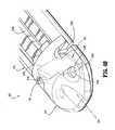
図1は、外科用装置(例えば、外科用ステープリング装置)を示しており、一般に10と参照される。簡略にするために、この開示は主として、使い捨てローディングユニット(「DLU」)16を外科用ステープリング装置10にローディング、係合、結合あるいは接続するためのシステム、方法及び構造に集中する。外科用ステープリング装置10の使用の残りのコンポーネントおよび方法が、米国特許第6,241,139号に開示されている。 FIG. 1 shows a surgical device (eg, a surgical stapling device), generally referred to as 10. For simplicity, this disclosure focuses primarily on systems, methods and structures for loading, engaging, coupling or connecting a disposable loading unit (“DLU”) 16 to the surgical stapling apparatus 10. The remaining components and methods of use of the surgical stapling apparatus 10 are disclosed in US Pat. No. 6,241,139.
外科用ステープリング装置10は、内視鏡装置であり、ハンドルアセンブリ12およびハンドルアセンブリ12から延びる細長い本体14を含んでいる。DLU16は、細長い本体14の遠位端に解放可能に固定されている。この開示は外科用ステープリング装置10とのDLUの使用に関しているが、単使用ローディングユニット(SULU)あるいは他のエンドイフェクタおよび/またはツールアセンブリは、外科用ステープリング装置10と連携して同様に使用され得、本開示の範囲内であることが理解される。 Surgical stapling device 10 is an endoscopic device and includes a
DLU16は、複数の外科用ファスナつまりステープル84(図2)を収納するカートリッジアセンブリ18、およびカートリッジアセンブリに関して可動に固定されたアンビルアセンブリ20を有するツールアセンブリ17を含む。本明細書に示されているように、DLU16は、長さで約30mmから約60mmのDLU内にステープルの6つの線型列を適用するように構成されている。ステープルの任意の数の列を適用するためのDLUが、様々なパターンに配列されたステープルポケットおよび/またはDLUと任意の他の長さ(例えば45mm)を有するエンドイフェクタを有して、想像される。ハンドルアセンブリ12は、固定のハンドル部材22、可動ハンドル部材24およびバレル部分26を含んでいる。 The DLU 16 includes a
回転可能な部材28が、バレル部分26の前方端上にマウントされ、細長い本体14の回転を容易にし、ハンドルアセンブリ12に関してDLU16に取り付けられる。咬合レバー30がまた、回転可能部材28に隣接してバレル部分26の前方端上にマウントされ、ツールアセンブリ17の咬合を容易にする。好ましくは、1対のノブ32が、バレル部分26に沿って可動に配置される。ノブ32は、接近するつまりカートリッジおよび/またはアンビルアセンブリ18、20を閉じるように、遠位に前進させられ、遠ざかるつまりカートリッジおよび/またはアンビルアセンブリ18、20を開くように、近位に待避されられる。 A rotatable member 28 is mounted on the forward end of the
DLU16は、望ましくは、細長い本体14に選択的に除去可能に結合される。DLU16は、細長い本体14の遠位端に解放可能に係合する近位端を有しているハウジング部分36を含む。マウントアセンブリ38は、ハウジング部分36の遠位端に「P」において枢動可能に固定され、ツールアセンブリ17の近位端を受容するように構成され、長手方向の軸に垂直な「P」における軸の周りのツールアセンブリ17のピボット運動が、ツールアセンブリ17の咬合をもたらす。 The DLU 16 is desirably selectively removably coupled to the
図2から図8を総じて参照して、DLU16はマウントアセンブリ40を含んでいる。マウントアセンブリ40は、上側および下側マウント部分、それぞれ40a、40bを含んでいる。中央に配置されたピボット部材42は、上側および下側マウント部分40a、40bのそれぞれから延びている。 Referring generally to FIGS. 2-8, the DLU 16 includes a mount assembly 40. Mount assembly 40 includes upper and lower mount portions, 40a and 40b, respectively. A centrally located pivot member 42 extends from each of the upper and lower mount portions 40a, 40b.
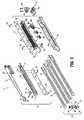
軸駆動アセンブリ50は、カートリッジおよび/またはアンビルアセンブリ18、20に動作可能に関連し、および、カートリッジおよび/またはアンビルアセンブリ18、20の間にスライド可能に配置されている。図2を参照して、軸駆動アセンブリ50は、遠位端54および近位端56を有している細長い駆動ビーム52を含んでいる。駆動ビーム52は、材料の単一シートから、あるいは、多重に積層されたシートから構成され得る。
駆動アセンブリ50の駆動ビーム52の近位端56は、1対の弾性係合フィンガーを含み、弾性係合フィンガーは、DLU16の近位端が外科用ステープリング装置10の細長い本体14と係合する場合、駆動部材(例えば、駆動ロッドあるいは制御ロッド(示されていない))に強度に係合するような大きさに作られ構成されている。制御ロッドは、ハンドルアセンブリ12から駆動アセンブリ50の軸方向の動きを授けるように機能する。 The proximal end 56 of the
駆動アセンブリ50の駆動ビーム52の遠位端54は、I−ビーム60を支持するように構成され適合されている。I−ビーム60は、中央壁部分62と、上側および下側レール部分64a、64bをそれぞれ含んでいる。中央壁部分62の遠位端は、ナイフ刃つまり66様のものを画定する。 The
図2から図10に見られるように、アンビルアセンブリ20は、複数のステープル変形ポケット/キャビティ70a(図9および図10)およびアンビルプレート70の上面に固定されたカバープレート72を有しているアンビルプレート70を含んでおり、キャビティ(示されていない)がそれらの間に画定されている。アンビルプレート70とカバープレート72との間に画定されたキャビティは、I−ビーム60の上側レール部分64aをそれらの中にスライド可能に収容するような大きさに作られている。長手方向のスロット70bは、アンビルプレート70を通って延びており、I−ビーム60の中央壁部分62のそこを通る経路を容易にする。 As seen in FIGS. 2-10, the
動作では、アンビルプレート70の上面が、カム表面70cを画定し、駆動アセンブリ50が長手方向スロット70bを通ってI−ビーム60を進めるとき、I−ビーム60の上側レール部分64aが、アンビルアセンブリ20を組織に対してカムする、促す、およびクランプするように係合する。 In operation, when the upper surface of the
図2から図10を続いて参照して、アンビルプレート70が、アンビルプレート70の近位端近くに、長手方向スロット70bの対抗側に1つずつ形成され配置されるくぼみ70dの近位対を画定する。アンビルプレート70は、アンビルプレート70の遠位端の近くに、長手方向スロット70bの対抗側に1つずつ形成され配置されるくぼみ70eの遠位対を画定する。1つの実施形態では、くぼみ70dの近位対およびくぼみ70eの遠位対のそれぞれのくぼみのうちの少なくとも1つが、非円形であり、好ましくは、アンカー「S」を擦られるように係合、および/または締め付けるように束縛する。 With continued reference to FIGS. 2-10, the
本明細書で使用される用語「アンカー」は、縫合糸、糸、テザー、ストラップ、バンド、線、ワイヤ、ケーブル、ファスナ、びょう、アンカー、あるいは、本明細書に開示された意図した目的に適する任意の他の材料を含むが、それらに限定はされないことが理解される。 As used herein, the term “anchor” is suitable for sutures, threads, tethers, straps, bands, wires, wires, cables, fasteners, caps, anchors, or the intended purpose disclosed herein. It is understood that any other material is included, but not limited thereto.
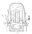
アンビルアセンブリ20は、遠位に向けられたナイフ端74を画定し、アンビルプレート70とカバープレート72との間に画定されたキャビティ内に動作可能に挿入されているナイフ刃74をさらに含む。ナイフ刃74は、くぼみ70eの遠位対の近位に配置された初期のつまり第1の状態、および、くぼみ70eの遠位対の遠位に配置された最終のつまり第2の状態を有している。ナイフ刃74は、係合要素74b(例えば、相補的に係合する要素を選択的に係合するために、その表面に形成されたくぼみ、例えば、カバープレート72の表面から突き出たノブ(示されていない)、あるいは、アンビルアセンブリ20の遠位キャップ76)を含む。係合要素は、互いに間に係合し、ナイフ刃74を固定状態で、初期のつまり第1の状態に維持あるいは保持する。
実施形態において、遠位キャップ76は、その対向する側縁に形成された対向するくぼみ76aの対を含み、対向するくぼみは、カバープレート72がアンビルプレート70と組み立てられたとき、アンビルプレート70に形成されたくぼみ70eの遠位対と整列する。さらに、カバープレート72は、その中に形成された対向するくぼみ72aの対を画定し、対向するくぼみは、カバープレート72がアンビルプレート70と組み立てられたとき、アンビルプレート70に形成されたくぼみ70dの近位対と整列する。 In an embodiment, the
アンビルアセンブリ20は、アンビルプレート70の下面にアンカー「S」によって動作可能に固定された外科用綿撒糸あるいは同様なものである外科用支持「B」をさらに含み、少なくともいくつかのアンビルポケット70aの上に、および/または長手方向スロット70bの長さの少なくとも1部分に重なっている。特に、アンカー「S」は、アンビル支持「B」の遠位部分およびくぼみ70eの遠位対のそれぞれを通ってねじ切られており、かつ、アンカー「S」は、アンビル支持「B」の近位部分およびくぼみ70dの近位対のそれぞれを通ってねじ切られている。 The
特定の実施形態においては、アンカー「S」の第1端は、節、停止部あるいは同様なもの(示されてはいない)を含み、くぼみ70dの近位対の1つのくぼみを通り過ぎないような大きさにされており、アンカー「S」の第2端は、アンビル支持「B」を少なくとも1度は通り過ぎ、横切り、くぼみ70dの近位対のもう一方のくぼみを通って戻る。例えば、アンカー「S」の第2端は、くぼみ70dの近位対のもう一方のくぼみの中に挟み込まれあるいは締めこまれ得、アンカー「S」の第2端を止めて、アンビルプレート70の下面に対してアンビル支持「B」を固定する。同様に、アンカー「S」はアンビル支持「B」を横切って延びてくぼみ70eの遠位対と係合する。 In certain embodiments, the first end of the anchor “S” includes a node, stop or the like (not shown) such that it does not pass through one indentation of the proximal pair of
動作では、以下に詳しい詳細が議論されるように、アンビルプレート70の下面に対して固定されたアンビル支持「B」によって、外科用ステープリング装置10の作動中に駆動アセンブリ50が前進させられる(つまり、最近位の位置から最遠位の位置に動かされる)ので、ナイフ刃66が、近位アンカー「S」の中央部を通ってスライスし、それによって、アンビル支持「B」の近位端をアンビルアセンブリ20から解放する。駆動アセンブリ50がアンビルプレート70の遠位端に近づくとき、I−ビーム60の上側レール64aは、ナイフ刃74に対して当接し、ナイフ刃74を遠位に推し進める。ナイフ刃74が、くぼみ70eの遠位対の近位に配置された初期のつまり第1の状態から、くぼみ70eの遠位対の遠位に配置された最終のつまり第2の状態へ遠位に動かされるとき、そのナイフ縁74aは、遠位アンカー「S」を通ってスライスするつまり切り取り、それによって、アンビル支持「B」の遠位端を、アンビルアセンブリ20から解放する。ナイフ刃74は、くぼみ70eの遠位対の両方のくぼみを通って延びる遠位アンカー「S」を通って切り取る。 In operation, an anvil support “B” secured to the underside of the
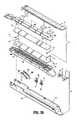
図2−図8および図11−図19に見られるように、カートリッジアセンブリ18は、細長い支持チャネル80aを画定するキャリア80を含む。キャリア80の細長い支持チャネル80aは、中にあるステープルカートリッジ82を選択的に受容するように大きさが決められ構成されている。ステープルカートリッジ82およびキャリア80に沿って形成された対応するタブおよびスロットは、ステープルカートリッジ82をキャリア80の中に保持するように機能する。ステープルカートリッジ82の上に形成され、ステープルカートリッジ82から延びる1対の支持支柱は、キャリア80の側壁に寄りかかるように配置され、キャリア80の支持チャネル80aの中にステープルカートリッジ82をさらに安定にする。ステープルカートリッジ82は、複数のファスナ84およびプッシャ86を受容するために、その中に形成された保持スロット82aを含む。複数の離間した長手方向スロット82bが、ステープルカートリッジ82を通って延びており、作動スレッド90の直立したカムくさび90aを適応する。作動スレッド90は、中央の直立したくさびつまり壁90bを含んでいる。中央壁90bが、そこに形成された遠位ノッチあるいは肩を画定する。 As seen in FIGS. 2-8 and 11-19, the
中央の長手方向スロット82cは、ステープルカートリッジ82の長さの内に形成され、長さに沿って延びており、I−ビームk60の中央の壁部分62のそれを通っての経路を容易にする。外科用ステープル10の動作の間、作動スレッド90は、ステープルカートリッジ82の長手方向スロット82bを通って並進し、カムくさび90aを連続したコンタクトの中にプッシャ92によって進め、プッシャ92が保持スロット82a内で垂直に並進し、ファスナ84(例えばステープル)をスロット82aから、アンビルアセンブリ20のアンビルプレート70のステープル形成キャビティ70aの中に推し進める。 A central
図2および図11−図19の参照の続きで、ステープルカートリッジ82が、長手方向スロット82cの対向する側にそれぞれ互いに、その近位端の近くに、形成され配置されたくぼみ82eの近位対を画定する。ステープルカートリッジ82は、長手方向スロット82cの対向する側にそれぞれ互いに、その遠位端の近くに、形成され配置されたくぼみ82fの遠位対をさらに画定する。1つの実施形態では、くぼみ82cの近位対およびくぼみ82fの遠位対のそれぞれのくぼみのうちの少なくとも1つのくぼみは、非円形に、好ましくは、摩擦的にアンカー「S」を係合する、および/または締め付けるように束縛する。 2 and 11-19, the
カートリッジアセンブリ18は、遠位に配置されたナイフ縁94a(図12−17および19)を画定し、ステープルカートリッジ82の遠位端の近くに画定されたキャビティ82d(図16、17および19)内に動作可能に配置されているナイフ刃94をさらに含む。ナイフ刃94は、ナイフ縁94aの右側および左側を含む。ナイフ刃94は、ステープルカートリッジ82の中に形成されたくぼみ82eの遠位対の近位に配置された初期つまり第1の状態、およびくぼみ82eの遠位対の遠位に配置された最終つまり第2の状態を有している。 The
ナイフ刃94は、選択的に相補的に係合する要素(示されていない)のために、カートリッジアセンブリ18のステープルカートリッジ82の表面から突き出ている、その表面に形成された係合要素(示されていない)を含む。係合要素は、互いに間に係合し、ナイフ刃94を静止状態で、初期つまり第1の状態に維持し保持する。
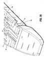
カートリッジアセンブリ18は、動作可能にステープルカートリッジ82の上面にアンカー「S」によって固定された外科用綿撒糸あるいは同様なものである外科用支持「B」をさらに含み、少なくともいくつかのステープルポケット82aの上に、および/または長手方向スロット82cの長さの少なくとも1部分に重なっている。特に、アンカー「S」は、カートリッジ支持「B」の遠位部分およびくぼみ82fの遠位対のそれぞれを通ってねじ切られており、かつ、アンカー「S」は、カートリッジ支持「B」の近位部分およびくぼみ82eの近位対のそれぞれを通ってねじ切られている。 The
1つの特定の実施形態では、それぞれのアンカー「S」の第1端は、節、停止部あるいは同様なもの(示されてはいない)を含み、くぼみ82eの近位対の1つのくぼみを通り過ぎないような大きさにされており、アンカー「S」の第2端は、カートリッジ支持「B」を少なくとも1度は通り過ぎ、横切り、くぼみ82eの近位対のもう一方のくぼみを通って戻る。例えば、アンカー「S」のそれぞれの第2端は、くぼみ82eの近位対のもう一方のくぼみの中に挟み込まれあるいは締めこまれ得、アンカー「S」の第2端を止めて、ステープルカートリッジ82の組織接触面に対してカートリッジ支持「B」を固定する。同様に、アンカー「S」はカートリッジ支持「B」を横切って延びてくぼみ82fの遠位対と係合する。 In one particular embodiment, the first end of each anchor “S” includes a node, stop or the like (not shown) and passes through one indentation in the proximal pair of
動作では、以下に詳しい詳細が議論されるように、ステープルカートリッジ82の組織接触面に対して固定されたカートリッジ支持「B」によって、外科用ステープリング装置10の作動中に駆動アセンブリ50が前進させられる(つまり、最近位の位置から最遠位の位置に動かされる)とき、ナイフ刃66が、近位アンカー「S」の中央部を通ってスライスし、それによって、カートリッジ支持「B」の近位端をカートリッジアセンブリ18から解放する。図18に見られるように、駆動アセンブリ50がステープルカートリッジ82の遠位端に近づくとき、中央の直立くさびの肩90cあるいは、作動スレッド90の壁90bは、ナイフ刃94に対して当接し、ナイフ刃94を遠位に推し進める。ナイフ刃94が、初期のつまり、くぼみ82fの遠位対の近位に配置された第1の状態から、最終状態つまり、くぼみ82fの遠位対の遠位に配置された第2の状態へ遠位に動かされるとき、それのナイフ縁94aが、遠位アンカー「S」を通ってスライスしつまり切断し、それによって、カートリッジ支持「B」の遠位端をカートリッジアセンブリ18から解放する。ナイフ刃94は、くぼみ82fの遠位対の両方のくぼみを通って延びる遠位アンカー「S」を通って切断する。 In operation, the cartridge support “B” secured to the tissue contacting surface of the
駆動アセンブリ50が、最近位位置から最遠位位置に進められるとき、それのナイフ刃66が、アンビル支持「B」およびカートリッジ支持「B」の両方を通って長手方向にスライスつまり切断し、それによって、支持「B」を実質的に半分に分ける。従って、駆動アセンブリ50が、最近位位置から最遠位位置に進められるとき、作動スレット90の直立しているカムくさび90aがプッシャ92を作動し、プッシャ92を保持スロット82a内で縦方向に並進させ、ファスナ84をスロット82aから推し進める。ファスナ84(例えばステープル)が、ステープルカートリッジ82のスロット82aから推し進められるとき、ファスナ84の脚が、アンビル支持「B」とカートリッジ支持「B」の間に挿入された任意の組織(示されない)を通って、アンビル支持「B」およびカートリッジ支持「B」の両方を貫き、通り過ぎ、アンビルアセンブリ20のアンビルプレート70のステープル形成キャビティ70aに対してあるいは中に形成される。 When
本開示によると、アンビル支持「B」および/またはカートリッジ支持「B」が、DLU17のアンビルアセンブリ20あるいはカートリッジアセンブリ18の上に、それぞれプレロードされる(つまり、製造者から)。アンビルアセンブリ20および/またはカートリッジアセンブリ18の、追加のあるいは置き換えの支持「B」が、必要あるいは所望によって、アンビルアセンブリ20あるいはカートリッジアセンブリ18のいずれかに固定され得る。 According to the present disclosure, anvil support “B” and / or cartridge support “B” are preloaded (ie, from the manufacturer) onto the
動作では、外科用ステープリング装置10の細長い本体14の遠位端に結合されたDLU17と、アンビルアセンブリ20およびカートリッジアセンブリ18にそれぞれプレロードされたアンビル支持「B」およびカートリッジ支持「B」とによって、外科用ステープリング装置10が当業者には公知の方法に従って使用される。ひとたび、アンビルアセンブリ20およびカートリッジアセンブリ18が組織の上に挟み込まれると、外科用ステープリング装置10が起動される。外科用ステープリング装置10の起動において、駆動アセンブリ50が最近位位置から最遠位位置に進められる。そうなると、駆動アセンブリ50のナイフ刃66は、アンビルアセンブリ20およびカートリッジアセンブリ18の近位アンカー「S」の中央部を通って、実質的に同時にスライスしつまり切断し、それによって、アンビル支持「B」およびカートリッジ支持「B」の近位端を、それらからそれぞれ解放する。 In operation, the
駆動アセンブリ50が最遠位位置に接近するとき、I−ビーム60の上側レール64aがナイフ刃74に当接し、ナイフ刃74を遠位に推し進め、実質的に同時にあるいはそれに付随して、作動スレッド90の中央直立くさびつまり壁90bの肩90cが、ナイフ刃94に当接し、それを遠位に推し進める。ナイフ刃74が、初期位置から最終位置に遠位に動かされるとき、それのナイフ縁74aはアンビルアセンブリ20の遠位アンカー「S」を通ってスライスし、つまり切断し、それによって、アンビル支持「B」の遠位端を、アンビルアセンブリ20から解放する。ナイフ刃94が、初期位置から最終位置に遠位に動かされるとき、そのナイフ縁94aはカートリッジアセンブリ18の遠位アンカー「S」を通ってスライス、つまり切断し、それによって、カートリッジ支持「B」の遠位端を、カートリッジアセンブリ18から解放する。 When the
また、駆動アセンブリ50のナイフ刃66が、アンビル支持「B」およびカートリッジ支持「B」の両方を通って実質的に同時にスライスするつまり切断し、それによって、支持「B」を実質的に半分に分ける。 Also, the
ここで、図20−32に移ると、本開示の他の実施形態による、外科用ステープリング装置10のDLUが116として示されている。DLU16は、実質的にDLU16と同様であり、本明細書では、構築および動作で異なる部分を識別するのに必要な範囲のみが詳細に議論される。 Turning now to FIGS. 20-32, the DLU of the surgical stapling apparatus 10 is shown as 116 according to another embodiment of the present disclosure. The DLU 16 is substantially similar to the DLU 16 and only the scope necessary to identify different parts in construction and operation will be discussed in detail herein.
図20−25に見られるように、DLU116のアンビルアセンブリ20が、アンビルプレート70の近位端の近くに、長手方向スロット70bの対向する側にそれぞれ互いに形成され配置されたくぼみ70dの近位対を画定し、長手方向スロット70bの対向する側にそれぞれ互いに、アンビルプレート70の遠位端の近くに、形成され配置されたくぼみ70eの遠位対を画定する。図22、24および25で最良に見られるように、くぼみ70dの近位対およびくぼみ70eの遠位対のそれぞれのうちの少なくとも1つのくぼみはノッチ形状であり、ノッチは、その中の縫合糸(糸あるいは同様なもの)を摩擦的に締め、受容し固定するように制限する構造を有している。 As seen in FIGS. 20-25, the
図23に見られるように、ナイフ刃74は、フィンあるいはタブの形状の配向部材74cを含み、配向部材74cは、その下側から延びており、アンビルプレート70の長手方向スロット70bとスライド可能に係合するように構成され適合されている。配向部材74cは、ナイフ刃74の正しいあるいは所望の配向を維持するのを助けるように機能する。例えば、ナイフ刃74の配向部材74cは、ナイフ縁74aを長手方向スロット70bに関して直角方向に実質的に維持する援助になり得る。 As seen in FIG. 23, the
図20、21および26−32に見られるように、DLU116のカートリッジアセンブリ18のステープルカートリッジ82が、長手方向スロット82cの対向する側にそれぞれ互いに、その近位端の近くに、形成され配置されたくぼみ82eの近位対を画定し、長手方向スロット82cの対向する側にそれぞれ互いに、その遠位端の近くに、形成され配置されたくぼみ82fの遠位対を画定する。 As seen in FIGS. 20, 21 and 26-32, the
実施形態では、図20および26に見られるように、ステープルカートリッジ82は、その上面から延びている少なくとも1つのポストを含み得、ステープルカートリッジ82に重なるべき外科用支持「B」は、その中に形成されたそれぞれの相補的アパーチャを含み得ると想定される。この方法では、外科用支持「B」がステープルカートリッジ82の上に配置されたとき、そのアパーチャ(あるいは複数)およびステープルカートリッジ82のポスト(あるいは複数)が互いに協力し、ステープルカートリッジ82に対して、外科用支持「B」を実質的に向きを揃えて整列する。 In an embodiment, as seen in FIGS. 20 and 26, the
ステープルカートリッジ82は、その中のナイフ刃インサート83を選択的に受容するために、その中に形成された遠位のくぼみ82gを画定する。図20、21および26−32に見られるように、ステープルカートリッジ82の遠位くぼみ82gは、平面を画定し、該平面は、その組織接触面に実質的に平行であり、長手方向スロット82cに実質的に位置合わせされた拡張部を含んでいる。
図31に見られるように、ナイフ刃インサート83が、カートリッジアセンブリ18(図2)のナイフ刃74に形成された相補的受容構造74aを瞬時に係合するために、こぶあるいは同様なものの形の突起部83aを含む。突起部83aを有するナイフ刃インサート83が示されているが、ナイフ刃インサート83が、その中に形成されたくぼみつまりへこみ部分を含み得、くぼみは、ナイフ刃74から延びる相補的突起と瞬時に係合するように構成され、適合することが明示されている。 As seen in FIG. 31, the
図32に見られるように、ナイフ刃インサート83は、駆動アセンブリ50によって作動させられるまで、ナイフ刃74を第1の状態に、つまり、ステープルカートリッジ82のくぼみ82fの遠位対の近位に配置されている状態に、維持するように機能する。 As seen in FIG. 32, the knife blade insert 83 places the
ここで、図33に移って、本開示の他の実施形態によると、カートリッジアセンブリ18の遠位端が、通常118で示されている。カートリッジアセンブリ118は、カートリッジアセンブリ18と実質的に同様であり、本明細書では、構成および動作で異なる部分を識別するのに必要な範囲のみが詳細に議論される。 Turning now to FIG. 33, according to another embodiment of the present disclosure, the distal end of the
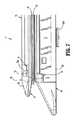
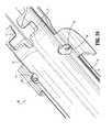
図22、24および25で最良に見られるように、くぼみ70dの近位対およびくぼみ70eの遠位対のそれぞれのうちの少なくとも1つが、ノッチ形状であり、ノッチは、その中の縫合糸(糸あるいは同様なもの)を摩擦的に締め、受容し固定するように束縛する構造を有している。図33に見られるように、カートリッジアセンブリ18は、キャリア80の遠位端あるいはステープルカートリッジ82に動作可能に固定されたナイフ刃を含んでいる。ナイフ刃194がステープルカートリッジ82に支持されている場合、ステープルカートリッジ82が置き換えられるとき、ナイフ刃194は置き換えられる。 As best seen in FIGS. 22, 24 and 25, at least one of each of the proximal pair of
ナイフ刃194は、アーム194aを含み、アーム194aは、キャリア80あるいはステープルカートリッジ82の遠位端の近くに固定された遠位端を有しており、近位端は実質的に外科用ステープリング装置10のハンドルアセンブリ12に向かって延びている。ナイフ刃194は、アーム194aの近位端から、ステープルカートリッジ82の細長いスロット82cに実質的に平行な方向に延びているナイフ縁194bを含む。ナイフ刃194のナイフ縁194bは、ステープルカートリッジ82のくぼみ82fの遠位対の間に実質的に整列されており、ナイフ縁194bは、ステープルカートリッジ82のくぼみ82fの遠位対の間に延びているアンカー「S」と並置されて整列している。ナイフ刃194のアーム194aは、初期状態を有しており、ナイフ縁194bは、ステープルカートリッジ82のくぼみ82fの遠位対の間に延びているアンカー「S」から離間している。 The
動作では、駆動アセンブリ50が遠位に前進させられる場合、作動スレッド90(例えば、中央の直立したくさび90b)は、ナイフ刃94のアーム194aの近位端に対して係合し、それによって、ステープルカートリッジ82のくぼみ82fの遠位対の間に延びているアンカー「S」に向かって、ナイフ刃94のアーム194aの近位端を付勢しカムし、そのナイフ縁194bはアンカー「S」を通って切断し、すなわち切り、外科用支持「B」をステープルカートリッジ82から解放する。 In operation, when the
ナイフ縁194bは、付勢されていない、つまり初期の状態に戻るアーム194aによって生成されたばね力の結果として、ステープルカートリッジ82の中に引っ込む。代替として、図33に見られるように、圧縮されたばねあるいは同様なものである付勢部材195が、キャリア80と作動スレッド90との間にあるいは動作可能にこれらに関連して、挿入され得る。この方法では、作動ストロークを完了させるのに要求される力の除去がされると、付勢部材195が延び、従って作動スレッド90を近位方向に推し進めて、それによってナイフ縁194bがステープルカートリッジ82の中に引っ込むことを可能にする。 The knife edge 194b retracts into the
本明細書で開示されている例示の外科用ステープリング装置と使用するための外科用支持「B」は、同一出願人による米国特許第5,542,594号、第5,908,427号、第5,964,774号、および第6,045,560号に、また、同一出願人による2006年4月20日に出願された米国出願第2006/0085034号、および2006年6月22日に出願された第2006/0135992号に示され記載されており、それぞれの内容全体が参照によって本明細書に援用されている。 Surgical support “B” for use with the exemplary surgical stapling apparatus disclosed herein is disclosed in commonly assigned US Pat. Nos. 5,542,594, 5,908,427, Nos. 5,964,774 and 6,045,560, and US Application No. 2006/0085034, filed Apr. 20, 2006 by the same applicant, and Jun. 22, 2006. No. 2006/0135992 filed and described, the entire contents of each are hereby incorporated by reference.
図を通して、特に図2、図9から図11,図13、図14、図20および図26で見られるように、各外科用支持「B」は、それらの中に形成された離間した孔の近位対および/または、遠位対を提供され得、外科用支持「B」の近位および/または遠位孔は、それぞれ、アンビルプレートおよび/またはステープルカートリッジの近位および/または遠位のくぼみと整列し、および/またはそれらに並置された状態にある。外科用支持「B」の孔は、アンカー「S」によって、アンビルプレートおよび/またはステープルカートリッジへの、外科用支持「B」の、より効率的で容易なアタッチメントを可能にする。 Throughout the drawings, and in particular, as seen in FIGS. 2, 9 through 11, 13, 14, 20, and 26, each surgical support “B” has a spaced aperture formed therein. Proximal and / or distal pairs can be provided, and the proximal and / or distal holes of the surgical support “B” can be proximal and / or distal of the anvil plate and / or staple cartridge, respectively. Aligned with and / or juxtaposed with the indentations. The holes in the surgical support “B” allow a more efficient and easy attachment of the surgical support “B” to the anvil plate and / or staple cartridge by the anchor “S”.
ここで、図34から図36に移ると、外科用ステープリング装置のDLUでの使用のために、本開示の他の実施形態によるアンビルアセンブリが、220として指定されている。アンビルアセンブリ220は、アンビルアセンブリ20と実質的に同様であり、従って、本明細書では、その構築および動作で異なる部分を識別するのに必要な範囲のみが詳細に議論される。 Turning now to FIGS. 34-36, an anvil assembly according to another embodiment of the present disclosure is designated as 220 for use in a DLU of a surgical stapling apparatus. The
図34から図36に見られるように、アンビルアセンブリ220は、それに、特にその遠位端近くに枢動可能に固定されたナイフ刃274を含む。ナイフ刃274は、駆動アセンブリ50(図2)がアンビルアセンブリ20の最遠位位置に進められるとき、アンカー「S」を分断する枢動点の周りに回転するように配置されている。 As seen in FIGS. 34-36, the
詳細には、図34から図36の参照を続けて、アンビルアセンブリ220は、ナイフ刃274と係合するあるいはそれを支持する遠位キャップ276に、カバープレート272に、および/または、アンビルプレート270に形成された枢動点276bを含む。ナイフ刃274は、枢動点276bを枢動可能に係合するように構成され大きさが決められている枢動ウィンドウ274bを画定するローブ274aを含む。枢点276bおよび枢動ウィンドウ274bは、枢動軸「Y」を画定し、枢動軸「Y」は、アンビルプレート270の長手方向スロット270bの長手方向軸「X」から距離をおいて配置されている。 In particular, with continued reference to FIGS. 34-36, the
ナイフ刃274は、アンビルプレート270の長手方向スロット270bと交差して延びているカム縁274c、およびカム縁274cを横断して延びているナイフ縁274dを画定する。ナイフ刃274は、カム縁274cの一部分、および/またはナイフ縁274dの一部分がアンカー「S」と交差して延びるように構成され大きさが決められている。 The
図34および図35に見られるように、ナイフ刃274は、ナイフ縁274dがくぼみ270eを横断しては延びていなく、かつ、アンカー「S」との係合から外れている第1の部分を有している。特に、第1の位置にある場合、ナイフ刃274のナイフ縁270dは、くぼみ270eの近位に延びる部分と、くぼみ270eの遠位に延びる部分とを含む。さらに、第1の位置にある場合、ナイフ刃274のナイフ縁274dは、くぼみ270eの間に配置されている。また、第1の位置にある場合、ナイフ刃274のカム縁274cは、くぼみ270eの近位に延びる少なくとも一部分を含む。 As seen in FIGS. 34 and 35,
図36に見られるように、ナイフ刃274は、ナイフ縁274dがくぼみ270eと交差して延び、かつ、アンカー「S」と係合している第2の位置を有している。特に、第2の位置にある場合、ナイフ刃274のナイフ縁274dは、くぼみ270eを超えて延びるあるいは配置されている部分を含む。 As seen in FIG. 36,
動作では、外科用ステープリング装置10の作動の間、駆動アセンブリ50(図2)が進められる(つまり、最近位位置から最遠位位置に動かされる)とき、駆動アセンブリ50は、ナイフ刃274がアンカー「S」を通ってスライスし、それによって、アンビル支持の遠位端を解放する(図2)。特に、第1の位置のナイフ刃274によって、図35に見られるように、駆動アセンブリ50が遠位に進められるとき、矢印「A」で示されたように、駆動アセンブリ50は、ナイフ刃274のカム縁274cに接触するあるいはそれと係合する。駆動アセンブリ50が遠位にさらに進められるとき、駆動アセンブリ50は、枢動点276bの周りにモーメントを生成し、矢印「B」で示されたように、ナイフ刃274をその周りで回転させる。その際、図36に見られるように、ナイフ刃274のナイフ縁274dは、アンカー「S」を通って進められるあるいはその周りを回転され、従って、アンカー「S」を切断し、アンビル支持の遠位端を解放する(図2)。 In operation, when the drive assembly 50 (FIG. 2) is advanced (ie, moved from the most proximal position to the most distal position) during operation of the surgical stapling apparatus 10, the
ここで、図37〜39に移ると、本開示の他の実施形態によるカートリッジアセンブリが一般に218として指定されている。カートリッジアセンブリ218は、カートリッジアセンブリ18と実質的に同様であり、従って、本明細書では、その構築および動作で異なる部分を識別するのに必要な範囲のみが詳細に議論される。 Turning now to FIGS. 37-39, a cartridge assembly according to another embodiment of the present disclosure is designated generally as 218. The
図37から図39に見られるように、カートリッジアセンブリ218は、それに、特に、その遠位端の近くに、枢動可能に固定されたナイフ刃294を含む。ナイフ刃294は、駆動アセンブリ50(図2)がカートリッジアセンブリ218の最遠位位置に進められるとき、アンカー「S」を分断する枢動点の周りに回転するように配置されている。 As seen in FIGS. 37-39, the
詳細には、図37から図39の参照を続けて、カートリッジアセンブリ218は、ナイフ刃294を枢動可能に係合あるいは支持するために、ナイフ刃インサート283および/またはステープルカートリッジ282の中に形成された枢動点283aを含む。ナイフ刃294は、枢動点283aを枢動可能に係合するように構成され大きさが決められている枢動ウィンドウ294bを画定するローブ294aを含む。枢動点283aおよび枢動ウィンドウ294bは、枢動軸「Y」を画定し、枢動軸「Y」は、ステープルカートリッジ282の長手方向スロット282cの長手方向軸「X」から距離をおいて配置されている。 Specifically, with continued reference to FIGS. 37-39, a
ナイフ刃294は、ステープルカートリッジ282の長手方向スロット282cと交差して延びている背板つまりカム縁294c、およびカム縁294cに平行に延びているナイフ縁294dを画定する。ナイフ刃294は、カム縁294cおよびナイフ縁294dが、アンカー「S」の近位に配置されるように構成され大きさが決められている。 The
図37および図38に見られるように、ナイフ刃294は、ナイフ縁294dがくぼみ282fを横断しては延びていなく、かつ、アンカー「S」との係合から外れている第1の部分を有している。さらに、第1の位置にある場合、ナイフ刃294のナイフ縁294dは、くぼみ282fの近位に配置されている。 As seen in FIGS. 37 and 38, the
図39に見られるように、ナイフ刃294は、ナイフ縁294dがくぼみ282fと交差して延び、かつ、アンカー「S」と係合している第2の位置を有している。具体的には、第2の位置にある場合、ナイフ刃294のナイフ縁294dは、くぼみ270eを超えて延びるあるいは配置されている部分を含む。 As seen in FIG. 39, the
動作では、外科用ステープリング装置10の作動の間、駆動アセンブリ50(図2)が進められる(つまり、最近位位置から最遠位位置に動かされる)とき、駆動アセンブリ50は、ナイフ刃294がアンカー「S」を通ってスライスし、それによって、カートリッジ支持「B」の遠位端を解放する。具体的には、第1の位置のナイフ刃294によって、図38に見られるように、駆動アセンブリ50が遠位に進められるとき、矢印「A」で示されているように、駆動アセンブリ50は、ナイフ刃294のカム縁294cに接触するあるいはそれと係合する。駆動アセンブリ50が遠位にさらに進められるとき、駆動アセンブリ50は、枢動点283aの周りにモーメントを生成し、矢印「B」で示されたように、ナイフ刃294をその周りで回転させる。その際、図39に見られるように、ナイフ刃294のナイフ縁294dは、アンカー「S」を通って進められるあるいはその周りを回転され、従って、アンカー「S」を切断し、カートリッジ支持「B」の遠位端を解放する。 In operation, when the drive assembly 50 (FIG. 2) is advanced (ie, moved from the most proximal position to the most distal position) during operation of the surgical stapling apparatus 10, the
ここで、図40〜42に移ると、本開示のさらに他の実施形態によるアンビルアセンブリが320として指定されている。アンビルアセンブリ320は、アンビルセンブリ220と実質的に同様であり、従って、本明細書では、その構築および動作で異なる部分を識別するのに必要な範囲のみが詳細に議論される。 Turning now to FIGS. 40-42, an anvil assembly according to yet another embodiment of the present disclosure is designated as 320. The
図40〜42に見られるように、アンビルアセンブリ320は、それに枢動的に固定されたナイフ刃374を、具体的には、その遠位端の近くに、含む。ナイフ刃374は、枢動点の周りに回転し、駆動アセンブリ50(図2)が、アンビルアセンブリ320の最遠位位置に進められるとき、アンカー「S]を切断するように配置されている。 As seen in FIGS. 40-42, the
具体的には、図40から図42の参照を続けて、アンビルアセンブリ320は、ナイフ刃374を枢動可能に係合あるいは支持するために、カバープレート(示されていない)の中に、および/またはアンビルプレート370の中に形成された枢動点376bを含む。ナイフ刃374は、枢動点376bを枢動可能に係合するように構成され大きさが決められている枢動ウィンドウ374bを画定するローブ374aを含む。枢動点376bおよび枢動ウィンドウ374bは、枢動軸「Y」を画定し、枢動軸「Y」は、アンビルプレート370の長手方向スロット370bの長手方向軸「X」から距離をおいて配置されている。 Specifically, with continued reference to FIGS. 40-42, the
ナイフ刃374は、アンビルプレート370の長手方向スロット370bと交差して延びているカム縁374c、およびカム縁374cを横切って延びているナイフ縁374dを画定する。ナイフ刃374は、カム縁374cが、アンカー「S」の近位に配置され、ナイフ縁374dの一部分がアンカー「S」と交差して延びるように、構成され大きさが決められている。 The
図40および図41に見られるように、ナイフ刃374は、ナイフ縁374dがくぼみ370eを横断しては延びていなく、アンカー「S」と係合している第1の位置を有する。具体的には、第1の位置にある場合、ナイフ刃374のナイフ縁374dは、くぼみ370eの近位に延びる部分を含む。また、第1の位置にある場合、ナイフ刃374のカム縁374cは、くぼみ370eの近位に配置されている。 As seen in FIGS. 40 and 41,
図42に見られるように、ナイフ刃374は、ナイフ縁374dがくぼみ370eと交差して延び、かつ、アンカー「S」と係合している第2の位置を有している。具体的には、第2の位置にある場合、ナイフ刃374のナイフ縁374dは、くぼみ370eを超えて延びるあるいは配置されている部分を含む。 As seen in FIG. 42,
動作では、外科用ステープリング装置10の作動の間、駆動アセンブリ50(図2)が進められる(つまり、最近位位置から最遠位位置に動かされる)とき、駆動アセンブリ50は、ナイフ刃374がアンカー「S」を通ってスライスし、それによって、アンビル支持の遠位端を解放する(図2)。具体的には、第1の位置のナイフ刃374によって、図41に見られるように、駆動アセンブリ50が遠位に進められるとき、矢印「A」で示されているように、駆動アセンブリ50は、ナイフ刃374のカム縁374cに接触するあるいはそれと係合する。駆動アセンブリ50が遠位にさらに進められるとき、駆動アセンブリ50は、枢動点376bの周りにモーメントを生成し、矢印「B」で示されたように、ナイフ刃374をその周りで回転させる。その際、図42に見られるように、ナイフ刃374のナイフ縁374dは、アンカー「S」を通って進められるあるいはその周りを回転され、従って、アンカー「S」を切断し、アンビル支持の遠位端を解放する(図2)。 In operation, when the drive assembly 50 (FIG. 2) is advanced (ie, moved from the most proximal position to the most distal position) during operation of the surgical stapling apparatus 10, the
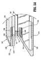
ここで、図43〜45に移ると、本開示の他の実施形態によるカートリッジアセンブリが318として指定されている。カートリッジアセンブリ318は、カートリッジアセンブリ218と実質的に同様であり、従って、本明細書では、その構築および動作で異なる部分を識別するのに必要な範囲のみが詳細に議論される。 Turning now to FIGS. 43-45, a cartridge assembly according to another embodiment of the present disclosure is designated as 318. The
図43〜45に見られるように、カートリッジアセンブリ318は、それに、具体的にはその遠位端の近くに枢動可能に固定されたナイフ刃394を含む。ナイフ刃394は、駆動アセンブリ50(図2)が、カートリッジアセンブリ318の中の最遠位位置に進められるとき、枢動点の周りに回転し、アンカー「S」を切断するように配置されている。 As seen in FIGS. 43-45, the
具体的には、図43〜図45の参照を続けて、カートリッジアセンブリ318は、ナイフ刃394を枢動可能に係合あるいは支持するために、ナイフ刃インサート383の中に、および/または、ステープルカートリッジ382の中に形成された枢動点383aを含む。ナイフ刃394は、枢動点383aを枢動可能に係合するように構成され大きさが決められている枢動ウィンドウ394bを画定するローブ394aを含む。枢動点383aおよび枢動ウィンドウ394bは、枢動軸「Y」を画定し、枢動軸「Y」は、ステープルカートリッジ382の長手方向スロット382cの長手方向軸「X」から距離をおいて配置されている。 Specifically, with continued reference to FIGS. 43-45, the
ナイフ刃394は、ステープルカートリッジ382の長手方向スロット382cと交差して延びている背板つまりカム縁394c、およびカム縁394cに平行に延びているナイフ縁394dを画定する。ナイフ刃394は、カム縁394cおよびナイフ縁394dが、アンカー「S」の近位に配置されるように構成され大きさが決められている。 The knife blade 394 defines a back plate or
図43および図44に見られるように、ナイフ刃394は、ナイフ縁394dがくぼみ382fを横断しては延びていなく、アンカー「S」との係合から外れている第1の位置を有する。具体的には、第1の位置にある場合、ナイフ刃394のナイフ縁394dは、くぼみ382fの近位に配置されている。 As seen in FIGS. 43 and 44, the knife blade 394 has a first position in which the
図45に見られるように、ナイフ刃394は、ナイフ縁394dがくぼみ382fと交差して延び、かつ、アンカー「S」と係合している第2の位置を有している。具体的には、第2の位置にある場合、ナイフ刃394のナイフ縁394dは、くぼみ382fを超えて延びるあるいは配置されている部分を含む。 As seen in FIG. 45, knife blade 394 has a second position in which
動作では、外科用ステープリング装置10の作動の間、駆動アセンブリ50(図2)が進められる(つまり、最近位位置から最遠位位置に動かされる)とき、駆動アセンブリ50は、作動スレッド90をナイフ刃394の中に押し込み、ナイフ刃394がアンカー「S」を通ってスライスし、それによって、カートリッジ支持「B」の遠位端を解放する。具体的には、第1の位置のナイフ刃394によって、図44に見られるように、駆動アセンブリ50が遠位に進められるとき、矢印「A」で示されているように、駆動アセンブリ50が作動スレッド90をナイフ刃394のカム縁394cに接触させるあるいはそれと係合させる。駆動アセンブリ50が遠位にさらに進められるとき、作動スレッド90は、枢動点383aの周りにモーメントを生成し、矢印「B」で示されたように、ナイフ刃394をその周りで回転させる。その際、図45に見られるように、ナイフ刃394のナイフ縁394dは、アンカー「S」を通って進められあるいはその周りを回転され、従って、アンカー「S」を切断し、カートリッジ支持「B」の遠位端を解放する。 In operation, when the drive assembly 50 (FIG. 2) is advanced (ie, moved from the most proximal position to the most distal position) during operation of the surgical stapling apparatus 10, the
ここで、図46に移ると、本開示のさらに他の実施形態による、外科用ステープリング装置のDLUに使用のためのアンビルアセンブリが、420として指定されている。アンビルアセンブリ420は、アンビルアセンブリ220および320と実質的に同様であり、従って、本明細書では、その構築および動作で異なる部分を識別するのに必要な範囲のみが詳細に議論される。 Turning now to FIG. 46, an anvil assembly for use in a DLU of a surgical stapling apparatus is designated as 420, according to yet another embodiment of the present disclosure.
図46に見られるように、アンビルアセンブリ420は、それに、具体的にはその遠位端の近くに枢動可能に固定されたナイフ刃474を含む。ナイフ刃474は、駆動アセンブリ50(図2)が、アンビルアセンブリ420の中の最遠位位置に進められるとき、枢動点の周りに回転し、アンカー「S」を切断するように配置されている。 As seen in FIG. 46, the
具体的には、図46の参照を続けて、アンビルアセンブリ420は、ナイフ刃474を枢動可能に係合あるいは支持するために、遠位キャップ476の中に、カバープレート(示されていない)の中に、および/または、アンビルプレート470の中に形成された枢動点476bを含む。ナイフ刃474は、枢動点476bを枢動可能に係合するように構成され大きさが決められている枢動ウィンドウ474bを画定するローブ474aを含む。枢動点476bおよび枢動ウィンドウ474bは、枢動軸「Y」を画定し、枢動軸「Y」は、アンビルプレート470の長手方向スロット470bの長手方向軸「X」から距離をおいて配置されている。 Specifically, with continued reference to FIG. 46, the
ナイフ刃474は、アンビルプレート470の長手方向スロット470bと交差して延びているカム縁474c、およびカム縁474cを横切って延びているナイフ縁474dを画定する。ナイフ刃474は、カム縁474cがアンカー(示されていない)の近位に配置されるように構成され大きさが決められており、ナイフ縁474dの一部分がアンカーと交差して延びている。 The
図46に見られるように、ナイフ刃474は、ナイフ縁474dがくぼみ470eを横断しては延びていなく、アンカーとの係合から外れている第1の位置を有する。具体的には、第1の位置にある場合、ナイフ刃474のナイフ縁474dは、くぼみ470eの近位に延びている部分、およびくぼみ470eの遠位に延びている部分を含む。また、第1の位置にある場合、ナイフ刃474のカム縁474cは、くぼみ470eの近位に配置されている。 As seen in FIG. 46,
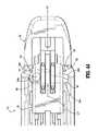
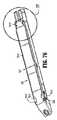
ここで、図47〜図75に移ると、内視鏡外科用ステープリング装置を使用するあるいは接続するように構成されたエンドイフェクタが、一般に1000として指定されている。エンドイフェクタ1000は、複数の外科用ファスナあるいはステープル1228(図48)を収納するカートリッジアセンブリ1200および、カートリッジアセンブリ1200に関して可動に固定されたアンビルアセンブリ1300を含む。エンドイフェクタ1000は、約30mmから約60mmの長さである。エンドイフェクタ1000は、ステープルの6つの線型列を適用するように構成されている。 Turning now to FIGS. 47-75, an end effector configured to use or connect to an endoscopic surgical stapling apparatus is generally designated as 1000.
図47から49に見られるように、エンドイフェクタ1000は、バンドルアセンブリ(示されていない)と選択的に接続するように構成された使い捨て負荷ユニットとして構成されている。 As seen in FIGS. 47-49,
図49に見られるように、エンドイフェクタ1000は、カートリッジアセンブリ1200とアンビルアセンブリ1300とに動作的に関連しそれらの間にスライド可能に配置された軸方向駆動アセンブリ1150を含む。軸方向駆動アセンブリ1150は、遠位端1152aおよび近位端1152bを有する細長い駆動ビーム1152を含む。駆動ビーム1152は、複数の積層されたビームから構成されている。 As seen in FIG. 49,
駆動ビーム1152の近位端1152bは、弾性係合フィンガーの対として形成されており、エンドイフェクタ1000の近位端がバンドルアセンブリに接続される場合、弾性係合フィンガーは駆動ロッドあるいは制御ロッド(示されていない)を取り付け可能に係合するように構成されている。 The
駆動ビーム1152の遠位端1152aは、それから横断して延びる上側レール1154aおよび下側レール1154bを含むI−ビームとして構成されている。駆動ビーム1152の中央ビームの遠位端は、ナイフ刃1156を画定する。 The
図49から図62に見られるように、カートリッジアセンブリ1200は細長い支持チャネル1212を画定するキャリア1210を含む。キャリア1210の細長い支持チャネル1212は、その中のステープルカートリッジ1220を選択的に受容するように大きさが決められ構成されている。ステープルカートリッジ1220およびキャリア1210に沿って形成された対応するタブおよびスロットは、ステープルカートリッジ1220をキャリア1210の内部に保持する。ステープルカートリッジ1220は、その中に形成された、複数の外科用ステープル1224およびプッシャ1226を受容するための保持スロット1222を含む。 As seen in FIGS. 49-62, the
図49、50、53および55に見られるように、カートリッジアセンブリ1200は、ステープルカートリッジ1220とキャリア1210との間にスライド可能に配置された作動スレッド1228をさらに含む。作動スレッド1228は、1対の外側カムくさびあるいは壁1228bによって横にされた中央の直立くさびあるいは壁1228aを含む。中央壁1228aは、その中に形成された遠位ノッチあるいは肩1228cを画定する。 As seen in FIGS. 49, 50, 53 and 55, the
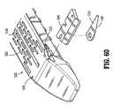
図49および図60に見られるように、中央の長手方向スロット1234はステープルカートリッジ1220の長さの中に形成され、長さに沿って延びており、駆動ビーム1152の経路がそれを通ることを可能にする。外科用ステープラの動作の間、作動スレッド1228は、ステープルカートリッジ1220およびキャリア1210に沿って並進し、外側カムくさび1228bをプッシャ1226との連続した接触に進め、プッシャ1226が、保持スロット1222内で縦方向に並進し、ステープル1224をスロット1222から、アンビルアセンブリ1300のアンビルプレート1310のステープル形成キャビティ1312の中に追いやる(図66)。 As seen in FIGS. 49 and 60, the central
図56〜図59を参照して、ステープルカートリッジ1220は、その近位端近くに形成され、長手方向スロット1234の対向する側にそれぞれ互いに配置されたくぼみ1236の近位対を画定する。ステープルカートリッジ1220は、その遠位端の近くに形成され、長手方向スロット1234の対向する側にそれぞれ互いに配置されたくぼみ1238の遠位対をさらに画定する。図57〜図59に見られるように、くぼみ1236の近位対のそれぞれのうちの少なくとも1つのくぼみ、およびくぼみ1238の遠位対は、限られたプロファイルを有しているスロットあるいはノッチ形状であり、縫合「S」を摩擦的に係合および/または、挟み込む。 Referring to FIGS. 56-59,
図49、53、54、57および60〜62に見られるように、カートリッジアセンブリ1200は、遠位に配向されたナイフ縁1242を画定するナイフ刃1240を含み、ステープルカートリッジ1220内に枢動可能に支持されている。ナイフ刃1240は、ナイフ縁1242がくぼみ1238の遠位対の1つの近位に配置されている初期つまり第1の状態と、ナイフ縁1242がくぼみ1238の遠位対の1つの遠位に配置されている最終のつまり第2の状態とを有している。 49, 53, 54, 57 and 60-62, the
カートリッジアセンブリ1200は、ステープルカートリッジ1220内にくぼみ1238の遠位対に関連した位置で支持されたナイフ刃ハウジング1246を含む。図61に見られるように、ナイフ刃ハウジング1246は、その上にナイフ刃1240が回転可能に接続されたハブ1246aを含む。
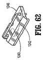
図49、51、52および54〜59で見られるように、カートリッジアセンブリ1200は、ステープルカートリッジ1220の上面に、縫合糸「S」によって、動作可能に固定された外科用カートリッジ支持「B1」をさらに含み、保持スロット1222の少なくともいくつかに、および/または長手方向スロット1234の長さの少なくとも一部分に重なる。外科用カートリッジ支持「B1」は、舌状の形をした近位端部分「B1a」、および、舌状の形をした遠位端部分「B1b」を含み、舌状の形をした近位端部分「B1a」は、外科用カートリッジ支持「B1」の横幅よりも小さい横幅の大きさを有しており、舌状の形をした遠位端部分「B1b」は、外科用カートリッジ支持「B1」の横幅よりも小さい横幅の大きさを有している。外科用カートリッジ支持「B1」の近位端部分「B1a」は、その中のステープルカートリッジ1220の受容ポスト1252のために、その中に形成された1対のアパーチャ「B1c」を画定する。第1の縫合糸「S1」は、くぼみ1238の遠位対のそれぞれを通って、および、カートリッジ支持「B1」の遠位舌状「B1b」の回りに/上に、ねじ切られている。第2の縫合糸「S2」は、くぼみ1236の近位対のそれぞれを通って、および、カートリッジ支持「B1」の近位舌状「B1b」の回りに/上に、ねじ切られている。 49, 51, 52 and 54-59, the
それぞれの縫合糸「S1、S2」の第1の端は、くぼみ1236、1238の近位対および遠位対のそれぞれのくぼみ内に留められ、あるいは、固定されており、それぞれの縫合糸「S1、S2」の第2の端は、カートリッジ支持「B1」のそれぞれの遠位舌状および近位舌状「B1b、B1a」を横断して通り過ぎ、くぼみ1236、1238の近位対および遠位対のそれぞれの他のくぼみ内に留められ、あるいは、固定されている。 The first ends of the respective sutures “S1, S2” are fastened or fixed in the respective recesses of the proximal and distal pairs of the
図49、56および58に見られるように、ステープルカートリッジ1220は、長手方向スロット1234の対向する側に配置された離間したポスト1252の対を含む。ポスト1252は、近位縫合糸「S2」の遠位におよびそれに隣接して配置されている。ポスト1252は、カートリッジ支持「B1」内に形成された開口部に受容されている。ポスト1252は、駆動アセンブリ1150が遠位に動かされるとき、ステープルカートリッジ1220に関してカートリッジ支持「B1」の位置を維持するように機能する。ポスト1252は、駆動アセンブリ1150が遠位に動かされるとき、近位縫合糸「S2」を力づけるように機能する。 As seen in FIGS. 49, 56 and 58,
図49、51〜55および63〜67に見られるように、アンビルアセンブリ1300は、複数のステープル変形ポケット/キャビティ1312のアンビルプレート1310(図66)およびアンビルプレート1310の最上面に固定されたカバープレート1320を含み、キャビティ1313は、それらの間に画定されている。アンビルプレート1310とカバープレート1320との間に画定されたキャビティは、その中の駆動ビーム1152の上側レール部分をスライド可能に受容するような大きさにされている。長手方向スロット1314は、アンビルプレート1310を通って延びており、それを通る駆動ビーム1152の経路を可能にする。 As seen in FIGS. 49, 51-55 and 63-67, the
動作では、アンビルプレート1310の上面が、カム表面1310aを画定し、駆動アセンブリ1150が長手方向スロット1314を通って駆動ビーム1152を進めるとき、駆動ビーム1152の上側レール部分1154aがカム表面1310aに対して、アンビルアセンブリ1300を組織に対してカムする、促す、およびクランプするように係合する。 In operation, the upper surface of the
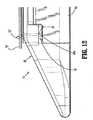
図49、51、52および63〜67の参照の続きで、アンビルプレート1310は、長手方向スロット1314の対向する側にそれぞれ互いに、アンビルプレート1310の近位端の近くに形成され配置されたくぼみ1316の近位対を画定する。アンビルプレート1310は、長手方向スロット1314の対向する側にそれぞれ互いに、アンビルプレート1310の遠位端の近くに形成され配置されたくぼみ1318の近位対を画定する。くぼみ1316の近位対およびくぼみ1318の遠位対のそれぞれのうちの少なくとも1つのくぼみは、制限プロファイルを有するスロットあるいはノッチの形状であり、縫合糸「S」を摩擦的に係合する、および/または挟み込む。 Continuing with reference to FIGS. 49, 51, 52 and 63-67, the
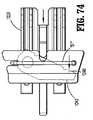
図49、51〜54および64〜67に見られるように、アンビルアセンブリ1300は、遠位に配向されたナイフ縁1332を画定するナイフ刃1330をさらに含み、アンビルプレート1310とカバープレート1320との間に画定されたキャビティの内に、枢動可能に挿入されている。ナイフ刃1330は、ナイフ縁1332がくぼみ1318の遠位対のうちの1つの近位に配置されている初期のつまり第1の状態、およびナイフ縁1332がくぼみ1318の遠位対の1つの遠位に配置されている最終のつまり第2の状態を有している。 As seen in FIGS. 49, 51-54 and 64-67, the
図49、51〜54および64〜67に見られるように、アンビルアセンブリ1300は、アンビルプレート1310とカバープレート1320との間でくぼみ1318の遠位対に関連した位置で支持されたナイフ刃ハウジング1336を含む。図64および67に見られるように、ナイフ刃ハウジング1336は、ナイフ刃1330が回転可能に接続されたハブ1336aを含む。 As seen in FIGS. 49, 51-54 and 64-67, the
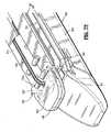
アンビルアセンブリ1300は、アンビルプレート1310の下面に動作的に固定された外科用アンビル支持「B2」をさらに含み、縫合糸「S」によってアンビルポケット1312aの少なくともいくつか、および/または、長手方向スロット1314の長さの少なくとも一部分と重なっている。外科用アンビル支持「B2」は、舌状の形状をした近位端部分「B2a」および舌状の形状をした遠位部分「B2b」を含み、舌状の形状をした近位端部分「B2a」は、外科用カートリッジ支持「B2」の横幅よりも小さい横幅の大きさを有しており、舌状の形状をした遠位端部分「B2b」は、外科用アンビル支持「B2」の横幅よりも小さい横幅を有している。第1の縫合糸「S3」は、くぼみ1318の遠位対のそれぞれを通ってねじ切られており、第2の縫合糸「S4」は、くぼみ1316の近位対のそれぞれを通ってねじ切られている。
縫合糸「S3」の第1の端は、くぼみ1318の遠位対のくぼみ内に留められ、あるいは、固定されており、縫合糸「S3」の第2の端は、アンビル支持「B2」の遠位舌状「B2b」の周りを/の上を通り過ぎ、アンビル支持「B2」を横断的にそれを横切り、くぼみ1318の遠位対のもう一方のくぼみ内に留められ、あるいは、固定されている。 The first end of the suture “S3” is fastened or secured within the recess of the distal pair of
縫合糸「S4」の第1の端は、くぼみ1316の近位対のくぼみ内に留められ、縫合糸「S4」の第2の端は、アンビル支持「B2」の近位舌状「B2a」の周りを/の上を通り過ぎ、くぼみ1316の近位対のもう一方のくぼみ内に留められ、あるいは、固定されている。 The first end of the suture “S4” is retained within the proximal pair of indentations of the
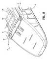
図47〜49、51、63および65〜67に見られるように、アンビルアセンブリ1300のカバープレート1320は、アンビルプレート1310の方向に延びている1対の壁1322を含む。壁1322は、カバープレート1320の近位端の近くに形成され、その対向する側の縁から延びている。壁1322は、カートリッジアセンブリ1200およびアンビルアセンブリ1300が閉じたあるいは留められた状態にあるとき、壁1322は、その間に画定された組織ギャップを渡って延びる。壁1322は、組織が停止する場合、エンドイフェクタ1000の留めあるいは閉止の間、組織が近位方向に流れることを禁止するように機能する。 47-49, 51, 63 and 65-67, the
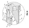
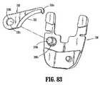
動作では、図68〜72に見られるように、アンビルプレート1310の下面に対して固定されたアンビル支持「B2」によって、外科用ステープリング装置の作動の間、駆動アセンブリ1150が進められるとき(例えば、最近位位置から最遠位位置へ動かされる)、ナイフ刃1156は、縫合糸「S4」の中央部を通ってスライスし、それによって、アンビル支持「B2」の近位端をアンビルアセンブリ1300から解放する。駆動アセンブリ1150はアンビルアセンブリ1300の遠位端に近づくとき、駆動ビーム1152の上側レール部分がナイフ刃1330に当接し、ナイフ刃1330を遠位に回転を推し進める。ナイフ刃1330が遠位に回転させられるとき、ナイフ縁1332は、くぼみ1318の遠位対の1つの近位位置に配置された初期つまり第1の位置から、くぼみ1318の遠位対の1つの遠位に配置された最終つまり第2の位置へ回転させられる。その場合、ナイフ刃1332は、縫合糸「S3」を通ってスライスする、つまり、切断し、それによって、アンビル支持「B2」をアンビルアセンブリ1300から解放する。 In operation, as seen in FIGS. 68-72, when the
それに附随して、動作では、図68〜75に見られるように、ステープルカートリッジ1220の組織接触面に対して固定されたカートリッジ支持「B1」によって、外科用ステープリング装置の作動中に、駆動アセンブリ1150が前進させられるとき(例えば、最近位位置から最遠位位置に動かされる)、ナイフ刃1156は、近位縫合糸「S2」の中央部分を通ってスライスし、それによって、カートリッジ支持「B1」の近位端をカートリッジアセンブリ1200から解放する。 Concomitantly, in operation, as seen in FIGS. 68-75, during operation of the surgical stapling apparatus, the drive assembly is secured by cartridge support “B1” secured to the tissue contacting surface of
駆動アセンブリ1150がステープルカートリッジ1220の遠位端に近づくとき、作動スレッド1228の中央の直立くさびつまり壁1228aの肩1228cがナイフ刃1240に対して当接し、ナイフ刃1240を遠位に推し進め、遠位に回転する。ナイフ刃1240が遠位に回転させられるとき、ナイフ縁1242は、くぼみ1238の遠位対の1つの近位に配置された初期つまり第1の状態から、くぼみ1238の遠位対の1つの遠位に配置された最終つまり第2の状態へ回転させられる。その場合、ナイフ縁1242は、遠位縫合糸「S1」を通ってスライスし、つまり切断し、それによって、カートリッジ支持「B1」の遠位端をカートリッジアセンブリ1200から解放する。 As the
駆動アセンブリ1150が最近位位置から最遠位位置に近づくとき、そのナイフ刃1156は、カートリッジ支持「B1」およびアンビル支持「B」の両方を通ってスライスし、つまり、切断し、それによって、支持「B1、B2」を実質的に半分に分離する。さらに、駆動アセンブリ1150が最近位位置から最遠位位置に進められるとき、作動スレッド1228の直立カムくさび1228bが、プッシャ1226を作動し、プッシャ1226が、保持スロット1222内で垂直方向に並進され、ステープル1224をスロット1222から推し進められる。ステープル1224が、ステープルカートリッジ1220のスロット1222から推し進められるとき、ステープル1224の脚はカートリッジ支持「B1」およびアンビル支持「B2」の両方を通って、カートリッジ支持「B1」とアンビル支持「B2」との間に挿入された任意の組織(示されていない)を介して、貫通し通り過ぎ、アンビルアセンブリ1300のアンビルプレート1310のステープル変形ポケット1312に対してあるいはその中に形成される。 As
外科用支持「B1、B2」はそれぞれ適切な生体適合および生体吸収性材料から加工されている。外科用支持「B1、B2」はそれぞれ、液体を保持しない非吸収性材料から加工されている。外科用支持「B1、B2」はそれぞれ、GLYCOMETER631(ブロック共重合体)から作られた「BIOSYN」から、グリコリド、ジオキサノンおよびトリメチレン炭酸塩からなる合成ポリマから、加工されている。 The surgical supports “B1, B2” are each fabricated from a suitable biocompatible and bioabsorbable material. The surgical supports “B1, B2” are each fabricated from a non-absorbable material that does not retain liquid. Surgical supports “B1, B2” are each fabricated from “BIOSYN” made from GLYCOMTER 631 (block copolymer) and from a synthetic polymer composed of glycolide, dioxanone and trimethylene carbonate.
結果の共重合体の1ブロックは、p−ジオキサノン(1,4ジオキサン−2オン)およびトリメチレン炭酸塩(1,3ジオキサン−2オン)から誘導されたランダムに組み合わされたユニットを含む。共重合体の第2ブロックは、グリコリドおよびp−ジオキサノンから誘導されたランダムに組み合わされたユニットを含む。結果の共重合体は、約60%のグリコリド、約14%のジオキサン、および約26%のトリメチレン炭酸塩を含有する、ABAトリブロックターポリマである。 One block of the resulting copolymer contains randomly combined units derived from p-dioxanone (1,4 dioxane-2one) and trimethylene carbonate (1,3 dioxane-2one). The second block of the copolymer contains randomly combined units derived from glycolide and p-dioxanone. The resulting copolymer is an ABA triblock terpolymer containing about 60% glycolide, about 14% dioxane, and about 26% trimethylene carbonate.
枢動点の周りに咬合できるエンドイフェクタ1000が、図47および48に示されている。カートリッジアセンブリ1200およびアンビルアセンブリ1300は、非咬合SULUを形成し得る。 An
ここで、図76および77に移って、本開示の他の実施形態による外科用カートリッジ支持「B1」が、ステープルカートリッジ220の組織側に動作的に固定されている。外科用カートリッジ支持「B1」は、舌の形状の近位端部分「B1b」を含み、舌の形状の近位端部分「B1b」は、外科用カートリッジ支持「B1」の中央本体部分「B1a」の横幅よりも小さい横幅の大きさを有している。遠位端部分「B1c」は、舌の形状の遠位端部分を含み、外科用カートリッジ支持「B1」の中央本体部分「B1a」の横幅よりも小さい横幅の大きさを有している。 Turning now to FIGS. 76 and 77, a surgical cartridge support “B1” according to another embodiment of the present disclosure is operatively secured to the tissue side of the
図76および77の外科用カートリッジ支持「B1」の近位舌「B1b」は、その裏側縁に形成された横方向ノッチ対「B1d、B1e」、および、その裏側縁に横方向ノッチ「B1d、B1e」の間に形成され、外科用カートリッジ支持「B1」の中央線に沿って配置された中央ノッチ対「B1f」を画定する。横方向ノッチ「B1d、B1e」は、ステープルカートリッジ220から突き出た形状のポスト252を受容する大きさにされている。中央ノッチ「B1f」は、外科用カートリッジ支持「B1」の切断の間、ナイフのリード入口を提供するために、三角のつまりV型の形状構成を有している。 The proximal tongue “B1b” of the surgical cartridge support “B1” of FIGS. 76 and 77 has a transverse notch pair “B1d, B1e” formed on its back edge, and a transverse notch “B1d,” on its back edge. B1e "defines a pair of central notches" B1f "formed along the centerline of the surgical cartridge support" B1 ". The lateral notches “B1d, B1e” are sized to receive
図76および77の外科用カートリッジ支持「B1」は、本体部分「B1a」の横側縁に、その近位端の近くで形成された横方向くぼみ「B1h、B1i」、および、本体部分「B1a」の横側縁にその遠位端で形成された、1対の横方向くぼみ「B1j、B1k」をさらに含む。それぞれのくぼみは、実質的に三角形であり、ステープルカートリッジ220のくぼみ236、238のそれぞれの近位および遠位対を超えて延びる大きさである。 The surgical cartridge support “B1” of FIGS. 76 and 77 has a lateral indentation “B1h, B1i” formed near its proximal end at the lateral edge of the body portion “B1a” and the body portion “B1a”. Further includes a pair of lateral indentations “B1j, B1k” formed at its distal end at the lateral edge of “”. Each indentation is substantially triangular and is sized to extend beyond the respective proximal and distal pairs of
図78〜80に見られるように、ステープルカートリッジ220は、中央の長手方向スロット234、および、中央の長手方向スロット234のいずれかの側に形成されたステープル保持スロット222の複数の列を画定する。ステープルカートリッジ220は、その上面から突き出る1対の近位パッド220a、220bを含む。パッド220a、220bは、長手方向スロット234の対抗する側に、その近位端近くに形成されている。ステープルカートリッジ220は、その上面から突き出る遠位パッド220cをさらに含む。パッド220cは、長手方向スロット234の遠位に配置されている。使用では、パッド220a〜220cは、外科用カートリッジ支持「B1」が縫合糸によってそれに締められるとき、外科用カートリッジ支持「B1」とステープルカートリッジ220との間のフリップ効果を増強する。 As seen in FIGS. 78-80, the
ここで、図81に移ると、本開示の他の実施形態による外科用アンビル支持「B2」が、アンビルアセンブリ300のアンビルプレート310の組織側に動作的に固定されて示されている。図81の外科用アンビル支持「B2」は、舌の形状の近位端部分「B2b」、および舌の形状の遠位端部分「B2c」を含んでおり、近位端部分「B2b」は、外科用アンビル支持「B2」の中央本体部分「B2a」の横幅の大きさより小さい横幅サイズを有しており、遠位部分「B2c」も、外科用アンビル支持「B2」の中央本体部分「B2a」の横幅の大きさより小さい横幅サイズを有している。 Turning now to FIG. 81, a surgical anvil support “B2” according to another embodiment of the present disclosure is shown operatively secured to the tissue side of the
図82に見られるように、外科用アンビル支持「B2」の近位舌状部分「B2b」は、その背縁に形成され、外科用アンビル支持「B2」の中央線に沿って配置された中央ノッチ「B2f」を画定する。中央ノッチ「B2f」は、三角形あるいはV字形状を有している。 As seen in FIG. 82, the proximal tongue portion “B2b” of the surgical anvil support “B2” is formed at its dorsal edge and is positioned along the centerline of the surgical anvil support “B2”. A notch “B2f” is defined. The central notch “B2f” has a triangular shape or a V-shape.
図82に見られるような外科用アンビル支持「B2」は、本体部分「B2a」の横方向側縁に、その近位端近くに形成された1対の横方向くぼみ「B2h、B2i」および、本体部分「B2a」の横方向側縁に、その近位端近くに形成された1対の横方向くぼみ「B2j、B2k」をさらに含む。各くぼみは、実質的に三角形状であり、アンビルアセンブリ300のアンビルプレート310のくぼみ316、318の近位対および遠位対のそれぞれを超えて延びる大きさに決められている。 A surgical anvil support “B2” as seen in FIG. 82 has a pair of lateral indentations “B2h, B2i” formed near its proximal end at the lateral side edge of the body portion “B2a” and The body portion “B2a” further includes a pair of lateral indentations “B2j, B2k” formed near its proximal end at a lateral side edge thereof. Each indentation is substantially triangular and is sized to extend beyond each of the proximal and distal pairs of
図82〜84aに見られるように、アンビルナイフ刃330は、遠位に配向され二重に傾斜された、凹面プロファイルを有するナイフ縁332を含むように構成されている。アンビルナイフ刃330は、遠位に延びている、その自由端に形成されたフィンガーつまり歯330aを含む。 As seen in FIGS. 82-84a, the
アンビルナイフ刃330は、実質的に円形のアパーチャ330bを画定し、その端に形成された平坦にされた部分330cを含んでいる。アパーチャ330bは、相補的形状の平坦化部分336bを含むナイフ刃ハウジング336のハブ336aを受容するように構成されている。使用では、アンビルナイフ刃330の平坦化部分330cは、ハブ336aの相補的平坦化部分に適合し、駆動アセンブリによる作動の前に、アンビルナイフ刃330の相対配置を維持するのを助ける。
図82〜84に見られるように、ナイフ刃ハウジング336は、12mmのDLUあるいはSULUのための1対の拡張部つまり脚を含み、単脚つまり単拡張部(図86)のみが、15mmのDLUあるいはSULUのためである。 As seen in FIGS. 82-84,
図85に見られるように、カートリッジキャリア210は、拡大された遠位端210bで終わる長手方向に延びるスロット210a含み得る。遠位端210bは、スロット210aの横幅の大きさよりも大きい横幅の大きさを有している。遠位端210bの幅の大きさは拡大され、完全球状の構成に比べて平坦部上の駆動バーが停止することを確実にし、駆動バーの全体のストロークのさらなる制御を提供する。 As seen in FIG. 85,
図76および78に見られるように、ステープルカートリッジ220は、その側縁の中に形成された、その中の構造を受容するためのくぼみの遠位対を画定する。図81に見られるように、アンビルアセンブリ300およびアンビルプレート310は、その測縁に形成された、その中の構造を受容するためのくぼみ318の遠位対を画定し、それぞれのくぼみ318は、構造の締められた受容部のための制限スロットである。 As seen in FIGS. 76 and 78, the
図86および87に見られるように、アンビルナイフ刃330は、12mmDLU/SULUあるいは15mmDLU/SULUのいずれかのために、ナイフ刃ハウジング336に付勢された方法で支持されている。具体的には、弾性部材331がアンビルナイフ刃330とナイフ刃ハウジング336との間に挿入されており、アンビルナイフ刃330を、外科用装置の任意の作動の前に、縫合糸の近位の、あるいは、縫合糸受容くぼみの遠位対のいずれかの第1の位置に配置された位置に、維持する。図86および87に見られるように、弾性部材331は、アンビルナイフ刃330に接続された第1の端およびナイフ刃ハウジング336の表面と接触した第2の端を含む板ばねの形状をし得る。動作では、駆動アセンブリ50(図2)が遠位に駆動されるとき、I−ビーム60(例えば、図4および5)の上側レール64aは、アンビルナイフ刃330に当接し、アンビルナイフ刃330を遠位に推し進め、従って、アンビルナイフ刃300を縫合糸と交差して縫合糸を切断し、それによって、外科用アンビル支持の遠位端を解放する。その場合、板ばね331は、付勢される、つまり、歪められる。 As seen in FIGS. 86 and 87, the
代替の実施形態では、図90に見られるように、弾性部材331aは、ナイフ刃ハウジング336の表面と接触する第1の脚331b、およびアンビルナイフ刃330の表面330bと接触する第2の脚331c、およびナイフ刃ハウジング336のハブ336a上に配置され、第1の脚331bと第2の脚331cとを相互接続するコイル部分331dを含む、コイルばねの形状であり得る。 In an alternative embodiment, as seen in FIG. 90, the resilient member 331a includes a first leg 331b that contacts the surface of the
本開示によると、外科用カートリッジ支持「B1」および外科用アンビル支持「B2」のうちの少なくとも1つが、少なくとも部分的に不透明、半透明、および/または、透明であり得ることがさらに想像され予期される。この方法では、ユーザは、外科用装置の作動に続いて、ステープル線をよりよく視ることができる。外科用カートリッジ支持「B1」および外科用アンビル支持「B2」のうちの少なくとも1つは、血液あるいは同様なものの存在下で、光発光性の、染めたおよび/または光応答性/光反応性であり得る(つまり、色を変化可能である)ことがさらに想像される。 According to the present disclosure, it is further imagined and anticipated that at least one of the surgical cartridge support “B1” and the surgical anvil support “B2” may be at least partially opaque, translucent, and / or transparent. Is done. In this way, the user can better view the staple lines following actuation of the surgical device. At least one of the surgical cartridge support “B1” and the surgical anvil support “B2” is photoluminescent, dyed and / or photoresponsive / photoresponsive in the presence of blood or the like. It is further envisioned that it is possible (ie, the color can be changed).
外科用支持をアンビルアセンブリおよびカートリッジアセンブリの組織接触面から切断し解放する可動ナイフ刃の使用を組み込んでいる上述の実施形態が、内視鏡外科用ステープルに関して示され記述されてきたが、任意の上記の実施形態が、例えば、線形外科用ステープラ、アーチ型あるいは円形外科用ステープラ、および横型外科用ステープラのような、オープンな外科用ステープラを含むが限定はされない、任意のタイプの外科用ステープラに組み込まれ得ることが、本開示の範囲内で想像される。 While the above-described embodiments incorporating the use of a movable knife blade to cut and release surgical support from the tissue contacting surfaces of the anvil assembly and cartridge assembly have been shown and described with respect to endoscopic surgical staples, any The embodiments described above can be applied to any type of surgical stapler, including but not limited to open surgical staplers, such as linear surgical staplers, arched or circular surgical staplers, and lateral surgical staplers. It is envisioned within the scope of this disclosure that can be incorporated.
種々の修正が、本明細書に開示された実施形態になされ得ることが理解されるであろう。例えば、ステープル装置はステープルを適用する必要はなく、当該技術で公知のような2部分ファスナを適用し得る。さらに、ステープルあるいはファスナの線形の列の長さは、具体的な外科手術の要求に合致するように修正され得る。従って、作動シャフトの単ストロークの長さ、および/または、使い捨てローディングユニット内のステープルおよび/またはファスナの線形列の長さは、それに応じて変化され得る。従って、上の記述は、制限として解釈されるべきではなく、単に、好ましい実施形態の例示として解釈されるべきである。当業者は、本明細書に添付された特許請求範囲の範囲と精神の内で他の修正を想像するであろう。 It will be understood that various modifications may be made to the embodiments disclosed herein. For example, the stapling apparatus need not apply staples and can apply a two-part fastener as is known in the art. Further, the length of the linear rows of staples or fasteners can be modified to meet specific surgical requirements. Accordingly, the single stroke length of the actuation shaft and / or the length of the linear rows of staples and / or fasteners within the disposable loading unit can be varied accordingly. Therefore, the above description should not be construed as limiting, but merely as exemplifications of preferred embodiments. Those skilled in the art will envision other modifications within the scope and spirit of the claims appended hereto.
10 外科用ステープリング装置
12 ハンドルアセンブリ
14 本体
16 使い捨てローディングユニット(「DLU」)
17 ツールアセンブリ
18 カートリッジアセンブリ
20 アンビルアセンブリ
22 固定ハンドル部材
24 可動ハンドル部材
26 バレル部分
28 回転可能部材
30 咬合レバー
32 ノブ
36 ハウジング
「P」 ハウジング36の遠位端10
17
Claims (22)
Translated fromJapanese組織接触面および長手方向に延びる細長いスロットを画定するカートリッジアセンブリと、
組織接触面および長手方向に延びる細長いスロットを画定するアンビルアセンブリと、
該カートリッジアセンブリの該組織接触面および該アンビルアセンブリの該組織接触面のうちの少なくとも1つに、少なくとも1つのアンカーによって解放可能に固定された外科用支持であって、各支持は、その近位縁に形成され、カートリッジアセンブリおよびアンビルアセンブリのそれぞれの該長手方向に延びている細長いスロットに実質的に整列されたノッチを画定する、外科用支持と
を含む、外科用ステープリング装置。A surgical stapling device,
A cartridge assembly defining a tissue contacting surface and a longitudinally extending elongated slot;
An anvil assembly defining a tissue contacting surface and a longitudinally extending elongated slot;
A surgical support releasably secured to at least one of the tissue contacting surface of the cartridge assembly and the tissue contacting surface of the anvil assembly by at least one anchor, each support being proximal thereof And a surgical support defining a notch formed at the edge and substantially aligned with the longitudinally extending elongate slot of each of the cartridge assembly and the anvil assembly.
そのそれぞれの側縁に形成された制限スロットの遠位対と、
そのそれぞれの側縁に形成された制限スロットの近位対と
を含み、
縫合糸は、それぞれの外科用支持を固定するために、該カートリッジアセンブリおよび該アンビルアセンブリの制限スロットのそれぞれの遠位対および近位対を横切って延びる、請求項1に記載の外科用ステープリング装置。Each of the cartridge assembly and the anvil assembly includes
A distal pair of restriction slots formed on its respective side edges;
A proximal pair of restriction slots formed on its respective side edges, and
The surgical stapling of claim 1, wherein sutures extend across respective distal and proximal pairs of restriction slots of the cartridge assembly and the anvil assembly to secure respective surgical supports. apparatus.
組織接触面を画定するカートリッジアセンブリと、
組織接触面を画定するアンビルアセンブリであって、該カートリッジアセンブリおよび該アンビルアセンブリのうちの少なくとも1つの該組織接触面が、その上に形成されたグリップ増強機構を含む、アンビルアセンブリと、
該カートリッジアセンブリの該組織接触面および該アンビルアセンブリの該組織接触面のうちの少なくとも1つに、少なくとも1つのアンカーによって解放可能に固定された外科用支持であって、カートリッジアセンブリおよびアンビルアセンブリのそれぞれに関する該外科用支持の位置が、該グリップ増強機構を欠いているカートリッジアセンブリおよびアンビルアセンブリに比較してより良く維持されている、外科用支持と
を含む、外科用ステープリング装置。A surgical stapling device,
A cartridge assembly defining a tissue contacting surface;
An anvil assembly defining a tissue contacting surface, wherein the tissue contacting surface of at least one of the cartridge assembly and the anvil assembly includes a grip augmentation mechanism formed thereon;
Surgical support releasably secured by at least one anchor to at least one of the tissue contacting surface of the cartridge assembly and the tissue contacting surface of the anvil assembly, each of the cartridge assembly and the anvil assembly A surgical stapling apparatus, wherein the position of the surgical support relative to the cartridge and anvil assembly lacking the grip augmentation mechanism is better maintained.
組織接触面および長手方向に延びている細長いスロットを画定するカートリッジアセンブリと、
組織接触面および長手方向に延びている細長いスロットを画定するアンビルアセンブリと、
該カートリッジアセンブリの該組織接触面および該アンビルアセンブリの該組織接触面のうちの少なくとも1つに解放可能に固定された外科用支持と、
該カートリッジアセンブリおよび該アンビルアセンブリの該長手方向に延びている細長いスロットにおけるスライド可能な使い捨て可能な中央ナイフ刃と、
該カートリッジアセンブリおよび該アンビルアセンブリのうちの少なくとも1つの遠位端部分に支持されたナイフ刃であって、該遠位ナイフ刃は、該中央ナイフ刃が作動すると該中央ナイフ刃によって作動可能である、ナイフ刃と
を含む、外科用ステープリング装置。A surgical stapling device,
A cartridge assembly defining a tissue contacting surface and a longitudinally extending elongated slot;
An anvil assembly defining a tissue contacting surface and a longitudinally extending elongated slot;
Surgical support releasably secured to at least one of the tissue contacting surface of the cartridge assembly and the tissue contacting surface of the anvil assembly;
A slidable disposable central knife blade in the longitudinally extending elongated slot of the cartridge assembly and the anvil assembly;
A knife blade supported on a distal end portion of at least one of the cartridge assembly and the anvil assembly, the distal knife blade being operable by the central knife blade when the central knife blade is activated. Surgical stapling apparatus, including a knife blade.
Applications Claiming Priority (2)
| Application Number | Priority Date | Filing Date | Title |
|---|---|---|---|
| US12/342,400 | 2008-12-23 | ||
| US12/342,400US8011555B2 (en) | 2007-03-06 | 2008-12-23 | Surgical stapling apparatus |
Related Child Applications (1)
| Application Number | Title | Priority Date | Filing Date |
|---|---|---|---|
| JP2014002867ADivisionJP2014121620A (en) | 2008-12-23 | 2014-01-10 | Surgical stapling apparatus |
Publications (2)
| Publication Number | Publication Date |
|---|---|
| JP2010148879Atrue JP2010148879A (en) | 2010-07-08 |
| JP5553403B2 JP5553403B2 (en) | 2014-07-16 |
Family
ID=41682334
Family Applications (2)
| Application Number | Title | Priority Date | Filing Date |
|---|---|---|---|
| JP2009291507AActiveJP5553403B2 (en) | 2008-12-23 | 2009-12-22 | Surgical stapling device |
| JP2014002867AWithdrawnJP2014121620A (en) | 2008-12-23 | 2014-01-10 | Surgical stapling apparatus |
Family Applications After (1)
| Application Number | Title | Priority Date | Filing Date |
|---|---|---|---|
| JP2014002867AWithdrawnJP2014121620A (en) | 2008-12-23 | 2014-01-10 | Surgical stapling apparatus |
Country Status (5)
| Country | Link |
|---|---|
| US (2) | US8011555B2 (en) |
| EP (3) | EP2407114B1 (en) |
| JP (2) | JP5553403B2 (en) |
| AU (1) | AU2009248458B2 (en) |
| CA (1) | CA2688171C (en) |
Cited By (149)
| Publication number | Priority date | Publication date | Assignee | Title |
|---|---|---|---|---|
| JP2010240395A (en)* | 2009-03-31 | 2010-10-28 | Tyco Healthcare Group Lp | Surgical stapling apparatus |
| JP2014518677A (en)* | 2011-04-29 | 2014-08-07 | エシコン・エンド−サージェリィ・インコーポレイテッド | Tissue thickness compensator with removable part |
| JP2014519355A (en)* | 2011-04-29 | 2014-08-14 | エシコン・エンド−サージェリィ・インコーポレイテッド | Staple cartridge including a compressible strain resistant component |
| JP2015037606A (en)* | 2009-10-15 | 2015-02-26 | コヴィディエン リミテッド パートナーシップ | Staple line reinforcement for anvil and cartridge |
| CN105120769A (en)* | 2013-02-08 | 2015-12-02 | 伊西康内外科公司 | Fastener cartridge comprising a releasable tissue thickness compensator |
| JP2016506820A (en)* | 2013-02-08 | 2016-03-07 | エシコン・エンド−サージェリィ・インコーポレイテッドEthicon Endo−Surgery,Inc. | Fastener cartridge with cutting member for releasing tissue thickness compensator |
| JP2016509524A (en)* | 2013-02-08 | 2016-03-31 | エシコン・エンド−サージェリィ・インコーポレイテッドEthicon Endo−Surgery,Inc. | Actuator for releasing a layer of material from a surgical end effector |
| JP2016512058A (en)* | 2013-03-01 | 2016-04-25 | エシコン・エンド−サージェリィ・インコーポレイテッドEthicon Endo−Surgery,Inc. | Surgical instrument with soft stop |
| US9610080B2 (en) | 2009-10-15 | 2017-04-04 | Covidien Lp | Staple line reinforcement for anvil and cartridge |
| JP2017070767A (en)* | 2011-04-29 | 2017-04-13 | エシコン・エンド−サージェリィ・インコーポレイテッドEthicon Endo−Surgery,Inc. | Staple cartridge containing positioning member and which can be compressed |
| US9693772B2 (en) | 2009-10-15 | 2017-07-04 | Covidien Lp | Staple line reinforcement for anvil and cartridge |
| JP2017529159A (en)* | 2014-09-18 | 2017-10-05 | エシコン エルエルシーEthicon LLC | Surgical stapler having multiple cutting elements |
| US9943309B2 (en) | 2014-12-18 | 2018-04-17 | Ethicon Llc | Surgical instruments with articulatable end effectors and movable firing beam support arrangements |
| US9980729B2 (en) | 2008-02-14 | 2018-05-29 | Ethicon Endo-Surgery, Llc | Detachable motor powered surgical instrument |
| US9987000B2 (en) | 2014-12-18 | 2018-06-05 | Ethicon Llc | Surgical instrument assembly comprising a flexible articulation system |
| US9993258B2 (en) | 2015-02-27 | 2018-06-12 | Ethicon Llc | Adaptable surgical instrument handle |
| US10004498B2 (en) | 2006-01-31 | 2018-06-26 | Ethicon Llc | Surgical instrument comprising a plurality of articulation joints |
| US10016199B2 (en) | 2014-09-05 | 2018-07-10 | Ethicon Llc | Polarity of hall magnet to identify cartridge type |
| US10028742B2 (en) | 2005-11-09 | 2018-07-24 | Ethicon Llc | Staple cartridge comprising staples with different unformed heights |
| US10028743B2 (en) | 2010-09-30 | 2018-07-24 | Ethicon Llc | Staple cartridge assembly comprising an implantable layer |
| US10045779B2 (en) | 2015-02-27 | 2018-08-14 | Ethicon Llc | Surgical instrument system comprising an inspection station |
| US10045778B2 (en) | 2008-09-23 | 2018-08-14 | Ethicon Llc | Robotically-controlled motorized surgical instrument with an end effector |
| US10045776B2 (en) | 2015-03-06 | 2018-08-14 | Ethicon Llc | Control techniques and sub-processor contained within modular shaft with select control processing from handle |
| US10045781B2 (en) | 2014-06-13 | 2018-08-14 | Ethicon Llc | Closure lockout systems for surgical instruments |
| US10052044B2 (en) | 2015-03-06 | 2018-08-21 | Ethicon Llc | Time dependent evaluation of sensor data to determine stability, creep, and viscoelastic elements of measures |
| US10052104B2 (en) | 2014-10-16 | 2018-08-21 | Ethicon Llc | Staple cartridge comprising a tissue thickness compensator |
| US10052102B2 (en) | 2015-06-18 | 2018-08-21 | Ethicon Llc | Surgical end effectors with dual cam actuated jaw closing features |
| US10058963B2 (en) | 2006-01-31 | 2018-08-28 | Ethicon Llc | Automated end effector component reloading system for use with a robotic system |
| US10064621B2 (en) | 2012-06-15 | 2018-09-04 | Ethicon Llc | Articulatable surgical instrument comprising a firing drive |
| US10064688B2 (en) | 2006-03-23 | 2018-09-04 | Ethicon Llc | Surgical system with selectively articulatable end effector |
| US10064624B2 (en) | 2010-09-30 | 2018-09-04 | Ethicon Llc | End effector with implantable layer |
| US10070861B2 (en) | 2006-03-23 | 2018-09-11 | Ethicon Llc | Articulatable surgical device |
| US10070863B2 (en) | 2005-08-31 | 2018-09-11 | Ethicon Llc | Fastener cartridge assembly comprising a fixed anvil |
| US10076325B2 (en) | 2014-10-13 | 2018-09-18 | Ethicon Llc | Surgical stapling apparatus comprising a tissue stop |
| US10076326B2 (en) | 2015-09-23 | 2018-09-18 | Ethicon Llc | Surgical stapler having current mirror-based motor control |
| US10085751B2 (en) | 2015-09-23 | 2018-10-02 | Ethicon Llc | Surgical stapler having temperature-based motor control |
| US10085748B2 (en) | 2014-12-18 | 2018-10-02 | Ethicon Llc | Locking arrangements for detachable shaft assemblies with articulatable surgical end effectors |
| US10098642B2 (en) | 2015-08-26 | 2018-10-16 | Ethicon Llc | Surgical staples comprising features for improved fastening of tissue |
| US10105139B2 (en) | 2015-09-23 | 2018-10-23 | Ethicon Llc | Surgical stapler having downstream current-based motor control |
| US10117649B2 (en) | 2014-12-18 | 2018-11-06 | Ethicon Llc | Surgical instrument assembly comprising a lockable articulation system |
| US10117652B2 (en) | 2011-04-29 | 2018-11-06 | Ethicon Llc | End effector comprising a tissue thickness compensator and progressively released attachment members |
| US10117653B2 (en) | 2014-03-26 | 2018-11-06 | Ethicon Llc | Systems and methods for controlling a segmented circuit |
| US10130366B2 (en) | 2011-05-27 | 2018-11-20 | Ethicon Llc | Automated reloading devices for replacing used end effectors on robotic surgical systems |
| US10149683B2 (en) | 2008-10-10 | 2018-12-11 | Ethicon Llc | Powered surgical cutting and stapling apparatus with manually retractable firing system |
| US10149680B2 (en) | 2013-04-16 | 2018-12-11 | Ethicon Llc | Surgical instrument comprising a gap setting system |
| US10172616B2 (en) | 2006-09-29 | 2019-01-08 | Ethicon Llc | Surgical staple cartridge |
| US10172620B2 (en) | 2015-09-30 | 2019-01-08 | Ethicon Llc | Compressible adjuncts with bonding nodes |
| US10180463B2 (en) | 2015-02-27 | 2019-01-15 | Ethicon Llc | Surgical apparatus configured to assess whether a performance parameter of the surgical apparatus is within an acceptable performance band |
| US10188385B2 (en) | 2014-12-18 | 2019-01-29 | Ethicon Llc | Surgical instrument system comprising lockable systems |
| US10201364B2 (en) | 2014-03-26 | 2019-02-12 | Ethicon Llc | Surgical instrument comprising a rotatable shaft |
| US10201349B2 (en) | 2013-08-23 | 2019-02-12 | Ethicon Llc | End effector detection and firing rate modulation systems for surgical instruments |
| US10201363B2 (en) | 2006-01-31 | 2019-02-12 | Ethicon Llc | Motor-driven surgical instrument |
| US10206676B2 (en) | 2008-02-14 | 2019-02-19 | Ethicon Llc | Surgical cutting and fastening instrument |
| US10211586B2 (en) | 2017-06-28 | 2019-02-19 | Ethicon Llc | Surgical shaft assemblies with watertight housings |
| US10206677B2 (en) | 2014-09-26 | 2019-02-19 | Ethicon Llc | Surgical staple and driver arrangements for staple cartridges |
| US10206678B2 (en) | 2006-10-03 | 2019-02-19 | Ethicon Llc | Surgical stapling instrument with lockout features to prevent advancement of a firing assembly unless an unfired surgical staple cartridge is operably mounted in an end effector portion of the instrument |
| US10213201B2 (en) | 2015-03-31 | 2019-02-26 | Ethicon Llc | Stapling end effector configured to compensate for an uneven gap between a first jaw and a second jaw |
| US10226249B2 (en) | 2013-03-01 | 2019-03-12 | Ethicon Llc | Articulatable surgical instruments with conductive pathways for signal communication |
| US10238391B2 (en) | 2013-03-14 | 2019-03-26 | Ethicon Llc | Drive train control arrangements for modular surgical instruments |
| US10238386B2 (en) | 2015-09-23 | 2019-03-26 | Ethicon Llc | Surgical stapler having motor control based on an electrical parameter related to a motor current |
| US10245033B2 (en) | 2015-03-06 | 2019-04-02 | Ethicon Llc | Surgical instrument comprising a lockable battery housing |
| US10245029B2 (en) | 2016-02-09 | 2019-04-02 | Ethicon Llc | Surgical instrument with articulating and axially translatable end effector |
| US10245032B2 (en) | 2005-08-31 | 2019-04-02 | Ethicon Llc | Staple cartridges for forming staples having differing formed staple heights |
| US10258333B2 (en) | 2012-06-28 | 2019-04-16 | Ethicon Llc | Surgical fastening apparatus with a rotary end effector drive shaft for selective engagement with a motorized drive system |
| US10258332B2 (en) | 2010-09-30 | 2019-04-16 | Ethicon Llc | Stapling system comprising an adjunct and a flowable adhesive |
| US10258331B2 (en) | 2016-02-12 | 2019-04-16 | Ethicon Llc | Mechanisms for compensating for drivetrain failure in powered surgical instruments |
| US10258418B2 (en) | 2017-06-29 | 2019-04-16 | Ethicon Llc | System for controlling articulation forces |
| US10265074B2 (en) | 2010-09-30 | 2019-04-23 | Ethicon Llc | Implantable layers for surgical stapling devices |
| US10265068B2 (en) | 2015-12-30 | 2019-04-23 | Ethicon Llc | Surgical instruments with separable motors and motor control circuits |
| US10271846B2 (en) | 2005-08-31 | 2019-04-30 | Ethicon Llc | Staple cartridge for use with a surgical stapler |
| US10271849B2 (en) | 2015-09-30 | 2019-04-30 | Ethicon Llc | Woven constructs with interlocked standing fibers |
| US10278780B2 (en) | 2007-01-10 | 2019-05-07 | Ethicon Llc | Surgical instrument for use with robotic system |
| US10278702B2 (en) | 2004-07-28 | 2019-05-07 | Ethicon Llc | Stapling system comprising a firing bar and a lockout |
| US10293100B2 (en) | 2004-07-28 | 2019-05-21 | Ethicon Llc | Surgical stapling instrument having a medical substance dispenser |
| US10292704B2 (en) | 2015-12-30 | 2019-05-21 | Ethicon Llc | Mechanisms for compensating for battery pack failure in powered surgical instruments |
| US10299878B2 (en) | 2015-09-25 | 2019-05-28 | Ethicon Llc | Implantable adjunct systems for determining adjunct skew |
| US10299787B2 (en) | 2007-06-04 | 2019-05-28 | Ethicon Llc | Stapling system comprising rotary inputs |
| US10299792B2 (en) | 2014-04-16 | 2019-05-28 | Ethicon Llc | Fastener cartridge comprising non-uniform fasteners |
| US10307170B2 (en) | 2017-06-20 | 2019-06-04 | Ethicon Llc | Method for closed loop control of motor velocity of a surgical stapling and cutting instrument |
| US10314589B2 (en) | 2006-06-27 | 2019-06-11 | Ethicon Llc | Surgical instrument including a shifting assembly |
| USD851762S1 (en) | 2017-06-28 | 2019-06-18 | Ethicon Llc | Anvil |
| US10327767B2 (en) | 2017-06-20 | 2019-06-25 | Ethicon Llc | Control of motor velocity of a surgical stapling and cutting instrument based on angle of articulation |
| US10327769B2 (en) | 2015-09-23 | 2019-06-25 | Ethicon Llc | Surgical stapler having motor control based on a drive system component |
| US10335145B2 (en) | 2016-04-15 | 2019-07-02 | Ethicon Llc | Modular surgical instrument with configurable operating mode |
| USD854151S1 (en) | 2017-06-28 | 2019-07-16 | Ethicon Llc | Surgical instrument shaft |
| US10357247B2 (en) | 2016-04-15 | 2019-07-23 | Ethicon Llc | Surgical instrument with multiple program responses during a firing motion |
| US10363036B2 (en) | 2015-09-23 | 2019-07-30 | Ethicon Llc | Surgical stapler having force-based motor control |
| US10363037B2 (en) | 2016-04-18 | 2019-07-30 | Ethicon Llc | Surgical instrument system comprising a magnetic lockout |
| US10363031B2 (en) | 2010-09-30 | 2019-07-30 | Ethicon Llc | Tissue thickness compensators for surgical staplers |
| US10368864B2 (en) | 2017-06-20 | 2019-08-06 | Ethicon Llc | Systems and methods for controlling displaying motor velocity for a surgical instrument |
| US10368865B2 (en) | 2015-12-30 | 2019-08-06 | Ethicon Llc | Mechanisms for compensating for drivetrain failure in powered surgical instruments |
| US10376263B2 (en) | 2016-04-01 | 2019-08-13 | Ethicon Llc | Anvil modification members for surgical staplers |
| US10390841B2 (en) | 2017-06-20 | 2019-08-27 | Ethicon Llc | Control of motor velocity of a surgical stapling and cutting instrument based on angle of articulation |
| US10398434B2 (en) | 2017-06-29 | 2019-09-03 | Ethicon Llc | Closed loop velocity control of closure member for robotic surgical instrument |
| US10398433B2 (en) | 2007-03-28 | 2019-09-03 | Ethicon Llc | Laparoscopic clamp load measuring devices |
| US10405859B2 (en) | 2016-04-15 | 2019-09-10 | Ethicon Llc | Surgical instrument with adjustable stop/start control during a firing motion |
| US10413294B2 (en) | 2012-06-28 | 2019-09-17 | Ethicon Llc | Shaft assembly arrangements for surgical instruments |
| US10420549B2 (en) | 2008-09-23 | 2019-09-24 | Ethicon Llc | Motorized surgical instrument |
| US10420550B2 (en) | 2009-02-06 | 2019-09-24 | Ethicon Llc | Motor driven surgical fastener device with switching system configured to prevent firing initiation until activated |
| US10426467B2 (en) | 2016-04-15 | 2019-10-01 | Ethicon Llc | Surgical instrument with detection sensors |
| US10426463B2 (en) | 2006-01-31 | 2019-10-01 | Ehticon LLC | Surgical instrument having a feedback system |
| US10426471B2 (en) | 2016-12-21 | 2019-10-01 | Ethicon Llc | Surgical instrument with multiple failure response modes |
| US10426481B2 (en) | 2014-02-24 | 2019-10-01 | Ethicon Llc | Implantable layer assemblies |
| US10441285B2 (en) | 2012-03-28 | 2019-10-15 | Ethicon Llc | Tissue thickness compensator comprising tissue ingrowth features |
| US10448950B2 (en) | 2016-12-21 | 2019-10-22 | Ethicon Llc | Surgical staplers with independently actuatable closing and firing systems |
| US10448948B2 (en) | 2016-02-12 | 2019-10-22 | Ethicon Llc | Mechanisms for compensating for drivetrain failure in powered surgical instruments |
| US10456137B2 (en) | 2016-04-15 | 2019-10-29 | Ethicon Llc | Staple formation detection mechanisms |
| US10463370B2 (en) | 2008-02-14 | 2019-11-05 | Ethicon Llc | Motorized surgical instrument |
| US10485536B2 (en) | 2010-09-30 | 2019-11-26 | Ethicon Llc | Tissue stapler having an anti-microbial agent |
| US10485539B2 (en) | 2006-01-31 | 2019-11-26 | Ethicon Llc | Surgical instrument with firing lockout |
| US10492785B2 (en) | 2016-12-21 | 2019-12-03 | Ethicon Llc | Shaft assembly comprising a lockout |
| US10499890B2 (en) | 2006-01-31 | 2019-12-10 | Ethicon Llc | Endoscopic surgical instrument with a handle that can articulate with respect to the shaft |
| US10517595B2 (en) | 2016-12-21 | 2019-12-31 | Ethicon Llc | Jaw actuated lock arrangements for preventing advancement of a firing member in a surgical end effector unless an unfired cartridge is installed in the end effector |
| US10517590B2 (en) | 2007-01-10 | 2019-12-31 | Ethicon Llc | Powered surgical instrument having a transmission system |
| US10517594B2 (en) | 2014-10-29 | 2019-12-31 | Ethicon Llc | Cartridge assemblies for surgical staplers |
| US10524790B2 (en) | 2011-05-27 | 2020-01-07 | Ethicon Llc | Robotically-controlled surgical stapling devices that produce formed staples having different lengths |
| US10568652B2 (en) | 2006-09-29 | 2020-02-25 | Ethicon Llc | Surgical staples having attached drivers of different heights and stapling instruments for deploying the same |
| US10568625B2 (en) | 2016-12-21 | 2020-02-25 | Ethicon Llc | Staple cartridges and arrangements of staples and staple cavities therein |
| US10576298B2 (en) | 2009-10-15 | 2020-03-03 | Covidien Lp | Buttress brachytherapy and integrated staple line markers for margin identification |
| US10588623B2 (en) | 2010-09-30 | 2020-03-17 | Ethicon Llc | Adhesive film laminate |
| US10617412B2 (en) | 2015-03-06 | 2020-04-14 | Ethicon Llc | System for detecting the mis-insertion of a staple cartridge into a surgical stapler |
| JP2020512052A (en)* | 2016-12-21 | 2020-04-23 | エシコン エルエルシーEthicon LLC | Angle of firing member pin |
| US10639115B2 (en) | 2012-06-28 | 2020-05-05 | Ethicon Llc | Surgical end effectors having angled tissue-contacting surfaces |
| US10687806B2 (en) | 2015-03-06 | 2020-06-23 | Ethicon Llc | Adaptive tissue compression techniques to adjust closure rates for multiple tissue types |
| US10716614B2 (en) | 2017-06-28 | 2020-07-21 | Ethicon Llc | Surgical shaft assemblies with slip ring assemblies with increased contact pressure |
| US10729432B2 (en) | 2015-03-06 | 2020-08-04 | Ethicon Llc | Methods for operating a powered surgical instrument |
| US10736628B2 (en) | 2008-09-23 | 2020-08-11 | Ethicon Llc | Motor-driven surgical cutting instrument |
| US10736636B2 (en) | 2014-12-10 | 2020-08-11 | Ethicon Llc | Articulatable surgical instrument system |
| US10758233B2 (en) | 2009-02-05 | 2020-09-01 | Ethicon Llc | Articulatable surgical instrument comprising a firing drive |
| US10765429B2 (en) | 2017-09-29 | 2020-09-08 | Ethicon Llc | Systems and methods for providing alerts according to the operational state of a surgical instrument |
| US10796471B2 (en) | 2017-09-29 | 2020-10-06 | Ethicon Llc | Systems and methods of displaying a knife position for a surgical instrument |
| US10828028B2 (en) | 2016-04-15 | 2020-11-10 | Ethicon Llc | Surgical instrument with multiple program responses during a firing motion |
| US10835249B2 (en) | 2015-08-17 | 2020-11-17 | Ethicon Llc | Implantable layers for a surgical instrument |
| US10842491B2 (en) | 2006-01-31 | 2020-11-24 | Ethicon Llc | Surgical system with an actuation console |
| US10842485B2 (en) | 2009-10-15 | 2020-11-24 | Covidien Lp | Brachytherapy buttress |
| US10856868B2 (en) | 2016-12-21 | 2020-12-08 | Ethicon Llc | Firing member pin configurations |
| US10881396B2 (en) | 2017-06-20 | 2021-01-05 | Ethicon Llc | Surgical instrument with variable duration trigger arrangement |
| US10912575B2 (en) | 2007-01-11 | 2021-02-09 | Ethicon Llc | Surgical stapling device having supports for a flexible drive mechanism |
| US10973516B2 (en) | 2016-12-21 | 2021-04-13 | Ethicon Llc | Surgical end effectors and adaptable firing members therefor |
| US10980539B2 (en) | 2015-09-30 | 2021-04-20 | Ethicon Llc | Implantable adjunct comprising bonded layers |
| US11006951B2 (en) | 2007-01-10 | 2021-05-18 | Ethicon Llc | Surgical instrument with wireless communication between control unit and sensor transponders |
| US11039836B2 (en) | 2007-01-11 | 2021-06-22 | Cilag Gmbh International | Staple cartridge for use with a surgical stapling instrument |
| US11141153B2 (en) | 2014-10-29 | 2021-10-12 | Cilag Gmbh International | Staple cartridges comprising driver arrangements |
| US11179150B2 (en) | 2016-04-15 | 2021-11-23 | Cilag Gmbh International | Systems and methods for controlling a surgical stapling and cutting instrument |
| US11213293B2 (en) | 2016-02-09 | 2022-01-04 | Cilag Gmbh International | Articulatable surgical instruments with single articulation link arrangements |
| US11224426B2 (en) | 2016-02-12 | 2022-01-18 | Cilag Gmbh International | Mechanisms for compensating for drivetrain failure in powered surgical instruments |
| US11272927B2 (en) | 2008-02-15 | 2022-03-15 | Cilag Gmbh International | Layer arrangements for surgical staple cartridges |
| US11564686B2 (en) | 2017-06-28 | 2023-01-31 | Cilag Gmbh International | Surgical shaft assemblies with flexible interfaces |
| US11622766B2 (en) | 2012-06-28 | 2023-04-11 | Cilag Gmbh International | Empty clip cartridge lockout |
Families Citing this family (827)
| Publication number | Priority date | Publication date | Assignee | Title |
|---|---|---|---|---|
| US5865361A (en) | 1997-09-23 | 1999-02-02 | United States Surgical Corporation | Surgical stapling apparatus |
| EP1515645B1 (en)* | 2002-06-17 | 2006-08-16 | Tyco Healthcare Group Lp | Annular support structures |
| EP2474272B1 (en)* | 2003-06-17 | 2020-11-04 | Covidien LP | Surgical stapling device |
| US8905977B2 (en) | 2004-07-28 | 2014-12-09 | Ethicon Endo-Surgery, Inc. | Surgical stapling instrument having an electroactive polymer actuated medical substance dispenser |
| US11998198B2 (en) | 2004-07-28 | 2024-06-04 | Cilag Gmbh International | Surgical stapling instrument incorporating a two-piece E-beam firing mechanism |
| US11890012B2 (en) | 2004-07-28 | 2024-02-06 | Cilag Gmbh International | Staple cartridge comprising cartridge body and attached support |
| CA2809110A1 (en) | 2004-10-08 | 2006-04-20 | Tyco Healthcare Group Lp | Apparatus for applying surgical clips |
| US9763668B2 (en) | 2004-10-08 | 2017-09-19 | Covidien Lp | Endoscopic surgical clip applier |
| EP2641548B1 (en) | 2004-10-08 | 2015-08-19 | Covidien LP | Endoscopic surgical clip applier |
| US7845536B2 (en) | 2004-10-18 | 2010-12-07 | Tyco Healthcare Group Lp | Annular adhesive structure |
| US7823592B2 (en)* | 2004-10-18 | 2010-11-02 | Tyco Healthcare Group Lp | Annular adhesive structure |
| US7938307B2 (en) | 2004-10-18 | 2011-05-10 | Tyco Healthcare Group Lp | Support structures and methods of using the same |
| US9364229B2 (en) | 2005-03-15 | 2016-06-14 | Covidien Lp | Circular anastomosis structures |
| US7942890B2 (en)* | 2005-03-15 | 2011-05-17 | Tyco Healthcare Group Lp | Anastomosis composite gasket |
| US11246590B2 (en) | 2005-08-31 | 2022-02-15 | Cilag Gmbh International | Staple cartridge including staple drivers having different unfired heights |
| US11484312B2 (en) | 2005-08-31 | 2022-11-01 | Cilag Gmbh International | Staple cartridge comprising a staple driver arrangement |
| US8800838B2 (en) | 2005-08-31 | 2014-08-12 | Ethicon Endo-Surgery, Inc. | Robotically-controlled cable-based surgical end effectors |
| US7673781B2 (en) | 2005-08-31 | 2010-03-09 | Ethicon Endo-Surgery, Inc. | Surgical stapling device with staple driver that supports multiple wire diameter staples |
| US11793518B2 (en) | 2006-01-31 | 2023-10-24 | Cilag Gmbh International | Powered surgical instruments with firing system lockout arrangements |
| US11224427B2 (en) | 2006-01-31 | 2022-01-18 | Cilag Gmbh International | Surgical stapling system including a console and retraction assembly |
| US11278279B2 (en) | 2006-01-31 | 2022-03-22 | Cilag Gmbh International | Surgical instrument assembly |
| US20110024477A1 (en) | 2009-02-06 | 2011-02-03 | Hall Steven G | Driven Surgical Stapler Improvements |
| US9861359B2 (en) | 2006-01-31 | 2018-01-09 | Ethicon Llc | Powered surgical instruments with firing system lockout arrangements |
| US8763879B2 (en) | 2006-01-31 | 2014-07-01 | Ethicon Endo-Surgery, Inc. | Accessing data stored in a memory of surgical instrument |
| US8161977B2 (en) | 2006-01-31 | 2012-04-24 | Ethicon Endo-Surgery, Inc. | Accessing data stored in a memory of a surgical instrument |
| US9629626B2 (en) | 2006-02-02 | 2017-04-25 | Covidien Lp | Mechanically tuned buttress material to assist with proper formation of surgical element in diseased tissue |
| US7793813B2 (en) | 2006-02-28 | 2010-09-14 | Tyco Healthcare Group Lp | Hub for positioning annular structure on a surgical device |
| US10130359B2 (en) | 2006-09-29 | 2018-11-20 | Ethicon Llc | Method for forming a staple |
| US11980366B2 (en) | 2006-10-03 | 2024-05-14 | Cilag Gmbh International | Surgical instrument |
| US8584921B2 (en) | 2006-10-06 | 2013-11-19 | Covidien Lp | Surgical instrument with articulating tool assembly |
| CA2605135C (en) | 2006-10-17 | 2014-12-30 | Tyco Healthcare Group Lp | Apparatus for applying surgical clips |
| US8028883B2 (en) | 2006-10-26 | 2011-10-04 | Tyco Healthcare Group Lp | Methods of using shape memory alloys for buttress attachment |
| US7845533B2 (en) | 2007-06-22 | 2010-12-07 | Tyco Healthcare Group Lp | Detachable buttress material retention systems for use with a surgical stapling device |
| US8459520B2 (en) | 2007-01-10 | 2013-06-11 | Ethicon Endo-Surgery, Inc. | Surgical instrument with wireless communication between control unit and remote sensor |
| US11291441B2 (en) | 2007-01-10 | 2022-04-05 | Cilag Gmbh International | Surgical instrument with wireless communication between control unit and remote sensor |
| US8011555B2 (en) | 2007-03-06 | 2011-09-06 | Tyco Healthcare Group Lp | Surgical stapling apparatus |
| EP3087929B1 (en) | 2007-03-06 | 2020-04-29 | Covidien LP | Surgical stapling apparatus |
| US7673782B2 (en) | 2007-03-15 | 2010-03-09 | Ethicon Endo-Surgery, Inc. | Surgical stapling instrument having a releasable buttress material |
| EP2157920B1 (en) | 2007-03-26 | 2017-09-27 | Covidien LP | Endoscopic surgical clip applier |
| CN102327136B (en) | 2007-04-11 | 2014-04-23 | 柯惠Lp公司 | Surgical clip applier |
| US8038045B2 (en)* | 2007-05-25 | 2011-10-18 | Tyco Healthcare Group Lp | Staple buttress retention system |
| US7832408B2 (en) | 2007-06-04 | 2010-11-16 | Ethicon Endo-Surgery, Inc. | Surgical instrument having a directional switching mechanism |
| US11564682B2 (en) | 2007-06-04 | 2023-01-31 | Cilag Gmbh International | Surgical stapler device |
| US8534528B2 (en) | 2007-06-04 | 2013-09-17 | Ethicon Endo-Surgery, Inc. | Surgical instrument having a multiple rate directional switching mechanism |
| US7665646B2 (en) | 2007-06-18 | 2010-02-23 | Tyco Healthcare Group Lp | Interlocking buttress material retention system |
| US7950561B2 (en)* | 2007-06-18 | 2011-05-31 | Tyco Healthcare Group Lp | Structure for attachment of buttress material to anvils and cartridges of surgical staplers |
| US7753245B2 (en) | 2007-06-22 | 2010-07-13 | Ethicon Endo-Surgery, Inc. | Surgical stapling instruments |
| US8408439B2 (en) | 2007-06-22 | 2013-04-02 | Ethicon Endo-Surgery, Inc. | Surgical stapling instrument with an articulatable end effector |
| US8062330B2 (en) | 2007-06-27 | 2011-11-22 | Tyco Healthcare Group Lp | Buttress and surgical stapling apparatus |
| US11849941B2 (en) | 2007-06-29 | 2023-12-26 | Cilag Gmbh International | Staple cartridge having staple cavities extending at a transverse angle relative to a longitudinal cartridge axis |
| US8061576B2 (en) | 2007-08-31 | 2011-11-22 | Tyco Healthcare Group Lp | Surgical instrument |
| US8540133B2 (en) | 2008-09-19 | 2013-09-24 | Ethicon Endo-Surgery, Inc. | Staple cartridge |
| US8561870B2 (en) | 2008-02-13 | 2013-10-22 | Ethicon Endo-Surgery, Inc. | Surgical stapling instrument |
| US7766209B2 (en) | 2008-02-13 | 2010-08-03 | Ethicon Endo-Surgery, Inc. | Surgical stapling instrument with improved firing trigger arrangement |
| US8453908B2 (en) | 2008-02-13 | 2013-06-04 | Ethicon Endo-Surgery, Inc. | Surgical stapling instrument with improved firing trigger arrangement |
| US8622274B2 (en) | 2008-02-14 | 2014-01-07 | Ethicon Endo-Surgery, Inc. | Motorized cutting and fastening instrument having control circuit for optimizing battery usage |
| US7793812B2 (en) | 2008-02-14 | 2010-09-14 | Ethicon Endo-Surgery, Inc. | Disposable motor-driven loading unit for use with a surgical cutting and stapling apparatus |
| US8752749B2 (en) | 2008-02-14 | 2014-06-17 | Ethicon Endo-Surgery, Inc. | Robotically-controlled disposable motor-driven loading unit |
| US11986183B2 (en) | 2008-02-14 | 2024-05-21 | Cilag Gmbh International | Surgical cutting and fastening instrument comprising a plurality of sensors to measure an electrical parameter |
| US7819298B2 (en) | 2008-02-14 | 2010-10-26 | Ethicon Endo-Surgery, Inc. | Surgical stapling apparatus with control features operable with one hand |
| US8459525B2 (en) | 2008-02-14 | 2013-06-11 | Ethicon Endo-Sugery, Inc. | Motorized surgical cutting and fastening instrument having a magnetic drive train torque limiting device |
| US8636736B2 (en) | 2008-02-14 | 2014-01-28 | Ethicon Endo-Surgery, Inc. | Motorized surgical cutting and fastening instrument |
| US8657174B2 (en) | 2008-02-14 | 2014-02-25 | Ethicon Endo-Surgery, Inc. | Motorized surgical cutting and fastening instrument having handle based power source |
| US8584919B2 (en) | 2008-02-14 | 2013-11-19 | Ethicon Endo-Sugery, Inc. | Surgical stapling apparatus with load-sensitive firing mechanism |
| US8758391B2 (en) | 2008-02-14 | 2014-06-24 | Ethicon Endo-Surgery, Inc. | Interchangeable tools for surgical instruments |
| US7866527B2 (en) | 2008-02-14 | 2011-01-11 | Ethicon Endo-Surgery, Inc. | Surgical stapling apparatus with interlockable firing system |
| US20220175372A1 (en)* | 2008-02-15 | 2022-06-09 | Cilag Gmbh International | Releasable layer of material and surgical end effector having the same |
| US20090206131A1 (en) | 2008-02-15 | 2009-08-20 | Ethicon Endo-Surgery, Inc. | End effector coupling arrangements for a surgical cutting and stapling instrument |
| US8870049B2 (en)* | 2008-03-14 | 2014-10-28 | Transenterix, Inc. | Hernia stapler |
| MX2010009586A (en) | 2008-03-14 | 2011-02-22 | Safestitch Medical Inc | Hernia stapler with integrated mesh manipulator. |
| US8465502B2 (en) | 2008-08-25 | 2013-06-18 | Covidien Lp | Surgical clip applier and method of assembly |
| US20110208212A1 (en) | 2010-02-19 | 2011-08-25 | Zergiebel Earl M | Surgical clip applier |
| US8409223B2 (en) | 2008-08-29 | 2013-04-02 | Covidien Lp | Endoscopic surgical clip applier with clip retention |
| US9358015B2 (en) | 2008-08-29 | 2016-06-07 | Covidien Lp | Endoscopic surgical clip applier with wedge plate |
| US8267944B2 (en) | 2008-08-29 | 2012-09-18 | Tyco Healthcare Group Lp | Endoscopic surgical clip applier with lock out |
| US7954686B2 (en) | 2008-09-19 | 2011-06-07 | Ethicon Endo-Surgery, Inc. | Surgical stapler with apparatus for adjusting staple height |
| PL3476312T3 (en) | 2008-09-19 | 2024-03-11 | Ethicon Llc | Surgical stapler with apparatus for adjusting staple height |
| US8628544B2 (en) | 2008-09-23 | 2014-01-14 | Covidien Lp | Knife bar for surgical instrument |
| US9050083B2 (en) | 2008-09-23 | 2015-06-09 | Ethicon Endo-Surgery, Inc. | Motorized surgical instrument |
| US11648005B2 (en) | 2008-09-23 | 2023-05-16 | Cilag Gmbh International | Robotically-controlled motorized surgical instrument with an end effector |
| US7988028B2 (en) | 2008-09-23 | 2011-08-02 | Tyco Healthcare Group Lp | Surgical instrument having an asymmetric dynamic clamping member |
| US7896214B2 (en)* | 2008-09-23 | 2011-03-01 | Tyco Healthcare Group Lp | Tissue stop for surgical instrument |
| US20100147921A1 (en) | 2008-12-16 | 2010-06-17 | Lee Olson | Surgical Apparatus Including Surgical Buttress |
| US8414577B2 (en) | 2009-02-05 | 2013-04-09 | Ethicon Endo-Surgery, Inc. | Surgical instruments and components for use in sterile environments |
| RU2525225C2 (en) | 2009-02-06 | 2014-08-10 | Этикон Эндо-Серджери, Инк. | Improvement of drive surgical suturing instrument |
| US8453907B2 (en) | 2009-02-06 | 2013-06-04 | Ethicon Endo-Surgery, Inc. | Motor driven surgical fastener device with cutting member reversing mechanism |
| US8348126B2 (en) | 2009-03-31 | 2013-01-08 | Covidien Lp | Crimp and release of suture holding buttress material |
| US9486215B2 (en)* | 2009-03-31 | 2016-11-08 | Covidien Lp | Surgical stapling apparatus |
| US8365972B2 (en)* | 2009-03-31 | 2013-02-05 | Covidien Lp | Surgical stapling apparatus |
| US8016178B2 (en)* | 2009-03-31 | 2011-09-13 | Tyco Healthcare Group Lp | Surgical stapling apparatus |
| US7988027B2 (en)* | 2009-03-31 | 2011-08-02 | Tyco Healthcare Group Lp | Crimp and release of suture holding buttress material |
| US7967179B2 (en) | 2009-03-31 | 2011-06-28 | Tyco Healthcare Group Lp | Center cinch and release of buttress material |
| US8292154B2 (en) | 2009-04-16 | 2012-10-23 | Tyco Healthcare Group Lp | Surgical apparatus for applying tissue fasteners |
| US8127976B2 (en)* | 2009-05-08 | 2012-03-06 | Tyco Healthcare Group Lp | Stapler cartridge and channel interlock |
| US8734469B2 (en) | 2009-10-13 | 2014-05-27 | Covidien Lp | Suture clip applier |
| US10293553B2 (en) | 2009-10-15 | 2019-05-21 | Covidien Lp | Buttress brachytherapy and integrated staple line markers for margin identification |
| US20110114697A1 (en) | 2009-11-19 | 2011-05-19 | Ethicon Endo-Surgery, Inc. | Circular stapler introducer with multi-lumen sheath |
| US9186136B2 (en) | 2009-12-09 | 2015-11-17 | Covidien Lp | Surgical clip applier |
| US8545486B2 (en) | 2009-12-15 | 2013-10-01 | Covidien Lp | Surgical clip applier |
| US8851354B2 (en) | 2009-12-24 | 2014-10-07 | Ethicon Endo-Surgery, Inc. | Surgical cutting instrument that analyzes tissue thickness |
| US8220688B2 (en) | 2009-12-24 | 2012-07-17 | Ethicon Endo-Surgery, Inc. | Motor-driven surgical cutting instrument with electric actuator directional control assembly |
| US8608046B2 (en) | 2010-01-07 | 2013-12-17 | Ethicon Endo-Surgery, Inc. | Test device for a surgical tool |
| US8403945B2 (en) | 2010-02-25 | 2013-03-26 | Covidien Lp | Articulating endoscopic surgical clip applier |
| US8403946B2 (en) | 2010-07-28 | 2013-03-26 | Covidien Lp | Articulating clip applier cartridge |
| US8968337B2 (en) | 2010-07-28 | 2015-03-03 | Covidien Lp | Articulating clip applier |
| US8783543B2 (en) | 2010-07-30 | 2014-07-22 | Ethicon Endo-Surgery, Inc. | Tissue acquisition arrangements and methods for surgical stapling devices |
| US8801734B2 (en) | 2010-07-30 | 2014-08-12 | Ethicon Endo-Surgery, Inc. | Circular stapling instruments with secondary cutting arrangements and methods of using same |
| US8360296B2 (en) | 2010-09-09 | 2013-01-29 | Ethicon Endo-Surgery, Inc. | Surgical stapling head assembly with firing lockout for a surgical stapler |
| CN102228386B (en)* | 2010-09-16 | 2012-11-07 | 北京中法派尔特医疗设备有限公司 | Forceps opening assembly with guiding structure and stitching instrument adopting forceps opening assembly |
| US20120078244A1 (en) | 2010-09-24 | 2012-03-29 | Worrell Barry C | Control features for articulating surgical device |
| US8733613B2 (en) | 2010-09-29 | 2014-05-27 | Ethicon Endo-Surgery, Inc. | Staple cartridge |
| US9629814B2 (en) | 2010-09-30 | 2017-04-25 | Ethicon Endo-Surgery, Llc | Tissue thickness compensator configured to redistribute compressive forces |
| US9307989B2 (en) | 2012-03-28 | 2016-04-12 | Ethicon Endo-Surgery, Llc | Tissue stapler having a thickness compensator incorportating a hydrophobic agent |
| US9055941B2 (en) | 2011-09-23 | 2015-06-16 | Ethicon Endo-Surgery, Inc. | Staple cartridge including collapsible deck |
| US10945731B2 (en) | 2010-09-30 | 2021-03-16 | Ethicon Llc | Tissue thickness compensator comprising controlled release and expansion |
| US9314246B2 (en) | 2010-09-30 | 2016-04-19 | Ethicon Endo-Surgery, Llc | Tissue stapler having a thickness compensator incorporating an anti-inflammatory agent |
| RU2013119928A (en) | 2010-09-30 | 2014-11-10 | Этикон Эндо-Серджери, Инк. | A STAPLING SYSTEM CONTAINING A RETAINING MATRIX AND A LEVELING MATRIX |
| US9301753B2 (en) | 2010-09-30 | 2016-04-05 | Ethicon Endo-Surgery, Llc | Expandable tissue thickness compensator |
| US9113862B2 (en) | 2010-09-30 | 2015-08-25 | Ethicon Endo-Surgery, Inc. | Surgical stapling instrument with a variable staple forming system |
| US11298125B2 (en) | 2010-09-30 | 2022-04-12 | Cilag Gmbh International | Tissue stapler having a thickness compensator |
| US9301752B2 (en) | 2010-09-30 | 2016-04-05 | Ethicon Endo-Surgery, Llc | Tissue thickness compensator comprising a plurality of capsules |
| US12213666B2 (en) | 2010-09-30 | 2025-02-04 | Cilag Gmbh International | Tissue thickness compensator comprising layers |
| US11812965B2 (en) | 2010-09-30 | 2023-11-14 | Cilag Gmbh International | Layer of material for a surgical end effector |
| US9332974B2 (en) | 2010-09-30 | 2016-05-10 | Ethicon Endo-Surgery, Llc | Layered tissue thickness compensator |
| US8893949B2 (en) | 2010-09-30 | 2014-11-25 | Ethicon Endo-Surgery, Inc. | Surgical stapler with floating anvil |
| US11925354B2 (en) | 2010-09-30 | 2024-03-12 | Cilag Gmbh International | Staple cartridge comprising staples positioned within a compressible portion thereof |
| US9277919B2 (en) | 2010-09-30 | 2016-03-08 | Ethicon Endo-Surgery, Llc | Tissue thickness compensator comprising fibers to produce a resilient load |
| US9220501B2 (en) | 2010-09-30 | 2015-12-29 | Ethicon Endo-Surgery, Inc. | Tissue thickness compensators |
| US8695866B2 (en) | 2010-10-01 | 2014-04-15 | Ethicon Endo-Surgery, Inc. | Surgical instrument having a power control circuit |
| US8899461B2 (en) | 2010-10-01 | 2014-12-02 | Covidien Lp | Tissue stop for surgical instrument |
| US9011464B2 (en) | 2010-11-02 | 2015-04-21 | Covidien Lp | Self-centering clip and jaw |
| US8348130B2 (en) | 2010-12-10 | 2013-01-08 | Covidien Lp | Surgical apparatus including surgical buttress |
| US9084602B2 (en) | 2011-01-26 | 2015-07-21 | Covidien Lp | Buttress film with hemostatic action for surgical stapling apparatus |
| US9186153B2 (en) | 2011-01-31 | 2015-11-17 | Covidien Lp | Locking cam driver and jaw assembly for clip applier |
| US8479968B2 (en) | 2011-03-10 | 2013-07-09 | Covidien Lp | Surgical instrument buttress attachment |
| US9211122B2 (en) | 2011-03-14 | 2015-12-15 | Ethicon Endo-Surgery, Inc. | Surgical access devices with anvil introduction and specimen retrieval structures |
| US8540131B2 (en)* | 2011-03-15 | 2013-09-24 | Ethicon Endo-Surgery, Inc. | Surgical staple cartridges with tissue tethers for manipulating divided tissue and methods of using same |
| US8800841B2 (en) | 2011-03-15 | 2014-08-12 | Ethicon Endo-Surgery, Inc. | Surgical staple cartridges |
| US9044229B2 (en) | 2011-03-15 | 2015-06-02 | Ethicon Endo-Surgery, Inc. | Surgical fastener instruments |
| US20120234895A1 (en)* | 2011-03-15 | 2012-09-20 | Ethicon Endo-Surgery, Inc. | Surgical staple cartridges and end effectors with vessel measurement arrangements |
| US8789737B2 (en) | 2011-04-27 | 2014-07-29 | Covidien Lp | Circular stapler and staple line reinforcement material |
| US9649113B2 (en)* | 2011-04-27 | 2017-05-16 | Covidien Lp | Device for monitoring physiological parameters in vivo |
| US9775623B2 (en) | 2011-04-29 | 2017-10-03 | Covidien Lp | Surgical clip applier including clip relief feature |
| AU2012201645B2 (en)* | 2011-04-29 | 2015-04-16 | Covidien Lp | Surgical stapling apparatus |
| US9820741B2 (en) | 2011-05-12 | 2017-11-21 | Covidien Lp | Replaceable staple cartridge |
| US11207064B2 (en) | 2011-05-27 | 2021-12-28 | Cilag Gmbh International | Automated end effector component reloading system for use with a robotic system |
| US9289209B2 (en) | 2011-06-09 | 2016-03-22 | Covidien Lp | Surgical fastener applying apparatus |
| US9271728B2 (en) | 2011-06-09 | 2016-03-01 | Covidien Lp | Surgical fastener applying apparatus |
| US9451959B2 (en) | 2011-06-09 | 2016-09-27 | Covidien Lp | Surgical fastener applying apparatus |
| US8763876B2 (en) | 2011-06-30 | 2014-07-01 | Covidien Lp | Surgical instrument and cartridge for use therewith |
| US20130012958A1 (en) | 2011-07-08 | 2013-01-10 | Stanislaw Marczyk | Surgical Device with Articulation and Wrist Rotation |
| US9539007B2 (en) | 2011-08-08 | 2017-01-10 | Covidien Lp | Surgical fastener applying aparatus |
| US9724095B2 (en) | 2011-08-08 | 2017-08-08 | Covidien Lp | Surgical fastener applying apparatus |
| US9155537B2 (en) | 2011-08-08 | 2015-10-13 | Covidien Lp | Surgical fastener applying apparatus |
| US9492170B2 (en)* | 2011-08-10 | 2016-11-15 | Ethicon Endo-Surgery, Inc. | Device for applying adjunct in endoscopic procedure |
| US8833632B2 (en) | 2011-09-06 | 2014-09-16 | Ethicon Endo-Surgery, Inc. | Firing member displacement system for a stapling instrument |
| US9101359B2 (en)* | 2011-09-13 | 2015-08-11 | Ethicon Endo-Surgery, Inc. | Surgical staple cartridge with self-dispensing staple buttress |
| US8985429B2 (en)* | 2011-09-23 | 2015-03-24 | Ethicon Endo-Surgery, Inc. | Surgical stapling device with adjunct material application feature |
| US9050084B2 (en) | 2011-09-23 | 2015-06-09 | Ethicon Endo-Surgery, Inc. | Staple cartridge including collapsible deck arrangement |
| US9016539B2 (en) | 2011-10-25 | 2015-04-28 | Covidien Lp | Multi-use loading unit |
| US9675351B2 (en) | 2011-10-26 | 2017-06-13 | Covidien Lp | Buttress release from surgical stapler by knife pushing |
| US8584920B2 (en) | 2011-11-04 | 2013-11-19 | Covidien Lp | Surgical stapling apparatus including releasable buttress |
| US20130131697A1 (en) | 2011-11-21 | 2013-05-23 | Covidien Lp | Surgical clip applier |
| US8740036B2 (en) | 2011-12-01 | 2014-06-03 | Covidien Lp | Surgical instrument with actuator spring arm |
| US9113885B2 (en) | 2011-12-14 | 2015-08-25 | Covidien Lp | Buttress assembly for use with surgical stapling device |
| US9351731B2 (en) | 2011-12-14 | 2016-05-31 | Covidien Lp | Surgical stapling apparatus including releasable surgical buttress |
| US9237892B2 (en) | 2011-12-14 | 2016-01-19 | Covidien Lp | Buttress attachment to the cartridge surface |
| US8967448B2 (en) | 2011-12-14 | 2015-03-03 | Covidien Lp | Surgical stapling apparatus including buttress attachment via tabs |
| US9010608B2 (en) | 2011-12-14 | 2015-04-21 | Covidien Lp | Releasable buttress retention on a surgical stapler |
| US9351732B2 (en) | 2011-12-14 | 2016-05-31 | Covidien Lp | Buttress attachment to degradable polymer zones |
| US9364239B2 (en) | 2011-12-19 | 2016-06-14 | Covidien Lp | Jaw closure mechanism for a surgical clip applier |
| US9364216B2 (en) | 2011-12-29 | 2016-06-14 | Covidien Lp | Surgical clip applier with integrated clip counter |
| US10299815B2 (en) | 2012-01-19 | 2019-05-28 | Covidien Lp | Surgical instrument with clam releases mechanism |
| US8864010B2 (en) | 2012-01-20 | 2014-10-21 | Covidien Lp | Curved guide member for articulating instruments |
| US9010612B2 (en) | 2012-01-26 | 2015-04-21 | Covidien Lp | Buttress support design for EEA anvil |
| US9326773B2 (en) | 2012-01-26 | 2016-05-03 | Covidien Lp | Surgical device including buttress material |
| US9010609B2 (en)* | 2012-01-26 | 2015-04-21 | Covidien Lp | Circular stapler including buttress |
| US9931116B2 (en) | 2012-02-10 | 2018-04-03 | Covidien Lp | Buttress composition |
| US9044230B2 (en) | 2012-02-13 | 2015-06-02 | Ethicon Endo-Surgery, Inc. | Surgical cutting and fastening instrument with apparatus for determining cartridge and firing motion status |
| US8820606B2 (en) | 2012-02-24 | 2014-09-02 | Covidien Lp | Buttress retention system for linear endostaplers |
| US8979827B2 (en) | 2012-03-14 | 2015-03-17 | Covidien Lp | Surgical instrument with articulation mechanism |
| US9198662B2 (en) | 2012-03-28 | 2015-12-01 | Ethicon Endo-Surgery, Inc. | Tissue thickness compensator having improved visibility |
| BR112014024098B1 (en) | 2012-03-28 | 2021-05-25 | Ethicon Endo-Surgery, Inc. | staple cartridge |
| MX358135B (en) | 2012-03-28 | 2018-08-06 | Ethicon Endo Surgery Inc | Tissue thickness compensator comprising a plurality of layers. |
| US9586311B2 (en)* | 2012-05-01 | 2017-03-07 | Arrow Fastener Co., Llc | Fastening tool assembly |
| US9408610B2 (en) | 2012-05-04 | 2016-08-09 | Covidien Lp | Surgical clip applier with dissector |
| US9526497B2 (en) | 2012-05-07 | 2016-12-27 | Covidien Lp | Surgical instrument with articulation mechanism |
| US9532787B2 (en) | 2012-05-31 | 2017-01-03 | Covidien Lp | Endoscopic clip applier |
| US12383267B2 (en) | 2012-06-28 | 2025-08-12 | Cilag Gmbh International | Robotically powered surgical device with manually-actuatable reversing system |
| US11278284B2 (en) | 2012-06-28 | 2022-03-22 | Cilag Gmbh International | Rotary drive arrangements for surgical instruments |
| US9119657B2 (en) | 2012-06-28 | 2015-09-01 | Ethicon Endo-Surgery, Inc. | Rotary actuatable closure arrangement for surgical end effector |
| US9028494B2 (en) | 2012-06-28 | 2015-05-12 | Ethicon Endo-Surgery, Inc. | Interchangeable end effector coupling arrangement |
| US9125662B2 (en) | 2012-06-28 | 2015-09-08 | Ethicon Endo-Surgery, Inc. | Multi-axis articulating and rotating surgical tools |
| BR112014032776B1 (en) | 2012-06-28 | 2021-09-08 | Ethicon Endo-Surgery, Inc | SURGICAL INSTRUMENT SYSTEM AND SURGICAL KIT FOR USE WITH A SURGICAL INSTRUMENT SYSTEM |
| US9101385B2 (en) | 2012-06-28 | 2015-08-11 | Ethicon Endo-Surgery, Inc. | Electrode connections for rotary driven surgical tools |
| US9072536B2 (en) | 2012-06-28 | 2015-07-07 | Ethicon Endo-Surgery, Inc. | Differential locking arrangements for rotary powered surgical instruments |
| US9561038B2 (en) | 2012-06-28 | 2017-02-07 | Ethicon Endo-Surgery, Llc | Interchangeable clip applier |
| US20140005718A1 (en) | 2012-06-28 | 2014-01-02 | Ethicon Endo-Surgery, Inc. | Multi-functional powered surgical device with external dissection features |
| JP6290201B2 (en) | 2012-06-28 | 2018-03-07 | エシコン・エンド−サージェリィ・インコーポレイテッドEthicon Endo−Surgery,Inc. | Lockout for empty clip cartridge |
| US8747238B2 (en) | 2012-06-28 | 2014-06-10 | Ethicon Endo-Surgery, Inc. | Rotary drive shaft assemblies for surgical instruments with articulatable end effectors |
| US9232944B2 (en) | 2012-06-29 | 2016-01-12 | Covidien Lp | Surgical instrument and bushing |
| US9572576B2 (en) | 2012-07-18 | 2017-02-21 | Covidien Lp | Surgical apparatus including surgical buttress |
| US20140048580A1 (en) | 2012-08-20 | 2014-02-20 | Covidien Lp | Buttress attachment features for surgical stapling apparatus |
| US9161753B2 (en)* | 2012-10-10 | 2015-10-20 | Covidien Lp | Buttress fixation for a circular stapler |
| US9386985B2 (en) | 2012-10-15 | 2016-07-12 | Ethicon Endo-Surgery, Llc | Surgical cutting instrument |
| US9364217B2 (en) | 2012-10-16 | 2016-06-14 | Covidien Lp | In-situ loaded stapler |
| US20140131418A1 (en) | 2012-11-09 | 2014-05-15 | Covidien Lp | Surgical Stapling Apparatus Including Buttress Attachment |
| US9192384B2 (en)* | 2012-11-09 | 2015-11-24 | Covidien Lp | Recessed groove for better suture retention |
| US9295466B2 (en) | 2012-11-30 | 2016-03-29 | Covidien Lp | Surgical apparatus including surgical buttress |
| US9681936B2 (en) | 2012-11-30 | 2017-06-20 | Covidien Lp | Multi-layer porous film material |
| US9402627B2 (en) | 2012-12-13 | 2016-08-02 | Covidien Lp | Folded buttress for use with a surgical apparatus |
| US9522002B2 (en) | 2012-12-13 | 2016-12-20 | Covidien Lp | Surgical instrument with pressure distribution device |
| US9113892B2 (en) | 2013-01-08 | 2015-08-25 | Covidien Lp | Surgical clip applier |
| US9968362B2 (en) | 2013-01-08 | 2018-05-15 | Covidien Lp | Surgical clip applier |
| US9204881B2 (en) | 2013-01-11 | 2015-12-08 | Covidien Lp | Buttress retainer for EEA anvil |
| US9345480B2 (en) | 2013-01-18 | 2016-05-24 | Covidien Lp | Surgical instrument and cartridge members for use therewith |
| US9750500B2 (en) | 2013-01-18 | 2017-09-05 | Covidien Lp | Surgical clip applier |
| US9433420B2 (en) | 2013-01-23 | 2016-09-06 | Covidien Lp | Surgical apparatus including surgical buttress |
| US9414839B2 (en) | 2013-02-04 | 2016-08-16 | Covidien Lp | Buttress attachment for circular stapling device |
| US9192383B2 (en) | 2013-02-04 | 2015-11-24 | Covidien Lp | Circular stapling device including buttress material |
| US20140224857A1 (en)* | 2013-02-08 | 2014-08-14 | Ethicon Endo-Surgery, Inc. | Staple cartridge comprising a compressible portion |
| BR112015018699B1 (en)* | 2013-02-08 | 2022-01-11 | Ethicon Endo-Surgery, Inc | END ACTUATOR ASSEMBLY FOR USE WITH A SURGICAL INSTRUMENT |
| US9504470B2 (en) | 2013-02-25 | 2016-11-29 | Covidien Lp | Circular stapling device with buttress |
| US20140239047A1 (en) | 2013-02-28 | 2014-08-28 | Covidien Lp | Adherence concepts for non-woven absorbable felt buttresses |
| US10092292B2 (en) | 2013-02-28 | 2018-10-09 | Ethicon Llc | Staple forming features for surgical stapling instrument |
| US9468438B2 (en) | 2013-03-01 | 2016-10-18 | Eticon Endo-Surgery, LLC | Sensor straightened end effector during removal through trocar |
| US10561432B2 (en) | 2013-03-05 | 2020-02-18 | Covidien Lp | Pivoting screw for use with a pair of jaw members of a surgical instrument |
| US9782173B2 (en) | 2013-03-07 | 2017-10-10 | Covidien Lp | Circular stapling device including buttress release mechanism |
| US9814463B2 (en) | 2013-03-13 | 2017-11-14 | Covidien Lp | Surgical stapling apparatus |
| US9629628B2 (en) | 2013-03-13 | 2017-04-25 | Covidien Lp | Surgical stapling apparatus |
| US12161322B2 (en) | 2013-03-13 | 2024-12-10 | Covidien Lp | Surgical stapling apparatus |
| US9345481B2 (en) | 2013-03-13 | 2016-05-24 | Ethicon Endo-Surgery, Llc | Staple cartridge tissue thickness sensor system |
| US9717498B2 (en) | 2013-03-13 | 2017-08-01 | Covidien Lp | Surgical stapling apparatus |
| US9668729B2 (en) | 2013-03-13 | 2017-06-06 | Covidien Lp | Surgical stapling apparatus |
| US9629629B2 (en) | 2013-03-14 | 2017-04-25 | Ethicon Endo-Surgey, LLC | Control systems for surgical instruments |
| US9510827B2 (en) | 2013-03-25 | 2016-12-06 | Covidien Lp | Micro surgical instrument and loading unit for use therewith |
| US9572577B2 (en) | 2013-03-27 | 2017-02-21 | Ethicon Endo-Surgery, Llc | Fastener cartridge comprising a tissue thickness compensator including openings therein |
| US9332984B2 (en) | 2013-03-27 | 2016-05-10 | Ethicon Endo-Surgery, Llc | Fastener cartridge assemblies |
| US9795384B2 (en) | 2013-03-27 | 2017-10-24 | Ethicon Llc | Fastener cartridge comprising a tissue thickness compensator and a gap setting element |
| BR112015026109B1 (en) | 2013-04-16 | 2022-02-22 | Ethicon Endo-Surgery, Inc | surgical instrument |
| US9574644B2 (en) | 2013-05-30 | 2017-02-21 | Ethicon Endo-Surgery, Llc | Power module for use with a surgical instrument |
| US9445810B2 (en) | 2013-06-12 | 2016-09-20 | Covidien Lp | Stapling device with grasping jaw mechanism |
| MX369362B (en) | 2013-08-23 | 2019-11-06 | Ethicon Endo Surgery Llc | Firing member retraction devices for powered surgical instruments. |
| US9775624B2 (en) | 2013-08-27 | 2017-10-03 | Covidien Lp | Surgical clip applier |
| US9662108B2 (en) | 2013-08-30 | 2017-05-30 | Covidien Lp | Surgical stapling apparatus |
| US20140171986A1 (en) | 2013-09-13 | 2014-06-19 | Ethicon Endo-Surgery, Inc. | Surgical Clip Having Comliant Portion |
| CN104434252B (en)* | 2013-09-23 | 2017-02-08 | 瑞奇外科器械(中国)有限公司 | End effector, surgical operating instrument and purse-string forceps |
| US9655620B2 (en) | 2013-10-28 | 2017-05-23 | Covidien Lp | Circular surgical stapling device including buttress material |
| CN105682567B (en) | 2013-11-04 | 2021-09-10 | 柯惠Lp公司 | Surgical fastener applying apparatus |
| CN105682568B (en) | 2013-11-04 | 2018-10-23 | 柯惠Lp公司 | Surgical fasteners bringing device |
| JP6366708B2 (en) | 2013-11-04 | 2018-08-01 | コヴィディエン リミテッド パートナーシップ | Surgical fastener application device |
| MX369672B (en) | 2013-12-17 | 2019-11-15 | Standard Bariatrics Inc | Resection line guide for a medical procedure and method of using same. |
| US9867613B2 (en) | 2013-12-19 | 2018-01-16 | Covidien Lp | Surgical staples and end effectors for deploying the same |
| US9839428B2 (en) | 2013-12-23 | 2017-12-12 | Ethicon Llc | Surgical cutting and stapling instruments with independent jaw control features |
| US20150173749A1 (en) | 2013-12-23 | 2015-06-25 | Ethicon Endo-Surgery, Inc. | Surgical staples and staple cartridges |
| US9642620B2 (en) | 2013-12-23 | 2017-05-09 | Ethicon Endo-Surgery, Llc | Surgical cutting and stapling instruments with articulatable end effectors |
| US9681870B2 (en) | 2013-12-23 | 2017-06-20 | Ethicon Llc | Articulatable surgical instruments with separate and distinct closing and firing systems |
| US20150173756A1 (en) | 2013-12-23 | 2015-06-25 | Ethicon Endo-Surgery, Inc. | Surgical cutting and stapling methods |
| US9724092B2 (en) | 2013-12-23 | 2017-08-08 | Ethicon Llc | Modular surgical instruments |
| AU2015200298A1 (en) | 2014-01-24 | 2015-08-13 | Covidien Lp | Staple line reinforcement for anvil and cartridge |
| US9962161B2 (en) | 2014-02-12 | 2018-05-08 | Ethicon Llc | Deliverable surgical instrument |
| US9848874B2 (en) | 2014-02-14 | 2017-12-26 | Covidien Lp | Small diameter endoscopic stapler |
| US20140166724A1 (en) | 2014-02-24 | 2014-06-19 | Ethicon Endo-Surgery, Inc. | Staple cartridge including a barbed staple |
| US10499908B2 (en) | 2014-03-04 | 2019-12-10 | Maquet Cardiovascular Llc | Surgical implant and method and instrument for installing the same |
| WO2015134682A1 (en) | 2014-03-04 | 2015-09-11 | Maquet Cardiovascular Llc | Surgical implant and method and instrument for installing the same |
| BR112016021943B1 (en) | 2014-03-26 | 2022-06-14 | Ethicon Endo-Surgery, Llc | SURGICAL INSTRUMENT FOR USE BY AN OPERATOR IN A SURGICAL PROCEDURE |
| US9913642B2 (en) | 2014-03-26 | 2018-03-13 | Ethicon Llc | Surgical instrument comprising a sensor system |
| US12232723B2 (en) | 2014-03-26 | 2025-02-25 | Cilag Gmbh International | Systems and methods for controlling a segmented circuit |
| US10004497B2 (en) | 2014-03-26 | 2018-06-26 | Ethicon Llc | Interface systems for use with surgical instruments |
| WO2015153324A1 (en) | 2014-03-29 | 2015-10-08 | Standard Bariatrics, Inc. | End effectors, surgical stapling devices, and methods of using same |
| AU2015241193B2 (en) | 2014-03-29 | 2020-01-02 | Standard Bariatrics, Inc. | End effectors surgical stapling devices, and methods of using same |
| US9757126B2 (en) | 2014-03-31 | 2017-09-12 | Covidien Lp | Surgical stapling apparatus with firing lockout mechanism |
| CN106456159B (en) | 2014-04-16 | 2019-03-08 | 伊西康内外科有限责任公司 | Fastener Cartridge Assembly and Nail Retainer Cover Arrangement |
| CN106456176B (en) | 2014-04-16 | 2019-06-28 | 伊西康内外科有限责任公司 | Fastener Cartridge Including Extensions With Different Configurations |
| US20150297225A1 (en) | 2014-04-16 | 2015-10-22 | Ethicon Endo-Surgery, Inc. | Fastener cartridges including extensions having different configurations |
| BR112016023825B1 (en) | 2014-04-16 | 2022-08-02 | Ethicon Endo-Surgery, Llc | STAPLE CARTRIDGE FOR USE WITH A SURGICAL STAPLER AND STAPLE CARTRIDGE FOR USE WITH A SURGICAL INSTRUMENT |
| US9668733B2 (en) | 2014-04-21 | 2017-06-06 | Covidien Lp | Stapling device with features to prevent inadvertent firing of staples |
| US9844378B2 (en) | 2014-04-29 | 2017-12-19 | Covidien Lp | Surgical stapling apparatus and methods of adhering a surgical buttress thereto |
| US9861366B2 (en) | 2014-05-06 | 2018-01-09 | Covidien Lp | Ejecting assembly for a surgical stapler |
| EP2944272B1 (en) | 2014-05-13 | 2020-02-12 | Covidien LP | Buttress brachytherapy and integrated staple line markers for margin identification |
| EP3142569B1 (en) | 2014-05-15 | 2023-12-27 | Covidien LP | Surgical fastener applying apparatus |
| US9788835B2 (en) | 2014-09-02 | 2017-10-17 | Ethicon Llc | Devices and methods for facilitating ejection of surgical fasteners from cartridges |
| US9700320B2 (en)* | 2014-09-02 | 2017-07-11 | Ethicon Llc | Devices and methods for removably coupling a cartridge to an end effector of a surgical device |
| BR112017004361B1 (en) | 2014-09-05 | 2023-04-11 | Ethicon Llc | ELECTRONIC SYSTEM FOR A SURGICAL INSTRUMENT |
| US11311294B2 (en) | 2014-09-05 | 2022-04-26 | Cilag Gmbh International | Powered medical device including measurement of closure state of jaws |
| US11523821B2 (en) | 2014-09-26 | 2022-12-13 | Cilag Gmbh International | Method for creating a flexible staple line |
| CN107427300B (en) | 2014-09-26 | 2020-12-04 | 伊西康有限责任公司 | Surgical suture buttresses and auxiliary materials |
| US9844376B2 (en)* | 2014-11-06 | 2017-12-19 | Ethicon Llc | Staple cartridge comprising a releasable adjunct material |
| US10702278B2 (en) | 2014-12-02 | 2020-07-07 | Covidien Lp | Laparoscopic surgical ligation clip applier |
| US9844374B2 (en) | 2014-12-18 | 2017-12-19 | Ethicon Llc | Surgical instrument systems comprising an articulatable end effector and means for adjusting the firing stroke of a firing member |
| US9844375B2 (en) | 2014-12-18 | 2017-12-19 | Ethicon Llc | Drive arrangements for articulatable surgical instruments |
| MX389118B (en) | 2014-12-18 | 2025-03-20 | Ethicon Llc | SURGICAL INSTRUMENT WITH AN ANVIL THAT CAN BE SELECTIVELY MOVED ON A DISCRETE, NON-MOBILE AXIS RELATIVE TO A STAPLE CARTRIDGE. |
| US10835216B2 (en) | 2014-12-24 | 2020-11-17 | Covidien Lp | Spinneret for manufacture of melt blown nonwoven fabric |
| US9931124B2 (en) | 2015-01-07 | 2018-04-03 | Covidien Lp | Reposable clip applier |
| CN107205747B (en) | 2015-01-15 | 2020-09-08 | 柯惠有限合伙公司 | Reusable endoscopic surgical clip applier |
| US10292712B2 (en) | 2015-01-28 | 2019-05-21 | Covidien Lp | Surgical clip applier with integrated cutter |
| US10470767B2 (en) | 2015-02-10 | 2019-11-12 | Covidien Lp | Surgical stapling instrument having ultrasonic energy delivery |
| US10039545B2 (en) | 2015-02-23 | 2018-08-07 | Covidien Lp | Double fire stapling |
| US10285698B2 (en) | 2015-02-26 | 2019-05-14 | Covidien Lp | Surgical apparatus |
| US10085749B2 (en) | 2015-02-26 | 2018-10-02 | Covidien Lp | Surgical apparatus with conductor strain relief |
| US11154301B2 (en) | 2015-02-27 | 2021-10-26 | Cilag Gmbh International | Modular stapling assembly |
| US9901342B2 (en) | 2015-03-06 | 2018-02-27 | Ethicon Endo-Surgery, Llc | Signal and power communication system positioned on a rotatable shaft |
| US10441279B2 (en) | 2015-03-06 | 2019-10-15 | Ethicon Llc | Multiple level thresholds to modify operation of powered surgical instruments |
| US9993248B2 (en) | 2015-03-06 | 2018-06-12 | Ethicon Endo-Surgery, Llc | Smart sensors with local signal processing |
| US9924961B2 (en) | 2015-03-06 | 2018-03-27 | Ethicon Endo-Surgery, Llc | Interactive feedback system for powered surgical instruments |
| JP2020121162A (en) | 2015-03-06 | 2020-08-13 | エシコン エルエルシーEthicon LLC | Time dependent evaluation of sensor data to determine stability element, creep element and viscoelastic element of measurement |
| US9895148B2 (en) | 2015-03-06 | 2018-02-20 | Ethicon Endo-Surgery, Llc | Monitoring speed control and precision incrementing of motor for powered surgical instruments |
| US10159491B2 (en) | 2015-03-10 | 2018-12-25 | Covidien Lp | Endoscopic reposable surgical clip applier |
| US9918717B2 (en) | 2015-03-18 | 2018-03-20 | Covidien Lp | Pivot mechanism for surgical device |
| US10548593B2 (en)* | 2015-03-25 | 2020-02-04 | Ethicon Llc | Flowable bioabsorbable polymer adhesive for releasably attaching a staple buttress to a surgical stapler |
| US11020578B2 (en) | 2015-04-10 | 2021-06-01 | Covidien Lp | Surgical stapler with integrated bladder |
| US10463368B2 (en) | 2015-04-10 | 2019-11-05 | Covidien Lp | Endoscopic stapler |
| US10299789B2 (en) | 2015-05-05 | 2019-05-28 | Covidie LP | Adapter assembly for surgical stapling devices |
| US10117650B2 (en) | 2015-05-05 | 2018-11-06 | Covidien Lp | Adapter assembly and loading units for surgical stapling devices |
| US10039532B2 (en) | 2015-05-06 | 2018-08-07 | Covidien Lp | Surgical instrument with articulation assembly |
| EP4245227A3 (en) | 2015-05-08 | 2024-01-17 | Bolder Surgical, LLC | Surgical stapler |
| CN107635481B (en) | 2015-05-25 | 2021-01-05 | 柯惠有限合伙公司 | Minor diameter surgical suturing device |
| US10172615B2 (en) | 2015-05-27 | 2019-01-08 | Covidien Lp | Multi-fire push rod stapling device |
| US10349941B2 (en) | 2015-05-27 | 2019-07-16 | Covidien Lp | Multi-fire lead screw stapling device |
| CN107771060B (en) | 2015-06-18 | 2021-06-04 | 伊西康有限责任公司 | Dual-articulation drive system structure for articulating surgical instruments |
| US10548599B2 (en) | 2015-07-20 | 2020-02-04 | Covidien Lp | Endoscopic stapler and staple |
| US9987012B2 (en) | 2015-07-21 | 2018-06-05 | Covidien Lp | Small diameter cartridge design for a surgical stapling instrument |
| US10064622B2 (en) | 2015-07-29 | 2018-09-04 | Covidien Lp | Surgical stapling loading unit with stroke counter and lockout |
| US10045782B2 (en) | 2015-07-30 | 2018-08-14 | Covidien Lp | Surgical stapling loading unit with stroke counter and lockout |
| RU2725081C2 (en) | 2015-08-26 | 2020-06-29 | ЭТИКОН ЭлЭлСи | Strips with surgical staples allowing the presence of staples with variable properties and providing simple loading of the cartridge |
| MX2018002392A (en) | 2015-08-26 | 2018-08-01 | Ethicon Llc | Staple cartridge assembly comprising various tissue compression gaps and staple forming gaps. |
| MX2022009705A (en) | 2015-08-26 | 2022-11-07 | Ethicon Llc | Surgical staples comprising hardness variations for improved fastening of tissue. |
| MX2022006189A (en) | 2015-09-02 | 2022-06-16 | Ethicon Llc | Surgical staple configurations with camming surfaces located between portions supporting surgical staples. |
| US10238390B2 (en) | 2015-09-02 | 2019-03-26 | Ethicon Llc | Surgical staple cartridges with driver arrangements for establishing herringbone staple patterns |
| US10285837B1 (en) | 2015-09-16 | 2019-05-14 | Standard Bariatrics, Inc. | Systems and methods for measuring volume of potential sleeve in a sleeve gastrectomy |
| US10492790B2 (en)* | 2015-09-24 | 2019-12-03 | Ethicon Llc | Apparatus and method for cinching a straight staple line |
| US11890015B2 (en) | 2015-09-30 | 2024-02-06 | Cilag Gmbh International | Compressible adjunct with crossing spacer fibers |
| US10213204B2 (en) | 2015-10-02 | 2019-02-26 | Covidien Lp | Micro surgical instrument and loading unit for use therewith |
| US10342535B2 (en) | 2015-10-15 | 2019-07-09 | Ethicon Llc | Method of applying staples to liver and other organs |
| US10265069B2 (en) | 2015-10-15 | 2019-04-23 | Ethicon Llc | Surgical staple cartridge with varying staple crown width along a curve |
| US10952730B2 (en) | 2015-10-15 | 2021-03-23 | Ethicon Llc | End effector for surgical stapler with varying curve and taper |
| US11141159B2 (en)* | 2015-10-15 | 2021-10-12 | Cilag Gmbh International | Surgical stapler end effector with multi-staple driver crossing center line |
| US10226251B2 (en) | 2015-10-15 | 2019-03-12 | Ethicon Llc | Surgical staple actuating sled with actuation stroke having minimized distance relative to distal staple |
| US10499917B2 (en) | 2015-10-15 | 2019-12-10 | Ethicon Llc | Surgical stapler end effector with knife position indicators |
| US10265073B2 (en) | 2015-10-15 | 2019-04-23 | Ethicon Llc | Surgical stapler with terminal staple orientation crossing center line |
| US10772632B2 (en) | 2015-10-28 | 2020-09-15 | Covidien Lp | Surgical stapling device with triple leg staples |
| US10499918B2 (en)* | 2015-10-29 | 2019-12-10 | Ethicon Llc | Surgical stapler buttress assembly with features to interact with movable end effector components |
| CN108348259B (en) | 2015-11-03 | 2020-12-11 | 柯惠有限合伙公司 | Endoscopic Surgical Fixture Applicator |
| US10905425B2 (en) | 2015-11-10 | 2021-02-02 | Covidien Lp | Endoscopic reposable surgical clip applier |
| US10390831B2 (en) | 2015-11-10 | 2019-08-27 | Covidien Lp | Endoscopic reposable surgical clip applier |
| US10702280B2 (en) | 2015-11-10 | 2020-07-07 | Covidien Lp | Endoscopic reposable surgical clip applier |
| US10595864B2 (en) | 2015-11-24 | 2020-03-24 | Covidien Lp | Adapter assembly for interconnecting electromechanical surgical devices and surgical loading units, and surgical systems thereof |
| US10111660B2 (en) | 2015-12-03 | 2018-10-30 | Covidien Lp | Surgical stapler flexible distal tip |
| US10966717B2 (en) | 2016-01-07 | 2021-04-06 | Covidien Lp | Surgical fastener apparatus |
| CN108472044B (en) | 2016-01-11 | 2021-04-16 | 柯惠有限合伙公司 | endoscope-reserved surgical clip applier |
| US10660623B2 (en) | 2016-01-15 | 2020-05-26 | Covidien Lp | Centering mechanism for articulation joint |
| AU2016388454A1 (en) | 2016-01-18 | 2018-07-19 | Covidien Lp | Endoscopic surgical clip applier |
| BR112018016098B1 (en) | 2016-02-09 | 2023-02-23 | Ethicon Llc | SURGICAL INSTRUMENT |
| US10349937B2 (en) | 2016-02-10 | 2019-07-16 | Covidien Lp | Surgical stapler with articulation locking mechanism |
| US10420559B2 (en) | 2016-02-11 | 2019-09-24 | Covidien Lp | Surgical stapler with small diameter endoscopic portion |
| CA2958160A1 (en) | 2016-02-24 | 2017-08-24 | Covidien Lp | Endoscopic reposable surgical clip applier |
| JP7010838B2 (en) | 2016-04-01 | 2022-01-26 | エシコン エルエルシー | Surgical staple fasteners |
| US10617413B2 (en) | 2016-04-01 | 2020-04-14 | Ethicon Llc | Closure system arrangements for surgical cutting and stapling devices with separate and distinct firing shafts |
| US11284890B2 (en) | 2016-04-01 | 2022-03-29 | Cilag Gmbh International | Circular stapling system comprising an incisable tissue support |
| US10420552B2 (en) | 2016-04-01 | 2019-09-24 | Ethicon Llc | Surgical stapling system configured to provide selective cutting of tissue |
| US10531874B2 (en) | 2016-04-01 | 2020-01-14 | Ethicon Llc | Surgical cutting and stapling end effector with anvil concentric drive member |
| US11607239B2 (en) | 2016-04-15 | 2023-03-21 | Cilag Gmbh International | Systems and methods for controlling a surgical stapling and cutting instrument |
| US10492783B2 (en) | 2016-04-15 | 2019-12-03 | Ethicon, Llc | Surgical instrument with improved stop/start control during a firing motion |
| US11317917B2 (en) | 2016-04-18 | 2022-05-03 | Cilag Gmbh International | Surgical stapling system comprising a lockable firing assembly |
| US20170296173A1 (en) | 2016-04-18 | 2017-10-19 | Ethicon Endo-Surgery, Llc | Method for operating a surgical instrument |
| US10561419B2 (en) | 2016-05-04 | 2020-02-18 | Covidien Lp | Powered end effector assembly with pivotable channel |
| US11065022B2 (en) | 2016-05-17 | 2021-07-20 | Covidien Lp | Cutting member for a surgical instrument |
| US10959731B2 (en) | 2016-06-14 | 2021-03-30 | Covidien Lp | Buttress attachment for surgical stapling instrument |
| JP6957532B2 (en) | 2016-06-24 | 2021-11-02 | エシコン エルエルシーEthicon LLC | Staple cartridges including wire staples and punched staples |
| US10893863B2 (en) | 2016-06-24 | 2021-01-19 | Ethicon Llc | Staple cartridge comprising offset longitudinal staple rows |
| USD847989S1 (en) | 2016-06-24 | 2019-05-07 | Ethicon Llc | Surgical fastener cartridge |
| USD850617S1 (en) | 2016-06-24 | 2019-06-04 | Ethicon Llc | Surgical fastener cartridge |
| USD826405S1 (en) | 2016-06-24 | 2018-08-21 | Ethicon Llc | Surgical fastener |
| USD822206S1 (en) | 2016-06-24 | 2018-07-03 | Ethicon Llc | Surgical fastener |
| JP6980705B2 (en) | 2016-06-24 | 2021-12-15 | エシコン エルエルシーEthicon LLC | Stapling system for use with wire staples and punched staples |
| WO2018027788A1 (en) | 2016-08-11 | 2018-02-15 | Covidien Lp | Endoscopic surgical clip applier and clip applying systems |
| US10500000B2 (en) | 2016-08-16 | 2019-12-10 | Ethicon Llc | Surgical tool with manual control of end effector jaws |
| CN109640844B (en) | 2016-08-25 | 2021-08-06 | 柯惠Lp公司 | Endoscopic Surgical Clip Appliers and Applicator Systems |
| US10660651B2 (en) | 2016-10-31 | 2020-05-26 | Covidien Lp | Endoscopic reposable surgical clip applier |
| US10639044B2 (en) | 2016-10-31 | 2020-05-05 | Covidien Lp | Ligation clip module and clip applier |
| US10492795B2 (en) | 2016-11-01 | 2019-12-03 | Covidien Lp | Endoscopic surgical clip applier |
| US10610236B2 (en) | 2016-11-01 | 2020-04-07 | Covidien Lp | Endoscopic reposable surgical clip applier |
| US10426489B2 (en) | 2016-11-01 | 2019-10-01 | Covidien Lp | Endoscopic reposable surgical clip applier |
| US10631857B2 (en) | 2016-11-04 | 2020-04-28 | Covidien Lp | Loading unit for surgical instruments with low profile pushers |
| US11642126B2 (en) | 2016-11-04 | 2023-05-09 | Covidien Lp | Surgical stapling apparatus with tissue pockets |
| US10492784B2 (en) | 2016-11-08 | 2019-12-03 | Covidien Lp | Surgical tool assembly with compact firing assembly |
| US11026686B2 (en) | 2016-11-08 | 2021-06-08 | Covidien Lp | Structure for attaching buttress to anvil and/or cartridge of surgical stapling instrument |
| US10463371B2 (en) | 2016-11-29 | 2019-11-05 | Covidien Lp | Reload assembly with spent reload indicator |
| CN110087565A (en) | 2016-12-21 | 2019-08-02 | 爱惜康有限责任公司 | Surgical stapling system |
| US20180168615A1 (en) | 2016-12-21 | 2018-06-21 | Ethicon Endo-Surgery, Llc | Method of deforming staples from two different types of staple cartridges with the same surgical stapling instrument |
| US10993715B2 (en) | 2016-12-21 | 2021-05-04 | Ethicon Llc | Staple cartridge comprising staples with different clamping breadths |
| US10758229B2 (en) | 2016-12-21 | 2020-09-01 | Ethicon Llc | Surgical instrument comprising improved jaw control |
| US11684367B2 (en) | 2016-12-21 | 2023-06-27 | Cilag Gmbh International | Stepped assembly having and end-of-life indicator |
| JP7010956B2 (en) | 2016-12-21 | 2022-01-26 | エシコン エルエルシー | How to staple tissue |
| US11419606B2 (en) | 2016-12-21 | 2022-08-23 | Cilag Gmbh International | Shaft assembly comprising a clutch configured to adapt the output of a rotary firing member to two different systems |
| JP6983893B2 (en) | 2016-12-21 | 2021-12-17 | エシコン エルエルシーEthicon LLC | Lockout configuration for surgical end effectors and replaceable tool assemblies |
| US20180168648A1 (en) | 2016-12-21 | 2018-06-21 | Ethicon Endo-Surgery, Llc | Durability features for end effectors and firing assemblies of surgical stapling instruments |
| US10687810B2 (en) | 2016-12-21 | 2020-06-23 | Ethicon Llc | Stepped staple cartridge with tissue retention and gap setting features |
| JP7010957B2 (en) | 2016-12-21 | 2022-01-26 | エシコン エルエルシー | Shaft assembly with lockout |
| US10695055B2 (en) | 2016-12-21 | 2020-06-30 | Ethicon Llc | Firing assembly comprising a lockout |
| US11134942B2 (en) | 2016-12-21 | 2021-10-05 | Cilag Gmbh International | Surgical stapling instruments and staple-forming anvils |
| US10898186B2 (en) | 2016-12-21 | 2021-01-26 | Ethicon Llc | Staple forming pocket arrangements comprising primary sidewalls and pocket sidewalls |
| MX2019007295A (en) | 2016-12-21 | 2019-10-15 | Ethicon Llc | Surgical instrument system comprising an end effector lockout and a firing assembly lockout. |
| US20180168625A1 (en) | 2016-12-21 | 2018-06-21 | Ethicon Endo-Surgery, Llc | Surgical stapling instruments with smart staple cartridges |
| US10813638B2 (en) | 2016-12-21 | 2020-10-27 | Ethicon Llc | Surgical end effectors with expandable tissue stop arrangements |
| US11090048B2 (en) | 2016-12-21 | 2021-08-17 | Cilag Gmbh International | Method for resetting a fuse of a surgical instrument shaft |
| JP2020501815A (en) | 2016-12-21 | 2020-01-23 | エシコン エルエルシーEthicon LLC | Surgical stapling system |
| US10945727B2 (en) | 2016-12-21 | 2021-03-16 | Ethicon Llc | Staple cartridge with deformable driver retention features |
| US10709901B2 (en) | 2017-01-05 | 2020-07-14 | Covidien Lp | Implantable fasteners, applicators, and methods for brachytherapy |
| US10874768B2 (en) | 2017-01-20 | 2020-12-29 | Covidien Lp | Drug eluting medical device |
| US10709455B2 (en) | 2017-02-02 | 2020-07-14 | Covidien Lp | Endoscopic surgical clip applier |
| US11116514B2 (en) | 2017-02-06 | 2021-09-14 | Covidien Lp | Surgical clip applier with user feedback feature |
| US10758244B2 (en) | 2017-02-06 | 2020-09-01 | Covidien Lp | Endoscopic surgical clip applier |
| US10952767B2 (en) | 2017-02-06 | 2021-03-23 | Covidien Lp | Connector clip for securing an introducer to a surgical fastener applying apparatus |
| US10660725B2 (en) | 2017-02-14 | 2020-05-26 | Covidien Lp | Endoscopic surgical clip applier including counter assembly |
| US10925601B2 (en)* | 2017-02-17 | 2021-02-23 | Ethicon Llc | Surgical end effector adjunct attachment |
| US10716564B2 (en) | 2017-02-17 | 2020-07-21 | Ethicon Llc | Stapling adjunct attachment |
| US20180235625A1 (en)* | 2017-02-17 | 2018-08-23 | Ethicon Llc | End effector with adjunct materials |
| US20180235618A1 (en) | 2017-02-22 | 2018-08-23 | Covidien Lp | Loading unit for surgical instruments with low profile pushers |
| US10603038B2 (en) | 2017-02-22 | 2020-03-31 | Covidien Lp | Surgical clip applier including inserts for jaw assembly |
| US11583291B2 (en) | 2017-02-23 | 2023-02-21 | Covidien Lp | Endoscopic surgical clip applier |
| US10548602B2 (en) | 2017-02-23 | 2020-02-04 | Covidien Lp | Endoscopic surgical clip applier |
| US10849621B2 (en) | 2017-02-23 | 2020-12-01 | Covidien Lp | Surgical stapler with small diameter endoscopic portion |
| US11350915B2 (en) | 2017-02-23 | 2022-06-07 | Covidien Lp | Surgical stapler with small diameter endoscopic portion |
| US10925607B2 (en) | 2017-02-28 | 2021-02-23 | Covidien Lp | Surgical stapling apparatus with staple sheath |
| US10299790B2 (en) | 2017-03-03 | 2019-05-28 | Covidien Lp | Adapter with centering mechanism for articulation joint |
| US10368868B2 (en) | 2017-03-09 | 2019-08-06 | Covidien Lp | Structure for attaching buttress material to anvil and cartridge of surgical stapling instrument |
| US10660641B2 (en) | 2017-03-16 | 2020-05-26 | Covidien Lp | Adapter with centering mechanism for articulation joint |
| US11096610B2 (en) | 2017-03-28 | 2021-08-24 | Covidien Lp | Surgical implants including sensing fibers |
| US10603035B2 (en) | 2017-05-02 | 2020-03-31 | Covidien Lp | Surgical loading unit including an articulating end effector |
| US11324502B2 (en) | 2017-05-02 | 2022-05-10 | Covidien Lp | Surgical loading unit including an articulating end effector |
| US10675043B2 (en) | 2017-05-04 | 2020-06-09 | Covidien Lp | Reposable multi-fire surgical clip applier |
| US10524784B2 (en) | 2017-05-05 | 2020-01-07 | Covidien Lp | Surgical staples with expandable backspan |
| US10390826B2 (en) | 2017-05-08 | 2019-08-27 | Covidien Lp | Surgical stapling device with elongated tool assembly and methods of use |
| US10722235B2 (en) | 2017-05-11 | 2020-07-28 | Covidien Lp | Spring-release surgical clip |
| US10420551B2 (en) | 2017-05-30 | 2019-09-24 | Covidien Lp | Authentication and information system for reusable surgical instruments |
| US10478185B2 (en) | 2017-06-02 | 2019-11-19 | Covidien Lp | Tool assembly with minimal dead space |
| USD879809S1 (en) | 2017-06-20 | 2020-03-31 | Ethicon Llc | Display panel with changeable graphical user interface |
| USD890784S1 (en) | 2017-06-20 | 2020-07-21 | Ethicon Llc | Display panel with changeable graphical user interface |
| US11071554B2 (en) | 2017-06-20 | 2021-07-27 | Cilag Gmbh International | Closed loop feedback control of motor velocity of a surgical stapling and cutting instrument based on magnitude of velocity error measurements |
| US11090046B2 (en) | 2017-06-20 | 2021-08-17 | Cilag Gmbh International | Systems and methods for controlling displacement member motion of a surgical stapling and cutting instrument |
| US11382638B2 (en) | 2017-06-20 | 2022-07-12 | Cilag Gmbh International | Closed loop feedback control of motor velocity of a surgical stapling and cutting instrument based on measured time over a specified displacement distance |
| US11517325B2 (en) | 2017-06-20 | 2022-12-06 | Cilag Gmbh International | Closed loop feedback control of motor velocity of a surgical stapling and cutting instrument based on measured displacement distance traveled over a specified time interval |
| US10779820B2 (en) | 2017-06-20 | 2020-09-22 | Ethicon Llc | Systems and methods for controlling motor speed according to user input for a surgical instrument |
| US10888321B2 (en) | 2017-06-20 | 2021-01-12 | Ethicon Llc | Systems and methods for controlling velocity of a displacement member of a surgical stapling and cutting instrument |
| US11653914B2 (en) | 2017-06-20 | 2023-05-23 | Cilag Gmbh International | Systems and methods for controlling motor velocity of a surgical stapling and cutting instrument according to articulation angle of end effector |
| US10624633B2 (en) | 2017-06-20 | 2020-04-21 | Ethicon Llc | Systems and methods for controlling motor velocity of a surgical stapling and cutting instrument |
| US10646220B2 (en) | 2017-06-20 | 2020-05-12 | Ethicon Llc | Systems and methods for controlling displacement member velocity for a surgical instrument |
| USD879808S1 (en) | 2017-06-20 | 2020-03-31 | Ethicon Llc | Display panel with graphical user interface |
| US10881399B2 (en) | 2017-06-20 | 2021-01-05 | Ethicon Llc | Techniques for adaptive control of motor velocity of a surgical stapling and cutting instrument |
| US10813639B2 (en) | 2017-06-20 | 2020-10-27 | Ethicon Llc | Closed loop feedback control of motor velocity of a surgical stapling and cutting instrument based on system conditions |
| US10980537B2 (en) | 2017-06-20 | 2021-04-20 | Ethicon Llc | Closed loop feedback control of motor velocity of a surgical stapling and cutting instrument based on measured time over a specified number of shaft rotations |
| US11324503B2 (en) | 2017-06-27 | 2022-05-10 | Cilag Gmbh International | Surgical firing member arrangements |
| US11266405B2 (en) | 2017-06-27 | 2022-03-08 | Cilag Gmbh International | Surgical anvil manufacturing methods |
| US10993716B2 (en) | 2017-06-27 | 2021-05-04 | Ethicon Llc | Surgical anvil arrangements |
| US10772629B2 (en) | 2017-06-27 | 2020-09-15 | Ethicon Llc | Surgical anvil arrangements |
| US11090049B2 (en) | 2017-06-27 | 2021-08-17 | Cilag Gmbh International | Staple forming pocket arrangements |
| US10856869B2 (en) | 2017-06-27 | 2020-12-08 | Ethicon Llc | Surgical anvil arrangements |
| USD869655S1 (en) | 2017-06-28 | 2019-12-10 | Ethicon Llc | Surgical fastener cartridge |
| EP3420947B1 (en) | 2017-06-28 | 2022-05-25 | Cilag GmbH International | Surgical instrument comprising selectively actuatable rotatable couplers |
| US11259805B2 (en) | 2017-06-28 | 2022-03-01 | Cilag Gmbh International | Surgical instrument comprising firing member supports |
| US10758232B2 (en) | 2017-06-28 | 2020-09-01 | Ethicon Llc | Surgical instrument with positive jaw opening features |
| US11484310B2 (en) | 2017-06-28 | 2022-11-01 | Cilag Gmbh International | Surgical instrument comprising a shaft including a closure tube profile |
| USD906355S1 (en) | 2017-06-28 | 2020-12-29 | Ethicon Llc | Display screen or portion thereof with a graphical user interface for a surgical instrument |
| US10765427B2 (en) | 2017-06-28 | 2020-09-08 | Ethicon Llc | Method for articulating a surgical instrument |
| US10903685B2 (en) | 2017-06-28 | 2021-01-26 | Ethicon Llc | Surgical shaft assemblies with slip ring assemblies forming capacitive channels |
| US11246592B2 (en) | 2017-06-28 | 2022-02-15 | Cilag Gmbh International | Surgical instrument comprising an articulation system lockable to a frame |
| US11007022B2 (en) | 2017-06-29 | 2021-05-18 | Ethicon Llc | Closed loop velocity control techniques based on sensed tissue parameters for robotic surgical instrument |
| US10898183B2 (en) | 2017-06-29 | 2021-01-26 | Ethicon Llc | Robotic surgical instrument with closed loop feedback techniques for advancement of closure member during firing |
| US10932772B2 (en) | 2017-06-29 | 2021-03-02 | Ethicon Llc | Methods for closed loop velocity control for robotic surgical instrument |
| US10639032B2 (en) | 2017-06-30 | 2020-05-05 | Covidien Lp | Endoscopic surgical clip applier including counter assembly |
| US10660723B2 (en) | 2017-06-30 | 2020-05-26 | Covidien Lp | Endoscopic reposable surgical clip applier |
| US11304695B2 (en) | 2017-08-03 | 2022-04-19 | Cilag Gmbh International | Surgical system shaft interconnection |
| US11944300B2 (en) | 2017-08-03 | 2024-04-02 | Cilag Gmbh International | Method for operating a surgical system bailout |
| US11471155B2 (en) | 2017-08-03 | 2022-10-18 | Cilag Gmbh International | Surgical system bailout |
| US11974742B2 (en) | 2017-08-03 | 2024-05-07 | Cilag Gmbh International | Surgical system comprising an articulation bailout |
| US10675112B2 (en) | 2017-08-07 | 2020-06-09 | Covidien Lp | Endoscopic surgical clip applier including counter assembly |
| US10849625B2 (en) | 2017-08-07 | 2020-12-01 | Covidien Lp | Surgical buttress retention systems for surgical stapling apparatus |
| US10863992B2 (en) | 2017-08-08 | 2020-12-15 | Covidien Lp | Endoscopic surgical clip applier |
| US10932790B2 (en) | 2017-08-08 | 2021-03-02 | Covidien Lp | Geared actuation mechanism and surgical clip applier including the same |
| US10786262B2 (en) | 2017-08-09 | 2020-09-29 | Covidien Lp | Endoscopic reposable surgical clip applier |
| US20190046188A1 (en) | 2017-08-11 | 2019-02-14 | Covidien Lp | Brachytherapy staple capture buttress |
| US10912562B2 (en)* | 2017-08-14 | 2021-02-09 | Standard Bariatrics, Inc. | End effectors, surgical stapling devices, and methods of using same |
| US10786263B2 (en) | 2017-08-15 | 2020-09-29 | Covidien Lp | Endoscopic reposable surgical clip applier |
| US10624636B2 (en) | 2017-08-23 | 2020-04-21 | Covidien Lp | Surgical stapling device with floating staple cartridge |
| US10945733B2 (en) | 2017-08-23 | 2021-03-16 | Covidien Lp | Surgical buttress reload and tip attachment assemblies for surgical stapling apparatus |
| US10806452B2 (en) | 2017-08-24 | 2020-10-20 | Covidien Lp | Loading unit for a surgical stapling instrument |
| US11331099B2 (en) | 2017-09-01 | 2022-05-17 | Rev Medica, Inc. | Surgical stapler with removable power pack and interchangeable battery pack |
| US10966720B2 (en) | 2017-09-01 | 2021-04-06 | RevMedica, Inc. | Surgical stapler with removable power pack |
| US10835341B2 (en) | 2017-09-12 | 2020-11-17 | Covidien Lp | Endoscopic surgical clip applier and handle assemblies for use therewith |
| US10835260B2 (en) | 2017-09-13 | 2020-11-17 | Covidien Lp | Endoscopic surgical clip applier and handle assemblies for use therewith |
| US10653429B2 (en) | 2017-09-13 | 2020-05-19 | Covidien Lp | Endoscopic surgical clip applier |
| US10758245B2 (en) | 2017-09-13 | 2020-09-01 | Covidien Lp | Clip counting mechanism for surgical clip applier |
| USD917500S1 (en) | 2017-09-29 | 2021-04-27 | Ethicon Llc | Display screen or portion thereof with graphical user interface |
| USD907648S1 (en) | 2017-09-29 | 2021-01-12 | Ethicon Llc | Display screen or portion thereof with animated graphical user interface |
| USD907647S1 (en) | 2017-09-29 | 2021-01-12 | Ethicon Llc | Display screen or portion thereof with animated graphical user interface |
| US10729501B2 (en) | 2017-09-29 | 2020-08-04 | Ethicon Llc | Systems and methods for language selection of a surgical instrument |
| US10743872B2 (en) | 2017-09-29 | 2020-08-18 | Ethicon Llc | System and methods for controlling a display of a surgical instrument |
| US11399829B2 (en) | 2017-09-29 | 2022-08-02 | Cilag Gmbh International | Systems and methods of initiating a power shutdown mode for a surgical instrument |
| US11134944B2 (en) | 2017-10-30 | 2021-10-05 | Cilag Gmbh International | Surgical stapler knife motion controls |
| US11090075B2 (en) | 2017-10-30 | 2021-08-17 | Cilag Gmbh International | Articulation features for surgical end effector |
| US10779903B2 (en) | 2017-10-31 | 2020-09-22 | Ethicon Llc | Positive shaft rotation lock activated by jaw closure |
| US10842490B2 (en) | 2017-10-31 | 2020-11-24 | Ethicon Llc | Cartridge body design with force reduction based on firing completion |
| US11376015B2 (en) | 2017-11-03 | 2022-07-05 | Covidien Lp | Endoscopic surgical clip applier and handle assemblies for use therewith |
| US10932791B2 (en) | 2017-11-03 | 2021-03-02 | Covidien Lp | Reposable multi-fire surgical clip applier |
| US11116513B2 (en) | 2017-11-03 | 2021-09-14 | Covidien Lp | Modular surgical clip cartridge |
| US10945734B2 (en) | 2017-11-03 | 2021-03-16 | Covidien Lp | Rotation knob assemblies and surgical instruments including the same |
| US10828036B2 (en) | 2017-11-03 | 2020-11-10 | Covidien Lp | Endoscopic surgical clip applier and handle assemblies for use therewith |
| US10925603B2 (en) | 2017-11-14 | 2021-02-23 | Covidien Lp | Reload with articulation stabilization system |
| US10863987B2 (en) | 2017-11-16 | 2020-12-15 | Covidien Lp | Surgical instrument with imaging device |
| US11141151B2 (en) | 2017-12-08 | 2021-10-12 | Covidien Lp | Surgical buttress for circular stapling |
| US10722236B2 (en) | 2017-12-12 | 2020-07-28 | Covidien Lp | Endoscopic reposable surgical clip applier |
| US10743887B2 (en) | 2017-12-13 | 2020-08-18 | Covidien Lp | Reposable multi-fire surgical clip applier |
| US10849630B2 (en) | 2017-12-13 | 2020-12-01 | Covidien Lp | Reposable multi-fire surgical clip applier |
| US10959737B2 (en) | 2017-12-13 | 2021-03-30 | Covidien Lp | Reposable multi-fire surgical clip applier |
| US10966718B2 (en) | 2017-12-15 | 2021-04-06 | Ethicon Llc | Dynamic clamping assemblies with improved wear characteristics for use in connection with electromechanical surgical instruments |
| US11006955B2 (en) | 2017-12-15 | 2021-05-18 | Ethicon Llc | End effectors with positive jaw opening features for use with adapters for electromechanical surgical instruments |
| US10687813B2 (en) | 2017-12-15 | 2020-06-23 | Ethicon Llc | Adapters with firing stroke sensing arrangements for use in connection with electromechanical surgical instruments |
| US10743875B2 (en) | 2017-12-15 | 2020-08-18 | Ethicon Llc | Surgical end effectors with jaw stiffener arrangements configured to permit monitoring of firing member |
| US11197670B2 (en) | 2017-12-15 | 2021-12-14 | Cilag Gmbh International | Surgical end effectors with pivotal jaws configured to touch at their respective distal ends when fully closed |
| US11033267B2 (en) | 2017-12-15 | 2021-06-15 | Ethicon Llc | Systems and methods of controlling a clamping member firing rate of a surgical instrument |
| US11071543B2 (en) | 2017-12-15 | 2021-07-27 | Cilag Gmbh International | Surgical end effectors with clamping assemblies configured to increase jaw aperture ranges |
| US10779826B2 (en) | 2017-12-15 | 2020-09-22 | Ethicon Llc | Methods of operating surgical end effectors |
| US10828033B2 (en) | 2017-12-15 | 2020-11-10 | Ethicon Llc | Handheld electromechanical surgical instruments with improved motor control arrangements for positioning components of an adapter coupled thereto |
| US10869666B2 (en) | 2017-12-15 | 2020-12-22 | Ethicon Llc | Adapters with control systems for controlling multiple motors of an electromechanical surgical instrument |
| US10743874B2 (en) | 2017-12-15 | 2020-08-18 | Ethicon Llc | Sealed adapters for use with electromechanical surgical instruments |
| US10779825B2 (en) | 2017-12-15 | 2020-09-22 | Ethicon Llc | Adapters with end effector position sensing and control arrangements for use in connection with electromechanical surgical instruments |
| US10729509B2 (en) | 2017-12-19 | 2020-08-04 | Ethicon Llc | Surgical instrument comprising closure and firing locking mechanism |
| US10835330B2 (en) | 2017-12-19 | 2020-11-17 | Ethicon Llc | Method for determining the position of a rotatable jaw of a surgical instrument attachment assembly |
| US10716565B2 (en) | 2017-12-19 | 2020-07-21 | Ethicon Llc | Surgical instruments with dual articulation drivers |
| US11020112B2 (en) | 2017-12-19 | 2021-06-01 | Ethicon Llc | Surgical tools configured for interchangeable use with different controller interfaces |
| USD910847S1 (en) | 2017-12-19 | 2021-02-16 | Ethicon Llc | Surgical instrument assembly |
| US11045270B2 (en) | 2017-12-19 | 2021-06-29 | Cilag Gmbh International | Robotic attachment comprising exterior drive actuator |
| US12336705B2 (en) | 2017-12-21 | 2025-06-24 | Cilag Gmbh International | Continuous use self-propelled stapling instrument |
| US11129680B2 (en) | 2017-12-21 | 2021-09-28 | Cilag Gmbh International | Surgical instrument comprising a projector |
| US11311290B2 (en) | 2017-12-21 | 2022-04-26 | Cilag Gmbh International | Surgical instrument comprising an end effector dampener |
| US11076853B2 (en) | 2017-12-21 | 2021-08-03 | Cilag Gmbh International | Systems and methods of displaying a knife position during transection for a surgical instrument |
| US11179151B2 (en) | 2017-12-21 | 2021-11-23 | Cilag Gmbh International | Surgical instrument comprising a display |
| US11051827B2 (en) | 2018-01-16 | 2021-07-06 | Covidien Lp | Endoscopic surgical instrument and handle assemblies for use therewith |
| US10945732B2 (en) | 2018-01-17 | 2021-03-16 | Covidien Lp | Surgical stapler with self-returning assembly |
| US11065000B2 (en) | 2018-02-22 | 2021-07-20 | Covidien Lp | Surgical buttresses for surgical stapling apparatus |
| CA3090020A1 (en) | 2018-03-02 | 2019-09-06 | Covidien Lp | Surgical stapling instrument |
| CA3034493A1 (en) | 2018-04-12 | 2019-10-12 | Covidien Lp | Brachytherapy buttress |
| US10993721B2 (en) | 2018-04-25 | 2021-05-04 | Covidien Lp | Surgical clip applier |
| US10758237B2 (en) | 2018-04-30 | 2020-09-01 | Covidien Lp | Circular stapling apparatus with pinned buttress |
| US11426163B2 (en) | 2018-05-09 | 2022-08-30 | Covidien Lp | Universal linear surgical stapling buttress |
| US11432818B2 (en) | 2018-05-09 | 2022-09-06 | Covidien Lp | Surgical buttress assemblies |
| US11284896B2 (en) | 2018-05-09 | 2022-03-29 | Covidien Lp | Surgical buttress loading and attaching/detaching assemblies |
| US10849622B2 (en) | 2018-06-21 | 2020-12-01 | Covidien Lp | Articulated stapling with fire lock |
| US11219460B2 (en) | 2018-07-02 | 2022-01-11 | Covidien Lp | Surgical stapling apparatus with anvil buttress |
| US10786273B2 (en) | 2018-07-13 | 2020-09-29 | Covidien Lp | Rotation knob assemblies for handle assemblies |
| US10736631B2 (en) | 2018-08-07 | 2020-08-11 | Covidien Lp | End effector with staple cartridge ejector |
| US11344316B2 (en) | 2018-08-13 | 2022-05-31 | Covidien Lp | Elongated assemblies for surgical clip appliers and surgical clip appliers incorporating the same |
| US11051828B2 (en) | 2018-08-13 | 2021-07-06 | Covidien Lp | Rotation knob assemblies and surgical instruments including same |
| US11219463B2 (en) | 2018-08-13 | 2022-01-11 | Covidien Lp | Bilateral spring for surgical instruments and surgical instruments including the same |
| US11246601B2 (en) | 2018-08-13 | 2022-02-15 | Covidien Lp | Elongated assemblies for surgical clip appliers and surgical clip appliers incorporating the same |
| US11278267B2 (en) | 2018-08-13 | 2022-03-22 | Covidien Lp | Latch assemblies and surgical instruments including the same |
| US11253256B2 (en) | 2018-08-20 | 2022-02-22 | Cilag Gmbh International | Articulatable motor powered surgical instruments with dedicated articulation motor arrangements |
| US10856870B2 (en) | 2018-08-20 | 2020-12-08 | Ethicon Llc | Switching arrangements for motor powered articulatable surgical instruments |
| US11083458B2 (en) | 2018-08-20 | 2021-08-10 | Cilag Gmbh International | Powered surgical instruments with clutching arrangements to convert linear drive motions to rotary drive motions |
| US10779821B2 (en) | 2018-08-20 | 2020-09-22 | Ethicon Llc | Surgical stapler anvils with tissue stop features configured to avoid tissue pinch |
| US11291440B2 (en) | 2018-08-20 | 2022-04-05 | Cilag Gmbh International | Method for operating a powered articulatable surgical instrument |
| US11039834B2 (en) | 2018-08-20 | 2021-06-22 | Cilag Gmbh International | Surgical stapler anvils with staple directing protrusions and tissue stability features |
| US10842492B2 (en) | 2018-08-20 | 2020-11-24 | Ethicon Llc | Powered articulatable surgical instruments with clutching and locking arrangements for linking an articulation drive system to a firing drive system |
| US11045192B2 (en) | 2018-08-20 | 2021-06-29 | Cilag Gmbh International | Fabricating techniques for surgical stapler anvils |
| US11207065B2 (en) | 2018-08-20 | 2021-12-28 | Cilag Gmbh International | Method for fabricating surgical stapler anvils |
| US11324501B2 (en) | 2018-08-20 | 2022-05-10 | Cilag Gmbh International | Surgical stapling devices with improved closure members |
| US20200054321A1 (en) | 2018-08-20 | 2020-02-20 | Ethicon Llc | Surgical instruments with progressive jaw closure arrangements |
| US10912559B2 (en) | 2018-08-20 | 2021-02-09 | Ethicon Llc | Reinforced deformable anvil tip for surgical stapler anvil |
| USD914878S1 (en) | 2018-08-20 | 2021-03-30 | Ethicon Llc | Surgical instrument anvil |
| US10849620B2 (en) | 2018-09-14 | 2020-12-01 | Covidien Lp | Connector mechanisms for surgical stapling instruments |
| US10806459B2 (en) | 2018-09-14 | 2020-10-20 | Covidien Lp | Drug patterned reinforcement material for circular anastomosis |
| US11510669B2 (en) | 2020-09-29 | 2022-11-29 | Covidien Lp | Hand-held surgical instruments |
| US11147566B2 (en) | 2018-10-01 | 2021-10-19 | Covidien Lp | Endoscopic surgical clip applier |
| US10952729B2 (en) | 2018-10-03 | 2021-03-23 | Covidien Lp | Universal linear buttress retention/release assemblies and methods |
| US11090051B2 (en) | 2018-10-23 | 2021-08-17 | Covidien Lp | Surgical stapling device with floating staple cartridge |
| US11197673B2 (en) | 2018-10-30 | 2021-12-14 | Covidien Lp | Surgical stapling instruments and end effector assemblies thereof |
| US10912563B2 (en) | 2019-01-02 | 2021-02-09 | Covidien Lp | Stapling device including tool assembly stabilizing member |
| CN120203663A (en)* | 2019-02-27 | 2025-06-27 | 直观外科手术操作公司 | Stapler cartridge assembly and related devices, systems and methods |
| US11344297B2 (en) | 2019-02-28 | 2022-05-31 | Covidien Lp | Surgical stapling device with independently movable jaws |
| US11259808B2 (en) | 2019-03-13 | 2022-03-01 | Covidien Lp | Tool assemblies with a gap locking member |
| US11524398B2 (en) | 2019-03-19 | 2022-12-13 | Covidien Lp | Gear drive mechanisms for surgical instruments |
| US11696761B2 (en) | 2019-03-25 | 2023-07-11 | Cilag Gmbh International | Firing drive arrangements for surgical systems |
| US11147551B2 (en) | 2019-03-25 | 2021-10-19 | Cilag Gmbh International | Firing drive arrangements for surgical systems |
| US11172929B2 (en) | 2019-03-25 | 2021-11-16 | Cilag Gmbh International | Articulation drive arrangements for surgical systems |
| US11147553B2 (en) | 2019-03-25 | 2021-10-19 | Cilag Gmbh International | Firing drive arrangements for surgical systems |
| US11284892B2 (en) | 2019-04-02 | 2022-03-29 | Covidien Lp | Loading unit and adapter with modified coupling assembly |
| US11284893B2 (en) | 2019-04-02 | 2022-03-29 | Covidien Lp | Stapling device with articulating tool assembly |
| US11241228B2 (en) | 2019-04-05 | 2022-02-08 | Covidien Lp | Surgical instrument including an adapter assembly and an articulating surgical loading unit |
| US20220133314A1 (en)* | 2019-04-09 | 2022-05-05 | Covidien Lp | Surgical stapling device with pivotable knife blade |
| US11730472B2 (en) | 2019-04-25 | 2023-08-22 | Covidien Lp | Surgical system and surgical loading units thereof |
| US11452528B2 (en) | 2019-04-30 | 2022-09-27 | Cilag Gmbh International | Articulation actuators for a surgical instrument |
| US11253254B2 (en) | 2019-04-30 | 2022-02-22 | Cilag Gmbh International | Shaft rotation actuator on a surgical instrument |
| US11471157B2 (en) | 2019-04-30 | 2022-10-18 | Cilag Gmbh International | Articulation control mapping for a surgical instrument |
| US11648009B2 (en) | 2019-04-30 | 2023-05-16 | Cilag Gmbh International | Rotatable jaw tip for a surgical instrument |
| US11432816B2 (en) | 2019-04-30 | 2022-09-06 | Cilag Gmbh International | Articulation pin for a surgical instrument |
| US11903581B2 (en) | 2019-04-30 | 2024-02-20 | Cilag Gmbh International | Methods for stapling tissue using a surgical instrument |
| US11426251B2 (en) | 2019-04-30 | 2022-08-30 | Cilag Gmbh International | Articulation directional lights on a surgical instrument |
| US11596403B2 (en) | 2019-05-08 | 2023-03-07 | Covidien Lp | Surgical stapling device |
| US11478245B2 (en) | 2019-05-08 | 2022-10-25 | Covidien Lp | Surgical stapling device |
| US11219455B2 (en) | 2019-06-28 | 2022-01-11 | Cilag Gmbh International | Surgical instrument including a lockout key |
| US11660163B2 (en) | 2019-06-28 | 2023-05-30 | Cilag Gmbh International | Surgical system with RFID tags for updating motor assembly parameters |
| US11051807B2 (en) | 2019-06-28 | 2021-07-06 | Cilag Gmbh International | Packaging assembly including a particulate trap |
| US11246678B2 (en) | 2019-06-28 | 2022-02-15 | Cilag Gmbh International | Surgical stapling system having a frangible RFID tag |
| US11426167B2 (en) | 2019-06-28 | 2022-08-30 | Cilag Gmbh International | Mechanisms for proper anvil attachment surgical stapling head assembly |
| US11376098B2 (en) | 2019-06-28 | 2022-07-05 | Cilag Gmbh International | Surgical instrument system comprising an RFID system |
| US11627959B2 (en) | 2019-06-28 | 2023-04-18 | Cilag Gmbh International | Surgical instruments including manual and powered system lockouts |
| US11684434B2 (en) | 2019-06-28 | 2023-06-27 | Cilag Gmbh International | Surgical RFID assemblies for instrument operational setting control |
| US11298132B2 (en) | 2019-06-28 | 2022-04-12 | Cilag GmbH Inlernational | Staple cartridge including a honeycomb extension |
| US11523822B2 (en) | 2019-06-28 | 2022-12-13 | Cilag Gmbh International | Battery pack including a circuit interrupter |
| US11771419B2 (en) | 2019-06-28 | 2023-10-03 | Cilag Gmbh International | Packaging for a replaceable component of a surgical stapling system |
| US11241235B2 (en) | 2019-06-28 | 2022-02-08 | Cilag Gmbh International | Method of using multiple RFID chips with a surgical assembly |
| US11553971B2 (en) | 2019-06-28 | 2023-01-17 | Cilag Gmbh International | Surgical RFID assemblies for display and communication |
| US11399837B2 (en) | 2019-06-28 | 2022-08-02 | Cilag Gmbh International | Mechanisms for motor control adjustments of a motorized surgical instrument |
| US11259803B2 (en) | 2019-06-28 | 2022-03-01 | Cilag Gmbh International | Surgical stapling system having an information encryption protocol |
| US11497492B2 (en) | 2019-06-28 | 2022-11-15 | Cilag Gmbh International | Surgical instrument including an articulation lock |
| US11291451B2 (en) | 2019-06-28 | 2022-04-05 | Cilag Gmbh International | Surgical instrument with battery compatibility verification functionality |
| US11298127B2 (en) | 2019-06-28 | 2022-04-12 | Cilag GmbH Interational | Surgical stapling system having a lockout mechanism for an incompatible cartridge |
| US12004740B2 (en) | 2019-06-28 | 2024-06-11 | Cilag Gmbh International | Surgical stapling system having an information decryption protocol |
| US11224497B2 (en) | 2019-06-28 | 2022-01-18 | Cilag Gmbh International | Surgical systems with multiple RFID tags |
| US11464601B2 (en) | 2019-06-28 | 2022-10-11 | Cilag Gmbh International | Surgical instrument comprising an RFID system for tracking a movable component |
| US11638587B2 (en) | 2019-06-28 | 2023-05-02 | Cilag Gmbh International | RFID identification systems for surgical instruments |
| US11478241B2 (en) | 2019-06-28 | 2022-10-25 | Cilag Gmbh International | Staple cartridge including projections |
| US12357307B2 (en) | 2022-05-13 | 2025-07-15 | RevMedica, Inc. | Power pack for activating surgical instruments and providing user feedback |
| US11224424B2 (en) | 2019-08-02 | 2022-01-18 | Covidien Lp | Linear stapling device with vertically movable knife |
| US11969169B2 (en) | 2019-09-10 | 2024-04-30 | Covidien Lp | Anvil buttress loading unit for a surgical stapling apparatus |
| US11571208B2 (en) | 2019-10-11 | 2023-02-07 | Covidien Lp | Surgical buttress loading units |
| US11406385B2 (en) | 2019-10-11 | 2022-08-09 | Covidien Lp | Stapling device with a gap locking member |
| US12274635B2 (en) | 2019-11-04 | 2025-04-15 | Standard Bariatrics, Inc. | Systems and methods of performing surgery using laplace's law tension retraction during surgery |
| BR112022008009A2 (en) | 2019-11-04 | 2022-07-12 | Standard Bariatrics Inc | SYSTEMS AND METHODS OF PERFORMING SURGERY USING LAPLACE'S LAW TENSION RETRACTION DURING SURGERY |
| US11123068B2 (en) | 2019-11-08 | 2021-09-21 | Covidien Lp | Surgical staple cartridge |
| US11534163B2 (en) | 2019-11-21 | 2022-12-27 | Covidien Lp | Surgical stapling instruments |
| US11974743B2 (en) | 2019-12-02 | 2024-05-07 | Covidien Lp | Linear stapling device with a gap locking member |
| US11707274B2 (en) | 2019-12-06 | 2023-07-25 | Covidien Lp | Articulating mechanism for surgical instrument |
| US11523824B2 (en) | 2019-12-12 | 2022-12-13 | Covidien Lp | Anvil buttress loading for a surgical stapling apparatus |
| US11109862B2 (en) | 2019-12-12 | 2021-09-07 | Covidien Lp | Surgical stapling device with flexible shaft |
| US12383260B2 (en) | 2019-12-13 | 2025-08-12 | Covidien Lp | Surgical stapler with universal tip reload |
| US11737747B2 (en) | 2019-12-17 | 2023-08-29 | Covidien Lp | Hand-held surgical instruments |
| US11529139B2 (en) | 2019-12-19 | 2022-12-20 | Cilag Gmbh International | Motor driven surgical instrument |
| US11931033B2 (en) | 2019-12-19 | 2024-03-19 | Cilag Gmbh International | Staple cartridge comprising a latch lockout |
| US11446029B2 (en) | 2019-12-19 | 2022-09-20 | Cilag Gmbh International | Staple cartridge comprising projections extending from a curved deck surface |
| US11911032B2 (en) | 2019-12-19 | 2024-02-27 | Cilag Gmbh International | Staple cartridge comprising a seating cam |
| US11607219B2 (en) | 2019-12-19 | 2023-03-21 | Cilag Gmbh International | Staple cartridge comprising a detachable tissue cutting knife |
| US11464512B2 (en) | 2019-12-19 | 2022-10-11 | Cilag Gmbh International | Staple cartridge comprising a curved deck surface |
| US11576672B2 (en) | 2019-12-19 | 2023-02-14 | Cilag Gmbh International | Surgical instrument comprising a closure system including a closure member and an opening member driven by a drive screw |
| US11529137B2 (en) | 2019-12-19 | 2022-12-20 | Cilag Gmbh International | Staple cartridge comprising driver retention members |
| US12035913B2 (en) | 2019-12-19 | 2024-07-16 | Cilag Gmbh International | Staple cartridge comprising a deployable knife |
| US11559304B2 (en) | 2019-12-19 | 2023-01-24 | Cilag Gmbh International | Surgical instrument comprising a rapid closure mechanism |
| US11234698B2 (en) | 2019-12-19 | 2022-02-01 | Cilag Gmbh International | Stapling system comprising a clamp lockout and a firing lockout |
| US11291447B2 (en) | 2019-12-19 | 2022-04-05 | Cilag Gmbh International | Stapling instrument comprising independent jaw closing and staple firing systems |
| US11304696B2 (en) | 2019-12-19 | 2022-04-19 | Cilag Gmbh International | Surgical instrument comprising a powered articulation system |
| US11701111B2 (en) | 2019-12-19 | 2023-07-18 | Cilag Gmbh International | Method for operating a surgical stapling instrument |
| US11844520B2 (en) | 2019-12-19 | 2023-12-19 | Cilag Gmbh International | Staple cartridge comprising driver retention members |
| US11504122B2 (en) | 2019-12-19 | 2022-11-22 | Cilag Gmbh International | Surgical instrument comprising a nested firing member |
| US11779340B2 (en) | 2020-01-02 | 2023-10-10 | Covidien Lp | Ligation clip loading device |
| US11723669B2 (en) | 2020-01-08 | 2023-08-15 | Covidien Lp | Clip applier with clip cartridge interface |
| US11272937B2 (en)* | 2020-01-22 | 2022-03-15 | Covidien Lp | Surgical staple cartridge for supporting surgical buttress material |
| US11452524B2 (en) | 2020-01-31 | 2022-09-27 | Covidien Lp | Surgical stapling device with lockout |
| US11278282B2 (en) | 2020-01-31 | 2022-03-22 | Covidien Lp | Stapling device with selective cutting |
| US12156651B2 (en) | 2020-02-03 | 2024-12-03 | Covidien Lp | Surgical stapling device |
| CN115103642A (en) | 2020-02-14 | 2022-09-23 | 柯惠有限合伙公司 | surgical stapler |
| JP2023523507A (en) | 2020-02-14 | 2023-06-06 | コヴィディエン リミテッド パートナーシップ | A cartridge holder for surgical staples and having ridges on the peripheral wall for gripping tissue |
| US11344301B2 (en) | 2020-03-02 | 2022-05-31 | Covidien Lp | Surgical stapling device with replaceable reload assembly |
| US11344302B2 (en) | 2020-03-05 | 2022-05-31 | Covidien Lp | Articulation mechanism for surgical stapling device |
| US11707278B2 (en) | 2020-03-06 | 2023-07-25 | Covidien Lp | Surgical stapler tool assembly to minimize bleeding |
| US11246593B2 (en) | 2020-03-06 | 2022-02-15 | Covidien Lp | Staple cartridge |
| US11357505B2 (en) | 2020-03-10 | 2022-06-14 | Covidien Lp | Surgical stapling apparatus with firing lockout mechanism |
| US11317911B2 (en) | 2020-03-10 | 2022-05-03 | Covidien Lp | Tool assembly with replaceable cartridge assembly |
| US11406383B2 (en) | 2020-03-17 | 2022-08-09 | Covidien Lp | Fire assisted powered EGIA handle |
| US11547407B2 (en) | 2020-03-19 | 2023-01-10 | Covidien Lp | Staple line reinforcement for surgical stapling apparatus |
| US12108953B2 (en) | 2020-03-24 | 2024-10-08 | Covidien Lp | Surgical stapling device with replaceable staple cartridge |
| US12114866B2 (en) | 2020-03-26 | 2024-10-15 | Covidien Lp | Interoperative clip loading device |
| US11426159B2 (en) | 2020-04-01 | 2022-08-30 | Covidien Lp | Sled detection device |
| US11331098B2 (en) | 2020-04-01 | 2022-05-17 | Covidien Lp | Sled detection device |
| US11504117B2 (en) | 2020-04-02 | 2022-11-22 | Covidien Lp | Hand-held surgical instruments |
| US11337699B2 (en) | 2020-04-28 | 2022-05-24 | Covidien Lp | Magnesium infused surgical buttress for surgical stapler |
| US11937794B2 (en) | 2020-05-11 | 2024-03-26 | Covidien Lp | Powered handle assembly for surgical devices |
| US11191537B1 (en) | 2020-05-12 | 2021-12-07 | Covidien Lp | Stapling device with continuously parallel jaws |
| US11406387B2 (en) | 2020-05-12 | 2022-08-09 | Covidien Lp | Surgical stapling device with replaceable staple cartridge |
| US11534167B2 (en) | 2020-05-28 | 2022-12-27 | Covidien Lp | Electrotaxis-conducive stapling |
| USD967421S1 (en) | 2020-06-02 | 2022-10-18 | Cilag Gmbh International | Staple cartridge |
| USD975278S1 (en) | 2020-06-02 | 2023-01-10 | Cilag Gmbh International | Staple cartridge |
| USD974560S1 (en) | 2020-06-02 | 2023-01-03 | Cilag Gmbh International | Staple cartridge |
| USD966512S1 (en) | 2020-06-02 | 2022-10-11 | Cilag Gmbh International | Staple cartridge |
| USD975851S1 (en) | 2020-06-02 | 2023-01-17 | Cilag Gmbh International | Staple cartridge |
| USD976401S1 (en) | 2020-06-02 | 2023-01-24 | Cilag Gmbh International | Staple cartridge |
| USD975850S1 (en) | 2020-06-02 | 2023-01-17 | Cilag Gmbh International | Staple cartridge |
| US11191538B1 (en) | 2020-06-08 | 2021-12-07 | Covidien Lp | Surgical stapling device with parallel jaw closure |
| US11844517B2 (en) | 2020-06-25 | 2023-12-19 | Covidien Lp | Linear stapling device with continuously parallel jaws |
| US11324500B2 (en) | 2020-06-30 | 2022-05-10 | Covidien Lp | Surgical stapling device |
| CN115955943A (en) | 2020-06-30 | 2023-04-11 | 标准肥胖病研究公司 | Systems, devices, and methods for preventing or reducing insufflation loss during laparoscopic procedures |
| US12023027B2 (en) | 2020-07-02 | 2024-07-02 | Covidien Lp | Surgical stapling device with compressible staple cartridge |
| US11446028B2 (en) | 2020-07-09 | 2022-09-20 | Covidien Lp | Tool assembly with pivotable clamping beam |
| US11517305B2 (en) | 2020-07-09 | 2022-12-06 | Covidien Lp | Contoured staple pusher |
| US12349902B2 (en) | 2020-07-09 | 2025-07-08 | Covidien Lp | Powered handle assembly for surgical devices |
| EP4185215A4 (en) | 2020-07-21 | 2024-04-03 | Covidien LP | Shipping cover for staple cartridge |
| US11871925B2 (en) | 2020-07-28 | 2024-01-16 | Cilag Gmbh International | Surgical instruments with dual spherical articulation joint arrangements |
| US11266402B2 (en) | 2020-07-30 | 2022-03-08 | Covidien Lp | Sensing curved tip for surgical stapling instruments |
| US11439392B2 (en) | 2020-08-03 | 2022-09-13 | Covidien Lp | Surgical stapling device and fastener for pathological exam |
| US11395654B2 (en) | 2020-08-07 | 2022-07-26 | Covidien Lp | Surgical stapling device with articulation braking assembly |
| US11602342B2 (en) | 2020-08-27 | 2023-03-14 | Covidien Lp | Surgical stapling device with laser probe |
| US11707276B2 (en) | 2020-09-08 | 2023-07-25 | Covidien Lp | Surgical buttress assemblies and techniques for surgical stapling |
| US11678878B2 (en) | 2020-09-16 | 2023-06-20 | Covidien Lp | Articulation mechanism for surgical stapling device |
| US11660092B2 (en) | 2020-09-29 | 2023-05-30 | Covidien Lp | Adapter for securing loading units to handle assemblies of surgical stapling instruments |
| US11406384B2 (en) | 2020-10-05 | 2022-08-09 | Covidien Lp | Stapling device with drive assembly stop member |
| US11576674B2 (en) | 2020-10-06 | 2023-02-14 | Covidien Lp | Surgical stapling device with articulation lock assembly |
| US11399833B2 (en) | 2020-10-19 | 2022-08-02 | Covidien Lp | Anvil buttress attachment for surgical stapling apparatus |
| US11534259B2 (en) | 2020-10-29 | 2022-12-27 | Cilag Gmbh International | Surgical instrument comprising an articulation indicator |
| US11931025B2 (en) | 2020-10-29 | 2024-03-19 | Cilag Gmbh International | Surgical instrument comprising a releasable closure drive lock |
| USD1013170S1 (en) | 2020-10-29 | 2024-01-30 | Cilag Gmbh International | Surgical instrument assembly |
| US11896217B2 (en) | 2020-10-29 | 2024-02-13 | Cilag Gmbh International | Surgical instrument comprising an articulation lock |
| US11844518B2 (en) | 2020-10-29 | 2023-12-19 | Cilag Gmbh International | Method for operating a surgical instrument |
| US11517390B2 (en) | 2020-10-29 | 2022-12-06 | Cilag Gmbh International | Surgical instrument comprising a limited travel switch |
| US11452526B2 (en) | 2020-10-29 | 2022-09-27 | Cilag Gmbh International | Surgical instrument comprising a staged voltage regulation start-up system |
| US11779330B2 (en) | 2020-10-29 | 2023-10-10 | Cilag Gmbh International | Surgical instrument comprising a jaw alignment system |
| US11617577B2 (en) | 2020-10-29 | 2023-04-04 | Cilag Gmbh International | Surgical instrument comprising a sensor configured to sense whether an articulation drive of the surgical instrument is actuatable |
| USD980425S1 (en) | 2020-10-29 | 2023-03-07 | Cilag Gmbh International | Surgical instrument assembly |
| US11717289B2 (en) | 2020-10-29 | 2023-08-08 | Cilag Gmbh International | Surgical instrument comprising an indicator which indicates that an articulation drive is actuatable |
| US12053175B2 (en) | 2020-10-29 | 2024-08-06 | Cilag Gmbh International | Surgical instrument comprising a stowed closure actuator stop |
| US11890007B2 (en) | 2020-11-18 | 2024-02-06 | Covidien Lp | Stapling device with flex cable and tensioning mechanism |
| US11653920B2 (en) | 2020-12-02 | 2023-05-23 | Cilag Gmbh International | Powered surgical instruments with communication interfaces through sterile barrier |
| US11890010B2 (en) | 2020-12-02 | 2024-02-06 | Cllag GmbH International | Dual-sided reinforced reload for surgical instruments |
| US11849943B2 (en) | 2020-12-02 | 2023-12-26 | Cilag Gmbh International | Surgical instrument with cartridge release mechanisms |
| US11737751B2 (en) | 2020-12-02 | 2023-08-29 | Cilag Gmbh International | Devices and methods of managing energy dissipated within sterile barriers of surgical instrument housings |
| US11627960B2 (en) | 2020-12-02 | 2023-04-18 | Cilag Gmbh International | Powered surgical instruments with smart reload with separately attachable exteriorly mounted wiring connections |
| US11944296B2 (en) | 2020-12-02 | 2024-04-02 | Cilag Gmbh International | Powered surgical instruments with external connectors |
| US11744581B2 (en) | 2020-12-02 | 2023-09-05 | Cilag Gmbh International | Powered surgical instruments with multi-phase tissue treatment |
| US11653915B2 (en) | 2020-12-02 | 2023-05-23 | Cilag Gmbh International | Surgical instruments with sled location detection and adjustment features |
| US11678882B2 (en) | 2020-12-02 | 2023-06-20 | Cilag Gmbh International | Surgical instruments with interactive features to remedy incidental sled movements |
| US11737774B2 (en) | 2020-12-04 | 2023-08-29 | Covidien Lp | Surgical instrument with articulation assembly |
| US11819200B2 (en) | 2020-12-15 | 2023-11-21 | Covidien Lp | Surgical instrument with articulation assembly |
| US11802609B2 (en) | 2020-12-15 | 2023-10-31 | Covidien Lp | Handle assemblies for hand-held surgical instruments |
| US11553914B2 (en) | 2020-12-22 | 2023-01-17 | Covidien Lp | Surgical stapling device with parallel jaw closure |
| WO2022140080A1 (en) | 2020-12-23 | 2022-06-30 | Covidien Lp | Surgical instrument including a decoupling mechanism |
| US11534170B2 (en) | 2021-01-04 | 2022-12-27 | Covidien Lp | Anvil buttress attachment for surgical stapling apparatus |
| US11744582B2 (en) | 2021-01-05 | 2023-09-05 | Covidien Lp | Surgical stapling device with firing lockout mechanism |
| US11759206B2 (en) | 2021-01-05 | 2023-09-19 | Covidien Lp | Surgical stapling device with firing lockout mechanism |
| US11759207B2 (en) | 2021-01-27 | 2023-09-19 | Covidien Lp | Surgical stapling apparatus with adjustable height clamping member |
| US11517313B2 (en) | 2021-01-27 | 2022-12-06 | Covidien Lp | Surgical stapling device with laminated drive member |
| US11696757B2 (en) | 2021-02-26 | 2023-07-11 | Cilag Gmbh International | Monitoring of internal systems to detect and track cartridge motion status |
| US11723657B2 (en) | 2021-02-26 | 2023-08-15 | Cilag Gmbh International | Adjustable communication based on available bandwidth and power capacity |
| US11749877B2 (en) | 2021-02-26 | 2023-09-05 | Cilag Gmbh International | Stapling instrument comprising a signal antenna |
| US11793514B2 (en) | 2021-02-26 | 2023-10-24 | Cilag Gmbh International | Staple cartridge comprising sensor array which may be embedded in cartridge body |
| US12108951B2 (en) | 2021-02-26 | 2024-10-08 | Cilag Gmbh International | Staple cartridge comprising a sensing array and a temperature control system |
| US11950779B2 (en) | 2021-02-26 | 2024-04-09 | Cilag Gmbh International | Method of powering and communicating with a staple cartridge |
| US11950777B2 (en) | 2021-02-26 | 2024-04-09 | Cilag Gmbh International | Staple cartridge comprising an information access control system |
| US11744583B2 (en) | 2021-02-26 | 2023-09-05 | Cilag Gmbh International | Distal communication array to tune frequency of RF systems |
| US11980362B2 (en) | 2021-02-26 | 2024-05-14 | Cilag Gmbh International | Surgical instrument system comprising a power transfer coil |
| US11925349B2 (en) | 2021-02-26 | 2024-03-12 | Cilag Gmbh International | Adjustment to transfer parameters to improve available power |
| US12324580B2 (en) | 2021-02-26 | 2025-06-10 | Cilag Gmbh International | Method of powering and communicating with a staple cartridge |
| US11701113B2 (en) | 2021-02-26 | 2023-07-18 | Cilag Gmbh International | Stapling instrument comprising a separate power antenna and a data transfer antenna |
| US11812964B2 (en) | 2021-02-26 | 2023-11-14 | Cilag Gmbh International | Staple cartridge comprising a power management circuit |
| US11730473B2 (en) | 2021-02-26 | 2023-08-22 | Cilag Gmbh International | Monitoring of manufacturing life-cycle |
| US11751869B2 (en) | 2021-02-26 | 2023-09-12 | Cilag Gmbh International | Monitoring of multiple sensors over time to detect moving characteristics of tissue |
| US11717300B2 (en) | 2021-03-11 | 2023-08-08 | Covidien Lp | Surgical stapling apparatus with integrated visualization |
| US11723658B2 (en) | 2021-03-22 | 2023-08-15 | Cilag Gmbh International | Staple cartridge comprising a firing lockout |
| US11826042B2 (en) | 2021-03-22 | 2023-11-28 | Cilag Gmbh International | Surgical instrument comprising a firing drive including a selectable leverage mechanism |
| US11759202B2 (en) | 2021-03-22 | 2023-09-19 | Cilag Gmbh International | Staple cartridge comprising an implantable layer |
| US11806011B2 (en) | 2021-03-22 | 2023-11-07 | Cilag Gmbh International | Stapling instrument comprising tissue compression systems |
| US11826012B2 (en) | 2021-03-22 | 2023-11-28 | Cilag Gmbh International | Stapling instrument comprising a pulsed motor-driven firing rack |
| US11737749B2 (en) | 2021-03-22 | 2023-08-29 | Cilag Gmbh International | Surgical stapling instrument comprising a retraction system |
| US11717291B2 (en) | 2021-03-22 | 2023-08-08 | Cilag Gmbh International | Staple cartridge comprising staples configured to apply different tissue compression |
| AU2022242751B2 (en) | 2021-03-23 | 2024-05-02 | Standard Bariatrics, Inc. | Systems and methods for preventing tissue migration in surgical staplers |
| US11832816B2 (en) | 2021-03-24 | 2023-12-05 | Cilag Gmbh International | Surgical stapling assembly comprising nonplanar staples and planar staples |
| US12102323B2 (en) | 2021-03-24 | 2024-10-01 | Cilag Gmbh International | Rotary-driven surgical stapling assembly comprising a floatable component |
| US11896219B2 (en) | 2021-03-24 | 2024-02-13 | Cilag Gmbh International | Mating features between drivers and underside of a cartridge deck |
| US11944336B2 (en) | 2021-03-24 | 2024-04-02 | Cilag Gmbh International | Joint arrangements for multi-planar alignment and support of operational drive shafts in articulatable surgical instruments |
| US11857183B2 (en) | 2021-03-24 | 2024-01-02 | Cilag Gmbh International | Stapling assembly components having metal substrates and plastic bodies |
| US11786239B2 (en) | 2021-03-24 | 2023-10-17 | Cilag Gmbh International | Surgical instrument articulation joint arrangements comprising multiple moving linkage features |
| US11793516B2 (en) | 2021-03-24 | 2023-10-24 | Cilag Gmbh International | Surgical staple cartridge comprising longitudinal support beam |
| US11786243B2 (en) | 2021-03-24 | 2023-10-17 | Cilag Gmbh International | Firing members having flexible portions for adapting to a load during a surgical firing stroke |
| US11744603B2 (en) | 2021-03-24 | 2023-09-05 | Cilag Gmbh International | Multi-axis pivot joints for surgical instruments and methods for manufacturing same |
| US11903582B2 (en) | 2021-03-24 | 2024-02-20 | Cilag Gmbh International | Leveraging surfaces for cartridge installation |
| US11849945B2 (en) | 2021-03-24 | 2023-12-26 | Cilag Gmbh International | Rotary-driven surgical stapling assembly comprising eccentrically driven firing member |
| US11896218B2 (en) | 2021-03-24 | 2024-02-13 | Cilag Gmbh International | Method of using a powered stapling device |
| US11849944B2 (en) | 2021-03-24 | 2023-12-26 | Cilag Gmbh International | Drivers for fastener cartridge assemblies having rotary drive screws |
| US11974750B2 (en) | 2021-03-26 | 2024-05-07 | Covidien Lp | Surgical staple cartridge |
| US11497495B2 (en) | 2021-03-31 | 2022-11-15 | Covidien Lp | Continuous stapler strip for use with a surgical stapling device |
| US11666330B2 (en) | 2021-04-05 | 2023-06-06 | Covidien Lp | Surgical stapling device with lockout mechanism |
| US11576670B2 (en) | 2021-05-06 | 2023-02-14 | Covidien Lp | Surgical stapling device with optimized drive assembly |
| US11812956B2 (en) | 2021-05-18 | 2023-11-14 | Covidien Lp | Dual firing radial stapling device |
| US11696755B2 (en) | 2021-05-19 | 2023-07-11 | Covidien Lp | Surgical stapling device with reload assembly removal lockout |
| CN117337154A (en) | 2021-05-21 | 2024-01-02 | 柯惠有限合伙公司 | Articulated assemblies for surgical devices |
| US11771423B2 (en) | 2021-05-25 | 2023-10-03 | Covidien Lp | Powered stapling device with manual retraction |
| US11510673B1 (en) | 2021-05-25 | 2022-11-29 | Covidien Lp | Powered stapling device with manual retraction |
| US11701119B2 (en) | 2021-05-26 | 2023-07-18 | Covidien Lp | Powered stapling device with rack release |
| US11826047B2 (en) | 2021-05-28 | 2023-11-28 | Cilag Gmbh International | Stapling instrument comprising jaw mounts |
| US11576675B2 (en) | 2021-06-07 | 2023-02-14 | Covidien Lp | Staple cartridge with knife |
| US11510670B1 (en) | 2021-06-23 | 2022-11-29 | Covidien Lp | Buttress attachment for surgical stapling apparatus |
| US11596399B2 (en) | 2021-06-23 | 2023-03-07 | Covidien Lp | Anvil buttress attachment for surgical stapling apparatus |
| US11672538B2 (en) | 2021-06-24 | 2023-06-13 | Covidien Lp | Surgical stapling device including a buttress retention assembly |
| US11617579B2 (en) | 2021-06-29 | 2023-04-04 | Covidien Lp | Ultra low profile surgical stapling instrument for tissue resections |
| US11707275B2 (en) | 2021-06-29 | 2023-07-25 | Covidien Lp | Asymmetrical surgical stapling device |
| US11602344B2 (en) | 2021-06-30 | 2023-03-14 | Covidien Lp | Surgical stapling apparatus with firing lockout assembly |
| US11678879B2 (en) | 2021-07-01 | 2023-06-20 | Covidien Lp | Buttress attachment for surgical stapling apparatus |
| US11684368B2 (en) | 2021-07-14 | 2023-06-27 | Covidien Lp | Surgical stapling device including a buttress retention assembly |
| US12076013B2 (en) | 2021-08-03 | 2024-09-03 | Covidien Lp | Surgical buttress attachment assemblies for surgical stapling apparatus |
| US11540831B1 (en) | 2021-08-12 | 2023-01-03 | Covidien Lp | Staple cartridge with actuation sled detection |
| US11779334B2 (en) | 2021-08-19 | 2023-10-10 | Covidien Lp | Surgical stapling device including a manual retraction assembly |
| US11576671B1 (en) | 2021-08-20 | 2023-02-14 | Covidien Lp | Small diameter linear surgical stapling apparatus |
| US12023028B2 (en) | 2021-08-20 | 2024-07-02 | Covidien Lp | Articulating surgical stapling apparatus with pivotable knife bar guide assembly |
| US11707277B2 (en) | 2021-08-20 | 2023-07-25 | Covidien Lp | Articulating surgical stapling apparatus with pivotable knife bar guide assembly |
| US11801052B2 (en) | 2021-08-30 | 2023-10-31 | Covidien Lp | Assemblies for surgical stapling instruments |
| WO2023034616A1 (en) | 2021-09-03 | 2023-03-09 | Lexington Medical, Inc. | Staple line surgical buttress |
| US11883028B2 (en) | 2021-09-08 | 2024-01-30 | Covidien Lp | Systems and methods for post-operative anastomotic leak detection |
| US11864761B2 (en) | 2021-09-14 | 2024-01-09 | Covidien Lp | Surgical instrument with illumination mechanism |
| US11653922B2 (en) | 2021-09-29 | 2023-05-23 | Covidien Lp | Surgical stapling device with firing lockout mechanism |
| US11660094B2 (en) | 2021-09-29 | 2023-05-30 | Covidien Lp | Surgical fastening instrument with two-part surgical fasteners |
| US11849949B2 (en) | 2021-09-30 | 2023-12-26 | Covidien Lp | Surgical stapling device with firing lockout member |
| US12035909B2 (en) | 2021-10-13 | 2024-07-16 | Covidien Lp | Surgical stapling device with firing lockout mechanism |
| US11751875B2 (en) | 2021-10-13 | 2023-09-12 | Coviden Lp | Surgical buttress attachment assemblies for surgical stapling apparatus |
| US11980363B2 (en) | 2021-10-18 | 2024-05-14 | Cilag Gmbh International | Row-to-row staple array variations |
| US12239317B2 (en) | 2021-10-18 | 2025-03-04 | Cilag Gmbh International | Anvil comprising an arrangement of forming pockets proximal to tissue stop |
| US11877745B2 (en) | 2021-10-18 | 2024-01-23 | Cilag Gmbh International | Surgical stapling assembly having longitudinally-repeating staple leg clusters |
| US11957337B2 (en) | 2021-10-18 | 2024-04-16 | Cilag Gmbh International | Surgical stapling assembly with offset ramped drive surfaces |
| US12432790B2 (en) | 2021-10-28 | 2025-09-30 | Cilag Gmbh International | Method and device for transmitting UART communications over a security short range wireless communication |
| US12089841B2 (en) | 2021-10-28 | 2024-09-17 | Cilag CmbH International | Staple cartridge identification systems |
| US11937816B2 (en) | 2021-10-28 | 2024-03-26 | Cilag Gmbh International | Electrical lead arrangements for surgical instruments |
| US12268389B2 (en) | 2021-11-12 | 2025-04-08 | Covidien Lp | Surgical stapling device with firing lockout |
| US11806017B2 (en) | 2021-11-23 | 2023-11-07 | Covidien Lp | Anvil buttress loading system for surgical stapling apparatus |
| EP4482400A1 (en) | 2022-02-24 | 2025-01-01 | Covidien LP | Surgical medical devices |
| US12137905B2 (en) | 2022-05-16 | 2024-11-12 | Covidien Lp | Gas-powered continuous feed surgical fastening device |
| US12193666B2 (en) | 2022-05-27 | 2025-01-14 | Covidien Lp | Replaceable staple cartridge with retractable knife |
| US12419648B2 (en) | 2022-09-26 | 2025-09-23 | Covidien Lp | Two-part fasteners for surgical clip appliers and surgical clip appliers for deploying the same |
| US12256927B1 (en)* | 2023-12-22 | 2025-03-25 | Cilag Gmbh International | Implantable adjunct to assure full cutting |
| CN117731347B (en)* | 2024-01-05 | 2025-04-25 | 北京博辉瑞进生物科技有限公司 | Patch, nail supporting seat assembly and anastomat nail bin assembly |
| US12383265B1 (en) | 2024-06-21 | 2025-08-12 | Bolanle Asiyanbola | Endostapler, particularly for use in operations on the pancreas |
Citations (5)
| Publication number | Priority date | Publication date | Assignee | Title |
|---|---|---|---|---|
| JPS583410Y2 (en)* | 1979-04-10 | 1983-01-20 | クラタ貿易 株式会社 | knife with scissors |
| US5397324A (en)* | 1993-03-10 | 1995-03-14 | Carroll; Brendan J. | Surgical stapler instrument and method for vascular hemostasis |
| JP2003225241A (en)* | 2002-01-30 | 2003-08-12 | Shoshi Sho | Therapeutic manipulator for endoscope |
| WO2008109125A1 (en)* | 2007-03-06 | 2008-09-12 | Tyco Healthcare Group Lp | Surgical stapling apparatus |
| JP2008289883A (en)* | 2007-05-25 | 2008-12-04 | Tyco Healthcare Group Lp | Staple buttress retention system |
Family Cites Families (162)
| Publication number | Priority date | Publication date | Assignee | Title |
|---|---|---|---|---|
| US3124136A (en) | 1964-03-10 | Method of repairing body tissue | ||
| US3054406A (en) | 1958-10-17 | 1962-09-18 | Phillips Petroleum Co | Surgical mesh |
| US3079606A (en) | 1960-01-04 | 1963-03-05 | Bobrov Boris Sergeevich | Instrument for placing lateral gastrointestinal anastomoses |
| US3490675A (en) | 1966-10-10 | 1970-01-20 | United States Surgical Corp | Instrument for placing lateral gastrointestinal anastomoses |
| US3499591A (en) | 1967-06-23 | 1970-03-10 | United States Surgical Corp | Instrument for placing lateral gastro-intestinal anastomoses |
| US4429695A (en) | 1980-02-05 | 1984-02-07 | United States Surgical Corporation | Surgical instruments |
| US4452245A (en) | 1980-06-06 | 1984-06-05 | Usher Francis C | Surgical mesh and method |
| US4347847A (en) | 1980-06-06 | 1982-09-07 | Usher Francis C | Method of hernia repair |
| US4354628A (en) | 1980-09-29 | 1982-10-19 | United States Surgical Corporation | Surgical stapler apparatus having pivotally related staple holder and anvil |
| US4605730A (en) | 1982-10-01 | 1986-08-12 | Ethicon, Inc. | Surgical articles of copolymers of glycolide and ε-caprolactone and methods of producing the same |
| US4633873A (en) | 1984-04-26 | 1987-01-06 | American Cyanamid Company | Surgical repair mesh |
| US4655221A (en) | 1985-05-06 | 1987-04-07 | American Cyanamid Company | Method of using a surgical repair mesh |
| US5002551A (en) | 1985-08-22 | 1991-03-26 | Johnson & Johnson Medical, Inc. | Method and material for prevention of surgical adhesions |
| US4834090A (en) | 1987-03-02 | 1989-05-30 | Moore J Paul | Suture boot |
| US5285944A (en) | 1987-05-26 | 1994-02-15 | United States Surgical Corporation | Surgical stapler apparatus |
| CA1335527C (en) | 1988-02-01 | 1995-05-16 | Arnold Lee Dellon | Bioabsorbable surgical device for treating nerve defects |
| AU4633589A (en) | 1988-11-18 | 1990-06-12 | Immuno Sweden Ab | Instrument for anastomosis |
| US4930674A (en) | 1989-02-24 | 1990-06-05 | Abiomed, Inc. | Surgical stapler |
| US5040715B1 (en) | 1989-05-26 | 1994-04-05 | United States Surgical Corp | Apparatus and method for placing staples in laparoscopic or endoscopic procedures |
| US5318221A (en) | 1989-05-26 | 1994-06-07 | United States Surgical Corporation | Apparatus and method for placing staples in laparoscopic or endoscopic procedures |
| US5014899A (en) | 1990-03-30 | 1991-05-14 | United States Surgical Corporation | Surgical stapling apparatus |
| US5314471A (en) | 1991-07-24 | 1994-05-24 | Baxter International Inc. | Tissue inplant systems and methods for sustaining viable high cell densities within a host |
| US5344454A (en) | 1991-07-24 | 1994-09-06 | Baxter International Inc. | Closed porous chambers for implanting tissue in a host |
| US5690675A (en) | 1991-02-13 | 1997-11-25 | Fusion Medical Technologies, Inc. | Methods for sealing of staples and other fasteners in tissue |
| US5065929A (en) | 1991-04-01 | 1991-11-19 | Ethicon, Inc. | Surgical stapler with locking means |
| US6773458B1 (en) | 1991-07-24 | 2004-08-10 | Baxter International Inc. | Angiogenic tissue implant systems and methods |
| GR920100358A (en) | 1991-08-23 | 1993-06-07 | Ethicon Inc | Surgical anastomosis stapling instrument. |
| US5332142A (en) | 1991-10-18 | 1994-07-26 | Ethicon, Inc. | Linear stapling mechanism with cutting means |
| US5443198A (en) | 1991-10-18 | 1995-08-22 | United States Surgical Corporation | Surgical fastener applying apparatus |
| US5312023A (en) | 1991-10-18 | 1994-05-17 | United States Surgical Corporation | Self contained gas powered surgical apparatus |
| US5326013A (en) | 1991-10-18 | 1994-07-05 | United States Surgical Corporation | Self contained gas powered surgical apparatus |
| US5307976A (en) | 1991-10-18 | 1994-05-03 | Ethicon, Inc. | Linear stapling mechanism with cutting means |
| US5766246A (en) | 1992-05-20 | 1998-06-16 | C. R. Bard, Inc. | Implantable prosthesis and method and apparatus for loading and delivering an implantable prothesis |
| US5263629A (en) | 1992-06-29 | 1993-11-23 | Ethicon, Inc. | Method and apparatus for achieving hemostasis along a staple line |
| US5330486A (en) | 1992-07-29 | 1994-07-19 | Wilk Peter J | Laparoscopic or endoscopic anastomosis technique and associated instruments |
| CA2108605A1 (en) | 1992-10-21 | 1994-04-22 | Nagabhushanam Totakura | Bioabsorbable foam pledget |
| US5468253A (en) | 1993-01-21 | 1995-11-21 | Ethicon, Inc. | Elastomeric medical device |
| GB9317490D0 (en) | 1993-08-23 | 1993-10-06 | Hercules Inc | Diaper barrier leg-cuff fabrics |
| US5441193A (en) | 1993-09-23 | 1995-08-15 | United States Surgical Corporation | Surgical fastener applying apparatus with resilient film |
| US5542594A (en) | 1993-10-06 | 1996-08-06 | United States Surgical Corporation | Surgical stapling apparatus with biocompatible surgical fabric |
| CA2132917C (en) | 1993-10-07 | 2004-12-14 | John Charles Robertson | Circular anastomosis device |
| US5503638A (en) | 1994-02-10 | 1996-04-02 | Bio-Vascular, Inc. | Soft tissue stapling buttress |
| US6704210B1 (en) | 1994-05-20 | 2004-03-09 | Medtronic, Inc. | Bioprothesis film strip for surgical stapler and method of attaching the same |
| US5814057A (en) | 1994-06-03 | 1998-09-29 | Gunze Limited | Supporting element for staple region |
| US5833695A (en) | 1994-07-13 | 1998-11-10 | Yoon; Inbae | Surgical stapling system and method of applying staples from multiple staple cartridges |
| US6280453B1 (en) | 1994-09-29 | 2001-08-28 | Bard Asdi Inc. | Hernia mesh patch with stiffener line segment |
| US6030392A (en) | 1995-01-18 | 2000-02-29 | Motorola, Inc. | Connector for hollow anatomical structures and methods of use |
| JP3795100B2 (en) | 1995-05-08 | 2006-07-12 | 株式会社伊垣医療設計 | Medical suture material |
| JP3526487B2 (en) | 1995-05-08 | 2004-05-17 | 株式会社伊垣医療設計 | Medical sutures |
| US5895415A (en) | 1995-06-06 | 1999-04-20 | Optobionics Corporation | Multi-phasic microphotodiode retinal implant and adaptive imaging retinal stimulation system |
| US5902312A (en) | 1995-07-03 | 1999-05-11 | Frater; Dirk A. | System for mounting bolster material on tissue staplers |
| CA2227142A1 (en) | 1995-07-17 | 1997-02-06 | Alfred Edward Wood | A buttress for cardiac valve reconstruction |
| US5702409A (en) | 1995-07-21 | 1997-12-30 | W. L. Gore & Associates, Inc. | Device and method for reinforcing surgical staples |
| US5810855A (en) | 1995-07-21 | 1998-09-22 | Gore Enterprise Holdings, Inc. | Endoscopic device and method for reinforcing surgical staples |
| US5762256A (en)* | 1995-08-28 | 1998-06-09 | United States Surgical Corporation | Surgical stapler |
| US5782396A (en) | 1995-08-28 | 1998-07-21 | United States Surgical Corporation | Surgical stapler |
| US6032849A (en) | 1995-08-28 | 2000-03-07 | United States Surgical | Surgical stapler |
| WO1997013461A1 (en) | 1995-10-11 | 1997-04-17 | Fusion Medical Technologies, Inc. | Device and method for sealing tissue |
| DE69633411T2 (en) | 1995-10-13 | 2005-10-20 | Transvascular, Inc., Menlo Park | METHOD AND DEVICE FOR PREVENTING ARTERIAL ATTRACTIONS AND / OR FOR CARRYING OUT OTHER TRANSVASCULAR INTERVENTIONS |
| US6677258B2 (en) | 1996-05-29 | 2004-01-13 | E. I. Du Pont De Nemours And Company | Breathable composite sheet structure and absorbent articles utilizing same |
| US7307031B2 (en) | 1997-05-29 | 2007-12-11 | The Procter & Gamble Company | Breathable composite sheet structure and absorbent articles utilizing same |
| US5752965A (en) | 1996-10-21 | 1998-05-19 | Bio-Vascular, Inc. | Apparatus and method for producing a reinforced surgical fastener suture line |
| US5769892A (en) | 1996-10-22 | 1998-06-23 | Mitroflow International Inc. | Surgical stapler sleeve for reinforcing staple lines |
| US5931847A (en) | 1997-01-09 | 1999-08-03 | Ethicon Endo-Surgery, Inc. | Surgical cutting instrument with improved cutting edge |
| FR2762207B1 (en) | 1997-04-17 | 1999-07-30 | Ethnor | IMPROVEMENTS ON SUBCUTANEOUS PROSTHESES FOR BREAST PLASTY |
| US5997895A (en) | 1997-09-16 | 1999-12-07 | Integra Lifesciences Corporation | Dural/meningeal repair product using collagen matrix |
| US5865361A (en) | 1997-09-23 | 1999-02-02 | United States Surgical Corporation | Surgical stapling apparatus |
| NL1007349C2 (en) | 1997-10-24 | 1999-04-27 | Suyker Wilhelmus Joseph Leonardus | System for the mechanical production of anastomoses between hollow structures; as well as device and applicator for use therewith. |
| AU1923199A (en) | 1997-12-17 | 1999-07-05 | Hemodynamics, Inc. | Sealing media for surgery and wound closure |
| US6007552A (en) | 1997-12-18 | 1999-12-28 | Minumys | Vascular clamps and surgical retractors with directional filaments for tissue engagement |
| US6099551A (en) | 1998-03-12 | 2000-08-08 | Shelhigh, Inc. | Pericardial strip and stapler assembly for dividing and sealing visceral tissues and method of use thereof |
| US6517566B1 (en) | 1998-05-11 | 2003-02-11 | Surgical Connections, Inc. | Devices and methods for treating e.g. urinary stress incontinence |
| AU751697B2 (en) | 1998-05-11 | 2002-08-22 | Surgical Connections, Inc. | Devices and methods for treating e.g. urinary stress incontinence |
| US20050021085A1 (en) | 1998-05-11 | 2005-01-27 | Surgical Connections, Inc. | Surgical stabilizer devices and methods |
| US6669735B1 (en) | 1998-07-31 | 2003-12-30 | Davol, Inc. | Prosthesis for surgical treatment of hernia |
| DE19836950B4 (en) | 1998-08-17 | 2004-09-02 | Deutsches Zentrum für Luft- und Raumfahrt e.V. | Surgical instrument in the form of a suturing device |
| US6299631B1 (en) | 1998-11-12 | 2001-10-09 | Poly-Med, Inc. | Polyester/cyanoacrylate tissue adhesive formulations |
| US6312457B1 (en) | 1999-04-01 | 2001-11-06 | Boston Scientific Corporation | Intraluminal lining |
| WO2000067641A1 (en) | 1999-05-11 | 2000-11-16 | Williamson Warren P Iv | Surgical clamp devices and methods especially useful in cardiac surgery |
| US6723428B1 (en) | 1999-05-27 | 2004-04-20 | Foss Manufacturing Co., Inc. | Anti-microbial fiber and fibrous products |
| DE19924311A1 (en) | 1999-05-27 | 2000-11-30 | Walter A Rau | Clip cutting device to cut body tissue and place staple on at least one side of cut line; has clamp head with staples and pressure plate part, with collagen and fibrin fleece underlay covering staples |
| US6325810B1 (en) | 1999-06-30 | 2001-12-04 | Ethicon, Inc. | Foam buttress for stapling apparatus |
| US6927315B1 (en) | 1999-07-30 | 2005-08-09 | 3M Innovative Properties Company | Adhesive composite having distinct phases |
| US6080169A (en) | 1999-08-10 | 2000-06-27 | Turtel; Lawrence | Strabismus recession clamp |
| US6702828B2 (en) | 1999-09-01 | 2004-03-09 | Converge Medical, Inc. | Anastomosis system |
| US6312474B1 (en) | 1999-09-15 | 2001-11-06 | Bio-Vascular, Inc. | Resorbable implant materials |
| US6302897B1 (en) | 1999-11-19 | 2001-10-16 | Ethicon, Inc. | Device for deploying medical textiles |
| US6436030B2 (en) | 2000-01-31 | 2002-08-20 | Om P. Rehil | Hiatal hernia repair patch and method for using the same |
| US6273897B1 (en) | 2000-02-29 | 2001-08-14 | Ethicon, Inc. | Surgical bettress and surgical stapling apparatus |
| US7232449B2 (en) | 2000-04-29 | 2007-06-19 | Medtronic, Inc. | Components, systems and methods for forming anastomoses using magnetism or other coupling means |
| US7241300B2 (en) | 2000-04-29 | 2007-07-10 | Medtronic, Inc, | Components, systems and methods for forming anastomoses using magnetism or other coupling means |
| US6896684B2 (en) | 2000-06-12 | 2005-05-24 | Niti Medical Technologies Ltd. | Surgical clip applicator device |
| US6746458B1 (en) | 2000-09-07 | 2004-06-08 | William G. Cloud | Mesh material to repair hernias |
| US7909837B2 (en) | 2000-12-13 | 2011-03-22 | Medtronic, Inc. | Methods, devices and systems for forming magnetic anastomoses |
| US20020091397A1 (en) | 2001-01-05 | 2002-07-11 | Te-Chuan Chen | Structure of intestinal anastomosis gun |
| US6551356B2 (en) | 2001-03-19 | 2003-04-22 | Ethicon, Inc. | Pocketed hernia repair |
| GB0108088D0 (en) | 2001-03-30 | 2001-05-23 | Browning Healthcare Ltd | Surgical implant |
| US6638285B2 (en) | 2001-04-16 | 2003-10-28 | Shlomo Gabbay | Biological tissue strip and system and method to seal tissue |
| FI20010898A0 (en) | 2001-04-30 | 2001-04-30 | Ylae Herttuala Seppo | Extracellular superoxide dismutase (EC-SOD) gene therapy to prevent restenosis |
| US6503257B2 (en) | 2001-05-07 | 2003-01-07 | Ethicon Endo-Surgery, Inc. | Method for releasing buttress material attached to a surgical fastening device |
| US6656193B2 (en) | 2001-05-07 | 2003-12-02 | Ethicon Endo-Surgery, Inc. | Device for attachment of buttress material to a surgical fastening device |
| US6454780B1 (en) | 2001-06-21 | 2002-09-24 | Scimed Life Systems, Inc. | Aneurysm neck obstruction device |
| US20030181927A1 (en) | 2001-06-21 | 2003-09-25 | Wallace Michael P. | Aneurysm neck obstruction device |
| US6726706B2 (en) | 2001-06-26 | 2004-04-27 | Steven Dominguez | Suture tape and method for use |
| US20030065345A1 (en) | 2001-09-28 | 2003-04-03 | Kevin Weadock | Anastomosis devices and methods for treating anastomotic sites |
| US7108701B2 (en) | 2001-09-28 | 2006-09-19 | Ethicon, Inc. | Drug releasing anastomosis devices and methods for treating anastomotic sites |
| US7892247B2 (en) | 2001-10-03 | 2011-02-22 | Bioconnect Systems, Inc. | Devices and methods for interconnecting vessels |
| US7087065B2 (en) | 2001-10-04 | 2006-08-08 | Ethicon, Inc. | Mesh for pelvic floor repair |
| US6939358B2 (en) | 2001-12-20 | 2005-09-06 | Gore Enterprise Holdings, Inc. | Apparatus and method for applying reinforcement material to a surgical stapler |
| US6790213B2 (en) | 2002-01-07 | 2004-09-14 | C.R. Bard, Inc. | Implantable prosthesis |
| US7128748B2 (en) | 2002-03-26 | 2006-10-31 | Synovis Life Technologies, Inc. | Circular stapler buttress combination |
| CA2479765C (en) | 2002-04-15 | 2009-01-27 | Cook Biotech Incorporated | Apparatus and method for producing a reinforced surgical staple line |
| US7141055B2 (en) | 2002-04-24 | 2006-11-28 | Surgical Connections, Inc. | Resection and anastomosis devices and methods |
| US6736854B2 (en) | 2002-05-10 | 2004-05-18 | C. R. Bard, Inc. | Prosthetic repair fabric with erosion resistant edge |
| US6736823B2 (en) | 2002-05-10 | 2004-05-18 | C.R. Bard, Inc. | Prosthetic repair fabric |
| EP1515645B1 (en)* | 2002-06-17 | 2006-08-16 | Tyco Healthcare Group Lp | Annular support structures |
| US7160299B2 (en) | 2003-05-01 | 2007-01-09 | Sherwood Services Ag | Method of fusing biomaterials with radiofrequency energy |
| US7140528B2 (en)* | 2003-05-20 | 2006-11-28 | Ethicon Endo-Surgery, Inc. | Surgical stapling instrument having an electroactive polymer actuated single lockout mechanism for prevention of firing |
| US20040254590A1 (en) | 2003-06-16 | 2004-12-16 | Hoffman Gary H. | Method and instrument for the performance of stapled anastamoses |
| US20040260315A1 (en) | 2003-06-17 | 2004-12-23 | Dell Jeffrey R. | Expandable tissue support member and method of forming the support member |
| CA2531909C (en) | 2003-07-16 | 2011-02-15 | Tyco Healthcare Group Lp | Surgical stapling device with tissue tensioner |
| ATE482656T1 (en) | 2003-07-17 | 2010-10-15 | Gunze Kk | SEAM REINFORCEMENT MATERIAL FOR AN AUTOMATIC SEWING DEVICE |
| US20050059997A1 (en) | 2003-09-17 | 2005-03-17 | Bauman Ann M. | Circular stapler buttress |
| US7547312B2 (en) | 2003-09-17 | 2009-06-16 | Gore Enterprise Holdings, Inc. | Circular stapler buttress |
| US20050070929A1 (en) | 2003-09-30 | 2005-03-31 | Dalessandro David A. | Apparatus and method for attaching a surgical buttress to a stapling apparatus |
| US20050118435A1 (en) | 2003-12-01 | 2005-06-02 | Kimberly-Clark Worldwide, Inc. | Films and methods of forming films having polyorganosiloxane enriched surface layers |
| GB2429651C (en) | 2004-02-17 | 2009-03-25 | Cook Biotech Inc | Medical devices and methods useful for applying bolster material |
| US7147138B2 (en) | 2004-07-28 | 2006-12-12 | Ethicon Endo-Surgery, Inc. | Surgical stapling instrument having an electroactive polymer actuated buttress deployment mechanism |
| AU2005277448B2 (en) | 2004-08-17 | 2011-04-21 | Covidien Lp | Stapling support structures |
| US7845536B2 (en) | 2004-10-18 | 2010-12-07 | Tyco Healthcare Group Lp | Annular adhesive structure |
| US7823592B2 (en) | 2004-10-18 | 2010-11-02 | Tyco Healthcare Group Lp | Annular adhesive structure |
| US7938307B2 (en) | 2004-10-18 | 2011-05-10 | Tyco Healthcare Group Lp | Support structures and methods of using the same |
| US20060173470A1 (en) | 2005-01-31 | 2006-08-03 | Oray B N | Surgical fastener buttress material |
| US7942890B2 (en) | 2005-03-15 | 2011-05-17 | Tyco Healthcare Group Lp | Anastomosis composite gasket |
| US20070203510A1 (en) | 2006-02-28 | 2007-08-30 | Bettuchi Michael J | Annular disk for reduction of anastomotic tension and methods of using the same |
| US9364229B2 (en) | 2005-03-15 | 2016-06-14 | Covidien Lp | Circular anastomosis structures |
| US7784663B2 (en)* | 2005-03-17 | 2010-08-31 | Ethicon Endo-Surgery, Inc. | Surgical stapling instrument having load sensing control circuitry |
| US7559937B2 (en) | 2005-08-09 | 2009-07-14 | Towertech Research Group | Surgical fastener apparatus and reinforcing material |
| US9629626B2 (en) | 2006-02-02 | 2017-04-25 | Covidien Lp | Mechanically tuned buttress material to assist with proper formation of surgical element in diseased tissue |
| US7793813B2 (en) | 2006-02-28 | 2010-09-14 | Tyco Healthcare Group Lp | Hub for positioning annular structure on a surgical device |
| US20070246505A1 (en) | 2006-04-24 | 2007-10-25 | Medical Ventures Inc. | Surgical buttress assemblies and methods of uses thereof |
| US7431189B2 (en) | 2006-08-02 | 2008-10-07 | Ethicon Endo-Surgery, Inc. | Pneumatically powered surgical cutting and fastening instrument with mechanical linkage coupling end effector and trigger motion |
| US7506791B2 (en) | 2006-09-29 | 2009-03-24 | Ethicon Endo-Surgery, Inc. | Surgical stapling instrument with mechanical mechanism for limiting maximum tissue compression |
| US7845533B2 (en) | 2007-06-22 | 2010-12-07 | Tyco Healthcare Group Lp | Detachable buttress material retention systems for use with a surgical stapling device |
| US8028883B2 (en) | 2006-10-26 | 2011-10-04 | Tyco Healthcare Group Lp | Methods of using shape memory alloys for buttress attachment |
| US7708180B2 (en) | 2006-11-09 | 2010-05-04 | Ethicon Endo-Surgery, Inc. | Surgical fastening device with initiator impregnation of a matrix or buttress to improve adhesive application |
| US20080169333A1 (en) | 2007-01-11 | 2008-07-17 | Shelton Frederick E | Surgical stapler end effector with tapered distal end |
| US20080169328A1 (en) | 2007-01-11 | 2008-07-17 | Shelton Frederick E | Buttress material for use with a surgical stapler |
| US8011550B2 (en) | 2009-03-31 | 2011-09-06 | Tyco Healthcare Group Lp | Surgical stapling apparatus |
| US8011555B2 (en) | 2007-03-06 | 2011-09-06 | Tyco Healthcare Group Lp | Surgical stapling apparatus |
| US7673782B2 (en) | 2007-03-15 | 2010-03-09 | Ethicon Endo-Surgery, Inc. | Surgical stapling instrument having a releasable buttress material |
| US7665646B2 (en) | 2007-06-18 | 2010-02-23 | Tyco Healthcare Group Lp | Interlocking buttress material retention system |
| US7950561B2 (en) | 2007-06-18 | 2011-05-31 | Tyco Healthcare Group Lp | Structure for attachment of buttress material to anvils and cartridges of surgical staplers |
| US8062330B2 (en) | 2007-06-27 | 2011-11-22 | Tyco Healthcare Group Lp | Buttress and surgical stapling apparatus |
| US8678263B2 (en) | 2007-09-24 | 2014-03-25 | Covidien Lp | Materials delivery system for stapling device |
| AU2008311321B2 (en) | 2007-10-08 | 2012-11-08 | W. L. Gore & Associates, Inc. | Apparatus for supplying surgical staple line reinforcement |
| US20090206141A1 (en) | 2008-02-15 | 2009-08-20 | Ethicon Endo-Surgery, Inc. | Buttress material having an activatable adhesive |
| US8091756B2 (en) | 2008-05-09 | 2012-01-10 | Tyco Healthcare Group Lp | Varying tissue compression using take-up component |
| US20100147921A1 (en) | 2008-12-16 | 2010-06-17 | Lee Olson | Surgical Apparatus Including Surgical Buttress |
| US7967179B2 (en) | 2009-03-31 | 2011-06-28 | Tyco Healthcare Group Lp | Center cinch and release of buttress material |
| US8016178B2 (en) | 2009-03-31 | 2011-09-13 | Tyco Healthcare Group Lp | Surgical stapling apparatus |
| US7988027B2 (en) | 2009-03-31 | 2011-08-02 | Tyco Healthcare Group Lp | Crimp and release of suture holding buttress material |
- 2008
- 2008-12-23USUS12/342,400patent/US8011555B2/enactiveActive
- 2009
- 2009-12-11CACA2688171Apatent/CA2688171C/enactiveActive
- 2009-12-11AUAU2009248458Apatent/AU2009248458B2/ennot_activeCeased
- 2009-12-22JPJP2009291507Apatent/JP5553403B2/enactiveActive
- 2009-12-23EPEP11183256.4Apatent/EP2407114B1/enactiveActive
- 2009-12-23EPEP09252897.5Apatent/EP2201901B1/enactiveActive
- 2009-12-23EPEP11183254.9Apatent/EP2404556B1/enactiveActive
- 2011
- 2011-08-03USUS13/197,252patent/US8231043B2/enactiveActive
- 2014
- 2014-01-10JPJP2014002867Apatent/JP2014121620A/ennot_activeWithdrawn
Patent Citations (5)
| Publication number | Priority date | Publication date | Assignee | Title |
|---|---|---|---|---|
| JPS583410Y2 (en)* | 1979-04-10 | 1983-01-20 | クラタ貿易 株式会社 | knife with scissors |
| US5397324A (en)* | 1993-03-10 | 1995-03-14 | Carroll; Brendan J. | Surgical stapler instrument and method for vascular hemostasis |
| JP2003225241A (en)* | 2002-01-30 | 2003-08-12 | Shoshi Sho | Therapeutic manipulator for endoscope |
| WO2008109125A1 (en)* | 2007-03-06 | 2008-09-12 | Tyco Healthcare Group Lp | Surgical stapling apparatus |
| JP2008289883A (en)* | 2007-05-25 | 2008-12-04 | Tyco Healthcare Group Lp | Staple buttress retention system |
Cited By (298)
| Publication number | Priority date | Publication date | Assignee | Title |
|---|---|---|---|---|
| US10485547B2 (en) | 2004-07-28 | 2019-11-26 | Ethicon Llc | Surgical staple cartridges |
| US10292707B2 (en) | 2004-07-28 | 2019-05-21 | Ethicon Llc | Articulating surgical stapling instrument incorporating a firing mechanism |
| US10383634B2 (en) | 2004-07-28 | 2019-08-20 | Ethicon Llc | Stapling system incorporating a firing lockout |
| US10293100B2 (en) | 2004-07-28 | 2019-05-21 | Ethicon Llc | Surgical stapling instrument having a medical substance dispenser |
| US10278702B2 (en) | 2004-07-28 | 2019-05-07 | Ethicon Llc | Stapling system comprising a firing bar and a lockout |
| US10314590B2 (en) | 2004-07-28 | 2019-06-11 | Ethicon Llc | Articulating surgical stapling instrument incorporating a two-piece e-beam firing mechanism |
| US10271846B2 (en) | 2005-08-31 | 2019-04-30 | Ethicon Llc | Staple cartridge for use with a surgical stapler |
| US10729436B2 (en) | 2005-08-31 | 2020-08-04 | Ethicon Llc | Robotically-controlled surgical stapling devices that produce formed staples having different lengths |
| US10245035B2 (en) | 2005-08-31 | 2019-04-02 | Ethicon Llc | Stapling assembly configured to produce different formed staple heights |
| US10869664B2 (en) | 2005-08-31 | 2020-12-22 | Ethicon Llc | End effector for use with a surgical stapling instrument |
| US10842489B2 (en) | 2005-08-31 | 2020-11-24 | Ethicon Llc | Fastener cartridge assembly comprising a cam and driver arrangement |
| US10271845B2 (en) | 2005-08-31 | 2019-04-30 | Ethicon Llc | Fastener cartridge assembly comprising a cam and driver arrangement |
| US10932774B2 (en) | 2005-08-31 | 2021-03-02 | Ethicon Llc | Surgical end effector for forming staples to different heights |
| US10070863B2 (en) | 2005-08-31 | 2018-09-11 | Ethicon Llc | Fastener cartridge assembly comprising a fixed anvil |
| US10278697B2 (en) | 2005-08-31 | 2019-05-07 | Ethicon Llc | Staple cartridge comprising a staple driver arrangement |
| US10321909B2 (en) | 2005-08-31 | 2019-06-18 | Ethicon Llc | Staple cartridge comprising a staple including deformable members |
| US10842488B2 (en) | 2005-08-31 | 2020-11-24 | Ethicon Llc | Fastener cartridge assembly comprising a fixed anvil and different staple heights |
| US10245032B2 (en) | 2005-08-31 | 2019-04-02 | Ethicon Llc | Staple cartridges for forming staples having differing formed staple heights |
| US10420553B2 (en) | 2005-08-31 | 2019-09-24 | Ethicon Llc | Staple cartridge comprising a staple driver arrangement |
| US10463369B2 (en) | 2005-08-31 | 2019-11-05 | Ethicon Llc | Disposable end effector for use with a surgical instrument |
| US10028742B2 (en) | 2005-11-09 | 2018-07-24 | Ethicon Llc | Staple cartridge comprising staples with different unformed heights |
| US10149679B2 (en) | 2005-11-09 | 2018-12-11 | Ethicon Llc | Surgical instrument comprising drive systems |
| US10463384B2 (en) | 2006-01-31 | 2019-11-05 | Ethicon Llc | Stapling assembly |
| US10743849B2 (en) | 2006-01-31 | 2020-08-18 | Ethicon Llc | Stapling system including an articulation system |
| US10004498B2 (en) | 2006-01-31 | 2018-06-26 | Ethicon Llc | Surgical instrument comprising a plurality of articulation joints |
| US10201363B2 (en) | 2006-01-31 | 2019-02-12 | Ethicon Llc | Motor-driven surgical instrument |
| US10299817B2 (en) | 2006-01-31 | 2019-05-28 | Ethicon Llc | Motor-driven fastening assembly |
| US10485539B2 (en) | 2006-01-31 | 2019-11-26 | Ethicon Llc | Surgical instrument with firing lockout |
| US10463383B2 (en) | 2006-01-31 | 2019-11-05 | Ethicon Llc | Stapling instrument including a sensing system |
| US11051811B2 (en) | 2006-01-31 | 2021-07-06 | Ethicon Llc | End effector for use with a surgical instrument |
| US10052099B2 (en) | 2006-01-31 | 2018-08-21 | Ethicon Llc | Surgical instrument system comprising a firing system including a rotatable shaft and first and second actuation ramps |
| US10993717B2 (en) | 2006-01-31 | 2021-05-04 | Ethicon Llc | Surgical stapling system comprising a control system |
| US10052100B2 (en) | 2006-01-31 | 2018-08-21 | Ethicon Llc | Surgical instrument system configured to detect resistive forces experienced by a tissue cutting implement |
| US10653417B2 (en) | 2006-01-31 | 2020-05-19 | Ethicon Llc | Surgical instrument |
| US11058420B2 (en) | 2006-01-31 | 2021-07-13 | Cilag Gmbh International | Surgical stapling apparatus comprising a lockout system |
| US10058963B2 (en) | 2006-01-31 | 2018-08-28 | Ethicon Llc | Automated end effector component reloading system for use with a robotic system |
| US10499890B2 (en) | 2006-01-31 | 2019-12-10 | Ethicon Llc | Endoscopic surgical instrument with a handle that can articulate with respect to the shaft |
| US10426463B2 (en) | 2006-01-31 | 2019-10-01 | Ehticon LLC | Surgical instrument having a feedback system |
| US10842491B2 (en) | 2006-01-31 | 2020-11-24 | Ethicon Llc | Surgical system with an actuation console |
| US10278722B2 (en) | 2006-01-31 | 2019-05-07 | Ethicon Llc | Motor-driven surgical cutting and fastening instrument |
| US10893853B2 (en) | 2006-01-31 | 2021-01-19 | Ethicon Llc | Stapling assembly including motor drive systems |
| US10064688B2 (en) | 2006-03-23 | 2018-09-04 | Ethicon Llc | Surgical system with selectively articulatable end effector |
| US10213262B2 (en) | 2006-03-23 | 2019-02-26 | Ethicon Llc | Manipulatable surgical systems with selectively articulatable fastening device |
| US10070861B2 (en) | 2006-03-23 | 2018-09-11 | Ethicon Llc | Articulatable surgical device |
| US10420560B2 (en) | 2006-06-27 | 2019-09-24 | Ethicon Llc | Manually driven surgical cutting and fastening instrument |
| US10314589B2 (en) | 2006-06-27 | 2019-06-11 | Ethicon Llc | Surgical instrument including a shifting assembly |
| US10595862B2 (en) | 2006-09-29 | 2020-03-24 | Ethicon Llc | Staple cartridge including a compressible member |
| US10172616B2 (en) | 2006-09-29 | 2019-01-08 | Ethicon Llc | Surgical staple cartridge |
| US10568652B2 (en) | 2006-09-29 | 2020-02-25 | Ethicon Llc | Surgical staples having attached drivers of different heights and stapling instruments for deploying the same |
| US10448952B2 (en) | 2006-09-29 | 2019-10-22 | Ethicon Llc | End effector for use with a surgical fastening instrument |
| US10342541B2 (en) | 2006-10-03 | 2019-07-09 | Ethicon Llc | Surgical instruments with E-beam driver and rotary drive arrangements |
| US10206678B2 (en) | 2006-10-03 | 2019-02-19 | Ethicon Llc | Surgical stapling instrument with lockout features to prevent advancement of a firing assembly unless an unfired surgical staple cartridge is operably mounted in an end effector portion of the instrument |
| US11000277B2 (en) | 2007-01-10 | 2021-05-11 | Ethicon Llc | Surgical instrument with wireless communication between control unit and remote sensor |
| US10278780B2 (en) | 2007-01-10 | 2019-05-07 | Ethicon Llc | Surgical instrument for use with robotic system |
| US11064998B2 (en) | 2007-01-10 | 2021-07-20 | Cilag Gmbh International | Surgical instrument with wireless communication between a control unit of a robotic system and remote sensor |
| US10751138B2 (en) | 2007-01-10 | 2020-08-25 | Ethicon Llc | Surgical instrument for use with a robotic system |
| US10433918B2 (en) | 2007-01-10 | 2019-10-08 | Ethicon Llc | Surgical instrument system configured to evaluate the load applied to a firing member at the initiation of a firing stroke |
| US10517590B2 (en) | 2007-01-10 | 2019-12-31 | Ethicon Llc | Powered surgical instrument having a transmission system |
| US10517682B2 (en) | 2007-01-10 | 2019-12-31 | Ethicon Llc | Surgical instrument with wireless communication between control unit and remote sensor |
| US11006951B2 (en) | 2007-01-10 | 2021-05-18 | Ethicon Llc | Surgical instrument with wireless communication between control unit and sensor transponders |
| US10441369B2 (en) | 2007-01-10 | 2019-10-15 | Ethicon Llc | Articulatable surgical instrument configured for detachable use with a robotic system |
| US12004743B2 (en) | 2007-01-10 | 2024-06-11 | Cilag Gmbh International | Staple cartridge comprising a sloped wall |
| US10912575B2 (en) | 2007-01-11 | 2021-02-09 | Ethicon Llc | Surgical stapling device having supports for a flexible drive mechanism |
| US11039836B2 (en) | 2007-01-11 | 2021-06-22 | Cilag Gmbh International | Staple cartridge for use with a surgical stapling instrument |
| US10398433B2 (en) | 2007-03-28 | 2019-09-03 | Ethicon Llc | Laparoscopic clamp load measuring devices |
| US10441280B2 (en) | 2007-06-04 | 2019-10-15 | Ethicon Llc | Robotically-controlled shaft based rotary drive systems for surgical instruments |
| US10368863B2 (en) | 2007-06-04 | 2019-08-06 | Ethicon Llc | Robotically-controlled shaft based rotary drive systems for surgical instruments |
| US10327765B2 (en) | 2007-06-04 | 2019-06-25 | Ethicon Llc | Drive systems for surgical instruments |
| US10363033B2 (en) | 2007-06-04 | 2019-07-30 | Ethicon Llc | Robotically-controlled surgical instruments |
| US10299787B2 (en) | 2007-06-04 | 2019-05-28 | Ethicon Llc | Stapling system comprising rotary inputs |
| US10470763B2 (en) | 2008-02-14 | 2019-11-12 | Ethicon Llc | Surgical cutting and fastening instrument including a sensing system |
| US10238385B2 (en) | 2008-02-14 | 2019-03-26 | Ethicon Llc | Surgical instrument system for evaluating tissue impedance |
| US10206676B2 (en) | 2008-02-14 | 2019-02-19 | Ethicon Llc | Surgical cutting and fastening instrument |
| US10265067B2 (en) | 2008-02-14 | 2019-04-23 | Ethicon Llc | Surgical instrument including a regulator and a control system |
| US10463370B2 (en) | 2008-02-14 | 2019-11-05 | Ethicon Llc | Motorized surgical instrument |
| US10004505B2 (en) | 2008-02-14 | 2018-06-26 | Ethicon Llc | Detachable motor powered surgical instrument |
| US10307163B2 (en) | 2008-02-14 | 2019-06-04 | Ethicon Llc | Detachable motor powered surgical instrument |
| US10779822B2 (en) | 2008-02-14 | 2020-09-22 | Ethicon Llc | System including a surgical cutting and fastening instrument |
| US9980729B2 (en) | 2008-02-14 | 2018-05-29 | Ethicon Endo-Surgery, Llc | Detachable motor powered surgical instrument |
| US10238387B2 (en) | 2008-02-14 | 2019-03-26 | Ethicon Llc | Surgical instrument comprising a control system |
| US9999426B2 (en) | 2008-02-14 | 2018-06-19 | Ethicon Llc | Detachable motor powered surgical instrument |
| US10390823B2 (en) | 2008-02-15 | 2019-08-27 | Ethicon Llc | End effector comprising an adjunct |
| US10856866B2 (en) | 2008-02-15 | 2020-12-08 | Ethicon Llc | Surgical end effector having buttress retention features |
| US11058418B2 (en) | 2008-02-15 | 2021-07-13 | Cilag Gmbh International | Surgical end effector having buttress retention features |
| US11272927B2 (en) | 2008-02-15 | 2022-03-15 | Cilag Gmbh International | Layer arrangements for surgical staple cartridges |
| US10045778B2 (en) | 2008-09-23 | 2018-08-14 | Ethicon Llc | Robotically-controlled motorized surgical instrument with an end effector |
| US10765425B2 (en) | 2008-09-23 | 2020-09-08 | Ethicon Llc | Robotically-controlled motorized surgical instrument with an end effector |
| US10456133B2 (en) | 2008-09-23 | 2019-10-29 | Ethicon Llc | Motorized surgical instrument |
| US10420549B2 (en) | 2008-09-23 | 2019-09-24 | Ethicon Llc | Motorized surgical instrument |
| US10130361B2 (en) | 2008-09-23 | 2018-11-20 | Ethicon Llc | Robotically-controller motorized surgical tool with an end effector |
| US10736628B2 (en) | 2008-09-23 | 2020-08-11 | Ethicon Llc | Motor-driven surgical cutting instrument |
| US10105136B2 (en) | 2008-09-23 | 2018-10-23 | Ethicon Llc | Robotically-controlled motorized surgical instrument with an end effector |
| US10898184B2 (en) | 2008-09-23 | 2021-01-26 | Ethicon Llc | Motor-driven surgical cutting instrument |
| US10485537B2 (en) | 2008-09-23 | 2019-11-26 | Ethicon Llc | Motorized surgical instrument |
| US11617575B2 (en) | 2008-09-23 | 2023-04-04 | Cilag Gmbh International | Motor-driven surgical cutting instrument |
| US10149683B2 (en) | 2008-10-10 | 2018-12-11 | Ethicon Llc | Powered surgical cutting and stapling apparatus with manually retractable firing system |
| US10758233B2 (en) | 2009-02-05 | 2020-09-01 | Ethicon Llc | Articulatable surgical instrument comprising a firing drive |
| US11129615B2 (en) | 2009-02-05 | 2021-09-28 | Cilag Gmbh International | Surgical stapling system |
| US10420550B2 (en) | 2009-02-06 | 2019-09-24 | Ethicon Llc | Motor driven surgical fastener device with switching system configured to prevent firing initiation until activated |
| JP2010240395A (en)* | 2009-03-31 | 2010-10-28 | Tyco Healthcare Group Lp | Surgical stapling apparatus |
| US10842485B2 (en) | 2009-10-15 | 2020-11-24 | Covidien Lp | Brachytherapy buttress |
| JP2015037606A (en)* | 2009-10-15 | 2015-02-26 | コヴィディエン リミテッド パートナーシップ | Staple line reinforcement for anvil and cartridge |
| US9622745B2 (en) | 2009-10-15 | 2017-04-18 | Covidien Lp | Staple line reinforcement for anvil and cartridge |
| US11617584B2 (en) | 2009-10-15 | 2023-04-04 | Covidien Lp | Staple line reinforcement for anvil and cartridge |
| US10576298B2 (en) | 2009-10-15 | 2020-03-03 | Covidien Lp | Buttress brachytherapy and integrated staple line markers for margin identification |
| US9610080B2 (en) | 2009-10-15 | 2017-04-04 | Covidien Lp | Staple line reinforcement for anvil and cartridge |
| US10682140B2 (en) | 2009-10-15 | 2020-06-16 | Covidien Lp | Staple line reinforcement for anvil and cartridge |
| US9693772B2 (en) | 2009-10-15 | 2017-07-04 | Covidien Lp | Staple line reinforcement for anvil and cartridge |
| US10265072B2 (en) | 2010-09-30 | 2019-04-23 | Ethicon Llc | Surgical stapling system comprising an end effector including an implantable layer |
| US10335148B2 (en) | 2010-09-30 | 2019-07-02 | Ethicon Llc | Staple cartridge including a tissue thickness compensator for a surgical stapler |
| US10265074B2 (en) | 2010-09-30 | 2019-04-23 | Ethicon Llc | Implantable layers for surgical stapling devices |
| US10194910B2 (en) | 2010-09-30 | 2019-02-05 | Ethicon Llc | Stapling assemblies comprising a layer |
| US10258332B2 (en) | 2010-09-30 | 2019-04-16 | Ethicon Llc | Stapling system comprising an adjunct and a flowable adhesive |
| US10064624B2 (en) | 2010-09-30 | 2018-09-04 | Ethicon Llc | End effector with implantable layer |
| US10258330B2 (en) | 2010-09-30 | 2019-04-16 | Ethicon Llc | End effector including an implantable arrangement |
| US10463372B2 (en) | 2010-09-30 | 2019-11-05 | Ethicon Llc | Staple cartridge comprising multiple regions |
| US10028743B2 (en) | 2010-09-30 | 2018-07-24 | Ethicon Llc | Staple cartridge assembly comprising an implantable layer |
| US10335150B2 (en) | 2010-09-30 | 2019-07-02 | Ethicon Llc | Staple cartridge comprising an implantable layer |
| US10149682B2 (en) | 2010-09-30 | 2018-12-11 | Ethicon Llc | Stapling system including an actuation system |
| US10363031B2 (en) | 2010-09-30 | 2019-07-30 | Ethicon Llc | Tissue thickness compensators for surgical staplers |
| US10485536B2 (en) | 2010-09-30 | 2019-11-26 | Ethicon Llc | Tissue stapler having an anti-microbial agent |
| US10182819B2 (en) | 2010-09-30 | 2019-01-22 | Ethicon Llc | Implantable layer assemblies |
| US10588623B2 (en) | 2010-09-30 | 2020-03-17 | Ethicon Llc | Adhesive film laminate |
| US10398436B2 (en) | 2010-09-30 | 2019-09-03 | Ethicon Llc | Staple cartridge comprising staples positioned within a compressible portion thereof |
| JP2014519355A (en)* | 2011-04-29 | 2014-08-14 | エシコン・エンド−サージェリィ・インコーポレイテッド | Staple cartridge including a compressible strain resistant component |
| JP2017070767A (en)* | 2011-04-29 | 2017-04-13 | エシコン・エンド−サージェリィ・インコーポレイテッドEthicon Endo−Surgery,Inc. | Staple cartridge containing positioning member and which can be compressed |
| US10117652B2 (en) | 2011-04-29 | 2018-11-06 | Ethicon Llc | End effector comprising a tissue thickness compensator and progressively released attachment members |
| JP2014518677A (en)* | 2011-04-29 | 2014-08-07 | エシコン・エンド−サージェリィ・インコーポレイテッド | Tissue thickness compensator with removable part |
| US10524790B2 (en) | 2011-05-27 | 2020-01-07 | Ethicon Llc | Robotically-controlled surgical stapling devices that produce formed staples having different lengths |
| US10420561B2 (en) | 2011-05-27 | 2019-09-24 | Ethicon Llc | Robotically-driven surgical instrument |
| US10231794B2 (en) | 2011-05-27 | 2019-03-19 | Ethicon Llc | Surgical stapling instruments with rotatable staple deployment arrangements |
| US10130366B2 (en) | 2011-05-27 | 2018-11-20 | Ethicon Llc | Automated reloading devices for replacing used end effectors on robotic surgical systems |
| US10383633B2 (en) | 2011-05-27 | 2019-08-20 | Ethicon Llc | Robotically-driven surgical assembly |
| US10335151B2 (en) | 2011-05-27 | 2019-07-02 | Ethicon Llc | Robotically-driven surgical instrument |
| US10485546B2 (en) | 2011-05-27 | 2019-11-26 | Ethicon Llc | Robotically-driven surgical assembly |
| US10426478B2 (en) | 2011-05-27 | 2019-10-01 | Ethicon Llc | Surgical stapling systems |
| US10071452B2 (en) | 2011-05-27 | 2018-09-11 | Ethicon Llc | Automated end effector component reloading system for use with a robotic system |
| US10441285B2 (en) | 2012-03-28 | 2019-10-15 | Ethicon Llc | Tissue thickness compensator comprising tissue ingrowth features |
| US10064621B2 (en) | 2012-06-15 | 2018-09-04 | Ethicon Llc | Articulatable surgical instrument comprising a firing drive |
| US10258333B2 (en) | 2012-06-28 | 2019-04-16 | Ethicon Llc | Surgical fastening apparatus with a rotary end effector drive shaft for selective engagement with a motorized drive system |
| US10383630B2 (en) | 2012-06-28 | 2019-08-20 | Ethicon Llc | Surgical stapling device with rotary driven firing member |
| US10687812B2 (en) | 2012-06-28 | 2020-06-23 | Ethicon Llc | Surgical instrument system including replaceable end effectors |
| US10874391B2 (en) | 2012-06-28 | 2020-12-29 | Ethicon Llc | Surgical instrument system including replaceable end effectors |
| US10485541B2 (en) | 2012-06-28 | 2019-11-26 | Ethicon Llc | Robotically powered surgical device with manually-actuatable reversing system |
| US11058423B2 (en) | 2012-06-28 | 2021-07-13 | Cilag Gmbh International | Stapling system including first and second closure systems for use with a surgical robot |
| US10420555B2 (en) | 2012-06-28 | 2019-09-24 | Ethicon Llc | Hand held rotary powered surgical instruments with end effectors that are articulatable about multiple axes |
| US11622766B2 (en) | 2012-06-28 | 2023-04-11 | Cilag Gmbh International | Empty clip cartridge lockout |
| US10413294B2 (en) | 2012-06-28 | 2019-09-17 | Ethicon Llc | Shaft assembly arrangements for surgical instruments |
| US10639115B2 (en) | 2012-06-28 | 2020-05-05 | Ethicon Llc | Surgical end effectors having angled tissue-contacting surfaces |
| JP2016506816A (en)* | 2013-02-08 | 2016-03-07 | エシコン・エンド−サージェリィ・インコーポレイテッドEthicon Endo−Surgery,Inc. | Actuator for releasing tissue thickness compensator from fastener cartridge |
| JP2016509524A (en)* | 2013-02-08 | 2016-03-31 | エシコン・エンド−サージェリィ・インコーポレイテッドEthicon Endo−Surgery,Inc. | Actuator for releasing a layer of material from a surgical end effector |
| CN105120769A (en)* | 2013-02-08 | 2015-12-02 | 伊西康内外科公司 | Fastener cartridge comprising a releasable tissue thickness compensator |
| JP2016506820A (en)* | 2013-02-08 | 2016-03-07 | エシコン・エンド−サージェリィ・インコーポレイテッドEthicon Endo−Surgery,Inc. | Fastener cartridge with cutting member for releasing tissue thickness compensator |
| US10575868B2 (en) | 2013-03-01 | 2020-03-03 | Ethicon Llc | Surgical instrument with coupler assembly |
| US10285695B2 (en) | 2013-03-01 | 2019-05-14 | Ethicon Llc | Articulatable surgical instruments with conductive pathways |
| JP2016512058A (en)* | 2013-03-01 | 2016-04-25 | エシコン・エンド−サージェリィ・インコーポレイテッドEthicon Endo−Surgery,Inc. | Surgical instrument with soft stop |
| US10226249B2 (en) | 2013-03-01 | 2019-03-12 | Ethicon Llc | Articulatable surgical instruments with conductive pathways for signal communication |
| US10238391B2 (en) | 2013-03-14 | 2019-03-26 | Ethicon Llc | Drive train control arrangements for modular surgical instruments |
| US10470762B2 (en) | 2013-03-14 | 2019-11-12 | Ethicon Llc | Multi-function motor for a surgical instrument |
| US10149680B2 (en) | 2013-04-16 | 2018-12-11 | Ethicon Llc | Surgical instrument comprising a gap setting system |
| US10405857B2 (en) | 2013-04-16 | 2019-09-10 | Ethicon Llc | Powered linear surgical stapler |
| US10201349B2 (en) | 2013-08-23 | 2019-02-12 | Ethicon Llc | End effector detection and firing rate modulation systems for surgical instruments |
| US10624634B2 (en) | 2013-08-23 | 2020-04-21 | Ethicon Llc | Firing trigger lockout arrangements for surgical instruments |
| US10828032B2 (en) | 2013-08-23 | 2020-11-10 | Ethicon Llc | End effector detection systems for surgical instruments |
| US10441281B2 (en) | 2013-08-23 | 2019-10-15 | Ethicon Llc | surgical instrument including securing and aligning features |
| US10426481B2 (en) | 2014-02-24 | 2019-10-01 | Ethicon Llc | Implantable layer assemblies |
| US11497488B2 (en) | 2014-03-26 | 2022-11-15 | Cilag Gmbh International | Systems and methods for controlling a segmented circuit |
| US10201364B2 (en) | 2014-03-26 | 2019-02-12 | Ethicon Llc | Surgical instrument comprising a rotatable shaft |
| US10136889B2 (en) | 2014-03-26 | 2018-11-27 | Ethicon Llc | Systems and methods for controlling a segmented circuit |
| US10117653B2 (en) | 2014-03-26 | 2018-11-06 | Ethicon Llc | Systems and methods for controlling a segmented circuit |
| US10327776B2 (en) | 2014-04-16 | 2019-06-25 | Ethicon Llc | Surgical stapling buttresses and adjunct materials |
| US11517315B2 (en) | 2014-04-16 | 2022-12-06 | Cilag Gmbh International | Fastener cartridges including extensions having different configurations |
| US10299792B2 (en) | 2014-04-16 | 2019-05-28 | Ethicon Llc | Fastener cartridge comprising non-uniform fasteners |
| US10542988B2 (en) | 2014-04-16 | 2020-01-28 | Ethicon Llc | End effector comprising an anvil including projections extending therefrom |
| US10470768B2 (en) | 2014-04-16 | 2019-11-12 | Ethicon Llc | Fastener cartridge including a layer attached thereto |
| US11185330B2 (en) | 2014-04-16 | 2021-11-30 | Cilag Gmbh International | Fastener cartridge assemblies and staple retainer cover arrangements |
| US10045781B2 (en) | 2014-06-13 | 2018-08-14 | Ethicon Llc | Closure lockout systems for surgical instruments |
| US10016199B2 (en) | 2014-09-05 | 2018-07-10 | Ethicon Llc | Polarity of hall magnet to identify cartridge type |
| US10135242B2 (en) | 2014-09-05 | 2018-11-20 | Ethicon Llc | Smart cartridge wake up operation and data retention |
| US10111679B2 (en) | 2014-09-05 | 2018-10-30 | Ethicon Llc | Circuitry and sensors for powered medical device |
| JP2017529159A (en)* | 2014-09-18 | 2017-10-05 | エシコン エルエルシーEthicon LLC | Surgical stapler having multiple cutting elements |
| US10206677B2 (en) | 2014-09-26 | 2019-02-19 | Ethicon Llc | Surgical staple and driver arrangements for staple cartridges |
| US10327764B2 (en) | 2014-09-26 | 2019-06-25 | Ethicon Llc | Method for creating a flexible staple line |
| US10426476B2 (en) | 2014-09-26 | 2019-10-01 | Ethicon Llc | Circular fastener cartridges for applying radially expandable fastener lines |
| US10426477B2 (en) | 2014-09-26 | 2019-10-01 | Ethicon Llc | Staple cartridge assembly including a ramp |
| US10076325B2 (en) | 2014-10-13 | 2018-09-18 | Ethicon Llc | Surgical stapling apparatus comprising a tissue stop |
| US10052104B2 (en) | 2014-10-16 | 2018-08-21 | Ethicon Llc | Staple cartridge comprising a tissue thickness compensator |
| US11141153B2 (en) | 2014-10-29 | 2021-10-12 | Cilag Gmbh International | Staple cartridges comprising driver arrangements |
| US10517594B2 (en) | 2014-10-29 | 2019-12-31 | Ethicon Llc | Cartridge assemblies for surgical staplers |
| US10736636B2 (en) | 2014-12-10 | 2020-08-11 | Ethicon Llc | Articulatable surgical instrument system |
| US10117649B2 (en) | 2014-12-18 | 2018-11-06 | Ethicon Llc | Surgical instrument assembly comprising a lockable articulation system |
| US10188385B2 (en) | 2014-12-18 | 2019-01-29 | Ethicon Llc | Surgical instrument system comprising lockable systems |
| US9968355B2 (en) | 2014-12-18 | 2018-05-15 | Ethicon Llc | Surgical instruments with articulatable end effectors and improved firing beam support arrangements |
| US10085748B2 (en) | 2014-12-18 | 2018-10-02 | Ethicon Llc | Locking arrangements for detachable shaft assemblies with articulatable surgical end effectors |
| US10004501B2 (en) | 2014-12-18 | 2018-06-26 | Ethicon Llc | Surgical instruments with improved closure arrangements |
| US9987000B2 (en) | 2014-12-18 | 2018-06-05 | Ethicon Llc | Surgical instrument assembly comprising a flexible articulation system |
| US10245027B2 (en) | 2014-12-18 | 2019-04-02 | Ethicon Llc | Surgical instrument with an anvil that is selectively movable about a discrete non-movable axis relative to a staple cartridge |
| US9943309B2 (en) | 2014-12-18 | 2018-04-17 | Ethicon Llc | Surgical instruments with articulatable end effectors and movable firing beam support arrangements |
| US10182816B2 (en) | 2015-02-27 | 2019-01-22 | Ethicon Llc | Charging system that enables emergency resolutions for charging a battery |
| US10180463B2 (en) | 2015-02-27 | 2019-01-15 | Ethicon Llc | Surgical apparatus configured to assess whether a performance parameter of the surgical apparatus is within an acceptable performance band |
| US10245028B2 (en) | 2015-02-27 | 2019-04-02 | Ethicon Llc | Power adapter for a surgical instrument |
| US10045779B2 (en) | 2015-02-27 | 2018-08-14 | Ethicon Llc | Surgical instrument system comprising an inspection station |
| US10159483B2 (en) | 2015-02-27 | 2018-12-25 | Ethicon Llc | Surgical apparatus configured to track an end-of-life parameter |
| US9993258B2 (en) | 2015-02-27 | 2018-06-12 | Ethicon Llc | Adaptable surgical instrument handle |
| US10226250B2 (en) | 2015-02-27 | 2019-03-12 | Ethicon Llc | Modular stapling assembly |
| US10321907B2 (en) | 2015-02-27 | 2019-06-18 | Ethicon Llc | System for monitoring whether a surgical instrument needs to be serviced |
| US10729432B2 (en) | 2015-03-06 | 2020-08-04 | Ethicon Llc | Methods for operating a powered surgical instrument |
| US10245033B2 (en) | 2015-03-06 | 2019-04-02 | Ethicon Llc | Surgical instrument comprising a lockable battery housing |
| US10206605B2 (en) | 2015-03-06 | 2019-02-19 | Ethicon Llc | Time dependent evaluation of sensor data to determine stability, creep, and viscoelastic elements of measures |
| US10687806B2 (en) | 2015-03-06 | 2020-06-23 | Ethicon Llc | Adaptive tissue compression techniques to adjust closure rates for multiple tissue types |
| US10045776B2 (en) | 2015-03-06 | 2018-08-14 | Ethicon Llc | Control techniques and sub-processor contained within modular shaft with select control processing from handle |
| US10548504B2 (en) | 2015-03-06 | 2020-02-04 | Ethicon Llc | Overlaid multi sensor radio frequency (RF) electrode system to measure tissue compression |
| US10617412B2 (en) | 2015-03-06 | 2020-04-14 | Ethicon Llc | System for detecting the mis-insertion of a staple cartridge into a surgical stapler |
| US10052044B2 (en) | 2015-03-06 | 2018-08-21 | Ethicon Llc | Time dependent evaluation of sensor data to determine stability, creep, and viscoelastic elements of measures |
| US10213201B2 (en) | 2015-03-31 | 2019-02-26 | Ethicon Llc | Stapling end effector configured to compensate for an uneven gap between a first jaw and a second jaw |
| US10390825B2 (en) | 2015-03-31 | 2019-08-27 | Ethicon Llc | Surgical instrument with progressive rotary drive systems |
| US10433844B2 (en) | 2015-03-31 | 2019-10-08 | Ethicon Llc | Surgical instrument with selectively disengageable threaded drive systems |
| US10052102B2 (en) | 2015-06-18 | 2018-08-21 | Ethicon Llc | Surgical end effectors with dual cam actuated jaw closing features |
| US10835249B2 (en) | 2015-08-17 | 2020-11-17 | Ethicon Llc | Implantable layers for a surgical instrument |
| US11058425B2 (en) | 2015-08-17 | 2021-07-13 | Ethicon Llc | Implantable layers for a surgical instrument |
| US10098642B2 (en) | 2015-08-26 | 2018-10-16 | Ethicon Llc | Surgical staples comprising features for improved fastening of tissue |
| US10390829B2 (en) | 2015-08-26 | 2019-08-27 | Ethicon Llc | Staples comprising a cover |
| US10433845B2 (en) | 2015-08-26 | 2019-10-08 | Ethicon Llc | Surgical staple strips for permitting varying staple properties and enabling easy cartridge loading |
| US10076326B2 (en) | 2015-09-23 | 2018-09-18 | Ethicon Llc | Surgical stapler having current mirror-based motor control |
| US10238386B2 (en) | 2015-09-23 | 2019-03-26 | Ethicon Llc | Surgical stapler having motor control based on an electrical parameter related to a motor current |
| US10363036B2 (en) | 2015-09-23 | 2019-07-30 | Ethicon Llc | Surgical stapler having force-based motor control |
| US10105139B2 (en) | 2015-09-23 | 2018-10-23 | Ethicon Llc | Surgical stapler having downstream current-based motor control |
| US10327769B2 (en) | 2015-09-23 | 2019-06-25 | Ethicon Llc | Surgical stapler having motor control based on a drive system component |
| US10085751B2 (en) | 2015-09-23 | 2018-10-02 | Ethicon Llc | Surgical stapler having temperature-based motor control |
| US10299878B2 (en) | 2015-09-25 | 2019-05-28 | Ethicon Llc | Implantable adjunct systems for determining adjunct skew |
| US11690623B2 (en) | 2015-09-30 | 2023-07-04 | Cilag Gmbh International | Method for applying an implantable layer to a fastener cartridge |
| US10307160B2 (en) | 2015-09-30 | 2019-06-04 | Ethicon Llc | Compressible adjunct assemblies with attachment layers |
| US10980539B2 (en) | 2015-09-30 | 2021-04-20 | Ethicon Llc | Implantable adjunct comprising bonded layers |
| US10433846B2 (en) | 2015-09-30 | 2019-10-08 | Ethicon Llc | Compressible adjunct with crossing spacer fibers |
| US10524788B2 (en) | 2015-09-30 | 2020-01-07 | Ethicon Llc | Compressible adjunct with attachment regions |
| US10172620B2 (en) | 2015-09-30 | 2019-01-08 | Ethicon Llc | Compressible adjuncts with bonding nodes |
| US10561420B2 (en) | 2015-09-30 | 2020-02-18 | Ethicon Llc | Tubular absorbable constructs |
| US10327777B2 (en) | 2015-09-30 | 2019-06-25 | Ethicon Llc | Implantable layer comprising plastically deformed fibers |
| US10271849B2 (en) | 2015-09-30 | 2019-04-30 | Ethicon Llc | Woven constructs with interlocked standing fibers |
| US10285699B2 (en) | 2015-09-30 | 2019-05-14 | Ethicon Llc | Compressible adjunct |
| US10478188B2 (en) | 2015-09-30 | 2019-11-19 | Ethicon Llc | Implantable layer comprising a constricted configuration |
| US10265068B2 (en) | 2015-12-30 | 2019-04-23 | Ethicon Llc | Surgical instruments with separable motors and motor control circuits |
| US10368865B2 (en) | 2015-12-30 | 2019-08-06 | Ethicon Llc | Mechanisms for compensating for drivetrain failure in powered surgical instruments |
| US10292704B2 (en) | 2015-12-30 | 2019-05-21 | Ethicon Llc | Mechanisms for compensating for battery pack failure in powered surgical instruments |
| US12324579B2 (en) | 2015-12-30 | 2025-06-10 | Cilag Gmbh International | Mechanisms for compensating for battery pack failure in powered surgical instruments |
| US11213293B2 (en) | 2016-02-09 | 2022-01-04 | Cilag Gmbh International | Articulatable surgical instruments with single articulation link arrangements |
| US10470764B2 (en) | 2016-02-09 | 2019-11-12 | Ethicon Llc | Surgical instruments with closure stroke reduction arrangements |
| US10653413B2 (en) | 2016-02-09 | 2020-05-19 | Ethicon Llc | Surgical instruments with an end effector that is highly articulatable relative to an elongate shaft assembly |
| US10413291B2 (en) | 2016-02-09 | 2019-09-17 | Ethicon Llc | Surgical instrument articulation mechanism with slotted secondary constraint |
| US10245030B2 (en) | 2016-02-09 | 2019-04-02 | Ethicon Llc | Surgical instruments with tensioning arrangements for cable driven articulation systems |
| US10245029B2 (en) | 2016-02-09 | 2019-04-02 | Ethicon Llc | Surgical instrument with articulating and axially translatable end effector |
| US10433837B2 (en) | 2016-02-09 | 2019-10-08 | Ethicon Llc | Surgical instruments with multiple link articulation arrangements |
| US11224426B2 (en) | 2016-02-12 | 2022-01-18 | Cilag Gmbh International | Mechanisms for compensating for drivetrain failure in powered surgical instruments |
| US10258331B2 (en) | 2016-02-12 | 2019-04-16 | Ethicon Llc | Mechanisms for compensating for drivetrain failure in powered surgical instruments |
| US10448948B2 (en) | 2016-02-12 | 2019-10-22 | Ethicon Llc | Mechanisms for compensating for drivetrain failure in powered surgical instruments |
| US10376263B2 (en) | 2016-04-01 | 2019-08-13 | Ethicon Llc | Anvil modification members for surgical staplers |
| US10357247B2 (en) | 2016-04-15 | 2019-07-23 | Ethicon Llc | Surgical instrument with multiple program responses during a firing motion |
| US10828028B2 (en) | 2016-04-15 | 2020-11-10 | Ethicon Llc | Surgical instrument with multiple program responses during a firing motion |
| US10405859B2 (en) | 2016-04-15 | 2019-09-10 | Ethicon Llc | Surgical instrument with adjustable stop/start control during a firing motion |
| US11179150B2 (en) | 2016-04-15 | 2021-11-23 | Cilag Gmbh International | Systems and methods for controlling a surgical stapling and cutting instrument |
| US10426467B2 (en) | 2016-04-15 | 2019-10-01 | Ethicon Llc | Surgical instrument with detection sensors |
| US10335145B2 (en) | 2016-04-15 | 2019-07-02 | Ethicon Llc | Modular surgical instrument with configurable operating mode |
| US10456137B2 (en) | 2016-04-15 | 2019-10-29 | Ethicon Llc | Staple formation detection mechanisms |
| US10368867B2 (en) | 2016-04-18 | 2019-08-06 | Ethicon Llc | Surgical instrument comprising a lockout |
| US10433840B2 (en) | 2016-04-18 | 2019-10-08 | Ethicon Llc | Surgical instrument comprising a replaceable cartridge jaw |
| US10363037B2 (en) | 2016-04-18 | 2019-07-30 | Ethicon Llc | Surgical instrument system comprising a magnetic lockout |
| US10426469B2 (en) | 2016-04-18 | 2019-10-01 | Ethicon Llc | Surgical instrument comprising a primary firing lockout and a secondary firing lockout |
| US10478181B2 (en) | 2016-04-18 | 2019-11-19 | Ethicon Llc | Cartridge lockout arrangements for rotary powered surgical cutting and stapling instruments |
| US11160551B2 (en) | 2016-12-21 | 2021-11-02 | Cilag Gmbh International | Articulatable surgical stapling instruments |
| US11191539B2 (en) | 2016-12-21 | 2021-12-07 | Cilag Gmbh International | Shaft assembly comprising a manually-operable retraction system for use with a motorized surgical instrument system |
| US10517596B2 (en) | 2016-12-21 | 2019-12-31 | Ethicon Llc | Articulatable surgical instruments with articulation stroke amplification features |
| US10603036B2 (en) | 2016-12-21 | 2020-03-31 | Ethicon Llc | Articulatable surgical instrument with independent pivotable linkage distal of an articulation lock |
| US10426471B2 (en) | 2016-12-21 | 2019-10-01 | Ethicon Llc | Surgical instrument with multiple failure response modes |
| US10448950B2 (en) | 2016-12-21 | 2019-10-22 | Ethicon Llc | Surgical staplers with independently actuatable closing and firing systems |
| US10973516B2 (en) | 2016-12-21 | 2021-04-13 | Ethicon Llc | Surgical end effectors and adaptable firing members therefor |
| JP2020512052A (en)* | 2016-12-21 | 2020-04-23 | エシコン エルエルシーEthicon LLC | Angle of firing member pin |
| US10893864B2 (en) | 2016-12-21 | 2021-01-19 | Ethicon | Staple cartridges and arrangements of staples and staple cavities therein |
| US10568625B2 (en) | 2016-12-21 | 2020-02-25 | Ethicon Llc | Staple cartridges and arrangements of staples and staple cavities therein |
| US11571210B2 (en) | 2016-12-21 | 2023-02-07 | Cilag Gmbh International | Firing assembly comprising a multiple failed-state fuse |
| US10517595B2 (en) | 2016-12-21 | 2019-12-31 | Ethicon Llc | Jaw actuated lock arrangements for preventing advancement of a firing member in a surgical end effector unless an unfired cartridge is installed in the end effector |
| US10918385B2 (en) | 2016-12-21 | 2021-02-16 | Ethicon Llc | Surgical system comprising a firing member rotatable into an articulation state to articulate an end effector of the surgical system |
| US10492785B2 (en) | 2016-12-21 | 2019-12-03 | Ethicon Llc | Shaft assembly comprising a lockout |
| US10856868B2 (en) | 2016-12-21 | 2020-12-08 | Ethicon Llc | Firing member pin configurations |
| JP7035058B2 (en) | 2016-12-21 | 2022-03-14 | エシコン エルエルシー | Launch member pin angle |
| US10327767B2 (en) | 2017-06-20 | 2019-06-25 | Ethicon Llc | Control of motor velocity of a surgical stapling and cutting instrument based on angle of articulation |
| US10390841B2 (en) | 2017-06-20 | 2019-08-27 | Ethicon Llc | Control of motor velocity of a surgical stapling and cutting instrument based on angle of articulation |
| US10307170B2 (en) | 2017-06-20 | 2019-06-04 | Ethicon Llc | Method for closed loop control of motor velocity of a surgical stapling and cutting instrument |
| US10368864B2 (en) | 2017-06-20 | 2019-08-06 | Ethicon Llc | Systems and methods for controlling displaying motor velocity for a surgical instrument |
| US10881396B2 (en) | 2017-06-20 | 2021-01-05 | Ethicon Llc | Surgical instrument with variable duration trigger arrangement |
| USD854151S1 (en) | 2017-06-28 | 2019-07-16 | Ethicon Llc | Surgical instrument shaft |
| US10211586B2 (en) | 2017-06-28 | 2019-02-19 | Ethicon Llc | Surgical shaft assemblies with watertight housings |
| US11564686B2 (en) | 2017-06-28 | 2023-01-31 | Cilag Gmbh International | Surgical shaft assemblies with flexible interfaces |
| USD851762S1 (en) | 2017-06-28 | 2019-06-18 | Ethicon Llc | Anvil |
| US10716614B2 (en) | 2017-06-28 | 2020-07-21 | Ethicon Llc | Surgical shaft assemblies with slip ring assemblies with increased contact pressure |
| US10398434B2 (en) | 2017-06-29 | 2019-09-03 | Ethicon Llc | Closed loop velocity control of closure member for robotic surgical instrument |
| US10258418B2 (en) | 2017-06-29 | 2019-04-16 | Ethicon Llc | System for controlling articulation forces |
| US10796471B2 (en) | 2017-09-29 | 2020-10-06 | Ethicon Llc | Systems and methods of displaying a knife position for a surgical instrument |
| US10765429B2 (en) | 2017-09-29 | 2020-09-08 | Ethicon Llc | Systems and methods for providing alerts according to the operational state of a surgical instrument |
Also Published As
| Publication number | Publication date |
|---|---|
| EP2404556A3 (en) | 2012-12-19 |
| JP2014121620A (en) | 2014-07-03 |
| AU2009248458A1 (en) | 2010-07-08 |
| CA2688171A1 (en) | 2010-06-23 |
| CA2688171C (en) | 2017-03-21 |
| AU2009248458B2 (en) | 2014-07-31 |
| EP2404556A2 (en) | 2012-01-11 |
| US8231043B2 (en) | 2012-07-31 |
| JP5553403B2 (en) | 2014-07-16 |
| US20110284615A1 (en) | 2011-11-24 |
| EP2201901A3 (en) | 2011-03-16 |
| EP2201901B1 (en) | 2018-10-03 |
| US8011555B2 (en) | 2011-09-06 |
| EP2407114A2 (en) | 2012-01-18 |
| US20090134200A1 (en) | 2009-05-28 |
| EP2404556B1 (en) | 2019-12-18 |
| EP2407114A3 (en) | 2012-12-19 |
| EP2407114B1 (en) | 2020-09-16 |
| EP2201901A2 (en) | 2010-06-30 |
Similar Documents
| Publication | Publication Date | Title |
|---|---|---|
| JP5553403B2 (en) | Surgical stapling device | |
| JP6345298B2 (en) | Surgical stapling device | |
| AU2013237692B2 (en) | Surgical stapling apparatus | |
| AU2014202626A1 (en) | Surgical stapling apparatus |
Legal Events
| Date | Code | Title | Description |
|---|---|---|---|
| A621 | Written request for application examination | Free format text:JAPANESE INTERMEDIATE CODE: A621 Effective date:20121108 | |
| A977 | Report on retrieval | Free format text:JAPANESE INTERMEDIATE CODE: A971007 Effective date:20130925 | |
| A131 | Notification of reasons for refusal | Free format text:JAPANESE INTERMEDIATE CODE: A131 Effective date:20131010 | |
| A521 | Request for written amendment filed | Free format text:JAPANESE INTERMEDIATE CODE: A523 Effective date:20140110 | |
| A131 | Notification of reasons for refusal | Free format text:JAPANESE INTERMEDIATE CODE: A131 Effective date:20140130 | |
| A521 | Request for written amendment filed | Free format text:JAPANESE INTERMEDIATE CODE: A523 Effective date:20140319 | |
| TRDD | Decision of grant or rejection written | ||
| A01 | Written decision to grant a patent or to grant a registration (utility model) | Free format text:JAPANESE INTERMEDIATE CODE: A01 Effective date:20140521 | |
| A61 | First payment of annual fees (during grant procedure) | Free format text:JAPANESE INTERMEDIATE CODE: A61 Effective date:20140523 | |
| R150 | Certificate of patent or registration of utility model | Ref document number:5553403 Country of ref document:JP Free format text:JAPANESE INTERMEDIATE CODE: R150 | |
| R250 | Receipt of annual fees | Free format text:JAPANESE INTERMEDIATE CODE: R250 | |
| R250 | Receipt of annual fees | Free format text:JAPANESE INTERMEDIATE CODE: R250 | |
| R250 | Receipt of annual fees | Free format text:JAPANESE INTERMEDIATE CODE: R250 | |
| R250 | Receipt of annual fees | Free format text:JAPANESE INTERMEDIATE CODE: R250 | |
| R250 | Receipt of annual fees | Free format text:JAPANESE INTERMEDIATE CODE: R250 | |
| R250 | Receipt of annual fees | Free format text:JAPANESE INTERMEDIATE CODE: R250 | |
| R250 | Receipt of annual fees | Free format text:JAPANESE INTERMEDIATE CODE: R250 | |
| R250 | Receipt of annual fees | Free format text:JAPANESE INTERMEDIATE CODE: R250 | |
| R250 | Receipt of annual fees | Free format text:JAPANESE INTERMEDIATE CODE: R250 |