JP2010145861A - Head mount display - Google Patents
Head mount displayDownload PDFInfo
- Publication number
- JP2010145861A JP2010145861AJP2008324646AJP2008324646AJP2010145861AJP 2010145861 AJP2010145861 AJP 2010145861AJP 2008324646 AJP2008324646 AJP 2008324646AJP 2008324646 AJP2008324646 AJP 2008324646AJP 2010145861 AJP2010145861 AJP 2010145861A
- Authority
- JP
- Japan
- Prior art keywords
- user
- hand
- display
- operation panel
- virtual operation
- Prior art date
- Legal status (The legal status is an assumption and is not a legal conclusion. Google has not performed a legal analysis and makes no representation as to the accuracy of the status listed.)
- Pending
Links
Images


Classifications
- G—PHYSICS
- G06—COMPUTING OR CALCULATING; COUNTING
- G06F—ELECTRIC DIGITAL DATA PROCESSING
- G06F3/00—Input arrangements for transferring data to be processed into a form capable of being handled by the computer; Output arrangements for transferring data from processing unit to output unit, e.g. interface arrangements
- G06F3/01—Input arrangements or combined input and output arrangements for interaction between user and computer
- G06F3/03—Arrangements for converting the position or the displacement of a member into a coded form
- G06F3/041—Digitisers, e.g. for touch screens or touch pads, characterised by the transducing means
- G06F3/042—Digitisers, e.g. for touch screens or touch pads, characterised by the transducing means by opto-electronic means
- G—PHYSICS
- G01—MEASURING; TESTING
- G01S—RADIO DIRECTION-FINDING; RADIO NAVIGATION; DETERMINING DISTANCE OR VELOCITY BY USE OF RADIO WAVES; LOCATING OR PRESENCE-DETECTING BY USE OF THE REFLECTION OR RERADIATION OF RADIO WAVES; ANALOGOUS ARRANGEMENTS USING OTHER WAVES
- G01S5/00—Position-fixing by co-ordinating two or more direction or position line determinations; Position-fixing by co-ordinating two or more distance determinations
- G01S5/16—Position-fixing by co-ordinating two or more direction or position line determinations; Position-fixing by co-ordinating two or more distance determinations using electromagnetic waves other than radio waves
- G—PHYSICS
- G02—OPTICS
- G02B—OPTICAL ELEMENTS, SYSTEMS OR APPARATUS
- G02B27/00—Optical systems or apparatus not provided for by any of the groups G02B1/00 - G02B26/00, G02B30/00
- G02B27/01—Head-up displays
- G02B27/017—Head mounted
- G—PHYSICS
- G06—COMPUTING OR CALCULATING; COUNTING
- G06F—ELECTRIC DIGITAL DATA PROCESSING
- G06F3/00—Input arrangements for transferring data to be processed into a form capable of being handled by the computer; Output arrangements for transferring data from processing unit to output unit, e.g. interface arrangements
- G06F3/01—Input arrangements or combined input and output arrangements for interaction between user and computer
- G06F3/011—Arrangements for interaction with the human body, e.g. for user immersion in virtual reality
- G—PHYSICS
- G06—COMPUTING OR CALCULATING; COUNTING
- G06F—ELECTRIC DIGITAL DATA PROCESSING
- G06F3/00—Input arrangements for transferring data to be processed into a form capable of being handled by the computer; Output arrangements for transferring data from processing unit to output unit, e.g. interface arrangements
- G06F3/01—Input arrangements or combined input and output arrangements for interaction between user and computer
- G06F3/03—Arrangements for converting the position or the displacement of a member into a coded form
- G06F3/0304—Detection arrangements using opto-electronic means
- G—PHYSICS
- G06—COMPUTING OR CALCULATING; COUNTING
- G06F—ELECTRIC DIGITAL DATA PROCESSING
- G06F3/00—Input arrangements for transferring data to be processed into a form capable of being handled by the computer; Output arrangements for transferring data from processing unit to output unit, e.g. interface arrangements
- G06F3/01—Input arrangements or combined input and output arrangements for interaction between user and computer
- G06F3/03—Arrangements for converting the position or the displacement of a member into a coded form
- G06F3/041—Digitisers, e.g. for touch screens or touch pads, characterised by the transducing means
- G06F3/042—Digitisers, e.g. for touch screens or touch pads, characterised by the transducing means by opto-electronic means
- G06F3/0425—Digitisers, e.g. for touch screens or touch pads, characterised by the transducing means by opto-electronic means using a single imaging device like a video camera for tracking the absolute position of a single or a plurality of objects with respect to an imaged reference surface, e.g. video camera imaging a display or a projection screen, a table or a wall surface, on which a computer generated image is displayed or projected
- G06F3/0426—Digitisers, e.g. for touch screens or touch pads, characterised by the transducing means by opto-electronic means using a single imaging device like a video camera for tracking the absolute position of a single or a plurality of objects with respect to an imaged reference surface, e.g. video camera imaging a display or a projection screen, a table or a wall surface, on which a computer generated image is displayed or projected tracking fingers with respect to a virtual keyboard projected or printed on the surface
- G—PHYSICS
- G06—COMPUTING OR CALCULATING; COUNTING
- G06F—ELECTRIC DIGITAL DATA PROCESSING
- G06F3/00—Input arrangements for transferring data to be processed into a form capable of being handled by the computer; Output arrangements for transferring data from processing unit to output unit, e.g. interface arrangements
- G06F3/01—Input arrangements or combined input and output arrangements for interaction between user and computer
- G06F3/048—Interaction techniques based on graphical user interfaces [GUI]
- G06F3/0487—Interaction techniques based on graphical user interfaces [GUI] using specific features provided by the input device, e.g. functions controlled by the rotation of a mouse with dual sensing arrangements, or of the nature of the input device, e.g. tap gestures based on pressure sensed by a digitiser
- G06F3/0488—Interaction techniques based on graphical user interfaces [GUI] using specific features provided by the input device, e.g. functions controlled by the rotation of a mouse with dual sensing arrangements, or of the nature of the input device, e.g. tap gestures based on pressure sensed by a digitiser using a touch-screen or digitiser, e.g. input of commands through traced gestures
- G06F3/04886—Interaction techniques based on graphical user interfaces [GUI] using specific features provided by the input device, e.g. functions controlled by the rotation of a mouse with dual sensing arrangements, or of the nature of the input device, e.g. tap gestures based on pressure sensed by a digitiser using a touch-screen or digitiser, e.g. input of commands through traced gestures by partitioning the display area of the touch-screen or the surface of the digitising tablet into independently controllable areas, e.g. virtual keyboards or menus
- G—PHYSICS
- G02—OPTICS
- G02B—OPTICAL ELEMENTS, SYSTEMS OR APPARATUS
- G02B27/00—Optical systems or apparatus not provided for by any of the groups G02B1/00 - G02B26/00, G02B30/00
- G02B27/01—Head-up displays
- G02B27/0101—Head-up displays characterised by optical features
- G02B2027/0138—Head-up displays characterised by optical features comprising image capture systems, e.g. camera
- G—PHYSICS
- G02—OPTICS
- G02B—OPTICAL ELEMENTS, SYSTEMS OR APPARATUS
- G02B27/00—Optical systems or apparatus not provided for by any of the groups G02B1/00 - G02B26/00, G02B30/00
- G02B27/01—Head-up displays
- G02B27/0101—Head-up displays characterised by optical features
- G02B2027/014—Head-up displays characterised by optical features comprising information/image processing systems
- G—PHYSICS
- G02—OPTICS
- G02B—OPTICAL ELEMENTS, SYSTEMS OR APPARATUS
- G02B27/00—Optical systems or apparatus not provided for by any of the groups G02B1/00 - G02B26/00, G02B30/00
- G02B27/01—Head-up displays
- G02B27/0179—Display position adjusting means not related to the information to be displayed
- G02B2027/0187—Display position adjusting means not related to the information to be displayed slaved to motion of at least a part of the body of the user, e.g. head, eye
Landscapes
- Engineering & Computer Science (AREA)
- General Engineering & Computer Science (AREA)
- Theoretical Computer Science (AREA)
- Physics & Mathematics (AREA)
- General Physics & Mathematics (AREA)
- Human Computer Interaction (AREA)
- Electromagnetism (AREA)
- Radar, Positioning & Navigation (AREA)
- Remote Sensing (AREA)
- Optics & Photonics (AREA)
- Multimedia (AREA)
- User Interface Of Digital Computer (AREA)
- Controls And Circuits For Display Device (AREA)
Abstract
Translated fromJapaneseDescription
Translated fromJapanese本発明は、ヘッドマウントディスプレイに関するものであり、特に、外光を透過しつつ、表示情報に応じた画像光をユーザの眼に投射してユーザに画像光に応じた画像を視認させる表示手段を備えたシースルー型のヘッドマウントディスプレイに関するものである。 The present invention relates to a head-mounted display, and in particular, a display unit that projects external light and projects image light according to display information onto the user's eyes so that the user can view an image according to the image light. The present invention relates to a see-through type head mounted display.
従来より、動画ファイル、静止画ファイル、文章ファイル等の各種コンテンツ情報を記憶する記憶手段と、この記憶手段に記憶したコンテンツ情報を再生する再生手段とを備えた情報処理装置が知られている。 2. Description of the Related Art Conventionally, an information processing apparatus including a storage unit that stores various content information such as a moving image file, a still image file, and a text file and a playback unit that plays back the content information stored in the storage unit is known.
この情報処理装置の代表例としては、パーソナルコンピュータがある。一般にパーソナルコンピュータは、前記記憶手段や前記再生手段等を備えたコンピュータ本体と、このコンピュータ本体に所定の動作を行わせるために使用者が操作するキーボードやマウス等の機械的な操作手段と、再生手段により再生されたコンテンツ情報を画像として表示するディスプレイ等とから構成されている。 A typical example of this information processing apparatus is a personal computer. Generally, a personal computer has a computer main body provided with the storage means, the reproduction means, etc., a mechanical operation means such as a keyboard and a mouse operated by a user to cause the computer main body to perform a predetermined operation, and a reproduction. It is composed of a display or the like for displaying content information reproduced by the means as an image.
この表示情報を表示するディスプレイとしては、CRT(Cathode Ray Tube)ディスプレイや液晶ディスプレイ等の卓上に載置して使用する表示装置が一般的であったが、液晶表示素子を画像表示デバイスとして用い、ユーザが頭部に装着した状態で画像を視認することができるヘッドマウントディスプレイ(以下、「HMD」ということがある)等も開発されてきていた。 As a display for displaying this display information, a display device used on a desktop such as a CRT (Cathode Ray Tube) display or a liquid crystal display is generally used, but a liquid crystal display element is used as an image display device. A head mounted display (hereinafter sometimes referred to as “HMD”) that allows a user to visually recognize an image while wearing the head has also been developed.
また、このようなHMDにおいては、外光をも透過するシースルー型のHMDがあり、コンテンツ情報を画像として表示している最中であっても、コンテンツ情報を視認させながら、ユーザが外界を視認できるように構成している。 In addition, in such HMDs, there is a see-through type HMD that also transmits external light, and even while content information is being displayed as an image, the user can visually recognize the outside world while viewing the content information. It is configured to be able to.
ところで、上述したようなディスプレイにおいては、例えば、特許文献1に示すように、仮想操作パネルを固定して表示させるものが開示されており、その表示させた仮想操作パネルにおけるユーザの指の位置やその動作を検出することによって、仮想操作パネルの操作位置に対応する入力が行われる。
ところが、上記従来の装置では、表示された仮想操作パネルにおいて所定の操作入力が行われるが、仮想操作パネルの表示位置が固定されているため、シースルー型のHMDに用いる場合には、HMDを装着した頭を動かした際に、仮想操作パネルの表示位置とユーザの操作位置とにずれが生じるおそれがあり、誤入力の原因となってしまう。 However, in the above-described conventional apparatus, a predetermined operation input is performed on the displayed virtual operation panel. However, since the display position of the virtual operation panel is fixed, the HMD is mounted when used for a see-through type HMD. When the head is moved, the display position of the virtual operation panel and the operation position of the user may be misaligned, which may cause erroneous input.
これは、通常、仮想操作パネルは異なった入力が割り当てられた複数の仮想キーからなり、これらの複数の仮想キーは近接して配置されるのが一般的である。このため、例えば、ユーザが頭をわずかに動かしただけであっても、キーの位置が動き、所望の操作キーとは別の操作キーを操作してしまい、誤入力が頻繁に発生するおそれがあった。また、操作キーの入力の際中に、誤入力が発生しないようユーザに頭を固定するよう強いることは、ユーザに苦痛を与えかねない。 In general, a virtual operation panel is composed of a plurality of virtual keys to which different inputs are assigned, and these plurality of virtual keys are generally arranged close to each other. For this reason, for example, even if the user moves his / her head slightly, the position of the key moves, and an operation key different from the desired operation key is operated, and erroneous input may frequently occur. there were. Further, forcing the user to fix his / her head so that an erroneous input does not occur during the input of the operation keys may be painful to the user.
本発明は、上述したような課題に鑑みてなされたものであり、仮想操作パネルの表示位置とユーザの操作位置とのずれを防止することができるヘッドマウントディスプレイを提供することを目的とする。 The present invention has been made in view of the above-described problems, and an object of the present invention is to provide a head-mounted display that can prevent a shift between the display position of the virtual operation panel and the operation position of the user.
以上のような目的を達成するために、本発明は、以下のようなものを提供する。 In order to achieve the above object, the present invention provides the following.
すなわち、請求項1記載の本発明では、外光を透過しつつ、表示情報に応じた画像光をユーザの眼に投射して当該ユーザに前記画像光に応じた画像を視認させる表示手段を備えたシースルー型のヘッドマウントディスプレイにおいて、前記ユーザの視野範囲のうち少なくとも一部を撮像する撮像手段と、前記撮像手段によって撮像された画像を解析する画像解析手段と、前記画像解析手段によって解析された結果に基づいて、ユーザの手を検知する手検知手段と、ユーザの手の接触を検知するタッチパネルと、前記手検知手段によって検知されたユーザの手の位置に基づいて、ユーザの手の特定部分を基準位置とし、前記表示手段による表示領域のうち、前記表示手段を透過して前記ユーザに視認される手と関連し、当該基準位置と常に所定の位置関係となる位置を、当該ユーザの手の位置に追随する仮想操作パネルの表示位置として決定する仮想操作パネル位置決定手段と、前記仮想操作パネル位置決定手段により決定した表示位置に仮想操作パネルを前記表示手段により表示させる制御を行う表示制御手段と、前記タッチパネルによって検知されたユーザの指の接触位置に基づいて、前記仮想操作パネルが操作されたか否かを判定する操作判定手段と、前記操作判定手段によって前記仮想操作パネルが操作されたと判定された場合には、当該仮想操作パネルへの操作位置に対応する制御を行う操作対応制御手段と、を備えたことを特徴とするものである。 That is, according to the first aspect of the present invention, there is provided display means for projecting image light according to display information onto the user's eyes while allowing external light to pass therethrough so that the user can visually recognize the image according to the image light. In the see-through type head-mounted display, the imaging means for imaging at least a part of the visual field range of the user, the image analysis means for analyzing the image captured by the imaging means, and the image analysis means Based on the result, the hand detection means for detecting the user's hand, the touch panel for detecting the user's hand contact, and the specific part of the user's hand based on the position of the user's hand detected by the hand detection means The reference position is always related to the hand that is visible to the user through the display means in the display area of the display means, and is always a predetermined position. Virtual operation panel position determining means for determining a position that is a positional relationship as a display position of a virtual operation panel that follows the position of the user's hand, and a virtual operation panel at the display position determined by the virtual operation panel position determining means. Display control means for performing control to be displayed by the display means, operation determination means for determining whether or not the virtual operation panel is operated based on a contact position of a user's finger detected by the touch panel, and the operation When it is determined that the virtual operation panel has been operated by the determination unit, an operation corresponding control unit that performs control corresponding to the operation position on the virtual operation panel is provided.
すなわち、請求項2記載の本発明では、請求項1に記載の発明において、前記操作判定手段は、前記基準位置となるユーザの手の特定部分とは異なる第2の特定部分が前記タッチパネルに接触した位置に基づいて、前記仮想操作パネルが操作されたか否かを判定することを特徴とするものである。 That is, in the present invention according to
すなわち、請求項3記載の本発明では、請求項1又は2に記載の発明において、前記手検知手段は、前記ユーザの手の位置に加えて、ユーザの手のサイズを検知し、前記手検知手段によって検出された前記ユーザの手のサイズに基づいて、仮想操作パネルのサイズを選択する仮想操作パネルサイズ選択手段を備え、前記仮想操作パネル位置決定手段は、前記仮想操作パネルサイズ選択手段によって選択された仮想操作パネルのサイズに基づいて、前記仮想操作パネルの表示位置を決定することを特徴とするものである。 That is, in the present invention according to
すなわち、請求項4記載の本発明では、請求項3に記載の発明において、ユーザの手のサイズと、当該ユーザの手のサイズに応じた仮想操作パネルのサイズが対応付けられたサイズ情報が記憶されたサイズ情報記憶手段を備え、前記仮想操作パネルサイズ選択手段は、前記手検知手段によって検出された前記ユーザの手のサイズと、前記サイズ情報記憶手段に記憶されたサイズ情報とに基づいて、当該ユーザの手のサイズに対応して仮想操作パネルのサイズを選択することを特徴とするものである。 That is, in the present invention described in
すなわち、請求項5記載の本発明では、請求項1から4のいずれかに記載の発明において、複数の前記仮想操作パネルから前記ユーザの手に追随させる仮想操作パネルを選択するための選択用仮想操作パネルを所定の表示位置に設定する選択用仮想操作パネル位置設定手段を備え、前記表示制御手段は、前記選択用仮想操作パネルを前記表示手段により表示させる制御を行うことを特徴とするものである。 That is, in the present invention according to
すなわち、請求項6記載の本発明では、請求項5に記載の発明において、前記仮想操作パネル位置決定手段は、重複する位置に複数の仮想操作パネルが設定されている場合には、当該重複する複数の仮想操作パネルのうち、ユーザの手の位置に追随すると最新に選択された仮想操作パネルを優先して設定することを特徴とするものである。 That is, in the present invention described in claim 6, in the invention described in
本発明によれば、仮想操作パネルの表示位置とユーザの操作位置とのずれを防止することができる。 ADVANTAGE OF THE INVENTION According to this invention, the shift | offset | difference of the display position of a virtual operation panel and a user's operation position can be prevented.
以下、本発明の一実施形態について、図面を参照して具体的に説明する。図1及び図3は、本実施形態に係るヘッドマウントディスプレイ(以下、「HMD」ということがある)を示す説明図であり、図2は、HMD本体2を示す外観図である。 Hereinafter, an embodiment of the present invention will be specifically described with reference to the drawings. 1 and 3 are explanatory views showing a head-mounted display (hereinafter sometimes referred to as “HMD”) according to the present embodiment, and FIG. 2 is an external view showing the HMD
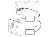
[HMD概観]
図1に示すように、本実施形態に係るHMD1は、ユーザPが頭部に装着した状態で、動画ファイル、静止画ファイル、文章ファイル等の各種コンテンツ情報や後述する仮想操作パネルを画像としてそのユーザPに視認可能に表示するHMD本体2と、そのHMD本体2に対して画像信号を供給する処理を主に行うコントローラ3と、ユーザPの視野範囲の少なくとも一部を撮像するCCD(Charge Coupled Devices)カメラ4と、ユーザPの接触操作を検知するタッチパネル5と、通信可能な制御ボックス150と、を備えている。[HMD overview]
As shown in FIG. 1, the
HMD本体2は、各色(R,G,B)毎に強度変調された光(以下、「画像光」という)をユーザPの網膜上で2次元方向に走査させることにより、ユーザPにコンテンツ情報に対応する画像(以下、単に「コンテンツ」という)を視認させる網膜走査ディスプレイ(Retinal Imaging Display)である。 The HMD
尚、本実施形態においては、HMD本体2として網膜走査ディスプレイを採用したが、これに限らず、例えば、LCD(liquid crystal display)を透過又は反射させて生成した光(画像光)をユーザPの眼Yに投射して、ユーザPにコンテンツを視認させるディスプレイを用いてもよい。 In the present embodiment, the retinal scanning display is adopted as the HMD
このHMD本体2は、コンテンツを表示している最中であっても、ユーザPの視野範囲の中で、そのコンテンツを表示している領域以外の領域では、ユーザPが外界を視認できるように構成している。 The HMD
HMD本体2は、図2に示すように、略眼鏡形状とした支持部材2aと、使用者に認識させるための画像を形成する画像形成部2bとを備えている。画像形成部2bは、ユーザPの眼前にハーフミラー2cを設けており、外光Laはハーフミラー2cを透過させてユーザPの眼Yに入射させ、コンテンツ情報に応じた画像光Lbはハーフミラー2cで反射させてユーザPの眼Yに入射させるようにしている。このようにHMD1は、外光Laを透過しつつ、コンテンツ情報に応じた画像光をユーザPの眼Yに投射するシースルー型のヘッドマウントディスプレイとしている。 As shown in FIG. 2, the HMD
コントローラ3は、HMD本体2、CCDカメラ4、タッチパネル5、制御ボックス150等と通信可能に接続されており、HMD1全体を制御する後述の制御部10(図5参照)等が内蔵されている。 The
CCDカメラ4は、ユーザPの視野範囲のうち少なくとも後述する表示領域6(図3及び図4参照)を撮像する撮像手段201(図7参照)として機能し、ユーザPの視野範囲の画像をサンプリングするように構成されている。 The
このような構成において、HMD1では、図3に示すように、ユーザPの視野範囲のうち少なくとも一部に表示領域6が設定されており、ユーザPは視野範囲内の表示領域6に画像を視認できる。特に、この表示領域6には、仮想操作パネルが表示され、ユーザPの操作に応じた操作が可能となる。また、このHMD1は、シースルー型であるため、外界を視認しつつ、これらの仮想操作パネルが視認可能である。 In such a configuration, in the
尚、本実施形態においては、図3に示すように、仮想操作パネルとして、表示領域6の固定された位置に表示される仮想メニューバー7、ユーザPの手に追随して移動可能な追随仮想キーボード8,9を一例に挙げて説明する。 In the present embodiment, as shown in FIG. 3, as a virtual operation panel, a
タッチパネル5は、ユーザPの指等による接触を検知する。また、このタッチパネル5は、HMD本体2の表示領域6(CCDカメラ4の撮像領域内にある)に配置されることを条件に、その接触操作が有効となる。 The
また、このタッチパネル5は、ユーザPの手を二箇所接触させることによって操作可能である。具体的には、タッチパネル5は、ユーザPの手の基準位置(親指位置)が接触され、更に基準位置とは別の第二の位置が接触されることによって、第二の位置に対応する操作を認識可能とする。 The
ユーザPによる仮想メニューバー7や追随仮想キーボード8,9へのキー操作は、CCDカメラ4で撮像した画像やタッチパネル5からの接触情報に基づいて検知される。 Key operations on the
具体的には、HMD本体2の表示領域6にユーザPの手が入ってくると、CCDカメラ4によってそのユーザPの手が検知される。そして、ユーザPの手の基準位置(親指位置)がタッチパネル5に接触すると、CCDカメラ4によって撮像された画像が解析されてユーザPの手の基準位置が検知され、更にタッチパネル5から接触した接触位置座標が検知される。このように検知された基準位置に応じて、タッチパネル5とCCDカメラ4との位置関係が認識可能となる。即ち、タッチパネル5とHMD本体2の表示領域6との位置関係が認識可能となる。そして、ユーザPの手の基準位置以外の第二の接触が検出されると、タッチパネル5における基準位置との位置関係から、HMD本体2の表示領域6において表示されている仮想操作パネルが操作されたと認識可能となる。 Specifically, when the hand of the user P enters the display area 6 of the HMD
このように、コントローラ3は、CCDカメラ4で撮像した画像や、タッチパネル5からの接触情報に基づいて、ユーザPの指によって操作される位置や、その位置にある仮想操作パネルのキーが操作されたと認識する。 As described above, the
[表示画面]
ここで、本実施形態に係るHMD1における表示画面について、図4を参照して説明する。図4は、本実施形態に係るHMD1の表示画面を示す説明図である。[Display screen]
Here, a display screen in the
図4に示すように、HMD1の表示領域6内には、各種の仮想操作パネル7〜9が表示されている。この表示領域6は、ユーザPの視野範囲のうち少なくとも一部に表示されるように設定されている。また、このHMD1は、シースルー型であるため、外界を視認しつつ、仮想操作パネル7〜9が視認可能である。具体的には、外界にある装置等が視認可能である。 As shown in FIG. 4, various
また、各種の仮想操作パネルには、仮想メニューバー7や、追随仮想キーボード8,9等が含まれている。 The various virtual operation panels include a
仮想メニューバー7には、複数のメニューボタンが設定されており、具体的には、キーボード(K/B)表示キー7a、スクロールキー7b、拡大/縮小キー7cが設定されている。K/B表示キー7aは、ユーザPの手に追随仮想キーボード8,9を表示するためのキーである。スクロールキー7bは、ユーザPの手に追随するスクロールキーを表示するためのキーである。拡大/縮小キー7cは、ユーザPの手に追随する拡大/縮小キーを表示するためのキーである。 In the
このような仮想メニューバー7の操作は、CCDカメラ4で撮像した画像や、タッチパネル5の接触に基づいて行われる。即ち、コントローラ3は、CCDカメラ4で撮像した画像を解析し、更にタッチパネル5による接触位置の検出することによって、ユーザPの手の接触操作を検知する。 Such an operation of the
具体的には、表示領域6にユーザPの手が入ってくると、CCDカメラ4で撮像した画像が解析された結果、ユーザPの手の輪郭や色が検出され、ユーザPの手の位置が検出される。これによって、表示領域6にユーザPの手が入ってきたことが認識可能となり、CCDカメラ4とユーザPの手との位置関係が認識可能となる。 Specifically, when the user P's hand enters the display area 6, the contour and color of the user P's hand are detected as a result of analyzing the image captured by the
また、このようにユーザPの手が検出された場合において、ユーザPの手の基準位置がタッチパネル5に接触すると、そのタッチパネル5からの接触情報に基づいて接触位置座標が検出される。また、画像の解析の結果に基づいて、ユーザPの手の基準位置が検知される。これによって、タッチパネル5とCCDカメラ4との位置関係が認識可能となる。また、上述したようにCCDカメラ4がHMD本体2の表示領域6の少なくとも一部を撮像しているため、タッチパネル5とHMD本体2の表示領域6との位置関係が認識可能となる。 When the user P's hand is detected in this way and the reference position of the user P's hand contacts the
また、ユーザPの手の基準位置とは別に、タッチパネル5に接触した場合には、そのタッチパネル5においてユーザPの手の基準位置との位置関係によって、表示領域6において操作された位置が認識可能となる。 Further, when the
また、追随仮想キーボード8は、コンテンツ(例えば、文書ファイル)の頁を変更するためのスクロールキーボードであり、ユーザPの手に追随して移動可能となっている。 The following
追随仮想キーボード8には、キーボード(K/B)固定追随(固/追)キー8a、キーボード(K/B)非表示キー8b、操作入力キー(前頁キー8c、次頁キー8d)が設定される。K/B固定追随キー8aは、ユーザPの手に追随させずに固定表示させるかユーザPの手に追随して移動させるかを切り替えるためのキーである。K/B非表示キー8bは、キーボードを非表示とするためのキーである。前頁キー8cは、表示させる画面を前頁に変更するためのキーである。次頁キー8dは、表示させる画面を次頁に変更するためのキーである。 The follow
また、追随仮想キーボード9も同じように、K/B固定追随キー9a、K/B非表示キー9bなどが含まれており、それ以外に操作入力キーとしてテンキー9eなどが含まれている。 Similarly, the following
追随仮想キーボード8,9は、K/B固定追随キー8a,9aへの操作により追随設定されているときには、ユーザPの手に追随して移動し、一方、K/B固定追随キー8a,9aへの操作により固定設定されたときには、ユーザPの手が移動しても移動しない。従って、例えば、図5に示すように、追随仮想キーボード8が固定設定され、追随仮想キーボード9が追随設定されているとき、固定設定されている追随仮想キーボード8はユーザPの手に追随して移動しないが、追随設定されている追随仮想キーボード9はユーザPの手に追随して移動することになる。 When the follow
また、このように固定設定も可能とすることにより、複数の追随仮想キーボード8,9を用いることができる。1つの手で操作できる操作キーの数には限界がある。特に追随仮想キーボード8,9では、手の検出誤差による誤操作を防ぐため、操作キーは指に対して大きくせざるを得ず、小さな操作キーを密集させて配置することはできない。そこで、複数の追随仮想キーボード8,9を利用可能とし、必要に応じてそのうち1つを選択して手に追随させれば、より多くの操作を追随仮想キーボード8,9で行うことができる。 In addition, by enabling the fixed setting as described above, a plurality of following
追随仮想キーボード8,9の追随処理は、CCDカメラ4で撮像した画像や、タッチパネル5の接触に基づいて行われる。即ち、コントローラ3は、CCDカメラ4で撮像した画像を解析し、更にタッチパネル5による接触位置の検出することによって、追随するユーザPの手の位置を検知する。 The following processing of the following
具体的には、上述したように表示領域6にユーザPの手が入ってくると、CCDカメラ4で撮像した画像が解析された結果に基づいて、ユーザPの手の位置が検出される。更に画像の解析の結果に基づいて、ユーザPの手の基準位置が検知される。そして、その基準位置を基準として常に一定の位置関係となるよう追随仮想キーボード8、9の表示位置が決定され、表示される。これによって、手や頭が動いて、撮像領域内の基準位置が移動すると、それに合わせて追随仮想キーボード8、9の表示位置が移動するのでその基準位置のある手に追随して追随仮想キーボード8,9が移動することとなる。 Specifically, when the user P's hand enters the display area 6 as described above, the position of the user P's hand is detected based on the analysis result of the image captured by the
また、追随仮想キーボード8,9が追随設定された状態において、ユーザPの手の基準位置がタッチパネル5に接触されると、そのタッチパネル5からの接触情報に基づいて接触位置座標が検出され、タッチパネル5における基準位置の座標が取得される。 Further, in the state where the following
更に、ユーザPの手の基準位置とは異なる位置でタッチパネル5が接触されると、その座標に基づく新たな接触位置と基準位置との関係から、上述したようにタッチパネル5の基準位置とHMD本体2の表示領域6内の基準位置との位置関係に基づいて、その接触位置座標に対応する追随仮想キーボード8,9の操作位置が検出され、その操作に対応する制御が行われることとなる。 Further, when the
このように、コントローラ3は、表示領域6のうち、HMD本体2のハーフミラー2cを透過してユーザPに視認される手と関連し、基準位置と常に所定の位置関係となる位置を、そのユーザPの手の位置に追随する追随仮想キーボード8,9の表示位置として決定して、追随仮想キーボード8,9の画像データに応じた画像信号をHMD本体2に供給する。これにより、追随仮想キーボード8,9は、ユーザPの手に追随して移動する。なお、「ユーザPに視認される手と関連した位置」とは、HMD本体2を介してユーザPに視認されるユーザPの手で追随仮想キーボード8,9が操作できる位置を意味する。 In this way, the
このように、ユーザPの手に追随して追随仮想キーボード8,9が移動することによって、手や頭が動いても追随仮想キーボード8,9の表示位置とユーザPの操作位置とのずれを防止することができる。即ち、操作時にユーザPが自然に頭や手を動かしても、仮想操作パネル8の表示位置がユーザPの手の操作位置に追随していくので、安定した操作入力を行うことができる。 As described above, the tracking
また、コントローラ3は、所定の動作(例えば、K/B固定追随キー8a,9aへの操作など)により、追随仮想キーボード8,9の位置をユーザPの手の位置に追随させずに固定させることができる。従って、不要となった追随仮想キーボード8,9を追随させず、固定させることによって、操作性を向上させることができ、簡便である。 In addition, the
更に、コントローラ3は、所定の動作(例えば、K/B表示キー7aやK/B非表示キー8b,9bへの操作など)に応じて、各追随仮想キーボード8,9の表示を有効とするか無効とするかを決定する。具体的には、コントローラ3は、ユーザPによるK/B表示キー7aへの操作によって有効とされたときに追随仮想キーボード8,9を表示させ、ユーザPによるK/B非表示キー8b,9bへの操作によって無効とされたときに追随仮想キーボード8,9を表示させない。従って、不要となった追随仮想キーボード8,9を非表示とすることによって、視認性を向上させることができ、簡便である。 Further, the
また、複数の追随仮想キーボード8,9からユーザPの手に追随させる追随仮想キーボードを選択するための仮想メニューバー7を表示させる。従って、仮想操作パネルの種類が多種多様となり、簡便である。 Further, the
[HMDの電気的構成]
本実施形態におけるHMD1の電気的構成などについて図5を用いて説明する。[Electrical configuration of HMD]
The electrical configuration of the
図5に示すように、このHMD1は、上述したようなHMD本体2と、そのHMD本体2等を制御するコントローラ3と、CCDカメラ4と、タッチパネル5と、周辺機器34と、制御ボックス150とを備えている。 As shown in FIG. 5, the
コントローラ3は、当該HMD1全体の動作を統括制御する制御部10と、タッチパネルコントローラ20と、CCDカメラコントローラ22と、CCDカメラVRAM24と、HMDインターフェース(図中「I/F」と示し、以下「I/F」ということがある)コントローラ26と、HMD VRAM28と、周辺機器I/F30と、接続I/Fコントローラ32と、を備えている。 The
制御部10は、CPU(Central Processing Unit)12と、不揮発性メモリであるプログラムROM(Read Only Memory)14と、フラッシュROM(フラッシュメモリ)16と、RAM(Random Access Memory)18と、を備えており、これらはデータ通信用のバスにそれぞれ接続されており、このデータ通信用のバスを介して各種情報の送受信を行う。 The
CPU12は、プログラムROM14に記憶されている各種情報処理プログラムを実行することにより、制御部10としてHMD1を構成する各種回路を動作させて、HMD1が備える各種機能を実行させる演算処理装置である。 The CPU 12 is an arithmetic processing unit that executes various information processing programs stored in the program ROM 14 to operate various circuits constituting the
フラッシュROM16は、制御部10がCCDカメラ4により撮像した画像や、制御ボックス150などの他の装置から供給される画像を記憶する。 The
タッチパネルコントローラ20は、制御部10からの制御に基づいて、タッチパネル5からの接触信号を受け取り、その接触信号に基づく接触情報を制御部10に供給する。これによって、制御部10は、タッチパネル5に対するユーザPの各指の動作を認識可能となる。 The touch panel controller 20 receives a contact signal from the
CCDカメラコントローラ22は、CCDカメラ4を制御し、CCDカメラVRAM24は、CCDカメラ4からの画像を一時的に記憶する。制御部10は、ユーザPの手や指の位置を認識するために、CCDカメラコントローラ22を介してCCDカメラ4を制御し、CCDカメラ4によって撮像された画像データをCCDカメラVRAM24から取得する。これによって、制御部10は、CCDカメラ4によって撮像された画像を取得することができ、詳しく後述するが、その画像を解析することによって、ユーザPの手を認識可能となる。 The CCD camera controller 22 controls the
HMD I/Fコントローラ26は、制御部10からの要求に応じてHMD本体2を制御し、制御部10によりHMD VRAM28に記憶された画像データに基づいた画像信号をHMD本体2に供給する。これによって、制御部10は、画像を表示させる制御を行う。 The HMD I / F controller 26 controls the HMD
HMD本体2は、HMD I/Fコントローラ26から画像信号が入力されると、この画像信号に基づいて画像を生成するための要素となる各信号(R,G,Bの3原色の信号)を発生する。また、発生した各信号に基づくレーザ光を出射して合波し、そのレーザ光を2次元に走査する。2次元に走査された光は、その中心線がユーザPの瞳孔に収束するように変換され、ユーザPの眼Yの網膜に投影される。HMD本体2の一般的な構成及び動作については、周知であり(例えば、特開2007−178941号公報参照)、ここでは具体的な説明は省略する。 When an image signal is input from the HMD I / F controller 26, the HMD
周辺機器I/F30は、電源スイッチやランプ類等(図示せず)の周辺機器34をコントローラ3に接続するためのインターフェースである。例えば、電源スイッチやランプ類が周辺機器I/F30に接続されたとき、制御部10は、電源スイッチ等のスイッチ類からの操作情報を周辺機器I/F30から受け取り、周辺機器I/F30を介してランプ類の点灯情報をランプ類に供給する。 The peripheral device I /
接続I/Fコントローラ32は、コントローラ3と制御ボックス150とを通信可能に制御する。制御部10は、接続I/Fコントローラ32を介して画像データの供給を制御ボックス150に要求し、制御ボックス150から接続I/Fコントローラ32を介して供給された画像データをHMD本体2に供給する。また、制御部10は、タッチパネル5からの情報や周辺機器34からの情報を接続I/Fコントローラ32を介して制御ボックス150に供給する。 The connection I /
制御ボックス150は、HMD1の画像表示を主に統括制御する制御部160と、コントローラ3や他の装置との通信を制御する通信I/Fコントローラ170と、を備えている。 The
制御部160は、CPU(Central Processing Unit)162と、不揮発性メモリであるプログラムROM(Read Only Memory)164と、ハードディスク装置(HDD)166と、RAM(Random Access Memory)168と、を備えており、これらはデータ通信用のバスにそれぞれ接続されており、このデータ通信用のバスを介して各種情報の送受信を行う。 The
CPU162は、プログラムROM164に記憶されている各種情報処理プログラムを実行することにより、制御部160として、制御ボックス150を構成する各種回路を動作させて、HMD1が備える各種機能を実行させる演算処理装置である。 The CPU 162 is an arithmetic processing unit that executes various information processing programs stored in the program ROM 164 to operate various circuits constituting the
[サイズテーブル]
上述したような構成のHMD1におけるフラッシュROM16に記憶されているサイズテーブルについて図6を用いて説明する。図6は、サイズテーブルを示す説明図である。[Size table]
A size table stored in the
フラッシュROM16に記憶されたサイズテーブルは、追随仮想キーボード8,9のサイズを決定するためのテーブルである。このサイズテーブルには、図6に示すように、ユーザPの見かけの手のサイズと、追随仮想キーボード8,9の表示サイズとが対応付けられている。 The size table stored in the
例えば、ユーザPの見かけの手のサイズがB(ピクセル)以上A(ピクセル)未満のときには、追随仮想キーボード8,9の表示サイズをXLサイズとし、ユーザPの見かけの手のサイズがD(ピクセル)以上C(ピクセル)未満のときには、追随仮想キーボード8,9の表示サイズをMサイズとする。尚、ここでは、ユーザPの見かけの手のサイズは、ユーザPの親指から各指までの距離によって決定するようにしている。 For example, when the size of the apparent hand of the user P is B (pixels) or more and less than A (pixel), the display size of the following
このようなサイズテーブルの参照によって、ユーザPの見かけの手のサイズに対応した追随仮想キーボード8,9が選択可能となり、ユーザPによる追随仮想キーボード8,9の操作性を向上させることができ、またその操作も容易である。尚、このようなフラッシュROM16は、後述するサイズ情報記憶手段204(図7参照)として機能する。 By referring to such a size table, it becomes possible to select the following
[HMD機能構成]
ここで、本実施形態に係るHMD1の機能構成等について、図7を参照して説明する。図7は、本実施形態に係るHMD1の機能構成を示す説明図である。[HMD function configuration]
Here, a functional configuration and the like of the
図7に示すように、このHMD1におけるCCDカメラ4は、ユーザPの視野範囲を撮像して画像データを生成し、制御部10にその画像データを供給する撮像手段201として機能する。 As shown in FIG. 7, the
また、このHMD1におけるHMD本体2は、表示手段210として機能する。この表示手段210は、外光Laを透過しつつ、画像情報(表示情報)に応じた画像光をユーザPの眼Yに投射してそのユーザPに画像光に応じた画像を視認させる。 Further, the HMD
HMD1における制御部10は、後述のCPU12が所定の情報処理プログラムを実行することによって、画像解析手段202、手検知手段203、仮想操作パネルサイズ選択手段205、仮想操作パネル位置決定手段206、表示決定手段207、選択用仮想操作パネル位置設定手段208、表示制御手段209、焦点設定手段211、操作判定手段213、操作対応制御手段214として機能することとなる。 The
画像解析手段202は、撮像手段201によって撮像された画像データを解析する。特に、画像解析手段202は、撮像手段201から出力される画像データを解析して、撮像手段201によって撮像された画像の輪郭検出、色検出などを行う。 The
手検知手段203は、画像解析手段202によって解析された結果に基づいて、ユーザPの手を検知する。特に、この手検知手段203は、ユーザPの手の位置に加えて、ユーザPの手のサイズを検知する。 The
サイズ情報記憶手段204は、上述したフラッシュROM16が相当する。このサイズ情報記憶手段204には、ユーザPの手のサイズと、そのユーザPの手のサイズに応じて追随仮想キーボード8,9のサイズが対応付けられたサイズ情報であるサイズテーブル(図6参照)が記憶されている。 The size
仮想操作パネルサイズ選択手段205は、手検知手段203によって検出されたユーザPの手のサイズと、サイズ情報記憶手段204に記憶されたサイズ情報とに基づいて、そのユーザPの手のサイズに対応して追随仮想キーボード8,9のサイズを選択する。 The virtual operation panel
仮想操作パネル位置決定手段206は、手検知手段203によって検知されたユーザPの手の位置に基づいて、表示手段210による表示領域のうち、表示手段210を透過してユーザPに視認される手と関連した位置を、そのユーザPの手の位置に追随する追随仮想キーボード8,9の表示位置として決定する。即ち、仮想操作パネル位置決定手段206は、ユーザPに視認される追随仮想キーボード8,9がHMD本体2を介してユーザPに視認されるユーザPの手で操作できる位置を追随仮想キーボード8,9の表示位置として決定する。 Based on the position of the user P's hand detected by the
特に、ユーザPのサイズに応じて、ユーザPが操作し易い追随仮想キーボード8,9のサイズも異なり、それに伴い追随仮想キーボード8,9の表示位置も適切に配置する必要があることから、仮想操作パネル位置決定手段206は、仮想操作パネルサイズ選択手段205によって選択された追随仮想キーボード8,9のサイズに基づいて、追随仮想キーボード8,9の表示位置を決定する。 In particular, depending on the size of the user P, the size of the following
また、仮想操作パネル位置決定手段206は、所定の動作(例えば、ユーザPによるK/B固定追随キー8a,9aの操作など)に応じて、追随仮想キーボード8,9の位置をユーザPの手の位置に追随させずに固定させる。例えば、ユーザPによりK/B固定追随キー8a,9aが操作されて、追随仮想キーボード8,9が固定設定されているとき、仮想操作パネル位置決定手段206は、制御ボックス150に対して、追随仮想キーボード8,9の位置を変更した画像データを要求しない。 Further, the virtual operation panel position determining means 206 determines the positions of the following
また、仮想操作パネル位置決定手段206は、重複する位置に複数の仮想操作パネル(例えば、仮想メニューバー7や追随仮想キーボード8,9などを含む)が設定されている場合には、その重複する複数の追随仮想キーボード8,9のうち、ユーザPの手の位置に追随すると最新に選択された追随仮想キーボードを優先して、追随移動させる決定を行う。 Further, the virtual operation panel
表示決定手段207は、所定の動作(例えば、ユーザPによるK/B表示キー7aやK/B非表示キー8b,9bへの操作など)に応じて、追随仮想キーボード8,9の表示を有効とするか無効とするかを決定する。ここで、追随仮想キーボード8,9の表示を有効にするとは、追随仮想キーボード8,9を表示領域6に表示することであり、追随仮想キーボード8,9の表示を無効にするとは、追随仮想キーボード8,9を表示領域6に表示しないことである。 The display determination means 207 enables the display of the following
選択用仮想操作パネル位置設定手段208は、複数の仮想操作パネルからユーザPの手に追随させる追随仮想キーボード8,9を選択するための仮想メニューバー7(選択用仮想操作パネル)を表示領域6内の所定の表示位置(例えば、左側方など)に設定する。 The selection virtual operation panel position setting means 208 displays a virtual menu bar 7 (selection virtual operation panel) for selecting the following
表示制御手段209は、仮想操作パネル位置決定手段206により決定した表示位置に仮想操作パネル(仮想メニューバー7や追随仮想キーボード8,9)を表示手段210により表示させる制御を行う。また、表示制御手段209は、表示決定手段207によって有効に設定された追随仮想キーボード8,9を表示手段210により表示させる制御を行い、表示決定手段207によって無効に設定された追随仮想キーボード8,9を表示手段210により表示させない制御を行う。 The
焦点設定手段211は、表示決定手段207によって追随仮想キーボード8,9を有効に設定された場合には、撮像手段201による焦点距離を特定の焦点距離に設定する。尚、特定の焦点距離はユーザPの手が存在する標準的な距離として予めフラッシュROM16に記憶されているが、ユーザPによる操作で距離を設定することもできる。 The
タッチパネル5は、ユーザPの手の接触を検知し、ユーザPの指による動作を検知する。 The
操作判定手段213は、タッチパネル5によって検知された指の接触位置に基づいて、仮想操作パネルが操作されたか否かを判定する。 The
即ち、操作判定手段213は、タッチパネル5から出力される接触信号に基づいて、ユーザPが操作された位置座標を判定する。更に、操作判定手段213は、その操作された位置座標が、仮想操作パネル(仮想メニューバー7や追随仮想キーボード8,9)上のキーの座標と一致するか否かによって、仮想操作パネルが操作されたか否かを判定する。このとき、基準位置に対する相対座標、あるいは基準位置を原点として操作された位置座標を判定すればよい。例えば、操作された位置座標が、追随仮想キーボード8,9上のK/B非表示キー8bの座標と一致するとき、K/B非表示キー8bが操作されたと判定することになる。 That is, the
操作対応制御手段214は、操作判定手段213によって仮想操作パネルが操作されたと判定された場合には、その仮想操作パネルへの操作位置に対応する制御を行う。 If the
例えば、仮想メニューバー7の表示キー7aが操作されたとき、表示領域6に追随仮想キーボード8,9を表示する制御を行い、追随仮想キーボード8,9の非表示キー8b,9bが操作されたとき、表示領域6から追随仮想キーボード8,9を消去する制御を行う。また、追随仮想キーボード8,9が追随設定されているときには、ユーザPの手の位置に応じて表示領域6内で、追随設定されている追随仮想キーボード8,9を移動させる制御を行う。 For example, when the display key 7a of the
本実施形態においては、追随仮想キーボード8,9の表示、移動、消去は、制御ボックス150へ要求を行うことによって行われる。即ち、操作対応制御手段214は、追随仮想キーボード8,9を表示した画像データ、追随仮想キーボード8,9の表示位置を移動した画像データ、追随仮想キーボード8,9を消去した画像データを制御ボックス150に要求し、この要求に応じて制御ボックス150から取得した画像データをHMD本体2で表示させる。追随仮想キーボード8,9の表示又は移動するとき、制御ボックス150は、追随仮想キーボード8,9を表示又は移動した画像をコンテンツの画像に合成した画像データをコントローラ3に送信する。尚、追随仮想キーボード8,9の画像は、コントローラ3内で制御ボックス150から取得した画像と合成するようにしてもよい。 In the present embodiment, the following
[制御動作]
次に、図8から図13のフローチャートを参照して、HMD1の動作について説明する。図8から図13は、HMD1において実行される処理の動作を示すフローチャートである。特に、図8に示すメイン処理は、HMD1の電源がオンされた際に、コントローラ3における制御部10によって実行され、その実行によってコントローラ3の制御部10が上記各手段として機能する。また、図12に示すメイン処理は、制御ボックス150の所定のアプリケーション起動操作が行われてから制御部160によって実行され、その実行によって制御ボックス150の制御部160が上記各手段として機能する。尚、以下の説明においては、追随仮想キーボード8,9を代表して追随仮想キーボード8について主に説明する。[Control action]
Next, the operation of the
[メイン処理]
最初に、図8に示すように、HMD1に電源が投入されると、制御部10は、初期設定を行う(ステップS10)。この処理において、制御部10は、RAMアクセス許可、作業領域の初期化等を実行する。この処理が終了した場合には、ステップS11に処理を移す。[Main processing]
First, as shown in FIG. 8, when the
ステップS11において、制御部10は、制御ボックス150に画像データの要求を行う。そして、制御部10は、制御ボックス150から画像データの入力があるか否かを判定する(ステップS12)。 In step S <b> 11, the
制御部10は、制御ボックス150から画像データの入力があると判定すると(ステップS12:YES)、ステップS13に処理を移す。 If the
一方、制御部10は、制御ボックス150から画像データの入力がないと判定すると(ステップS12:NO)、再度ステップS12に処理を移し、映像入力があるまでステップS12を繰り返し行うこととなる。 On the other hand, when determining that there is no input of image data from the control box 150 (step S12: NO), the
ステップS13において、制御部10は、制御ボックス150から入力された画像データを画像信号としてHMD本体2に出力する。制御ボックス150から入力される画像データは、初期設定されているコンテンツの最初の頁の画像と仮想メニューバー7の画像とが含まれる画像データである。これによって、HMD本体2は、最初の頁の画像と仮想メニューバー7の画像とを含む画像をユーザPに視認可能に表示する。この処理が終了した場合には、ステップS14に処理を移す。尚、本実施形態において、このような処理を実行する制御部10は、選択用仮想操作パネル位置設定手段208、表示制御手段209として機能する。 In step S13, the
ステップS14において、制御部10は、新たな画像データの入力が制御ボックス150からあり、その画像データに基づく画像信号を出力するか否かを判定する。 In step S <b> 14, the
制御部10は、新たな画像データが制御ボックス150からあり、その画像データに基づく画像信号を出力すると判定すると(ステップS14:YES)、制御ボックス150から入力された画像データを画像信号としてHMD本体2に出力し(ステップS15)、ステップS16に処理を移す。 If the
一方、制御部10は、新たな画像データが制御ボックス150からなく、その画像データに基づく画像信号を出力しないと判定すると(ステップS14:NO)、ステップS15を実行することなく、ステップS16に処理を移す。 On the other hand, if the
ステップS16において、制御部10は、カメラ画像が入力されたか否かを判定する。この処理において、制御部10は、CDDカメラ4からの画像データが記憶されるCCDカメラVRAM24から画像データを読み出し、画像データが更新されているか否かによって、カメラ画像入力されたか否かを判定する。 In step S <b> 16, the
制御部10は、カメラ画像が入力されたと判定すると(ステップS16:YES)、詳しく図9から図11を用いて後述するが、CCDカメラ4から入力された画像に基づく解析や、その解析結果に基づく制御等を行うカメラ受信画像処理を実行し(ステップS17)、ステップS18に処理を移す。 If the
一方、制御部10は、カメラ画像が入力されていないと判定すると(ステップS16:NO)、ステップS17を実行することなく、ステップS18に処理を移す。 On the other hand, when the
ステップS18において、制御部10は、ユーザPによって追随仮想キーボード8の表示、移動、操作、消去などのアクションがあるか否かを判定する。例えば、制御部10は、後述するステップS42、ステップS63において追随仮想キーボード8の表示設定が行われたときに「表示」のアクションがあったと判定する。また、制御部10は、後述するステップS46、ステップS63で追随仮想キーボード8の移動設定が行われたときに「移動」のアクションがあったと判定する。また、制御部10は、後述するステップS64でキー入力出力が設定されたとき「操作」のアクションがあったと判定する。また、制御部10は、後述するステップS36で追随仮想キーボード8の消去が設定されたとき「消去」のアクションがあったと判定する。また、制御部10は、後述するステップS64、ステップS72で操作入力キーの出力設定がされたとき「操作入力キーの操作」があったと判定する。 In step S <b> 18, the
制御部10は、アクションがあったと判定すると(ステップS18:YES)、ステップS19に処理を移す。一方、制御部10は、アクションがなかったと判定すると(ステップS18:NO)、再度、ステップS14に処理を移す。 When determining that there is an action (step S18: YES), the
ステップS19において、制御部10は、画像判断出力処理を実行する。この処理において、制御部10は、追随仮想キーボード8の表示、移動、操作、消去、固定などのアクションの内容を示す画像判断を制御ボックス150に出力する。この画像判断は、追随仮想キーボード8の表示はK/B表示要求として、追随仮想キーボード8の移動はK/B表示位置移動要求として、追随仮想キーボード8の消去はK/B表示消去要求として、追随仮想キーボード8の操作はキーボード操作情報として、制御ボックス150に出力される。この処理が終了した場合には、ステップS20に処理を移す。 In step S19, the
ステップS20において、制御部10は、電源オフであるか否かを判定する。この処理において、制御部10は、電源スイッチの操作等に応じて、電源オフであるか否かを判定することとなる。制御部10は、電源オフであると判定すると(ステップS20:YES)、メイン処理を終了する。一方、制御部10は、電源オフではないと判定すると(ステップS20:NO)、再度、ステップS14に処理を移す。これによって、制御部10は、電源オフとなるまで、ステップS14からステップS20を繰り返し実行することとなる。 In step S20, the
[カメラ受信画像処理]
図8のステップS17において実行されるサブルーチンについて図9から図11を用いて説明する。[Camera received image processing]
The subroutine executed in step S17 in FIG. 8 will be described with reference to FIGS.
最初に、図9に示すように、制御部10は、CCDカメラVRAM24から画像データを読み出す(ステップS31)。そして、制御部10は、以前の画像データと同じであるか否かを比較し、その結果、画像データに変化があるか否かを判定する(ステップS32)。この処理において、制御部10は、画像データに変化があると判定すると(ステップS32:YES)、ステップS33に処理を移す。一方、制御部10は、画像データに変化がないと判定すると(ステップS32:NO)、図10のステップS51に処理を移す。 First, as shown in FIG. 9, the
ステップS33において、制御部10は、変化した画像データの輪郭検出、色検出を行う。つまり、制御部10は、CCDカメラ4による撮像領域にある画像を解析することとなる。 In step S33, the
そして、制御部10は、この輪郭検出、色検出の結果に基づいて、ユーザPの手の輪郭を検知する処理を行う。例えば、制御部10は、肌色の部分のみを抽出して、その外形から画像処理を行い、輪郭を検出する。そして、制御部10は、画面内にユーザPの手があるか否かを判定する(ステップS34)。例えば、制御部10は、検出した輪郭が所定範囲の大きさであり、その輪郭の形状が所定の形状(代表的な手の形状が予め登録されている)との相関性が高い、あるいは下方部に対して上方部が複数に枝分かれしているような形状となっているかを判断することでユーザPの手があると判定できる。この処理において、制御部10は、表示領域6内にユーザPの手があると判定すると(ステップS34:YES)、ステップS37に処理を移す。一方、制御部10は、表示領域6内にユーザPの手がないと判定すると(ステップS34:NO)、ステップS35に処理を移す。 And the
ステップS35において、制御部10は、HMD本体2の表示領域6内に追随設定された追随仮想キーボード8があるか否かを判定する。この処理において、制御部10は、HMD本体2の表示領域6内に追随設定された追随仮想キーボード8があると判定した場合には(ステップS35:YES)、ユーザPの手が撮像範囲内になく、追随設定された追随仮想キーボード8が表示されているため、追随キーボードを消去し(ステップS36)、本サブルーチンを終了する。 In step S <b> 35, the
一方、制御部10は、HMD本体2の表示領域6内に追随設定された追随仮想キーボード8がないと判定した場合には(ステップS35:NO)、ユーザPの手が撮像範囲内になく、追随設定された追随仮想キーボード8が表示されていないため、ステップS36を実行することなく、本サブルーチンを終了する。 On the other hand, when the
このように、制御部10は、ユーザPの手がCCDカメラ4の撮像範囲内にない場合には、追随仮想キーボード8を消去することとなる。 As described above, the
一方、ステップS37において、制御部10は、HMD本体2の表示領域6内に追随仮想キーボード8があるか否かを判定する。この処理においては、固定設定されているか追随設定されているかに拘わらず、HMD本体2の表示領域6内に追随仮想キーボード8があるか否かが判定される。 On the other hand, in step S <b> 37, the
この処理において、制御部10は、HMD本体2の表示領域6内に追随仮想キーボード8があると判定した場合には(ステップS37:YES)、ステップS43に処理を移す。一方、制御部10は、HMD本体2の表示領域6内に追随仮想キーボード8がないと判定した場合には(ステップS37:NO)、ステップS38に処理を移す。 In this process, if the
ステップS38において、制御部10は、基準座標判定処理を実行する。この処理において、制御部10は、CCDカメラ4から出力される画像データを解析した結果に基づいて、ユーザPの手における親指の位置を基準座標として判定し、その判定したユーザPの基準座標(親指位置)を取得する(ステップS39)。例えば、制御部10は、検出したユーザPの手の輪郭の上方部において、4つの枝分かれより下方で左右のどちらかにある枝分かれを親指と判断する。そして、制御部10は、その親指位置における先端の座標を基準座標として取得する。この親指位置を基準座標とすることにより親指はタッチパネル5に接触したままに固定されるので、キー操作を行うためにユーザPが他の指を動かしても、これらの指の動きには仮想パネルの表示位置が追随せず、安定した確実な操作を行うことができる。尚、親指が左右どちらかにあるかも検出されるので、キーは他の指がある側に表示される。もちろん。小指などの他の指を基準座標としてもよい。 In step S38, the
特に、本実施形態において、制御部10は、撮像された画像解析の結果に基づいて、ユーザPの手を検知し、かつ、ユーザPの親指を追随の基準位置として決定することとなる。 In particular, in the present embodiment, the
そして、制御部10は、その基準座標から各指までの距離を取得し(ステップS40)、更に、各指の先端座標を取得する(ステップS41)。即ち、制御部10は、検出した輪郭の上方部の枝分かれ部分の各先端を各指の先端と判断し、基準座標からの距離や座標を取得することができる。これによって、制御部10は、CCDカメラ4から出力される画像データを解析した結果に基づいて、ユーザPの手を検知し、ユーザPの手の位置に加えて、ユーザPの手のサイズを検知する。例えば、制御部10は、基準座標から各指までの距離のうち最大のものをユーザPの見かけの手のサイズとしてもよい。また、制御部10は、親指以外の指先の座標から最も離れた2つの座標の距離をユーザPの見かけの手のサイズとしてもよい。このとき、制御部10は、親指から、最も近い指までの距離も検出できるので、基準位置からこの距離だけ離れた位置にユーザPの見かけの手のサイズに応じたサイズの追随仮想キーボード8を表示すればよい。 And the
そして、制御部10は、サイズテーブル(図6参照)を参照し、ユーザPの手のサイズに基づいて、追随仮想キーボード8のサイズを決定する(ステップS42)。そして、制御部10は、ユーザPの手に追随する追随仮想キーボード8の表示設定を行う。制御部10は、図4に示すように、ユーザPの親指位置を基準位置とし、ユーザPの手の輪郭のうち、手首から最も遠い指先と手首までの範囲のうちの親指の先端を通る水平線から上の領域、即ち指のある領域に表示するのが望ましい。また、4つの指の根元、即ち輪郭が枝分かれする根元部分より上側に表示するようにしてもよい。 Then, the
そして、制御部10は、表示設定の結果、上述したステップ19において、K/B表示要求を制御ボックス150に出力する。このK/B表示要求は、追随仮想キーボード8のサイズや、ユーザPの親指の位置に対応する追随仮想キーボード8の座標位置などを含む。これによって、制御ボックス150において、追随仮想キーボード8を表示させる画像データが生成され、コントローラ3に出力される。 Then, as a result of the display setting, the
つまり、制御部10は、ステップS41において検出されたユーザPの手のサイズと、フラッシュROM16に記憶されたサイズテーブルとに基づいて、そのユーザPの手のサイズに対応して追随仮想キーボード8のサイズを選択することとなる。 That is, based on the size of the user P's hand detected in step S41 and the size table stored in the
また、制御部10は、追随設定がされている追随仮想キーボード8を最上位に表示させ、優先して操作を検知することとなる。つまり、制御部10は、重複する位置に複数の仮想操作パネル(仮想メニューバー7や追随仮想キーボード8,9)が設定されている場合には、それら重複する複数の仮想操作パネルのうち、ユーザPの手の位置に追随すると最新に選択された追随仮想キーボードを優先して設定することとなる。この処理が終了した場合には、本サブルーチンを終了する。 In addition, the
一方、ステップS43において、制御部10は、追随設定された追随仮想キーボード8があるか否かを判定する。この処理において、制御部10は、追随設定された追随仮想キーボード8があると判定した場合には(ステップS43:YES)、ステップS44に処理を移す。一方、制御部10は、追随設定された追随仮想キーボード8がないと判定した場合には(ステップS43:NO)、ステップS44からステップS46を実行することなく、本サブルーチンを終了する。 On the other hand, in step S43, the
ステップS44において、制御部10は、CCDカメラ4から出力される画像データを解析した結果に基づいて、ユーザPの手における親指の位置を基準座標として判定し、その判定したユーザPの基準座標(親指位置)を取得する(ステップS45)。このように、制御部10は、CCDカメラ4から出力される画像データを解析した結果に基づいて、ユーザPの手を検知し、ユーザPの手の位置を検知する。 In step S44, the
そして、制御部10は、基準座標に基づき追随仮想キーボード8の追随移動の設定を行う(ステップS46)。そして、制御部10は、追随移動設定の結果、上述したステップ19において、K/B表示位置移動要求を制御ボックス150に出力する。このK/B表示位置移動要求は、ユーザPの親指の位置に対応する追随仮想キーボード8の座標位置などを含む。これによって、制御ボックス150において、追随仮想キーボード8をユーザPの手に追随表示させる画像データが生成され、コントローラ3に出力される。 Then, the
また、制御部10は、追随設定がされている追随仮想キーボード8を最上位に表示させ、優先して操作を検知することとなる。つまり、制御部10は、重複する位置に複数の仮想操作パネル(仮想メニューバー7や追随仮想キーボード8,9)が設定されている場合には、それら重複する複数の仮想操作パネルのうち、ユーザPの手の位置に追随すると最新に選択された追随仮想キーボードを優先して設定することとなる。この処理が終了した場合には、本サブルーチンを終了する。 In addition, the
図10のステップS51において、制御部10は、タッチパネル5によって検知されたユーザPの指の接触位置情報が出力されたか否かを判定する。この処理において、制御部10は、最初に接触された接触状態が保たれているユーザPの手の基準位置とは異なる接触位置が検知されることによって、タッチパネル5によって検知されたユーザPの指の接触位置情報が出力されたと判定することとなる。 In step S <b> 51 of FIG. 10, the
尚、制御部10は、追随仮想キーボードを操作する場合には、タッチパネル5によって最初に一箇所(ひとつのまとまり)の接触位置座標を検知したときに、この接触位置座標を親指の位置として検知し、その最初の接触状態が保たれている状態において二箇所目(ひとつのまとまり)の接触位置座標を検知した場合には、その接触位置座標に対応する位置が操作されたと認識することとなる。 In addition, when operating the following virtual keyboard, the
つまり、制御部10は、基準位置となるユーザの手の親指(特定部分)とは異なる第2の特定部分(例えば人差し指など)がタッチパネル5に接触した位置に基づいて、追随仮想キーボード8が操作されたか否かを判定することとなる。 That is, the
制御部10は、タッチパネル5によって検知されたユーザPの指の接触位置情報が出力されたと判定すると(ステップS51:YES)、ステップS52に処理を移す。一方、制御部10は、タッチパネル5によって検知されたユーザPの指の接触位置情報が出力されていないと判定すると(ステップS51:NO)、本サブルーチンを終了する。 If it determines with the
そして、制御部10は、上述した輪郭検出、色検出の結果に基づいて、ユーザPの手の輪郭を検知し、表示領域6(画面)内にユーザPの手があるか否かを判定する(ステップS52)。この処理において、制御部10は、表示領域6内にユーザPの手があると判定すると(ステップS52:YES)、ステップS53に処理を移す。一方、制御部10は、表示領域6内にユーザPの手がないと判定すると(ステップS52:NO)、本サブルーチンを終了する。 And the
一方、ステップS53において、制御部10は、タッチパネル5によって検知されたユーザPの指の接触位置座標(接触位置情報)を取得する。そして、制御部10は、ユーザPの手の基準位置となる基準座標に基づいて、タッチ位置座標を取得する(ステップS54)。この処理において、制御部10は、ユーザPの手の基準位置と、取得した接触位置座標との位置関係から、接触位置座標に対応するタッチ位置座標を取得する。このタッチ位置座標は、HMD本体2における表示領域6における座標であり、どの位置が操作されたか否かが認識可能となる。 On the other hand, in step S <b> 53, the
そして、制御部10は、HMD本体2の表示領域6内に追随設定された追随仮想キーボード8があるか否かを判定する(ステップS56)。この処理において、制御部10は、HMD本体2の表示領域6内に追随設定された追随仮想キーボード8があると判定した場合には(ステップS56:YES)、図11のステップS71に処理を移す。一方、制御部10は、HMD本体2の表示領域6内に追随設定された追随仮想キーボード8がないと判定した場合には(ステップS56:NO)、ステップS57に処理を移す。 Then, the
ステップS57において、制御部10は、撮像したユーザPの指の接触位置座標が仮想メニューバー7のK/B表示キー7aの位置座標と一致するか否かを判定する。この処理において、制御部10は、タッチパネル5によるユーザPの指の接触位置座標に基づいて、仮想メニューバー7が操作されたか否かを判定する。この仮想メニューバー7は、複数の追随仮想キーボード8からユーザPの手に追随させる追随仮想キーボードを選択するための選択用仮想操作パネルである。尚、ユーザPがK/B表示キー7aを操作するたびに、追随仮想キーボード8が増加することになる。尚、仮想メニューバー7は、仮想操作パネルのキーより十分大きく表示されており、仮想操作パネルの種類を選択する最初の操作を行うためだけなので、細かなキー操作を行う必要がなく、表示画面内に固定されていても操作性は損なわれない。また、この仮想メニューバー7は、追随しないので、タッチパネル5は単に接触したかどうかだけ検出すればよい。 In step S <b> 57, the
この処理において、制御部10は、タッチパネル5によるユーザPの指の接触位置座標が仮想メニューバー7のK/B表示キー7aの位置座標と一致すると判定すると(ステップS57:YES)、CCDカメラ4の焦点距離をユーザPの手が存在する標準的な距離に設定し、ステップS59に処理を移す。一方、制御部10は、撮像したユーザPの指の位置座標が仮想メニューバー7のK/B表示キー7aの位置座標と一致しないと判定すると(ステップS57:NO)、ステップS58に処理を移す。 In this process, when the
ステップS58において、制御部10は、撮像されたユーザPの手の位置座標が、固定設定されている追随仮想キーボード8の位置座標に近いか否かを判定する。つまり、制御部10は、追随仮想キーボード8の位置が固定されている場合において、CCDカメラ4から出力される画像データを解析した結果に基づいて、ユーザPの手の位置がその追随仮想キーボード8の位置まで所定距離以内となったときには、追随仮想キーボード8の位置を、そのユーザPの手の位置に追随する追随仮想キーボード8の表示位置として決定してもよい。このようにすることで、追随させる追随仮想キーボードの選択が容易となり、簡便である。 In step S58, the
制御部10は、撮像されたユーザPの手の座標が、固定設定されている追随仮想キーボード8の位置座標と近いと判定すると(ステップS58:YES)、CCDカメラ4の焦点距離をユーザPの手が存在する標準的な距離に設定し、ステップS59に処理を移す。一方、制御部10は、撮像されたユーザPの手の座標が、固定設定されている追随仮想キーボード8の位置座標と近くないと判定すると(ステップS58:NO)、本サブルーチンを終了する。 When the
ステップS59において、制御部10は、CCDカメラ4から出力される画像データを解析した結果に基づいて、ユーザPの手における親指の位置を基準座標として判定し、その判定したユーザPの基準座標(親指位置)を取得する(ステップS60)。 In step S59, the
尚、制御部10は、HMD本体2の表示領域6内に追随設定された追随仮想キーボード8がある場合において、タッチパネル5によって三箇所(三つのまとまり)以上の接触位置座標を検知したときには、この親指以外の動作したユーザPの指の操作を検知せず、タッチパネル5によって二箇所(二つのまとまり)の接触位置座標を検知したときには、親指と、この親指以外の動作したユーザPの指の操作を検知することとなる。 In addition, when there is a tracking
そして、制御部10は、その基準座標から各指までの距離を取得し(ステップS61)、更に、各指の先端座標を取得する(ステップS62)。これによって、制御部10は、
CCDカメラ4から出力される画像データを解析した結果に基づいて、ユーザPの手を検知し、ユーザPの手の位置に加えて、ユーザPの手のサイズを検知する。Then, the
Based on the result of analyzing the image data output from the
そして、制御部10は、サイズテーブル(図6参照)を参照し、ユーザPの手のサイズに基づいて、追随仮想キーボード8のサイズを決定する(ステップS62)。そして、制御部10は、ユーザPの手に追随する追随仮想キーボード8の表示設定を行う(ステップS63)。制御部10は、追随仮想キーボード8が表示されていないときには追随仮想キーボード8の表示を設定し、固定設定された追随仮想キーボード8が表示されるときには追随仮想キーボード8の移動を設定する。 Then, the
そして、制御部10は、表示設定の結果、上述したステップ19において、K/B表示要求を制御ボックス150に出力する。このK/B表示要求は、追随仮想キーボード8のサイズや、ユーザPの親指の位置に対応する追随仮想キーボード8の座標位置などを含む。これによって、制御ボックス150において、追随仮想キーボード8を表示させる画像データが生成され、コントローラ3に出力される。 Then, as a result of the display setting, the
つまり、制御部10は、ステップS62において検出されたユーザPの手のサイズと、フラッシュROM16に記憶されたサイズテーブルとに基づいて、そのユーザPの手のサイズに対応して追随仮想キーボード8のサイズを選択することとなる。 That is, based on the size of the user P's hand detected in step S <b> 62 and the size table stored in the
また、制御部10は、K/B表示キー7aが1回操作された場合には、前頁キー8c、次頁キー8dが含まれる追随仮想キーボード8を表示させ、K/B表示キー7aが2回操作された場合には、テンキー9eが含まれる追随仮想キーボード9を表示させるようにしてもよい。 Further, when the K / B display key 7a is operated once, the
また、制御部10は、追随設定がされている追随仮想キーボード8を最上位に表示させ、優先して操作を検知することとなる。つまり、制御部10は、重複する位置に複数の仮想操作パネル(仮想メニューバー7や追随仮想キーボード8,9)が設定されている場合には、それら重複する複数の仮想操作パネルのうち、ユーザPの手の位置に追随すると最新に選択された追随仮想キーボードを優先して設定することとなる。この処理が終了した場合には、本サブルーチンを終了する。 In addition, the
図11のステップS71において、制御部10は、タッチパネル5によるユーザPの指の接触位置座標に基づいて、追随設定された追随仮想キーボード8の操作入力キー(例えば、前頁キー8c、次頁キー8dなど)が選択されたか否かを判定する。 In step S71 of FIG. 11, the
尚、制御部10は、HMD本体2の表示領域6内に追随設定された追随仮想キーボード8がある場合において、タッチパネル5によって三箇所(三つのまとまり)以上の接触位置座標を検知したときには、この親指以外の動作したユーザPの指の操作を検知せず、タッチパネル5によって二箇所(二つのまとまり)の接触位置座標を検知したときには、親指と、この親指以外の動作したユーザPの指の操作を検知することとなる。 In addition, when there is a tracking
制御部10は、操作入力キーが選択されたと判定されると(ステップS71:YES)、その操作入力キーを制御ボックス150に出力する設定を行い(ステップS72)、本サブルーチンを終了する。一方、制御部10は、操作入力キーが選択されていないと判定されると(ステップS71:NO)、ステップS73に処理を移す。 If it is determined that the operation input key has been selected (step S71: YES), the
ステップS73においては、制御部10は、タッチパネル5によるユーザPの指の接触位置座標に基づいて、追随可能な追随仮想キーボード8のうち、K/B非表示キー8bが選択されたか否かを判定する。制御部10は、K/B非表示キー8bが選択されたと判定されると(ステップS73:YES)、その選択されたK/B非表示キー8bがある追随仮想キーボード8を消去する設定を行う(ステップS74)。 In step S <b> 73, the
そして、制御部10は、消去設定の結果、上述したステップ19において、K/B表示消去要求を制御ボックス150に出力する。このK/B表示消去要求は、追随仮想キーボード8の表示を消去させる旨の情報などを含む。これによって、制御ボックス150において、追随仮想キーボード8の表示を消去させた画像データが生成され、コントローラ3に出力される。この処理が終了した場合には、本サブルーチンを終了する。 Then, as a result of the erasure setting, the
一方、制御部10は、K/B非表示キー8bが選択されていないと判定されると(ステップS73:NO)、ステップS75に処理を移す。 On the other hand, when it is determined that the K / B non-display key 8b is not selected (step S73: NO), the
ステップS75においては、制御部10は、タッチパネル5によるユーザPの指の接触位置座標に基づいて、追随可能な追随仮想キーボード8のうち、K/B固定追随キー8aが選択されたか否かを判定する。制御部10は、K/B固定追随キー8aが選択されたと判定されると(ステップS75:YES)、今現在のユーザPの手の基準座標に基づいて、その選択されたK/B固定追随キー8aがある追随仮想キーボード8を固定させる設定を行い(ステップS76)、本サブルーチンを終了する。一方、制御部10は、K/B固定追随キー8aが選択されていないと判定されると(ステップS75:NO)、本サブルーチンを終了する。 In step S75, the
このように、ユーザPの手に追随して追随仮想キーボード8が移動することによって、追随仮想キーボード8の表示位置とユーザPの操作位置とのずれを防止することができる。これによりユーザPに対し、操作中に頭や手の固定を強いることなく、操作中の自然な頭や手の動きを許容し、かつ安定した、確実な操作を行うことができる。 Thus, the follow
また、ユーザPによるK/B固定追随キー8aへの操作といった所定の動作に応じて、追随仮想キーボード8の位置をユーザPの手の位置に追随させずに固定させることができるので、不要となった追随仮想キーボード8を追随させず、固定させることによって、操作性を向上させることができ、簡便である。 Further, since the position of the tracking
また、ユーザPによるK/B非表示キー8bへの操作といった所定の動作に応じて、追随仮想キーボード8の表示を有効とするか無効とするかを決定し、有効に設定された追随仮想キーボード8を表示させ、無効に設定された追随仮想キーボード8を表示させない。従って、不要となった追随仮想キーボード8を非表示とすることによって、視認性を向上させることができ、簡便である。 Further, in accordance with a predetermined operation such as an operation to the K / B non-display key 8b by the user P, it is determined whether the display of the tracking
[アプリケーション]
制御ボックス150において実行されるアプリケーションについて図12及び図13を用いて説明する。[application]
An application executed in the
最初に、図12に示すように、制御ボックス150の制御部160は、初期設定を行う(ステップS101)。この処理において、制御部160は、RAMアクセス許可、作業領域の初期化等を実行する。この処理が終了した場合には、ステップS102に処理を移す。 First, as shown in FIG. 12, the
ステップS102において、制御部160は、通信I/Fコントローラ170を介して、コントローラ3から信号入力があるか否かを判定する。この処理において、制御部160は、画像の要求を示す信号や、アクションを示す信号などの信号入力がコントローラ3からあるか否かを判定することとなる。 In step S <b> 102, the
制御部160は、信号入力があると判定すると(ステップS102:YES)、ステップS103に処理を移す。一方、制御部160は、信号入力がないと判定すると(ステップS102:NO)、再度ステップS102に処理を移し、繰り返し信号入力があるか否かを判定することとなる。 When determining that there is a signal input (step S102: YES), the
ステップS103において、制御部160は、受信した信号入力が画像要求であるか否かを判定する。この処理において、制御部160は、受信した信号入力が画像要求であると判定すると(ステップS103:YES)、ステップS104に処理を移す。一方、制御部160は、受信した信号入力が画像要求ではないと判定すると(ステップS103:NO)、ステップS105に処理を移す。 In step S103, the
ステップS104において、制御部160は、画像要求に応じた要求画像データを生成し、RAM168にセットする。この処理が終了した場合には、図13のステップS113に処理を移す。 In step S <b> 104, the
ステップS105において、制御部160は、受信した信号入力がK/B表示要求であるか否かを判定する。この処理において、制御部160は、受信した信号入力がK/B表示要求であると判定すると(ステップS105:YES)、ステップS106に処理を移す。一方、制御部160は、受信した信号入力がK/B表示要求ではないと判定すると(ステップS105:NO)、ステップS107に処理を移す。 In step S105, the
ステップS106において、制御部160は、K/B表示要求に含まれる位置情報に基づいて、追随仮想キーボード8をHMD本体2の表示領域6に表示させる位置を決定して、この決定した位置に追随仮想キーボード8が表示される画像データを生成し、RAM168にセットする。この処理が終了した場合には、図13のステップS113に処理を移す。 In step S106, the
ステップS107において、制御部160は、受信した信号入力がK/B表示位置移動要求であるか否かを判定する。この処理において、制御部160は、受信した信号入力がK/B表示位置移動要求であると判定すると(ステップS107:YES)、ステップS108に処理を移す。一方、制御部160は、受信した信号入力がK/B表示位置移動要求ではないと判定すると(ステップS107:NO)、ステップS109に処理を移す。 In step S107, the
ステップS108において、制御部160は、K/B表示位置移動要求に含まれる位置情報に基づいて、移動した追随仮想キーボード8をHMD本体2の表示領域6に表示させる位置を決定して、この決定した位置に追随仮想キーボード8が表示される画像データを生成し、RAM168にセットする。この処理が終了した場合には、図13のステップS113に処理を移す。 In step S108, the
ステップS109において、制御部160は、受信した信号入力がK/B表示消去要求であるか否かを判定する。この処理において、制御部160は、受信した信号入力がK/B表示消去要求であると判定すると(ステップS109:YES)、ステップS110に処理を移す。一方、制御部160は、受信した信号入力がK/B表示消去要求ではないと判定すると(ステップS109:NO)、図13のステップS111に処理を移す。 In step S109, the
ステップS110において、制御部160は、HMD本体2の表示領域6に追随仮想キーボード8を表示しない画像データを生成し、RAM168にセットする。この処理が終了した場合には、図13のステップS113に処理を移す。 In step S <b> 110, the
図13のステップS111において、制御部160は、受信した信号入力がK/B操作情報であると判定し、K/B操作情報に応じたコンテンツの画像データを生成し、RAM168にセットする。制御部160は、例えば、K/B操作情報が次頁キー8dの操作情報であるときには、現在表示しているコンテンツ画像の次頁の画像データを生成し、K/B操作情報が前頁キー8cの操作情報であるときには、現在表示している画像の前頁の画像データを生成する。この処理が終了した場合には、ステップS112に処理を移す。 In step S <b> 111 of FIG. 13, the
ステップS112において、制御部160は、上述したように生成され、RAM168にセットされた画像データを通信I/Fコントローラ170を介してコントローラ3に出力する。この処理が終了した場合には、ステップS113に処理を移す。 In step S <b> 112, the
ステップS113において、制御部160は、各種の操作等に応じて、アプリケーションが終了であるか否かを判定する。制御部160は、アプリケーションが終了であると判定すると(ステップS113:YES)、アプリケーションを終了する。一方、制御部10は、アプリケーションが終了ではないと判定すると(ステップS113:NO)、再度、ステップS102に処理を移す。これによって、制御部10は、アプリケーションが終了となるまで、ステップS101からステップS112を繰り返し実行することとなる。 In step S113, the
このように、制御ボックス150における制御部160は、コントローラ3からの信号に応じた画像データを生成し、コントローラ3に出力することによって、HMD本体2の表示領域6に表示させる画像を制御することとなる。 As described above, the
[その他の実施形態]
尚、上述した実施形態において、制御部10は、タッチパネル5に拘わらず、撮像された画像の解析結果に基づいて、追随仮想キーボード8の追随移動を行ったが、これに限らず、例えば、タッチパネル5に、ユーザPの手の基準位置(例えば、親指など)を接触させた状態で移動させることによって、追随仮想キーボード8の追随移動を行ってもよい。[Other Embodiments]
In the above-described embodiment, the
この場合においては、ユーザPの手の一部分を基準位置としているため、タッチパネル5に基準位置が接触した状態でユーザPの手が移動した場合には、そのユーザPの手に追随して追随仮想キーボード8を移動させることとなる。また、タッチパネル5から基準位置を一度離し、再度タッチパネル5に接触することによっても、そのユーザPの手の基準位置に追随して追随仮想キーボード8を移動させることとなる。 In this case, since a part of the hand of the user P is set as the reference position, when the user P's hand moves in a state where the reference position is in contact with the
また、上述した実施形態において、制御部10は、撮像された画像解析の結果やタッチパネル5からの接触信号に基づいて、ユーザPの手を検知し、更に、ユーザPの親指がタッチパネル5に接触することによって、その接触した箇所を追随の基準位置として決定したが、これに限らず、例えば、タッチパネル5からの接触信号に拘わらず、撮像された画像解析の結果のみに基づいて、ユーザPの手を検知してもよい。また、例えば、タッチパネル5からの接触信号に拘わらず、撮像された画像解析の結果のみに基づいて、追随の基準位置として決定してもよく、この場合には、制御部10は、タッチパネル5に対してユーザPの親指などで基準位置を指し示すことなく、ユーザPの手の輪郭や色を検出し、そのユーザPの手に追随するように追随仮想キーボード8を移動させることとなる。 In the above-described embodiment, the
また、上述した実施形態においては、CCDカメラ4の撮像範囲内にユーザPの手が入ったら、追随設定された追随仮想キーボード8を表示させ、撮像範囲外にユーザPの手が出たら、追随設定された追随仮想キーボード8を非表示させたが、これに限らず、例えば、撮像範囲外にユーザPの手が出ても、所定期間(例えば、1分など)あるいはK/B非表示キー8bが操作されるまでは追随設定された追随仮想キーボード8を表示させてもよい。また、例えば、CCDカメラ4の撮像範囲外から撮像範囲内にユーザPの手が入っても所定時間経過していなければ表示させなくてもよい。 In the above-described embodiment, when the user P's hand enters the imaging range of the
また、追随仮想キーボード8の追随設定と固定設定は、固定設定された追随仮想キーボード8からユーザPの手までの距離を計数し、その計数結果が所定範囲内である場合に、追随仮想キーボード8を固定設定から追随設定に設定変更したが、これに限らず、例えば、K/B固定追随キー8a近傍での選択操作に応じて、追随仮想キーボード8を固定設定から追随設定に設定変更してもよい。つまり、制御部10は、タッチパネル5によって検知された指による動作に基づいて、追随仮想キーボード8の位置をユーザPの手の位置に追随させる操作が行われたか否かを判定することとなる。 The following setting and fixed setting of the following
また、上述した実施形態において、追随仮想キーボード8を選択するための仮想メニューバー7を表示させるように設定したが、これに限らず、例えば、仮想メニューバー7を表示させず、追随仮想キーボード8を表示、選択するために別途物理的な操作部を設けるようにしてもよい。 In the embodiment described above, the
また、上述した実施形態において、複数種類の追随仮想キーボード8を同時に表示可能としたが、これに限らず、例えば、一種類の追随仮想キーボードだけが一度に表示可能としてもよい。 In the above-described embodiment, a plurality of types of following
また、上述した実施形態において、制御部10は、ユーザPの手のうち親指の位置を基準座標として、各指先までの距離を測定し、ユーザPの手のサイズを認識したが、これに限らず、例えば、制御部10は、各指のうちのある指(中指や小指)までの距離を測定し、ユーザPの手のサイズを認識してもよい。また、例えば、制御部10は、ユーザPの手のうち手首等のある位置を基準座標として、各指までの距離を測定し、ユーザPの手のサイズを認識してもよい。 In the embodiment described above, the
また、上述した実施形態においては、ユーザPの手のサイズと、サイズテーブルとに基づいて、追随仮想キーボード8のサイズを決定したが、これに限らず、例えば、ユーザPの手のサイズに応じて追随仮想キーボード8のサイズを演算して導き出すようにしてもよい。また、追随仮想キーボード8の縦横比は固定であってもよく、設定に応じて変更可能にしてもよい。もちろん、追随仮想キーボード8のサイズを変更可能としなくてもよい。 In the above-described embodiment, the size of the following
また、上述した実施形態においては、HMD本体2、コントローラ3、制御ボックス150を別々に構成したが、これに限らず、例えば、コントローラ3と制御ボックス150とを一体に構成してもよく、HMD本体2とコントローラ3とを一体に構成してもよい。もちろん、それら全てを一体に構成してもよく、更に別体に構成してもよい。 In the above-described embodiment, the HMD
1 HMD
4 CCDカメラ
5 タッチパネル
10 制御部1 HMD
4
Claims (6)
Translated fromJapanese前記ユーザの視野範囲のうち少なくとも一部を撮像する撮像手段と、
前記撮像手段によって撮像された画像を解析する画像解析手段と、
前記画像解析手段によって解析された結果に基づいて、ユーザの手を検知する手検知手段と、
ユーザの手の接触を検知するタッチパネルと、
前記手検知手段によって検知されたユーザの手の位置に基づいて、ユーザの手の特定部分を基準位置とし、前記表示手段による表示領域のうち、前記表示手段を透過して前記ユーザに視認される手と関連し、当該基準位置と常に所定の位置関係となる位置を、当該ユーザの手の位置に追随する仮想操作パネルの表示位置として決定する仮想操作パネル位置決定手段と、
前記仮想操作パネル位置決定手段により決定した表示位置に仮想操作パネルを前記表示手段により表示させる制御を行う表示制御手段と、
前記タッチパネルによって検知されたユーザの指の接触位置に基づいて、前記仮想操作パネルが操作されたか否かを判定する操作判定手段と、
前記操作判定手段によって前記仮想操作パネルが操作されたと判定された場合には、当該仮想操作パネルへの操作位置に対応する制御を行う操作対応制御手段と、を備えたことを特徴とするヘッドマウントディスプレイ。In a see-through type head-mounted display that includes display means that projects image light according to display information to a user's eye while allowing external light to pass through and allows the user to visually recognize an image according to the image light.
Imaging means for imaging at least a part of the visual field range of the user;
Image analysis means for analyzing an image captured by the imaging means;
Hand detection means for detecting the user's hand based on the result analyzed by the image analysis means;
A touch panel for detecting a user's hand contact;
Based on the position of the user's hand detected by the hand detection means, a specific part of the user's hand is used as a reference position, and the display area of the display means is visible to the user through the display means. A virtual operation panel position determination unit that determines a position that is related to the hand and always has a predetermined positional relationship with the reference position as a display position of the virtual operation panel that follows the position of the user's hand;
Display control means for controlling the display means to display a virtual operation panel at the display position determined by the virtual operation panel position determining means;
Operation determining means for determining whether or not the virtual operation panel is operated based on a contact position of a user's finger detected by the touch panel;
An operation corresponding control means for performing control corresponding to an operation position on the virtual operation panel when the operation determination means determines that the virtual operation panel is operated. display.
前記手検知手段によって検出された前記ユーザの手のサイズに基づいて、仮想操作パネルのサイズを選択する仮想操作パネルサイズ選択手段を備え、
前記仮想操作パネル位置決定手段は、前記仮想操作パネルサイズ選択手段によって選択された仮想操作パネルのサイズに基づいて、前記仮想操作パネルの表示位置を決定することを特徴とする請求項1又は2に記載のヘッドマウントディスプレイ。The hand detection means detects the size of the user's hand in addition to the position of the user's hand,
Virtual operation panel size selection means for selecting the size of the virtual operation panel based on the size of the user's hand detected by the hand detection means;
The virtual operation panel position determination unit determines the display position of the virtual operation panel based on the size of the virtual operation panel selected by the virtual operation panel size selection unit. The described head mounted display.
前記仮想操作パネルサイズ選択手段は、前記手検知手段によって検出された前記ユーザの手のサイズと、前記サイズ情報記憶手段に記憶されたサイズ情報とに基づいて、当該ユーザの手のサイズに対応して仮想操作パネルのサイズを選択することを特徴とする請求項3に記載のヘッドマウントディスプレイ。Size information storage means for storing size information in which the size of the user's hand and the size of the virtual operation panel corresponding to the size of the user's hand are associated;
The virtual operation panel size selection unit corresponds to the size of the user's hand based on the size of the user's hand detected by the hand detection unit and the size information stored in the size information storage unit. 4. The head mounted display according to claim 3, wherein a size of the virtual operation panel is selected.
前記表示制御手段は、前記選択用仮想操作パネルを前記表示手段により表示させる制御を行うことを特徴とする請求項1から4のいずれかに記載のヘッドマウントディスプレイ。A selection virtual operation panel position setting means for setting a virtual operation panel for selection to select a virtual operation panel to be followed by the user's hand from a plurality of the virtual operation panels at a predetermined display position;
5. The head mounted display according to claim 1, wherein the display control unit performs control to display the selection virtual operation panel by the display unit.
Priority Applications (2)
| Application Number | Priority Date | Filing Date | Title |
|---|---|---|---|
| JP2008324646AJP2010145861A (en) | 2008-12-19 | 2008-12-19 | Head mount display |
| US12/654,296US8300025B2 (en) | 2008-12-19 | 2009-12-16 | Head mount display |
Applications Claiming Priority (1)
| Application Number | Priority Date | Filing Date | Title |
|---|---|---|---|
| JP2008324646AJP2010145861A (en) | 2008-12-19 | 2008-12-19 | Head mount display |
Publications (1)
| Publication Number | Publication Date |
|---|---|
| JP2010145861Atrue JP2010145861A (en) | 2010-07-01 |
Family
ID=42265305
Family Applications (1)
| Application Number | Title | Priority Date | Filing Date |
|---|---|---|---|
| JP2008324646APendingJP2010145861A (en) | 2008-12-19 | 2008-12-19 | Head mount display |
Country Status (2)
| Country | Link |
|---|---|
| US (1) | US8300025B2 (en) |
| JP (1) | JP2010145861A (en) |
Cited By (12)
| Publication number | Priority date | Publication date | Assignee | Title |
|---|---|---|---|---|
| JP2013113963A (en)* | 2011-11-28 | 2013-06-10 | Seiko Epson Corp | Transmission type display device, and operation input method |
| WO2013088725A1 (en) | 2011-12-16 | 2013-06-20 | Sony Corporation | Head-mounted display and information display apparatus |
| WO2013099081A1 (en) | 2011-12-26 | 2013-07-04 | ソニー株式会社 | Head-mounted display and information display device |
| JP2014131094A (en)* | 2012-12-28 | 2014-07-10 | Seiko Epson Corp | Display device and method of controlling display device |
| JP2014518596A (en)* | 2011-03-29 | 2014-07-31 | クアルコム,インコーポレイテッド | Modular mobile connected pico projector for local multi-user collaboration |
| JP2014187574A (en)* | 2013-03-25 | 2014-10-02 | Seiko Epson Corp | Head-mounted display device and method for controlling head-mounted display device |
| KR20140146889A (en)* | 2013-06-18 | 2014-12-29 | 엘지전자 주식회사 | Electric device and operation method thereof |
| JP2015045805A (en)* | 2013-08-29 | 2015-03-12 | セイコーエプソン株式会社 | Head-mounted type display device |
| TWI501130B (en)* | 2010-10-18 | 2015-09-21 | Ind Tech Res Inst | Virtual touch control system |
| CN105026981A (en)* | 2013-03-15 | 2015-11-04 | 高通股份有限公司 | Methods and apparatus for displaying images on a head mounted display |
| JP2017228300A (en)* | 2017-07-13 | 2017-12-28 | ソニー株式会社 | Image display device, head-mounted display, information display device, display processing method, and program |
| JP2022058753A (en)* | 2017-08-08 | 2022-04-12 | キヤノン株式会社 | Information processing apparatus, information processing method, and program |
Families Citing this family (30)
| Publication number | Priority date | Publication date | Assignee | Title |
|---|---|---|---|---|
| US20120081315A1 (en)* | 2010-10-01 | 2012-04-05 | Imerj LLC | Keyboard spanning multiple screens |
| JP5158007B2 (en)* | 2009-04-28 | 2013-03-06 | ソニー株式会社 | Information processing apparatus, information processing method, and program |
| USD659136S1 (en)* | 2009-10-19 | 2012-05-08 | Brother Industries, Ltd. | Image display device |
| USD659137S1 (en)* | 2009-10-19 | 2012-05-08 | Brother Industries, Ltd. | Image display device |
| TWI423112B (en)* | 2009-12-09 | 2014-01-11 | Ind Tech Res Inst | Portable virtual human-machine interaction device and method therewith |
| US9046992B2 (en) | 2010-10-01 | 2015-06-02 | Z124 | Gesture controls for multi-screen user interface |
| US8605011B2 (en)* | 2010-12-29 | 2013-12-10 | GM Global Technology Operations LLC | Virtual viewfinder on full windshield head-up display |
| FR2976681B1 (en)* | 2011-06-17 | 2013-07-12 | Inst Nat Rech Inf Automat | SYSTEM FOR COLOCATING A TOUCH SCREEN AND A VIRTUAL OBJECT AND DEVICE FOR HANDLING VIRTUAL OBJECTS USING SUCH A SYSTEM |
| US8810533B2 (en) | 2011-07-20 | 2014-08-19 | Z124 | Systems and methods for receiving gesture inputs spanning multiple input devices |
| JP5821464B2 (en)* | 2011-09-22 | 2015-11-24 | セイコーエプソン株式会社 | Head-mounted display device |
| US9182935B2 (en) | 2011-09-27 | 2015-11-10 | Z124 | Secondary single screen mode activation through menu option |
| JP6044079B2 (en)* | 2012-02-06 | 2016-12-14 | ソニー株式会社 | Information processing apparatus, information processing method, and program |
| US20130246967A1 (en)* | 2012-03-15 | 2013-09-19 | Google Inc. | Head-Tracked User Interaction with Graphical Interface |
| USD682268S1 (en)* | 2012-04-24 | 2013-05-14 | Vuzix Corporation | Single eye display |
| KR102009928B1 (en)* | 2012-08-20 | 2019-08-12 | 삼성전자 주식회사 | Cooperation method and apparatus |
| JP6082272B2 (en)* | 2013-02-25 | 2017-02-15 | 東京エレクトロン株式会社 | Support information display method, substrate processing apparatus maintenance support method, support information display control apparatus, substrate processing system, and program |
| US9319665B2 (en) | 2013-06-19 | 2016-04-19 | TrackThings LLC | Method and apparatus for a self-focusing camera and eyeglass system |
| US9736461B2 (en) | 2013-06-19 | 2017-08-15 | TrackThings LLC | Method and apparatus for an attachable unit for a portable wireless system |
| WO2015142023A1 (en)* | 2014-03-21 | 2015-09-24 | Samsung Electronics Co., Ltd. | Method and wearable device for providing a virtual input interface |
| DE102014006776A1 (en) | 2014-05-08 | 2015-11-12 | Audi Ag | Operating device for an electronic device |
| US20220171530A1 (en)* | 2014-06-11 | 2022-06-02 | Lenovo (Singapore) Pte. Ltd. | Displaying a user input modality |
| JP2016170528A (en)* | 2015-03-11 | 2016-09-23 | 株式会社リコー | Head mounted display and method for connecting with external device at head mounted display |
| US9898865B2 (en)* | 2015-06-22 | 2018-02-20 | Microsoft Technology Licensing, Llc | System and method for spawning drawing surfaces |
| WO2017024181A1 (en)* | 2015-08-06 | 2017-02-09 | Pcms Holdings, Inc. | Methods and systems for providing haptic feedback for virtual 3d objects |
| US10416776B2 (en)* | 2015-09-24 | 2019-09-17 | International Business Machines Corporation | Input device interaction |
| US10852847B2 (en) | 2017-07-26 | 2020-12-01 | Google Llc | Controller tracking for multiple degrees of freedom |
| WO2020039703A1 (en)* | 2018-08-21 | 2020-02-27 | 株式会社Nttドコモ | Input device |
| US11137908B2 (en)* | 2019-04-15 | 2021-10-05 | Apple Inc. | Keyboard operation with head-mounted device |
| US20220365655A1 (en)* | 2021-05-10 | 2022-11-17 | Qingdao Pico Technology Co., Ltd. | Virtual Keyboard Interaction Method and System |
| CN115904056A (en)* | 2021-08-09 | 2023-04-04 | 华为技术有限公司 | Display method, electronic device and readable storage medium of virtual input element |
Citations (4)
| Publication number | Priority date | Publication date | Assignee | Title |
|---|---|---|---|---|
| JPH0546308A (en)* | 1991-08-07 | 1993-02-26 | Casio Comput Co Ltd | Input device |
| JPH08263194A (en)* | 1995-03-22 | 1996-10-11 | Kyushu Nippon Denki Software Kk | Key input device |
| JP2006126936A (en)* | 2004-10-26 | 2006-05-18 | Canon Inc | Image processing method and image processing apparatus |
| JP2009282634A (en)* | 2008-05-20 | 2009-12-03 | Canon Inc | Information processor, its control method, program and storage medium |
Family Cites Families (10)
| Publication number | Priority date | Publication date | Assignee | Title |
|---|---|---|---|---|
| EP0714043B1 (en)* | 1993-08-12 | 2003-04-09 | Seiko Epson Corporation | Head mount type image display device and information processor equipped with the device |
| JPH07271504A (en) | 1994-03-29 | 1995-10-20 | Canon Inc | Three-dimensional virtual instruction input device |
| JPH07281818A (en) | 1994-04-08 | 1995-10-27 | Canon Inc | 3D virtual instruction input system |
| JP2000242394A (en) | 1999-02-24 | 2000-09-08 | Nec Corp | Virtual keyboard system |
| KR20020072367A (en)* | 2001-03-09 | 2002-09-14 | 삼성전자 주식회사 | Information input system using bio feedback and method thereof |
| US6943774B2 (en)* | 2001-04-02 | 2005-09-13 | Matsushita Electric Industrial Co., Ltd. | Portable communication terminal, information display device, control input device and control input method |
| US7774075B2 (en)* | 2002-11-06 | 2010-08-10 | Lin Julius J Y | Audio-visual three-dimensional input/output |
| JP4605152B2 (en)* | 2004-03-12 | 2011-01-05 | 株式会社ニコン | Image display optical system and image display apparatus |
| JP2005301583A (en) | 2004-04-09 | 2005-10-27 | Nara Institute Of Science & Technology | Typing input device |
| US20060262055A1 (en)* | 2005-01-26 | 2006-11-23 | Toshiba Matsushita Display Technology | Plane display device |
- 2008
- 2008-12-19JPJP2008324646Apatent/JP2010145861A/enactivePending
- 2009
- 2009-12-16USUS12/654,296patent/US8300025B2/ennot_activeExpired - Fee Related
Patent Citations (4)
| Publication number | Priority date | Publication date | Assignee | Title |
|---|---|---|---|---|
| JPH0546308A (en)* | 1991-08-07 | 1993-02-26 | Casio Comput Co Ltd | Input device |
| JPH08263194A (en)* | 1995-03-22 | 1996-10-11 | Kyushu Nippon Denki Software Kk | Key input device |
| JP2006126936A (en)* | 2004-10-26 | 2006-05-18 | Canon Inc | Image processing method and image processing apparatus |
| JP2009282634A (en)* | 2008-05-20 | 2009-12-03 | Canon Inc | Information processor, its control method, program and storage medium |
Cited By (20)
| Publication number | Priority date | Publication date | Assignee | Title |
|---|---|---|---|---|
| TWI501130B (en)* | 2010-10-18 | 2015-09-21 | Ind Tech Res Inst | Virtual touch control system |
| US9142062B2 (en) | 2011-03-29 | 2015-09-22 | Qualcomm Incorporated | Selective hand occlusion over virtual projections onto physical surfaces using skeletal tracking |
| JP2014518596A (en)* | 2011-03-29 | 2014-07-31 | クアルコム,インコーポレイテッド | Modular mobile connected pico projector for local multi-user collaboration |
| US9384594B2 (en) | 2011-03-29 | 2016-07-05 | Qualcomm Incorporated | Anchoring virtual images to real world surfaces in augmented reality systems |
| US9047698B2 (en) | 2011-03-29 | 2015-06-02 | Qualcomm Incorporated | System for the rendering of shared digital interfaces relative to each user's point of view |
| JP2013113963A (en)* | 2011-11-28 | 2013-06-10 | Seiko Epson Corp | Transmission type display device, and operation input method |
| US9436275B2 (en) | 2011-11-28 | 2016-09-06 | Seiko Epson Corporation | Transmissive display apparatus and operation input method |
| US9298255B2 (en) | 2011-11-28 | 2016-03-29 | Seiko Epson Corporation | Transmissive display apparatus and operation input method |
| WO2013088725A1 (en) | 2011-12-16 | 2013-06-20 | Sony Corporation | Head-mounted display and information display apparatus |
| US10191281B2 (en) | 2011-12-16 | 2019-01-29 | Sony Corporation | Head-mounted display for visually recognizing input |
| US9779700B2 (en) | 2011-12-26 | 2017-10-03 | Sony Corporation | Head-mounted display and information display apparatus |
| WO2013099081A1 (en) | 2011-12-26 | 2013-07-04 | ソニー株式会社 | Head-mounted display and information display device |
| JP2014131094A (en)* | 2012-12-28 | 2014-07-10 | Seiko Epson Corp | Display device and method of controlling display device |
| CN105026981A (en)* | 2013-03-15 | 2015-11-04 | 高通股份有限公司 | Methods and apparatus for displaying images on a head mounted display |
| JP2014187574A (en)* | 2013-03-25 | 2014-10-02 | Seiko Epson Corp | Head-mounted display device and method for controlling head-mounted display device |
| KR20140146889A (en)* | 2013-06-18 | 2014-12-29 | 엘지전자 주식회사 | Electric device and operation method thereof |
| KR102099834B1 (en) | 2013-06-18 | 2020-04-10 | 엘지전자 주식회사 | Electric device and operation method thereof |
| JP2015045805A (en)* | 2013-08-29 | 2015-03-12 | セイコーエプソン株式会社 | Head-mounted type display device |
| JP2017228300A (en)* | 2017-07-13 | 2017-12-28 | ソニー株式会社 | Image display device, head-mounted display, information display device, display processing method, and program |
| JP2022058753A (en)* | 2017-08-08 | 2022-04-12 | キヤノン株式会社 | Information processing apparatus, information processing method, and program |
Also Published As
| Publication number | Publication date |
|---|---|
| US8300025B2 (en) | 2012-10-30 |
| US20100156836A1 (en) | 2010-06-24 |
Similar Documents
| Publication | Publication Date | Title |
|---|---|---|
| JP5293154B2 (en) | Head mounted display | |
| JP2010145861A (en) | Head mount display | |
| US20220075466A1 (en) | External user interface for head worn computing | |
| US8432362B2 (en) | Keyboards and methods thereof | |
| JP6264871B2 (en) | Information processing apparatus and information processing apparatus control method | |
| US20170293351A1 (en) | Head mounted display linked to a touch sensitive input device | |
| JP4961432B2 (en) | Eye tracker with visual feedback | |
| WO2017015093A1 (en) | External user interface for head worn computing | |
| JP2013242821A (en) | Picture display device and picture operation method of the same | |
| CN114546102A (en) | Eye tracking sliding input method and system, intelligent terminal and eye tracking device | |
| US10621766B2 (en) | Character input method and device using a background image portion as a control region | |
| WO2021208965A1 (en) | Text input method, mobile device, head-mounted display device, and storage medium | |
| JPH09179062A (en) | Computer system | |
| US11287945B2 (en) | Systems and methods for gesture input | |
| JP2000112651A (en) | Pointing mechanism | |
| JP2017120488A (en) | Display device, display system, display device control method, and program | |
| JP2012194626A (en) | Display device | |
| JPH07248872A (en) | Input device and arithmetic input / output device | |
| US20240211025A1 (en) | Control device and control method | |
| US20220244791A1 (en) | Systems And Methods for Gesture Input | |
| JP2024025272A (en) | Information processing device, information processing method, program | |
| TWI870744B (en) | Control device and control method | |
| JP2019061539A (en) | INPUT ASSIST DEVICE AND PORTABLE TERMINAL | |
| US20240103639A1 (en) | Systems And Methods for Gesture Input | |
| JPH1091326A (en) | Easy accessible computer |
Legal Events
| Date | Code | Title | Description |
|---|---|---|---|
| A621 | Written request for application examination | Free format text:JAPANESE INTERMEDIATE CODE: A621 Effective date:20110310 | |
| A131 | Notification of reasons for refusal | Free format text:JAPANESE INTERMEDIATE CODE: A131 Effective date:20130514 | |
| A02 | Decision of refusal | Free format text:JAPANESE INTERMEDIATE CODE: A02 Effective date:20131008 |