JP2010131740A - Index table of machine tool - Google Patents
Index table of machine toolDownload PDFInfo
- Publication number
- JP2010131740A JP2010131740AJP2009154933AJP2009154933AJP2010131740AJP 2010131740 AJP2010131740 AJP 2010131740AJP 2009154933 AJP2009154933 AJP 2009154933AJP 2009154933 AJP2009154933 AJP 2009154933AJP 2010131740 AJP2010131740 AJP 2010131740A
- Authority
- JP
- Japan
- Prior art keywords
- gear
- fixed
- spindle
- main body
- input
- Prior art date
- Legal status (The legal status is an assumption and is not a legal conclusion. Google has not performed a legal analysis and makes no representation as to the accuracy of the status listed.)
- Granted
Links
Images


Landscapes
- Transmission Devices (AREA)
- Machine Tool Positioning Apparatuses (AREA)
- Machine Tool Units (AREA)
- Gears, Cams (AREA)
Abstract
Description
Translated fromJapanese本発明は、工作機械の割出しテーブルに関する。 The present invention relates to an indexing table for a machine tool.
工作機械の割出しテーブルにおいて、駆動源であるモーターの出力軸の回転数を所望の回転数に減速して回転テーブルの回転として伝達している。
このような工作機械に用いられる減速機構として、遊星歯車機構が一般に知られている。
遊星歯車機構は、一般的に回転伝達のために歯車を用いるが、回転テーブルのような回転位置の精度を要求されるものについては、歯車同士の噛み合い部の隙間や噛み合い時の歪によって回転位置精度が悪くなることを解消するため、特許文献1に示されているように回転伝達部位に回転ローラーを用いている。In an indexing table of a machine tool, the rotational speed of an output shaft of a motor that is a drive source is reduced to a desired rotational speed and transmitted as rotation of the rotary table.
A planetary gear mechanism is generally known as a speed reduction mechanism used in such a machine tool.
The planetary gear mechanism generally uses gears for transmission of rotation. However, for those that require accuracy of the rotational position, such as a rotary table, the rotational position depends on the gap between the gears and the distortion at the time of meshing. In order to eliminate the deterioration of accuracy, a rotating roller is used as a rotation transmitting portion as disclosed in Patent Document 1.
この特許文献1の割出し盤に用いられる減速機構は、駆動モーターからの出力軸へ太陽ローラーを設け、その太陽ローラーの周面へ接触する複数の遊星ローラーが配置されている。
遊星ローラーは回転テーブルに同一軸芯に固設されたハーネスに回転軸を介して回転自在に支持されており、遊星ローラーに外接するリングがハウジングに固定されている。In the speed reduction mechanism used in the indexing board of Patent Document 1, a sun roller is provided on an output shaft from a drive motor, and a plurality of planetary rollers that are in contact with the circumferential surface of the sun roller are arranged.
The planetary roller is rotatably supported by a harness fixed to the rotary table on the same axis via a rotary shaft, and a ring circumscribing the planetary roller is fixed to the housing.
前述の構造の減速機構においては、動力源であるモーターの駆動により出力軸が回転すると、太陽ローラーが回転し、遊星ローラーも回転しようとするが、遊星ローラーは外周をリングで押えられているので回転できず、遊星ローラーは太陽ローラーの周囲を回動する。これにより遊星ローラーの回転軸が備えられるハーネスへモーターの回転が伝達され、回転テーブルの回転が行なわれる。 In the speed reduction mechanism of the above-described structure, when the output shaft rotates by driving the motor as the power source, the sun roller rotates and the planetary roller also tries to rotate, but the planetary roller is held by the ring. Unable to rotate, the planetary roller rotates around the sun roller. Thereby, the rotation of the motor is transmitted to the harness provided with the rotating shaft of the planetary roller, and the rotation table is rotated.
しかし、このような回転機構は動力伝達には有効な伝達手段であるが、太陽ローラーの半径方向外周側へ遊星ローラーを配置されているので、ローラー間の回転運動の動力伝達時に発生するバックラッシを抑えるためには、遊星ローラーを半径方向外方から内方へ向けて押圧する必要があり、構造が複雑となり、さらに組み立ての際にも手間のかかる構造となっている。 However, such a rotation mechanism is an effective transmission means for power transmission, but a planetary roller is arranged on the outer peripheral side in the radial direction of the sun roller, so that backlash generated at the time of power transmission of rotational motion between the rollers is reduced. In order to suppress it, it is necessary to press the planetary roller from the outer side in the radial direction toward the inner side, the structure becomes complicated, and the structure is troublesome even during assembly.
したがって、本発明は割出しテーブルにおいて、回転運動の動力伝達を効率良く伝達でき、且つ回転運動の伝達によるバックラッシを発生させず、構造の簡単な割出しテーブルを提供することを目的とする。 SUMMARY OF THE INVENTION Accordingly, an object of the present invention is to provide an indexing table having a simple structure that can efficiently transmit the power transmission of the rotational motion and does not generate backlash due to the transmission of the rotational motion.
前記の課題を解決するため、本発明は、本体と、動力源に連結され前記本体へベアリングを介して軸芯中心に回転自在に設けられた動力軸と、該動力軸に備えられ軸芯と同心の円筒形端部の軸芯方向へ形成される入力歯車と、前記本体に備えられ軸芯と同心の円筒形端部の軸芯方向の前記入力歯車と相対する側へ形成される固定歯車と、前記本体とベアリングを介して軸芯中心に回転自在に設けられ前方へテーブル面を連結するスピンドルと、該スピンドルへ周方向の等分角に複数個設けられ前記入力歯車と固定歯車に係合し動力軸の回転をスピンドルの回転に伝達する回転部を備え、前記回転部がスピンドルの外周に設けられ半径方向外方へ突出する軸部へ回転自在に設けられ軸芯と直交する回転軸回りに回転可能になされ、前記回転部が前記入力歯車に係合する入力側ローラーと前記固定歯車に係合する固定側ローラーを備え、前記動力軸と入力歯車の間及び本体と固定歯車の間にそれぞれ付勢手段を備え、該付勢手段が入力歯車及び固定歯車を軸芯方向の回転部側へ押圧することを特徴とする工作機械の割出しテーブルである。
また、前記動力軸の径方向外方へ周方向の等分角に複数個備えられた入力側ローラーと前記本体の径方向外方へ周方向の等分角に複数個備えられた固定側ローラーとの間へ駆動源の回転を減速して伝達する回転部材が設けられており、該回転部材は前記スピンドルの径方向外方へ周方向の等分角に突出する複数個の主軸へベアリングを介して回転自在に設けられ、回転部材の外周には前記入力側ローラーと固定側ローラーへ係合する係合ギアが設けられ、動力軸の軸芯方向の回転が入力側ローラーを介して回転部材の軸芯と直交する回転軸回りの回転となし、回転部材が固定側ローラーを介して本体と係合することでスピンドルの軸芯方向の回転し、前記入力側ローラー及び固定側ローラーを軸芯方向回転部材側へ押圧する付勢手段を備えることを特徴とする工作機械の割出しテーブルである。In order to solve the above-mentioned problems, the present invention provides a main body, a power shaft connected to a power source and rotatably provided around the shaft core to the main body via a bearing, and a shaft core provided in the power shaft. An input gear formed in the axial direction of the concentric cylindrical end portion, and a fixed gear formed on the side of the cylindrical end portion of the cylindrical end portion that is provided in the main body and is opposed to the input gear in the axial direction. A spindle that is rotatable about the shaft center through the main body and a bearing and that connects the table surface to the front, and a plurality of circumferentially equidistant angles to the spindle, the input gear and the fixed gear. A rotation part that transmits the rotation of the power shaft to the rotation of the spindle, and the rotation part is provided on the outer periphery of the spindle and is rotatably provided on a shaft part that protrudes outward in the radial direction. It can be rotated around, and the rotating part is An input-side roller that engages with the input gear and a fixed-side roller that engages with the fixed gear, and biasing means provided between the power shaft and the input gear and between the main body and the fixed gear, respectively. The indexing table of the machine tool is characterized in that the means presses the input gear and the fixed gear toward the rotating portion in the axial direction.
Also, a plurality of input side rollers provided at a circumferentially equal dividing angle to the radially outward direction of the power shaft and a fixed side roller provided at a plurality of equally divided angles in the circumferential direction radially outward of the main body. A rotating member that decelerates and transmits the rotation of the drive source between the rotating shaft and the rotating member. An engagement gear that engages with the input side roller and the fixed side roller is provided on the outer periphery of the rotating member, and the rotation of the power shaft in the axial direction is performed via the input side roller. The rotation member rotates around the rotation axis orthogonal to the axis of the shaft, and the rotating member rotates in the axial direction of the spindle by engaging the main body via the fixed side roller, and the input side roller and the fixed side roller are rotated to the axis. Urging means for pressing toward the direction rotating member Is a machine tool indexing table characterized by and.
本発明の工作機械の割出しテーブルによれば、駆動源の回転運動を伝達する構成要素である入力歯車と回転部と固定歯車が軸芯方向に並列に配置されているので、付勢手段による押圧力を入力歯車と入力側ローラー、及び固定歯車と固定側ローラーへそれぞれ加えることができるので、回転運動の伝達においてバックラッシのない動力伝達が可能となり、これにより、回転位置精度の正確な割出しテーブルを実現できる。 According to the indexing table of the machine tool of the present invention, the input gear, the rotating portion, and the fixed gear, which are components that transmit the rotational motion of the drive source, are arranged in parallel in the axial direction. Since the pressing force can be applied to the input gear and the input side roller, and the fixed gear and the fixed side roller, respectively, it is possible to transmit the power without backlash in the transmission of the rotational motion, thereby accurately calculating the rotational position accuracy. A table can be realized.
以下に図面を用いて本発明の実施例を説明する。
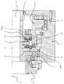
図1は、本発明の実施例の割出しテーブルの側面断面図であり、図2は図1の割出しテーブル内の遊星回転部の詳細構造を示す部分拡大図である。
図1に示すように、割出しテーブルは、本体1と、工作機械のワークを取り付けるテーブル面8と、テーブル面8に固設されるスピンドル9と、駆動源であるモーター20に接続する動力軸4と、動力軸4の回転をスピンドル9へ伝達する回転部12などにより構成されている。
また、テーブル面8とスピンドル9及び動力軸4は、同一の軸芯3を中心に回転可能に構成されている。Embodiments of the present invention will be described below with reference to the drawings.
FIG. 1 is a side sectional view of an indexing table according to an embodiment of the present invention, and FIG. 2 is a partially enlarged view showing a detailed structure of a planetary rotating part in the indexing table of FIG.
As shown in FIG. 1, the indexing table includes a main body 1, a table surface 8 on which a workpiece of a machine tool is mounted, a
The table surface 8, the
本体1は、内部に他の構成要素を収納する空間を有する形状に構成されている。本体1の空間には、ベアリング2を介して動力軸4が、軸芯を中心に回転自在に設けられており、本体1に固着されたモーター20の駆動により回転可能になされている。
動力軸4には、軸芯3と同心に設けられた円筒形状の入力側円筒部23が形成されており、この入力側円筒部23のテーブル面側の端部には、軸芯方向へ凹凸形状が形成されている入力歯車5が設けられている。
入力歯車5は、動力軸へ固定されているので、駆動源であるモーター20の回転駆動により動力軸4が軸芯を中心に回転されると、動力軸4と共に入力歯車5が軸芯3を中心に回転される。The main body 1 is configured in a shape having a space for storing other components therein. In the space of the main body 1, a
The
Since the
また、本体1には、軸芯3と同心に設けられた円筒形状の固定側円筒部24が形成され、この固定側円筒部24には前記入力側円筒部24側の端部に軸芯方向へ凹凸形状が形成されている固定歯車6が設けられている。
固定歯車6は、本体1へ固定されているので、回転運動することなく固定されて本体1へ設けられている。
前記入力歯車と固定歯車は、軸芯方向において並列に配置され、入力歯車と固定歯車の間には両者と係合する回転部12が設けられている。Further, the main body 1 is formed with a cylindrical fixed-side
Since the
The input gear and the fixed gear are arranged in parallel in the axial direction, and a
回転部12はスピンドル9の外周へ円周方向の等分角に複数個(本実施例においては3等分に設けられ3個)備えられている。
回転部12は入力歯車5の回転力をスピンドル9の回転力に変換して伝達し、スピンドル9の回転によりテーブル面8を回転させる。A plurality of rotating
The rotating
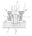
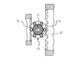
次に回転部12の構成について図2に示す各断面図である図3〜図4を用いて説明する。
スピンドル9の外周には、半径方向外方に突出する3個の棒状の軸部11がスピンドル9へ固着して設けられている。
回転部12は、この軸部11へベアリング27を介して回転自在に設けられ、回転部12は軸芯3に直交する回転軸25を中心に回転可能になされている。
回転部12には、前記入力歯車5と係合する入力側ローラー15と、固定歯車6と係合する固定側ローラー16が設けられている。Next, the configuration of the rotating
On the outer periphery of the
The rotating
The rotating
図2に示す本実施例においては回転部12の下側へ複数の入力側ローラー15を回転部12の回転軸25周りに等分角で配置されて構成されており(本実施例においては、図4に示すように等分角に6個が配置されている)、入力歯車5の凹凸形状部位へ係合するように設けられている。
入力側ローラー15が入力歯車5の凹凸形状部へ係合することで、入力歯車5の軸芯3方向の回転が回転部12の回転軸25の中心(軸芯3方向と直交する)の回転に変換されて伝達される。In the present embodiment shown in FIG. 2, a plurality of
When the
図2に示す本実施例においては、回転部12の上側へ複数の固定側ローラー16を回転部12の回転軸25周りに等分角に配置されて構成されており(本実施例においては、図3に示すように等分角に6個が配置されている)、固定歯車6の凹凸形状へ係合するように設けられている。
固定側ローラー16が固定歯車6の凹凸形状部へ係合することで、回転部12の回転軸25を中心とする回転運動が固定歯車6への回転運動として伝達されずに抑制され、回転部12の軸芯3を中心とする回動運動に変換され、回転部12と固着して備えるスピンドル9の軸芯3を中心とした回転運動として伝達される。In the present embodiment shown in FIG. 2, a plurality of fixed-
When the
また、本体1には付勢手段が2箇所に備えられ、動力軸4と入力歯車5の間に設けられる付勢手段26aと、本体1と固定歯車6との間に設けられる付勢手段26bが備えられている。
付勢手段26aは動力軸4から入力歯車5を軸芯方向の前方(テーブル面側)へ押圧し、入力歯車5をこれと係合する入力側ローラー15へ押し付け、この押し付けられた状態で係合し、回転力が入力歯車5から入力側ローラー15へ伝達される。
付勢手段26bは固定側である本体1から固定歯車6を軸芯方向の後方へ押圧し、固定歯車6をこれと係合する固定側ローラー16へ押し付け、この押し付けられた状態で係合し入力側ローラー15へ伝達される。Further, the main body 1 is provided with urging means at two locations, the urging means 26 a provided between the
The urging means 26a presses the
The urging means 26b presses the
そのため、入力歯車5と入力ローラー15との間、及び固定歯車6と固定側ローラー15との間において常にローラー15、16と歯車5、6が接触状態を保ち、必ず接触が行なわれるのでバックラッシの発生が解消される。
これにより、スピンドル9の回転角度を正確な出力が可能となり、テーブル面8の回転角度の位置精度が良くなり、加工時に正確な割出し位置を実現できる。
本実施例において、付勢手段26a、26bは図1に示すように止め輪を設けて、軸による歯車を軸芯方向へ押圧しているが、付勢手段26は本実施例に限定されるものではなく、油圧シリンダやスプリング構造など軸芯方向へ付勢するものであれば同様な効果を得るものである。Therefore, between the
Thereby, the rotation angle of the
In this embodiment, the urging means 26a and 26b are provided with a retaining ring as shown in FIG. 1 to press the gear by the shaft in the axial direction, but the urging means 26 is limited to this embodiment. The same effect can be obtained as long as it is biased in the axial direction, such as a hydraulic cylinder or a spring structure.
次に本実施例の動作について説明する。
本体1に備えられた駆動源であるモーター20が駆動すると、モーター20に連結された動力軸4が回転力を与えられる。
動力軸4は本体1へベアリング2を介して軸芯3を中心に回転自在に設けられているので、モーター20の回転により、動力軸4は軸芯3を中心に回転運動を行なう。Next, the operation of this embodiment will be described.
When the
Since the
動力軸4が回転すると、動力軸4の軸芯方向のテーブル面側の端部へ形成されている入力側円筒部23も動力軸4と共に回転される。
これにより、入力側円筒部23に形成された入力歯車5も同様に軸芯3を中心として回転される。
入力歯車5へ形成された凹凸形状には回転部12に設けられた入力側係合部13として入力側ローラー15が係合しているので、入力歯車5の軸芯3を中心とした回転運動が入力側ローラー15へ伝達され、回転部12の回転軸25を中心とした回転運動に変換される。When the
Thereby, the
Since the input-
このとき、回転部12へ固定側係合部14として設けられる固定側ローラー16が固定されている本体1に備えられる固定歯車6の凹凸形状へ係合しているので、回転部12へ伝わる回転軸25を中心とした回転運動は抑制され、伝達された回転力によって、固定歯車6と係合しながら回転部12は回転軸25を中心に回転する。
このため、回転部12が回転運動することで回転部12は固定歯車6の円周形状に沿って軸芯3を中心として回動運動する。この回動運動により回転部12が固着して設けられているスピンドル9には軸芯3を中心とした回転運動として回転力が伝達され、スピンドル9は軸芯3を中心に回転する。
このスピンドル9の回転運動によって、スピンドル9の前方へ連結されたテーブル面は軸芯3を中心として回転運動されて、割出しテーブルが回転駆動される。At this time, since the fixed
For this reason, the
Due to the rotational movement of the
この時、付勢手段26により入力歯車5と入力ローラー15との間、及び固定歯車6と固定側ローラー15との間に常に軸芯方向へ押圧力が作用しているので、入力歯車5と入力ローラー15との間、及び固定歯車6と固定側ローラー15との間において常にローラー15、16と歯車5、6が接触状態を保ち、必ず接触が行なわれるのでバックラッシの発生が解消される。 At this time, a pressing force is always applied in the axial direction between the
本実施例において、図1に示すように、スピンドル9の軸芯3部分へ中空部17が設けられている。これにより、スピンドル9へ貫通穴が形成され、棒形状などの長尺のワークをテーブル面へ取り付けることができる。
従来の遊星歯車機構を用いた割出しテーブルにおいては軸芯部位へ太陽歯車(又は太陽ローラー)を配置し、太陽歯車の半径方向外方へ遊星歯車(又は遊星ローラー)を配置する必要があり、半径方向へスペースの確保が難しくスピンドルへ中空部を有すると半径の大きな割出しテーブル形状となってしまう。
しかしながら、本発明の割出しテーブルの構成によれば、入力歯車5と回転部12と固定歯車6の構成が軸芯方向に配置され、半径方向に各構成が配置されていないので、半径方向にスマートな本体形状を実現できる。
これによりスピンドル9へ中空部を備え、且つ半径方向にコンパクトな割出しテーブルを構成することができる。In this embodiment, as shown in FIG. 1, a
In the indexing table using the conventional planetary gear mechanism, it is necessary to arrange the sun gear (or sun roller) on the axial core part, and to arrange the planetary gear (or planetary roller) radially outward of the sun gear, It is difficult to secure a space in the radial direction, and if the spindle has a hollow portion, an index table shape with a large radius is formed.
However, according to the configuration of the indexing table of the present invention, the configuration of the
As a result, a hollow index portion can be formed in the
また、前記実施例において回転部12に備える入力側ローラー15と固定側ローラー16は係合部をローラーで構成しているが、図2に示されるようにこのローラーの形状は略太鼓形状で形成されている。ローラーの形状が略太鼓形状であるので、ローラーと係合する入力歯車5と固定歯車6の形状にテーパーの必要が無い。
ローラーの形状が円筒形の場合にはローラーに係合する歯車には軸芯方向へ向けてテーパーを設けて形状を修正する必要がある。
しかしながら、ローラーの外周形状を略太鼓形状とし外周へ膨らみを有する曲面で形成することで、ローラーが常に歯車に接する構成となされ、ローラーと係合する入力歯車5と固定歯車6の凹凸形状にテーパーの必要が無く、歯車加工を容易に行なうことができる。これにより、歯車製作の製造工数やコストの低減が可能となる。Further, in the embodiment, the
When the roller has a cylindrical shape, it is necessary to correct the shape by providing a taper in the axial direction on the gear engaged with the roller.
However, by forming the outer peripheral shape of the roller into a substantially drum shape and a curved surface having a bulge to the outer periphery, the roller is always in contact with the gear, and the
前記実施例のように回転部12に備える係合部を入力側ローラー15と固定側ローラー16で構成することにより、入力歯車5及び固定歯車6とはローラーで接触するので、歯車同士による接触と異なり、ローラーと歯車との間に滑りが発生しない。このため確実に回転力を伝達でき、動力の伝達効率に非常に優れており、損失なくモーターの回転力を伝達できる。 Since the engaging part provided in the
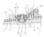
また、本発明の第二実施例として、図5から図7へ割出しテーブルを示す。
前記実施例においては、動力軸4と本体1へ各々入力歯車5と固定歯車6を形成し、スピンドル9に設ける回転部12が入力側ローラー15と固定側ローラー16を有している。これに対して、第二実施例であるテーブルの構造は、スピンドル9へ設けた遊星回転機構である回転部材30が歯車を形成し、その回転部材30の歯車へ係合するローラーが入力側である動力軸4と固定側である本体1へ各々設けられている構造である。FIG. 5 to FIG. 7 show an indexing table as a second embodiment of the present invention.
In the above embodiment, the
第二実施例の割出しテーブルにおいて、本体1は、それぞれベアリング31を介して回転自在に設けら工作機械のワークを取り付けるテーブル面8と、該テーブル面8へ回転力を与える駆動源であるモーター20と接続する動力軸4を備えている。
テーブル面8は回転中心を軸芯3とする円筒形状のスピンドル9をボルト42により固着されて設けており、スピンドル9が回転することでテーブル面8も同時に回転するようになされている。スピンドル9には動力軸4の回転をスピンドル9へ減速して伝達する複数の回転部材30が設けられている。また、テーブル面8とスピンドル9と動力軸4は、同一の軸芯3を中心に回転可能に構成されている。In the indexing table of the second embodiment, the main body 1 is provided with a table surface 8 on which a workpiece of a machine tool is rotatably provided via a
The table surface 8 is provided with a
本体1は、内部へスピンドル9と動力軸4を収める空間を軸芯部分へ形成している。本体1の空間には、動力軸4が、本体1へ固着して設けられる動力源4であるモーター20の回転を受けて軸芯中心に回転自在となすようにスピンド9ルの外周へベアリング31を介して配置されている。
動力軸4には、軸芯3と同心に設けられた円筒形状の入力側円筒部23が形成されており、この入力側円筒部23のテーブル面側の端部には、入力側ローラー32が径方向外方へ向けて周方向の等分角に複数個を全周に渡り配列されて設けられており、後述する係合ギア35と係合するようになされている。入力側ローラー32は、動力軸4へ固定されて備えられているので、駆動源であるモーター20の回転駆動により動力軸4が軸芯3を中心に回転すると、動力軸4と共に入力側ローラー32が軸芯3を中心に回転される。The main body 1 has a space for accommodating the
The
入力側ローラー32は、入力側円筒部23から径方向外方へ突出して設けられる軸部材33と、その軸部材33の外方へ回転自在に設けられるローラー体34を備えている。ローラー体34の外周形状は略太鼓形状の円筒形で形成され、側方曲面へ後述する係合ギア35の凹凸形状部40へ係合するようになされている。
また、回転しない本体1には、軸芯3と同心に設けられた円筒形状の固定側円筒部24が形成され、この固定側円筒部24の前記入力側円筒部側の端部には、固定側ローラー36が径方向外方へ向けて周方向の等分角に複数個を全周に渡り配列されて設けられている。
固定側ローラー36は本体1へ固定されて備えられているので、回転運動することなく固定されて本体1へ設けられている。前記入力側ローラー32と固定側ローラー36は、軸芯方向において並列に配置され、入力側ローラー32と固定側ローラー36との間には両者ローラーと係合する係合ギア35を有する回転部材30が配置される。The
The non-rotating main body 1 is formed with a cylindrical fixed side
Since the fixed
前記入力側ローラー32と同様に固定側ローラー36も、固定側円筒部24から外方へ突出して設けられる軸部材33と、その軸部材33の外方へ回転自在に設けられるローラー体34を備えている。ローラー体34の外周形状は略太鼓形状の円筒形で形成され、側方曲面へ前記係合ギア35の凹凸形状部40へ係合するようになされている。
回転部材30は、スピンドル9の外周へ円周方向の略等分角に複数個(本実施例においては、略5等分に設けられた5個)備えられている。回転部材30は動力軸4の回転力を、スピンドル9の回転力に変換して伝達し、スピンドル9の回転によりテーブル面8を回転させる。Similarly to the
A plurality of rotating
次に回転部材30の構成について説明する。
回転部材30は、スピンドル9の外周へ径方向外方に突出して設けられた5個の棒状の軸部37へベアリング38を介して回転自在に取り付けられている。この軸部37を回転中心としてベアリング38を介して回転自在に略円盤形状の回転体39がひとつの軸部37に対してひとつずつ挿入され、回転体39は軸芯3に直交する軸部37を中心に回転可能になされている。Next, the configuration of the rotating
The rotating
回転体39には、その外周部位の外方へ向けて入力側ローラー32及び固定側ローラー36とそれぞれ係合するために凹凸形状部40を形成する係合ギア35が設けられている。
係合ギア35は一種のカムフォロアであり、入力側ローラー32及び固定側ローラー36と係合しつつ回転部材30も軸部37を中心に回転しながら、軸芯3を中心に回動するように断面形状が形成されている。
これは、入力側ローラー32及び固定側ローラー36と係合ギア35が係合する際には、円周状に配置された入力側ローラー32及び固定側ローラー36に対して、回転部材30自体が回転しながら係合するために、次第に近接しつつ係合しながら、最も近い位置で係合した後次第に遠ざかりつつ離合するようになされるためである。
そのため、係合ギア35の凹凸形状部4の形状は、並列に隣り合う歯同士の間隔において、下方から上方へ扇が徐々に開くように間隔が変位するような通常の歯形とは異なる特異形状になされている。The rotating
The
This is because when the
Therefore, the shape of the concavo-
次に、本実施例の動作について説明する。
本体1へ固着されて設けられた駆動源であるモーター20が回転を駆動すると、回転自在にモーター20と連結されている動力軸4へ回転力が与えられる。
動力軸4はスピンドル9へベアリング31を介して軸芯3を中心に回転自在に設けられているので、モーター20の回転に合わせて、動力軸4は軸芯3を中心で回転運動を行なう。
動力軸4の回転に伴い、動力軸4の端部へ形成されている入力側円筒部23も動力軸4と共に回転する。これにより、入力側円筒部23へ設けられた入力側ローラー32も同様に軸芯3を中心に回転される。
この入力側ローラー32は、回転部材30の回転体39の外周へ設けられた係合ギア35の凹凸形状部40へ係合しているので、入力側ローラー32の軸心3を中心とした回転運動が、係合ギア35へ伝達され、回転部材30の回転軸廻りの回転運動に変換される。Next, the operation of this embodiment will be described.
When the
Since the
As the
Since the
このとき、回転部材30へ設けられる係合ギア35の凹凸形状部40が、固定されている本体1の固定側円筒部24へ備えられている固定側ローラー36に係合しているので、回転部材30へ伝わる回転運動が抑制され、回転部材30は伝達された回転力によって固定側ローラー36へ係合しながら回転軸廻りで回転する。
このため、回転部材30が回転運動することで、回転部材30は固定側ローラー36の配置される円周状に沿って回動される。この円周状の回動運動により回転部材30が設けられるスピンドル9には軸芯3を中心に回転する作用力が発生する。At this time, the concavo-
For this reason, the rotating
このスピンドル9の回転運動によって、スピンドル9の前方へ連結されたテーブル面8が軸芯3を中心に回転運動されて、割出しテーブルが回転駆動される。
この時、前記実施例と同様に入力側ローラー32及び固定側ローラー36を軸芯方向で回転部材側へ押圧する付勢手段41a、41bが設けられているので、入力側ローラー32と係合ギア35との間、及び固定側ローラー36と係合ギア35との間において、常に互いに接触状態を維持でき、バックラッシの発生が解消される。これにより高精度の割出しが可能となり、高精度の加工を実施することができる。
By the rotational movement of the
At this time, since the urging means 41a and 41b for pressing the
1 本体
3 軸芯
4 動力軸
5 入力歯車
6 固定歯車
9 スピンドル
12 回転部
15 入力側ローラー
16 固定側ローラー
25 回転軸
26 付勢手段
30 回転部材
32 入力側ローラー
35 係合ギア
36 固定側ローラー
39 回転体
41 付勢手段DESCRIPTION OF SYMBOLS 1
Claims (3)
Translated fromJapanesePriority Applications (1)
| Application Number | Priority Date | Filing Date | Title |
|---|---|---|---|
| JP2009154933AJP5377114B2 (en) | 2008-10-29 | 2009-06-30 | Indexing table for machine tools |
Applications Claiming Priority (3)
| Application Number | Priority Date | Filing Date | Title |
|---|---|---|---|
| JP2008278851 | 2008-10-29 | ||
| JP2008278851 | 2008-10-29 | ||
| JP2009154933AJP5377114B2 (en) | 2008-10-29 | 2009-06-30 | Indexing table for machine tools |
Publications (3)
| Publication Number | Publication Date |
|---|---|
| JP2010131740Atrue JP2010131740A (en) | 2010-06-17 |
| JP2010131740A5 JP2010131740A5 (en) | 2012-08-16 |
| JP5377114B2 JP5377114B2 (en) | 2013-12-25 |
Family
ID=42343588
Family Applications (1)
| Application Number | Title | Priority Date | Filing Date |
|---|---|---|---|
| JP2009154933AActiveJP5377114B2 (en) | 2008-10-29 | 2009-06-30 | Indexing table for machine tools |
Country Status (1)
| Country | Link |
|---|---|
| JP (1) | JP5377114B2 (en) |
Cited By (3)
| Publication number | Priority date | Publication date | Assignee | Title |
|---|---|---|---|---|
| JP2015174187A (en)* | 2014-03-17 | 2015-10-05 | 株式会社北川鉄工所 | Rotary table with variable reduction ratio |
| JP2016182663A (en)* | 2015-03-27 | 2016-10-20 | 株式会社北川鉄工所 | Rotating table capable of switching reduction ratio |
| JP2023014806A (en)* | 2021-07-19 | 2023-01-31 | テクノダイナミックス株式会社 | barrel cam device |
Citations (6)
| Publication number | Priority date | Publication date | Assignee | Title |
|---|---|---|---|---|
| US2182458A (en)* | 1936-12-05 | 1939-12-05 | Vickers Inc | Frictional gearing |
| US4297919A (en)* | 1979-04-19 | 1981-11-03 | Kuehnle Manfred R | Mechanical power transmission method and means |
| JPH03149449A (en)* | 1989-11-01 | 1991-06-26 | Ichiro Kamimura | Electromotive differential type thrust generator |
| JP2003028269A (en)* | 2001-07-12 | 2003-01-29 | Masaaki Yamashita | Transmission |
| JP2006046405A (en)* | 2004-08-02 | 2006-02-16 | Ogino Kogyo Kk | Shift gear device |
| JP2008213098A (en)* | 2007-03-06 | 2008-09-18 | Mitsubishi Heavy Ind Ltd | Index table |
- 2009
- 2009-06-30JPJP2009154933Apatent/JP5377114B2/enactiveActive
Patent Citations (6)
| Publication number | Priority date | Publication date | Assignee | Title |
|---|---|---|---|---|
| US2182458A (en)* | 1936-12-05 | 1939-12-05 | Vickers Inc | Frictional gearing |
| US4297919A (en)* | 1979-04-19 | 1981-11-03 | Kuehnle Manfred R | Mechanical power transmission method and means |
| JPH03149449A (en)* | 1989-11-01 | 1991-06-26 | Ichiro Kamimura | Electromotive differential type thrust generator |
| JP2003028269A (en)* | 2001-07-12 | 2003-01-29 | Masaaki Yamashita | Transmission |
| JP2006046405A (en)* | 2004-08-02 | 2006-02-16 | Ogino Kogyo Kk | Shift gear device |
| JP2008213098A (en)* | 2007-03-06 | 2008-09-18 | Mitsubishi Heavy Ind Ltd | Index table |
Cited By (5)
| Publication number | Priority date | Publication date | Assignee | Title |
|---|---|---|---|---|
| JP2015174187A (en)* | 2014-03-17 | 2015-10-05 | 株式会社北川鉄工所 | Rotary table with variable reduction ratio |
| JP2016182663A (en)* | 2015-03-27 | 2016-10-20 | 株式会社北川鉄工所 | Rotating table capable of switching reduction ratio |
| JP2023014806A (en)* | 2021-07-19 | 2023-01-31 | テクノダイナミックス株式会社 | barrel cam device |
| JP7680739B2 (en) | 2021-07-19 | 2025-05-21 | テクノダイナミックス株式会社 | Barrel Cam Device |
| US12409524B2 (en) | 2021-07-19 | 2025-09-09 | Techno Dynamics, Inc. | Barrel cam device |
Also Published As
| Publication number | Publication date |
|---|---|
| JP5377114B2 (en) | 2013-12-25 |
Similar Documents
| Publication | Publication Date | Title |
|---|---|---|
| JP6028055B2 (en) | Reducer with motor | |
| JP5377114B2 (en) | Indexing table for machine tools | |
| JP6356514B2 (en) | Decelerator | |
| JP6344937B2 (en) | Rotary table with variable reduction ratio | |
| JP2017009107A (en) | Differential device and processing device using the same | |
| JP5816568B2 (en) | Gear motor | |
| EP0909909B1 (en) | Rotary power transmission apparatus | |
| JP6757149B2 (en) | Gear device | |
| JP2016125536A (en) | Automatic transmission | |
| JP6472697B2 (en) | Rotary table with switchable reduction ratio | |
| TW201000786A (en) | Output structure for a reduction gearbox | |
| JP2010131740A5 (en) | ||
| JP5232763B2 (en) | Micro traction drive | |
| JPWO2019078088A1 (en) | transmission | |
| CN106286716B (en) | Power transmission device using internally tangent cam and cylindrical pinion | |
| JP6265061B2 (en) | Planetary roller traction drive device | |
| JP6369274B2 (en) | Inscribed mesh planetary gear mechanism | |
| JP5620338B2 (en) | Power tools | |
| JP6568749B2 (en) | Planetary roller type power transmission device | |
| JP2009028866A (en) | Indexing mechanism | |
| JPH09168910A (en) | Tool holder | |
| JP6175298B2 (en) | Balance weight device | |
| WO2016027323A1 (en) | Facing-type strain wave gearing | |
| JPH0621621B2 (en) | Planetary roller reducer | |
| KR20150025165A (en) | Speed-reduction transmission bearing |
Legal Events
| Date | Code | Title | Description |
|---|---|---|---|
| A521 | Request for written amendment filed | Free format text:JAPANESE INTERMEDIATE CODE: A523 Effective date:20120629 | |
| A621 | Written request for application examination | Free format text:JAPANESE INTERMEDIATE CODE: A621 Effective date:20120629 | |
| A977 | Report on retrieval | Free format text:JAPANESE INTERMEDIATE CODE: A971007 Effective date:20130821 | |
| TRDD | Decision of grant or rejection written | ||
| A01 | Written decision to grant a patent or to grant a registration (utility model) | Free format text:JAPANESE INTERMEDIATE CODE: A01 Effective date:20130903 | |
| A61 | First payment of annual fees (during grant procedure) | Free format text:JAPANESE INTERMEDIATE CODE: A61 Effective date:20130924 | |
| R150 | Certificate of patent or registration of utility model | Ref document number:5377114 Country of ref document:JP Free format text:JAPANESE INTERMEDIATE CODE: R150 | |
| R250 | Receipt of annual fees | Free format text:JAPANESE INTERMEDIATE CODE: R250 | |
| R250 | Receipt of annual fees | Free format text:JAPANESE INTERMEDIATE CODE: R250 | |
| R250 | Receipt of annual fees | Free format text:JAPANESE INTERMEDIATE CODE: R250 | |
| R250 | Receipt of annual fees | Free format text:JAPANESE INTERMEDIATE CODE: R250 | |
| R250 | Receipt of annual fees | Free format text:JAPANESE INTERMEDIATE CODE: R250 |