JP2010110050A - Charging cable unit - Google Patents
Charging cable unitDownload PDFInfo
- Publication number
- JP2010110050A JP2010110050AJP2008277394AJP2008277394AJP2010110050AJP 2010110050 AJP2010110050 AJP 2010110050AJP 2008277394 AJP2008277394 AJP 2008277394AJP 2008277394 AJP2008277394 AJP 2008277394AJP 2010110050 AJP2010110050 AJP 2010110050A
- Authority
- JP
- Japan
- Prior art keywords
- power
- unit
- charging
- display
- leakage
- Prior art date
- Legal status (The legal status is an assumption and is not a legal conclusion. Google has not performed a legal analysis and makes no representation as to the accuracy of the status listed.)
- Withdrawn
Links
Images


Classifications
- B—PERFORMING OPERATIONS; TRANSPORTING
- B60—VEHICLES IN GENERAL
- B60L—PROPULSION OF ELECTRICALLY-PROPELLED VEHICLES; SUPPLYING ELECTRIC POWER FOR AUXILIARY EQUIPMENT OF ELECTRICALLY-PROPELLED VEHICLES; ELECTRODYNAMIC BRAKE SYSTEMS FOR VEHICLES IN GENERAL; MAGNETIC SUSPENSION OR LEVITATION FOR VEHICLES; MONITORING OPERATING VARIABLES OF ELECTRICALLY-PROPELLED VEHICLES; ELECTRIC SAFETY DEVICES FOR ELECTRICALLY-PROPELLED VEHICLES
- B60L3/00—Electric devices on electrically-propelled vehicles for safety purposes; Monitoring operating variables, e.g. speed, deceleration or energy consumption
- B60L3/0023—Detecting, eliminating, remedying or compensating for drive train abnormalities, e.g. failures within the drive train
- B60L3/0069—Detecting, eliminating, remedying or compensating for drive train abnormalities, e.g. failures within the drive train relating to the isolation, e.g. ground fault or leak current
- B—PERFORMING OPERATIONS; TRANSPORTING
- B60—VEHICLES IN GENERAL
- B60L—PROPULSION OF ELECTRICALLY-PROPELLED VEHICLES; SUPPLYING ELECTRIC POWER FOR AUXILIARY EQUIPMENT OF ELECTRICALLY-PROPELLED VEHICLES; ELECTRODYNAMIC BRAKE SYSTEMS FOR VEHICLES IN GENERAL; MAGNETIC SUSPENSION OR LEVITATION FOR VEHICLES; MONITORING OPERATING VARIABLES OF ELECTRICALLY-PROPELLED VEHICLES; ELECTRIC SAFETY DEVICES FOR ELECTRICALLY-PROPELLED VEHICLES
- B60L53/00—Methods of charging batteries, specially adapted for electric vehicles; Charging stations or on-board charging equipment therefor; Exchange of energy storage elements in electric vehicles
- B60L53/10—Methods of charging batteries, specially adapted for electric vehicles; Charging stations or on-board charging equipment therefor; Exchange of energy storage elements in electric vehicles characterised by the energy transfer between the charging station and the vehicle
- B60L53/14—Conductive energy transfer
- B60L53/16—Connectors, e.g. plugs or sockets, specially adapted for charging electric vehicles
- B—PERFORMING OPERATIONS; TRANSPORTING
- B60—VEHICLES IN GENERAL
- B60L—PROPULSION OF ELECTRICALLY-PROPELLED VEHICLES; SUPPLYING ELECTRIC POWER FOR AUXILIARY EQUIPMENT OF ELECTRICALLY-PROPELLED VEHICLES; ELECTRODYNAMIC BRAKE SYSTEMS FOR VEHICLES IN GENERAL; MAGNETIC SUSPENSION OR LEVITATION FOR VEHICLES; MONITORING OPERATING VARIABLES OF ELECTRICALLY-PROPELLED VEHICLES; ELECTRIC SAFETY DEVICES FOR ELECTRICALLY-PROPELLED VEHICLES
- B60L53/00—Methods of charging batteries, specially adapted for electric vehicles; Charging stations or on-board charging equipment therefor; Exchange of energy storage elements in electric vehicles
- B60L53/10—Methods of charging batteries, specially adapted for electric vehicles; Charging stations or on-board charging equipment therefor; Exchange of energy storage elements in electric vehicles characterised by the energy transfer between the charging station and the vehicle
- B60L53/14—Conductive energy transfer
- B60L53/18—Cables specially adapted for charging electric vehicles
- B—PERFORMING OPERATIONS; TRANSPORTING
- B60—VEHICLES IN GENERAL
- B60L—PROPULSION OF ELECTRICALLY-PROPELLED VEHICLES; SUPPLYING ELECTRIC POWER FOR AUXILIARY EQUIPMENT OF ELECTRICALLY-PROPELLED VEHICLES; ELECTRODYNAMIC BRAKE SYSTEMS FOR VEHICLES IN GENERAL; MAGNETIC SUSPENSION OR LEVITATION FOR VEHICLES; MONITORING OPERATING VARIABLES OF ELECTRICALLY-PROPELLED VEHICLES; ELECTRIC SAFETY DEVICES FOR ELECTRICALLY-PROPELLED VEHICLES
- B60L53/00—Methods of charging batteries, specially adapted for electric vehicles; Charging stations or on-board charging equipment therefor; Exchange of energy storage elements in electric vehicles
- B60L53/30—Constructional details of charging stations
- B60L53/305—Communication interfaces
- B—PERFORMING OPERATIONS; TRANSPORTING
- B60—VEHICLES IN GENERAL
- B60L—PROPULSION OF ELECTRICALLY-PROPELLED VEHICLES; SUPPLYING ELECTRIC POWER FOR AUXILIARY EQUIPMENT OF ELECTRICALLY-PROPELLED VEHICLES; ELECTRODYNAMIC BRAKE SYSTEMS FOR VEHICLES IN GENERAL; MAGNETIC SUSPENSION OR LEVITATION FOR VEHICLES; MONITORING OPERATING VARIABLES OF ELECTRICALLY-PROPELLED VEHICLES; ELECTRIC SAFETY DEVICES FOR ELECTRICALLY-PROPELLED VEHICLES
- B60L53/00—Methods of charging batteries, specially adapted for electric vehicles; Charging stations or on-board charging equipment therefor; Exchange of energy storage elements in electric vehicles
- B60L53/60—Monitoring or controlling charging stations
- B60L53/62—Monitoring or controlling charging stations in response to charging parameters, e.g. current, voltage or electrical charge
- B—PERFORMING OPERATIONS; TRANSPORTING
- B60—VEHICLES IN GENERAL
- B60L—PROPULSION OF ELECTRICALLY-PROPELLED VEHICLES; SUPPLYING ELECTRIC POWER FOR AUXILIARY EQUIPMENT OF ELECTRICALLY-PROPELLED VEHICLES; ELECTRODYNAMIC BRAKE SYSTEMS FOR VEHICLES IN GENERAL; MAGNETIC SUSPENSION OR LEVITATION FOR VEHICLES; MONITORING OPERATING VARIABLES OF ELECTRICALLY-PROPELLED VEHICLES; ELECTRIC SAFETY DEVICES FOR ELECTRICALLY-PROPELLED VEHICLES
- B60L2240/00—Control parameters of input or output; Target parameters
- B60L2240/10—Vehicle control parameters
- B60L2240/36—Temperature of vehicle components or parts
- B—PERFORMING OPERATIONS; TRANSPORTING
- B60—VEHICLES IN GENERAL
- B60L—PROPULSION OF ELECTRICALLY-PROPELLED VEHICLES; SUPPLYING ELECTRIC POWER FOR AUXILIARY EQUIPMENT OF ELECTRICALLY-PROPELLED VEHICLES; ELECTRODYNAMIC BRAKE SYSTEMS FOR VEHICLES IN GENERAL; MAGNETIC SUSPENSION OR LEVITATION FOR VEHICLES; MONITORING OPERATING VARIABLES OF ELECTRICALLY-PROPELLED VEHICLES; ELECTRIC SAFETY DEVICES FOR ELECTRICALLY-PROPELLED VEHICLES
- B60L2250/00—Driver interactions
- B60L2250/10—Driver interactions by alarm
- Y—GENERAL TAGGING OF NEW TECHNOLOGICAL DEVELOPMENTS; GENERAL TAGGING OF CROSS-SECTIONAL TECHNOLOGIES SPANNING OVER SEVERAL SECTIONS OF THE IPC; TECHNICAL SUBJECTS COVERED BY FORMER USPC CROSS-REFERENCE ART COLLECTIONS [XRACs] AND DIGESTS
- Y02—TECHNOLOGIES OR APPLICATIONS FOR MITIGATION OR ADAPTATION AGAINST CLIMATE CHANGE
- Y02T—CLIMATE CHANGE MITIGATION TECHNOLOGIES RELATED TO TRANSPORTATION
- Y02T10/00—Road transport of goods or passengers
- Y02T10/60—Other road transportation technologies with climate change mitigation effect
- Y02T10/70—Energy storage systems for electromobility, e.g. batteries
- Y—GENERAL TAGGING OF NEW TECHNOLOGICAL DEVELOPMENTS; GENERAL TAGGING OF CROSS-SECTIONAL TECHNOLOGIES SPANNING OVER SEVERAL SECTIONS OF THE IPC; TECHNICAL SUBJECTS COVERED BY FORMER USPC CROSS-REFERENCE ART COLLECTIONS [XRACs] AND DIGESTS
- Y02—TECHNOLOGIES OR APPLICATIONS FOR MITIGATION OR ADAPTATION AGAINST CLIMATE CHANGE
- Y02T—CLIMATE CHANGE MITIGATION TECHNOLOGIES RELATED TO TRANSPORTATION
- Y02T10/00—Road transport of goods or passengers
- Y02T10/60—Other road transportation technologies with climate change mitigation effect
- Y02T10/7072—Electromobility specific charging systems or methods for batteries, ultracapacitors, supercapacitors or double-layer capacitors
- Y—GENERAL TAGGING OF NEW TECHNOLOGICAL DEVELOPMENTS; GENERAL TAGGING OF CROSS-SECTIONAL TECHNOLOGIES SPANNING OVER SEVERAL SECTIONS OF THE IPC; TECHNICAL SUBJECTS COVERED BY FORMER USPC CROSS-REFERENCE ART COLLECTIONS [XRACs] AND DIGESTS
- Y02—TECHNOLOGIES OR APPLICATIONS FOR MITIGATION OR ADAPTATION AGAINST CLIMATE CHANGE
- Y02T—CLIMATE CHANGE MITIGATION TECHNOLOGIES RELATED TO TRANSPORTATION
- Y02T90/00—Enabling technologies or technologies with a potential or indirect contribution to GHG emissions mitigation
- Y02T90/10—Technologies relating to charging of electric vehicles
- Y02T90/12—Electric charging stations
- Y—GENERAL TAGGING OF NEW TECHNOLOGICAL DEVELOPMENTS; GENERAL TAGGING OF CROSS-SECTIONAL TECHNOLOGIES SPANNING OVER SEVERAL SECTIONS OF THE IPC; TECHNICAL SUBJECTS COVERED BY FORMER USPC CROSS-REFERENCE ART COLLECTIONS [XRACs] AND DIGESTS
- Y02—TECHNOLOGIES OR APPLICATIONS FOR MITIGATION OR ADAPTATION AGAINST CLIMATE CHANGE
- Y02T—CLIMATE CHANGE MITIGATION TECHNOLOGIES RELATED TO TRANSPORTATION
- Y02T90/00—Enabling technologies or technologies with a potential or indirect contribution to GHG emissions mitigation
- Y02T90/10—Technologies relating to charging of electric vehicles
- Y02T90/14—Plug-in electric vehicles
- Y—GENERAL TAGGING OF NEW TECHNOLOGICAL DEVELOPMENTS; GENERAL TAGGING OF CROSS-SECTIONAL TECHNOLOGIES SPANNING OVER SEVERAL SECTIONS OF THE IPC; TECHNICAL SUBJECTS COVERED BY FORMER USPC CROSS-REFERENCE ART COLLECTIONS [XRACs] AND DIGESTS
- Y02—TECHNOLOGIES OR APPLICATIONS FOR MITIGATION OR ADAPTATION AGAINST CLIMATE CHANGE
- Y02T—CLIMATE CHANGE MITIGATION TECHNOLOGIES RELATED TO TRANSPORTATION
- Y02T90/00—Enabling technologies or technologies with a potential or indirect contribution to GHG emissions mitigation
- Y02T90/10—Technologies relating to charging of electric vehicles
- Y02T90/16—Information or communication technologies improving the operation of electric vehicles
Landscapes
- Engineering & Computer Science (AREA)
- Power Engineering (AREA)
- Transportation (AREA)
- Mechanical Engineering (AREA)
- Life Sciences & Earth Sciences (AREA)
- Sustainable Development (AREA)
- Sustainable Energy (AREA)
- Emergency Protection Circuit Devices (AREA)
- Charge And Discharge Circuits For Batteries Or The Like (AREA)
- Secondary Cells (AREA)
- Electric Propulsion And Braking For Vehicles (AREA)
Abstract
Description
Translated fromJapanese本発明は、充電ケーブルユニットに関するものである。 The present invention relates to a charging cable unit.
電気自動車に搭載された二次電池に充電電流を供給する充電装置(例えば特許文献1参照)や、宅外などに設置されたコンセントを供給源として上記二次電池への充電を可能とする充電ケーブルユニットなどが従来から提供されている。 Charging that enables charging of the secondary battery using a charging device (see, for example, Patent Document 1) that supplies a charging current to a secondary battery mounted on an electric vehicle or an outlet installed outside the house. Cable units and the like have been conventionally provided.
図10(a)は上記充電ケーブルユニットの一例を示しており、ケーブル1の一端側に設けられた機器接続用コネクタ3を電気自動車側のコネクタに接続するとともに、ケーブル1の他端側に設けられた差込プラグ2を商用電源のコンセントAに差込接続することで電気自動車Cに商用電源が供給され、電気自動車C側で内蔵する二次電池の充電が行われるようになっている。なお、図10(b)は漏電遮断装置5を備えた充電ケーブルユニットB’を示しており、当該漏電遮断装置5により漏電が検出された場合には、電気自動車Cへの給電が遮断されるようになっている。
上述の図10(a)(b)に示した充電ケーブルユニットB’は、電気自動車Cに電力を供給して二次電池の充電を行わせるものではあるが、電気自動車Cの充電に費やした電力量や電気料金などが把握できるものではなく、また充電経過時間や充電完了時間なども表示されないため、充電が完了したか否かを何度も確認しなければならず、使い勝手がよくなかった。 The charging cable unit B ′ shown in FIGS. 10 (a) and 10 (b) is used to supply electric power to the electric vehicle C to charge the secondary battery, but was spent on charging the electric vehicle C. It is not easy to use because it is not possible to grasp the amount of electricity, electricity bill, etc., and since the charging elapsed time and charging completion time are not displayed, it has to be confirmed repeatedly whether charging is completed or not. .
本発明は上記問題点に鑑みて為されたものであり、その目的とするところは、使い勝手のよい充電ケーブルユニットを提供することにある。 The present invention has been made in view of the above problems, and an object thereof is to provide an easy-to-use charging cable unit.
請求項1の発明は、商用電源が供給されるプラグ受けに着脱自在に接続される差込プラグと、該差込プラグに電源コードを介して電気的に接続され、商用電源の供給を受けて内蔵する二次電池を充電する受電機器側のコネクタに着脱自在に接続される機器接続用コネクタと、受電機器に供給される電力量を積算する電力積算手段と、該電力積算手段の積算結果を表示する表示手段とを備えることを特徴とする。 The invention of
請求項2の発明は、表示手段は、電力積算手段の積算電力量を電気料金に換算した換算値または充電経過時間のうち少なくとも何れか一方を表示することを特徴とする。 The invention according to
請求項3の発明は、受電機器から送信される充電情報を受信する受信手段を備え、表示手段は、受信手段が受信した充電情報に含まれる充電完了予定時間を表示することを特徴とする。 According to a third aspect of the present invention, there is provided receiving means for receiving charging information transmitted from a power receiving device, and the display means displays a scheduled charging completion time included in the charging information received by the receiving means.
請求項4の発明は、受電機器の充電完了を知らせる報知音を出力する報知手段を備えることを特徴とする。 According to a fourth aspect of the present invention, there is provided an informing means for outputting an informing sound informing completion of charging of the power receiving device.
請求項5の発明は、電源コードに流れる漏洩電流を検出する漏電検知手段と、電源コードの途中に設けられて給電をオン/オフする開閉手段と、漏電検知手段により漏電が検出されると開閉手段を開極させる漏電遮断手段とを備え、表示手段は、漏電検知手段により漏電が検出されると漏電を知らせる表示を行うことを特徴とする。 According to the fifth aspect of the present invention, there is provided a leakage detecting means for detecting a leakage current flowing in the power cord, an opening / closing means provided in the middle of the power cord for turning on / off the power supply, and opening / closing when leakage is detected by the leakage detection means And a leakage current interrupting means for opening the means, and the display means performs a display to notify the leakage when a leakage is detected by the leakage detection means.
請求項6の発明は、差込プラグの温度を検出する温度検出手段と、該温度検出手段の検出結果が予め設定された閾値よりも高い場合には開閉手段を開極させる電路遮断手段とを備えることを特徴とする。 According to a sixth aspect of the present invention, there is provided temperature detecting means for detecting the temperature of the plug, and circuit breaker means for opening the opening / closing means when the detection result of the temperature detecting means is higher than a preset threshold value. It is characterized by providing.
請求項1の発明によれば、受電機器に供給される電力量を表示手段に表示させることで、充電完了時の電力量との関係から充電完了時間の目安にすることができるので、従来例のように充電場所に何度も行かなくてもよく、使い勝手のよい充電ケーブルユニットを提供することができるという効果がある。 According to the first aspect of the present invention, since the amount of power supplied to the power receiving device is displayed on the display means, the charge completion time can be determined from the relationship with the amount of power at the time of completion of charging. Thus, there is an effect that it is possible to provide an easy-to-use charging cable unit without having to go to the charging place many times.
請求項2の発明によれば、受電機器に供給される電力量とともに充電経過時間を表示手段に表示させることで、請求項1と同様に使い勝手のよい充電ケーブルユニットを提供することができる。また、電気料金を表示させた場合には、例えば1回の充電に要する電気料金などを把握することができ、便利であるという効果がある。 According to the invention of
請求項3の発明によれば、充電完了予定時間を表示させることで充電完了までの時間をより正確に把握できるという効果がある。 According to the invention of
請求項4の発明によれば、受電機器の充電完了時に報知音を出力することで、充電場所から離れた場所に居ても充電が完了したことを知ることができるという効果がある。 According to the invention of
請求項5の発明によれば、漏電検知手段により漏電が検出された場合、漏電遮断手段により開閉手段が開極されるので、受電機器への給電を遮断することができて安全性の高い充電システムを提供することができる。また、漏電を知らせる表示を表示手段により行うことで上記表示を行うための専用の表示手段を別に設けなくてもよく、コストアップを抑えることができるという効果がある。 According to the invention of
請求項6の発明によれば、温度検出手段により検出した差込プラグの温度が予め設定された閾値よりも高い場合には、開閉手段を開極させることで受電機器への給電を停止させるので、トラッキング現象などで温度が上昇する場合の安全性を高めることができる。また、開閉手段を兼用することでコストアップを抑えた充電ケーブルユニットを提供することができるという効果がある。 According to the sixth aspect of the present invention, when the temperature of the plug is detected by the temperature detecting means is higher than a preset threshold, the power supply to the power receiving device is stopped by opening the opening / closing means. In addition, safety when the temperature rises due to a tracking phenomenon or the like can be improved. In addition, there is an effect that it is possible to provide a charging cable unit that suppresses an increase in cost by also using the opening / closing means.
以下に本発明に係る充電ケーブルユニットの実施形態を図面に基づいて説明する。本発明に係る充電ケーブルユニットは、宅外などに設置されたコンセントを供給源として、例えば電気自動車に充電のための商用電源を供給するために用いられるものである。 Hereinafter, an embodiment of a charging cable unit according to the present invention will be described with reference to the drawings. The charging cable unit according to the present invention is used to supply a commercial power source for charging to an electric vehicle, for example, using an outlet installed outside the house as a supply source.
(実施形態1)
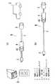
図1(a)は実施形態1の充電ケーブルユニットBを用いた概略システム図であり、本実施形態の充電ケーブルユニットBは、商用電源が供給されるコンセント(プラグ受け)(例えば埋込コンセントや防水コンセントなど)Aに着脱自在に接続される差込プラグ2と、差込プラグ2に電源コード1を介して電気的に接続され、商用電源の供給を受けて内蔵する二次電池を充電する電気自動車(受電機器)C側のコネクタ(図示せず)に着脱自在に接続される機器接続用コネクタ3と、電源コード1の途中に設けられた表示装置4とを備えている。なお、機器接続用コネクタ3については従来周知のものを採用しており、詳細な説明は省略する。ここに、本実施形態の電気自動車Cは、二次電池(バッテリ)のみを動力源とする自動車を含むとともに、二次電池とガソリンとを動力源として併用する所謂ハイブリッド自動車を含むものとする。(Embodiment 1)
FIG. 1A is a schematic system diagram using the charging cable unit B of the first embodiment. The charging cable unit B of the present embodiment has an outlet (plug receptacle) to which commercial power is supplied (for example, an embedded outlet or
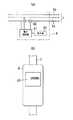
表示装置4は、電気自動車Cの充電情報などを表示するためのものであり、図2(a)に示すように一方の電源線1aに流れる電流を測定する電流測定部(例えばカレントトランスなど)43と、電流測定部43の測定結果および自己に供給される電源電圧から電気自動車Cに供給される電力量を積算する電力積算部(電力積算手段)41と、電力積算部41の積算結果を表示する表示部(表示手段)42とを備えている。なお、図2(a)中の1bはアース線を示している。 The
表示部42は、例えば液晶パネルからなり、図2(b)に示すように直方体状の器体の一側面に露設され、電気自動車Cへの給電開始からの累積電力量(電力積算部41による積算結果)を数値表示する。 The
ここで、機器接続用コネクタ3を電気自動車C側のコネクタに接続するとともに、差込プラグ2をコンセントAに差し込むと電気自動車Cに商用電源が供給され、電気自動車C側で内蔵する二次電池の充電が行われるのであるが、このとき電力積算部41では、電流測定部43の測定結果および自己に供給される電源電圧に基づいて充電に費やした電力量が積算され、さらに電力積算部41の積算結果は表示部42に表示される(図2(b)参照)。 Here, when the
而して、本実施形態によれば、電気自動車Cに供給される電力量を表示部42に表示させることで、充電完了時の電力量との関係から充電完了時間の目安にすることができるので、従来例のように充電場所に何度も行かなくてもよく、使い勝手のよい充電ケーブルユニットBを提供することができる。 Thus, according to the present embodiment, the amount of power supplied to the electric vehicle C is displayed on the
なお、図1(a)では表示装置4を差込プラグ2側に配置しているが、図1(b)に示すように機器接続用コネクタ3側に配置してもよく、表示装置4の配置位置は特に限定されない。また、表示部42は液晶パネルに限定されるものではなく、例えば7セグメントディスプレイを用いてもよい。 In FIG. 1A, the
(実施形態2)
本発明に係る充電ケーブルユニットBの実施形態2を図3および図4に基づいて説明する。実施形態1では、電力積算部41の積算結果(すなわち電気自動車Cの充電に費やした累積電力量)を表示部42に表示させているが、本実施形態では上記積算結果とともに当該積算結果から算出される電気料金や充電経過時間を表示部42に表示させる点で異なっている。なお、それ以外の構成は実施形態1と同様であり、同一の構成要素には同一の符号を付して説明は省略する。(Embodiment 2)
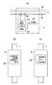
本実施形態の充電ケーブルユニットBの表示装置4は、図3(a)に示すように電力積算部41と、表示部42と、電流測定部43と、制御部44とを備えている。 The
制御部44は、例えばCPUからなり、電力積算部41の積算結果(すなわち電気自動車Cの充電に費やした累積電力量)に基づいて電気料金を算出するとともに、充電経過時間を積算する。なお、充電経過時間については、電流測定部43の検出値が一定値を超えた時間が積算されるようになっている。そして、算出した電気料金や積算した充電経過時間は表示部42に数値表示される。 The
ここで、機器接続用コネクタ3を電気自動車C側のコネクタに接続するとともに、差込プラグ2をコンセントAに差し込むと電気自動車Cに商用電源が供給され、電気自動車C側で内蔵する二次電池の充電が行われるのであるが、このとき電力積算部41では、電流測定部43の測定結果および自己に供給される電源電圧に基づいて充電に費やした電力量が積算され、また制御部44では、電力積算部41の積算結果に基づいて電気料金が算出されるとともに充電経過時間が積算される。そして、表示部42では、図3(b)に示すように使用電力量(電力積算部41の積算結果)とともに電気料金が表示されたり、図3(c)に示すように使用電力量とともに電気料金および充電経過時間が表示される。 Here, when the
次に、図4(a)は本実施形態の他の表示装置4の概略ブロック図であり、図3(a)に示す表示装置4では使用電力量とともに電気料金や充電経過時間を表示させているが(図3(b)および図3(c)参照)、本表示装置4では表示切替スイッチ46を押すことで表示部42に表示される表示内容が切り替えられるようになっている。 Next, FIG. 4A is a schematic block diagram of another
本表示装置4は、図4(a)に示すように電力積算部41と、表示部42と、電流測定部43と、制御部44と、表示部42を制御する表示制御部45と、表示部42の表示内容を切り替えるための表示切替スイッチ46とを備えている。 As shown in FIG. 4A, the
そして、表示内容が、例えば使用電力量と電気料金とに切り替えられるようになっている場合には、図4(b)に示す状態から表示切替スイッチ46を押すたびに、表示制御部45が表示部42の表示を使用電力量と電気料金との間で交互に切り替えるようになっている(図4(c)参照)。 When the display content can be switched between, for example, the amount of power used and the electricity charge, the
また、表示内容が、例えば使用電力量と電気料金と充電経過時間とに切り替えられるようになっている場合には、図4(b)に示す状態から表示切替スイッチ46を押すたびに、表示制御部45が表示部42の表示を使用電力量と電気料金と充電経過時間との間で順番に切り替えるようになっている(図4(d)参照)。なお、表示の順番については本実施形態に限定されるものではない。 In addition, when the display content can be switched to, for example, the amount of electric power used, the electricity charge, and the elapsed charging time, the display control is performed each time the
而して、本実施形態によれば、使用電力量(すなわち電気自動車Cに供給される電力量)とともに充電経過時間を表示させることで、実施形態1と同様に使い勝手のよい充電ケーブルユニットBを提供することができる。また、電気料金を表示させた場合には、例えば1回の充電に要する電気料金などを把握することができ、便利であるという利点がある。 Thus, according to the present embodiment, by displaying the elapsed charging time together with the amount of power used (that is, the amount of power supplied to the electric vehicle C), the charging cable unit B that is easy to use as in the first embodiment can be obtained. Can be provided. In addition, when the electricity charge is displayed, for example, the electricity charge required for one charge can be grasped, and there is an advantage that it is convenient.
(実施形態3)
本発明に係る充電ケーブルユニットBの実施形態3を図5に基づいて説明する。本実施形態では、充電完了予定時間を含む充電情報を電気自動車C側から表示装置4に送信するようにした点で実施形態1,2と異なっている。なお、実施形態1,2と同様の構成については同一の符号を付し、説明は省略する。(Embodiment 3)
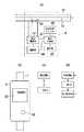
本実施形態の充電ケーブルユニットBの表示装置4は、図5に示すように電力積算部41と、表示部42と、電流測定部43と、制御部44と、表示制御部45と、表示切替スイッチ46と、電気自動車Cから電源線1a,1aを介して伝送される充電情報信号を電源電圧から分離する信号受信部(受信手段)47と、電源系統への信号漏れを防止するためのブロッキングフィルタ48とを備えている。なお、本実施形態では、上記充電情報として充電完了予定時間が含まれているものとする。 As shown in FIG. 5, the
ここで、機器接続用コネクタ3を電気自動車C側のコネクタに接続するとともに、差込プラグ2をコンセントAに差し込むと電気自動車Cに商用電源が供給され、電気自動車C側で内蔵する二次電池の充電が行われるのであるが、このとき電気自動車Cからは電源線1a,1aを介して上記充電情報信号が送信される。一方、表示装置4では、信号受信部47を介して受信した上記充電情報信号が制御部44に入力され、制御部44は上記充電情報とともに電力積算部41の積算結果や電気料金などを表示制御部45に出力する。そして、表示制御部45は、上記充電情報信号に含まれる充電完了予定時間を表示部42に表示させるとともに、上記積算結果や電気料金なども合わせて表示させる。 Here, when the
而して、本実施形態によれば、充電完了予定時間を表示部42に表示させることで充電完了までの時間をより正確に把握できる。 Thus, according to the present embodiment, it is possible to more accurately grasp the time until the completion of charging by displaying the estimated charging completion time on the
なお、本実施形態では、上記充電情報を伝送する方法として所謂電力線搬送通信を用いているが、例えば電気自動車Cおよび表示装置4にそれぞれ無線通信部を設け、無線通信により上記充電情報を伝送してもよい。 In the present embodiment, so-called power line carrier communication is used as a method of transmitting the charging information. For example, the electric vehicle C and the
(実施形態4)
本発明に係る充電ケーブルユニットBの実施形態4を図6〜図8に基づいて説明する。例えばUL規格やIEC規格では、コンセントから30cm以内に漏電遮断装置を設けることが規定されているため、本実施形態ではコンセントAに差込接続される差込プラグ2から30cm以内の位置に漏電遮断装置5を設けており、この点で実施形態1〜3と異なっている。なお、実施形態1〜3と同一の構成要素には同一の符号を付し、説明は省略する。また、本実施形態では、上記漏電遮断装置5を表示装置4に内蔵する形で設けている。(Embodiment 4)
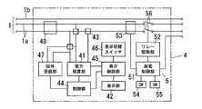
漏電遮断装置5は、図6に示すように各電源線1aとグランドとの間に流れる漏洩電流を検出する漏電検知部53と、電源線1a,1aの電路中にそれぞれ設けたリレー接点56,56を開閉させるリレー駆動部52と、漏電検知部53の検出結果に応じてリレー駆動部52によりリレー接点56,56をオン/オフさせる漏電制御部51と、漏電状態を擬似的に作り出すための漏電テストスイッチ54と、漏電によるトリップ状態を解除するためのリセットスイッチ55とを備えている。ここに、本実施形態では、漏電検知部53により漏電検知手段が構成され、リレー接点56,56により開閉手段が構成され、さらに漏電制御部51およびリレー駆動部52により漏電遮断手段が構成されている。 As shown in FIG. 6, the
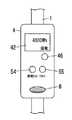
ここで、機器接続用コネクタ3を電気自動車C側のコネクタに接続するとともに、差込プラグ2をコンセントAに差し込むと電気自動車Cに商用電源が供給され、電気自動車C側で内蔵する二次電池の充電が行われるのであるが、このとき表示装置4の表示部42には、図7(a)に示すように使用電力量が表示される。なお、この状態から表示切替スイッチ46を押すたびに、使用電力量→電気料金→充電経過時間→使用電力量…の順番に切り替えられる(図7(b)参照)。ここにおいて、漏電検知部53により漏電(何れかの電源線1aとグランドとの間に漏洩電流が流れた状態)が検出されると、漏電制御部51はリレー駆動部52を用いてリレー接点56,56をオフにし、電気自動車Cへの給電を停止させる。なおこのとき、図7(a)に示すように漏電があったことを知らせる表示(図7(a)では「漏電」)が表示部42に表示される。 Here, when the
また、漏電テストスイッチ54を押した場合には、上述と同様の処理を経てリレー接点56,56がオフになり、擬似的に漏電状態を作り出すことができる。なおこのとき、漏電テスト中であることを表示できるようにしてもよく、例えば図7(c)に示すように照光式の漏電テストスイッチ54を用いて発光表示させてもよい。 In addition, when the
而して、本実施形態によれば、漏電検知部53により漏電が検出された場合、漏電遮断手段(漏電制御部51およびリレー駆動部52)によりリレー接点56,56が開極されるので、電気自動車Cへの給電を遮断することができて安全性の高い充電システムを提供することができる。また、漏電を知らせる表示を表示部42により行うことで上記表示を行うための専用の表示手段を別に設けなくてもよく、コストアップを抑えることができる。 Thus, according to the present embodiment, when the leakage detection is detected by the
次に、図8は本実施形態の他の表示装置4の正面図であり、図6および図7に示した表示装置4に比べてブザー(報知手段)6を設けている点で異なっている。そして、本表示装置4では、電気自動車Cの充電が完了するとブザー6により充電完了を知らせる報知音が出力されるようになっている。なお、本表示装置4では、電気自動車Cから送信される充電情報に含まれる充電完了信号により充電が完了したことを把握できるようになっている。 Next, FIG. 8 is a front view of another
ここで、機器接続用コネクタ3を電気自動車C側のコネクタに接続するとともに、差込プラグ2をコンセントAに差し込むと電気自動車Cに商用電源が供給され、電気自動車C側で内蔵する二次電池の充電が行われるのであるが、所定時間経過後に上記二次電池への充電が完了すると、電気自動車Cからは電源線1a,1aを介して充電完了信号を含む充電情報が送信される。そして、表示装置4の信号受信部47が上記充電情報信号を受信すると、当該充電情報信号は制御部44に入力され、制御部44は当該充電情報信号に含まれる充電完了信号に基づいてブザー6を駆動し、報知音を出力させる。 Here, when the
而して、本表示装置4によれば、電気自動車Cの充電完了時に報知音を出力することで、充電場所から離れた場所に居ても充電が完了したことを知ることができる。 Thus, according to the
なお、本実施形態では制御部44と漏電制御部51とを別々に設けているが、一体に設けてもよい。 In addition, in this embodiment, although the
また、上述した表示装置4、ブザー6および漏電遮断装置5をそれぞれ別個に設け、電源コード1を介して接続するように構成してもよいが、本実施形態のように器体内に表示部42、ブザー6および漏電遮断装置5をまとめて収納し、表示装置4とすることでコンパクトな充電ケーブルユニットBを実現することができる。 Further, the
(実施形態5)
本発明に係る充電ケーブルユニットBの実施形態5を図9に基づいて説明する。本実施形態では、差込プラグ2に設けた温度センサ7の検出結果が予め設定された閾値よりも高くなった場合、電気自動車Cへの給電を停止させるようにした点で実施形態1〜4と異なっている。なお、実施形態1〜4と同一の構成要素には同一の符号を付し、説明は省略する。また、図9(a)は本実施形態の主要部のみを図示しており、基本構成は図6と同様であるものとする。(Embodiment 5)
本実施形態の充電ケーブルユニットBは、図9(b)に示すように差込プラグ2に温度センサ7が設けられており、この温度センサ7の出力信号は漏電制御部51に入力されるようになっている(図9(a)参照)。すなわち、本実施形態の漏電制御部51は、上述した漏電検知部(図示せず)からの漏電検知信号または温度センサ7からの出力信号の何れか一方が入力されると、リレー駆動部52を用いてリレー接点56,56がオフされるようになっている。ここに、本実施形態では、温度センサ7により温度検出手段が構成され、リレー接点56,56により開閉手段が構成され、さらに漏電制御部51およびリレー駆動部52により電路遮断手段が構成されている。すなわち、本実施形態では、実施形態4で説明した漏電遮断手段により電路遮断手段が構成され、さらに開閉手段として実施形態4と共通のリレー接点56,56を用いている。 In the charging cable unit B of the present embodiment, a
ここで、機器接続用コネクタ3を電気自動車C側のコネクタに接続するとともに、差込プラグ2をコンセントAに差し込むと電気自動車Cに商用電源が供給され、電気自動車C側で内蔵する二次電池の充電が行われるのであるが、例えばトラッキング現象により差込プラグ2の温度が上昇し、温度センサ7で検出される温度が予め設定された閾値よりも高くなった場合には、漏電制御部51はリレー駆動部52を用いてリレー接点56,56をオフにし、電気自動車Cへの給電を停止させる。すなわち、本実施形態によれば、トラッキング現象などで差込プラグ2の温度が上昇した場合の安全性を高めることができるのである。また、本実施形態のように、温度上昇に伴う異常停止と漏電に伴う異常停止を1つの制御部(漏電制御部51)で制御することによって、それぞれ別々に制御部を設けた場合に比べて部品点数を削減することができる。 Here, when the
而して、本実施形態によれば、リレー接点56,56を兼用することでコストアップを抑えた充電ケーブルユニットBを提供することができる。特に、本実施形態のように漏電制御部51およびリレー駆動部52も兼用した場合には、より効果的なコストダウンが期待できる。 Thus, according to the present embodiment, it is possible to provide the charging cable unit B in which the increase in cost is suppressed by using the
なお、実施形態1〜5では、受電機器として電気自動車Cを例に挙げているが、受電機器は本例に限定されるものではなく、内蔵する二次電池を充電するものであれば他のものであってもよい。 In the first to fifth embodiments, the electric vehicle C is taken as an example of the power receiving device. However, the power receiving device is not limited to this example, and any other device that charges a built-in secondary battery can be used. It may be a thing.
1 電源コード
2 差込プラグ
3 機器接続用コネクタ
41 電力積算部(電力積算手段)
42 表示部(表示手段)
A コンセント(プラグ受け)
B 充電ケーブルユニット
C 電気自動車DESCRIPTION OF
42 Display section (display means)
A Outlet (plug receptacle)
B Charging cable unit C Electric vehicle
Claims (6)
Translated fromJapanesePriority Applications (5)
| Application Number | Priority Date | Filing Date | Title |
|---|---|---|---|
| JP2008277394AJP2010110050A (en) | 2008-10-28 | 2008-10-28 | Charging cable unit |
| PCT/IB2009/007187WO2010049773A2 (en) | 2008-10-28 | 2009-10-22 | Charging cable unit |
| US13/126,501US8736226B2 (en) | 2008-10-28 | 2009-10-22 | Charging cable, charging cable unit, and charging system for electric vehicle |
| CN200980142900.7ACN102196942B (en) | 2008-10-28 | 2009-10-22 | Charging cable, charging cable unit, and charging system for electric vehicle |
| PCT/IB2009/007194WO2010049775A2 (en) | 2008-10-28 | 2009-10-22 | Charging cable, charging cable unit, and charging system for electric vehicle |
Applications Claiming Priority (1)
| Application Number | Priority Date | Filing Date | Title |
|---|---|---|---|
| JP2008277394AJP2010110050A (en) | 2008-10-28 | 2008-10-28 | Charging cable unit |
Publications (1)
| Publication Number | Publication Date |
|---|---|
| JP2010110050Atrue JP2010110050A (en) | 2010-05-13 |
Family
ID=42298947
Family Applications (1)
| Application Number | Title | Priority Date | Filing Date |
|---|---|---|---|
| JP2008277394AWithdrawnJP2010110050A (en) | 2008-10-28 | 2008-10-28 | Charging cable unit |
Country Status (1)
| Country | Link |
|---|---|
| JP (1) | JP2010110050A (en) |
Cited By (16)
| Publication number | Priority date | Publication date | Assignee | Title |
|---|---|---|---|---|
| JP2011015581A (en)* | 2009-07-03 | 2011-01-20 | San'eisha Mfg Co Ltd | Device for detecting deterioration of quick charger for electric vehicle |
| KR101118125B1 (en) | 2011-08-24 | 2012-03-12 | 주식회사 타이스일렉 | Connector for charging and discharging secondary battery |
| JP2012079629A (en)* | 2010-10-05 | 2012-04-19 | Auto Network Gijutsu Kenkyusho:Kk | Charging cable and cable |
| EP2447107A2 (en) | 2010-10-28 | 2012-05-02 | SMK Corporation | Information providing device, information providing server, vehicle assistance system, navigation device, and charging cable |
| WO2012098819A1 (en)* | 2011-01-19 | 2012-07-26 | 本田技研工業株式会社 | Vehicle charging system |
| JP3177515U (en)* | 2012-04-06 | 2012-08-09 | 愼也 山本 | Integrated wattmeter with cable |
| WO2012117743A1 (en)* | 2011-03-03 | 2012-09-07 | パナソニック株式会社 | Charging cable for electric drive vehicle |
| JP2012244801A (en)* | 2011-05-20 | 2012-12-10 | Panasonic Eco Solutions Switchgear Devices Co Ltd | Charge control device, and charge control system |
| WO2013042988A3 (en)* | 2011-09-23 | 2013-05-23 | 주식회사 엘지화학 | Battery charging system and charging method using same |
| WO2013121472A2 (en) | 2012-02-13 | 2013-08-22 | Toyota Jidosha Kabushiki Kaisha | Feed cable, power supply system and electric-powered vehicle |
| JP2015115264A (en)* | 2013-12-13 | 2015-06-22 | パナソニックIpマネジメント株式会社 | Power supply cord |
| US20170297443A1 (en)* | 2016-04-19 | 2017-10-19 | Hyundai Motor Company | Charging device for vehicle and control method thereof |
| KR20180051154A (en)* | 2016-11-08 | 2018-05-16 | 김태욱 | Electric vehicles, replaceable batteries |
| CN109102951A (en)* | 2018-09-30 | 2018-12-28 | 广东奥美格传导科技股份有限公司 | A kind of self-carrying charging cable and processing method |
| KR102094383B1 (en)* | 2019-03-27 | 2020-03-27 | 곽호영 | battery management device |
| CN111055705A (en)* | 2019-12-31 | 2020-04-24 | 南京康尼新能源汽车零部件有限公司 | Charging connecting cable for electric automobile and working method |
- 2008
- 2008-10-28JPJP2008277394Apatent/JP2010110050A/ennot_activeWithdrawn
Cited By (24)
| Publication number | Priority date | Publication date | Assignee | Title |
|---|---|---|---|---|
| JP2011015581A (en)* | 2009-07-03 | 2011-01-20 | San'eisha Mfg Co Ltd | Device for detecting deterioration of quick charger for electric vehicle |
| JP2012079629A (en)* | 2010-10-05 | 2012-04-19 | Auto Network Gijutsu Kenkyusho:Kk | Charging cable and cable |
| US9233620B2 (en) | 2010-10-28 | 2016-01-12 | Smk Corporation | Information providing device, information providing server, vehicle assistance system, navigation device, and charging cable |
| EP2447107A2 (en) | 2010-10-28 | 2012-05-02 | SMK Corporation | Information providing device, information providing server, vehicle assistance system, navigation device, and charging cable |
| US8669740B2 (en) | 2011-01-19 | 2014-03-11 | Honda Motor Co., Ltd. | Vehicle charging system |
| WO2012098819A1 (en)* | 2011-01-19 | 2012-07-26 | 本田技研工業株式会社 | Vehicle charging system |
| JPWO2012098819A1 (en)* | 2011-01-19 | 2014-06-09 | 本田技研工業株式会社 | Vehicle charging system |
| WO2012117743A1 (en)* | 2011-03-03 | 2012-09-07 | パナソニック株式会社 | Charging cable for electric drive vehicle |
| US9211801B2 (en) | 2011-03-03 | 2015-12-15 | Panasonic Intellectual Property Management Co., Ltd. | Charging cable for electrically-driven vehicle |
| JP2012244801A (en)* | 2011-05-20 | 2012-12-10 | Panasonic Eco Solutions Switchgear Devices Co Ltd | Charge control device, and charge control system |
| KR101118125B1 (en) | 2011-08-24 | 2012-03-12 | 주식회사 타이스일렉 | Connector for charging and discharging secondary battery |
| WO2013042988A3 (en)* | 2011-09-23 | 2013-05-23 | 주식회사 엘지화학 | Battery charging system and charging method using same |
| US9937805B2 (en) | 2011-09-23 | 2018-04-10 | Lg Chem, Ltd. | Battery charging system and charging method using same |
| WO2013121472A2 (en) | 2012-02-13 | 2013-08-22 | Toyota Jidosha Kabushiki Kaisha | Feed cable, power supply system and electric-powered vehicle |
| JP3177515U (en)* | 2012-04-06 | 2012-08-09 | 愼也 山本 | Integrated wattmeter with cable |
| JP2015115264A (en)* | 2013-12-13 | 2015-06-22 | パナソニックIpマネジメント株式会社 | Power supply cord |
| US20170297443A1 (en)* | 2016-04-19 | 2017-10-19 | Hyundai Motor Company | Charging device for vehicle and control method thereof |
| US10093192B2 (en)* | 2016-04-19 | 2018-10-09 | Hyundai Motor Company | Charging device for vehicle and control method thereof |
| KR20180051154A (en)* | 2016-11-08 | 2018-05-16 | 김태욱 | Electric vehicles, replaceable batteries |
| CN109102951A (en)* | 2018-09-30 | 2018-12-28 | 广东奥美格传导科技股份有限公司 | A kind of self-carrying charging cable and processing method |
| CN109102951B (en)* | 2018-09-30 | 2024-02-02 | 广东奥美格传导科技股份有限公司 | Self-carrying charging cable and processing method |
| KR102094383B1 (en)* | 2019-03-27 | 2020-03-27 | 곽호영 | battery management device |
| CN111055705A (en)* | 2019-12-31 | 2020-04-24 | 南京康尼新能源汽车零部件有限公司 | Charging connecting cable for electric automobile and working method |
| CN111055705B (en)* | 2019-12-31 | 2024-02-27 | 南京康尼新能源汽车零部件有限公司 | Charging connection cable for electric automobile and working method |
Similar Documents
| Publication | Publication Date | Title |
|---|---|---|
| JP2010110050A (en) | Charging cable unit | |
| JP4821833B2 (en) | Charging cable unit and charging system using the same | |
| US8736226B2 (en) | Charging cable, charging cable unit, and charging system for electric vehicle | |
| CN101846711B (en) | Fault detection method for detecting leakage paths between power sources and chassis | |
| US11173796B2 (en) | Electric vehicle charging circuit breaker | |
| JP5048963B2 (en) | Battery system | |
| US9762078B2 (en) | Electric vehicle charging system adaptor | |
| TWI514716B (en) | Overcurrent detection device, and charge/discharge system, distribution board, charging controller, charge/discharge device for vehicle and electric apparatus for vehicle, using the overcurrent detction device | |
| US9157941B2 (en) | Electric power information display receptacle module | |
| WO2010049773A2 (en) | Charging cable unit | |
| KR101407735B1 (en) | Electric vehicle and method for detecting status of PRA pre-charge resistor in the same | |
| CN102656766B (en) | Charging device for car | |
| JP2010283902A (en) | Charging apparatus | |
| WO2013181482A4 (en) | Plug-in electric vehicle supply equipment having a process and device for circuit testing | |
| CN104600791A (en) | One-pile multi-charging type DC charging pile for electric vehicle | |
| TW201223054A (en) | Apparatus for energizing a protective device, and associated method | |
| CN103098334A (en) | Device for charging of rechargeable batteries | |
| EP3065255A1 (en) | Power conversion system and connector | |
| KR101754867B1 (en) | Electric vehicle and external equipment of power supply method thereof | |
| CN101697427B (en) | Microprocessor controlled booster apparatus with polarity protection | |
| CN105684234A (en) | Standby Power Cutoff Electric Device and Method Using Speech Recognition | |
| US9172267B2 (en) | Customer device presentation unit | |
| CN104967196A (en) | Intelligent usb adapter | |
| JP2008306897A (en) | Secondary battery pack | |
| JP2015070758A (en) | Distribution board with display function |
Legal Events
| Date | Code | Title | Description |
|---|---|---|---|
| RD04 | Notification of resignation of power of attorney | Free format text:JAPANESE INTERMEDIATE CODE: A7424 Effective date:20100715 | |
| A300 | Withdrawal of application because of no request for examination | Free format text:JAPANESE INTERMEDIATE CODE: A300 Effective date:20120110 |