JP2010108409A - Storage management method and management server - Google Patents
Storage management method and management serverDownload PDFInfo
- Publication number
- JP2010108409A JP2010108409AJP2008282267AJP2008282267AJP2010108409AJP 2010108409 AJP2010108409 AJP 2010108409AJP 2008282267 AJP2008282267 AJP 2008282267AJP 2008282267 AJP2008282267 AJP 2008282267AJP 2010108409 AJP2010108409 AJP 2010108409A
- Authority
- JP
- Japan
- Prior art keywords
- virtual machine
- output data
- input
- data amount
- amount
- Prior art date
- Legal status (The legal status is an assumption and is not a legal conclusion. Google has not performed a legal analysis and makes no representation as to the accuracy of the status listed.)
- Pending
Links
Images


Classifications
- G—PHYSICS
- G06—COMPUTING OR CALCULATING; COUNTING
- G06F—ELECTRIC DIGITAL DATA PROCESSING
- G06F9/00—Arrangements for program control, e.g. control units
- G06F9/06—Arrangements for program control, e.g. control units using stored programs, i.e. using an internal store of processing equipment to receive or retain programs
- G06F9/46—Multiprogramming arrangements
- G06F9/50—Allocation of resources, e.g. of the central processing unit [CPU]
- G06F9/5061—Partitioning or combining of resources
- G06F9/5077—Logical partitioning of resources; Management or configuration of virtualized resources
- G—PHYSICS
- G06—COMPUTING OR CALCULATING; COUNTING
- G06F—ELECTRIC DIGITAL DATA PROCESSING
- G06F3/00—Input arrangements for transferring data to be processed into a form capable of being handled by the computer; Output arrangements for transferring data from processing unit to output unit, e.g. interface arrangements
- G06F3/06—Digital input from, or digital output to, record carriers, e.g. RAID, emulated record carriers or networked record carriers
- G06F3/0601—Interfaces specially adapted for storage systems
- G06F3/0602—Interfaces specially adapted for storage systems specifically adapted to achieve a particular effect
- G06F3/0626—Reducing size or complexity of storage systems
- G—PHYSICS
- G06—COMPUTING OR CALCULATING; COUNTING
- G06F—ELECTRIC DIGITAL DATA PROCESSING
- G06F3/00—Input arrangements for transferring data to be processed into a form capable of being handled by the computer; Output arrangements for transferring data from processing unit to output unit, e.g. interface arrangements
- G06F3/06—Digital input from, or digital output to, record carriers, e.g. RAID, emulated record carriers or networked record carriers
- G06F3/0601—Interfaces specially adapted for storage systems
- G06F3/0628—Interfaces specially adapted for storage systems making use of a particular technique
- G06F3/0646—Horizontal data movement in storage systems, i.e. moving data in between storage devices or systems
- G06F3/0647—Migration mechanisms
- G—PHYSICS
- G06—COMPUTING OR CALCULATING; COUNTING
- G06F—ELECTRIC DIGITAL DATA PROCESSING
- G06F3/00—Input arrangements for transferring data to be processed into a form capable of being handled by the computer; Output arrangements for transferring data from processing unit to output unit, e.g. interface arrangements
- G06F3/06—Digital input from, or digital output to, record carriers, e.g. RAID, emulated record carriers or networked record carriers
- G06F3/0601—Interfaces specially adapted for storage systems
- G06F3/0668—Interfaces specially adapted for storage systems adopting a particular infrastructure
- G06F3/067—Distributed or networked storage systems, e.g. storage area networks [SAN], network attached storage [NAS]
- G—PHYSICS
- G06—COMPUTING OR CALCULATING; COUNTING
- G06F—ELECTRIC DIGITAL DATA PROCESSING
- G06F9/00—Arrangements for program control, e.g. control units
- G06F9/06—Arrangements for program control, e.g. control units using stored programs, i.e. using an internal store of processing equipment to receive or retain programs
- G06F9/44—Arrangements for executing specific programs
- G06F9/455—Emulation; Interpretation; Software simulation, e.g. virtualisation or emulation of application or operating system execution engines
- G06F9/45533—Hypervisors; Virtual machine monitors
- G06F9/45558—Hypervisor-specific management and integration aspects
- G06F2009/4557—Distribution of virtual machine instances; Migration and load balancing
- G—PHYSICS
- G06—COMPUTING OR CALCULATING; COUNTING
- G06F—ELECTRIC DIGITAL DATA PROCESSING
- G06F9/00—Arrangements for program control, e.g. control units
- G06F9/06—Arrangements for program control, e.g. control units using stored programs, i.e. using an internal store of processing equipment to receive or retain programs
- G06F9/44—Arrangements for executing specific programs
- G06F9/455—Emulation; Interpretation; Software simulation, e.g. virtualisation or emulation of application or operating system execution engines
- G06F9/45533—Hypervisors; Virtual machine monitors
- G06F9/45558—Hypervisor-specific management and integration aspects
- G06F2009/45579—I/O management, e.g. providing access to device drivers or storage
- G—PHYSICS
- G06—COMPUTING OR CALCULATING; COUNTING
- G06F—ELECTRIC DIGITAL DATA PROCESSING
- G06F9/00—Arrangements for program control, e.g. control units
- G06F9/06—Arrangements for program control, e.g. control units using stored programs, i.e. using an internal store of processing equipment to receive or retain programs
- G06F9/44—Arrangements for executing specific programs
- G06F9/455—Emulation; Interpretation; Software simulation, e.g. virtualisation or emulation of application or operating system execution engines
- G06F9/45533—Hypervisors; Virtual machine monitors
- G06F9/45558—Hypervisor-specific management and integration aspects
- G06F2009/45583—Memory management, e.g. access or allocation
Landscapes
- Engineering & Computer Science (AREA)
- Theoretical Computer Science (AREA)
- Physics & Mathematics (AREA)
- General Engineering & Computer Science (AREA)
- General Physics & Mathematics (AREA)
- Software Systems (AREA)
- Human Computer Interaction (AREA)
- Information Retrieval, Db Structures And Fs Structures Therefor (AREA)
- Hardware Redundancy (AREA)
Abstract
Translated fromJapaneseDescription
Translated fromJapanese本発明は、ストレージ管理方法及び管理サーバの技術に関する。 The present invention relates to a storage management method and a management server technology.
各種業務のIT(Information Technology)化に伴い企業が保持する物理サーバ数やデータ数は増え続けている。こうした状況から、増え続けてきた物理サーバを集約し、台数を減らすことを目的としたサーバ仮想化技術やSAN(Storage Area Network)によるストレージ集約が注目を集めている。この背景には、物理サーバ群やストレージ装置群の高密度化による消費電力量と排熱量の増加、物理サーバおよびストレージ装置の台数増加によるフロアスペースの逼迫といった問題を解決したいという企業の考えがある。 With the shift to IT (Information Technology) for various businesses, the number of physical servers and data held by companies continues to increase. Under these circumstances, server virtualization technology and SAN (Storage Area Network) storage aiming to reduce the number of physical servers that have been increasing are attracting attention. The reason behind this is the company's desire to solve problems such as an increase in power consumption and waste heat due to higher density of physical servers and storage devices, and a tight floor space due to an increase in the number of physical servers and storage devices. .
サーバ仮想化技術とは、一台の物理サーバを仮想的な複数のマシン(以降ではこの仮想的なマシンを仮想マシンと呼ぶ)に分割し、それぞれの仮想マシンに物理サーバのCPU(Central Processing Unit)やメモリなどといった計算機資源を割り当て、この仮想マシンが、OS(Operating System)やアプリケーションを実行可能とする技術である。サーバ仮想化技術の一例として、異なる物理サーバ間で仮想マシンの再配置を行う技術がある(例えば、特許文献1参照)。 Server virtualization technology divides one physical server into multiple virtual machines (hereinafter referred to as virtual machines), and each virtual machine has a CPU (Central Processing Unit) of the physical server. ) And memory, etc., and this virtual machine can execute an OS (Operating System) and applications. As an example of server virtualization technology, there is a technology for rearranging virtual machines between different physical servers (see, for example, Patent Document 1).
特許文献1に記載の技術では、仮想マシンに割り当てた物理サーバの計算機資源が枯渇すると、より多くの計算機資源を割当可能な物理サーバを検索し、条件を満たす物理サーバが存在する場合にこのサーバに前記仮想マシンを移動させ、さらに、計算機資源を割り当てる技術である。このように、サーバ仮想化技術により、新たな物理サーバを購入せずに、現在使用されていない計算機資源を用いて性能問題を解決することが可能となる。その結果、企業が保有する総物理サーバ数を減らすことができる。 In the technique described in
次に、SANによるストレージ集約について説明する。ストレージ集約を実施していない環境では、各サーバに専用のストレージ装置を用意する必要があった。サーバ毎に専用のストレージ装置を用意した場合、各ストレージ装置に存在する未使用ディスクを有効活用することができず、結果として保有するディスク容量が膨大となるといった課題があった。SANによるストレージ集約では、サーバとストレージ装置をネットワークで接続することで、単一のストレージ装置を複数のサーバで共有可能とする。これにより、未使用ディスクを複数のサーバで共有することができ、その結果、企業が保有するストレージ装置およびディスク容量を減らすことが可能となる。 Next, storage aggregation by SAN will be described. In an environment where storage aggregation is not performed, it is necessary to prepare a dedicated storage device for each server. When a dedicated storage device is prepared for each server, there is a problem that an unused disk existing in each storage device cannot be effectively used, and as a result, a disk capacity to be held becomes enormous. In storage aggregation by SAN, a single storage device can be shared by a plurality of servers by connecting the server and the storage device via a network. As a result, an unused disk can be shared by a plurality of servers, and as a result, the storage device and disk capacity possessed by the company can be reduced.
このように、サーバ仮想化とSANによるストレージ集約を組み合わせて使用することで、企業が抱える物理サーバおよびストレージ装置の台数を減らすことができる。
従来のサーバ仮想化技術は、仮想マシン上で性能問題が発生した場合、仮想マシンを別の物理サーバへ移動することで、計算機資源の追加購入なしに性能問題を解決するものであった。一方、仮想マシン上の性能問題を解決すると、ストレージ装置へのI/O(Input/Output)量が増加する場合がある。具体的には、計算機資源が不足している物理サーバから、計算機資源が充足している物理サーバへ仮想マシンを移動すると、移動した仮想マシンは、より多くの計算機資源を利用することができる。そして、これに伴い、移動した仮想マシンにおけるI/O量も増大することが考えられる。その結果、ストレージ装置へのI/O負荷も増大し、ストレージ装置の最大I/O処理量を上回り、ストレージ装置を使用する他のアプリケーションにおけるI/O性能低下が発生する可能性がある。従来の技術では、仮想マシンの移動に伴うストレージ装置側で発生し得るI/O性能低下を事前に予測していなかったため、仮想マシンの移動によってあるアプリケーションの性能問題を解決すると別のアプリケーションで性能問題を引き起こす可能性があった。 In the conventional server virtualization technology, when a performance problem occurs on a virtual machine, the performance problem is solved without additional purchase of computer resources by moving the virtual machine to another physical server. On the other hand, when the performance problem on the virtual machine is solved, the I / O (Input / Output) amount to the storage apparatus may increase. Specifically, when a virtual machine is moved from a physical server that has insufficient computer resources to a physical server that has sufficient computer resources, the moved virtual machine can use more computer resources. Along with this, it is conceivable that the I / O amount in the moved virtual machine also increases. As a result, the I / O load on the storage apparatus also increases, which exceeds the maximum I / O processing amount of the storage apparatus, and there is a possibility that the I / O performance in other applications that use the storage apparatus will deteriorate. The conventional technology did not predict in advance the I / O performance degradation that could occur on the storage device side due to the movement of the virtual machine. Therefore, if the performance problem of one application is solved by the movement of the virtual machine, the performance of another application Could cause problems.
以下では、従来の技術を使用した場合にストレージ装置へのI/O量が増加する理由について詳細に説明する。
仮想マシンの移動に伴い、この仮想マシンに多くの計算機資源を割当てることにより、これらの仮想マシンで動作するアプリケーションの処理量が増加する可能性がある。また、アプリケーションの処理量増加に伴い、アプリケーションが使用するストレージ装置へのI/O負荷も増加し得る。さらに、このストレージ装置へのI/O負荷増大により前記ストレージ装置へのI/O負荷が最大I/O処理量を上回り、そのストレージ装置を共有する他のアプリケーションのI/O性能が劣化し、性能問題が発生する可能性がある。このように、従来技術では、より多くの仮想資源を仮想マシンに割り当てた結果、仮想マシンとストレージ装置を共有する他のアプリケーションのI/O性能が低下する可能性がある。Hereinafter, the reason why the amount of I / O to the storage apparatus increases when the conventional technique is used will be described in detail.
As the virtual machine moves, allocating many computer resources to this virtual machine may increase the amount of processing of applications running on these virtual machines. Further, as the processing amount of the application increases, the I / O load on the storage device used by the application may also increase. Further, due to the increase in I / O load on the storage device, the I / O load on the storage device exceeds the maximum I / O processing amount, and the I / O performance of other applications sharing the storage device deteriorates. Performance problems can occur. As described above, in the related art, as a result of allocating more virtual resources to the virtual machine, there is a possibility that the I / O performance of other applications sharing the virtual machine and the storage apparatus may be reduced.
前記課題に鑑みて、本発明は、移動後の仮想マシンにおけるアレイグループへの入出力(I/O)を考慮した仮想マシンの移動を行うことを目的とする。 In view of the above problems, an object of the present invention is to move a virtual machine in consideration of input / output (I / O) to an array group in the moved virtual machine.
前記課題を解決するため、本発明は、移動後の仮想マシンの予測入出力データ量を算出し、移動後の仮想マシンによってアクセス可能な記憶デバイスの最大入出力データ量を、前記予測入出力データ量が超えていた場合、最大入出力データ量が、前記予測入出力データ量を下回る記憶デバイスを検索することを特徴とする。 In order to solve the above problem, the present invention calculates the predicted input / output data amount of the virtual machine after movement, and sets the maximum input / output data amount of the storage device accessible by the virtual machine after movement to the predicted input / output data. When the amount exceeds, the storage device is searched for a maximum input / output data amount lower than the predicted input / output data amount.
本発明によれば、移動後の仮想マシンにおけるアレイグループへの入出力(I/O)を考慮した仮想マシンの移動を行うことができる。 According to the present invention, it is possible to move a virtual machine considering input / output (I / O) to the array group in the moved virtual machine.
次に、本発明を実施するための最良の形態(「実施形態」という)について、適宜図面を参照しながら詳細に説明する。
以下の実施形態におけるストレージ管理システムでは、本発明に不必要な機能や詳細を省略しているため、一般的なストレージ管理システムと比べて単純化されているが、本発明の適用範囲が制限されるわけではない。Next, the best mode for carrying out the present invention (referred to as “embodiment”) will be described in detail with reference to the drawings as appropriate.
In the storage management system in the following embodiment, functions and details unnecessary for the present invention are omitted, which is simplified compared to a general storage management system. However, the scope of the present invention is limited. I don't mean.
《システム構成》
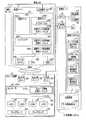
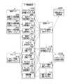
図1は、本実施形態に係る計算機システムの構成例を示す図である。
計算機システムAは、複数のストレージ装置3と、複数の物理サーバ2と、管理サーバ1とを有してなる。各ストレージ装置3および各物理サーバ2は、SAN4を介して互いに接続されている。また、各物理サーバ2と、各ストレージ装置と、管理サーバ1とは、管理LAN(Local Area Network)5を介して互いに接続されている。物理サーバ2とSAN4との接続はHBA(Host Bus Adaptor)23を経由し、ストレージ装置3とSAN4との接続はSAN用ポート35を経由して接続される。各装置1〜3における管理LAN5との接続は、LAN用ポート16,25,34を経由して接続される。"System configuration"
FIG. 1 is a diagram illustrating a configuration example of a computer system according to the present embodiment.
The computer system A includes a plurality of storage devices 3, a plurality of
(物理サーバ)
各物理サーバ2は、CPU22と、メモリ21と、デバイスファイル24と、HBA23と、LAN用ポート25とを有している。各物理サーバ2では、格納された物理サーバ性能情報取得エージェント262、ハイパバイザプログラム(以下、ハイパバイザ260と記載)、および複数の仮想マシン250がメモリ21に展開され、CPU22によって実行されることにより具現化している。デバイスファイル24については、後記する。
(Physical server)
Each
ハイパバイザ260は、各仮想マシン250が使用できるメモリ21の使用量、CPU22の使用量、デバイスファイル24へのI/O使用量を制御する機能を有するプログラムである。また、ハイパバイザ260は、仮想マシン250を他の物理サーバ2へ移動する機能も有している。ハイパバイザ260内で実行されている仮想マシン仕様情報取得エージェント261は、各仮想マシン250に割当てられたCPU割当量や、メモリ割当量などの仕様情報をハイパバイザ260から取得する機能を有するプログラムである。 The
仮想マシン250は、CPU22、メモリ21、デバイスファイル24などを仮想マシン250上で稼動するアプリケーション251などに割り当てることにより、具現化するプログラムである。仮想マシン250内で実行されているアプリケーション251は、仮想マシン250に割当てられたCPU22や、メモリ21などの計算機資源を使用して業務処理を実行する機能を有するプログラムである。また、仮想マシン250内で実行されている仮想マシン性能情報取得エージェント252は、仮想マシン250から仮想マシン250自身の性能情報を取得する機能を有するプログラムである。 The
物理サーバ性能情報取得エージェント262は、物理サーバ2自身の性能情報を取得する機能を有するプログラムである。 The physical server performance
(管理サーバ)
管理サーバ1は、CPU13と、メモリ11と、LAN用ポート16と、表示装置14と、入力装置15と、記憶装置12(記憶部)とを有している。
メモリ11には、管理プログラム110が展開され、CPU13によって実行されることにより具現化している。管理プログラム110内には、サーバI/O量変化予測プログラム111(予測値算出部)、マイグレーション先候補検索エンジン112(検索部)、ストレージ構成変更プログラム113(ストレージ構成変更部)、仮想マシン構成変更プログラム114(仮想マシン構成変更部)などの各プログラムが実行されている。管理プログラム110内で実行されている各プログラムの詳細は、後記して説明する。
記憶装置12内には、図2〜図13を参照して後記する各テーブルを保持しているデータ格納用DB(Data Base)120が格納されている。(Management server)
The
A
The
(ストレージ装置)
ストレージ装置3は、CPU36と、メモリ31と、少なくとも1つのSAN用ポート35とLAN用ポート34と、少なくとも1つのLDEV32(Logic Device)と、少なくとも1つのアレイグループ33(記憶デバイス)を有している。
メモリ31には、コントローラプログラム(以下、コントローラ311と記載)が展開され、CPU36によって実行されることにより具現化している。
ここで、コントローラ311は、複数のディスクから特定のRAID(Redundant Array of Inexpensive Disks)レベルを持つアレイグループ33を構築している。さらにコントローラ311は、アレイグループ33から指定された容量を持つ仮想ボリュームを生成する。本実施形態では、この仮想ボリュームをLDEV32と呼ぶこととする。また、コントローラ311は、LDEV32内にあるデータを別のアレイグループ33に移動する機能も有する。なお、生成されたLDEV32は、SAN用ポート35およびHBA23を経由して物理サーバ2に公開される。これにより、物理サーバ2は公開されたLDEV32をデバイスファイル24として認識することができる。(Storage device)
The storage device 3 includes a
A controller program (hereinafter referred to as a controller 311) is developed in the memory 31 and executed by the
Here, the
また、コントローラ311内には、ストレージ情報取得エージェント312が実行されている。ストレージ情報取得エージェント312は、コントローラ311より、ストレージ装置3内のLDEV32と、LDEV32を構成するアレイグループ33の性能情報を取得する機能を有するプログラムである。コントローラ311は、LDEV32と、アレイグループ33の性能情報を取得する機能も有し、ストレージ情報取得エージェント312とともに、あるLDEV32内のデータを他のLDEV32へ移動させる機能も有する。
なお、アレイグループを構成する記憶デバイスは、HD(Hard Disk)に限らず、フラッシュメモリなどを用いてもよい。In addition, a storage
The storage device constituting the array group is not limited to an HD (Hard Disk), and a flash memory or the like may be used.
《テーブル》
次に、図1を参照しつつ、図2〜図12に沿って、本実施形態に係る各テーブルについて説明する。"table"
Next, each table according to the present embodiment will be described with reference to FIGS. 2 to 12 with reference to FIG.
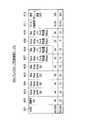
(仮想マシン性能情報テーブル)
図2は、本実施形態に係る仮想マシン性能情報テーブルの例を示す図である。
仮想マシン性能情報テーブル200は、各仮想マシン250の性能情報を格納するテーブルであり、VM(Vertual Machine)名(カラム201)、AP名(Application)(カラム202)、CPU利用率(カラム203)、メモリ利用率(カラム204)、稼働率(カラム205)、RandReadIOPS(Random Read I/O Per Second)(カラム206)、RandWriteIOPS(Random Write I/O Per Second)(カラム207)、SeqReadIOPS(Seqencial Read I/O Per Second)(カラム208)、SeqWriteIOPS(Seqencial Write I/O Per Second)(カラム209)、RandReadI/Oデータ転送量(カラム210)、SeqReadI/Oデータ転送量(カラム211)、RandWriteI/Oデータ転送量(カラム212)、SeqWriteI/Oデータ転送量(カラム213)、データ収集時刻(カラム214)を有するテーブルである。(Virtual machine performance information table)
FIG. 2 is a diagram illustrating an example of a virtual machine performance information table according to the present embodiment.
The virtual machine performance information table 200 is a table for storing performance information of each
カラム201のVM名は、対象となる仮想マシン250の名称であり、カラム202のAP名は、対象となるアプリケーション251の名称である。カラム203のCPU利用率およびカラム204のメモリ利用率は、データを収集した時刻における該当する仮想マシンに割り当てられたCPU22およびメモリ21の利用率であり、単位は「%」である。カラム205の稼働率は、仮想マシン250がデバイスファイル24(つまり、LDEV32)に対して1秒間にI/O処理を行っている割合である。 The VM name in the
ここで、「RandRead」は、ランダムリードの略であり、「RandWrite」は、ランダムライトの略であり、それぞれディスク上の連続していない領域に対するデータの書込・読込方法である。また、IOPSは、1秒あたりのディスクに対するI/O処理の回数である。つまり、カラム206のRandReadIOPS」は、仮想マシン250が、ディスクに対してランダムリードを行うとき、1秒間に処理できるI/O処理の回数であり、カラム207のRandWriteIOPSは、仮想マシン250が、ディスクに対してランダムライトを行うとき、1秒間に処理できるI/O処理の回数である。 Here, “RandRead” is an abbreviation for random read, and “RandWrite” is an abbreviation for random write, which is a method of writing / reading data to / from non-contiguous areas on the disc. IOPS is the number of I / O processes for the disk per second. In other words, “RandReadIOPS in
また、「SeqRead」は、シーケンシャルリードの略であり、「SeqWrite」は、シーケンシャルライトの略であり、それぞれディスク上の連続している領域に対するデータの書込・読込方法である。つまり、カラム208のSeqReadIOPSは、仮想マシン250が、ディスクに対してシーケンシャルリードを行うとき、1秒間に処理できるI/O処理の回数であり、カラム209のSeqWriteIOPSは、仮想マシン250が、ディスクに対してシーケンシャルライトを行うとき、1秒間に処理できるI/O処理の回数である。
なお、RandReadIOPS(カラム206)、RandWriteIOPS(カラム207)、SeqReadIOPS(カラム208)およびSeqWriteIOPS(カラム209)の単位は、「回」である。“SeqRead” is an abbreviation for sequential read, and “SeqWrite” is an abbreviation for sequential write, which is a method of writing / reading data to / from continuous areas on the disc. That is, SeqReadIOPS in
The units of RandReadIOPS (column 206), RandWriteIOPS (column 207), SeqReadIOPS (column 208), and SeqWriteIOPS (column 209) are “times”.
I/Oデータ転送量とは、1秒間にやりとりするI/Oデータの転送量を示す。つまり、カラム210のRandReadI/Oデータ転送量は、仮想マシン250が、ディスクに対してランダムリードを行うとき、1秒間にやりとりするI/Oデータの転送量であり、カラム212のRandWriteIOデータ転送量は、仮想マシン250が、ディスクに対してランダムライトを行うとき、1秒間にやりとりするI/Oデータの転送量である。 The I / O data transfer amount indicates the transfer amount of I / O data exchanged per second. That is, the RandRead I / O data transfer amount in the
同様に、カラム211のSeqReadI/Oデータ転送量は、仮想マシン250が、ディスクに対してシーケンシャルリードを行うとき、1秒間にやりとりするI/Oデータの転送量であり、カラム213のSeqWriteIOデータ転送量は、仮想マシン250が、ディスクに対してシーケンシャルライトを行うとき、1秒間にやりとりするI/Oデータの転送量である。
なお、RandReadIOデータ転送量(カラム210)、RandWriteIOデータ転送量(カラム212)、SeqReadIOデータ転送量(カラム211)およびSeqWriteIOデータ転送量(カラム213)の単位は、「Mbps」である。Similarly, the SeqRead I / O data transfer amount in the
The units of the RandReadIO data transfer amount (column 210), the RandWriteIO data transfer amount (column 212), the SeqReadIO data transfer amount (column 211), and the SeqWriteIO data transfer amount (column 213) are “Mbps”.
また、RandReadIOPS、RandWriteIOPS、SeqReadIOPSおよびSeqWriteIOPSをまとめてIOPSと適宜記載し、RandReadIOデータ転送量、RandWriteIOデータ転送量、SeqReadIOデータ転送量およびSeqWriteIOデータ転送量をまとめてIOデータ転送量と適宜記載することとする。また、IOPSおよびIOデータ転送量をまとめてIO量(入出力データ量)と適宜記載することとする。 Also, RandReadIOPS, RandWriteIOPS, SeqReadIOPS, and SeqWriteIOPS are collectively described as IOPS as appropriate, and the RandReadIO data transfer amount, RandWriteIO data transfer amount, SeqReadIO data transfer amount, and SeqWriteIO data transfer amount are collectively described as IO data transfer amount. To do. The IOPS and the IO data transfer amount are collectively described as an IO amount (input / output data amount) as appropriate.
データ収集時刻は、該当するデータを収集した時刻である。データ収集時刻は、例えば、データを収集し始めた時刻や、データを収集し終えた時刻である。 The data collection time is the time when the corresponding data is collected. The data collection time is, for example, a time when data collection is started or a time when data collection is completed.
仮想マシン250における仮想マシン性能情報取得エージェント252が、仮想マシン250毎のCPU利用率や、メモリ利用率や、各IOPS、各I/Oデータ転送量などといった性能情報を定期的に取得し、組の情報として管理サーバ1へ送る。この仮想マシン250の性能情報を受信した管理サーバ1の管理プログラム110は、受信した仮想マシン250の性能情報を、仮想マシン性能情報テーブル200の各カラム201〜214に登録することによって、仮想マシン性能情報テーブル200が生成される。 The virtual machine performance
(仮想マシン仕様情報テーブル)
図3は、本実施形態に係る仮想マシン仕様情報テーブルの例を示す図である。
仮想マシン仕様情報テーブル300は、各仮想マシン250における使用可能な最大計算機資源量を格納するテーブルであり、VM名(カラム301)、CPU割当量(カラム302)、メモリ割当量(カラム303)をカラムに有するテーブルである。
カラム301のVM名は、図2のカラム201と同様のデータであるため、説明を省略する。カラム302のCPU割当量は、該当する仮想マシン250に割当てられているCPUの最大量であり、単位は「GHz」である。カラム303のメモリ割当量は、該当する仮想マシン250に割当てられ散るメモリの最大量であり、単位は「GB」である。(Virtual machine specification information table)
FIG. 3 is a diagram illustrating an example of a virtual machine specification information table according to the present embodiment.
The virtual machine specification information table 300 is a table for storing the maximum amount of computer resources that can be used in each
The VM name in the
ハイパバイザ260における仮想マシン仕様情報取得エージェント261が、仮想マシン250毎のCPU割当量や、メモリ割当量などといった仕様情報を、新たな仮想マシン250が設定されたときに取得し、組の情報として管理サーバ1へ送る。この仮想マシン250の仕様情報を受信した管理サーバ1の管理プログラム110は、受信した仮想マシン250の仕様情報を、仮想マシン仕様情報テーブル300の各カラム301〜303に登録することによって、仮想マシン仕様情報テーブル300が生成される。 The virtual machine specification
(物理サーバ性能情報テーブル)
図4は、本実施形態に係る物理サーバ性能情報テーブルの例を示す図である。
物理サーバ性能情報テーブル400は、各物理サーバ2の性能情報を格納するテーブルであり、物理サーバ名(カラム401)、CPU利用率(カラム402)、メモリ利用率(カラム403)、稼働率(カラム404)、RandReadIOPS(カラム405)、RandWriteIOPS(カラム406)、SeqReadIOPS(カラム407)、SeqWriteIOPS(カラム408)、RandReadI/Oデータ転送量(カラム409)、SeqReadI/Oデータ転送量(カラム410)、RandWriteI/Oデータ転送量(カラム411)、SeqWriteI/Oデータ転送量(カラム412)およびデータ収集時刻(カラム413)を有するテーブルである。
カラム401の物理サーバ名は、該当する物理サーバ2の名称が格納されるカラムである。また、カラム402〜413は、図2のカラム202〜213のデータにおいて、仮想マシン250に関するデータが、物理マシンに関するデータとなったものであるため、説明を省略する。(Physical server performance information table)
FIG. 4 is a diagram showing an example of a physical server performance information table according to this embodiment.
The physical server performance information table 400 is a table that stores performance information of each
The physical server name in the
物理サーバ2における物理サーバ性能情報取得エージェント262が、物理サーバ2のCPU利用率や、メモリ利用率や、各IOPS、各I/Oデータ転送量などといった性能情報を定期的に取得し、組の情報として管理サーバ1へ送る。この物理サーバ2の性能情報を受信した管理サーバ1の管理プログラム110は、受信した物理サーバ2の性能情報を、物理サーバ性能情報テーブル400の各カラム401〜413に登録することによって、物理サーバ性能情報テーブル400が生成される。 The physical server performance
(物理サーバ仕様情報テーブル)
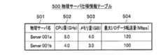
図5は、本実施形態に係る物理サーバ仕様情報テーブルの例を示す図である。
物理サーバ仕様情報テーブル500は、各物理サーバ2の仕様情報を格納したテーブルであり物理サーバ名(カラム501)、CPU量(カラム502)、メモリ量(カラム503)、最大I/Oデータ転送量(カラム504)を有する。
カラム501の物理サーバ名は、図4のカラム401と同様のデータであるため、説明を省略する。カラム502のCPU量は、該当する物理サーバ2に搭載されているCPUの性能値であり、単位は「GHz」である。カラム503のメモリ量は、該当する物理サーバ2に搭載されているメモリの性能値(容量値)であり、単位は「GB」である。カラム504の最大I/Oデータ転送量は、該当する物理サーバ2における最大のデータ転送量であり、単位は「Mbps」である。データ転送量については、前記して説明したため、ここでは説明を省略する。
物理サーバ性能情報取得エージェント262は、物理サーバ2が新たに設置されたときに、物理サーバ2から取得した物理サーバ名や、搭載されているCPUおよびメモリの性能値や、最大I/Oデータ転送量といった、物理サーバ2の仕様情報を取得すると、これらを組の情報として管理サーバ1へと送信する。管理サーバ1の管理プログラム110は、受信した物理サーバ2の仕様情報を物理サーバ仕様情報テーブル500に登録することによって、物理サーバ仕様情報テーブル500が生成される。(Physical server specification information table)
FIG. 5 is a diagram showing an example of a physical server specification information table according to the present embodiment.
The physical server specification information table 500 is a table storing the specification information of each
The physical server name in the
The physical server performance
(LDEV性能情報テーブル)
図6は、本実施形態に係るLDEV性能情報テーブルの例を示す図である。
LDEV性能情報テーブル600は、各LDEV32の性能情報を格納するテーブルであり、LDEV名(カラム601)、稼働率(カラム602)、データ収集時刻(カラム603)を有する。
カラム601のLDEV名は、各LDEV32に対し一意に付された名称である。カラム602の稼働率は、仮想マシン250が1秒間にLDEV32に対してI/O処理を行っている割合を示す値であり、単位は「%」である。カラム603のデータ収集時刻は、該当するデータを収集した時刻である。
ストレージ装置3のストレージ情報取得エージェント312は、コントローラ311から定期的に取得したLDEV名、稼働率、データ収集時刻を組とした情報を、LDEV32の性能情報として管理サーバ1へ送る。管理サーバ1の管理プログラム110が、受信したLDEV32の性能情報をLDEV性能情報テーブル600の各カラム601〜603に登録することによって、LDEV32性能テーブルが生成される。(LDEV performance information table)
FIG. 6 is a diagram showing an example of the LDEV performance information table according to the present embodiment.
The LDEV performance information table 600 is a table for storing performance information of each LDEV 32, and has an LDEV name (column 601), an operation rate (column 602), and a data collection time (column 603).
The LDEV name in the
The storage
(LDEV仕様情報テーブル)
図7は、本実施形態に係るLDEV仕様情報テーブルの例を示す図である。
LDEV仕様情報テーブル700は、各LDEV32の仕様情報を格納するテーブルであり、LDEV名(カラム701)、ボリューム容量(カラム702)、AG(Array Group)名(カラム703)を有する。
カラム701のLDEV名は、図6のカラム601のデータと同様であるため、説明を省略する。カラム702のボリューム容量は、該当するLDEV32に割り当てられたボリューム容量であり、単位は「GB」である。カラム703のAG名は、該当するLDEV32を構成するアレイグループ33の名称である。AG名は、少なくともシステム内において一意の名称である。
ストレージ装置3のストレージ情報取得エージェント312は、LDEV32が新たに設定されたときに、コントローラ311より取得したLDEV名や、LDEV32のボリューム容量や、LDEV32を構成するアレイグループ名を組とした情報をLDEV32の仕様情報として、管理サーバ1へ送る。管理サーバ1の管理プログラム110が、受信したLDEV32の使用情報をLDEV仕様情報テーブル700の各カラム701〜703に登録することにより、LDEV仕様情報テーブル700が生成される。(LDEV specification information table)
FIG. 7 is a diagram illustrating an example of the LDEV specification information table according to the present embodiment.
The LDEV specification information table 700 is a table for storing specification information of each LDEV 32, and has an LDEV name (column 701), a volume capacity (column 702), and an AG (Array Group) name (column 703).
The LDEV name in the
When the
(アレイグループ性能情報テーブル)
図8は、本実施形態に係るアレイグループ性能情報テーブルの例を示す図である。
アレイグループ性能情報テーブル800は、各アレイグループ33の性能情報を格納するテーブルであり、AG名(カラム801)、稼働率(カラム802)、RandReadIOPS(カラム803)、RandWriteIOPS(カラム804)、SeqReadIOPS(カラム805)、SeqWriteIOPS(カラム806)、RandReadI/Oデータ転送量(カラム807)、SeqReadI/Oデータ転送量(カラム808)、RandWriteI/Oデータ転送量(カラム809)、SeqWriteI/Oデータ転送量(810)、データ収集時刻(カラム811)、使用ボリューム容量(カラム812)などを有する。
カラム801のAG名は、少なくとも計算機システムA内において一意であるアレイグループ33の名称である。カラム802の稼働率は、データを収集した時刻において、該当するアレイグループ33に対して仮想マシン250が1秒間にI/O処理を行っている割合であり、単位は「%」である。
カラム803〜811は、図2のカラム206〜214における仮想マシン250におけるデータが、アレイグループ33におけるデータとなったものであるため、説明を省略する。カラム812の使用ボリューム容量は、データを収集した時刻におけるアレイグループ33のボリューム使用量であり、単位は「GB」である。(Array group performance information table)
FIG. 8 is a diagram showing an example of an array group performance information table according to this embodiment.
The array group performance information table 800 is a table for storing performance information of each
The AG name in the
Since the data in the
ストレージ装置3のストレージ情報取得エージェント312は、コントローラ311より定期的にAG名、稼働率、アレイグループ33への各IOPS、各I/Oデータ転送量、データ収集時刻、使用ボリューム容量といったデータを取得し、これらのデータを組の情報としたアレイグループ33の性能情報を管理サーバ1へ送る。管理サーバ1の管理プログラム110が、受信したアレイグループ33の性能情報をアレイグループ性能情報テーブル800の各カラム801〜812に登録することによって、アレイグループ性能情報テーブル800が生成される。 The storage
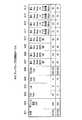
(アレイグループ仕様情報テーブル)
図9は、本実施形態に係るアレイグループ仕様情報テーブルの例を示す図である。
アレイグループ仕様情報テーブル900は、各アレイグループ33の仕様情報を格納するテーブルであり、AG名(カラム901)、ボリューム容量(カラム902)、DiskType(カラム903)、Tier(カラム904)、RAIDLevel(カラム905)、StorageType(カラム906)、最大RandReadIOPS(カラム907)、最大RandWriteIOPS(カラム908)、最大SeqReadIOPS(カラム909)、最大SeqWriteIOPS(カラム910)、最大RandReadI/Oデータ転送量(カラム911)、最大SeqReadI/Oデータ転送量(カラム912)、最大RandWriteI/Oデータ転送量(カラム913)、最大SeqWriteI/Oデータ転送量(カラム914)などを有する。(Array group specification information table)
FIG. 9 is a diagram showing an example of an array group specification information table according to the present embodiment.
The array group specification information table 900 is a table for storing the specification information of each
カラム901のAG名は、図8のカラム801と同様のデータであるため、説明を省略する。カラム902のボリューム容量は、該当するアレイグループ33におけるボリュームの容量であり、単位は「GB」である。カラム903のDiskTypeは、アレイグループ33を構成するディスクの種類であり、図9における「FC」は、Fibre Channelを示している。他に、DiskTypeとして、「SATA(Serial AT Attachment)」や、「SSD(Solid State Drive)」などの情報が入力される。 The AG name in the
カラム904のTierは、アレイグループ33の性能特性に応じて複数のアレイグループ33から優先度を示す階層を作成している場合、各アレイグループ33について階層の番号を格納するカラムである。階層番号の入力は、管理プログラム110が専用の定義GUI(Graphical User Interface)を提供し、入力データを該当するカラムに格納してもよい。なお、階層を作成すると、アクセス頻度の高いデータを高速なアレイグループ33から構成された階層に配置し、アクセス頻度のデータを低速なアレイグループ33から構成された階層に配置するなど、データの使用頻度に応じて適切にデータ配置を行うことができる。 The Tier in the
カラム905のRAID Levelは、RAIDレベルを示す。カラム906のStorage Typeは、ストレージ装置3の種類を示す。
カラム907の最大RandReadIOPSは、該当するアレイグループ33におけるRandReadIOPSの最大値である。同様に、カラム908の最大RandWriteIOPSは、該当するアレイグループ33におけるRandWriteIOPSの最大値である。カラム909の最大SeqReadIOPSは、該当するアレイグループ33におけるSeqReadIOPSの最大値である。カラム910の最大SeqWriteIOPSは、該当するアレイグループ33におけるSeqWriteIOPSの最大値である。
そして、カラム911の最大RandReadIOデータ転送量は、該当するアレイグループ33におけるRandReadIOデータ転送量の最大値である。同様に、カラム912の最大SeqReadIOデータ転送量は、該当するアレイグループ33におけるSeqReadIOデータ転送量の最大値である。カラム913の最大RandWriteIOデータ転送量は、該当するアレイグループ33におけるRandWriteIOデータ転送量の最大値である。カラム914は、最大SeqWriteIOデータ転送量は、該当するアレイグループ33におけるSeqWriteIOデータ転送量の最大値である。カラム907〜914の情報は、請求項における許容入出力データ量である。A RAID level in the
The maximum RandReadIOPS in the
The maximum RandReadIO data transfer amount in the
ストレージ装置3のストレージ情報取得エージェント312は、AG名、ボリューム容量、アレイグループ33を構成するディスクの種類、ストレージ階層を示す情報、RAIDレベル、ストレージの種類などの情報をアレイグループ33の作成時に取得すると、これらの情報を組の情報として管理サーバ1へ送る。管理サーバ1の管理プログラム110は、送られた情報を、アレイグループ仕様情報テーブル900の該当するカラム901〜906のそれぞれに登録する。
また、最大RandReadIOPS、最大SeqReadIOPS、最大RandWriteIOPS、最大SeqWriteIOPS、最大RandReadI/Oデータ転送量、最大SeqReadI/Oデータ転送量、最大RandWriteI/Oデータ転送量、最大SeqWriteI/Oデータ転送量の各情報は、例えば、管理サーバ1が、予めベンチマークテストツールを用いて各アレイグループ33について性能上限値を測定し、測定結果を取得し、アレイグループ仕様情報テーブル900の各カラム907〜914に登録する。また、性能上限値が仕様情報として公開されている場合は、ユーザが管理サーバ1の入力装置15を介して入力し、アレイグループ仕様情報テーブル900に登録してもよい。The storage
The maximum RandReadIOPS, the maximum SeqReadIOPS, the maximum RandWriteIOPS, the maximum SeqWriteIOPS, the maximum RandReadI / O data transfer amount, the maximum SeqReadI / O data transfer amount, the maximum RandWriteI / O data transfer amount, and the maximum SeqWrite I / O data transfer amount, For example, the
(経路情報テーブル)
図10は、本実施形態に係る経路情報テーブルの例を示す図である。
経路情報テーブル1000は、ある仮想マシン250が所属する物理サーバ2と、データの格納先であるLDEV32、LDEV32の所属するアレイグループ33の情報を記述するテーブルである。経路情報テーブル1000は、物理サーバ名(カラム1001)、デバイスファイル名(カラム1002)、VM名(カラム1003)、LDEV名(カラム1004)をカラムとして有する。
カラム1001の物理サーバ名は、対象となる物理サーバ2の名称である。カラム1002にデバイスファイル名は、このレコードにおけるLDEV32の情報が記述されたファイルの名称である。つまり、カラム1003における仮想マシン250がLDEV32としてアクセスするファイルの名称である。カラム1003のVM名は、仮想マシン250の名称であり、カラム1004のLDEV名は、この仮想マシン250の業務データの格納先となるLDEV32の名称である。
物理サーバ2の仮想マシン仕様情報取得エージェント261は、仮想マシン250が新たに設定されたり、LDEV32との接続が変更されたりすると、物理サーバ2の名称、仮想マシン250に割り当てられたLDEV32の名称およびこのLDEV32に関する情報が記述されているデバイスファイル24名を取得し、組の情報として管理サーバ1へ送る。管理サーバ1の仮想マシン構成変更プログラム114は、受信した情報を経路情報テーブル1000のカラム1001〜1004に登録する。(Route information table)
FIG. 10 is a diagram illustrating an example of a route information table according to the present embodiment.
The path information table 1000 is a table that describes information on the
The physical server name in the
When the
(マッピングモデルテーブル)
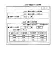
図11は、本実施形態に係るマッピングモデルテーブルの例を示す図である。
マッピングモデルテーブル1100は、物理サーバ2のスペックと仮想マシン250への割当計算機資源量の組み合わせごとに各アプリケーション251の予測性能値を格納したテーブルであり、後記する物理サーバ2移動後におけるI/O処理量の予測(図15の「予測法1」)では、このマッピングモデルテーブル1100を使用して予測を行う。
マッピングモデルテーブル1100は、AP名(カラム1101)、物理サーバCPU量(カラム1102)、物理サーバメモリ量(カラム1103)、物理サーバ空きCPU量(カラム1104)、物理サーバ空きメモリ量(カラム1105)、仮想マシンCPU消費量(カラム1106)、仮想マシンメモリ消費量(カラム1107)、予測RandReadIOPS(カラム1108)、予測RandWriteIOPS(カラム1109)、予測SeqReadIOPS(カラム1110)、予測SeqWriteIOPS(カラム1111)、予測RandReadI/Oデータ転送量(カラム1112)、予測SeqReadI/Oデータ転送量(カラム1113)、予測RandWriteI/Oデータ転送量(カラム1114)、予測SeqWriteI/Oデータ転送量(カラム1115)などの各データを有する。
各カラム内のデータについて、その取得方法とともに下記に記載する。(Mapping model table)
FIG. 11 is a diagram illustrating an example of the mapping model table according to the present embodiment.
The mapping model table 1100 is a table that stores the predicted performance value of each
The mapping model table 1100 includes an AP name (column 1101), a physical server CPU amount (column 1102), a physical server memory amount (column 1103), a physical server free CPU amount (column 1104), and a physical server free memory amount (column 1105). , Virtual machine CPU consumption (column 1106), virtual machine memory consumption (column 1107), prediction RandReadIOPS (column 1108), prediction RandWriteIOPS (column 1109), prediction SeqReadIOPS (column 1110), prediction SeqWriteIOPS (column 1111), prediction RandRead I / O data transfer amount (column 1112), predicted SeqRead I / O data transfer amount (column 1113), predicted RandWrite I / O data transfer amount (column 111) ), Having each data such as predicted SeqWriteI / O data transfer amount (column 1115).
About the data in each column, it describes below with the acquisition method.
マッピングモデルテーブル1100に登録されるデータはあらかじめベンチマークテストツールを用いて測定することができるデータである。具体的に、ベンチマークテスト時に管理サーバ1が取得するデータは、仮想マシン250を移動する移動先物理サーバと、移動する仮想マシン250と、仮想マシン250で実行されているアプリケーション251の性能情報および仕様情報である。取得した情報を元に、管理サーバ1は、ベンチマークテストを行い、その分析結果をマッピングモデルテーブル1100に書き込む。
管理プログラム110は、移動先物理サーバの物理サーバ性能情報取得エージェント262からCPU22の性能値と、メモリ21の性能値を取得し、カラム1102の物理サーバCPU量およびカラム1103の物理サーバメモリ量へ登録する。また、管理プログラム110は、移動先物理サーバの物理サーバ性能情報取得エージェント262から、移動先物理サーバにおけるCPU利用率とメモリ利用率を取得し、CPU22およびメモリ21の性能値から空きCPUと空きメモリを算出し、カラム1104の物理サーバ空きCPU量とカラム1105の物理サーバ空きメモリ量に登録する。Data registered in the mapping model table 1100 is data that can be measured in advance using a benchmark test tool. Specifically, the data acquired by the
The
さらに、管理プログラム110は、移動対象仮想マシンの仮想マシン性能情報取得エージェント252から、ベンチマークテスト結果によるCPU消費量とメモリ消費量と、ハイパバイザ260への予測RandReadIOPS、予測SeqReadIOPS、予測RandWriteIOPS、予測SeqWriteIOPSの各予測IOPSの値と、予測RandReadI/Oデータ転送量、予測SeqReadI/Oデータ転送量、予測RandWriteI/Oデータ転送量、予測SeqWriteI/Oデータ転送量の各予測I/Oデータ転送量の値を取得し、該当する各カラム1106〜1115に登録する。
なお、カラム1102〜1107が請求項における仮想マシン250に関する機器情報に相当し、カラム1108〜1115が請求項の予測入出力データ量に相当する。Further, the
Note that
(アプリケーション毎の処理量モデルテーブル)
図12は、本実施形態に係るアプリケーション毎の処理量モデルテーブルの例を示す図である。
アプリケーション251毎の処理表モデルテーブル1200は、アプリケーション251への割当計算機資源に応じたアプリケーション251の予測実行I/O量を格納するテーブルであり、後記する物理サーバ2の移動後におけるI/O処理量の予測(図16の「予測法2」)では、このアプリケーション251毎の処理表モデルテーブル1200を使用して予測を行う。
アプリケーション251毎の処理モデルテーブルは、AP名(カラム1201)、仮想マシンCPU消費量(カラム1202)、仮想マシンメモリ消費量(カラム1203)、仮想マシンI/Oデータ転送量(カラム1204)、予測RandReadIOPS(カラム1205)、予測RandWriteIOPS(カラム1206)、予測SeqReadIOPS(カラム1207)、予測SeqWriteIOPS(カラム1208)、予測RandReadI/Oデータ転送量(カラム1209)、予測SeqReadI/Oデータ転送量(カラム1210)、予測RandWriteI/Oデータ転送量(カラム1211)、予測SeqWriteI/Oデータ転送量(カラム1212)などの各データを有する。(Processing amount model table for each application)
FIG. 12 is a diagram illustrating an example of a processing amount model table for each application according to the present embodiment.
The processing table model table 1200 for each
The processing model table for each
アプリケーション251毎の処理量モデルテーブル1200に登録されるデータは、マッピングモデルテーブル1100と同じように、ベンチマークテストツールを用いて解析されたデータである。
管理サーバ1におけるベンチマークテスト時において、管理サーバ1が取得するデータは、仮想マシン250上のアプリケーション251のCPU消費量とメモリ消費量とアプリケーション251の各I/O性能情報である。Similar to the mapping model table 1100, data registered in the processing amount model table 1200 for each
The data acquired by the
アプリケーション251毎の処理モデルテーブルにおける各データについて、その取得方法とともに以下に記載する。
管理サーバ1は、各仮想マシン内の仮想マシン性能情報取得エージェント252より、各仮想マシンにおけるアプリケーション名とCPU消費量とメモリ諸費量を取得する。また、仮想マシン名を取得し、各仮想マシン250を制御するハイパバイザ260内の仮想マシン仕様情報取得エージェント261より、前記仮想マシン250のデバイスファイル24への各IOPSや、各I/Oデータ転送量などの各I/O量を取得する。
そして、管理サーバ1は、取得したI/O量を元に、ベンチマークテストを行い、その分析結果として取得した予測RandReadIOPS、予測RandWriteIOPS、予測SeqReadIOPS、予測SeqWriteIOPSの各予測IOPSの値と、予測RandReadI/Oデータ転送量、予測SeqReadI/Oデータ転送量、予測RandWriteI/Oデータ転送量、予測SeqWriteI/Oデータ転送量の各予測I/Oデータ転送量をアプリケーション251毎の処理表モデルテーブル1200における該当するカラム1205〜1212に登録する。つまり、マッピングモデルテーブル1100におけるカラム1108〜1115は、仮想マシン250が入出力するI/O量の予測値である。なお、カラム1202〜1204の情報が、請求項における仮想マシン250に関する機器情報であり、カラム1205〜カラム1212が、請求項における予測入出力データ量である。Each data in the processing model table for each
The
Then, the
《テーブル関係図》
ここで、図13を参照して、各テーブルと、各プログラムとの関係をまとめておく。
図13は、本実施形態に係るテーブル関係を示す図である。《Table relationship diagram》
Here, with reference to FIG. 13, the relationship between each table and each program is summarized.
FIG. 13 is a diagram showing a table relationship according to the present embodiment.
仮想マシン性能情報テーブル200は、物理サーバ性能情報取得エージェント262によって登録されるテーブルである。仮想マシン仕様情報テーブル300は、物理サーバ2の仮想マシン仕様情報取得エージェント261から送られるデータを用いて登録されるテーブルである。物理サーバ仕様情報テーブル500および物理サーバ性能情報テーブル400は、物理サーバ性能情報取得エージェント262から送られるデータを用いて登録されるテーブルである。LDEV仕様情報テーブル700、LDEV性能情報テーブル600およびアレイグループ性能情報テーブル800は、ストレージ装置3のストレージ情報取得エージェント312から送られるデータを用いて登録されるテーブルである。アレイグループ仕様情報テーブル900は、ベンチマークテストや、ストレージ装置3のストレージ情報取得エージェント312から送られるデータを用いて登録されるテーブルである。
経路情報テーブル1000は、物理サーバ2の物理サーバ性能情報取得エージェント262から送られるデータを用いて、仮想マシン構成変更プログラム114によって登録されるテーブルである。
また、アプリケーション251毎の処理量モデルテーブル1200およびマッピングモデルテーブル1100は、ベンチマークテストによって出力された分析結果を用いて登録されるテーブルである。The virtual machine performance information table 200 is a table registered by the physical server performance
The path information table 1000 is a table registered by the virtual machine
Further, the processing amount model table 1200 and the mapping model table 1100 for each
管理サーバ1のサーバI/O量変化予測プログラム111は、移動仮想マシン選択画面2000を介して入力された情報を基に、アプリケーション251毎の処理量モデルテーブル1200、仮想マシン性能情報テーブル200、仮想マシン仕様情報テーブル300、物理サーバ仕様情報テーブル500、物理性能情報テーブル、マッピングモデルテーブル1100などを参照して、仮想サーバの移動後におけるI/O量の変化を予測する。
そして、マイグレーション先候補検索エンジン112は、サーバI/O量変化予測プログラム111が出力した結果を使用して、LDEV仕様情報テーブル700、LDEV性能情報テーブル600、アレイグループ仕様情報テーブル900、アレイグループ性能情報テーブル800などを参照して、マイグレーション先候補を検索し、マイグレーション先候補表示画面2100に表示する。The server I / O amount
Then, the migration destination
そして、マイグレーション先候補表示画面2100で、ユーザがマイグレーション先を指定すると、ストレージ構成変更プログラム113が、LDEV仕様情報テーブル700およびLDEV性能情報テーブル600を参照して、ストレージ装置3の構成を変更し、変更結果を経路情報テーブル1000に登録する。
さらに、仮想マシン構成変更プログラム114が、ストレージ構成変更プログラム113の変更結果に従って、仮想マシン250の構成を変更し、変更結果を経路情報テーブル1000に登録する。Then, when the user designates the migration destination on the migration destination
Further, the virtual machine
《フローチャート》
次に、図1〜図12を参照しつつ、図14〜図21に沿って本実施形態に係るボリューム再配置方法の手順を説明する。"flowchart"
Next, the procedure of the volume relocation method according to this embodiment will be described with reference to FIGS. 14 to 21 with reference to FIGS.
(全体処理)
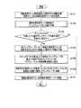
まず、図14と、図20と、図21を参照して、本実施形態に係る全体処理を説明する。
図14は、本実施形態に係る全体処理の手順の流れを示すフローチャートであり、図20は、本実施形態に係る移動仮想マシン選択画面を示す図であり、図21は、本実施形態に係るマイグレーション先候補表示画面の例を示す図である。
まず、サーバI/O量変化予測プログラム111は、図20に示す移動仮想マシン選択画面2000より選択された移動対象仮想マシン名と移動先物理サーバ名を取得する(S101)。具体的には、サーバI/O量変化予測プログラム111が、図20に示す移動仮想マシン選択画面2000を表示し、移動対象となる仮想マシン250と移動先となる物理サーバ2をユーザに入力指定してもらう。(Overall processing)
First, the overall processing according to the present embodiment will be described with reference to FIG. 14, FIG. 20, and FIG.
FIG. 14 is a flowchart showing a flow of the overall processing procedure according to the present embodiment, FIG. 20 is a diagram showing a migration virtual machine selection screen according to the present embodiment, and FIG. 21 is related to the present embodiment. It is a figure which shows the example of a migration destination candidate display screen.
First, the server I / O amount
(移動仮想マシン選択画面)
ここで、図20を参照して、移動仮想マシン選択画面について説明する。
移動仮想マシン選択画面2000は、サーバI/O量変化予測プログラム111が表示装置14に描画させる画面であり、ストレージ運用管理者による移動対象仮想マシン名と移動先物理サーバ名の選択を受け付ける画面である。
移動仮想マシン選択画面2000は、移動先物理サーバ選択領域2001と、仮想マシン選択領域2002より構成される。サーバI/O量変化予測プログラム111は、移動仮想マシン選択画面2000の移動先物理サーバ選択領域2001内の移動先物理サーバ選択リスト2011に、物理サーバ仕様情報テーブル500のカラム501に含まれる物理サーバ名の一覧をプルダウンメニューで表示する。また、サーバI/O量変化予測プログラム111は、仮想マシン選択領域2002内の仮想マシン選択リスト2021に仮想マシン仕様情報テーブル300のカラム301(VM名)に含まれる仮想マシン250名の一覧をプルダウンメニューで表示する。(Move virtual machine selection screen)
Here, the migration virtual machine selection screen will be described with reference to FIG.
The migration virtual
The migration virtual
そして、仮想マシン選択領域2002内の仮想マシン一覧リスト2022には、各仮想マシン250のリソース利用状況をリスト表示する。仮想マシン一覧リスト2022に表示する内容は、仮想マシン名、CPU使用率、メモリ使用率、ディスク使用量であり、いずれも仮想マシン性能情報テーブル200のカラム201,203〜205から取得される情報である。
実行ボタン2023が選択入力されると、サーバI/O量変化予測プログラム111は、選択された移動先物理サーバ名および仮想マシン250名を取得して、管理プログラム110は、図14のステップS102へ移行する。The virtual machine list 2022 in the virtual machine selection area 2002 displays the resource usage status of each
When the execute button 2023 is selected and input, the server I / O amount
なお、図20における移動仮想マシン選択画面2000を拡張して、移動先物理サーバ選択領域2001に、仮想マシン選択リスト2021で選択された移動対象仮想マシンのCPU割当量とメモリ割当量を設定できる領域を追加してもよい。本実施形態では、移動先物理サーバのCPUとメモリの空き資源を移動対象仮想マシンがすべて消費するように考慮しているが、このような領域を追加することで、移動先物理サーバの空き資源を有効に割当てることができる。
つまり、図20に示す画面例では説明を簡素化するため、移動する仮想マシン250に割当てるCPU使用量やメモリ量なども入力せず、移動先物理サーバの空きCPUおよび空きメモリを、すべて移動する仮想マシン250に割当てるシンプルなモデルを想定しているが、移動後に割当てるCPU使用量およびメモリ使用量を設定するよう拡張してもよい。Note that the migration virtual
That is, in order to simplify the description in the screen example shown in FIG. 20, the CPU usage amount and the memory amount allocated to the
図14の説明に戻る。
ステップS101の後、ステップS101で取得した情報を基にサーバI/O量変化予測プログラム111が移動対象仮想マシン移動後のアレイグループ33のI/O量を予測する(S102)。具体的には、サーバI/O量変化予測プログラム111は、ステップS101にて取得した移動対象仮想マシン名と移動先物理サーバ名を入力とし、各予測IOPSと各予測I/Oデータ転送量を予測I/O量として出力する(「予測法3」の場合、予測I/Oデータ転送量を出力する)。本実施形態において、予測I/O量の算出方法は、3通りであり、それぞれにおける具体的な算出方法は、図15〜図18を参照して後記するReturning to the description of FIG.
After step S101, the server I / O amount
次に、マイグレーション先候補検索エンジン112は、ステップS102で予測したI/O量が、移動対象仮想マシンのデータ格納先となるアレイグループ33の最大処理性能(最大I/O量)を上回るか否かを判定する(S103)。具体的には、マイグレーション先候補検索エンジン112が、ステップS101で取得した移動対象仮想マシン名をキーとして、経路情報テーブル1000のカラム1004を検索して、移動対象仮想マシンに接続しているLDEV名を取得する。次に、マイグレーション先候補検索エンジン112は、取得したLDEV名をキーとして、LDEV仕様情報テーブル700のカラム703(AG名)を検索して、アレイグループ名を取得する。そして、マイグレーション先候補検索エンジン112は、取得したアレイグループ名をキーとして、アレイグループ仕様情報テーブル900のカラム907〜914を検索して、最大I/O量を取得する。そした。マイグレーション先候補検索エンジン112は、この最大I/O量のうちの各最大I/Oデータ転送量の合計値が、ステップS102で算出した予測I/Oデータ転送量の合計値以上であり、かつ最大I/O量のうちの各最大IOPSの合計値が、ステップS102で算出した予測IOPSの合計値以上であるか否かを判定する。なお、予測法として、後記する「予測法3」を用いた場合、ステップS103における比較対象は、I/Oデータ転送量となる。 Next, the migration destination
ステップS103の結果、アレイグループ33の最大処理性能を上回らない場合(S103→No)、現在のアレイグループを使用しても問題ないので、管理プログラム110は、ステップS107へ処理を移行し、マイグレーションを行わずに仮想マシン250を移動する。
ステップS103の結果、アレイグループ33の最大処理性能を上回る場合(S103→Yes)、マイグレーション先候補検索エンジン112が、各アレイグループ33について移動対象の仮想マシン250が使用予定のLDEV32に移動した場合のI/O量を予測する(S104)。具体的には、マイグレーション先候補検索エンジン112は、ステップS102で算出した各予測I/O量と、アレイグループ性能情報テーブル800における現在の各アレイグループ33の各I/O量を合計することで、LDEV32をこのアレイグループ33に移動した場合の各I/O量を予測する。より具体的には、マイグレーション先候補検索エンジン112は、ステップS103の段階で取得したアレイグループ名をキーとして、アレイグループ性能情報テーブル800のカラム803〜810から現在の各I/O量を取得する。そして、マイグレーション先候補検索エンジン112は、ステップS102で取得した各予測IOデータ転送量の合計値と、取得した現在のI/O量における各IOデータ転送量の合計値を加算する。これをアレイグループにおける合計予測IOデータ転送量とする。また、マイグレーション先候補検索エンジン112は、ステップS102で取得した各予測IOPSの合計値と、取得した現在のI/O量におけるIOPSの合計値とを加算する。これをアレイグループにおける合計予測IOPSとする。As a result of step S103, if the maximum processing performance of the
When the result of step S103 exceeds the maximum processing performance of the array group 33 (S103 → Yes), the migration destination
そして、マイグレーション先候補検索エンジン112は、ステップS104で算出したアレイグループ33の予測I/O量がアレイグループ33の最大I/O量を下回るアレイグループ33のリストをマイグレーション先候補表示画面2100として表示装置14に表示させる(S105)。具体的には、マイグレーション先候補検索エンジン112は、ステップS103の段階で取得した最大I/O量のうち、各最大IOPSの合計値である合計最大IOPSと、各最大IOデータ転送量の合計値である合計最大IOデータ転送量とを算出する。そして、マイグレーション先候補検索エンジン112は、合計予測IOPSが合計最大IOPS以下であり、かつ合計予測IOデータ転送量が合計最大IOデータ転送量以下であるアレイグループ33を選択し、このアレイグループ33の一覧をマイグレーション候補表示画面として表示装置14に表示させる。 Then, the migration destination
(マイグレーション先候補表示画面)
ここで、図21を参照してマイグレーション先候補表示画面の説明を行う。
マイグレーション先候補表示画面2100は、マイグレーション先候補検索エンジン112によって表示装置14に描画される画面であり、ストレージ運用管理者からの移動先アレイグループの選択を受け付ける画面である。
マイグレーション先候補表示画面2100は、移動先アレイグループ選択領域2101より構成される。移動先アレイグループ選択領域2101内の移動先アレイグループ一覧リスト2103には、ステップS105で選択されたアレイグループ33が一覧として表示されている。移動先アレイグループ一覧リスト2103には、ステップS105で選択されたアレイグループ33の名称と、このアレイグループ名をキーとしてアレイグループ性能情報テーブル800から取得した稼働率とが表示される。そして、移動先アレイグループ選択リスト2102は、移動先アレイグループ一覧リスト2103中のアレイグループ33から1つのアレイグループ33を選択できるプルダウンメニューである。移動先アレイグループ選択リスト2102で移動先アレイグループを選択した後、実行ボタン2104が選択入力されることで、ストレージ変更プログラムは、移動先アレイグループ名を取得し、ステップS106へ処理を進める。(Migration destination candidate display screen)
Here, the migration destination candidate display screen will be described with reference to FIG.
The migration destination
The migration destination
なお、本実施形態におけるマイグレーション先候補検索エンジン112は、高速なI/O量を期待するアプリケーション251には高速のディスクを割り当て、高速なI/O量を期待しないアプリケーション251には低速なディスクを割り当てるといったアレイグループ33の階層化管理によるデータ配置の最適化の概念を取り入れた(つまり、Tierを取り入れた)ストレージ環境にそのまま採用すると、高速なI/O性能を期待しないアプリケーション251に高速なディスクを割当てる可能性がある。
そのため、前記マイグレーション先候補検索エンジン112を拡張し、LDEV32のマイグレーション先を選択する際、アレイグループ仕様情報テーブル900のカラム904(Tier)を参照し、そのLDEV32が属するTier内で移動先アレイグループを検索し、該当するアレイグループ33が存在しない場合のみ、上位のTierに含まれるアレイグループ33に移動するように拡張してもよい。The migration destination
Therefore, when the migration destination
具体的には、はじめにマイグレーション先候補検索エンジン112は移動対象仮想マシンのLDEV32が所属するアレイグループ名をLDEV仕様情報テーブル700のカラム703(AG名)から取得し、この取得したアレイグループ33名のTierに関する情報をアレイグループ仕様情報テーブル900のカラム904(Tier)から取得する。アレイグループ名の取得は、ステップS103で説明した手順と同様の手順で行われる。
ステップS105で移動先候補アレイグループをマイグレーション先候補検索エンジン112が選択する際、アレイグループ仕様情報テーブル900のカラム904(Tier)を参照し、この移動先候補アレイグループに対応するTierが、移動対象仮想マシンのLDEV32が所属するアレイグループ33のTierと一致すれば、移動先アレイグループ候補一覧リストに移動先候補アレイグループを追加する。同一のTierを有するアレイグループ33がない場合、マイグレーション先候補検索エンジン112は、1階層上のTierについて同様の処理を行う。Specifically, the migration destination
When the migration destination
図14に戻る。
ステップS105の後、ストレージ構成変更プログラム113は、ストレージ装置3内のコントローラ311に、マイグレーション先候補表示画面2100で指定された移動先アレイグループへ、移動対象仮想マシンが使用しているLDEV32のデータ内容を移動するよう指示する。そして、ストレージ装置3のコントローラ311は、移動対象仮想マシンが使用しているLDEV32の内容をマイグレーション先候補表示画面2100で選択したアレイグループ33に移動する(S106)。これと同時に、ストレージ構成変更プログラム113は、ステップS103の段階で取得している移動対象仮想マシンが使用しているLDEV名をキーとして、LDEV仕様情報テーブル700において該当するAG名(カラム703)を移動先アレイグループの名称に更新する。また、ストレージ構成変更プログラム113は、経路情報テーブル1000の移動対象仮想マシンに該当するLDEV名(カラム1004)を更新する。Returning to FIG.
After step S105, the storage
次に、仮想マシン構成変更プログラム114が、ハイパバイザ260に対して仮想マシン250をステップS101で選択した物理サーバ2へ移動するよう指示する。指示されたハイパバイザ260は、移動対象仮想マシンを移動先物理サーバへ移動する(S107)。ハイパバイザ260による仮想マシン250の移動後、仮想マシン構成変更プログラム114は、仮想マシン仕様情報取得エージェント261から送られてきた情報を基に、経路情報テーブル1000の移動対象仮想マシンが所属する物理サーバ名を更新する。Next, the virtual machine
《予測法》
次に、図1〜図12を参照しつつ、図15〜図18を参照して本実施形態に係る3つの予測法を説明する。なお、本実施形態では、それぞれの予測法を「予測法1」、「予測法2」および「予測法3」とする。また、図15〜図18における処理は、図14のステップS102に相当する処理である。
本実施形態におけるサーバI/O量変化予測プログラム111は、ストレージ運用管理者が指定した図14のステップS101にて移動対象仮想マシン名と移動先物理サーバ名を受け付け、仮想マシン250移動後のアプリケーション251のI/O量の予測を行い、予測I/O量と、移動対象仮想マシンのデータ格納先となっているアレイグループ33(現在使用中のアレイグループ33)のI/O量の合計値がアレイグループ33の最大I/O量を上回るか否かを判定する。図15〜図18では、仮想マシン250移動後のアプリケーション251のI/O量(予測I/O量)を算出する方法の詳細を示す。《Prediction method》
Next, three prediction methods according to the present embodiment will be described with reference to FIGS. 15 to 18 with reference to FIGS. In the present embodiment, the respective prediction methods are “
The server I / O amount
(予測法1)
まず、図15を参照して「予測法1」を説明する。「予測法1」は、サーバI/O量変化予測プログラム111が、移動後の物理サーバ2および仮想マシン250の仕様情報とマッピングモデル表370を用いて予測I/O量を算出する。
図15は、本実施形態に係る「予測法1」の手順の流れを示すフローチャートである。
まず、サーバI/O量変化予測プログラム111は、ステップS101において移動仮想マシン選択画面2000で選択した仮想マシン250のCPU消費量、メモリ消費量を算出する(ステップS201)。具体的には、サーバI/O量変化予測プログラム111は、ステップS101で取得した移動対象仮想マシン名をキーとして、仮想マシン仕様情報テーブル300よりCPU割当量(カラム302)とメモリ割当量(カラム303)を取得する。次に、サーバI/O量変化予測プログラム111は、ステップS101で取得した移動対象仮想マシン名をキーとして、仮想マシン性能情報テーブル200よりCPU利用率(カラム203)とメモリ利用率(カラム204)とを取得する。そして、サーバI/O量変化予測プログラム111は、取得したCPU割当量と、CPU利用率を乗算することでCPU消費量を算出し、メモリ割当量と、メモリ利用率を乗算することでメモリ消費量を算出する。(Prediction method 1)
First, “
FIG. 15 is a flowchart showing the flow of the procedure of “
First, the server I / O amount
次に、サーバI/O量変化予測プログラム111は、移動先物理サーバの空きCPU量と、空きメモリ量を算出する(S202)。具体的には、サーバI/O量変化予測プログラム111は、図14のステップS101において取得した移動先物理サーバ名をキーとして、物理サーバ性能情報テーブル400より、CPU利用率(カラム402)と、メモリ利用率(403)を取得し、さらに物理サーバ仕様情報テーブル500より、CPU量(カラム502)とメモリ量(カラム503)を取得する。そして、サーバI/O量変化予測プログラム111は、(1−CPU利用率)×CPU、および(1−メモリ利用率)×メモリを計算し、空きCPU量と、空きメモリ量を算出する。 Next, the server I / O amount
次に、サーバI/O量変化予測プログラム111は、ステップS101で取得した移動先物理サーバ名をキーとして、物理サーバ仕様情報テーブル500より、移動先物理サーバのCPU量(カラム502)とメモリ量(カラム503)を取得する(ステップS203)。なお、ステップS202の処理中で移動先物理サーバのCPU量とメモリ量を取得している場合、ステップS203の処理を行わなくてもよい。
そして、サーバI/O量変化予測プログラム111は、仮想マシン250の移動後における仮想マシン250の予測I/O量を、ステップS201、ステップS202およびステップS203で算出・取得した値とマッピングモデルテーブル1100を用いて取得する(S204)。
具体的には、サーバI/O量変化予測プログラム111は、ステップS203で取得した移動先物理サーバのCPU量およびメモリ量と、マッピングモデルテーブル1100の物理サーバCPU量(カラム1102)および物理サーバメモリ量(カラム1103)を比較する。さらに、サーバI/O量変化予測プログラム111は、ステップS202で算出した移動先物理サーバの空きCPU量および空きメモリ量と、マッピングモデルテーブル1100の物理サーバ空きCPU量(カラム1104)および物理サーバ空きメモリ量(カラム1105)とを比較する。そして、サーバI/O量変化予測プログラム111は、ステップS201で算出した移動対象仮想マシンのCPU消費量およびメモリ消費量と、マッピングモデルテーブル1100の仮想マシンCPU消費量(カラム1106)および仮想マシンメモリ消費量(カラム1107)を比較する。サーバI/O量変化予測プログラム111は、マッピングモデルテーブル1100において、これら6つの値が一致するレコードを検索し、このレコードにおける各予測I/O量(カラム1108〜1115)を取得する。Next, the server I / O amount
Then, the server I / O amount
Specifically, the server I / O amount
ここで、前記した図20の説明における移動先物理サーバ選択領域2001に、仮想マシン選択リスト2021で選択された移動対象仮想マシンのCPU割当量とメモリ割当量を設定できる領域を追加する拡張例について説明する。
このような拡張を行った場合、予測I/O量を取得するロジックに変更が生じる。具体的には、「予測法1」におけるステップS204で、マッピングモデルテーブル1100を参照する際の入力値にステップS202で算出した移動先物理サーバの空きCPU量と、空きメモリ量とを用いているが、前記した拡張を行った場合、ステップS202で算出した各値と、移動仮想マシン選択画面2000で設定したCPU割当量とメモリ割当量の値を比較し、移動仮想マシン選択画面2000で設定したCPU割当量とメモリ割当量の値が、ステップS202で算出した空きCPU量および空きメモリ量の各値未満であれば、ステップS202で算出した値の代わりに、移動仮想マシン選択画面2000で設定したCPU割当量とメモリ割当量の値をマッピングモデルテーブル1100のカラム1104(物理サーバ空きCPU量)とカラム1105(物理サーバ空きメモリ量)への入力値としてもよい。Here, an extension example in which an area in which the CPU allocation amount and the memory allocation amount of the migration target virtual machine selected in the virtual machine selection list 2021 can be set is added to the migration destination physical server selection region 2001 in the description of FIG. explain.
When such an extension is performed, a change occurs in the logic for obtaining the predicted I / O amount. Specifically, the free CPU amount and free memory amount of the destination physical server calculated in step S202 are used as input values when referring to the mapping model table 1100 in step S204 in “
「予測法1」によれば、移動後の仮想マシン250のI/O量の予測値を考慮したアレイグループ33の移動を行うことができ、仮想マシン250の移動後にI/O量が増加したことによるマイグレーションを行わずに済む。 According to “
(予測法2)
次に、図16を参照して「予測法2」を説明する。「予測法2」は、移動後の仮想マシン250への計算機資源割当量とアプリケーション251毎の処理量モデルテーブル1200を用いて仮想マシン250移動後のアプリケーション251の予測I/O量を算出する手法である。
図16は、本実施形態に係る「予測法2」の手順の流れを示すフローチャートである。
まず、サーバI/O量変化予測プログラム111は、ステップS101で選択した移動先物理サーバの空きCPU量、空きメモリ量および空き転送量を算出する(S301)具体的には、図14のステップS101で取得した移動先物理サーバ名をキーとして、物理サーバ仕様情報テーブル500よりCPU量(カラム502)、メモリ量(カラム503)および最大I/Oデータ転送量(カラム504)を取得する。また、サーバI/O量変化予測プログラム111は、図14のステップS101で取得した移動先物理サーバ名をキーとして、物理サーバ性能情報テーブル400より、CPU利用率(カラム402)、メモリ利用率(カラム403)と、各I/Oデータ転送量(カラム409〜412)を取得する。そして、サーバI/O量変化予測プログラム111が、サーバI/O量変化予測プログラム111は、(1−CPU利用率)×CPU量、(1−メモリ利用率)×メモリ量、および最大I/Oデータ転送量―各I/Oデータ転送量を算出することによって、空きCPU量、空きメモリ量、空きI/Oデータ転送量(空き転送量)を算出する。(Prediction method 2)
Next, “
FIG. 16 is a flowchart showing the flow of the procedure of “
First, the server I / O amount
次に、サーバI/O量変化予測プログラム111は、移動対象仮想マシン上のアプリケーション251に対応する全レコードをアプリケーション251毎の処理量モデルテーブル1200より取得する(S302)。具体的には、サーバI/O量変化予測プログラム111は、図14のステップS101で取得した移動対象仮想マシン名をキーとして、仮想マシン性能情報テーブル200のカラム202からアプリケーション名(AP名)を取得する。そして、サーバI/O量変化予測プログラム111は、アプリケーション251毎の処理量モデルテーブル1200において、カラム1201のAP名として取得したアプリケーション251名を有するすべてのレコードを取得する。 Next, the server I / O amount
そして、サーバI/O量変化予測プログラム111は、ステップS302で取得したレコードにステップS301の結果を適用し、レコードを特定する(S303)。具体的には、サーバI/O量変化予測プログラム111は、ステップS302で取得したレコードにおいて、ステップS301で算出した空きCPU量と空きメモリ量と空き転送量に一致する仮想マシンCPU消費量(カラム1202)、仮想マシンメモリ消費量(カラム1203)および仮想マシンI/Oデータ転送量(カラム1204)を有するレコードを特定する。
次に、サーバI/O量変化予測プログラム111は、ステップS303で特定したレコードにおける各予測IOPS(カラム1205〜1208)および予測I/Oデータ転送量(カラム1209〜1212)を取得する。Then, the server I / O amount
Next, the server I / O amount
「予測法2」によれば、「予測法1」よりも少ない情報でI/O量の予測を行うことができる。 According to “
(予測法3)
次に、図17〜図19を参照して「予測法3」を説明する。「予測法3」は、アレイグループ33のI/O量の限界を迎える前にサーバ側のCPUやメモリ、HBA23といった計算機資源の性能値が限界に達してしまい、これが原因で仮想マシン250上のアプリケーション251のI/O処理性能値が出ないと判断できる場合、サーバ側の計算機資源の性能限界に達する以前のI/O処理量の増加傾向を用いて、仮想マシン250移動後のアプリケーション251の予測I/O量を算出する手法である。
まず、図17において、予測法3を適用する前に移動先物理サーバで消費I/O量が増え得るか否かを判定する処理(「予測法3」の準備)を行い、図18において「予測法3」による予測I/O量の算出手順を説明する。
図17は、本実施形態に係る移動先物理サーバで消費I/O量が増え得るか否かを判定する手順を示すフローチャートである。
図17では、仮想マシン250が他の物理サーバ2へ移動することで移動前より多くの物理サーバ2の計算機資源を使用できるかを確認する。
まず、サーバI/O量変化予測プログラム111は、移動対象の仮想マシン250のCPU利用率、メモリ利用率および各I/Oデータ転送量を取得する(S401)。なお、このとき入力される情報が、請求項における仮想マシン250に関する機器情報である。具体的には、サーバI/O量変化予測プログラム111は、ステップS101で取得した移動対象仮想マシン名をキーとして、仮想マシン性能情報テーブル200よりCPU利用率(カラム203)、メモリ利用率(カラム204)および各I/Oデータ転送量(カラム210〜213)を取得する。
次に、サーバI/O量変化予測プログラム111は、移動先物理サーバの空きCPU量、空きメモリ量および空きI/Oデータ転送量を算出する(S402)。具体的には、サーバI/O量変化予測プログラム111が、図14のステップS101で取得した移動先物理サーバ名をキーとして、物理サーバ仕様情報テーブル500よりCPU量(カラム502)、メモリ量(カラム503)および最大I/Oデータ転送量(カラム504)を取得する。続いて、サーバI/O量変化予測プログラム111は、図14で取得した移動先物理サーバ名をキーとして、物理サーバ性能情報テーブル400より、CPU利用率(カラム402)、メモリ利用率(カラム403)および各I/Oデータ転送量(カラム409〜412)を取得する。そして、サーバI/O量変化予測プログラム111が、(1−CPU利用率)×CPU量、(1−メモリ利用率)×メモリ量、および最大I/Oデータ転送量―各I/Oデータ転送量を算出することによって、空きCPU量と空きメモリ量と空きI/Oデータ転送量を算出する。(Prediction method 3)
Next, “prediction method 3” will be described with reference to FIGS. 17 to 19. In “Prediction method 3”, the performance values of the computer resources such as the CPU and memory on the server side and the
First, in FIG. 17, before applying the prediction method 3, a process of determining whether or not the consumption I / O amount can be increased in the migration destination physical server (preparation of “prediction method 3”) is performed. A calculation procedure of the predicted I / O amount by the “prediction method 3” will be described.
FIG. 17 is a flowchart illustrating a procedure for determining whether or not the consumption I / O amount can increase in the migration destination physical server according to the present embodiment.
In FIG. 17, it is confirmed whether the
First, the server I / O amount
Next, the server I / O amount
続いて、サーバI/O量変化予測プログラム111は、ステップS403で取得した仮想マシン250の計算機資源の使用量と、ステップS402で算出した移動先物理サーバの空き計算機資源の容量をそれぞれ比較し、ステップS401で取得した計算機資源の使用量の各々が、ステップS402で算出した空き計算機資源より小さいか否かを判定する(S403)。具体的には、仮想マシン250のCPU利用率<移動先物理サーバの空きCPU量、仮想マシン250のメモリ利用率<移動先物理サーバの空きメモリ量、および仮想マシン250のI/Oデータ転送量の合計値<移動先物理サーバの空きI/Oデータ転送量といった条件のすべてが満たされるか否かを判定する Subsequently, the server I / O amount
ステップS403の結果、前記した条件の少なくとも1つが満たされない場合(S403→No)、サーバI/O量変化予測プログラム111は、ステップS401で取得した各I/Oデータ転送量を予測値(予測I/Oデータ転送量)とする(S404)。ここで、前記した条件の少なくとも1つが満たされない場合とは、少なくとも現在、仮想マシンで使用している計算機資源の1つが移動先物理サーバの空き計算機資源を上まっている状態であるため、最初からこの値を予測値とすることで、ステップS405を実行しないことにより、サーバI/O量変化予測プログラム111の処理負荷を軽減することができる。
ステップS403の結果、前記した条件のすべてが満たされる場合(S403→Yes)、サーバI/O量変化予測プログラム111が、「予測法3」を用いた各I/Oデータ転送量の予測を行う(S405)。ステップS405の処理は、図18を参照して後記する。If at least one of the above-mentioned conditions is not satisfied as a result of step S403 (S403 → No), the server I / O amount
As a result of step S403, when all of the above conditions are satisfied (S403 → Yes), the server I / O amount
図18は、本実施形態に係る「予測法3」によるI/Oデータ転送量の予測の手順を示すフローチャートであり、図19(a)は、CPU利用率の時間的変化を模式的に示したグラフであり、図19(b)は、I/O量時間的変化を模式的に示した図である。前記したように、図18の処理は図17のステップS405の処理に相当する処理である。
まず、図19(a)から説明する。
図19(a)において、横軸は時間を示し、縦軸はCPU利用率を示す。なお、図19(a)において、縦軸をCPU利用率としたが、これに限らず、メモリ利用率など計算機資源の利用率を示すものであればよい。
符号L1は、CPU利用率の変化を示す線である。図19では、時刻T1に対象となる物理サーバ2が稼動し始め、時刻T2でCPU利用率が飽和状態となっている。そして、時刻T2以降は、CPU利用率は、100%のまま推移している(時刻T3については後記する)。
図19(b)において、横軸は時間を示し、縦軸はI/Oデータ転送量を示す。P1〜Pnは、各時刻におけるI/Oデータ転送量を示している。時刻T1,T2は図19(a)と同様であり、符号I1、直線L2、破線L3および時刻T3については後記する。ここで、I/Oデータ転送量は、RandReadI/Oデータ転送量、SeqReadI/Oデータ転送量、RandWriteI/Oデータ転送量およびSeqWriteI/Oデータ転送量のいずれかであってもよいし、これらの合計値でもよい。FIG. 18 is a flowchart showing a procedure for predicting the I / O data transfer amount according to the “prediction method 3” according to the present embodiment, and FIG. 19A schematically shows a temporal change in the CPU usage rate. FIG. 19 (b) is a diagram schematically showing the I / O amount temporal change. As described above, the process in FIG. 18 corresponds to the process in step S405 in FIG.
First, FIG. 19A will be described.
In FIG. 19A, the horizontal axis indicates time, and the vertical axis indicates CPU utilization. In FIG. 19A, the vertical axis represents the CPU usage rate. However, the present invention is not limited to this, and any CPU resource usage rate such as a memory usage rate may be used.
A symbol L1 is a line indicating a change in the CPU usage rate. In FIG. 19, the target
In FIG. 19B, the horizontal axis indicates time, and the vertical axis indicates the I / O data transfer amount. P1 to Pn indicate the I / O data transfer amount at each time. Times T1 and T2 are the same as those in FIG. 19A, and reference numeral I1, straight line L2, broken line L3, and time T3 will be described later. Here, the I / O data transfer amount may be any of a RandRead I / O data transfer amount, a SeqRead I / O data transfer amount, a RandWrite I / O data transfer amount, and a SeqWrite I / O data transfer amount. It may be a total value.
ここで、図18の説明を始めると、まず、サーバI/O量変化予測プログラム111が、仮想マシン250の全計算機資源の利用率が100%でないデータ収集時間を取得する(S501)。これは、サーバI/O量変化予測プログラム111が、図14のステップS101で取得された移動対象仮想マシン名をキーとして、仮想マシン性能情報テーブル200において、CPU利用率(カラム203)や、メモリ利用率(カラム204)が100%となっていないデータ収集時刻(カラム214)を取得する。ここで、取得される時間は、図19(a)の時刻T1〜T2の直前を示す。
具体的には、サーバI/O量変化予測プログラム111が、仮想マシン性能情報テーブル200に対して次のSQL(Structured Query Language)文を実行する。Here, when the description of FIG. 18 is started, first, the server I / O amount
Specifically, the server I / O amount
Select max(データ収集時間) FROM 仮想マシン性能情報テーブル200 where CPU利用率 != 100 AND メモリ利用率 != 100 AND 稼働率 != 100Select max (data collection time) FROM virtual machine performance information table 200 where CPU utilization rate! = 100 AND memory utilization rate! = 100 AND operation rate! = 100
このようなSQL文をサーバI/O量変化予測プログラム111が実行し、データ収集時刻を取得した後、サーバI/O量変化予測プログラム111は、仮想マシン250の全計算機資源のうち一つでも100%であるデータ収集時刻を取得する(S502)。具体的には、サーバI/O量変化予測プログラム111は、図14のステップS101で取得された移動対象仮想マシン名をキーとして、仮想マシン性能情報テーブル200において、CPU利用率(カラム203)や、メモリ利用率(カラム204)が100%となっており、かつステップS501で取得したデータ収集時刻の最後の時刻の1つ後のデータ収集時刻(カラム214)を取得する。ここで、取得される時間は、図19(a)の時刻T2の直後を示す。
この処理は、サーバI/O量変化予測プログラム111が、仮想マシン性能情報テーブル200に対して、次のSQL文を実行することによって行われる。After such a SQL statement is executed by the server I / O amount
This process is performed by the server I / O amount
Select max(データ収集時間) FROM 仮想マシン性能情報テーブル200 where CPU利用率 = 100 or メモリ利用率 = 100 or 稼働率 = 100Select max (data collection time) FROM virtual machine performance information table 200 where CPU usage rate = 100 or memory usage rate = 100 or operation rate = 100
サーバI/O量変化予測プログラム111が、このSQL文を実行し、データ収集時刻を取得した後、サーバI/O量変化予測プログラム111は、ステップS501とステップS502で取得したデータ収集時刻に該当する全I/Oデータ転送量を取得する(S503)。
これは、図19の縦軸において、時刻T1〜T2の直後までの全I/Oデータ転送量に相当する(図19(b)における点P1〜Pn)。
この処理は、サーバI/O量変化予測プログラム111が、仮想マシン性能情報テーブル200に対して次のSQLを実行することによって行われる。After the server I / O amount
This corresponds to the total I / O data transfer amount immediately after time T1 to T2 on the vertical axis in FIG. 19 (points P1 to Pn in FIG. 19B).
This process is performed by the server I / O amount
Select * FROM 仮想マシン性能情報テーブル200 where データ収集時刻 BETWEEN ステップS501で取得したデータ収集時刻 AND ステップS502で取得したデータ収集時刻Select * FROM virtual machine performance information table 200 where data collection time BETWEEN data collection time acquired in step S501 AND data collection time acquired in step S502
このSQL文をサーバI/O量変化予測プログラム111は実行し全I/Oデータ転送量を取得した後、サーバI/O量変化予測プログラム111は、ステップS501およびステップS502で取得したデータ収集時刻と、各IOPSの関係式、およびステップS501およびステップS502で取得したデータ収集時刻と、各IOデータ転送量との関係式を算出する(S504)。
具体的には、ステップ802で取得したデータを元に回帰分析を行い、サーバ側の計算機資源の性能限界に達する以前のI/O処理量の増加傾向を表す関係式を算出する。ここで、算出される関係式は、図19(b)における符号L2が示す線である。
回帰分析の入力値としては、ステップS501およびステップS502で取得したデータ収集時刻と、このデータ収集時刻における各I/Oデータ転送量(図2のカラム210〜213)を用いる。
なお、本実施形態では、回帰分析を用いているが、図19(b)における点P1(一番古いI/O量)と、点Pnを単純に結んだ直線を関係式としてもよい。After this SQL statement is executed by the server I / O amount
Specifically, a regression analysis is performed based on the data acquired in
As input values for the regression analysis, the data collection times acquired in steps S501 and S502 and the respective I / O data transfer amounts (
In this embodiment, regression analysis is used. However, a straight line simply connecting the point P1 (the oldest I / O amount) and the point Pn in FIG. 19B may be used as a relational expression.
そして、サーバI/O量変化予測プログラム111は、ステップS504で算出した関係式より予測I/Oデータ転送量を算出する(S505)。
具体的には、サーバI/O量変化予測プログラム111は、仮想マシン性能情報テーブル200の最も新しい(現在から最も直近の)データ収集時刻を取得する。そして、サーバI/O量変化予測プログラム111は、取得した最も新しいデータ収集時刻を入力値として、ステップS504で算出した関係式から、当該データ収集時刻における各I/Oデータ転送量を算出する。Then, the server I / O amount
Specifically, the server I / O amount
図19(b)を参照して説明すると、最も新しいデータ収集時刻が時刻T3である。そして、算出される予測I/Oデータ転送量と、予測IOPSは、直線L2の延長線(破線L3)と、時刻T3からの垂直線の交点PxにおけるI/Oデータ転送量I1である。
サーバI/O量変化予測プログラム111は、ステップS505算出した各I/Oデータ転送量を予測I/Oデータ転送量とする。Referring to FIG. 19B, the latest data collection time is time T3. The calculated predicted I / O data transfer amount and the predicted IOPS are the I / O data transfer amount I1 at the intersection Px of the extension line of the straight line L2 (broken line L3) and the vertical line from time T3.
The server I / O amount
なお、ステップS502の処理は、省略してもよい。 Note that the process of step S502 may be omitted.
「予測法3」によれば、I/O量が限界に達する前に、サーバ側のCPUやメモリ、HBA23といった計算機資源の性能が限界に達してしまった場合にも対応できる。 According to “Prediction method 3”, it is possible to cope with the case where the performance of the computer resources such as the CPU and the memory on the server side and the
(本実施形態の別の例)
本実施形態では、移動対象仮想マシンを移動先物理サーバへ移動する際、移動先の空きCPUと空きメモリとをすべて使用した場合に予測されるI/O量に基づいてLDEV32の移動を行っている。しかし、実際に仮想マシン250の移動後、仮想マシン250上のアプリケーション251が発行するI/O量が、予測したI/O量より下回ることも予想される。そこで、前記した実施形態の別の例として、移動対象仮想マシンの移動後、定期的にI/O量を監視し、アレイグループ33の最大I/O量を上回った時に、初めて移動対象仮想マシンのデータ格納先を他のアレイグループ33に移動するようにすることもできる。(Another example of this embodiment)
In this embodiment, when the migration target virtual machine is migrated to the migration destination physical server, the
図22は、本実施形態の別の例における処理の流れを示すフローチャートである。なお、この例における計算機システムAの構成は、図1と同様であるため説明を省略する。
図22の概略を説明すると、まず、管理サーバ1およびストレージ装置3は、移動対象仮想マシンを移動先物理サーバへ移動する。このとき移動対象仮想マシンには、移動先物理サーバの空きCPUと空きメモリの資源を割り当てる。そして、仮想マシン構成変更プログラム114は、仮想マシン250の移動後、予測値に基づく制限値を設定し、移動対象仮想マシンのI/O量がこの制限値に達しているか否かを判定する。次に、移動した仮想マシン250(移動対象仮想マシン)上のアプリケーション251が発行するI/O量が、この制限したI/O量に達したことを管理サーバ1が検知したら、管理サーバ1およびストレージ装置3は、仮想マシン250のデータ格納先となっているLDEV32を他のアレイグループ33へ移動する。FIG. 22 is a flowchart showing the flow of processing in another example of the present embodiment. The configuration of the computer system A in this example is the same as that shown in FIG.
The outline of FIG. 22 will be described. First, the
以下、図22の各処理を詳細に説明する。なお、図22において前記した実施形態と同様の処理については、同一のステップ番号を付して説明を省略する。
管理サーバ1は、図14のステップS101およびステップS102の処理を行う。その後、サーバI/O量予測プログラムは、移動対象仮想マシンのデータ格納先となるアレイグループ33が処理可能であるI/O量を求め、この移動対象仮想マシンのデータ格納先となっているアレイグループ33(現在使用中のアレイグループ)の最大I/O量を超えないI/O量の制限値を決定する(S601)。具体的には、ステップS102でサーバI/O量変化予測プログラム111は、前記した「予測法1」、「予測法2」および「予測法3」のいずれかを用いて予測I/O量(「予測法3」の場合は、予測I/Oデータ転送量)を算出する。そして、サーバI/O量予測プログラムは、この予測I/O量が、データ格納先となっているアレイグループ33の最大I/O量を上回るのであれば、アレイグループ33の空きI/O量+現在の移動対象仮想マシンのI/O量の値を移動対象仮想マシンのI/O量の制限値とする。上回らないのであれば問題はないので、サーバI/O量変化予測プログラム111は制限値を設けない。Hereinafter, each process of FIG. 22 will be described in detail. In FIG. 22, processes similar to those in the above-described embodiment are denoted by the same step numbers and description thereof is omitted.
The
次に、仮想マシン構成変更プログラム114が、図14のステップS107と同様の処理を行ってステップS101で選択した移動先物理サーバに移動対象仮想マシンを移動する。
次に、仮想マシン構成変更プログラム114は、移動先物理サーバ内のハイパバイザ260に対して移動対象仮想マシンのI/O量を監視するように指示する(S602)。この機能は、予め仮想マシン構成変更プログラム114に持たせている機能である。また、仮想マシン構成変更プログラム114は、この機能に加え、ストレージポート側に対して、算出した制限値にI/O量を監視するように指示する機能を有していてもよい。このようにすることで、物理サーバ2およびストレージ装置3の双方において、I/O量を監視することができる。Next, the virtual machine
Next, the virtual machine
ステップS602指示を受けたハイパバイザ260は、監視対象の仮想マシン250(ここでは、移動後の移動対象仮想マシン)におけるI/O量を監視し、ステップS601で決定した制限値に、移動対象仮想マシンのI/O量が達したか否かを判定する(ステップS603)。
ステップS603の結果、達していない場合(S603→No)、ハイパバイザ260は、ステップS603の処理を繰り返す。
ステップS603の結果、達した場合(S603→Yes)、マイグレーション先候補検索エンジン112は、ステップS102で取得または算出した予測I/O量を移動対象仮想マシンのI/O予測値とした(S604)後、マイグレーション先候補検索エンジン112や、ストレージ構成変更プログラム113や、仮想マシン構成変更プログラム114は、図14のステップS104〜S106と同様の処理を行ってマイグレーションを実行する。そして、仮想マシン構成変更プログラム114は、移動先物理サーバ内のハイパバイザ260に対してI/O量の監視を解除するよう指示し(S605)、メモリに残っている制限値を削除する。Upon receiving the instruction in step S602, the
As a result of step S603, if not reached (S603 → No), the
If the result of step S603 is reached (S603 → Yes), the migration destination
ここでは、図22の処理は図14と独立して行われているが、図22の処理は、図14の処理後に行ってもよい。 Here, the process of FIG. 22 is performed independently of FIG. 14, but the process of FIG. 22 may be performed after the process of FIG. 14.
(効果)
本実施形態によれば、物理サーバ2内の仮想マシン250の計算機資源の再割当てを行ったときに、仮想マシン250の移動に伴うI/O量の増加を予測し、現在使用中のアレイグループ33における最大I/O量を、予測したI/O量が超える場合に、余裕のあるアレイグループ33を検索することで、仮想マシン250の移動に伴う構成変更を一度行うだけで済むようにできる。(effect)
According to the present embodiment, when the computer resources of the
A 計算機システム
1 管理サーバ
2 物理サーバ
3 ストレージ装置
4 SAN
24 デバイスファイル
32 LDEV
33 アレイグループ(記憶デバイス)
110 管理プログラム
111 I/O量変化予測プログラム(予測値算出部)
112 マイグレーション先候補検索エンジン(検索部)
113 ストレージ構成変更プログラム(ストレージ構成変更部)
114 仮想マシン構成変更プログラム(仮想マシン構成変更部)
200 仮想マシン性能情報テーブル
250 仮想マシン
252 仮想マシン性能情報取得エージェント
260 ハイパバイザ
261 仮想マシン仕様情報取得エージェント
262 物理サーバ性能情報取得エージェント
300 仮想マシン仕様情報テーブル
311 コントローラ
312 ストレージ情報取得エージェント
400 物理サーバ性能情報テーブル
500 物理サーバ仕様情報テーブル
600 LDEV性能情報テーブル
700 LDEV仕様情報テーブル
800 アレイグループ性能情報テーブル
900 アレイグループ仕様情報テーブル
1100 マッピングモデルテーブル(予測入出力データ量情報)
1200 アプリケーション毎の処理量モデルテーブル(予測入出力データ量情報)
A
24
33 Array group (storage device)
110 management program 111 I / O amount change prediction program (predicted value calculation unit)
112 Migration destination candidate search engine (search unit)
113 Storage configuration change program (storage configuration change unit)
114 Virtual machine configuration change program (virtual machine configuration change unit)
200 Virtual Machine Performance Information Table 250
1200 Processing amount model table for each application (predicted input / output data amount information)
Claims (15)
Translated fromJapanese前記管理サーバは、
記憶部にストレージ装置における記憶デバイスの許容入出力データ量に関する許容入出力情報が記憶されており、
前記管理サーバが、
現在仮想マシンが搭載されている物理サーバから、入力部を介して、あらかじめ選択されている他の前記物理サーバへ当該仮想マシンを移動する際に、
移動する前記仮想マシンに関する機器情報を取得し、
前記取得した機器情報を基に、移動後の仮想マシンにおける予測される入出力データ量である予測入出力データ量の算出を行い、
前記算出された予測入出力データ量が、前記仮想マシンがアクセス可能な記憶デバイスにおける許容入出力データ量以上である場合、前記許容入出力データ量が、前記予測入出力データ量を下回る記憶デバイスを検索し、
前記検索した記憶デバイスと、移動する仮想マシンを関連付けた後、
前記移動する仮想マシンを、他の物理サーバへ移動する
ことを特徴とするストレージ管理方法。A computer having a virtual machine running on a physical server and a storage device, and further comprising a management server for managing the association between the virtual machine and the physical server and the association between the virtual machine and the storage device A storage management method in a system,
The management server
The storage unit stores allowable input / output information related to the allowable input / output data amount of the storage device in the storage device,
The management server is
When moving the virtual machine from the physical server on which the virtual machine is currently mounted to another physical server selected in advance via the input unit,
Obtain device information about the virtual machine to be moved,
Based on the acquired device information, calculate the predicted input / output data amount that is the predicted input / output data amount in the virtual machine after movement,
When the calculated predicted input / output data amount is equal to or larger than the allowable input / output data amount in the storage device accessible by the virtual machine, the storage device in which the allowable input / output data amount is lower than the predicted input / output data amount. Search
After associating the searched storage device with the virtual machine to be moved,
A storage management method, wherein the moving virtual machine is moved to another physical server.
前記管理サーバが
移動する仮想マシンおよび移動先の物理サーバにおける機器情報を基に、前記予測入出力データ量情報から、対応する前記予測入出力データ量を取得することによって、前記予測入出力データ量の算出を行う
ことを特徴とする請求項1に記載のストレージ管理方法In the storage unit, a plurality of predicted input / output data amounts in the virtual machine after movement are stored in correspondence with the physical server and the device information of the virtual machine as device information related to the virtual machine I / O data volume information is stored,
The predicted input / output data amount is obtained by acquiring the corresponding predicted input / output data amount from the predicted input / output data amount information based on the device information in the virtual machine to which the management server is moved and the physical server of the transfer destination. The storage management method according to claim 1, wherein the storage management method is calculated.
前記管理サーバが、
移動する仮想マシンにおけるアプリケーションおよび当該移動する仮想マシンの機器情報を基に、前記予測入出力データ量情報から、対応する前記予測入出力データ量を取得することによって、前記予測入出力データ量の算出を行うことを特徴とする
ことを特徴とする請求項1に記載のストレージ管理方法。In the storage unit, a plurality of predicted input / output data amounts in the virtual machine after the movement are stored corresponding to the application information as the device information related to the virtual machine and the device information of the virtual machine using the application The predicted input / output data amount information is stored,
The management server is
Calculation of the predicted input / output data amount by acquiring the corresponding predicted input / output data amount from the predicted input / output data amount information based on the application in the moving virtual machine and the device information of the moving virtual machine The storage management method according to claim 1, wherein the storage management method is performed.
前記管理サーバが、
移動前の前記仮想マシンを実行している物理サーバにおける前記過去の機器情報が、当該機器情報の機器の性能の限界値を超えていない限界値未満である時間を取得し、
前記取得した時間における前記過去の入出力データ量を取得し、
前記取得した過去の入出力データ量における、前記時間との関係式を算出し、
前記関係式を基に、所定の時間における入出力データ量を算出し、
当該算出した入出力データ量を、前記予測入出力データ量とする
ことを特徴とする請求項1に記載のストレージ管理方法。The storage unit stores past device information and past input / output data amounts related to the moving virtual machine,
The management server is
Obtain the time when the past device information in the physical server that is executing the virtual machine before movement is less than the limit value that does not exceed the device performance limit value of the device information,
Obtaining the past input / output data amount at the obtained time;
In the acquired past input / output data amount, a relational expression with the time is calculated,
Based on the relational expression, the input / output data amount at a predetermined time is calculated,
The storage management method according to claim 1, wherein the calculated input / output data amount is the predicted input / output data amount.
前記管理サーバは、
前記許容入出力データ量が、前記予測入出力データ量を下回る記憶デバイスを検索する際に、当該記憶デバイスが所属する階層におけるストレージ装置で検索を行い、当該階層におけるストレージ装置で、前記予測入出力データ量を下回る記憶デバイスが検出できなかった場合、上位の階層に属すストレージ装置を検索する
ことを特徴とする請求項1に記載のストレージ管理方法。The storage device has a hierarchical structure between the storage devices,
The management server
When searching for a storage device in which the allowable input / output data amount is less than the predicted input / output data amount, the storage device in the tier to which the storage device belongs is searched, and the predicted input / output in the storage device in the tier The storage management method according to claim 1, wherein when a storage device having a data amount less than the data amount cannot be detected, a storage device belonging to an upper tier is searched.
ことを特徴とする請求項1に記載のストレージ管理方法。The storage management method according to claim 1, wherein a CPU allocation amount and a memory allocation amount in the migration destination physical server of the virtual machine can be set via an input / output unit.
前記予測入出力データ量を基に、前記仮想マシンが使用している記憶デバイスにおける入出力データの制限値を設定し、
前記物理サーバによる前記仮想マシンの移動後、
前記仮想マシンの入出力データ量を監視しており、
前記仮想マシンの入出力データ量が、前記制限値を超えた場合、前記許容入出力データ量が、前記予測入出力データ量を下回る記憶デバイスを検索する
ことを特徴とする請求項1に記載のストレージ管理方法。The management server is
Based on the predicted input / output data amount, set a limit value of input / output data in the storage device used by the virtual machine,
After moving the virtual machine by the physical server,
Monitoring the amount of input and output data of the virtual machine,
The storage device in which the allowable input / output data amount falls below the predicted input / output data amount when the input / output data amount of the virtual machine exceeds the limit value. Storage management method.
前記仮想マシンの入出力データ量に加え、前記ストレージ装置のポートにおける入出力データ量も監視する
ことを特徴とする請求項7に記載のストレージ管理方法。The management server is
The storage management method according to claim 7, wherein, in addition to the input / output data amount of the virtual machine, the input / output data amount at the port of the storage apparatus is also monitored.
ストレージ装置における記憶デバイスの許容入出力データ量に関する許容入出力情報が記憶されている記憶部と、
現在仮想マシンが搭載されている物理サーバから、入力部を介して、あらかじめ選択されている他の前記物理サーバへ当該仮想マシンを移動する際に、移動する前記仮想マシンに関する機器情報を取得し、前記取得した機器情報を基に、移動後の仮想マシンにおける予測される入出力データ量である予測入出力データ量の算出を行う予測値算出部と、
前記算出された予測入出力データ量が、前記仮想マシンがアクセス可能な記憶デバイスにおける許容入出力データ量以上である場合、前記許容入出力データ量が、前記予測入出力データ量を下回る記憶デバイスを検索する検索部と、
前記検索した記憶デバイスと、移動する仮想マシンを関連付けるストレージ構成変更部と、
前記移動する仮想マシンを、他の物理サーバへ移動する仮想マシン構成変更部と、
を有することを特徴とする管理サーバ。A management server that manages association between a virtual machine and a physical server, and association between the virtual machine and a storage device;
A storage unit storing allowable input / output information related to the allowable input / output data amount of the storage device in the storage device;
When moving the virtual machine from the physical server on which the virtual machine is currently mounted to the other physical server selected in advance via the input unit, obtain device information about the virtual machine to be moved, Based on the acquired device information, a predicted value calculation unit that calculates a predicted input / output data amount that is a predicted input / output data amount in the virtual machine after movement,
When the calculated predicted input / output data amount is equal to or larger than the allowable input / output data amount in the storage device accessible by the virtual machine, the storage device in which the allowable input / output data amount is lower than the predicted input / output data amount. A search part to search;
A storage configuration change unit for associating the searched storage device with a virtual machine to be moved;
A virtual machine configuration changing unit for moving the virtual machine to be moved to another physical server;
A management server characterized by comprising:
前記予測値算出部は、
移動する仮想マシンおよび移動先の物理サーバにおける機器情報を基に、前記予測入出力データ量情報から、対応する前記予測入出力データ量を取得することによって、前記予測入出力データ量の算出を行う
ことを特徴とする請求項9に記載の管理サーバ。In the storage unit, the predicted input / output data amount in the virtual machine after movement is stored in correspondence with the physical server and the device information of the virtual machine as the device information related to the virtual machine. Data volume information is stored,
The predicted value calculation unit
The predicted input / output data amount is calculated by obtaining the corresponding predicted input / output data amount from the predicted input / output data amount information based on the device information in the virtual machine to be moved and the physical server of the movement destination. The management server according to claim 9.
前記予測値算出部は、
移動する仮想マシンにおけるアプリケーションおよび当該移動する仮想マシンの機器情報を基に、前記予測入出力データ量情報から、対応する前記予測入出力データ量を取得することによって、前記予測入出力データ量の算出を行う機能を
さらに有することを特徴とする請求項9に記載の管理サーバ。In the storage unit, the predicted input / output data amount in the virtual machine after movement is stored in correspondence with the application information as the device information related to the virtual machine and the device information of the virtual machine using the application. The predicted input / output data volume information is stored,
The predicted value calculation unit
Calculation of the predicted input / output data amount by acquiring the corresponding predicted input / output data amount from the predicted input / output data amount information based on the application in the moving virtual machine and the device information of the moving virtual machine The management server according to claim 9, further comprising a function of performing the following.
前記予測値算出部は、
移動前の前記仮想マシンを実行している物理サーバにおける前記過去の機器情報が、当該機器情報の機器の性能の限界値を超えていない限界値未満である時間の取得、前記取得した時間における前記過去の入出力データ量の取得、前記取得した過去の入出力データ量における、前記時間との関係式の算出、お前記関係式を基にした所定の時間における入出力データ量の算出、および当該算出した入出力データ量を、前記予測入出力データ量とする機能を
さらに有することを特徴とする請求項9に記載の管理サーバ。The storage unit stores past device information and past input / output data amounts related to the moving virtual machine,
The predicted value calculation unit
Acquisition of the time when the past device information in the physical server that is executing the virtual machine before movement is less than the limit value that does not exceed the limit value of the device performance of the device information, the time at the acquired time Acquisition of past input / output data amount, calculation of relational expression with time in the acquired past input / output data amount, calculation of input / output data amount at predetermined time based on the relational expression, and The management server according to claim 9, further comprising a function of setting the calculated input / output data amount as the predicted input / output data amount.
前記検索部は、
前記記許容入出力データ量が、前記予測入出力データ量を下回る記憶デバイスを検索する際に、当該記憶デバイスが所属する階層におけるストレージ装置で検索を行い、当該階層におけるストレージ装置で、前記予測入出力データ量を下回る記憶デバイスが検出できなかった場合、上位の階層に属すストレージ装置を検索する機能を
さらに有することを特徴とする請求項9に記載の管理サーバ。The storage device has a hierarchical structure between the storage devices, and the search unit
When searching for a storage device whose allowable input / output data amount is less than the predicted input / output data amount, the storage device in the tier to which the storage device belongs is searched, and the storage device in the tier The management server according to claim 9, further comprising a function of searching for a storage device belonging to an upper tier when a storage device having a lower output data amount cannot be detected.
ことを特徴とする請求項9に記載の管理サーバ。The management server according to claim 9, wherein a CPU allocation amount and a memory allocation amount in the migration destination physical server of the virtual machine can be set via an input / output unit.
前記予測入出力データ量を基に、前記仮想マシンが使用している記憶デバイスにおける入出力データの制限値を設定する機能を
さらに備え
前記検索部は、
前記物理サーバによる前記仮想マシンの移動後、前記仮想マシンの入出力データ量を監視し、前記仮想マシンの入出力データ量が、前記制限値を超えた場合、前記許容入出力データ量が、前記予測入出力データ量を下回る記憶デバイスを検索する機能を
さらに有することを特徴とする請求項9に記載の管理サーバ。
The predicted value calculation unit
Based on the predicted input / output data amount, the search unit further includes a function of setting a limit value of input / output data in the storage device used by the virtual machine.
After the virtual machine is moved by the physical server, the input / output data amount of the virtual machine is monitored, and if the input / output data amount of the virtual machine exceeds the limit value, the allowable input / output data amount is The management server according to claim 9, further comprising a function of searching for a storage device that is less than the predicted input / output data amount.
Priority Applications (2)
| Application Number | Priority Date | Filing Date | Title |
|---|---|---|---|
| JP2008282267AJP2010108409A (en) | 2008-10-31 | 2008-10-31 | Storage management method and management server |
| US12/352,854US8122116B2 (en) | 2008-10-31 | 2009-01-13 | Storage management method and management server |
Applications Claiming Priority (1)
| Application Number | Priority Date | Filing Date | Title |
|---|---|---|---|
| JP2008282267AJP2010108409A (en) | 2008-10-31 | 2008-10-31 | Storage management method and management server |
Publications (1)
| Publication Number | Publication Date |
|---|---|
| JP2010108409Atrue JP2010108409A (en) | 2010-05-13 |
Family
ID=42132816
Family Applications (1)
| Application Number | Title | Priority Date | Filing Date |
|---|---|---|---|
| JP2008282267APendingJP2010108409A (en) | 2008-10-31 | 2008-10-31 | Storage management method and management server |
Country Status (2)
| Country | Link |
|---|---|
| US (1) | US8122116B2 (en) |
| JP (1) | JP2010108409A (en) |
Cited By (17)
| Publication number | Priority date | Publication date | Assignee | Title |
|---|---|---|---|---|
| JP2012093842A (en)* | 2010-10-25 | 2012-05-17 | Sanken Electric Co Ltd | Power supply device and program |
| WO2012120664A1 (en)* | 2011-03-09 | 2012-09-13 | 株式会社日立製作所 | Virtual machine migration evaluation method and virtual machine system |
| JP2012226427A (en)* | 2011-04-15 | 2012-11-15 | Hitachi Ltd | Resource management method and computer system |
| JP2013069214A (en)* | 2011-09-26 | 2013-04-18 | Fujitsu Ltd | Storage system |
| WO2013061375A1 (en) | 2011-10-27 | 2013-05-02 | Hitachi, Ltd. | Storage system and its management method |
| JP2013093053A (en)* | 2010-08-09 | 2013-05-16 | Sanken Electric Co Ltd | Power-supply unit, program, and control method |
| WO2013108386A1 (en)* | 2012-01-19 | 2013-07-25 | 株式会社日立製作所 | Method for managing computer system, computer system, and storage medium |
| JP2013206103A (en)* | 2012-03-28 | 2013-10-07 | Nec Corp | Virtualization system, host computer for management, firmware update method for storage system and firmware update program for storage system |
| EP2648127A1 (en) | 2012-03-29 | 2013-10-09 | Fujitsu Limited | Access control method, server device, and storage device |
| JP2014063324A (en)* | 2012-09-20 | 2014-04-10 | Fujitsu Ltd | Information processing method, information processor, and program |
| WO2014199586A1 (en)* | 2013-06-12 | 2014-12-18 | International Business Machines Corporation | Implementing capacity and user-based resource allocation for a shared adapter in a virtualized system |
| JP2015534663A (en)* | 2012-08-14 | 2015-12-03 | アルカテル−ルーセント | Method and apparatus for providing a traffic RE aware slot arrangement |
| JP2016045682A (en)* | 2014-08-22 | 2016-04-04 | 日本電信電話株式会社 | server |
| WO2016121005A1 (en)* | 2015-01-27 | 2016-08-04 | 株式会社日立製作所 | Management computer and computer system management method |
| WO2017216891A1 (en)* | 2016-06-15 | 2017-12-21 | 株式会社日立製作所 | Computer system, control method for computer system, and program |
| KR101816718B1 (en) | 2016-09-22 | 2018-02-22 | 고려대학교 산학협력단 | The system for CPU Network integrated scheduling and the controlling method thereof |
| JP2019021315A (en)* | 2017-07-19 | 2019-02-07 | 三星電子株式会社Samsung Electronics Co.,Ltd. | System for performing auto tearing, method thereof, and recording medium on which instruction word for execution is recorded |
Families Citing this family (80)
| Publication number | Priority date | Publication date | Assignee | Title |
|---|---|---|---|---|
| US7675854B2 (en) | 2006-02-21 | 2010-03-09 | A10 Networks, Inc. | System and method for an adaptive TCP SYN cookie with time validation |
| US8099487B1 (en)* | 2006-07-06 | 2012-01-17 | Netapp, Inc. | Systems and methods for determining placement of virtual machines |
| US8312507B2 (en) | 2006-10-17 | 2012-11-13 | A10 Networks, Inc. | System and method to apply network traffic policy to an application session |
| US8584199B1 (en) | 2006-10-17 | 2013-11-12 | A10 Networks, Inc. | System and method to apply a packet routing policy to an application session |
| JP5476764B2 (en)* | 2009-03-30 | 2014-04-23 | 富士通株式会社 | Server apparatus, computer system, program, and virtual computer migration method |
| US8359594B1 (en)* | 2009-06-30 | 2013-01-22 | Sychron Advanced Technologies, Inc. | Automated rapid virtual machine provisioning system |
| KR101644569B1 (en)* | 2009-10-01 | 2016-08-01 | 삼성전자 주식회사 | Apparatus and method for managing virtual processing unit |
| US20120198063A1 (en)* | 2009-10-09 | 2012-08-02 | Nec Corporation | Virtual server system, autonomous control server thereof, and data processing method and computer program thereof |
| US8301860B2 (en)* | 2009-10-16 | 2012-10-30 | International Business Machines Corporation | Identifying dynamically changing virtual storage devices |
| US9960967B2 (en) | 2009-10-21 | 2018-05-01 | A10 Networks, Inc. | Determining an application delivery server based on geo-location information |
| US8245140B2 (en)* | 2009-12-31 | 2012-08-14 | International Business Machines Corporation | Visualization and consolidation of virtual machines in a virtualized data center |
| US9135031B1 (en)* | 2010-04-28 | 2015-09-15 | Netapp, Inc. | System and method for determining storage resources of a virtual machine in a virtual server environment |
| US9215275B2 (en) | 2010-09-30 | 2015-12-15 | A10 Networks, Inc. | System and method to balance servers based on server load status |
| US8489827B2 (en)* | 2010-10-28 | 2013-07-16 | Hewlett-Packard Development Company, L.P. | Method and system for storage-system management |
| US9253016B2 (en) | 2010-11-02 | 2016-02-02 | International Business Machines Corporation | Management of a data network of a computing environment |
| US8984109B2 (en) | 2010-11-02 | 2015-03-17 | International Business Machines Corporation | Ensemble having one or more computing systems and a controller thereof |
| US8959220B2 (en) | 2010-11-02 | 2015-02-17 | International Business Machines Corporation | Managing a workload of a plurality of virtual servers of a computing environment |
| US9081613B2 (en) | 2010-11-02 | 2015-07-14 | International Business Machines Corporation | Unified resource manager providing a single point of control |
| US8966020B2 (en) | 2010-11-02 | 2015-02-24 | International Business Machines Corporation | Integration of heterogeneous computing systems into a hybrid computing system |
| EP2458501A1 (en)* | 2010-11-30 | 2012-05-30 | France Telecom | Method of operating a communication device and related communication device |
| US9609052B2 (en) | 2010-12-02 | 2017-03-28 | A10 Networks, Inc. | Distributing application traffic to servers based on dynamic service response time |
| US8863138B2 (en)* | 2010-12-22 | 2014-10-14 | Intel Corporation | Application service performance in cloud computing |
| US8897154B2 (en) | 2011-10-24 | 2014-11-25 | A10 Networks, Inc. | Combining stateless and stateful server load balancing |
| US9386088B2 (en) | 2011-11-29 | 2016-07-05 | A10 Networks, Inc. | Accelerating service processing using fast path TCP |
| US9094364B2 (en) | 2011-12-23 | 2015-07-28 | A10 Networks, Inc. | Methods to manage services over a service gateway |
| US10044582B2 (en) | 2012-01-28 | 2018-08-07 | A10 Networks, Inc. | Generating secure name records |
| US8838887B1 (en)* | 2012-03-30 | 2014-09-16 | Emc Corporation | Drive partitioning for automated storage tiering |
| US9503517B1 (en)* | 2012-05-07 | 2016-11-22 | Amazon Technologies, Inc. | Data volume placement techniques |
| US9348724B2 (en)* | 2012-05-21 | 2016-05-24 | Hitachi, Ltd. | Method and apparatus for maintaining a workload service level on a converged platform |
| US8959383B2 (en)* | 2012-06-13 | 2015-02-17 | Microsoft Corporation | Failover estimation using contradiction |
| US8782221B2 (en)* | 2012-07-05 | 2014-07-15 | A10 Networks, Inc. | Method to allocate buffer for TCP proxy session based on dynamic network conditions |
| US10019287B1 (en)* | 2012-08-23 | 2018-07-10 | Scale Computing | Virtual machine resource display |
| US10021174B2 (en) | 2012-09-25 | 2018-07-10 | A10 Networks, Inc. | Distributing service sessions |
| US9843484B2 (en) | 2012-09-25 | 2017-12-12 | A10 Networks, Inc. | Graceful scaling in software driven networks |
| KR101692751B1 (en) | 2012-09-25 | 2017-01-04 | 에이10 네트워크스, 인코포레이티드 | Load distribution in data networks |
| US10002141B2 (en) | 2012-09-25 | 2018-06-19 | A10 Networks, Inc. | Distributed database in software driven networks |
| GB2506623A (en)* | 2012-10-04 | 2014-04-09 | Ibm | Managing user files in a tiered storage system |
| US20140122825A1 (en)* | 2012-10-30 | 2014-05-01 | Hitachi, Ltd. | Computer system and method for updating configuration information |
| US9338225B2 (en) | 2012-12-06 | 2016-05-10 | A10 Networks, Inc. | Forwarding policies on a virtual service network |
| US9208051B2 (en)* | 2012-12-26 | 2015-12-08 | Bmc Software, Inc. | Automatic creation of graph time layer of model of computer network objects and relationships |
| US9531846B2 (en) | 2013-01-23 | 2016-12-27 | A10 Networks, Inc. | Reducing buffer usage for TCP proxy session based on delayed acknowledgement |
| US9900252B2 (en) | 2013-03-08 | 2018-02-20 | A10 Networks, Inc. | Application delivery controller and global server load balancer |
| WO2014144837A1 (en) | 2013-03-15 | 2014-09-18 | A10 Networks, Inc. | Processing data packets using a policy based network path |
| US10038693B2 (en) | 2013-05-03 | 2018-07-31 | A10 Networks, Inc. | Facilitating secure network traffic by an application delivery controller |
| US10027761B2 (en) | 2013-05-03 | 2018-07-17 | A10 Networks, Inc. | Facilitating a secure 3 party network session by a network device |
| US9317317B2 (en) | 2013-06-12 | 2016-04-19 | International Business Machines Corporation | Implementing concurrent device driver maintenance and recovery for an SRIOV adapter in a virtualized system |
| US9323620B2 (en) | 2013-06-12 | 2016-04-26 | International Business Machines Corporation | Implementing shared adapter configuration updates concurrent with maintenance actions in a virtualized system |
| US9720775B2 (en) | 2013-06-12 | 2017-08-01 | International Business Machines Corporation | Implementing concurrent adapter firmware update for an SRIOV adapter in a virtualized system |
| US9400704B2 (en) | 2013-06-12 | 2016-07-26 | Globalfoundries Inc. | Implementing distributed debug data collection and analysis for a shared adapter in a virtualized system |
| US9304849B2 (en) | 2013-06-12 | 2016-04-05 | International Business Machines Corporation | Implementing enhanced error handling of a shared adapter in a virtualized system |
| US10230770B2 (en) | 2013-12-02 | 2019-03-12 | A10 Networks, Inc. | Network proxy layer for policy-based application proxies |
| JP6194016B2 (en)* | 2013-12-06 | 2017-09-06 | 株式会社日立製作所 | Computer and load measuring method |
| US9817683B2 (en)* | 2014-01-10 | 2017-11-14 | Dell Products, Lp | Optimized remediation policy in a virtualized environment |
| US10020979B1 (en) | 2014-03-25 | 2018-07-10 | A10 Networks, Inc. | Allocating resources in multi-core computing environments |
| US9942152B2 (en) | 2014-03-25 | 2018-04-10 | A10 Networks, Inc. | Forwarding data packets using a service-based forwarding policy |
| US9942162B2 (en) | 2014-03-31 | 2018-04-10 | A10 Networks, Inc. | Active application response delay time |
| US9052938B1 (en) | 2014-04-15 | 2015-06-09 | Splunk Inc. | Correlation and associated display of virtual machine data and storage performance data |
| US9806943B2 (en) | 2014-04-24 | 2017-10-31 | A10 Networks, Inc. | Enabling planned upgrade/downgrade of network devices without impacting network sessions |
| US9906422B2 (en) | 2014-05-16 | 2018-02-27 | A10 Networks, Inc. | Distributed system to determine a server's health |
| US10129122B2 (en) | 2014-06-03 | 2018-11-13 | A10 Networks, Inc. | User defined objects for network devices |
| US9992229B2 (en) | 2014-06-03 | 2018-06-05 | A10 Networks, Inc. | Programming a data network device using user defined scripts with licenses |
| US9986061B2 (en) | 2014-06-03 | 2018-05-29 | A10 Networks, Inc. | Programming a data network device using user defined scripts |
| US10430219B2 (en)* | 2014-06-06 | 2019-10-01 | Yokogawa Electric Corporation | Configuring virtual machines in a cloud computing platform |
| US9286104B1 (en)* | 2015-01-05 | 2016-03-15 | International Business Machines Corporation | Selecting virtual machines to be relocated based on memory volatility |
| US11336519B1 (en)* | 2015-03-10 | 2022-05-17 | Amazon Technologies, Inc. | Evaluating placement configurations for distributed resource placement |
| US10581976B2 (en) | 2015-08-12 | 2020-03-03 | A10 Networks, Inc. | Transmission control of protocol state exchange for dynamic stateful service insertion |
| US10243791B2 (en) | 2015-08-13 | 2019-03-26 | A10 Networks, Inc. | Automated adjustment of subscriber policies |
| US10318288B2 (en) | 2016-01-13 | 2019-06-11 | A10 Networks, Inc. | System and method to process a chain of network applications |
| US10440153B1 (en)* | 2016-02-08 | 2019-10-08 | Microstrategy Incorporated | Enterprise health score and data migration |
| US10713072B1 (en)* | 2016-06-27 | 2020-07-14 | Amazon Technologies, Inc. | Computing resource provisioning |
| US10389835B2 (en) | 2017-01-10 | 2019-08-20 | A10 Networks, Inc. | Application aware systems and methods to process user loadable network applications |
| US10540202B1 (en)* | 2017-09-28 | 2020-01-21 | EMC IP Holding Company LLC | Transient sharing of available SAN compute capability |
| US10795598B1 (en) | 2017-12-07 | 2020-10-06 | Pure Storage, Inc. | Volume migration for storage systems synchronously replicating a dataset |
| US10776173B1 (en) | 2018-04-30 | 2020-09-15 | Amazon Technologies, Inc. | Local placement of resource instances in a distributed system |
| JP6842447B2 (en)* | 2018-09-12 | 2021-03-17 | 株式会社日立製作所 | Systems and methods to help optimize resource allocation |
| US11637748B2 (en) | 2019-08-28 | 2023-04-25 | Microstrategy Incorporated | Self-optimization of computing environments |
| US11210189B2 (en) | 2019-08-30 | 2021-12-28 | Microstrategy Incorporated | Monitoring performance of computing systems |
| US11360881B2 (en) | 2019-09-23 | 2022-06-14 | Microstrategy Incorporated | Customizing computer performance tests |
| CN115437739A (en)* | 2021-06-02 | 2022-12-06 | 伊姆西Ip控股有限责任公司 | Resource management method of virtualization system, electronic device and computer program product |
| US12106153B2 (en)* | 2021-06-30 | 2024-10-01 | Salesforce, Inc. | Tenant-level monitoring |
Citations (7)
| Publication number | Priority date | Publication date | Assignee | Title |
|---|---|---|---|---|
| JP2004199561A (en)* | 2002-12-20 | 2004-07-15 | Hitachi Ltd | Computer resource allocation method, resource management server and computer system for executing the method |
| JP2006164169A (en)* | 2004-12-10 | 2006-06-22 | Hitachi Ltd | Network storage system of cluster configuration sharing name space and control method thereof |
| JP2006228188A (en)* | 2005-02-14 | 2006-08-31 | Hitachi Ltd | How to dynamically balance storage system load |
| JP2007094473A (en)* | 2005-09-27 | 2007-04-12 | Hitachi Ltd | File system migration in storage systems |
| JP2007148469A (en)* | 2005-11-24 | 2007-06-14 | Hitachi Ltd | Prior resource allocation method using business process definition |
| JP2007280099A (en)* | 2006-04-07 | 2007-10-25 | Hitachi Ltd | System and method for performing directory unit migration in a common namespace |
| US20080270564A1 (en)* | 2007-04-25 | 2008-10-30 | Microsoft Corporation | Virtual machine migration |
Family Cites Families (15)
| Publication number | Priority date | Publication date | Assignee | Title |
|---|---|---|---|---|
| US6802062B1 (en)* | 1997-04-01 | 2004-10-05 | Hitachi, Ltd. | System with virtual machine movable between virtual machine systems and control method |
| US6480862B1 (en)* | 1999-04-23 | 2002-11-12 | International Business Machines Corporation | Relation-based ordering of objects in an object heap |
| JP2005234834A (en)* | 2004-02-19 | 2005-09-02 | Hitachi Ltd | Relocation method of logical volume |
| US7886299B2 (en) | 2004-06-01 | 2011-02-08 | Hitachi, Ltd. | Method of dynamically balancing workload of a storage system |
| CA2486103A1 (en)* | 2004-10-26 | 2006-04-26 | Platespin Ltd. | System and method for autonomic optimization of physical and virtual resource use in a data center |
| US7607129B2 (en)* | 2005-04-07 | 2009-10-20 | International Business Machines Corporation | Method and apparatus for using virtual machine technology for managing parallel communicating applications |
| JP4775846B2 (en)* | 2006-03-20 | 2011-09-21 | 株式会社日立製作所 | Computer system and method for controlling allocation of physical links |
| US8291411B2 (en)* | 2007-05-21 | 2012-10-16 | International Business Machines Corporation | Dynamic placement of virtual machines for managing violations of service level agreements (SLAs) |
| US7966614B2 (en)* | 2007-07-24 | 2011-06-21 | International Business Machines Corporation | Controlling an availability policy for a virtual machine based on changes in a real world environment |
| US8880797B2 (en)* | 2007-09-05 | 2014-11-04 | Emc Corporation | De-duplication in a virtualized server environment |
| US8191063B2 (en)* | 2007-09-30 | 2012-05-29 | Symantex Corporation | Method for migrating a plurality of virtual machines by associating files and state information with a single logical container |
| US8015232B2 (en)* | 2007-10-11 | 2011-09-06 | Roaming Keyboards Llc | Thin terminal computer architecture utilizing roaming keyboard files |
| US20090150700A1 (en)* | 2007-12-06 | 2009-06-11 | International Business Machines Corporation | Method of controlling power to a plurality of servers |
| JP4894745B2 (en)* | 2007-12-14 | 2012-03-14 | 富士通株式会社 | Virtual machine migration control method |
| JP5223596B2 (en)* | 2008-10-30 | 2013-06-26 | 富士通株式会社 | Virtual computer system and management method thereof, management program, recording medium, and control method |
- 2008
- 2008-10-31JPJP2008282267Apatent/JP2010108409A/enactivePending
- 2009
- 2009-01-13USUS12/352,854patent/US8122116B2/ennot_activeExpired - Fee Related
Patent Citations (8)
| Publication number | Priority date | Publication date | Assignee | Title |
|---|---|---|---|---|
| JP2004199561A (en)* | 2002-12-20 | 2004-07-15 | Hitachi Ltd | Computer resource allocation method, resource management server and computer system for executing the method |
| JP2006164169A (en)* | 2004-12-10 | 2006-06-22 | Hitachi Ltd | Network storage system of cluster configuration sharing name space and control method thereof |
| JP2006228188A (en)* | 2005-02-14 | 2006-08-31 | Hitachi Ltd | How to dynamically balance storage system load |
| JP2007094473A (en)* | 2005-09-27 | 2007-04-12 | Hitachi Ltd | File system migration in storage systems |
| JP2007148469A (en)* | 2005-11-24 | 2007-06-14 | Hitachi Ltd | Prior resource allocation method using business process definition |
| JP2007280099A (en)* | 2006-04-07 | 2007-10-25 | Hitachi Ltd | System and method for performing directory unit migration in a common namespace |
| US20080270564A1 (en)* | 2007-04-25 | 2008-10-30 | Microsoft Corporation | Virtual machine migration |
| JP2010527056A (en)* | 2007-04-25 | 2010-08-05 | マイクロソフト コーポレーション | Virtual machine migration |
Cited By (25)
| Publication number | Priority date | Publication date | Assignee | Title |
|---|---|---|---|---|
| JP2013093053A (en)* | 2010-08-09 | 2013-05-16 | Sanken Electric Co Ltd | Power-supply unit, program, and control method |
| JP2012093842A (en)* | 2010-10-25 | 2012-05-17 | Sanken Electric Co Ltd | Power supply device and program |
| WO2012120664A1 (en)* | 2011-03-09 | 2012-09-13 | 株式会社日立製作所 | Virtual machine migration evaluation method and virtual machine system |
| JPWO2012120664A1 (en)* | 2011-03-09 | 2014-07-07 | 株式会社日立製作所 | Virtual machine migration evaluation method and virtual machine system |
| JP2012226427A (en)* | 2011-04-15 | 2012-11-15 | Hitachi Ltd | Resource management method and computer system |
| JP2013069214A (en)* | 2011-09-26 | 2013-04-18 | Fujitsu Ltd | Storage system |
| US8578178B2 (en) | 2011-10-27 | 2013-11-05 | Hitachi, Ltd. | Storage system and its management method |
| WO2013061375A1 (en) | 2011-10-27 | 2013-05-02 | Hitachi, Ltd. | Storage system and its management method |
| US9400761B2 (en) | 2012-01-19 | 2016-07-26 | Hitachi, Ltd. | Management method for computer system, computer system, and non-transitory computer-readable storage medium |
| WO2013108386A1 (en)* | 2012-01-19 | 2013-07-25 | 株式会社日立製作所 | Method for managing computer system, computer system, and storage medium |
| JPWO2013108386A1 (en)* | 2012-01-19 | 2015-05-11 | 株式会社日立製作所 | Computer system management method, computer system, and storage medium |
| JP2013206103A (en)* | 2012-03-28 | 2013-10-07 | Nec Corp | Virtualization system, host computer for management, firmware update method for storage system and firmware update program for storage system |
| US9276824B2 (en) | 2012-03-29 | 2016-03-01 | Fujitsu Limited | Access control method, server device, and storage device |
| EP2648127A1 (en) | 2012-03-29 | 2013-10-09 | Fujitsu Limited | Access control method, server device, and storage device |
| JP2015534663A (en)* | 2012-08-14 | 2015-12-03 | アルカテル−ルーセント | Method and apparatus for providing a traffic RE aware slot arrangement |
| US9378032B2 (en) | 2012-09-20 | 2016-06-28 | Fujitsu Limited | Information processing method, information processing apparatus, recording medium, and system |
| JP2014063324A (en)* | 2012-09-20 | 2014-04-10 | Fujitsu Ltd | Information processing method, information processor, and program |
| WO2014199586A1 (en)* | 2013-06-12 | 2014-12-18 | International Business Machines Corporation | Implementing capacity and user-based resource allocation for a shared adapter in a virtualized system |
| JP2016045682A (en)* | 2014-08-22 | 2016-04-04 | 日本電信電話株式会社 | server |
| WO2016121005A1 (en)* | 2015-01-27 | 2016-08-04 | 株式会社日立製作所 | Management computer and computer system management method |
| WO2017216891A1 (en)* | 2016-06-15 | 2017-12-21 | 株式会社日立製作所 | Computer system, control method for computer system, and program |
| JPWO2017216891A1 (en)* | 2016-06-15 | 2018-12-06 | 株式会社日立製作所 | Computer system, computer system control method, and program |
| KR101816718B1 (en) | 2016-09-22 | 2018-02-22 | 고려대학교 산학협력단 | The system for CPU Network integrated scheduling and the controlling method thereof |
| JP2019021315A (en)* | 2017-07-19 | 2019-02-07 | 三星電子株式会社Samsung Electronics Co.,Ltd. | System for performing auto tearing, method thereof, and recording medium on which instruction word for execution is recorded |
| JP7063756B2 (en) | 2017-07-19 | 2022-05-09 | 三星電子株式会社 | A recording medium on which the system for performing auto-tearing, its method, and the command words for execution are recorded. |
Also Published As
| Publication number | Publication date |
|---|---|
| US8122116B2 (en) | 2012-02-21 |
| US20100115049A1 (en) | 2010-05-06 |
Similar Documents
| Publication | Publication Date | Title |
|---|---|---|
| JP2010108409A (en) | Storage management method and management server | |
| JP4749140B2 (en) | Data migration method and system | |
| US8694727B2 (en) | First storage control apparatus and storage system management method | |
| JP5123641B2 (en) | Performance history management method and performance history management system | |
| JP4631301B2 (en) | Cache management method for storage device | |
| JP5117120B2 (en) | Computer system, method and program for managing volume of storage device | |
| JP5395962B2 (en) | Computer system, management method thereof, and program | |
| JP5502232B2 (en) | Storage system and control method thereof | |
| CN102473134B (en) | Management server, management method, and management program for virtual hard disk | |
| US8549528B2 (en) | Arrangements identifying related resources having correlation with selected resource based upon a detected performance status | |
| JP5781925B2 (en) | Computer system and control method thereof | |
| JP4885575B2 (en) | Storage area allocation optimization method and management computer for realizing the method | |
| US9354914B2 (en) | Storage system | |
| US20120311260A1 (en) | Storage managing system, computer system, and storage managing method | |
| WO2011052005A1 (en) | Storage controller and storage control method for dynamically assigning partial areas of pool area as data storage areas | |
| US20100125715A1 (en) | Storage System and Operation Method Thereof | |
| JP2008108020A (en) | Computer system, data migration method, and storage management server | |
| CN101364164A (en) | Storage System | |
| JP2005038071A (en) | Management methods to optimize storage capacity | |
| JP2007058637A (en) | Storage system, management computer and data migration method | |
| JP2007140728A (en) | Storage device system and storage control method | |
| JP2012003694A (en) | Storage controller, storage control method and storage system | |
| US20080109630A1 (en) | Storage system, storage unit, and storage management system | |
| JP5183363B2 (en) | Logical volume data migration method, storage system, and management computer | |
| US20140058717A1 (en) | Simulation system for simulating i/o performance of volume and simulation method |
Legal Events
| Date | Code | Title | Description |
|---|---|---|---|
| A621 | Written request for application examination | Free format text:JAPANESE INTERMEDIATE CODE: A621 Effective date:20100217 | |
| A977 | Report on retrieval | Free format text:JAPANESE INTERMEDIATE CODE: A971007 Effective date:20100820 | |
| A131 | Notification of reasons for refusal | Free format text:JAPANESE INTERMEDIATE CODE: A131 Effective date:20100831 | |
| A521 | Request for written amendment filed | Free format text:JAPANESE INTERMEDIATE CODE: A523 Effective date:20101029 | |
| A02 | Decision of refusal | Free format text:JAPANESE INTERMEDIATE CODE: A02 Effective date:20101207 |