JP2010104764A - System and method for vertebral interbody fusion - Google Patents
System and method for vertebral interbody fusionDownload PDFInfo
- Publication number
- JP2010104764A JP2010104764AJP2009084504AJP2009084504AJP2010104764AJP 2010104764 AJP2010104764 AJP 2010104764AJP 2009084504 AJP2009084504 AJP 2009084504AJP 2009084504 AJP2009084504 AJP 2009084504AJP 2010104764 AJP2010104764 AJP 2010104764A
- Authority
- JP
- Japan
- Prior art keywords
- inserter
- fusion cage
- collet
- opening
- locking sleeve
- Prior art date
- Legal status (The legal status is an assumption and is not a legal conclusion. Google has not performed a legal analysis and makes no representation as to the accuracy of the status listed.)
- Pending
Links
- 230000004927fusionEffects0.000titleclaimsabstractdescription142
- 238000000034methodMethods0.000titleclaimsdescription31
- 238000003780insertionMethods0.000claimsdescription38
- 230000037431insertionEffects0.000claimsdescription38
- 239000000463materialSubstances0.000claimsdescription11
- 230000007246mechanismEffects0.000claimsdescription7
- 210000000988bone and boneAnatomy0.000claimsdescription6
- 230000008468bone growthEffects0.000claimsdescription4
- 230000002188osteogenic effectEffects0.000claimsdescription4
- 230000004913activationEffects0.000claimsdescription2
- 239000000126substanceSubstances0.000claimsdescription2
- 229910045601alloyInorganic materials0.000description4
- 239000000956alloySubstances0.000description4
- 238000001356surgical procedureMethods0.000description3
- 239000004696Poly ether ether ketoneSubstances0.000description2
- 230000001276controlling effectEffects0.000description2
- 230000007423decreaseEffects0.000description2
- 239000003102growth factorSubstances0.000description2
- 230000013011matingEffects0.000description2
- 229910052751metalInorganic materials0.000description2
- 239000002184metalSubstances0.000description2
- 229920002530polyetherether ketonePolymers0.000description2
- 230000002028prematureEffects0.000description2
- 229920000049Carbon (fiber)Polymers0.000description1
- 229910000684Cobalt-chromeInorganic materials0.000description1
- RTAQQCXQSZGOHL-UHFFFAOYSA-NTitaniumChemical compound[Ti]RTAQQCXQSZGOHL-UHFFFAOYSA-N0.000description1
- WAIPAZQMEIHHTJ-UHFFFAOYSA-N[Cr].[Co]Chemical compound[Cr].[Co]WAIPAZQMEIHHTJ-UHFFFAOYSA-N0.000description1
- 230000009471actionEffects0.000description1
- 238000013459approachMethods0.000description1
- 239000000560biocompatible materialSubstances0.000description1
- 210000002805bone matrixAnatomy0.000description1
- 239000001506calcium phosphateSubstances0.000description1
- 239000004917carbon fiberSubstances0.000description1
- 239000000919ceramicSubstances0.000description1
- 239000010952cobalt-chromeSubstances0.000description1
- 238000004891communicationMethods0.000description1
- 230000008878couplingEffects0.000description1
- 238000010168coupling processMethods0.000description1
- 238000005859coupling reactionMethods0.000description1
- 239000012634fragmentSubstances0.000description1
- 229910052588hydroxylapatiteInorganic materials0.000description1
- 239000003550markerSubstances0.000description1
- 150000002739metalsChemical class0.000description1
- VNWKTOKETHGBQD-UHFFFAOYSA-NmethaneChemical compoundCVNWKTOKETHGBQD-UHFFFAOYSA-N0.000description1
- 230000004048modificationEffects0.000description1
- 238000012986modificationMethods0.000description1
- XYJRXVWERLGGKC-UHFFFAOYSA-Dpentacalcium;hydroxide;triphosphateChemical compound[OH-].[Ca+2].[Ca+2].[Ca+2].[Ca+2].[Ca+2].[O-]P([O-])([O-])=O.[O-]P([O-])([O-])=O.[O-]P([O-])([O-])=OXYJRXVWERLGGKC-UHFFFAOYSA-D0.000description1
- 239000004033plasticSubstances0.000description1
- 229920003023plasticPolymers0.000description1
- 229920002635polyurethanePolymers0.000description1
- 239000004814polyurethaneSubstances0.000description1
- 238000002601radiographyMethods0.000description1
- 230000001105regulatory effectEffects0.000description1
- 239000011347resinSubstances0.000description1
- 229920005989resinPolymers0.000description1
- 239000010935stainless steelSubstances0.000description1
- 229910001220stainless steelInorganic materials0.000description1
- GUVRBAGPIYLISA-UHFFFAOYSA-Ntantalum atomChemical compound[Ta]GUVRBAGPIYLISA-UHFFFAOYSA-N0.000description1
- 239000010936titaniumSubstances0.000description1
- 229910052719titaniumInorganic materials0.000description1
- QORWJWZARLRLPR-UHFFFAOYSA-Htricalcium bis(phosphate)Chemical compound[Ca+2].[Ca+2].[Ca+2].[O-]P([O-])([O-])=O.[O-]P([O-])([O-])=OQORWJWZARLRLPR-UHFFFAOYSA-H0.000description1
- 229940078499tricalcium phosphateDrugs0.000description1
- 229910000391tricalcium phosphateInorganic materials0.000description1
- 235000019731tricalcium phosphateNutrition0.000description1
- 238000003466weldingMethods0.000description1
Images


Classifications
- A—HUMAN NECESSITIES
- A61—MEDICAL OR VETERINARY SCIENCE; HYGIENE
- A61F—FILTERS IMPLANTABLE INTO BLOOD VESSELS; PROSTHESES; DEVICES PROVIDING PATENCY TO, OR PREVENTING COLLAPSING OF, TUBULAR STRUCTURES OF THE BODY, e.g. STENTS; ORTHOPAEDIC, NURSING OR CONTRACEPTIVE DEVICES; FOMENTATION; TREATMENT OR PROTECTION OF EYES OR EARS; BANDAGES, DRESSINGS OR ABSORBENT PADS; FIRST-AID KITS
- A61F2/00—Filters implantable into blood vessels; Prostheses, i.e. artificial substitutes or replacements for parts of the body; Appliances for connecting them with the body; Devices providing patency to, or preventing collapsing of, tubular structures of the body, e.g. stents
- A61F2/02—Prostheses implantable into the body
- A61F2/30—Joints
- A61F2/44—Joints for the spine, e.g. vertebrae, spinal discs
- A61F2/4455—Joints for the spine, e.g. vertebrae, spinal discs for the fusion of spinal bodies, e.g. intervertebral fusion of adjacent spinal bodies, e.g. fusion cages
- A61F2/447—Joints for the spine, e.g. vertebrae, spinal discs for the fusion of spinal bodies, e.g. intervertebral fusion of adjacent spinal bodies, e.g. fusion cages substantially parallelepipedal, e.g. having a rectangular or trapezoidal cross-section
- A—HUMAN NECESSITIES
- A61—MEDICAL OR VETERINARY SCIENCE; HYGIENE
- A61F—FILTERS IMPLANTABLE INTO BLOOD VESSELS; PROSTHESES; DEVICES PROVIDING PATENCY TO, OR PREVENTING COLLAPSING OF, TUBULAR STRUCTURES OF THE BODY, e.g. STENTS; ORTHOPAEDIC, NURSING OR CONTRACEPTIVE DEVICES; FOMENTATION; TREATMENT OR PROTECTION OF EYES OR EARS; BANDAGES, DRESSINGS OR ABSORBENT PADS; FIRST-AID KITS
- A61F2/00—Filters implantable into blood vessels; Prostheses, i.e. artificial substitutes or replacements for parts of the body; Appliances for connecting them with the body; Devices providing patency to, or preventing collapsing of, tubular structures of the body, e.g. stents
- A61F2/02—Prostheses implantable into the body
- A61F2/30—Joints
- A61F2/46—Special tools for implanting artificial joints
- A61F2/4603—Special tools for implanting artificial joints for insertion or extraction of endoprosthetic joints or of accessories thereof
- A61F2/4611—Special tools for implanting artificial joints for insertion or extraction of endoprosthetic joints or of accessories thereof of spinal prostheses
- A—HUMAN NECESSITIES
- A61—MEDICAL OR VETERINARY SCIENCE; HYGIENE
- A61F—FILTERS IMPLANTABLE INTO BLOOD VESSELS; PROSTHESES; DEVICES PROVIDING PATENCY TO, OR PREVENTING COLLAPSING OF, TUBULAR STRUCTURES OF THE BODY, e.g. STENTS; ORTHOPAEDIC, NURSING OR CONTRACEPTIVE DEVICES; FOMENTATION; TREATMENT OR PROTECTION OF EYES OR EARS; BANDAGES, DRESSINGS OR ABSORBENT PADS; FIRST-AID KITS
- A61F2/00—Filters implantable into blood vessels; Prostheses, i.e. artificial substitutes or replacements for parts of the body; Appliances for connecting them with the body; Devices providing patency to, or preventing collapsing of, tubular structures of the body, e.g. stents
- A61F2/02—Prostheses implantable into the body
- A61F2/30—Joints
- A61F2/3094—Designing or manufacturing processes
- A61F2/30965—Reinforcing the prosthesis by embedding particles or fibres during moulding or dipping
- A—HUMAN NECESSITIES
- A61—MEDICAL OR VETERINARY SCIENCE; HYGIENE
- A61F—FILTERS IMPLANTABLE INTO BLOOD VESSELS; PROSTHESES; DEVICES PROVIDING PATENCY TO, OR PREVENTING COLLAPSING OF, TUBULAR STRUCTURES OF THE BODY, e.g. STENTS; ORTHOPAEDIC, NURSING OR CONTRACEPTIVE DEVICES; FOMENTATION; TREATMENT OR PROTECTION OF EYES OR EARS; BANDAGES, DRESSINGS OR ABSORBENT PADS; FIRST-AID KITS
- A61F2/00—Filters implantable into blood vessels; Prostheses, i.e. artificial substitutes or replacements for parts of the body; Appliances for connecting them with the body; Devices providing patency to, or preventing collapsing of, tubular structures of the body, e.g. stents
- A61F2/02—Prostheses implantable into the body
- A61F2/28—Bones
- A61F2002/2835—Bone graft implants for filling a bony defect or an endoprosthesis cavity, e.g. by synthetic material or biological material
- A—HUMAN NECESSITIES
- A61—MEDICAL OR VETERINARY SCIENCE; HYGIENE
- A61F—FILTERS IMPLANTABLE INTO BLOOD VESSELS; PROSTHESES; DEVICES PROVIDING PATENCY TO, OR PREVENTING COLLAPSING OF, TUBULAR STRUCTURES OF THE BODY, e.g. STENTS; ORTHOPAEDIC, NURSING OR CONTRACEPTIVE DEVICES; FOMENTATION; TREATMENT OR PROTECTION OF EYES OR EARS; BANDAGES, DRESSINGS OR ABSORBENT PADS; FIRST-AID KITS
- A61F2/00—Filters implantable into blood vessels; Prostheses, i.e. artificial substitutes or replacements for parts of the body; Appliances for connecting them with the body; Devices providing patency to, or preventing collapsing of, tubular structures of the body, e.g. stents
- A61F2/02—Prostheses implantable into the body
- A61F2/30—Joints
- A61F2002/30001—Additional features of subject-matter classified in A61F2/28, A61F2/30 and subgroups thereof
- A61F2002/30003—Material related properties of the prosthesis or of a coating on the prosthesis
- A61F2002/3006—Properties of materials and coating materials
- A61F2002/3008—Properties of materials and coating materials radio-opaque, e.g. radio-opaque markers
- A—HUMAN NECESSITIES
- A61—MEDICAL OR VETERINARY SCIENCE; HYGIENE
- A61F—FILTERS IMPLANTABLE INTO BLOOD VESSELS; PROSTHESES; DEVICES PROVIDING PATENCY TO, OR PREVENTING COLLAPSING OF, TUBULAR STRUCTURES OF THE BODY, e.g. STENTS; ORTHOPAEDIC, NURSING OR CONTRACEPTIVE DEVICES; FOMENTATION; TREATMENT OR PROTECTION OF EYES OR EARS; BANDAGES, DRESSINGS OR ABSORBENT PADS; FIRST-AID KITS
- A61F2/00—Filters implantable into blood vessels; Prostheses, i.e. artificial substitutes or replacements for parts of the body; Appliances for connecting them with the body; Devices providing patency to, or preventing collapsing of, tubular structures of the body, e.g. stents
- A61F2/02—Prostheses implantable into the body
- A61F2/30—Joints
- A61F2002/30001—Additional features of subject-matter classified in A61F2/28, A61F2/30 and subgroups thereof
- A61F2002/30316—The prosthesis having different structural features at different locations within the same prosthesis; Connections between prosthetic parts; Special structural features of bone or joint prostheses not otherwise provided for
- A61F2002/30535—Special structural features of bone or joint prostheses not otherwise provided for
- A61F2002/30593—Special structural features of bone or joint prostheses not otherwise provided for hollow
- A—HUMAN NECESSITIES
- A61—MEDICAL OR VETERINARY SCIENCE; HYGIENE
- A61F—FILTERS IMPLANTABLE INTO BLOOD VESSELS; PROSTHESES; DEVICES PROVIDING PATENCY TO, OR PREVENTING COLLAPSING OF, TUBULAR STRUCTURES OF THE BODY, e.g. STENTS; ORTHOPAEDIC, NURSING OR CONTRACEPTIVE DEVICES; FOMENTATION; TREATMENT OR PROTECTION OF EYES OR EARS; BANDAGES, DRESSINGS OR ABSORBENT PADS; FIRST-AID KITS
- A61F2/00—Filters implantable into blood vessels; Prostheses, i.e. artificial substitutes or replacements for parts of the body; Appliances for connecting them with the body; Devices providing patency to, or preventing collapsing of, tubular structures of the body, e.g. stents
- A61F2/02—Prostheses implantable into the body
- A61F2/30—Joints
- A61F2/30767—Special external or bone-contacting surface, e.g. coating for improving bone ingrowth
- A61F2/30771—Special external or bone-contacting surface, e.g. coating for improving bone ingrowth applied in original prostheses, e.g. holes or grooves
- A61F2002/30772—Apertures or holes, e.g. of circular cross section
- A61F2002/30784—Plurality of holes
- A61F2002/30785—Plurality of holes parallel
- A—HUMAN NECESSITIES
- A61—MEDICAL OR VETERINARY SCIENCE; HYGIENE
- A61F—FILTERS IMPLANTABLE INTO BLOOD VESSELS; PROSTHESES; DEVICES PROVIDING PATENCY TO, OR PREVENTING COLLAPSING OF, TUBULAR STRUCTURES OF THE BODY, e.g. STENTS; ORTHOPAEDIC, NURSING OR CONTRACEPTIVE DEVICES; FOMENTATION; TREATMENT OR PROTECTION OF EYES OR EARS; BANDAGES, DRESSINGS OR ABSORBENT PADS; FIRST-AID KITS
- A61F2/00—Filters implantable into blood vessels; Prostheses, i.e. artificial substitutes or replacements for parts of the body; Appliances for connecting them with the body; Devices providing patency to, or preventing collapsing of, tubular structures of the body, e.g. stents
- A61F2/02—Prostheses implantable into the body
- A61F2/30—Joints
- A61F2/30767—Special external or bone-contacting surface, e.g. coating for improving bone ingrowth
- A61F2/30771—Special external or bone-contacting surface, e.g. coating for improving bone ingrowth applied in original prostheses, e.g. holes or grooves
- A61F2002/30772—Apertures or holes, e.g. of circular cross section
- A61F2002/3079—Stepped or enlarged apertures, e.g. having discrete diameter changes
- A—HUMAN NECESSITIES
- A61—MEDICAL OR VETERINARY SCIENCE; HYGIENE
- A61F—FILTERS IMPLANTABLE INTO BLOOD VESSELS; PROSTHESES; DEVICES PROVIDING PATENCY TO, OR PREVENTING COLLAPSING OF, TUBULAR STRUCTURES OF THE BODY, e.g. STENTS; ORTHOPAEDIC, NURSING OR CONTRACEPTIVE DEVICES; FOMENTATION; TREATMENT OR PROTECTION OF EYES OR EARS; BANDAGES, DRESSINGS OR ABSORBENT PADS; FIRST-AID KITS
- A61F2/00—Filters implantable into blood vessels; Prostheses, i.e. artificial substitutes or replacements for parts of the body; Appliances for connecting them with the body; Devices providing patency to, or preventing collapsing of, tubular structures of the body, e.g. stents
- A61F2/02—Prostheses implantable into the body
- A61F2/30—Joints
- A61F2/30767—Special external or bone-contacting surface, e.g. coating for improving bone ingrowth
- A61F2/30771—Special external or bone-contacting surface, e.g. coating for improving bone ingrowth applied in original prostheses, e.g. holes or grooves
- A61F2002/30904—Special external or bone-contacting surface, e.g. coating for improving bone ingrowth applied in original prostheses, e.g. holes or grooves serrated profile, i.e. saw-toothed
- A—HUMAN NECESSITIES
- A61—MEDICAL OR VETERINARY SCIENCE; HYGIENE
- A61F—FILTERS IMPLANTABLE INTO BLOOD VESSELS; PROSTHESES; DEVICES PROVIDING PATENCY TO, OR PREVENTING COLLAPSING OF, TUBULAR STRUCTURES OF THE BODY, e.g. STENTS; ORTHOPAEDIC, NURSING OR CONTRACEPTIVE DEVICES; FOMENTATION; TREATMENT OR PROTECTION OF EYES OR EARS; BANDAGES, DRESSINGS OR ABSORBENT PADS; FIRST-AID KITS
- A61F2/00—Filters implantable into blood vessels; Prostheses, i.e. artificial substitutes or replacements for parts of the body; Appliances for connecting them with the body; Devices providing patency to, or preventing collapsing of, tubular structures of the body, e.g. stents
- A61F2/02—Prostheses implantable into the body
- A61F2/30—Joints
- A61F2/30767—Special external or bone-contacting surface, e.g. coating for improving bone ingrowth
- A61F2002/3092—Special external or bone-contacting surface, e.g. coating for improving bone ingrowth having an open-celled or open-pored structure
- A—HUMAN NECESSITIES
- A61—MEDICAL OR VETERINARY SCIENCE; HYGIENE
- A61F—FILTERS IMPLANTABLE INTO BLOOD VESSELS; PROSTHESES; DEVICES PROVIDING PATENCY TO, OR PREVENTING COLLAPSING OF, TUBULAR STRUCTURES OF THE BODY, e.g. STENTS; ORTHOPAEDIC, NURSING OR CONTRACEPTIVE DEVICES; FOMENTATION; TREATMENT OR PROTECTION OF EYES OR EARS; BANDAGES, DRESSINGS OR ABSORBENT PADS; FIRST-AID KITS
- A61F2/00—Filters implantable into blood vessels; Prostheses, i.e. artificial substitutes or replacements for parts of the body; Appliances for connecting them with the body; Devices providing patency to, or preventing collapsing of, tubular structures of the body, e.g. stents
- A61F2/02—Prostheses implantable into the body
- A61F2/30—Joints
- A61F2/30767—Special external or bone-contacting surface, e.g. coating for improving bone ingrowth
- A61F2002/3093—Special external or bone-contacting surface, e.g. coating for improving bone ingrowth for promoting ingrowth of bone tissue
- A—HUMAN NECESSITIES
- A61—MEDICAL OR VETERINARY SCIENCE; HYGIENE
- A61F—FILTERS IMPLANTABLE INTO BLOOD VESSELS; PROSTHESES; DEVICES PROVIDING PATENCY TO, OR PREVENTING COLLAPSING OF, TUBULAR STRUCTURES OF THE BODY, e.g. STENTS; ORTHOPAEDIC, NURSING OR CONTRACEPTIVE DEVICES; FOMENTATION; TREATMENT OR PROTECTION OF EYES OR EARS; BANDAGES, DRESSINGS OR ABSORBENT PADS; FIRST-AID KITS
- A61F2/00—Filters implantable into blood vessels; Prostheses, i.e. artificial substitutes or replacements for parts of the body; Appliances for connecting them with the body; Devices providing patency to, or preventing collapsing of, tubular structures of the body, e.g. stents
- A61F2/02—Prostheses implantable into the body
- A61F2/30—Joints
- A61F2/46—Special tools for implanting artificial joints
- A61F2/4603—Special tools for implanting artificial joints for insertion or extraction of endoprosthetic joints or of accessories thereof
- A61F2002/4625—Special tools for implanting artificial joints for insertion or extraction of endoprosthetic joints or of accessories thereof with relative movement between parts of the instrument during use
- A61F2002/4627—Special tools for implanting artificial joints for insertion or extraction of endoprosthetic joints or of accessories thereof with relative movement between parts of the instrument during use with linear motion along or rotating motion about the instrument axis or the implantation direction, e.g. telescopic, along a guiding rod, screwing inside the instrument
- A—HUMAN NECESSITIES
- A61—MEDICAL OR VETERINARY SCIENCE; HYGIENE
- A61F—FILTERS IMPLANTABLE INTO BLOOD VESSELS; PROSTHESES; DEVICES PROVIDING PATENCY TO, OR PREVENTING COLLAPSING OF, TUBULAR STRUCTURES OF THE BODY, e.g. STENTS; ORTHOPAEDIC, NURSING OR CONTRACEPTIVE DEVICES; FOMENTATION; TREATMENT OR PROTECTION OF EYES OR EARS; BANDAGES, DRESSINGS OR ABSORBENT PADS; FIRST-AID KITS
- A61F2250/00—Special features of prostheses classified in groups A61F2/00 - A61F2/26 or A61F2/82 or A61F9/00 or A61F11/00 or subgroups thereof
- A61F2250/0058—Additional features; Implant or prostheses properties not otherwise provided for
- A61F2250/0096—Markers and sensors for detecting a position or changes of a position of an implant, e.g. RF sensors, ultrasound markers
- A61F2250/0098—Markers and sensors for detecting a position or changes of a position of an implant, e.g. RF sensors, ultrasound markers radio-opaque, e.g. radio-opaque markers
- A—HUMAN NECESSITIES
- A61—MEDICAL OR VETERINARY SCIENCE; HYGIENE
- A61F—FILTERS IMPLANTABLE INTO BLOOD VESSELS; PROSTHESES; DEVICES PROVIDING PATENCY TO, OR PREVENTING COLLAPSING OF, TUBULAR STRUCTURES OF THE BODY, e.g. STENTS; ORTHOPAEDIC, NURSING OR CONTRACEPTIVE DEVICES; FOMENTATION; TREATMENT OR PROTECTION OF EYES OR EARS; BANDAGES, DRESSINGS OR ABSORBENT PADS; FIRST-AID KITS
- A61F2310/00—Prostheses classified in A61F2/28 or A61F2/30 - A61F2/44 being constructed from or coated with a particular material
- A61F2310/00005—The prosthesis being constructed from a particular material
- A61F2310/00011—Metals or alloys
- A61F2310/00017—Iron- or Fe-based alloys, e.g. stainless steel
- A—HUMAN NECESSITIES
- A61—MEDICAL OR VETERINARY SCIENCE; HYGIENE
- A61F—FILTERS IMPLANTABLE INTO BLOOD VESSELS; PROSTHESES; DEVICES PROVIDING PATENCY TO, OR PREVENTING COLLAPSING OF, TUBULAR STRUCTURES OF THE BODY, e.g. STENTS; ORTHOPAEDIC, NURSING OR CONTRACEPTIVE DEVICES; FOMENTATION; TREATMENT OR PROTECTION OF EYES OR EARS; BANDAGES, DRESSINGS OR ABSORBENT PADS; FIRST-AID KITS
- A61F2310/00—Prostheses classified in A61F2/28 or A61F2/30 - A61F2/44 being constructed from or coated with a particular material
- A61F2310/00005—The prosthesis being constructed from a particular material
- A61F2310/00011—Metals or alloys
- A61F2310/00023—Titanium or titanium-based alloys, e.g. Ti-Ni alloys
- A—HUMAN NECESSITIES
- A61—MEDICAL OR VETERINARY SCIENCE; HYGIENE
- A61F—FILTERS IMPLANTABLE INTO BLOOD VESSELS; PROSTHESES; DEVICES PROVIDING PATENCY TO, OR PREVENTING COLLAPSING OF, TUBULAR STRUCTURES OF THE BODY, e.g. STENTS; ORTHOPAEDIC, NURSING OR CONTRACEPTIVE DEVICES; FOMENTATION; TREATMENT OR PROTECTION OF EYES OR EARS; BANDAGES, DRESSINGS OR ABSORBENT PADS; FIRST-AID KITS
- A61F2310/00—Prostheses classified in A61F2/28 or A61F2/30 - A61F2/44 being constructed from or coated with a particular material
- A61F2310/00005—The prosthesis being constructed from a particular material
- A61F2310/00011—Metals or alloys
- A61F2310/00029—Cobalt-based alloys, e.g. Co-Cr alloys or Vitallium
- A—HUMAN NECESSITIES
- A61—MEDICAL OR VETERINARY SCIENCE; HYGIENE
- A61F—FILTERS IMPLANTABLE INTO BLOOD VESSELS; PROSTHESES; DEVICES PROVIDING PATENCY TO, OR PREVENTING COLLAPSING OF, TUBULAR STRUCTURES OF THE BODY, e.g. STENTS; ORTHOPAEDIC, NURSING OR CONTRACEPTIVE DEVICES; FOMENTATION; TREATMENT OR PROTECTION OF EYES OR EARS; BANDAGES, DRESSINGS OR ABSORBENT PADS; FIRST-AID KITS
- A61F2310/00—Prostheses classified in A61F2/28 or A61F2/30 - A61F2/44 being constructed from or coated with a particular material
- A61F2310/00005—The prosthesis being constructed from a particular material
- A61F2310/00011—Metals or alloys
- A61F2310/00035—Other metals or alloys
- A61F2310/00131—Tantalum or Ta-based alloys
- A—HUMAN NECESSITIES
- A61—MEDICAL OR VETERINARY SCIENCE; HYGIENE
- A61F—FILTERS IMPLANTABLE INTO BLOOD VESSELS; PROSTHESES; DEVICES PROVIDING PATENCY TO, OR PREVENTING COLLAPSING OF, TUBULAR STRUCTURES OF THE BODY, e.g. STENTS; ORTHOPAEDIC, NURSING OR CONTRACEPTIVE DEVICES; FOMENTATION; TREATMENT OR PROTECTION OF EYES OR EARS; BANDAGES, DRESSINGS OR ABSORBENT PADS; FIRST-AID KITS
- A61F2310/00—Prostheses classified in A61F2/28 or A61F2/30 - A61F2/44 being constructed from or coated with a particular material
- A61F2310/00005—The prosthesis being constructed from a particular material
- A61F2310/00179—Ceramics or ceramic-like structures
Landscapes
- Health & Medical Sciences (AREA)
- Engineering & Computer Science (AREA)
- Biomedical Technology (AREA)
- Orthopedic Medicine & Surgery (AREA)
- Transplantation (AREA)
- Neurology (AREA)
- Oral & Maxillofacial Surgery (AREA)
- Cardiology (AREA)
- Heart & Thoracic Surgery (AREA)
- Vascular Medicine (AREA)
- Life Sciences & Earth Sciences (AREA)
- Animal Behavior & Ethology (AREA)
- General Health & Medical Sciences (AREA)
- Public Health (AREA)
- Veterinary Medicine (AREA)
- Physical Education & Sports Medicine (AREA)
- Prostheses (AREA)
- Surgical Instruments (AREA)
Abstract
Description
Translated fromJapanese本発明は、概して融合ケージの挿入に関し、特に、椎間板置換用の挿入器具を用いて融合ケージを埋め込むためのシステム及び方法に関する。 The present invention relates generally to the insertion of fusion cages and, more particularly, to a system and method for implanting a fusion cage using an insertion device for disc replacement.
現在のケージ挿入器の設計は、主として、融合ケージと挿入器との間のネジ接続に依存している。 Current cage inserter designs rely primarily on screw connections between the fusion cage and the inserter.
この接続方式は、挿入器からケージを解放する際、ねじ込まれた部材をケージから外す行為に多数の回転が必要になるという欠点を有している。この解放方式は時間がかかり、また、ケージに必要なねじ穴は、装置の初期故障を引き起こし得る高い応力集中の原因となる。さらに、融合ケージと挿入器との間の標準的な接続部分は、融合ケージが挿入器に取り付けられている間、当該挿入器に対して融合ケージが回転したり変位したりできる不正確な固定構造になっている。 This connection scheme has the disadvantage that when releasing the cage from the inserter, a number of rotations are required for the act of removing the screwed member from the cage. This release method is time consuming and the screw holes required in the cage cause high stress concentrations that can cause premature failure of the device. Furthermore, the standard connection between the fusion cage and the inserter is an inaccurate fixing that allows the fusion cage to rotate and displace relative to the inserter while it is attached to the inserter. It has a structure.
他の技術では、拡張可能なコレット挿入器を利用しており、このコレット挿入器は一挙動で解放できる点で上記ねじ接続よりも優れている。しかしながら、拡張可能なコレット挿入器を使用すると、ケージの接続穴が、装置の初期故障を引き起こし得る大きな機械力にさらされるおそれがある。 Other techniques utilize an expandable collet inserter, which is superior to the screw connection in that it can be released in one action. However, using an expandable collet inserter can expose the cage connection holes to significant mechanical forces that can cause premature failure of the device.
上記の器具及び技術が例証するように、融合ケージを椎間腔に挿入するための従来のシステム及び手段、すなわち、二つの脊椎骨の間にケージを配置して解放することは、望まれるほど効果的でない可能性があり、さらなる背骨手術を引き起こし得る。 As the above instruments and techniques illustrate, conventional systems and means for inserting a fusion cage into an intervertebral space, ie placing and releasing the cage between two vertebrae, is as effective as desired. May be unintentional and may cause further spine surgery.
これらの及び/又は他の目的を達成するために、具体化し、また、広く記載するように、本発明により、第1脊椎骨と第2脊椎骨との間に挿入可能な大きさの融合ケージを有するシステムであって、前記融合ケージは外壁を有し、前記外壁は遠位端部と近位端部とを有し、前記近位端部は、近位壁と、前記融合ケージに対する挿入器の取り付けを容易化する態様に形成された挿入器接続部と、を有し、前記挿入器接続部は、長方形断面を有する頭部を有し、前記頭部が前記近位壁から突出して近位壁との連結部において肩部を規定しているシステムが提供される。 To achieve these and / or other objectives, as embodied and broadly described, the present invention has a fusion cage sized to be inserted between a first vertebra and a second vertebra. The fusion cage has an outer wall, the outer wall has a distal end and a proximal end, and the proximal end includes a proximal wall and an inserter for the fusion cage. An inserter connection formed in a manner that facilitates attachment, the inserter connection having a head having a rectangular cross-section, the head protruding proximally from the proximal wall A system is provided that defines a shoulder at a wall connection.
他の側面において、本発明により、融合ケージ挿入器を有するシステムであって、前記融合ケージ挿入器は、近位側操作部と挿入部とを有し、前記挿入部は、内腔を規定する外壁を備えた中空外軸と、少なくとも一部が前記内腔内に配置された中空干渉軸であって、干渉軸内腔を規定する干渉軸壁と前記干渉軸の遠位端部に配置された折り畳み自在コレットとを備えた中空干渉軸と、少なくとも一部が前記干渉軸内腔内に配置されるとともに、少なくとも一部が前記干渉軸内腔から突出して前記コレットの折り畳みをコントロールするように配置可能とされたロッキングロッドと、を有するシステムが提供される。 In another aspect, according to the present invention, a system having a fusion cage inserter, the fusion cage inserter having a proximal operating portion and an insert portion, the insert portion defining a lumen. A hollow outer shaft having an outer wall, and a hollow interference shaft at least partially disposed within the lumen, the interference shaft wall defining the interference shaft lumen and a distal end portion of the interference shaft A hollow interference shaft having a collapsible collet, and at least a portion of the hollow interference shaft is disposed in the interference shaft lumen, and at least a portion projects from the interference shaft lumen to control folding of the collet. A system is provided having a locking rod that is capable of being placed.
他の側面において、本発明により、融合ケージ挿入器を有するシステムであって、前記融合ケージ挿入器は、近位側操作部と、挿入部と、ロッキングスリーブと、を有し、前記挿入部は、折り畳み自在コレットと、干渉軸と、少なくとも一部が前記干渉軸内に配置されたロッキングロッドと、を有し、前記ロッキングスリーブは、少なくとも一部において前記挿入部の近接部を包囲するとともに、前記近位側操作部に対してスライド自在であることにより、前記コレットに対して前記ロッキングロッドを移動させて前記コレットの連結をコントロールするシステムが提供される。 In another aspect, according to the present invention, there is provided a system having a fusion cage inserter, wherein the fusion cage inserter has a proximal operation portion, an insertion portion, and a locking sleeve, and the insertion portion is A collapsible collet, an interference shaft, and a locking rod at least partially disposed within the interference shaft, wherein the locking sleeve at least partially surrounds a proximity portion of the insertion portion; A system that controls the connection of the collet by moving the locking rod relative to the collet by being slidable with respect to the proximal operation unit.
他の側面において、本発明により、以下の工程を有する方法が提供される。
挿入器の近傍に融合ケージを配置する配置工程;
前記挿入器に前記融合ケージを連結する連結工程:前記融合ケージは、遠位端部と近位端部とを具備する外壁を有し、前記近位端部は近位壁と挿入器接続部とを有し、前記挿入器接続部は長方形断面の頭部を有し、前記頭部は前記近位壁から突出して近位壁との連結点における肩部を規定する;
前記挿入器を用いて第1脊椎骨と第2脊椎骨との間の椎間腔内に前記融合ケージを挿入する挿入工程;
前記連結工程は、前記挿入器の遠位端部に形成された長方形断面を有する凹部内に前記頭部を挿入する工程を含む。In another aspect, the present invention provides a method having the following steps.
A placement step of placing the fusion cage in the vicinity of the inserter;
Connecting the fusion cage to the inserter: The fusion cage has an outer wall having a distal end and a proximal end, the proximal end being a proximal wall and an inserter connection. And the inserter connection has a rectangular cross-section head that protrudes from the proximal wall and defines a shoulder at a point of connection with the proximal wall;
An insertion step of inserting the fusion cage into the intervertebral space between the first vertebra and the second vertebra using the inserter;
The connecting step includes the step of inserting the head into a recess having a rectangular cross section formed at the distal end of the inserter.
他の側面において、本発明により、以下の工程を有する方法が提供される。
挿入器の近傍に融合ケージを配置する配置工程:前記融合ケージは開口部を有し、前記挿入器は近位側操作部と挿入部とを有し、前記挿入部は、中空外軸、中空干渉軸及びロッキングロッドを有する;
前記融合ケージを前記挿入器に連結する連結工程;
前記挿入器を用いて第1脊椎骨と第2脊椎骨との間の椎間腔内に前記融合ケージを挿入する挿入工程;
前記中空外軸は、その内腔を規定する外壁を有し、
前記中空干渉軸は、少なくともその一部が前記中空外軸の内腔内に配置されるとともに、干渉軸内腔を規定する干渉軸壁と前記干渉軸の遠位端部に配置された折り畳み自在コレットとを有し、
前記連結工程は、
前記折り畳み自在コレットを前記開口部に挿入する工程と、
前記ロッキングロッドを前記折り畳み自在コレット内に移動させて前記折り畳み自在コレットの折り畳みを防止し、これによって前記折り畳み自在コレットが前記開口部から引き抜かれることを防止する工程と、を有する。In another aspect, the present invention provides a method having the following steps.
Arrangement step of arranging the fusion cage in the vicinity of the inserter: the fusion cage has an opening, the inserter has a proximal operation part and an insertion part, and the insertion part has a hollow outer shaft, a hollow Having an interference shaft and a locking rod;
A connecting step of connecting the fusion cage to the inserter;
An insertion step of inserting the fusion cage into the intervertebral space between the first vertebra and the second vertebra using the inserter;
The hollow outer shaft has an outer wall defining its lumen;
The hollow interference shaft is at least partially disposed in the lumen of the hollow outer shaft, and is foldable so as to be disposed at the interference shaft wall defining the interference shaft lumen and the distal end of the interference shaft. Having a collet,
The connecting step includes
Inserting the foldable collet into the opening;
Moving the locking rod into the collapsible collet to prevent folding of the collapsible collet, thereby preventing the collapsible collet from being pulled out of the opening.
他の側面において、本発明により、以下の工程を有する方法が提供される。
挿入器の近傍に融合ケージを配置する配置工程:前記融合ケージは開口部を有し、前記挿入器は近位側操作部とロッキングスリーブと挿入部とを有し、前記挿入部は折り畳み自在コレットと中空干渉軸とロッキングロッドとを有する;
前記融合ケージを前記挿入器に連結する連結工程;
前記挿入器を用いて第1脊椎骨と第2脊椎骨との間の椎間腔内に前記融合ケージを挿入する挿入工程;
前記ロッキングスリーブは、少なくとも前記挿入部における近位端部の一部を包囲し、
前記連結工程は、前記折り畳み自在コレットを前記開口部に挿入する工程と、前記コレットに対して前記ロッキングロッドを移動させることにより、前記近位側操作部に対して前記ロッキングスリーブをスライドさせて前記コレットを前記融合ケージに連結する工程と、を有する。In another aspect, the present invention provides a method having the following steps.
Arrangement step of arranging the fusion cage in the vicinity of the inserter: the fusion cage has an opening, the inserter has a proximal operation portion, a locking sleeve, and an insert portion, and the insert portion is a collapsible collet And a hollow interference shaft and a locking rod;
A connecting step of connecting the fusion cage to the inserter;
An insertion step of inserting the fusion cage into the intervertebral space between the first vertebra and the second vertebra using the inserter;
The locking sleeve surrounds at least a portion of the proximal end of the insert;
The connecting step includes a step of inserting the collapsible collet into the opening, and a movement of the locking rod with respect to the collet to slide the locking sleeve with respect to the proximal side operation unit. Connecting a collet to the fusion cage.
本発明のさらなる特徴及び利点が以下に説明されており、その記載により、或いは、発明の実施によってある程度は明らかとなるであろう。本発明の対象物および他の利点は、添付図の他、特に、以下の記述及び特許請求の範囲に挙げた構成により実現され、達成されるであろう。 Additional features and advantages of the invention will be described hereinafter which will be apparent in part from the description or by practice of the invention. The objects and other advantages of the invention will be realized and attained by the structure particularly pointed out in the written description and claims hereof as well as the appended drawings.
添付図を参照して本発明の種々の実施例について説明する。当然のことながら、これらの添付図は、典型例のみを描写したものであり、発明の範囲を限定しようとするものではない。 Various embodiments of the present invention will be described with reference to the accompanying drawings. It will be appreciated that these accompanying drawings depict only typical examples and are not intended to limit the scope of the invention.
本発明は、挿入器に融合ケージを固定するとともに、2つの脊椎骨の間に融合ケージを挿入するシステム及び方法に関する。当業者であれば、以下の説明が、単に本発明の原理を説明するための具体例であって、他の多くの異なる実施例を提供するさまざまな方法にも適用し得ることがわかるであろう。この説明は、本発明の一般的な原則を説明する目的で記載されており、添付した特許請求の範囲における発明の概念を限定する意図はない。 The present invention relates to a system and method for securing a fusion cage to an inserter and inserting the fusion cage between two vertebrae. Those skilled in the art will appreciate that the following description is merely illustrative for explaining the principles of the present invention and can be applied in various ways to provide many other different embodiments. Let's go. This description is made for the purpose of illustrating the general principles of the invention and is not intended to limit the inventive concepts in the appended claims.
本発明の一実施形態は、融合ケージと挿入器とを有する。挿入器に融合ケージを固定する方法は、作動アセンブリを外側の位置に向けて押圧することにより、折り畳み自在コレットを強制的に挿入器具本体から突出させる工程からなる。折り畳み自在コレットは融合ケージの近位端部に挿入される。このコレットを通って挿入器具のロッキングロッドが強制的に押し出され、上記コレットの折り畳みがコントロール(control)される。作動アセンブリが内側の位置に向けて押圧されると、強制的にコレットが逆テーパ開口部に引かれ、融合ケージが挿入器に固定される。 One embodiment of the present invention has a fusion cage and an inserter. The method of securing the fusion cage to the inserter consists of forcing the collapsible collet to protrude from the inserter body by pressing the actuating assembly toward the outer position. A collapsible collet is inserted into the proximal end of the fusion cage. Through this collet, the locking rod of the insertion tool is forced out, and the collet folding is controlled. When the actuating assembly is pressed toward the inner position, the collet is forced into the reverse taper opening and the fusion cage is secured to the inserter.
2つの脊椎骨の間に融合ケージを配置する方法は、挿入器に融合ケージを固定する工程からなる。挿入器は融合ケージを椎間腔に挿入する。摘出された骨片、骨成長因子、ハイドロキシアパタイト、リン酸三カルシウム、骨成長因子、脱塩された骨基質、等のような骨形成物質は、第1及び第2の開口部を通じてアクセス可能な融合ケージの空洞に詰め込まれる。挿入器は、椎間腔内に融合ケージを配置した後に当該融合ケージを解放する。 A method of placing a fusion cage between two vertebrae comprises securing the fusion cage to an inserter. The inserter inserts the fusion cage into the intervertebral space. Osteogenic substances such as extracted bone fragments, bone growth factor, hydroxyapatite, tricalcium phosphate, bone growth factor, desalted bone matrix, etc. are accessible through the first and second openings Packed into the cavity of the fusion cage. The inserter releases the fusion cage after placing the fusion cage in the intervertebral space.
本願に関して、以下の定義が用いられる。 For the present application, the following definitions are used.
“逆テーパ開口部”とは、連続的(例えば、円錐形テーパなど)であれ不連続的(直径が増大する1以上の段部)であれ、器具の外側から内側に移動する際に直径が増大する穴を意味する。 “Inverted taper openings” are diameters as they move from the outside to the inside of the instrument, whether continuous (eg, conical taper) or discontinuous (one or more steps of increasing diameter). Means an increasing hole.
“挿入部”とは、外科の患者の体内に導入することを目的とした、外科手術用器具における長く、細い遠位端部を意味する。 “Insertion” means the long, narrow distal end of a surgical instrument intended for introduction into the body of a surgical patient.
“半管状の”とは、長さ方向に沿って管を切断した後の、当該管のほぼ半分を意味する。 “Semi-tubular” means approximately half of the tube after it has been cut along its length.
“スナップ係合”とは、少なくとも1部品の変形を介し、その変形が解除されて各部品が所定の関係を有する位置または向きになり、当該所定の関係を有する位置または向きからの動きに抗する物理的干渉を有する係合を意味する。 “Snap engagement” refers to a position or orientation in which each part has a predetermined relationship through the deformation of at least one part and resists movement from the position or orientation having the predetermined relation. Means engagement with physical interference.
“トリガ”とは、ユーザの1以上の指による接触又は押圧を受けるための形状及び大きさを有する部材を意味する。 “Trigger” means a member having a shape and size for receiving contact or pressing by one or more fingers of a user.
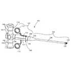
本実施形態における融合ケージ100および挿入器102の斜視図を示した図1を参照する。挿入器102は、その遠位端部に、融合ケージ100の近位端部181を実質的に相補的に取り付け可能とする融合ケージ接続部122を有する。近位側操作部114における挿入器102の近位端部には、押圧されると折り畳み自在コレット120(図1には図示せず)を挿入器遠位端部122から強制的に突出させる作動ボタン116が設けられている。 Reference is made to FIG. 1 showing a perspective view of the
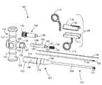
図2〜7に、近位側操作部、中間部および挿入部を有する挿入器の具体例を示す。 2 to 7 show specific examples of an inserter having a proximal operation portion, an intermediate portion, and an insertion portion.
図2に示すように、挿入器102は、第1グリップ101及び第2グリップ103を具備する近位側操作部114を有する。第1グリップ101及び第2グリップ103は、それぞれ挿入器102における長手軸と非平行に延在しており、第2グリップ103が第1グリップ101とは逆方向に延在している。これら第1グリップ101及び第2グリップ103には、近位側操作部114を握る際に役立つ操作溝164がそれぞれ形成されている。挿入器102の中間部107には、ロッキングスリーブ109によって包囲され得る近位側中空外軸108が設けられている。ロッキングスリーブ109は、第1ロッキングスリーブ部110と第2ロッキングスリーブ部111とからなる二つの半管状部を有する。第1ロッキングスリーブ部110から非平行に第1トリガ112が延在しており、第2ロッキングスリーブ部111から非平行に第2トリガ113が延在している。各ロッキングスリーブ部110,111は、開錠係合溝117(図2において図示せず)においても施錠係合溝118においてもスナップ係合するという特徴を有する。各係合溝117,118は、テーパ軸106の近位側に隣接する近位側中空外軸108の外面に配置されている。開錠係合溝117は、施錠係合溝118に僅かな距離隔てて近位側にて隣接する位置に設けられている。テーパ軸106は、挿入器102における中間部107の遠位端部に配置されている。このテーパ軸106は、挿入器102の挿入部105に向かうにつれて径が減少している。 As shown in FIG. 2, the
他の例(図示せず)において、近位側操作部は、挿入器の長手軸と非平行な一方向に延在する単一のグリップを有していてもよい。さらに、挿入器の長手軸と非平行な一方向に延在する長めのグリップと、この第1グリップと逆方向に延在する短めの第2グリップとを有していてもよい。 In another example (not shown), the proximal operating portion may have a single grip extending in one direction non-parallel to the longitudinal axis of the inserter. Further, it may have a long grip extending in one direction non-parallel to the longitudinal axis of the inserter and a short second grip extending in the opposite direction to the first grip.
他の例(図示せず)において、ロッキングスリーブは、挿入器の中間部を包囲する単一の管状部を有していてもよい。さらに、ロッキングスリーブは、第1トリガロッドを具備する単一のトリガ(図示せず)を有していてもよい。 In another example (not shown), the locking sleeve may have a single tubular portion that surrounds the middle portion of the inserter. Furthermore, the locking sleeve may have a single trigger (not shown) with a first trigger rod.
挿入部105は、中間部107におけるテーパ軸106の遠位端部から当該中間部107の長手軸と同方向に沿って延在する。この挿入部は、内腔を規定する外壁と融合ケージ100に接触する挿入器遠位端部122とを有する概して円形中空外軸104を有している。 The
折り畳み自在コレット120は、中空外軸104から独立して長手方向に移動する。この折り畳み自在コレット120は、開いた形態又は折り畳まれた形態を維持し得る。また折り畳み自在コレット120は、作動ボタン116が押圧された際に、挿入器遠位端部122における挿入部105の中空外軸104の内部から突出可能となっている。 The
図3を参照し、ロッキングスリーブ109が施錠位置に配置されて施錠係合溝118にスナップ係合した状態の挿入器102を示す。ロッキングスリーブ109を施錠位置に配置することで、ロッキングロッド136(図3には図示せず)が、コレット120の内部から強制的に突出されるだけでなく、挿入部105の内部から挿入器遠位端部122の外側に強制的に突出され、これによってコレット120の折り畳みがコントロール(controlling)される。 With reference to FIG. 3, the
図4を参照し、個々の部品を露出した分解図で挿入器102を示す。近位側操作部114は、操作グリップ101,103に対して非平行である長手方向に延在するハンドル内腔部162をさらに有する。作動アセンブリ138は、ハンドル内腔部162の少なくとも一部を通る。近位側操作部はまた、操作グリップ101,103に対して非平行な態様で遠位に延在する作動軸156を有する。作動軸156は、中間部107とのスライド自在な接続を可能とする操作部溝160と操作部リブ158とを有する。より具体的には、近位側中空外軸108が操作部溝160と係合し、中間部107の上部スロット接続部153が第1操作部リブ158と係合し、中間部107の下部スロット接続部155が第2操作部リブ159と係合する。各スロット接続部153,155は、近位側操作部114と中間部107との間に空洞を維持するようになっており、第1トリガロッド115が中間部107を通れるようになっている。近位側操作部114は、溶接により又はよく知られた他の方法により、中間部107と一旦係合されたら両者が互いに他方から切り離されないように、中間部としっかり固定されるのが好ましい。 Referring to FIG. 4, the
作動アセンブリ138は、作動体の内部にトグルアセンブリを有する。作動アセンブリ138の遠位端部には作動ボタン116が設けられている。作動アセンブリ138の近位端部には、プラグ140の遠位端部に隣接するダボ139が設けられている。
中間部107は、スロット接続部153を備えた近位側中空外軸108を有し、上記スロット接続部153は、施錠係合溝118の近位側の開錠係合溝117の近位側に設けられている。中間部の遠位端部は、挿入部105に向かうにつれて直径が減少するテーパ軸106となっている。プラグ140及びばね148は、実質的に挿入器102の長手軸と同じ軸に沿って近位側中空外軸108の少なくとも一部を通る形態となっている。プラグ140は、ばね148のばね近位端部152に隣接するプラグ遠位端部142を有する。プラグ遠位端部142は、干渉軸134の近位端部とも係止する。プラグはまた、細長のプラグ本体144を有し、プラグ本体144は、当該プラグ本体144の中央部を通る細長のプラグ開口部146を有する。細長のプラグ開口部146は、挿入器102又はプラグ140の長手軸に対して非平行な態様でプラグ本体144を通っている。プラグ内腔部147は、プラグ140の遠位端部から延設され、細長のプラグ開口部146と連通してプラグ140を通っている。 The
ばね148はまた、テーパ軸106の内表面に隣接するばね遠位端部150を有する。プラグ遠位端部142とテーパ軸106の内部とへの接触により、両表面の間でばね148が圧縮される。 The
ロッキングスリーブ109は、第1ロッキングスリーブ部110および第2ロッキングスリーブ部111により、中間部107の少なくとも一部を包囲する。第1ロッキングスリーブ部は、第1トリガ112の第1トリガロッド115を受け入れる第1ロッキングスリーブ開口部154を有する。第1トリガロッド115は、上部スロット接続部153へのアクセスを可能とする第1ロッキングスリーブ開口部154を通る。第1トリガロッド115は、細長のプラグ開口部146へのアクセスを可能とする上部スロット接続部153を通る。第1トリガロッド115は、下部スロット接続部155へのアクセスを可能とする細長のプラグ開口部146を通る。第1トリガロッド115は、第2トリガ113と第2ロッキングスリーブ部111との結合部において、第2ロッキングスリーブ部111と係合している下部スロット接続部153を通る。 The locking
干渉軸134は中空であり、干渉軸の内腔を規定する干渉軸壁を有する。この干渉軸134は、長手軸方向に沿って、少なくともその一部が中空外軸104の内側に配置される。干渉軸134の遠位端部には折り畳み自在コレット120が設けられている。ロッキングロッド136は、長手軸方向に沿って、少なくともその一部が干渉軸134の内側に配置される。干渉軸134の近位端部は、ばね148を長手方向に通るプラグ遠位端部142と係止している。ロッキングロッド136は、細長のプラグ開口部146を通って配置された第1トリガロッド115と係合するプラグ内腔部147を通っている。 The
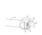
図5に示すように、挿入器遠位端部122は、挿入器溝129における向かい合った両側に挿入器遠位壁128を有し、挿入器溝129は、溝基部壁130と溝内長手方向壁132とを備えた、主として長方形の断面を備えた窪みを有する。挿入器溝129は、挿入器に対する融合ケージ100の取り付けを容易にする。中空外軸104の内側にはコレット120が備わっている。 As shown in FIG. 5, the inserter
図6に示すように、コレット120は、当該コレットの折り畳みを可能とするコレット溝121と、当該コレット120の中心から近位に移動するにつれて細くなるコレット近位端部166とを有する。このコレット120は、作動ボタン116が押圧されてダボ139が外側の位置に伸長され、プラグ140が遠位に押圧された際に、中空外軸104の内側から突出する。遠位に移動するプラグ140が干渉軸134を遠位に移動させることにより、コレット120が中空外軸104から突出する。 As shown in FIG. 6, the
図7に示すように、ロッキングロッドは、干渉軸134の内側から突出し得る。トリガ112,113を遠位に押圧することにより、ロッキングスリーブが開錠位置から施錠位置に向けて遠位に移動され、これによって、第1トリガロッドに連結されたロッキングロッド136が強制的に遠位に押しやられる。ロッキングロッド136は、コレット120の折り畳みをコントロールしている。 As shown in FIG. 7, the locking rod may protrude from the inside of the
挿入器102は、多数の部品から構成され、これらの部品が類似の又は多くの異なる材質から構成されることが好ましい。挿入器102及びそれらの部品は、如何なる金属、合金、準硬質プラスチック又はポリウレタンから構成されてもよい。干渉軸134及びコレット120は、挿入器102における残りの部品と同様の材質から構成されていてもよい。しかし、干渉軸140及びコレット120は、金属、合金等を含んでもよいが、エラストマー材料を含んではならない。また、部品は、直線状、曲線状、銃剣状、オフセット等のように、椎間腔に到達するために外科医が使用するアクセス用器具への適用を支援する図示した形態とは僅かに異なる形態も取り得る。このように、本発明の器具は、種々異なる外科的アプローチに適用し得る。 The
図8,図9は、空洞と、遠位壁と、側壁と、長方形の断面を有する頭部を含む近接部と、を有する融合ケージの具体例を示している。 8 and 9 show an example of a fusion cage having a cavity, a distal wall, a side wall, and a proximal portion including a head having a rectangular cross section.
図8に示すように、融合ケージ100は、連続面である遠位壁178と、概して長方形の断面を有し近位壁180から突出する頭部179を備えた挿入器接続部と、頭部179及び近位壁180の連結点で規定される肩部183と、近位壁180から遠位壁178にわたって互いがほぼ平行に延在する第1波形脊椎骨係合面188及び第2波形脊椎骨係合面189と、を具備する外壁を有している。第1側壁192及び第2側壁194は反対側に配置されるとともに、第1側壁192と平行に、各側壁192,194が近位壁180から遠位壁178にわたって長手方向に延在している。遠位壁178は、側壁192,194との連結点に丸みを帯びた端部又はテーパ状の端部を有していてもよい。融合ケージ開口部196は、融合ケージに沿って波形脊椎骨係合面188,189から長手方向に延在していてもよい。側壁192,194は、複数の微細孔172を有していてもよい。微細孔172は、同じ大きさであってもよいし異なる大きさであってもよい。また、融合ケージ100は、側壁192、近位壁180及び遠位壁178の中心に位置し、融合ケージ開口部196と連通する融合ケージ空洞186を有している。この融合ケージ空洞186には、融合ケージ開口部196又は微細孔172を介して骨形成物質が挿入されてもよい。 As shown in FIG. 8, the
図9に示すように、融合ケージの頭部179は、融合ケージ100の近位端から融合ケージ空洞186まで長手方向に延在する概して円形の逆テーパ開口部170を有していてもよい。逆テーパ開口部170は、実質的に斜め方向又は遠位短手方向に延在するコレット係合面168を有している。逆テーパ開口部170は、挿入器102に対する融合ケージ100の取り付けを促進する当該挿入器102のコレット120を受け入れ得る。この逆テーパ開口部は、コレットを介してケージを挿入器に保持するという同様の機能を達成するために、種々の幾何学的な態様や係合機構(円錐形のテーパ又は段部を有する穴等)を取り得る。融合ケージ頭部179は、挿入器溝129に滑り込んで一時的に(complimentary)係合し得る。融合ケージ基底面184が挿入器溝の溝基部壁130と係合するだけでなく、融合ケージ頭部側壁182が、挿入器における挿入器溝内の溝内長手方向壁132と係合する。 As shown in FIG. 9, the
融合ケージ100には、位置決め穴174,176が設けられており、融合ケージ100が二つの脊椎骨の間の正しい位置に配置されたか否かを判断するために用いられ得る。近位の位置決め穴174は、第1波形脊椎骨係合面188に空けられ、側壁192と融合ケージ空洞186との間における融合ケージ100の近位端部に向けて設けられている。遠位の位置決め穴176は、第2波形脊椎骨係合面189に空けられ、反対側の側壁194と融合ケージ空洞186との間における融合ケージ100の遠位端部に向けて設けられている。椎間腔内のX線撮影において融合ケージ100の正確な配置を容易に検出できるように、各位置決め穴内にタンタル線マーカーが挿入される。しかしながら、二つの脊椎骨間における融合ケージ100の適切な配置を容易にするためには、位置決め穴174,176内に挿入する部材として如何なる放射線不透過材料や形態を用いてもよい。 The
融合ケージ100は、炭素繊維強化PEEK(ポリエーテルエーテルケトン樹脂)で構成されることが好ましい。しかしながら、特に限定しないが、例えば、ステンレス鋼、チタン及びその合金、コバルトクロム及びその合金、セラミック、高分子材料、生分解性材料および骨同種移植片材料、などを含む如何なる生体適合性材料が用いられてもよい。 The
図10に、変形例の融合ケージ200を示す。大部分の特徴は前述の融合ケージ100と変わらず同様であるが、融合ケージ200は、複数の微細孔を保ちつつ、より少数の微細孔172を有していてもよく、遠位端178は、側壁192,194に向けてより急勾配になるように細くなっていてもよい。さらに、波形脊椎骨係合面188,189は、より多くの又はより少数の突起部を有していてもよい。 FIG. 10 shows a modified fusion cage 200. Most of the features are the same as the
融合ケージが取り得る他の変形例として、各側壁192,194が単一の微細孔(図示せず)を有していてもよい。さらにまた、融合ケージ遠位壁178に開口部、微細孔その他の穴(図示せず)を設けることとしてもよい。 As another variation that the fusion cage can take, each
図11〜14に、融合ケージを挿入器に取付けたり挿入器から融合ケージを取り外したりするための本発明の実施方法を示す。図11に示すように、融合ケージ100は、挿入器遠位端部122において挿入器102と係合している。融合ケージの頭部179は、挿入器溝129内にスライド自在に配置されている。ユーザが作動ボタン116を押圧することにより、トグルアセンブリがダボ139を遠位に押しながら強制的に外側の位置に移動され、これによってプラグとテーパ軸106の内部との間においてばね148を圧縮しながらプラグ140が強制的に遠位に移動され、その結果、干渉軸134が遠位に移動されてコレット120が挿入器遠位端部122から突出されることとなり、コレット120が強制的に遠位に移動される。より具体的には、コレット120が挿入器溝129の内側から突出される。コレット120は、逆テーパ開口部170に規制されるにつれて強制的に折り畳まれた状態となり、融合ケージ120の逆テーパ開口部170内に挿入されるにつれて小径となる。コレット120は、融合ケージ空洞186の少なくとも一部に入った状態となってもよい。コレット120は、逆テーパ開口部170を通った後、開いた状態又は元の径に戻る。 FIGS. 11-14 illustrate the practice of the present invention for attaching and removing the fusion cage to and from the inserter. As shown in FIG. 11, the
図12に示すように、ユーザがトリガ112,113を遠位に向けて強く押すことにより、ロッキングロッド130が干渉軸134の内側から遠位に突出され、ロッキングスリーブが強制的に開錠位置から施錠位置に移動される(図3参照)。トリガ112,113を強制的に遠位に押すことにより、ロッキングスリーブ109と開錠係合溝117との係合が強制的に外され、ロッキングスリーブ109が施錠係合溝118に係合する。第1トリガロッド115は、ロッキングロッド136を強制的に遠位に移動させ、干渉軸134から、より具体的にはコレット120から、突出させる。ロッキングロッド136は、コレット120の折り畳みをコントロールする。 As shown in FIG. 12, when the user strongly pushes the
図13に示すように、ユーザが作動ボタン116を押圧することにより、ダボ139を近位に引きながらトグルアセンブリが強制的に内側の位置に移動され、プラグ140を強制的に遠位に移動させながらばね148が強制的に伸ばされる。コレット120は引かれて逆テーパ開口部170と係合する。ロッキングロッドは、コレットの折り畳みをコントロールし、これによってコレット近位端部166が融合ケージ100における逆テーパ開口部170のコレット係合面168と係合する。コレットを引くことにより、融合ケージ頭部179が挿入器溝129に完全に係合する。挿入器遠位壁128は融合ケージ近位壁180に係合する。溝基部壁130は融合ケージ基底面184に係合し、溝内長手方向壁132は融合ケージ頭部側壁182に係合する。融合ケージ100は、コレット120が融合ケージ100の逆テーパ開口部170に係合した後においては、挿入器102から独立して操作できないようになっている。 As shown in FIG. 13, when the user presses the
融合ケージ100は、挿入器102を操作するユーザによって椎間腔内に配置される。脊椎骨係合面188,189は、上側及び下側の脊椎骨と係合し得る。融合ケージ空洞186内には、骨形成物質が挿入されてもよい。 The
図14に示すように、融合ケージ100の解放は、コレット120からロッキングロッド136を引くことで達成される。ユーザがトリガ112,113を引いて施錠位置から開錠位置に後退させることで、施錠係合溝118とロッキングスリーブ109との係合が外れ、ロッキングスリーブ109が近位に移動して開錠係合溝117内に係合する。ロッキングロッド136を引くことにより、融合ケージ100からコレット120が外れ、より具体的には、逆テーパ開口部170を通ってコレット120が折り畳まれる。ばね148は、元の長さに拡張してテーパ軸106の内部及びプラグ140を押圧する。プラグが強制的に近位に移動されると、干渉軸134が引かれる。コレット120は、逆テーパ開口部170を通って折り畳まれ、中空外軸104内に引かれる。融合ケージ100は、ユーザが外科患者から挿入器102を引き抜いても、摩擦力によって二つの脊椎骨間に配置されたままとなる。 As shown in FIG. 14, the release of the
本発明は、その主旨又は本質的な特徴を逸脱しない範囲で、他の態様に具現化してもよい。例えば、上記の記述は、背骨手術用の挿入器及び融合ケージの選択可能な実施形態として記載した。上記各実施形態で記載した様々な特徴を組み合わせて他の多様な組み合わせ及び代替手段を形成することが好ましい。また、このシステムは単一の使用方法に限定されないことが好ましい。この挿入器及び融合ケージの取り付けシステムは、融合ケージの配置又は置換を必要とするどのような背骨手術に用いられてもよい。このように、上記の実施形態は、あらゆる点で単に説明的と解釈されるべきであり、限定的に解釈されるべきでない。したがって、本発明の範囲は、上述した記載よりもむしろ添付した特許請求の範囲によって示される。特許請求の範囲の均等物の範囲内において生じる全ての変形は、これらの範囲内に含まれると解されるべきである。 The present invention may be embodied in other forms without departing from the spirit or essential characteristics thereof. For example, the above description has been presented as an alternative embodiment of an inserter and fusion cage for spinal surgery. It is preferable to combine various features described in the above embodiments to form various other combinations and alternative means. Also, the system is preferably not limited to a single method of use. This inserter and fusion cage attachment system may be used in any spinal surgery that requires placement or replacement of the fusion cage. Thus, the above embodiments should be construed as merely illustrative in all respects and not as restrictive. The scope of the invention is, therefore, indicated by the appended claims rather than by the foregoing description. All changes that come within the scope of the equivalents of the claims should be construed as being included within these scope.
Claims (37)
Translated fromJapanese前記融合ケージは外壁を有し、
前記外壁は、遠位端部と近位端部とを有し、
前記近位端部は、近位壁と、前記融合ケージに対する挿入器の取り付けを容易化する態様に形成された挿入器接続部と、を有し、
前記挿入器接続部は、長方形断面を有する頭部を有し、前記頭部が前記近位壁から突出して近位壁との連結部において肩部を規定しているシステム。A system having a fusion cage sized to be inserted between a first vertebra and a second vertebra,
The fusion cage has an outer wall;
The outer wall has a distal end and a proximal end;
The proximal end has a proximal wall and an inserter connection formed in a manner that facilitates attachment of the inserter to the fusion cage;
The inserter connection has a head having a rectangular cross-section, the head protruding from the proximal wall and defining a shoulder at a joint with the proximal wall.
前記長方形断面は正方形断面を含む。The system of claim 1, wherein
The rectangular cross section includes a square cross section.
前記頭部は、前記挿入器のコレットをスライド自在に受け入れる大きさの逆テーパ開口部を有する。The system of claim 1, wherein
The head has a reverse taper opening sized to slidably receive the collet of the inserter.
前記外壁は、前記第1脊椎骨とスライド不可に係合する第1波形脊椎骨係合面と、前記第2脊椎骨とスライド不可に係合する第2波形脊椎骨係合面と、をさらに有する。The system of claim 1, wherein
The outer wall further includes a first corrugated vertebra engaging surface that non-slidably engages with the first vertebra, and a second corrugated vertebra engaging surface that non-slidably engages with the second vertebra.
前記外壁は、前記第1波形脊椎骨係合面が前記第1脊椎骨に隣接して配置されるとともに、前記第2波形脊椎骨係合面が前記第2脊椎骨に隣接して配置された際に、前記融合ケージ内の中心部に配された空洞への骨形成物質の挿入または前記空洞内への骨増殖を許容する大きさの第1開口部を備えた第1側壁をさらに有する。The system of claim 4, wherein
The outer wall has the first corrugated vertebra engaging surface disposed adjacent to the first vertebra and the second corrugated vertebra engaging surface disposed adjacent to the second vertebra. It further has a first sidewall with a first opening sized to allow insertion of bone forming material into a cavity located in the central portion of the fusion cage or bone growth into the cavity.
前記外壁は、前記第1波形脊椎骨係合面が前記第1脊椎骨に隣接して配置され、前記第2波形脊椎骨係合面が前記第2脊椎骨に隣接して配置された際に、前記空洞への骨形成物質の挿入または前記空洞内への骨増殖を許容する大きさの第2開口部を備えた第2側面をさらに有する。The system of claim 5, wherein
The outer wall has a first corrugated vertebra engaging surface disposed adjacent to the first vertebra, and a second corrugated vertebra engaging surface disposed adjacent to the second vertebra. And a second side with a second opening sized to allow insertion of a bone forming substance or bone growth into the cavity.
前記頭部は開口部を有し、
前記システムは、前記挿入器をさらに有し
前記挿入器は、前記頭部を受け入れ可能な長方形断面を有する凹部と、前記頭部の開口部に挿入可能な折り畳み自在コレットと、をさらに有する。The system of claim 1, wherein
The head has an opening;
The system further comprises the inserter, wherein the inserter further comprises a recess having a rectangular cross section capable of receiving the head and a collapsible collet insertable into the opening of the head.
前記融合ケージ挿入器は、近位側操作部と挿入部とを有し、
前記挿入部は、
内腔を規定する外壁を備えた中空外軸と、
少なくとも一部が前記内腔内に配置された中空干渉軸であって、干渉軸内腔を規定する干渉軸壁と前記干渉軸の遠位端部に配置された折り畳み自在コレットとを備えた中空干渉軸と、
少なくとも一部が前記干渉軸内腔内に配置されるとともに、少なくとも一部が前記干渉軸内腔から突出して前記コレットの折り畳みをコントロールするように配置可能とされたロッキングロッドと、を有するシステム。A system having a fusion cage inserter comprising:
The fusion cage inserter has a proximal operation portion and an insertion portion,
The insertion part is
A hollow outer shaft with an outer wall defining a lumen;
A hollow interference shaft at least partially disposed within the lumen, the hollow interference shaft including an interference shaft wall defining the interference shaft lumen and a collapsible collet disposed at a distal end portion of the interference shaft An interference axis;
A locking rod disposed at least partially within the interference shaft lumen and at least partially projecting from the interference shaft lumen and configured to control folding of the collet.
前記外壁は、前記挿入器に対する前記融合ケージの取り付けを容易化する融合ケージ接続部を有し、
前記融合ケージ接続部は、前記外壁の遠位端部に前記融合ケージにおける長方形の頭部をスライド自在に受け入れ得る長方形断面の凹部を有する。The system of claim 8, wherein
The outer wall has a fusion cage connection that facilitates attachment of the fusion cage to the inserter;
The fusion cage connection has a rectangular cross-sectional recess at the distal end of the outer wall that can slidably receive a rectangular head of the fusion cage.
前記コレットは、当該コレットが前記融合ケージ内における逆テーパ開口部と係合するように、その遠位端部が近位端部よりも拡開するように傾斜している。The system of claim 8, wherein
The collet is angled such that its distal end is wider than the proximal end so that the collet engages a reverse taper opening in the fusion cage.
前記挿入部は、
当該挿入部の近位端部内に配され、前記中空干渉軸の近位端部と係合する細長のプラグ開口部と、前記ロッキングロッドをスライド自在に受け入れる遠位端部プラグ開口部と、を備えたプラグと、
前記プラグの遠位端部に隣接するばねと、をさらに有する。The system of claim 8, wherein
The insertion part is
An elongate plug opening disposed within the proximal end of the insert and engaging the proximal end of the hollow interference shaft; and a distal end plug opening slidably receiving the locking rod. A plug with
And a spring adjacent to the distal end of the plug.
前記操作部には作動アセンブリが収納され、
前記作動アセンブリは、内側位置と外側位置との間において切り替え可能なトグルアセンブリと、作動ボタンと、前記作動アセンブリから突出して前記プラグの遠位端部と係合するダボと、を有し、
前記トグルアセンブリが前記内側位置に配置されることで前記折り畳み自在コレットが前記中空外軸から強制的に突出され、前記トグルアセンブリが前記外側位置に配置されることで前記折り畳み自在コレットが前記中空外軸内に引かれる。The system of claim 11, wherein
An operating assembly is housed in the operating portion,
The actuating assembly includes a toggle assembly switchable between an inner position and an outer position, an actuating button, and a dowel protruding from the actuating assembly and engaging the distal end of the plug;
The collapsible collet is forcibly protruded from the hollow outer shaft when the toggle assembly is disposed at the inner position, and the collapsible collet is disposed at the outer position when the toggle assembly is disposed at the outer position. Pulled into the shaft.
前記作動ボタンは、当該作動ボタンを押圧することによって前記トグルアセンブリが前記外側位置に移動され、前記ダボが強制的に前記作動アセンブリからさらに突出され、前記プラグと前記ばねとが遠位に押圧され、これによって前記コレットが前記外軸から強制的に突出されるように前記トグルアセンブリの遠位端部に隣接する。The system of claim 12, wherein
The actuating button pushes the actuating button to move the toggle assembly to the outer position, forcing the dowel further out of the actuating assembly, and pushing the plug and the spring distally. , Thereby adjoining the distal end of the toggle assembly such that the collet is forced out of the outer shaft.
前記融合ケージ挿入器は、近位側操作部と、挿入部と、ロッキングスリーブと、を有し、
前記挿入部は、折り畳み自在コレットと、干渉軸と、少なくとも一部が前記干渉軸内に配置されたロッキングロッドと、を有し、
前記ロッキングスリーブは、少なくとも一部において前記挿入部の近接部を包囲するとともに、前記近位側操作部に対してスライド自在であることにより、前記コレットに対して前記ロッキングロッドを移動させて前記コレットの連結をコントロールするシステム。A system having a fusion cage inserter comprising:
The fusion cage inserter includes a proximal operation portion, an insertion portion, and a locking sleeve,
The insertion portion has a collapsible collet, an interference shaft, and a locking rod at least partially disposed within the interference shaft,
The locking sleeve at least partially surrounds the proximity portion of the insertion portion and is slidable with respect to the proximal operation portion, thereby moving the locking rod with respect to the collet. A system that controls the connection of
前記ロッキングスリーブは、ロッキングスリーブ開口部を有する半管状の第1ロッキングスリーブ部材と、第1トリガロッドを有する第1トリガと、を有し、
前記第1トリガロッドは、前記ロッキングスリーブ開口部、前記挿入部および細長のプラグ開口部を通る。The system of claim 14, wherein
The locking sleeve includes a semi-tubular first locking sleeve member having a locking sleeve opening, and a first trigger having a first trigger rod;
The first trigger rod passes through the locking sleeve opening, the insert and an elongated plug opening.
前記ロッキングスリーブは、前記第1トリガロッドと係合する半管状の第2ロッキングスリーブ部材と、前記ロッキングスリーブにおいて前記第1トリガの反対側に配置された第2トリガと、をさらに有する。The system of claim 15, wherein
The locking sleeve further includes a semi-tubular second locking sleeve member that engages with the first trigger rod, and a second trigger disposed on the locking sleeve opposite the first trigger.
前記第1トリガロッドは、前記ロッキングロッドの前記近位端部と係合する。The system of claim 15, wherein
The first trigger rod engages the proximal end of the locking rod.
前記ロッキングスリーブは、半管状の第2ロッキングスリーブ部材をさらに有し、前記トリガロッドは、前記挿入部および前記細長のプラグ開口部を通って前記第2ロッキングスリーブ部材の内面に取り付けられる。The system of claim 15, wherein
The locking sleeve further includes a semi-tubular second locking sleeve member, and the trigger rod is attached to the inner surface of the second locking sleeve member through the insertion portion and the elongated plug opening.
前記ロッキングスリーブの遠位端部には、前記挿入部と係合するスナップ機構が設けられている。The system of claim 14, wherein
A snap mechanism that engages with the insertion portion is provided at the distal end portion of the locking sleeve.
前記スナップ機構は、前記ロッキングロッドが前記コレット内に延出して前記融合ケージの開口部から前記コレットが引かれることをコントロールする施錠位置と、前記施錠位置から離れ、前記ロッキングロッドが前記コレット内から離れて前記開口部から前記コレットが引かれることを許容する開錠位置と、において前記ロッキングスリーブに嵌合する。The system of claim 19, wherein
The snap mechanism includes a locking position that controls the locking rod extending into the collet and pulling the collet from the opening of the fusion cage, and the locking mechanism is separated from the locking position, and the locking rod is moved from the collet. The locking sleeve is fitted in an unlocked position that allows the collet to be pulled away from the opening.
挿入器の近傍に融合ケージを配置する配置工程;
前記挿入器に前記融合ケージを連結する連結工程:前記融合ケージは、遠位端部と近位端部とを具備する外壁を有し、前記近位端部は近位壁と挿入器接続部とを有し、前記挿入器接続部は長方形断面の頭部を有し、前記頭部は前記近位壁から突出して近位壁との連結点における肩部を規定する;
前記挿入器を用いて第1脊椎骨と第2脊椎骨との間の椎間腔内に前記融合ケージを挿入する挿入工程;
前記連結工程は、前記挿入器の遠位端部に形成された長方形断面を有する凹部内に前記頭部を挿入する工程を含む。A method having the following steps.
A placement step of placing the fusion cage in the vicinity of the inserter;
Connecting the fusion cage to the inserter: The fusion cage has an outer wall having a distal end and a proximal end, the proximal end being a proximal wall and an inserter connection. And the inserter connection has a rectangular cross-section head that protrudes from the proximal wall and defines a shoulder at a point of connection with the proximal wall;
An insertion step of inserting the fusion cage into the intervertebral space between the first vertebra and the second vertebra using the inserter;
The connecting step includes the step of inserting the head into a recess having a rectangular cross section formed at the distal end of the inserter.
前記各長方形断面は正方形断面を含む。The method of claim 21, wherein
Each rectangular cross section includes a square cross section.
前記頭部は逆テーパ開口部を有し、
前記連結工程は、さらに前記挿入器の折り畳み自在コレットを前記逆テーパ開口部に挿入する工程を含む。The method of claim 21, wherein
The head has a reverse tapered opening;
The connecting step further includes a step of inserting the collapsible collet of the inserter into the reverse tapered opening.
前記外壁は、第1波形椎間骨係合面と第2波形椎間骨係合面とを有し、
前記挿入工程は、前記第1脊椎骨及び前記第1波形椎間骨係合面をスライド不可に係合させる工程と、前記第2脊椎骨及び前記第2波形椎間骨係合面をスライド不可に係合させる工程と、を含む。The method of claim 21, wherein
The outer wall has a first corrugated intervertebral bone engaging surface and a second corrugated intervertebral bone engaging surface;
The inserting step includes a step of non-slidably engaging the first vertebra and the first corrugated intervertebral engaging surface, and a non-slidable engagement of the second vertebra and the second corrugated intervertebral engaging surface. Combining.
前記外壁は、第1開口部を備えた第1側壁をさらに有し、
前記第1波形椎間骨係合面が前記第1脊椎骨とスライド不可に係合されるとともに前記第2波形椎間骨係合面が前記第2脊椎骨とスライド不可に係合された後に、前記第1開口部を介して前記融合ケージ内の中心部に骨形成物質を挿入する工程をさらに有する。25. The method of claim 24, wherein
The outer wall further has a first side wall with a first opening,
After the first corrugated intervertebral engagement surface is slidably engaged with the first vertebra and the second corrugated intervertebral engagement surface is nonslidably engaged with the second vertebra; The method further includes the step of inserting an osteogenic material into the central portion of the fusion cage through the first opening.
挿入器の近傍に融合ケージを配置する配置工程:前記融合ケージは開口部を有し、前記挿入器は近位側操作部と挿入部とを有し、前記挿入部は、中空外軸、中空干渉軸及びロッキングロッドを有する;
前記融合ケージを前記挿入器に連結する連結工程;
前記挿入器を用いて第1脊椎骨と第2脊椎骨との間の椎間腔内に前記融合ケージを挿入する挿入工程;
前記中空外軸は、その内腔を規定する外壁を有し、
前記中空干渉軸は、少なくともその一部が前記中空外軸の内腔内に配置されるとともに、干渉軸内腔を規定する干渉軸壁と前記干渉軸の遠位端部に配置された折り畳み自在コレットとを有し、
前記連結工程は、
前記折り畳み自在コレットを前記開口部に挿入する工程と、
前記ロッキングロッドを前記折り畳み自在コレット内に移動させて前記折り畳み自在コレットの折り畳みを防止し、これによって前記折り畳み自在コレットが前記開口部から引き抜かれることを防止する工程と、を有する。A method having the following steps.
Arrangement step of arranging the fusion cage in the vicinity of the inserter: the fusion cage has an opening, the inserter has a proximal operation part and an insertion part, and the insertion part has a hollow outer shaft, a hollow Having an interference shaft and a locking rod;
A connecting step of connecting the fusion cage to the inserter;
An insertion step of inserting the fusion cage into the intervertebral space between the first vertebra and the second vertebra using the inserter;
The hollow outer shaft has an outer wall defining its lumen;
The hollow interference shaft is at least partially disposed in the lumen of the hollow outer shaft, and is foldable so as to be disposed at the interference shaft wall defining the interference shaft lumen and the distal end of the interference shaft. Having a collet,
The connecting step includes
Inserting the foldable collet into the opening;
Moving the locking rod into the collapsible collet to prevent folding of the collapsible collet, thereby preventing the collapsible collet from being pulled out of the opening.
前記外壁は、当該外壁の遠位端部に形成された凹部を具備する融合ケージ接続部を有し、
前記凹部は長方形断面を有し、
前記融合ケージは、長方形断面を有する長方形の頭部を有し、
前記連結工程は、前記凹部内に前記頭部を受け入れる工程をさらに有する。27. The method of claim 26.
The outer wall has a fusion cage connection comprising a recess formed at a distal end of the outer wall;
The recess has a rectangular cross section;
The fusion cage has a rectangular head with a rectangular cross section;
The connecting step further includes a step of receiving the head in the recess.
前記コレットは、当該コレットの遠位端部が近位端部よりも拡開するように傾斜し、
前記開口部は逆テーパ開口部を有する。27. The method of claim 26.
The collet is inclined such that the distal end of the collet is wider than the proximal end;
The opening has a reverse tapered opening.
前記挿入部は、さらに当該挿入部の近位端部内にプラグを有し、
前記プラグは、前記中空干渉軸の近位端部と係合する細長のプラグ開口部と、前記ロッキングロッドをスライド自在に受け入れる遠位端部プラグ開口部と、を有し、
前記折り畳み自在コレットが前記内腔から延出するように、前記プラグをスライドさせて前記中空干渉軸を移動させる移動工程と、
前記プラグに隣接するばねを、前記プラグのスライドに応じて歪める工程と、をさらに有する。27. The method of claim 26.
The insert further comprises a plug in the proximal end of the insert;
The plug has an elongated plug opening that engages a proximal end of the hollow interference shaft, and a distal end plug opening that slidably receives the locking rod;
A moving step of moving the hollow interference shaft by sliding the plug so that the collapsible collet extends from the lumen;
And a step of distorting a spring adjacent to the plug in response to sliding of the plug.
前記操作部には、トグルアセンブリを有する作動アセンブリが収納され、
前記トグルアセンブリは、作動ボタンと、前記トグルアセンブリの遠位端部から突出するダボとを有し、
前記移動工程は、前記トグルアセンブリを外側位置から内側位置に切り替えるように作動ボタンを押圧する工程を有し、前記内側位置では、前記プラグがより遠くにスライドされるように前記ダボがさらに突出される。30. The method of claim 29, wherein
The operating portion houses an actuation assembly having a toggle assembly,
The toggle assembly has an activation button and a dowel protruding from the distal end of the toggle assembly;
The moving step includes a step of pressing an operation button to switch the toggle assembly from an outer position to an inner position, and the dowel is further protruded at the inner position so that the plug is slid further. The
挿入器の近傍に融合ケージを配置する配置工程:前記融合ケージは開口部を有し、前記挿入器は近位側操作部とロッキングスリーブと挿入部とを有し、前記挿入部は折り畳み自在コレットと中空干渉軸とロッキングロッドとを有する;
前記融合ケージを前記挿入器に連結する連結工程;
前記挿入器を用いて第1脊椎骨と第2脊椎骨との間の椎間腔内に前記融合ケージを挿入する挿入工程;
前記ロッキングスリーブは、少なくとも前記挿入部における近位端部の一部を包囲し、
前記連結工程は、前記折り畳み自在コレットを前記開口部に挿入する工程と、前記コレットに対して前記ロッキングロッドを移動させることにより、前記近位側操作部に対して前記ロッキングスリーブをスライドさせて前記コレットを前記融合ケージに連結する工程と、を有する。A method having the following steps.
Arrangement step of arranging the fusion cage in the vicinity of the inserter: the fusion cage has an opening, the inserter has a proximal operation portion, a locking sleeve, and an insert portion, and the insert portion is a collapsible collet And a hollow interference shaft and a locking rod;
A connecting step of connecting the fusion cage to the inserter;
An insertion step of inserting the fusion cage into the intervertebral space between the first vertebra and the second vertebra using the inserter;
The locking sleeve surrounds at least a portion of the proximal end of the insert;
The connecting step includes inserting the foldable collet into the opening, and moving the locking rod with respect to the collet, thereby sliding the locking sleeve with respect to the proximal side operation unit. Connecting a collet to the fusion cage.
前記ロッキングスリーブは、ロッキングスリーブ開口部を有する半管状の第1ロッキングスリーブ部材と、第1トリガロッドを有する第1トリガと、を有し、
前記第1トリガロッドは、前記ロッキングスリーブ開口部、前記挿入部および細長のプラグ開口部を通る。32. The method of claim 31, wherein
The locking sleeve includes a semi-tubular first locking sleeve member having a locking sleeve opening, and a first trigger having a first trigger rod;
The first trigger rod passes through the locking sleeve opening, the insert and an elongated plug opening.
前記ロッキングスリーブは、前記第1トリガロッドと係合する半管状の第2ロッキングスリーブ部材と、前記ロッキングスリーブにおいて前記第1トリガの反対側に配置された第2トリガと、をさらに有する。The method of claim 32, wherein
The locking sleeve further includes a semi-tubular second locking sleeve member that engages with the first trigger rod, and a second trigger disposed on the locking sleeve opposite the first trigger.
前記第1トリガロッドは、前記ロッキングロッドの前記近位端部と係合する。The method of claim 32, wherein
The first trigger rod engages the proximal end of the locking rod.
前記ロッキングスリーブは、さらに半管状の第2ロッキングスリーブ部材を有し、前記トリガロッドは、前記挿入部および前記細長のプラグ開口部を通って前記第2ロッキングスリーブ部材の内面に取り付けられる。The method of claim 32, wherein
The locking sleeve further includes a semi-tubular second locking sleeve member, and the trigger rod is attached to the inner surface of the second locking sleeve member through the insertion portion and the elongated plug opening.
前記ロッキングスリーブの遠位端部には、前記挿入部に嵌合するスナップ機構が設けられている。32. The method of claim 31, wherein
At the distal end of the locking sleeve, a snap mechanism that fits into the insertion portion is provided.
前記スナップ機構は、前記ロッキングロッドが前記コレット内に延出して前記融合ケージの開口部から前記コレットが引かれることをコントロールする施錠位置と、前記施錠位置から離れ、前記ロッキングロッドが前記コレット内から離れて前記開口部から前記コレットが引かれることを許容する開錠位置と、において前記ロッキングスリーブに嵌合する。The method of claim 36, wherein
The snap mechanism includes a locking position that controls the locking rod extending into the collet and pulling the collet from the opening of the fusion cage, and the locking mechanism is separated from the locking position, and the locking rod is moved from the collet. The locking sleeve is fitted in an unlocked position that allows the collet to be pulled away from the opening.
Applications Claiming Priority (1)
| Application Number | Priority Date | Filing Date | Title |
|---|---|---|---|
| US12/262,824US20100114105A1 (en) | 2008-10-31 | 2008-10-31 | System and method for vertebral interbody fusion |
Publications (1)
| Publication Number | Publication Date |
|---|---|
| JP2010104764Atrue JP2010104764A (en) | 2010-05-13 |
Family
ID=42132332
Family Applications (1)
| Application Number | Title | Priority Date | Filing Date |
|---|---|---|---|
| JP2009084504APendingJP2010104764A (en) | 2008-10-31 | 2009-03-31 | System and method for vertebral interbody fusion |
Country Status (2)
| Country | Link |
|---|---|
| US (1) | US20100114105A1 (en) |
| JP (1) | JP2010104764A (en) |
Cited By (3)
| Publication number | Priority date | Publication date | Assignee | Title |
|---|---|---|---|---|
| JP2018075397A (en)* | 2014-06-04 | 2018-05-17 | ヴェンツェル スパイン,インコーポレイテッド | Interbody fusion device that expands bilaterally |
| JP2019051312A (en)* | 2017-09-14 | 2019-04-04 | デピュイ・アイルランド・アンリミテッド・カンパニーDepuy Ireland Unlimited Company | Orthopedic instrument system and method for removing a trial structure assembly |
| US11219531B2 (en) | 2019-04-10 | 2022-01-11 | Wenzel Spine, Inc. | Rotatable intervertebral spacing implant |
Families Citing this family (56)
| Publication number | Priority date | Publication date | Assignee | Title |
|---|---|---|---|---|
| US6793678B2 (en) | 2002-06-27 | 2004-09-21 | Depuy Acromed, Inc. | Prosthetic intervertebral motion disc having dampening |
| WO2008070863A2 (en) | 2006-12-07 | 2008-06-12 | Interventional Spine, Inc. | Intervertebral implant |
| US20080161929A1 (en) | 2006-12-29 | 2008-07-03 | Mccormack Bruce | Cervical distraction device |
| US8900307B2 (en) | 2007-06-26 | 2014-12-02 | DePuy Synthes Products, LLC | Highly lordosed fusion cage |
| US8142441B2 (en)* | 2008-10-16 | 2012-03-27 | Aesculap Implant Systems, Llc | Surgical instrument and method of use for inserting an implant between two bones |
| US8591587B2 (en) | 2007-10-30 | 2013-11-26 | Aesculap Implant Systems, Llc | Vertebral body replacement device and method for use to maintain a space between two vertebral bodies within a spine |
| EP2237748B1 (en) | 2008-01-17 | 2012-09-05 | Synthes GmbH | An expandable intervertebral implant |
| US8216317B2 (en) | 2008-03-31 | 2012-07-10 | Stryker Spine | Spinal implant apparatus and methods |
| US8936641B2 (en) | 2008-04-05 | 2015-01-20 | DePuy Synthes Products, LLC | Expandable intervertebral implant |
| US8361152B2 (en) | 2008-06-06 | 2013-01-29 | Providence Medical Technology, Inc. | Facet joint implants and delivery tools |
| US9381049B2 (en) | 2008-06-06 | 2016-07-05 | Providence Medical Technology, Inc. | Composite spinal facet implant with textured surfaces |
| US11224521B2 (en) | 2008-06-06 | 2022-01-18 | Providence Medical Technology, Inc. | Cervical distraction/implant delivery device |
| US9333086B2 (en) | 2008-06-06 | 2016-05-10 | Providence Medical Technology, Inc. | Spinal facet cage implant |
| US9526620B2 (en) | 2009-03-30 | 2016-12-27 | DePuy Synthes Products, Inc. | Zero profile spinal fusion cage |
| WO2011080404A1 (en)* | 2009-12-28 | 2011-07-07 | Sterispine Sas | Device for positioning an implant |
| EP2547292B1 (en) | 2010-03-16 | 2019-04-24 | Pinnacle Spine Group, LLC | Ntervertebral implants and graft delivery systems |
| US9907560B2 (en) | 2010-06-24 | 2018-03-06 | DePuy Synthes Products, Inc. | Flexible vertebral body shavers |
| US8979860B2 (en) | 2010-06-24 | 2015-03-17 | DePuy Synthes Products. LLC | Enhanced cage insertion device |
| US8858637B2 (en) | 2010-09-30 | 2014-10-14 | Stryker Spine | Surgical implant with guiding rail |
| US9402732B2 (en) | 2010-10-11 | 2016-08-02 | DePuy Synthes Products, Inc. | Expandable interspinous process spacer implant |
| EP2535021B1 (en)* | 2011-06-14 | 2015-10-14 | Biedermann Technologies GmbH & Co. KG | Intervertebral implant |
| ES2555065T3 (en) | 2011-06-14 | 2015-12-28 | Biedermann Technologies Gmbh & Co. Kg | Device for inserting an intervertebral implant into a body and system comprising an intervertebral implant and a device for inserting it |
| AU2012332447A1 (en)* | 2011-11-01 | 2014-05-15 | Amedica Corporation | Implants with a connectable insert and related systems and methods |
| US9380932B1 (en) | 2011-11-02 | 2016-07-05 | Pinnacle Spine Group, Llc | Retractor devices for minimally invasive access to the spine |
| EP2838452B1 (en)* | 2012-04-16 | 2019-05-08 | BioSpine, LLC | Multiple spindle adjustable interbody fusion devices |
| USD732667S1 (en) | 2012-10-23 | 2015-06-23 | Providence Medical Technology, Inc. | Cage spinal implant |
| USD745156S1 (en) | 2012-10-23 | 2015-12-08 | Providence Medical Technology, Inc. | Spinal implant |
| EP2928418A4 (en) | 2012-12-07 | 2016-12-21 | Providence Medical Tech Inc | Apparatus and method for bone screw deployment |
| US9119948B2 (en) | 2013-02-20 | 2015-09-01 | Covidien Lp | Occlusive implants for hollow anatomical structures, delivery systems, and related methods |
| US9717601B2 (en) | 2013-02-28 | 2017-08-01 | DePuy Synthes Products, Inc. | Expandable intervertebral implant, system, kit and method |
| US9522070B2 (en) | 2013-03-07 | 2016-12-20 | Interventional Spine, Inc. | Intervertebral implant |
| WO2014159739A1 (en) | 2013-03-14 | 2014-10-02 | Pinnacle Spine Group, Llc | Interbody implants and graft delivery systems |
| JP2016538086A (en)* | 2013-11-26 | 2016-12-08 | キセンコ メディカル,エルエルシー | Fixed and released implant delivery system |
| US9730802B1 (en)* | 2014-01-14 | 2017-08-15 | Nuvasive, Inc. | Spinal fusion implant and related methods |
| JP2017520357A (en) | 2014-05-28 | 2017-07-27 | プロビデンス メディカル テクノロジー インコーポレイテッド | Outer mass fixing system |
| US20180049754A1 (en)* | 2015-03-13 | 2018-02-22 | Redemed S.R.L. | Intervertebral prosthesis, apparatus for implanting intervertebral prostheses and surgical method for implanting intervertebral prostheses, particularly for percutaneous mini-invasive surgery procedures |
| US10149710B2 (en) | 2015-05-11 | 2018-12-11 | Providence Medical Technology, Inc. | Bone screw and implant delivery device |
| US9839529B2 (en)* | 2015-05-18 | 2017-12-12 | Zavation Medical Products, Llc | Method and system of installing a spinal fusion cage |
| US9913727B2 (en) | 2015-07-02 | 2018-03-13 | Medos International Sarl | Expandable implant |
| USD841165S1 (en) | 2015-10-13 | 2019-02-19 | Providence Medical Technology, Inc. | Cervical cage |
| EP3474784A2 (en) | 2016-06-28 | 2019-05-01 | Eit Emerging Implant Technologies GmbH | Expandable and angularly adjustable intervertebral cages with articulating joint |
| US11510788B2 (en) | 2016-06-28 | 2022-11-29 | Eit Emerging Implant Technologies Gmbh | Expandable, angularly adjustable intervertebral cages |
| TW201806562A (en) | 2016-06-28 | 2018-03-01 | 普羅維登斯醫療科技公司 | Spinal implant and methods of using the same |
| USD887552S1 (en) | 2016-07-01 | 2020-06-16 | Providence Medical Technology, Inc. | Cervical cage |
| US10888433B2 (en) | 2016-12-14 | 2021-01-12 | DePuy Synthes Products, Inc. | Intervertebral implant inserter and related methods |
| US10398563B2 (en) | 2017-05-08 | 2019-09-03 | Medos International Sarl | Expandable cage |
| US10940016B2 (en) | 2017-07-05 | 2021-03-09 | Medos International Sarl | Expandable intervertebral fusion cage |
| US11446156B2 (en) | 2018-10-25 | 2022-09-20 | Medos International Sarl | Expandable intervertebral implant, inserter instrument, and related methods |
| US11684482B2 (en)* | 2018-12-20 | 2023-06-27 | Additive Implants, Inc. | Spondylolisthesis system and methods |
| USD933230S1 (en) | 2019-04-15 | 2021-10-12 | Providence Medical Technology, Inc. | Cervical cage |
| CN115038411A (en)* | 2020-01-31 | 2022-09-09 | 京瓷株式会社 | Vertebral implant and method for manufacturing vertebral implant |
| US11426286B2 (en) | 2020-03-06 | 2022-08-30 | Eit Emerging Implant Technologies Gmbh | Expandable intervertebral implant |
| US11850160B2 (en) | 2021-03-26 | 2023-12-26 | Medos International Sarl | Expandable lordotic intervertebral fusion cage |
| US11752009B2 (en) | 2021-04-06 | 2023-09-12 | Medos International Sarl | Expandable intervertebral fusion cage |
| US12090064B2 (en) | 2022-03-01 | 2024-09-17 | Medos International Sarl | Stabilization members for expandable intervertebral implants, and related systems and methods |
| US11672572B1 (en)* | 2022-04-08 | 2023-06-13 | Spinal Simplicity, Llc | Disposable interspinous implant insertion instrument |
Citations (1)
| Publication number | Priority date | Publication date | Assignee | Title |
|---|---|---|---|---|
| JP2003526458A (en)* | 2000-03-14 | 2003-09-09 | エスディージーアイ・ホールディングス・インコーポレーテッド | Vertebral implant to promote spinal bone fixation |
Family Cites Families (4)
| Publication number | Priority date | Publication date | Assignee | Title |
|---|---|---|---|---|
| EP0758874B1 (en)* | 1995-03-08 | 2001-08-22 | Synthes AG, Chur | Intervertebral implant |
| US5785647A (en)* | 1996-07-31 | 1998-07-28 | United States Surgical Corporation | Surgical instruments useful for spinal surgery |
| WO2002013700A2 (en)* | 2000-08-11 | 2002-02-21 | Sdgi Holdings, Inc. | Surgical instrumentation and method for treatment of the spine |
| US8801758B2 (en)* | 2007-08-13 | 2014-08-12 | Stryker Spine | Insertion instrument for intervertebral implants |
- 2008
- 2008-10-31USUS12/262,824patent/US20100114105A1/ennot_activeAbandoned
- 2009
- 2009-03-31JPJP2009084504Apatent/JP2010104764A/enactivePending
Patent Citations (1)
| Publication number | Priority date | Publication date | Assignee | Title |
|---|---|---|---|---|
| JP2003526458A (en)* | 2000-03-14 | 2003-09-09 | エスディージーアイ・ホールディングス・インコーポレーテッド | Vertebral implant to promote spinal bone fixation |
Cited By (5)
| Publication number | Priority date | Publication date | Assignee | Title |
|---|---|---|---|---|
| JP2018075397A (en)* | 2014-06-04 | 2018-05-17 | ヴェンツェル スパイン,インコーポレイテッド | Interbody fusion device that expands bilaterally |
| US10945857B2 (en) | 2014-06-04 | 2021-03-16 | Wenzel Spine, Inc. | Bilaterally expanding intervertebral body fusion device |
| JP2019051312A (en)* | 2017-09-14 | 2019-04-04 | デピュイ・アイルランド・アンリミテッド・カンパニーDepuy Ireland Unlimited Company | Orthopedic instrument system and method for removing a trial structure assembly |
| JP7214413B2 (en) | 2017-09-14 | 2023-01-30 | デピュイ・アイルランド・アンリミテッド・カンパニー | Orthopedic instrument system and method for removing a trial structural assembly |
| US11219531B2 (en) | 2019-04-10 | 2022-01-11 | Wenzel Spine, Inc. | Rotatable intervertebral spacing implant |
Also Published As
| Publication number | Publication date |
|---|---|
| US20100114105A1 (en) | 2010-05-06 |
Similar Documents
| Publication | Publication Date | Title |
|---|---|---|
| JP2010104764A (en) | System and method for vertebral interbody fusion | |
| KR102589243B1 (en) | Interbody spacer and bone plate assembly, mechanism and method of use thereof | |
| US9107766B1 (en) | Expandable spinal interbody fusion device and inserter | |
| US9265623B2 (en) | Method of expanding a spinal interbody fusion device | |
| US10080667B2 (en) | Intervertebral disc implant | |
| US8579910B2 (en) | Insertion blade assembly and method of use | |
| EP3294227B1 (en) | Expandable intervertebral implants | |
| US8377072B2 (en) | Medical device installation tool | |
| US9039767B2 (en) | Method and inserter for interbody fusion | |
| JP6004760B2 (en) | Device for inserting an intervertebral implant into the body, system thereof, and method of connecting an intervertebral implant and a device for inserting an intervertebral implant | |
| US8142435B2 (en) | Multi-functional surgical instrument and method of use for inserting an implant between two bones | |
| EP1691733B1 (en) | Inserter for minimally invasive joint surgery | |
| EP2623069B1 (en) | Insertion instrument | |
| US20090306672A1 (en) | Alif inserter/distractor | |
| US8277457B1 (en) | Orthopaedic inserter using a collet mechanism | |
| AU2022253872A1 (en) | Spinal implant with flexible screw lock mechanism |
Legal Events
| Date | Code | Title | Description |
|---|---|---|---|
| A977 | Report on retrieval | Free format text:JAPANESE INTERMEDIATE CODE: A971007 Effective date:20110301 | |
| A131 | Notification of reasons for refusal | Free format text:JAPANESE INTERMEDIATE CODE: A131 Effective date:20110906 | |
| A02 | Decision of refusal | Free format text:JAPANESE INTERMEDIATE CODE: A02 Effective date:20120306 |