JP2010103972A - Image processing device and electronic appliance - Google Patents
Image processing device and electronic applianceDownload PDFInfo
- Publication number
- JP2010103972A JP2010103972AJP2009172838AJP2009172838AJP2010103972AJP 2010103972 AJP2010103972 AJP 2010103972AJP 2009172838 AJP2009172838 AJP 2009172838AJP 2009172838 AJP2009172838 AJP 2009172838AJP 2010103972 AJP2010103972 AJP 2010103972A
- Authority
- JP
- Japan
- Prior art keywords
- main subject
- cutout
- image
- cutout region
- area
- Prior art date
- Legal status (The legal status is an assumption and is not a legal conclusion. Google has not performed a legal analysis and makes no representation as to the accuracy of the status listed.)
- Pending
Links
Images


Landscapes
- Studio Devices (AREA)
- Editing Of Facsimile Originals (AREA)
- Image Analysis (AREA)
- Image Processing (AREA)
Abstract
Translated fromJapaneseDescription
Translated fromJapanese本発明は、入力画像の一部を切り出して所望の切り出し画像を得る画像処理装置や、当該画像処理装置を備えた電子機器に関する。 The present invention relates to an image processing apparatus that obtains a desired cut-out image by cutting out a part of an input image, and an electronic apparatus including the image processing apparatus.
近年、CCD(Charge Coupled Device)やCMOS(Complimentary Metal Oxide Semiconductor)センサなどのイメージセンサを用いて撮像を行うデジタルスチルカメラやデジタルビデオカメラなどの撮像装置や、画像を表示する液晶ディスプレイなどの表示装置が広く普及している。また、このような撮像装置や表示装置として、処理対象となる画像(以下、入力画像とする)から所定の領域を切り出すとともに、切り出した領域の画像(以下、切り出し画像とする)を記録したり表示したりするものがある(特許文献1参照)。 In recent years, an imaging device such as a digital still camera or a digital video camera that performs imaging using an image sensor such as a charge coupled device (CCD) or a complementary metal oxide semiconductor (CMOS) sensor, or a display device such as a liquid crystal display that displays an image. Is widely spread. Further, as such an imaging device or display device, a predetermined area is cut out from an image to be processed (hereinafter referred to as an input image), and an image of the cut out area (hereinafter referred to as a cut-out image) is recorded. Some of them are displayed (see Patent Document 1).
このような切り出し処理を行うことにより、撮像の簡易化を図ることができる。具体的に例えば、ユーザに広画角となる入力画像を撮像させるとともに、得られる入力画像に切り出し処理を行い、ユーザが特に撮像を行いたいと考える被写体(以下、主要被写体とする)が含まれる領域の切り出しを行う。このような処理を行うこととすると、主要被写体が含まれる構図の画像を得るために、ユーザが集中して被写体を追う必要がなくなる。特に、撮像装置を主要被写体の方に簡易的に向けるだけで足りるようになる。 By performing such a clipping process, it is possible to simplify imaging. Specifically, for example, the user captures an input image having a wide angle of view, and a cut-out process is performed on the obtained input image to include a subject that the user particularly wants to capture (hereinafter referred to as a main subject). Cut out the area. If such processing is performed, it is not necessary for the user to concentrate on following the subject in order to obtain an image having a composition including the main subject. In particular, it is sufficient to simply point the imaging device toward the main subject.
しかしながら、入力画像の切り出し方によっては、好適な切り出し画像が得られない問題が生じ得る。例えば、主要被写体の大部分が切り出し領域外に出てしまい、主要被写体が大きく欠けた切り出し領域が選択される場合が生じ得る。また例えば、主要被写体は切り出し領域内に含まれているが、主要被写体の周囲の状況が切り出し領域内にほとんど含まれないために、周囲の状況が不明確となる場合が生じ得る。 However, depending on how the input image is cut out, there may be a problem that a suitable cut-out image cannot be obtained. For example, there may occur a case where most of the main subject goes out of the cutout area and a cutout area in which the main subject is largely missing is selected. In addition, for example, the main subject is included in the cutout area, but the situation around the main subject is hardly included in the cutout area, and therefore the surrounding situation may be unclear.
なお、撮像時や再生時にユーザが切り出し領域を逐一(例えば、所定の時間間隔で)指定することとすれば、所望の切り出し領域を選択することは可能となる。しかしながら、撮像中や再生中に何度も切り出し領域を指定することは、困難かつ煩雑なものとなる。 If the user designates the cutout region one by one (for example, at a predetermined time interval) at the time of imaging or reproduction, a desired cutout region can be selected. However, it is difficult and cumbersome to specify the cutout region many times during imaging or reproduction.
以上の問題を鑑みて、本発明は、入力画像から主要被写体を含む切り出し領域を容易かつ正確に選択して切り出すことを可能とする画像処理装置や、当該画像処理装置を備えた電子機器を提供することを目的とする。 In view of the above problems, the present invention provides an image processing apparatus that enables easy and accurate selection and extraction of a cutout region including a main subject from an input image, and an electronic apparatus including the image processing apparatus. The purpose is to do.
上記目的を達成するために、本発明の画像処理装置は、入力画像から所定の領域を切り出して切り出し画像を生成する切り出し処理部を備える画像処理装置において、前記切り出し処理部が、前記入力画像中の主要被写体の位置を検出する主要被写体検出部と、前記主要被写体検出部によって検出される前記主要被写体の位置を含む切り出し領域を決定する切り出し領域決定部と、前記入力画像から前記切り出し領域を切り出して前記切り出し画像を生成する切り出し部と、を備え、前記主要被写体検出部によって検出される前記主要被写体の位置が、前記切り出し領域中の所定の位置となるように、前記切り出し領域決定部が前記切り出し領域を決定することを特徴とする。 In order to achieve the above object, an image processing apparatus according to the present invention is an image processing apparatus including a cutout processing unit that cuts out a predetermined region from an input image and generates a cutout image. A main subject detection unit that detects the position of the main subject, a cutout region determination unit that determines a cutout region that includes the position of the main subject detected by the main subject detection unit, and cuts out the cutout region from the input image A cutout unit that generates the cutout image, and the cutout region determination unit includes the cutout region determination unit so that a position of the main subject detected by the main subject detection unit is a predetermined position in the cutout region. A cutout area is determined.
また、上記構成の画像処理装置において、前記主要被写体検出部によって検出される前記主要被写体の位置と、前記切り出し領域の位置と、の関係を指定する構図情報が、前記切り出し領域決定部に入力されるとともに、前記構図情報にしたがって、前記切り出し領域決定部が前記切り出し領域を決定することとしても構わない。 In the image processing apparatus having the above-described configuration, composition information specifying a relationship between the position of the main subject detected by the main subject detection unit and the position of the cutout region is input to the cutout region determination unit. In addition, the cutout region determination unit may determine the cutout region according to the composition information.
このように構成すると、切り出し領域と主要被写体との位置関係を、ユーザが決定した任意の位置関係とすることが可能となる。なお、構図情報を変更可能としても構わない。変更可能とすることで、主要被写体の状態が変化する(例えば、顔の向きや進行方向が変化する)場合にも、所望の位置関係に変更して対応することが可能となる。 With this configuration, the positional relationship between the cutout region and the main subject can be an arbitrary positional relationship determined by the user. The composition information may be changeable. By making it changeable, even when the state of the main subject changes (for example, the direction of the face or the direction of travel changes), it is possible to change and cope with the desired positional relationship.
また、上記構成の画像処理装置において、前記主要被写体検出部が、前記主要被写体の向きを検出するとともに、前記切り出し領域決定部が、前記主要被写体検出部によって検出される前記主要被写体の向きに基づいて、前記切り出し領域を決定することとしても構わない。 In the image processing apparatus having the above-described configuration, the main subject detection unit detects the orientation of the main subject, and the cutout region determination unit is based on the orientation of the main subject detected by the main subject detection unit. Then, the cutout area may be determined.
特に、切り出し領域中の主要被写体の位置が、主要被写体が向いている方向(例えば、顔の向き、目線の向き、動きの向きなど)と逆方向に寄ったものとなるように、切り出し領域を決定すると好ましい。このように構成すると、主要被写体が注目している領域や、どこに向かってどのように移動しているかを明確化することが可能となる。 In particular, the cutout area is set so that the position of the main subject in the cutout area is in a direction opposite to the direction in which the main subject is facing (for example, the direction of the face, the direction of the eyes, the direction of movement, etc.). It is preferable to decide. With this configuration, it is possible to clarify the region in which the main subject is paying attention and where and how the main subject is moving.
また、上記構成の画像処理装置において、前記主要被写体検出部が、前記入力画像から前記主要被写体の顔を検出することで、前記主要被写体の位置を検出することとしても構わない。このように構成すると、主要被写体の顔の表情を中心とした構図の切り出し画像を、容易かつ正確に得ることが可能となる。 In the image processing apparatus having the above-described configuration, the main subject detection unit may detect the position of the main subject by detecting the face of the main subject from the input image. With this configuration, it is possible to easily and accurately obtain a cut-out image with a composition centered on facial expressions of the main subject.
また、上記構成の画像処理装置において、前記主要被写体検出部が、順次入力される入力画像から前記主要被写体を検出する追尾処理を行い、当該追尾処理によって前記主要被写体の位置を順次検出することとしても構わない。このように構成すると、より正確に主要被写体を検出し続けることが可能となる。特に、主要被写体を途中で取り違えることを抑制することが可能となる。 In the image processing apparatus having the above-described configuration, the main subject detection unit performs a tracking process of detecting the main subject from sequentially input images, and sequentially detects the position of the main subject by the tracking process. It doesn't matter. If comprised in this way, it will become possible to continue detecting a main subject more correctly. In particular, it is possible to prevent the main subject from being mistaken in the middle.
また、上記構成の画像処理装置において、前記主要被写体検出部が、前記入力画像に対応する音声信号から前記主要被写体の位置を検出することとしても構わない。このように構成すると、音を発する種々の物体を主要被写体として検出することが可能となる。なお、入力画像に対応する音声信号を、例えば、入力画像の撮像時に集音されて生成された音声信号としても構わない。 In the image processing apparatus having the above-described configuration, the main subject detection unit may detect the position of the main subject from an audio signal corresponding to the input image. With this configuration, it is possible to detect various objects that emit sound as main subjects. Note that the audio signal corresponding to the input image may be, for example, an audio signal generated by collecting sound when the input image is captured.
また、上記構成の画像処理装置において、前記入力画像を圧縮処理して得られる符号化情報に基づいて、前記主要被写体の位置を検出することとしても構わない。特に、符号量が他よりも多い部分を、前記主要被写体として検出することとしても構わない。このように構成すると、動く種々の物体を主要被写体として検出することが可能となる。 In the image processing apparatus having the above-described configuration, the position of the main subject may be detected based on encoded information obtained by compressing the input image. In particular, a portion having a larger code amount than the other may be detected as the main subject. With this configuration, it is possible to detect various moving objects as the main subject.
また、上記構成の画像処理装置において、前記入力画像から得られるAF評価値、AE評価値及びAWB評価値の少なくとも1つを用いて、前記主要被写体を検出することとしても構わない。特に、AF評価値が大きく、AE評価値及びAWB評価値が最適値に近い部分を、主要被写体が存在する位置としても構わない。このように構成すると、種々の物体を主要被写体として検出することが可能となる。 In the image processing apparatus having the above configuration, the main subject may be detected using at least one of an AF evaluation value, an AE evaluation value, and an AWB evaluation value obtained from the input image. In particular, a portion where the AF evaluation value is large and the AE evaluation value and the AWB evaluation value are close to the optimum values may be the position where the main subject exists. With this configuration, various objects can be detected as the main subject.
また、上記構成の画像処理装置において、前記主要被写体が、複数の構成被写体から成るとき、前記主要被写体検出部が、前記入力画像中の前記構成被写体のそれぞれの位置を検出し、当該それぞれの位置に基づいて前記主要被写体の位置を検出することとしても構わない。 In the image processing apparatus having the above configuration, when the main subject is composed of a plurality of constituent subjects, the main subject detection unit detects the respective positions of the constituent subjects in the input image, and the respective positions are detected. The position of the main subject may be detected based on the above.
このように構成すると、主要被写体が複数の構成被写体から成る場合であったとしても、主要被写体が1つの物体から成る場合と同じように、切り出し領域の決定を行うことが可能となる。 With this configuration, even when the main subject is composed of a plurality of constituent subjects, the cutout region can be determined in the same manner as when the main subject is composed of one object.
また、上記構成の画像処理装置において、前記主要被写体検出部が、前記構成被写体のそれぞれの向きを検出するとともに、当該それぞれの向きに基づいて前記主要被写体の向きを検出し、前記切り出し領域決定部が、前記主要被写体検出部によって検出される前記主要被写体の向きに基づいて、前記切り出し領域を決定することとしても構わない。 In the image processing apparatus having the above-described configuration, the main subject detection unit detects the orientation of each of the constituent subjects, detects the orientation of the main subject based on the respective orientations, and extracts the cutout region determination unit. However, the cutout region may be determined based on the orientation of the main subject detected by the main subject detection unit.
特に、切り出し領域中の主要被写体(構成被写体全体)の位置が、主要被写体が向いている方向(例えば、構成被写体全体の顔や目線の平均向き、動きの平均方向など)と逆方向に寄ったものとなるように、切り出し領域を決定すると好ましい。このように構成すると、主要被写体が注目している領域や、どこに向かってどのように移動しているかを明確化することが可能となる。 In particular, the position of the main subject (the entire constituent subject) in the cut-out area is in the opposite direction to the direction in which the main subject is facing (for example, the average direction of the face and eyes of the entire constituent subject, the average direction of movement, etc.) It is preferable to determine the cut-out area so that it becomes an object. With this configuration, it is possible to clarify the region in which the main subject is paying attention and where and how the main subject is moving.
また、上記構成の画像処理装置において、前記主要被写体検出部が、前記構成被写体のそれぞれの向きを検出するとともに、当該それぞれの向きに基づいて前記主要被写体の向きを検出し、前記構成被写体のそれぞれの向きの相関が所定の大きさ以下であるとき、前記切り出し領域決定部は、前記複数の構成被写体のそれぞれが含まれる前記切り出し領域を決定することとしても構わない。 Further, in the image processing apparatus having the above configuration, the main subject detection unit detects the orientation of each of the constituent subjects, detects the orientation of the main subject based on the respective orientations, and each of the constituent subjects. When the correlation of the orientations is equal to or smaller than a predetermined magnitude, the cutout region determination unit may determine the cutout region in which each of the plurality of constituent subjects is included.
このように構成すると、構成被写体の向きがばらついて主要被写体の向きを算出することが困難である場合に、それぞれの構成被写体を容易に把握可能な切り出し領域を決定することが可能となる。さらに、主要被写体の中心を、切り出し領域の中心としても構わない。 With this configuration, when it is difficult to calculate the orientation of the main subject due to variations in the orientation of the constituent subjects, it is possible to determine a cut-out area where each constituent subject can be easily grasped. Furthermore, the center of the main subject may be used as the center of the cutout area.
また、本発明の電子機器は、上記のいずれかに記載の画像処理装置を備え、当該画像処理装置から出力される前記切り出し画像を記録または再生することを特徴とする。 According to another aspect of the present invention, there is provided an electronic apparatus including the image processing apparatus according to any one of the above, and recording or reproducing the cut-out image output from the image processing apparatus.
本発明によると、検出された主要被写体の位置と切り出し領域とが所定の位置関係になるような切り出し領域が、入力画像に対して設定されることとなる。そのため、出力される切り出し画像に、容易かつ正確に主要被写体を含ませることが可能となる。さらに、検出された主要被写体の位置と切り出し領域との所定の位置関係を適宜設定することにより、容易に所望の構図(例えば、主要被写体とその周囲の状況が含まれる構図)の切り出し画像を得ることが可能となる。 According to the present invention, a cutout region in which the detected position of the main subject and the cutout region have a predetermined positional relationship is set for the input image. Therefore, it is possible to easily and accurately include the main subject in the output clipped image. Furthermore, by appropriately setting a predetermined positional relationship between the detected position of the main subject and the cutout region, a cutout image having a desired composition (for example, a composition including the main subject and the surrounding situation) can be easily obtained. It becomes possible.
本発明の実施形態について、以下に図面を参照して説明する。最初に、本発明における電子機器の一例である撮像装置について説明する。なお、以下に説明する撮像装置は、デジタルカメラなどの音声、動画及び静止画の記録が可能なものである。 Embodiments of the present invention will be described below with reference to the drawings. First, an imaging apparatus which is an example of an electronic apparatus according to the present invention will be described. Note that an imaging apparatus described below is capable of recording audio, moving images, and still images of a digital camera or the like.
<<撮像装置>>
まず、撮像装置の構成について、図1を参照して説明する。図1は、本発明の実施形態における撮像装置の構成を示すブロック図である。<< Imaging device >>
First, the configuration of the imaging apparatus will be described with reference to FIG. FIG. 1 is a block diagram illustrating a configuration of an imaging apparatus according to an embodiment of the present invention.
図1に示すように、撮像装置1は、入射される光学像を電気信号に変換するCCDまたはCMOSセンサなどの固体撮像素子から成るイメージセンサ2と、被写体の光学像をイメージセンサ2に結像させるとともに光量などの調整を行うレンズ部3と、を備える。レンズ部3とイメージセンサ2とで撮像部が構成され、この撮像部によって画像信号が生成される。なお、レンズ部3は、ズームレンズやフォーカスレンズなどの各種レンズ(不図示)や、イメージセンサ2に入力される光量を調整する絞り(不図示)などを備える。 As shown in FIG. 1, the
さらに、撮像装置1は、イメージセンサ2から出力されるアナログ信号である画像信号をデジタル信号に変換するとともにゲインの調整を行うAFE(Analog Front End)4と、入力される音声を電気信号に変換する集音部5と、AFE4から出力されるR(赤)G(緑)B(青)のデジタル信号となる画像信号をY(輝度信号)U,V(色差信号)を用いた信号に変換するとともに画像信号に各種画像処理を施す画像処理部6と、集音部5から出力されるアナログ信号である音声信号をデジタル信号に変換する音声処理部7と、画像処理部6から出力される画像信号に対してJPEG(Joint Photographic Experts Group)圧縮方式などの静止画用の圧縮符号化処理を施したり画像処理部6から出力される画像信号と音声処理部7からの音声信号とに対してMPEG(Moving Picture Experts Group)圧縮方式などの動画用の圧縮符号化処理を施したりする圧縮処理部8と、圧縮処理部8で圧縮符号化された圧縮符号化信号を記録する外部メモリ10と、圧縮符号化信号を外部メモリ10に記録したり読み出したりするドライバ部9と、ドライバ部9において外部メモリ10から読み出した圧縮符号化信号を伸長して復号する伸長処理部11と、を備える。なお、画像処理部6は、入力される画像信号から一部を切り出して新たな画像信号を得る切り出し処理部60を備える。 Further, the
また、撮像装置1は、伸長処理部11で復号された画像信号をディスプレイなどの表示装置(不図示)で表示可能な形式の信号に変換する画像出力回路部12と、伸長処理部11で復号された音声信号をスピーカなどの再生装置(不図示)で再生可能な形式の信号に変換する音声出力回路部13と、を備える。 The
また、撮像装置1は、撮像装置1内全体の動作を制御するCPU(Central Processing Unit)14と、各処理を行うための各プログラムを記憶するとともにプログラム実行時の信号の一時保管を行うメモリ15と、撮像を開始するボタンや各種設定の決定を行うボタンなどのユーザからの指示が入力される操作部16と、各部の動作タイミングを一致させるためのタイミング制御信号を出力するタイミングジェネレータ(TG)部17と、CPU14と各部との間で信号のやりとりを行うためのバス回線18と、メモリ15と各部との間で信号のやりとりを行うためのバス回線19と、を備える。 The
なお、外部メモリ10は画像信号や音声信号を記録することができればどのようなものでも構わない。例えば、SD(Secure Digital)カードのような半導体メモリ、DVDなどの光ディスク、ハードディスクなどの磁気ディスクなどをこの外部メモリ10として使用することができる。また、外部メモリ10を撮像装置1から着脱自在としても構わない。 The
次に、撮像装置1の基本動作について図1を用いて説明する。まず、撮像装置1は、レンズ部3より入射される光をイメージセンサ2において光電変換することによって、電気信号である画像信号を取得する。そして、イメージセンサ2は、TG部17から入力されるタイミング制御信号に同期して、所定のフレーム周期(例えば、1/30秒)で順次AFE4に画像信号を出力する。そして、AFE4によってアナログ信号からデジタル信号へと変換された画像信号は、画像処理部6に入力される。画像処理部6では、画像信号がYUVを用いた信号に変換されるとともに、階調補正や輪郭強調等の各種画像処理が施される。また、メモリ15はフレームメモリとして動作し、画像処理部6が処理を行なう際に画像信号を一時的に保持する。 Next, the basic operation of the
また、このとき画像処理部6に入力される画像信号に基づき、レンズ部3において、各種レンズの位置が調整されてフォーカスの調整が行われたり、絞りの開度が調整されて露出の調整が行われたりする。このフォーカスや露出の調整は、それぞれ最適な状態となるように所定のプログラムに基づいて自動的に行われたり、ユーザの指示に基づいて手動で行われたりする。また、画像処理部6に備えられる切り出し処理部60は、入力される画像信号の一部を切り出して新たな画像信号を生成する切り出し処理を行う。 At this time, based on the image signal input to the
動画を記録する場合であれば、画像信号だけでなく音声信号も記録される。集音部5において電気信号に変換されて出力される音声信号は音声処理部7に入力されてデジタル化されるとともにノイズ除去などの処理が施される。そして、画像処理部6から出力される画像信号と、音声処理部7から出力される音声信号と、はともに圧縮処理部8に入力され、圧縮処理部8において所定の圧縮方式で圧縮される。このとき、画像信号と音声信号とは時間的に関連付けられており、再生時に画像と音とがずれないように構成される。そして、圧縮された画像信号及び音声信号はドライバ部9を介して外部メモリ10に記録される。 In the case of recording moving images, not only image signals but also audio signals are recorded. The sound signal that is converted into an electrical signal and output by the
一方、静止画や音声のみを記録する場合であれば、画像信号または音声信号が圧縮処理部8において所定の圧縮方法で圧縮され、外部メモリ10に記録される。なお、動画を記録する場合と静止画を記録する場合とで、画像処理部6において行われる処理を異なるものとしても構わない。 On the other hand, when only a still image or sound is recorded, the image signal or sound signal is compressed by the
外部メモリ10に記録された圧縮後の画像信号及び音声信号は、ユーザの指示に基づいて伸長処理部11に読み出される。伸長処理部11では、圧縮された画像信号及び音声信号を伸長し、画像信号を画像出力回路部12、音声信号を音声出力回路部13にそれぞれ出力する。そして、画像出力回路部12や音声出力回路部13において、表示装置やスピーカで表示または再生可能な形式の信号に変換されて出力される。 The compressed image signal and audio signal recorded in the
なお、表示装置やスピーカは、撮像装置1と一体となっているものでも構わないし、別体となっており、撮像装置1に備えられる端子とケーブル等を用いて接続されるようなものでも構わない。 The display device and the speaker may be integrated with the
また、画像信号の記録を行わずに表示装置などに表示される画像をユーザが確認する、所謂プレビューモードである場合に、画像処理部6から出力される画像信号を圧縮せずに画像出力回路部12に出力することとしても構わない。また、動画の画像信号を記録する際に、圧縮処理部8で圧縮して外部メモリ10に記録するのと並行して、画像出力回路部12を介して表示装置などに画像信号を出力することとしても構わない。 Further, in a so-called preview mode in which the user confirms an image displayed on a display device or the like without recording an image signal, the image output circuit without compressing the image signal output from the
また、画像処理部6に備えられる切り出し処理部60は、必要に応じて撮像装置1の各部(例えば、音声処理部7や圧縮処理部8など)から種々の情報(例えば、音声信号や圧縮処理時の符号化情報)を取得可能であることとする。ただし、図1においては、これらの情報が切り出し処理部60に入力されることを示す矢印の図示を省略する。 Further, the
<<切り出し処理部>>
次に、図1に示した切り出し処理部60の基本構成について図面を参照して説明する。図2は、本発明の実施形態における撮像装置に備えられる切り出し処理部の基本構成を示すブロック図である。なお、以下では説明の具体化のために、切り出し処理部60に入力されて切り出し処理が行われる画像信号を画像として表現するとともに、「入力画像」と呼ぶこととする。また、切り出し処理部60から出力される画像信号を「切り出し画像」と呼ぶこととする。<< Cutout Processing Unit >>
Next, the basic configuration of the
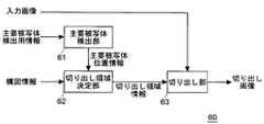
切り出し処理部60は、主要被写体検出用情報に基づいて主要被写体の入力画像中の位置を検出して主要被写体位置情報を出力する主要被写体検出部61と、主要被写体位置情報に基づいて切り出し画像の構図を決定するとともに切り出し領域を決定して切り出し領域情報を出力する切り出し領域決定部62と、切り出し領域情報に基づいて入力画像を切り出して切り出し画像を生成する切り出し部63と、を備える。 The
主要被写体検出用情報として、例えば、入力画像や入力画像に対応した音声信号、圧縮処理部8の圧縮処理時の符号化情報などを用いることができる。なお、これらの主要被写体検出用情報を用いた主要被写体の検出方法の詳細については後述する。 As the main subject detection information, for example, an input image, an audio signal corresponding to the input image, encoding information at the time of compression processing by the
また、切り出し領域決定部62には、構図情報が入力される。構図情報とは、検出された主要被写体の位置を含んだどの領域を切り出し領域として決定すべきかを指示する情報である。この構図情報は、例えば初期設定時にユーザによって入力される。なお、切り出し領域決定部62による切り出し領域の決定方法の詳細については後述する。 Further, composition information is input to the cutout
切り出し処理部60の基本動作について図面を参照して説明する。図3は、本発明の実施形態における撮像装置に備えられる切り出し処理部の基本動作を示すフローチャートである。図3に示すように、切り出し処理部60は、最初に切り出しを行う対象となる入力画像を取得する(STEP1)。 The basic operation of the
また、主要被写体検出部61は、取得した入力画像に含まれる主要被写体の検出を行う(STEP2)。特に、主要被写体検出部61は、STEP1で取得した入力画像に対応した情報である主要被写体検出用情報を用いて主要被写体の検出を行う。そして、主要被写体位置情報を出力する。 Further, the main
次に、切り出し領域決定部62が、主要被写体位置情報に基づいて切り出し領域を決定し、切り出し領域情報を出力する(STEP3)。そして、切り出し部63が、入力画像から切り出し領域情報が示す領域を切り出して、切り出し画像を生成する(STEP4)。 Next, the cutout
ここで、切り出し処理を終了する指示が入力されているか否かが確認される(STEP5)。切り出し処理を終了する指示が入力されていない場合(STEP5、NO)、STEP1に戻り、次のフレームの入力画像の取得を行う。そして、上述したSTEP2〜4の動作を行い、次のフレームの切り出し画像の生成を行う。一方、切り出し処理を終了する指示が入力されている場合は(STEP5、YES)、終了する。 Here, it is confirmed whether or not an instruction to end the clipping process has been input (STEP 5). When the instruction to end the clipping process is not input (
このような構成とすることで、検出された主要被写体を含んだ所望の構図となる画像を入力画像から切り出して、切り出し画像を生成することが可能となる。特に、入力画像に対してユーザが逐一切り出し領域を決定することを要せず、主要被写体の位置に応じた切り出し領域を決定することが可能となる。したがって、容易かつ正確に、主要被写体を含む切り出し画像を生成することが可能となる。 With such a configuration, an image having a desired composition including the detected main subject can be cut out from the input image to generate a cut-out image. In particular, it is not necessary for the user to determine a cutout region for each input image, and a cutout region corresponding to the position of the main subject can be determined. Therefore, it is possible to generate a cut-out image including the main subject easily and accurately.
<主要被写体検出部>
次に、主要被写体検出部61の検出方法の詳細について、各実施例を挙げるとともに図面を参照して説明する。<Main subject detection unit>
Next, details of the detection method of the main
[第1実施例:主要被写体検出部]
第1実施例の主要被写体検出部61では、画像情報に基づいて主要被写体を検出する。特に、図2に示した主要被写体検出用情報として入力画像を用いるとともに、この入力画像に基づいて主要被写体の検出を行う。より具体的には、入力画像に顔検出処理を施して顔領域を検出し、この顔領域の位置を主要被写体の位置とする。[First embodiment: main subject detection unit]
The main
顔検出処理方法の一例について図面を参照して説明する。図4は、第1実施例の主要被写体検出部の検出方法の一例について説明する模式図である。特に、顔検出処理方法の一例について示すものである。なお、図4に示す方法は一例に過ぎず、顔検出処理方法として既存のどのような方法を用いることとしても構わない。 An example of the face detection processing method will be described with reference to the drawings. FIG. 4 is a schematic diagram for explaining an example of the detection method of the main subject detection unit of the first embodiment. In particular, an example of a face detection processing method will be described. Note that the method shown in FIG. 4 is merely an example, and any existing method may be used as the face detection processing method.
本例では、入力画像と重みテーブルとを比較することで顔を検出することとする。重みテーブルとは、大量の教師サンプル(顔及び非顔のサンプル画像)から求められたものである。このような重みテーブルは、例えば、Adaboostと呼ばれる公知の学習方法を利用して作成することができる(Yoav Freund, Robert E. Schapire,"A decision-theoretic generalization of on-line learning and an application to boosting", European Conference on Computational Learning Theory, September 20,1995.)。このAdaboostは、適応的なブースティング学習方法の1つで、大量の教師サンプルをもとに、複数の弱識別器候補の中から識別に有効な弱識別器を複数個選択し、それらを重み付けして統合することによって高精度な識別器を実現する学習方法である。ここで、弱識別器とは、全くの偶然よりは識別能力は高いが、十分な精度を満たすほど高精度ではない識別器のことをいう。弱識別器の選択時には、既に選択した弱識別器がある場合、選択済の弱識別器によって誤認識してしまう教師サンプルに対して学習を重点化することによって、残りの弱識別器候補の中から最も効果の高い弱識別器を選択する。 In this example, the face is detected by comparing the input image with the weight table. The weight table is obtained from a large amount of teacher samples (face and non-face sample images). Such a weight table can be created using, for example, a known learning method called Adaboost (Yoav Freund, Robert E. Schapire, “A decision-theoretic generalization of on-line learning and an application to boosting” ", European Conference on Computational Learning Theory, September 20, 1995.). Adaboost is an adaptive boosting learning method. Based on a large number of teacher samples, multiple weak classifiers that are effective for classification are selected from a plurality of weak classifier candidates and weighted. It is a learning method that realizes a highly accurate classifier by integrating them. Here, a weak classifier refers to a classifier that has a higher discrimination ability than a coincidence but is not high enough to satisfy sufficient accuracy. When a weak classifier is selected, if there is a weak classifier that has already been selected, the learning is focused on the teacher sample that is misrecognized by the selected weak classifier. To select the most effective weak classifier.
図4に示すように、まず入力画像30から、例えば縮小率を0.8として縮小画像31〜35が作成されて階層化される。また、各画像30〜35において判定を行う判定領域60の大きさは、どの画像30〜35においても同じである。そして、図中の矢印で示すように、各画像上で判定領域40を左から右に移動させて水平方向の走査を行う。また、この水平走査を上方から下方に向かって行うことで、画像全体が走査される。このとき、判定領域40とマッチングする顔画像の検出が行われる。ここで、入力画像30の他に複数の縮小画像31〜35を生成することで、1種類の重みテーブルを用いて大きさが異なる顔を検出することを可能としている。また、走査順はこれに限られるものではなく、どのような順番で行っても構わない。 As shown in FIG. 4, first, reduced
マッチングは、粗い判定から順次細かい判定に移行する複数の判定ステップから成る。そして、ある判定ステップにおいて顔が検出されなかった場合には、次の判定ステップには移行せず、当該判定領域40には顔は存在しないものと判定する。全ての判定ステップにおいて顔が検出された場合にのみ、当該判定領域40に顔が存在すると判定し、判定領域を走査して次の判定領域40での判定に移行する。なお、上述の例は正面顔を検出するものであるが、横顔のサンプルなどを用いることによって主要被写体の顔の向きなどを検出することとしても構わない。 Matching is composed of a plurality of determination steps that sequentially shift from a rough determination to a fine determination. If no face is detected in a certain determination step, the process does not proceed to the next determination step, and it is determined that no face exists in the
上記の方法などによって顔検出処理を行うことにより、入力画像から主要被写体の顔が含まれる顔領域を検出することができる。そして、本実施例の主要被写体検出部61は、例えば検出された顔領域の入力画像中における位置の情報を、主要被写体位置情報として出力する。 By performing face detection processing by the above method or the like, a face area including the face of the main subject can be detected from the input image. Then, the main
本実施例の構成とすることによって、主要被写体の顔の表情を中心とした構図の切り出し画像を、容易かつ正確に得ることが可能となる。 By adopting the configuration of the present embodiment, it is possible to easily and accurately obtain a cut-out image with a composition centered on the facial expression of the main subject.
なお、顔検出によって主要被写体の顔の向きを検出し、主要被写体位置情報に含めることとしても構わない。また、主要被写体の顔の向きの検出するために、例えば、上記の検出方法の例において横顔のサンプルを用いることとしても構わない。また、特定の人物の顔をサンプルとして記録し、特定の人物を検出する顔認識処理を行っても構わない。また、検出された複数の顔領域を主要被写体位置情報として出力することとしても構わない。 The face direction of the main subject may be detected by face detection and included in the main subject position information. In order to detect the orientation of the face of the main subject, for example, a side face sample may be used in the example of the detection method described above. Further, a face recognition process may be performed in which a face of a specific person is recorded as a sample and a specific person is detected. In addition, a plurality of detected face areas may be output as main subject position information.
[第2実施例:主要被写体検出部]
第2実施例の主要被写体検出部61では、追尾処理を利用して主要被写体の位置を検出する。また、本実施例においても、図2に示した主要被写体検出用情報として入力画像を用いる。[Second Embodiment: Main Subject Detection Unit]
The main
追尾処理方法の一例について図面を参照して説明する。図5は、第2実施例の主要被写体検出部の検出方法の一例について説明する模式図である。特に、追尾処理方法の一例について説明するものである。なお、図5に示す方法は一例に過ぎず、追尾処理方法として既存のどのような方法を用いることとしても構わない。 An example of the tracking processing method will be described with reference to the drawings. FIG. 5 is a schematic diagram for explaining an example of the detection method of the main subject detection unit of the second embodiment. In particular, an example of the tracking processing method will be described. Note that the method shown in FIG. 5 is merely an example, and any existing method may be used as the tracking processing method.
図5に示す追尾処理方法では、第1実施例において説明した顔検出処理の結果を用いる。図5に示すように、本例の追尾処理方法では、最初に顔検出処理によって入力画像50から主要被写体の顔領域51を検出する。そして、顔領域51の下方(眉間から口の方向)であり顔領域51の隣接する位置に、主要被写体の胴体が含まれる胴体領域52を設定する。 In the tracking processing method shown in FIG. 5, the result of the face detection process described in the first embodiment is used. As shown in FIG. 5, in the tracking processing method of this example, the
そして、順次入力されてくる入力画像50について、順次胴体領域52を検出することで主要被写体の追尾処理を行う。このとき、胴体領域52の色(例えば、色差信号UVやRGB信号、H(Hue)S(Saturation)B(Brightness)のHの信号など、色を示す信号値)に基づいて追尾処理を行う。具体的に例えば、胴体領域52の設定時に胴体領域52の色を認識するとともに記憶し、その後に入力されてくる画像中から認識した色に類似する色を有した領域を検出することで、追尾処理を行う。 The main subject tracking process is performed by sequentially detecting the
上記の方法などによって追尾処理を行うことにより、入力画像から主要被写体の胴体領域52を検出することができる。そして、本実施例の主要被写体検出部61は、例えば検出された胴体領域52の入力画像中における位置の情報を、主要被写体位置情報として出力する。 By performing the tracking process by the above method or the like, the
本実施例の構成とすることによって、正確に主要被写体を検出し続けることが可能となる。特に、主要被写体を撮像途中で取り違えることを抑制することが可能となる。 With the configuration of the present embodiment, it is possible to continue to detect the main subject accurately. In particular, it is possible to prevent the main subject from being mistaken during the imaging.
[第3実施例:主要被写体検出部]
第3実施例の主要被写体検出部61では、圧縮処理部8の圧縮処理時における符号化情報を利用して主要被写体の位置を検出する。本実施例においては、図2に示した主要被写体検出用情報として、符号化情報を用いる。[Third embodiment: main subject detection unit]
The main
符号化情報の一例について図面を参照して説明する。図6は、第3実施例の主要被写体検出部の検出方法の一例について説明する模式図であり、特に、符号化情報について説明するものである。なお、図6(a)は入力画像の一例を示したものである。また、図6(b)は、図6(a)の入力画像を符号化した場合に得られる符号化情報の一例であり、符号量(ビットレート)の割り当てを模式的に示すものである。 An example of encoded information will be described with reference to the drawings. FIG. 6 is a schematic diagram for explaining an example of the detection method of the main subject detection unit of the third embodiment, and particularly for explaining the encoded information. FIG. 6A shows an example of the input image. FIG. 6B is an example of encoded information obtained when the input image of FIG. 6A is encoded, and schematically shows the allocation of the code amount (bit rate).
圧縮処理部8では、例えば、時刻が異なる複数の入力画像を用いてある時刻の予測画像を生成し、入力画像と予測画像との差分を符号化する圧縮処理方法が用いられる。このような圧縮処理方法を用いる場合、動きがある物体は割り当てられる符号量が他の物体よりも多いものとなる。本実施例では、入力画像の圧縮処理時に割り当てられる符号量の多少に応じて、主要被写体を検出する。 In the
図6(a)に示す入力画像70では、動く物体は幼児71のみであり、他の物体72,73は動かないものである。この場合、図6(a)に示す入力画像70を用いて得られる符号化情報74は、図6(b)に示すように、幼児71の領域のみ割り当てられる符号量が多くなる。なお、撮像装置1のぶれなどの影響により、他の物体72,73の部分においても、僅かに符号量が多くなる部分が生じ得る。 In the
圧縮処理に伴う符号化情報74を用いることにより、入力画像70から符号量が多い領域(主要被写体が含まれる領域)71を検出することができる。そして、本実施例の主要被写体検出部61は、例えば検出された符号量が多い領域71の入力画像70における位置の情報を、主要被写体位置情報として出力する。 By using the encoded
なお、図6(b)に示すように、符号量を複数の画素(例えば、8×8など)から構成されるエリア単位で算出することとしても構わないし、画素単位で算出することとしても構わない。また、圧縮処理部8で用いられる圧縮処理の方法として、MPEGやH.264などの方法を用いることとしても構わない。 As shown in FIG. 6B, the code amount may be calculated in units of areas composed of a plurality of pixels (for example, 8 × 8 or the like), or may be calculated in units of pixels. Absent. As a compression processing method used in the
本実施例の構成とすることによって、符号量が多い領域を検出するだけで主要被写体の検出を行うことが可能となる。そのため、容易に主要被写体を検出することが可能となる。さらに、動く種々の物体を主要被写体として検出することが可能となる。 By adopting the configuration of the present embodiment, it is possible to detect the main subject only by detecting a region having a large code amount. Therefore, the main subject can be easily detected. Furthermore, it is possible to detect various moving objects as the main subject.
[第4実施例:主要被写体検出部]
第4実施例の主要被写体検出部61では、AF(Auto Focus)、AE(Auto Exposure)、AWB(Auto White Balance)を行う際の指標となるそれぞれの評価値を利用して、主要被写体の位置を検出する。本実施例においては、図2に示した主要被写体検出用情報として、AF評価値、AE評価値及びAWB評価値の少なくとも1つを用いる。なお、これらの評価値は入力画像に基づいて算出される。[Fourth embodiment: main subject detection unit]
In the main
AF評価値は、例えば、入力画像の各画素の輝度値の高周波成分を、複数の画素から構成されるエリア毎に演算することによって算出することができる。そして、このAF評価値が大きいエリアでは、フォーカスが合っていることとなる。そのため、AF評価値が大きいエリアを、ユーザが撮像したいと考える主要被写体が含まれるエリアであると推定することができる。 The AF evaluation value can be calculated, for example, by calculating a high-frequency component of the luminance value of each pixel of the input image for each area composed of a plurality of pixels. In an area where the AF evaluation value is large, the focus is on. Therefore, it can be estimated that an area with a large AF evaluation value is an area including a main subject that the user wants to capture.
AE評価値は、例えば、入力画像の各画素の輝度値を、複数の画素から構成されるエリア毎に演算することによって算出することができる。そして、このAE評価値が、ある最適値に近いエリアでは露出が最適なものになっていることとなる。そのため、AE評価値が最適値に近いエリアを、ユーザが撮像したいと考える主要被写体が含まれるエリアであると推定することができる。 The AE evaluation value can be calculated, for example, by calculating the luminance value of each pixel of the input image for each area composed of a plurality of pixels. In the area where the AE evaluation value is close to a certain optimum value, the exposure is optimum. Therefore, it can be estimated that the area where the AE evaluation value is close to the optimum value is the area including the main subject that the user wants to image.
AWB評価値は、例えば、入力画像の各画素の各成分値(例えば、RGBの各値や色差信号UVの各値)を、複数の画素から構成されるエリア毎に演算することによって算出することができる。また例えば、それぞれのエリア内における成分値の割合から色温度を算出し、これによってAWB評価値を表現することも可能である。そして、このAWB評価値が、ある最適値に近いエリアではホワイトバランスが最適なものになっていることとなる。そのため、AWB評価値が最適値に近いエリアを、ユーザが撮像したいと考える主要被写体が含まれるエリアであると推定することができる。 The AWB evaluation value is calculated, for example, by calculating each component value of each pixel of the input image (for example, each value of RGB or each value of the color difference signal UV) for each area composed of a plurality of pixels. Can do. Further, for example, it is possible to calculate the color temperature from the ratio of the component values in each area and thereby express the AWB evaluation value. In the area where the AWB evaluation value is close to a certain optimum value, the white balance is optimum. Therefore, it can be estimated that the area where the AWB evaluation value is close to the optimum value is the area including the main subject that the user wants to image.
上記の少なくとも一つの評価値を用いることにより、入力画像から主要被写体が含まれるエリアを検出することができる。そして、本実施例の主要被写体検出部61は、例えば、検出されたエリアの入力画像における位置の情報を、主要被写体位置情報として出力する。 By using the at least one evaluation value, an area including the main subject can be detected from the input image. Then, the main
本実施例の構成とすることによって、入力画像の調整を行うために必要とされるそれぞれの評価値を利用して、主要被写体の検出を行うことが可能となる。そのため、容易に主要被写体を検出することが可能となる。また、種々の物体を主要被写体として検出することが可能となる。 By adopting the configuration of the present embodiment, it is possible to detect the main subject by using the respective evaluation values necessary for adjusting the input image. Therefore, the main subject can be easily detected. In addition, various objects can be detected as the main subject.
なお、上記の各評価値を複数の画素から構成されるエリア単位で算出することとしても構わないし、画素単位で算出することとしても構わない。 Note that each of the evaluation values may be calculated in units of areas composed of a plurality of pixels, or may be calculated in units of pixels.
[第5実施例:主要被写体検出部]
第5実施例の主要被写体検出部61では、音声信号を利用して主要被写体の位置を検出する。本実施例においては、図2に示した主要被写体検出用情報として、入力画像に対応する音声信号を用いる。入力画像に対応する音声信号とは、例えば、入力画像の撮像時に集音されて生成された音声信号を示すものであり、後段の圧縮処理部8において入力画像と時間的に関連付けられる音声信号である。[Fifth embodiment: main subject detection unit]
The main
本実施例による主要被写体検出方法の一例について、図面を参照して説明する。図7は、第5実施例の主要被写体検出部の検出方法の一例について説明する模式図である。特に、主要被写体から到来する音声を集音する場合の一例を示したものである。なお、以下における本実施例の説明においては、図1で示した集音部5が、少なくとも2つのマイクを備えたマイクアレイであるものとする。 An example of a main subject detection method according to the present embodiment will be described with reference to the drawings. FIG. 7 is a schematic diagram for explaining an example of the detection method of the main subject detection unit of the fifth embodiment. In particular, an example of collecting sound coming from a main subject is shown. In the following description of the present embodiment, it is assumed that the
図7に示すように、主要被写体が発してマイク5a,5bに到来する音声は、それぞれのマイク5a,5bによって集音されて音声信号へと変換される。このとき、主要被写体とマイク5a,5bとを結んだ直線と、マイク5a,5bを結んだ直線とが成す到来角度θに応じて、マイク5a,5bに到来する音声に時間差が生じる。なお、マイク5a,5bの間隔Dは、マイク5a,5bと主要被写体との距離よりも十分小さいものとし、主要被写体とマイク5a,5bとを結んだそれぞれの直線が略平行になるものとする。また、本例における到来角度θは、マイク5a,5bを結んだ直線と主要被写体とマイク5a,5bとを結んだ直線とが成す角度とする。 As shown in FIG. 7, the voices emitted from the main subject and arriving at the
この場合、例えば主要被写体からマイク5a,5bに到達する音声の時間差(遅延時間)を算出することで、到来角度θを算出することができる。特に、遅延距離dl=D×cos(θ)を、音速c(≒344m/sec)で除算した値が遅延時間dtとなるため、遅延時間dtに基づいて到来角度θを算出することができる。なお、遅延時間dtは例えば、マイク5a,5bから得られるそれぞれの音声信号を時間軸上で比較する(例えば、パターンマッチングを行う)ことによって、算出することができる。 In this case, for example, the arrival angle θ can be calculated by calculating the time difference (delay time) of the sound that reaches the
また、マイク5a,5bから得られるそれぞれの音声信号を周波数軸上で比較し、得られる位相差に基づいて到来方向を算出することも可能である。例えば、下記式(1)に示すように、マイク5a,5bから得られる音声信号の演算を行うことで、位相差φを算出する。下記式(1)において、spec_r(i)は、マイク5aで集音されて得られる音声信号の周波数帯域iの成分である。また、spec_l(i)は、マイク5bで集音されて得られる音声信号の周波数帯域iの成分である。なお、それぞれの音声信号の周波数帯域iの成分を算出するために、それぞれの音声信号に対してFFT(Fast Fourier Transform)処理を施すこととしても構わない。 It is also possible to compare the respective audio signals obtained from the

図7に示すような0°≦θ<90°の場合であれば、位相差φが正の値となる。一方、90°<θ≦180°の場合であれば、位相差φは負の値となる。 When 0 ° ≦ θ <90 ° as shown in FIG. 7, the phase difference φ is a positive value. On the other hand, if 90 ° <θ ≦ 180 °, the phase difference φ is a negative value.
複数のマイク5a,5bから得られる音声信号を用いることにより、主要被写体が存在する方向を検出することが可能となる。そして、本実施例の主要被写体検出部61は、例えば、検出された主要被写体が存在する方向に基づいて求められる、入力画像中の主要被写体の位置の情報を、主要被写体位置情報として出力する。 By using audio signals obtained from the plurality of
本実施例の構成とすることによって、音声信号に基づいて主要被写体の検出を行うことが可能となる。そのため、音を発する種々の物体を主要被写体として検出することが可能となる。 With the configuration of the present embodiment, it is possible to detect the main subject based on the audio signal. Therefore, various objects that emit sound can be detected as the main subject.
なお、一例として集音部5に備えられる2つのマイク5a,5bから得られる2つの音声信号を用いる場合について説明したが、用いる音声信号は2つに限られない。3つ以上のマイクから得られる3つ以上の音声信号を用いることも可能である。用いる音声信号を増やすと、より正確に主要被写体が存在する方向を特定することができるため、好ましい。 In addition, although the case where two audio | voice signals obtained from two
[変形例:主要被写体検出部]
なお、主要被写体位置情報が、入力画像のある領域(例えば、顔領域)を示すものとしても構わないし、ある点(例えば、顔領域の中心座標)を示すものとしても構わない。[Modification: Main subject detection unit]
The main subject position information may indicate a certain area (for example, a face area) of the input image, or may indicate a certain point (for example, the center coordinates of the face area).
また、上述したそれぞれの実施例の主要被写体検出部は、単独で用いるのみならず組み合わせて用いることも可能である。例えば、上述したそれぞれの方法によって得られる複数の検出結果に対して重み付けを行うとともに合成し、主要被写体位置情報として出力することとしても構わない。このように構成すると、様々な方法で主要被写体の検出が行われるため、より正確に主要被写体を検出することが可能となる。 In addition, the main subject detection units of the embodiments described above can be used not only independently but also in combination. For example, a plurality of detection results obtained by the respective methods described above may be weighted and combined and output as main subject position information. With this configuration, since the main subject is detected by various methods, the main subject can be detected more accurately.
また、それぞれの検出方法に優先度を設け、優先度が高い検出方法では検出不能である場合に、優先度が低い検出方法を用いて主要被写体の検出を行い、得られた検出結果を主要被写体位置情報として出力することとしても構わない。 In addition, when a priority is set for each detection method and detection is impossible with a detection method with high priority, the main subject is detected using the detection method with low priority, and the obtained detection result is used as the main subject. The position information may be output.
<切り出し領域決定部>
次に、切り出し領域決定部62の切り出し方法の詳細について、各実施例を挙げるとともに図面を参照して説明する。なお、以下では説明の具体化のため、第1実施例の主要被写体検出部61によって出力される主要被写体位置情報(顔領域)に基づいて、切り出し領域情報を設定し、出力する場合について説明することとする。<Cutout area determination unit>
Next, details of the cutout method of the cutout
[第1実施例:切り出し領域決定部]
第1実施例の切り出し領域決定部62は、ユーザの操作によって入力される構図情報に基づいて、切り出し領域を決定する。この構図情報は、例えば、画像記録開始前のプレビュー画像の表示中などに入力される。[First embodiment: Cutout area determination unit]
The cutout
本実施例の切り出し領域決定部62の、切り出し領域の決定方法の一例について、図面を参照して説明する。図8は、第1実施例の切り出し領域決定部の切り出し方法の一例について説明する模式図である。図8(a),(b)では、入力画像の座標を、左上(0,0)、右上(25,0)、左下(0,11)、右下(25,11)とする。 An example of a cutout region determination method performed by the cutout
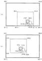
図8(a)に示す例では、顔領域の座標が、左上(14,7)、右上(18,7)、左下(14,10)、右下(18,10)であるものとする。また、切り出し領域の座標が、左上(9,4)、右上(21,4)、左下(9,11)、右下(21,11)であるものとする。この場合、切り出し領域と顔領域との位置関係、例えば(切り出し領域の座標)―(顔領域の座標)は、左上(−5,−3)、右上(3,−3)、左下(−5,1)、右下(3,1)となる。 In the example shown in FIG. 8A, the coordinates of the face region are assumed to be upper left (14, 7), upper right (18, 7), lower left (14, 10), and lower right (18, 10). Further, the coordinates of the cutout region are assumed to be upper left (9, 4), upper right (21, 4), lower left (9, 11), and lower right (21, 11). In this case, the positional relationship between the cut-out area and the face area, for example, (coordinate of cut-out area) − (coordinate of face area) is upper left (−5, −3), upper right (3, −3), lower left (−5). , 1), lower right (3, 1).
また、図8(b)に示す例では、顔領域の座標が、左上(7,5)、右上(11,5)、左下(7,8)、右下(11,8)であるものとする。また、切り出し領域の座標が、左上(2,2)、右上(14,2)、左下(2,9)、右下(14,9)であるものとする。この場合、切り出し領域と顔領域との位置関係、例えば(切り出し領域の座標)―(顔領域の座標)は、図8(a)と同様に、左上(−5,−3)、右上(3,−3)、左下(−5,1)、右下(3,1)となる。 Further, in the example shown in FIG. 8B, the coordinates of the face area are upper left (7, 5), upper right (11, 5), lower left (7, 8), lower right (11, 8). To do. The coordinates of the cutout region are assumed to be upper left (2, 2), upper right (14, 2), lower left (2, 9), and lower right (14, 9). In this case, the positional relationship between the cutout area and the face area, for example, (coordinate of the cutout area) − (coordinates of the face area) is the same as in FIG. 8A, in the upper left (−5, −3), upper right (3 , -3), lower left (-5, 1), lower right (3, 1).
図8(a),(b)に示した例のように、本実施例では、主要被写体位置情報(例えば顔領域)が示す位置と切り出し領域の位置との関係が、主要被写体の位置に関わらず設定した位置関係(構図情報)で維持される。そして、切り出し部63において、入力画像から切り出し領域のみが切り出され、切り出し画像が得られる。 As in the example shown in FIGS. 8A and 8B, in this embodiment, the relationship between the position indicated by the main subject position information (for example, the face area) and the position of the cutout area is related to the position of the main subject. It is maintained with the set positional relationship (composition information). In the
以上のように構成することによって、ユーザが所望する構図を維持した切り出し画像を容易に得ることが可能となる。 By configuring as described above, it is possible to easily obtain a cut-out image that maintains the composition desired by the user.
なお、ユーザが構図を決定する際に、撮像装置1に備えられる操作部16が用いられることとしても構わない。また、操作部16をタッチパネルとしても構わないし、方向キーなどのボタンとしても構わない。 Note that the
[第2実施例:切り出し領域決定部]
第2実施例の切り出し領域決定部62も第1実施例と同様に、ユーザの操作によって入力される構図情報に基づいて、切り出し領域を決定する。ただし、本実施例では、撮像中に構図情報を変更可能であるものとする。[Second Embodiment: Cutout Area Determination Unit]
Similarly to the first embodiment, the cutout
本実施例の切り出し領域決定部62の、切り出し領域の決定方法の一例について、図面を参照して説明する。図9は、第2実施例の切り出し領域決定部の切り出し方法の一例について説明する模式図であり、第1実施例について説明した図8に相当するものである。また、図9(a)〜(c)についても、入力画像の座標を、左上(0,0)、右上(25,0)、左下(0,11)、右下(25,11)とする。 An example of a cutout region determination method performed by the cutout
図9(a)は、図8(a)と同様の状態を示したものである。即ち、顔領域の座標が、左上(14,7)、右上(18,7)、左下(14,10)、右下(18,10)であり、切り出し領域の座標が、左上(9,4)、右上(21,4)、左下(9,11)、右下(21,11)である。また、切り出し領域と顔領域との位置関係、例えば(切り出し領域の座標)―(顔領域の座標)は、左上(−5,−3)、右上(3,−3)、左下(−5,1)、右下(3,1)となる。また、図9(a)では、主要被写体の進行方向が左向きであることとする。 FIG. 9A shows a state similar to that in FIG. That is, the coordinates of the face area are upper left (14, 7), upper right (18, 7), lower left (14, 10), lower right (18, 10), and the coordinates of the cutout area are upper left (9, 4). ), Upper right (21, 4), lower left (9, 11), and lower right (21, 11). Further, the positional relationship between the cutout area and the face area, for example, (coordinate of the cutout area) − (coordinates of the face area) is upper left (−5, −3), upper right (3, −3), lower left (−5, 1), lower right (3, 1). Further, in FIG. 9A, it is assumed that the traveling direction of the main subject is leftward.
図9(b)は、主要被写体の進行方向が右向きとなる場合である。なお、顔領域の位置は図9(a)と同じ位置とする。そのため、切り出し領域の座標は図9(a)に示す場合と同様のものとなる。図9(a)に示す場合、ユーザは、主要被写体が左方に進行している場合を考えて構図を決定している。そのため、図9(b)に示すように、主要被写体が進行方向を変えた場合、ユーザが構図を変更したいと考える場合がある。 FIG. 9B shows a case where the main subject travels in the right direction. Note that the position of the face area is the same as that in FIG. For this reason, the coordinates of the cutout region are the same as those shown in FIG. In the case illustrated in FIG. 9A, the user determines the composition considering the case where the main subject is moving leftward. Therefore, as shown in FIG. 9B, when the main subject changes the traveling direction, the user may want to change the composition.
そこで、本実施例では、構図(主要被写体の位置と切り出し領域との位置関係)を撮像中に変更可能な構成としている。構図の変更は、例えば、図9(b)に示す状態となった場合などに行われ得る。構図の変更が行われる場合、それまで設定されていた構図が解除される。このとき、例えば、構図を解除する旨の構図情報が切り出し領域決定部62に入力されたり、変更直前まで入力されていた構図情報とは異なる構図情報が切り出し領域決定部62に入力されたりする。 Therefore, in this embodiment, the composition (positional relationship between the position of the main subject and the cutout area) can be changed during imaging. The composition can be changed, for example, when the state shown in FIG. When the composition is changed, the composition set up to that point is canceled. At this time, for example, composition information for canceling the composition is input to the cutout
その後、ユーザによって新たな構図が決定されると、新たな構図を示す構図情報が切り出し領域決定部62に入力される。そして、切り出し領域決定部62は、図9(c)に示すように、新たな構図となる切り出し領域を決定する。図9(c)に示す例では、顔領域の座標が、左上(14,7)、右上(18,7)、左下(14,10)、右下(18,10)であるものとする。また、切り出し領域の座標が、左上(11,4)、右上(23,4)、左下(11,11)、右下(23,11)であるものとする。この場合、切り出し領域と顔領域との位置関係、例えば(切り出し領域の座標)―(顔領域の座標)は、図9(a)とは異なり、左上(−3,−3)、右上(5,−3)、左下(−3,1)、右下(5,1)となる。 Thereafter, when a new composition is determined by the user, composition information indicating the new composition is input to the cutout
以上のように構成すると、主要被写体の状態に応じて、ユーザが望む構図を自由に決定することが可能となる。そのため、不自然な構図となる切り出し画像が生成され続けることを抑制することが可能となる。 With the configuration described above, it is possible to freely determine the composition desired by the user according to the state of the main subject. For this reason, it is possible to suppress the generation of a cutout image having an unnatural composition.
なお、構図情報を解除した後、新たな構図情報を設定するまでの間に使用される構図情報を、解除前と同様の構図情報としても構わないし、予め設定しておいた解除中用の構図情報としても構わない。また、ユーザが構図を決定する際に、撮像装置1に備えられる操作部16が用いられることとしても構わない。さらに、操作部16をタッチパネルとしても構わないし、方向キーなどのボタンとしても構わない。 Note that the composition information used after the composition information is released and before the new composition information is set may be the same composition information as before the release, or the composition for release that has been set in advance. It does not matter as information. Further, when the user determines the composition, the
[第3実施例:切り出し領域決定部]
第3実施例の切り出し領域決定部62は、入力される主要被写体位置情報に基づいて、最適となる構図を自動的に決定する。そのため、ユーザの指示に従って構図を決定したり変更したりする第1及び第2実施例とは、この点において異なる。[Third embodiment: clipping region determination unit]
The cutout
本実施例の切り出し領域決定部62の、切り出し領域の決定方法の一例について、図面を参照して説明する。図10は、第3実施例の切り出し領域決定部の切り出し方法の一例について説明する模式図であり、第1実施例について説明した図8に相当するものである。また、図10(a),(b)についても、入力画像の座標を、左上(0,0)、右上(25,0)、左下(0,11)、右下(25,11)とする。 An example of a cutout region determination method performed by the cutout
図10(a),(b)に示すように、本実施例では主要被写体位置情報に、主要被写体の位置だけでなく主要被写体の状態を示す情報(例えば、顔の向き)が含まれるものとする。なお、図10(a),(b)において、主要被写体の顔の向きを黒い矢印で表現する。 As shown in FIGS. 10A and 10B, in this embodiment, the main subject position information includes not only the position of the main subject but also information indicating the state of the main subject (for example, the face orientation). To do. In FIGS. 10A and 10B, the face direction of the main subject is represented by a black arrow.
図10(a)は、図8(a)と同様の状態を示したものである。即ち、顔領域の座標が、左上(14,7)、右上(18,7)、左下(14,10)、右下(18,10)であり、切り出し領域の座標が、左上(9,4)、右上(21,4)、左下(9,11)、右下(21,11)である。また、切り出し領域と顔領域との位置関係、例えば(切り出し領域の座標)―(顔領域の座標)は、左上(−5,−3)、右上(3,−3)、左下(−5,1)、右下(3,1)となる。ただし、図10(a)では、主要被写体の顔の向きが左向きであると検出されているものとする。 FIG. 10A shows a state similar to that in FIG. That is, the coordinates of the face area are upper left (14, 7), upper right (18, 7), lower left (14, 10), lower right (18, 10), and the coordinates of the cutout area are upper left (9, 4). ), Upper right (21, 4), lower left (9, 11), and lower right (21, 11). Further, the positional relationship between the cutout area and the face area, for example, (coordinate of the cutout area) − (coordinates of the face area) is upper left (−5, −3), upper right (3, −3), lower left (−5, 1), lower right (3, 1). However, in FIG. 10A, it is assumed that the face direction of the main subject is detected to be leftward.
一方、図10(b)に示す例は、主要被写体の顔の向きが左向きから右向きへと変化した場合について示したものである。図10(b)に示す場合においても、顔領域の座標が、左上(14,7)、右上(18,7)、左下(14,10)、右下(18,10)であり、図10(a)に示す位置と同じ位置にあるものとする。 On the other hand, the example shown in FIG. 10B shows a case where the face direction of the main subject changes from left to right. Also in the case shown in FIG. 10B, the coordinates of the face area are the upper left (14, 7), the upper right (18, 7), the lower left (14, 10), and the lower right (18, 10). It shall be in the same position as the position shown in (a).
そして、図10(b)の場合に、切り出し領域決定部62によって決定される切り出し領域の座標が、左上(11,4)、右上(23,4)、左下(11,11)、右下(23,11)とする。また、切り出し領域と顔領域との位置関係、例えば(切り出し領域の座標)―(顔領域の座標)は、図10(a)とは異なり、左上(−3,−3)、右上(5,−3)、左下(−3,1)、右下(5,1)となる。 In the case of FIG. 10B, the coordinates of the cutout area determined by the cutout
図10(a),(b)のそれぞれは、切り出し領域中の顔領域の位置が顔の向きと逆方向に寄ったものとなるように、切り出し領域が設定される場合について示したものである。なお、このような設定は、ユーザによって成されるものであっても構わないし、予め撮像装置に記録されているものであっても構わない。 Each of FIGS. 10A and 10B shows a case where the cutout region is set so that the position of the face region in the cutout region is shifted in the direction opposite to the face direction. . Such a setting may be made by the user or may be recorded in advance in the imaging apparatus.
以上のように構成すると、主要被写体の状態が変化した場合に、容易に構図の変更を行うことが可能となる。特に、第2実施例のようにユーザが手動で構図を設定し直す手間を省くことが可能となる。さらに、構図の変更に時間がかからないため、変更に伴って不自然な構図の切り出し画像が生成されることを抑制することが可能となる。 With the configuration described above, it is possible to easily change the composition when the state of the main subject changes. In particular, it is possible to save the user from manually resetting the composition as in the second embodiment. Furthermore, since it does not take time to change the composition, it is possible to suppress generation of a cut-out image having an unnatural composition accompanying the change.
また、切り出し領域中の主要被写体の位置が、顔の向きと逆方向に寄ったものとなるように、切り出し領域を決定することとすると、主要被写体が注目しているであろう領域を切り出し画像内に含めることが可能となる。 In addition, when the cutout area is determined so that the position of the main subject in the cutout area is shifted in the direction opposite to the face direction, the area that the main subject will be paying attention to is extracted. It becomes possible to include in.
なお、上記の例では、主要被写体の状態を示す情報として顔の向きが用いられる場合について説明したが、主要被写体の状態を示す情報として適用可能な情報はこの限りではない。例えば、主要被写体の目線の向きでも構わないし、主要被写体の動きベクトルでも構わない。なお、主要被写体の目線の向きを用いる場合、顔の向きを用いる場合と同様の動作を行うこととしても構わない。また、主要被写体の動きベクトルを用いる場合について、以下に図面を参照して説明する。 In the above example, the case where the face orientation is used as information indicating the state of the main subject has been described, but information applicable as information indicating the state of the main subject is not limited to this. For example, the direction of the line of sight of the main subject or the motion vector of the main subject may be used. Note that when using the eye direction of the main subject, the same operation as when using the face direction may be performed. The case of using the motion vector of the main subject will be described below with reference to the drawings.
図11は、第3実施例の切り出し領域決定部の切り出し方法の別例について説明する模式図であり、本実施例の一例について示した図10に相当するものである。また、図11についても、入力画像の座標を、左上(0,0)、右上(25,0)、左下(0,11)、右下(25,11)とし、顔領域の座標が、左上(14,7)、右上(18,7)、左下(14,10)、右下(18,10)であるものとする。 FIG. 11 is a schematic diagram for explaining another example of the cutout method of the cutout area determination unit of the third embodiment, and corresponds to FIG. 10 showing an example of this embodiment. Also in FIG. 11, the coordinates of the input image are the upper left (0, 0), upper right (25, 0), lower left (0, 11), lower right (25, 11), and the coordinates of the face area are the upper left. (14, 7), upper right (18, 7), lower left (14, 10), lower right (18, 10).
図11中のハッチングを付した部分は、現在の入力画像より前に処理された入力画像の主要被写体を示したものである。そして、現在の入力画像と前の入力画像とを比較することで、図示するような動きベクトルが算出される。この動きベクトルの算出方法として、既存のどのような方法を用いても構わない。 The hatched portion in FIG. 11 shows the main subject of the input image processed before the current input image. Then, a motion vector as shown in the figure is calculated by comparing the current input image with the previous input image. Any existing method may be used as the motion vector calculation method.
例えば、ブロックマッチング法や代表点マッチング法などの種々のマッチング方法を利用することで、動きベクトルを算出しても構わない。なお、主要被写体とその近傍の画素の画素値の変動を利用して、動きベクトルを算出することとしても構わない。また、エリア毎に動きベクトルを算出することとしても構わない。また、主要被写体検出用情報が複数の入力画像であり、主要被写体検出部61が動きベクトルを算出するとともに、主要被写体位置情報に動きベクトルを含ませる構成としても構わない(図2参照)。 For example, the motion vector may be calculated by using various matching methods such as a block matching method and a representative point matching method. Note that the motion vector may be calculated using the fluctuations in the pixel values of the main subject and the neighboring pixels. Also, the motion vector may be calculated for each area. The main subject detection information may be a plurality of input images, and the main
図11に示すように、本例では、切り出し領域中の主要被写体の位置(顔領域)が、動きベクトルが示す方向側と逆方向に寄ったものとなるように、切り出し領域が決定される。例えば切り出し領域の座標が、左上(11,4)、右上(23,4)、左下(11,11)、右下(23,11)となり、切り出し領域と顔領域との位置関係、例えば(切り出し領域の座標)―(顔領域の座標)は、左上(−5,−3)、右上(3,−3)、左下(−5,1)、右下(3,1)となる。 As shown in FIG. 11, in this example, the cutout region is determined so that the position of the main subject (face region) in the cutout region is shifted in the direction opposite to the direction indicated by the motion vector. For example, the coordinates of the cutout area are upper left (11, 4), upper right (23, 4), lower left (11, 11), lower right (23, 11), and the positional relationship between the cutout area and the face area, for example, (cutout) Area coordinates)-(face area coordinates) are upper left (-5, -3), upper right (3, -3), lower left (-5, 1), and lower right (3, 1).
このように構成しても、主要被写体の状態の変化に応じて容易かつ自動的に構図の変更を行うことが可能となる。また、主要被写体の位置が動きベクトルが示す方向側と逆方向に寄ったものとなるように、切り出し領域を決定することによって、主要被写体がどこに向かってどのように移動しているかを明確化することが可能となる。 Even with this configuration, it is possible to easily and automatically change the composition in accordance with changes in the state of the main subject. In addition, clarifying where and how the main subject is moving by determining the cutout area so that the position of the main subject is shifted in the direction opposite to the direction indicated by the motion vector. It becomes possible.
また、構図の変更にヒステリシス特性を持たせ、ある一定時間内は構図が変更されないこととしても構わない。このように構成すると、主要被写体の状態によって頻繁に構図が変更されることによって、不自然な切り出し画像が生成されることを抑制することが可能となる。 Further, the composition change may have hysteresis characteristics so that the composition is not changed within a certain period of time. If comprised in this way, it will become possible to suppress that an unnatural cut-out image is produced | generated by changing a composition frequently with the state of a main to-be-photographed object.
[変形例:切り出し領域決定部]
なお、上述した各実施例について、座標を画素単位としても構わないし、エリア単位としても構わない。また、構図情報を、切り出し領域の位置と主要被写体位置情報が示す位置との座標の差としても構わないし、主要被写体位置情報が示す領域を上下左右方向に拡大するそれぞれの割合としても構わない。[Modification: Cutout area determination unit]
In each of the embodiments described above, the coordinates may be in pixel units or area units. Further, the composition information may be a coordinate difference between the position of the cut-out area and the position indicated by the main subject position information, or may be the respective ratios for expanding the area indicated by the main subject position information in the vertical and horizontal directions.
また、主要被写体が入力画像の端に移動し、構図情報にしたがって決定される切り出し領域の位置が入力画像の外側に出る場合、構図情報を変更して、切り出し領域が入力画像内に入るようにしても構わない。また、撮像装置1のズーム倍率を小さくする制御を行うなどして入力画像の画角を広げ、主要被写体の位置が入力画像の端から離れるように制御しても構わない。 In addition, when the main subject moves to the edge of the input image and the position of the cutout area determined according to the composition information is outside the input image, the composition information is changed so that the cutout area enters the input image. It doesn't matter. In addition, the angle of view of the input image may be widened by performing control to reduce the zoom magnification of the
また、主要被写体位置情報が示す主要被写体の領域の大きさが可変となるとき、決定される切り出し領域の大きさが、この主要被写体の領域の大きさに応じて増減することとしても構わない。そして、切り出し部63が、切り出し画像の拡大処理(例えば、画素の補間処理)や、縮小処理(例えば、画素の間引き処理や加算平均化処理)を行い、所定の大きさの画像となるように制御することとしても構わない。また、この場合の構図情報を、主要被写体位置情報が示す領域を上下左右方向に拡大するそれぞれの割合としても構わない。 In addition, when the size of the main subject area indicated by the main subject position information is variable, the size of the cutout area determined may be increased or decreased according to the size of the main subject area. Then, the
また、上述したそれぞれの実施例の切り出し領域決定部62は、単独で用いるのみならず組み合わせて用いることも可能である。例えば、第2実施例の切り出し領域決定部62において、ユーザが構図の解除を行って新たな構図を設定するまでの間に、第3実施例の切り出し領域決定部62によって決定された構図を採用することとしても構わない。 In addition, the cut-out
<<主要被写体が複数の物体から成る場合への適用>>
上述の各実施例では、主要被写体が一つの物体から成る場合について中心に述べたが、複数の物体(以下、構成被写体とする)から成る場合であっても同様に、切り出し画像を生成することが可能である。以下、主要被写体が複数の構成被写体から成る場合においても切り出し画像を生成し得る切り出し処理部の構成及び動作について、具体的に説明する。<< Applicable when the main subject consists of multiple objects >>
In each of the above-described embodiments, the case where the main subject is composed of a single object has been mainly described. However, a cut-out image is generated in the same manner even when the main subject is composed of a plurality of objects (hereinafter referred to as constituent subjects). Is possible. Hereinafter, the configuration and operation of the cutout processing unit that can generate a cutout image even when the main subject includes a plurality of constituent subjects will be described in detail.
最初に、この切り出し処理部の構成例について図面を参照して説明する。図12は、主要被写体が複数の構成被写体を備える場合にも切り出し画像を生成し得る切り出し処理部の構成の一例を示すブロック図であり、基本構成について示した図2に相当するものである。なお、図2と同様の構成となる部分には同様の符号を付し、その詳細な説明については省略する。 First, a configuration example of the cutout processing unit will be described with reference to the drawings. FIG. 12 is a block diagram illustrating an example of a configuration of a cutout processing unit that can generate a cutout image even when the main subject includes a plurality of constituent subjects, and corresponds to FIG. 2 illustrating the basic configuration. Note that parts having the same configuration as in FIG. 2 are denoted by the same reference numerals, and detailed description thereof is omitted.
図13に示すように、本例の切り出し処理部60bは、主要被写体検出部61bと、切り出し領域決定部62と、切り出し部63と、を備える。ただし、主要被写体検出部61bが、主要被写体検出用情報に基づいて一つの構成被写体の入力画像中の位置をそれぞれ検出して第1〜第n構成被写体位置情報をそれぞれ出力する第1〜第n構成被写体検出部611〜61nと、第1〜第n構成被写体位置情報を統計処理して主要被写体位置情報を出力する統計処理部61xと、を備える。なお、nは2以上の整数である。 As illustrated in FIG. 13, the
第1〜第n構成被写体検出部611〜61nは、上述した図2の主要被写体検出部61と同様の検出動作を行い、それぞれが異なる構成被写体の位置を検出する。そして、検出結果を第1〜第n構成被写体位置情報として出力する。なお、上述のように第1〜第n構成被写体検出部611〜61nのそれぞれは、構成被写体の顔や目線の向き、動きベクトルなどの方向に関する情報も検出し得る。また、図12では概念的に示すために、第1〜第n構成被写体検出部611〜61nを分離して示しているが、複数の構成被写体を同時に検出可能な1つのブロック(プログラム)としても構わない。 The first to n-th constituent
統計処理部61xは、第1〜第n構成被写体検出部611〜61nのそれぞれから出力される第1〜第n構成被写体位置情報を統計処理することで、入力画像中から検出された複数の構成被写体全体(即ち、主要被写体)の入力画像中の位置を示す主要被写体位置情報を算出し、出力する。なお、上述のように第1〜第n構成被写体位置情報に、構成被写体の顔や目線の向き、動きベクトルなどの方向に関する情報が含まれる場合、これらの情報に対しても統計処理を行い、得られる主要被写体の方向に関する情報を主要被写体位置情報に含ませることとしても構わない。 The
したがって、主要被写体位置情報には、入力画像中の主要被写体の位置(例えば、検出された全ての構成被写体を包含する矩形領域の位置や、構成被写体の平均位置など)の情報が含まれ得る。また、主要被写体の顔や目線の向き(例えば、構成被写体の顔や目線の平均向き)の情報、主要被写体の動きベクトルの方向や大きさ(例えば、構成被写体の動きベクトルの平均方向や平均の大きさ)なども含まれ得る。 Therefore, the main subject position information can include information on the position of the main subject in the input image (for example, the position of a rectangular area including all detected constituent subjects, the average position of the constituent subjects, etc.). Also, information on the orientation and direction of the main subject's face and eyes (for example, the average orientation of the faces and eyes of the constituent subjects), the direction and size of the motion vector of the main subject (eg, the average direction and average of the motion vectors of the constituent subjects) Size) and the like.
切り出し領域決定部62は、上述した図2の切り出し領域決定部62と同様に、主要被写体位置情報に基づいて切り出し領域を決定して切り出し領域情報を出力する。そして、切り出し部63が、入力画像から切り出し領域情報が示す切り出し領域を切り出して、切り出し画像を生成する。 The cutout
次に、切り出し領域決定部62による切り出し領域の決定方法の具体例について、図面を参照して説明する。図13〜図15は、複数の主要被写体に基づいて決定される切り出し領域の一例を示す模式図である。 Next, a specific example of a method for determining a cutout region by the cutout
(具体例1)
図13は、複数の構成被写体の顔や目線の向きが略等しい方向となる場合(例えば、合唱時)について示したものである。また、図中に入力画像100と、主要被写体位置情報によって示される主要被写体位置110と、切り出し領域120と、を示している。(Specific example 1)
FIG. 13 shows a case where the directions of faces and eyes of a plurality of constituent subjects are substantially equal (for example, at the time of chorus). Further, in the figure, an
第1〜第n構成被写体検出部611〜61nは、主要被写体検出用情報である入力画像に対して顔検出を行うことで、構成被写体の検出を行う。また、統計処理部61xが、この検出結果である第1〜第n構成被写体位置情報に基づいて主要被写体位置110を算出する。そして、切り出し領域決定部62が、主要被写体位置110と主要被写体の顔の向きとに基づいて切り出し領域120を決定する。 The first to n-th constituent
本具体例では、主要被写体の顔や目線の向きが特定の方向(図中の黒塗りの矢印、左方向)として算出される。そこで、切り出し領域決定部62は、主要被写体位置110が主要被写体の顔や目線の向き(図中左方向)とは逆方向(図中右方向)に寄った位置になるように、切り出し領域120を決定する。このとき、全ての構成被写体が含まれるように、切り出し領域120を決定しても構わない。 In this specific example, the face and eye direction of the main subject are calculated as a specific direction (black arrow in the figure, left direction). Therefore, the cutout
このように構成すると、容易かつ自動的に主要被写体(複数の構成被写体)の状態に応じた構図となる切り出し領域120を決定することが可能となる。特に、構成被写体が注目しているであろう領域を明確化した切り出し領域120を決定することが可能となる。 With this configuration, it is possible to easily and automatically determine the
なお、本具体例において、第1〜第n構成被写体検出部611〜61nが、上述の第1実施例の主要被写体検出部61と同様の検出方法を用いて、それぞれの主要被写体の検出を行うこととしても構わない。また、切り出し領域決定部62が、上述の第3実施例の切り出し領域決定部62と同様の決定方法を用いて、切り出し領域を決定することとしても構わない(図10参照)。 In this specific example, the first to nth component
(具体例2)
具体例1において、それぞれの構成被写体の顔や目線の向きにばらつきがあり(相関が所定の大きさ以下)、主要被写体の顔や目線の向きを特定の方向として算出することが困難である(算出される方向の信頼性が低い)場合における切り出し領域の決定方法の一例について、本具体例で説明する。図14は、構成被写体の顔や目線の向きにばらつきがある場合(例えば、玉入れ時)について示したものである。また、図中に入力画像101と、主要被写体位置情報によって示される主要被写体位置111と、切り出し領域121と、を示している。(Specific example 2)
In specific example 1, there are variations in the face and eye direction of each constituent subject (correlation is not more than a predetermined magnitude), and it is difficult to calculate the face and eye direction of the main subject as a specific direction ( An example of a method for determining a cutout region in the case where the reliability of the calculated direction is low) will be described in this specific example. FIG. 14 shows the case where the orientation of the face and line of sight of the constituent subject varies (for example, when putting in a ball). Further, the
本具体例では、主要被写体の顔や目線の方向を、特定の方向として算出することが困難となる。そこで、切り出し領域決定部62は、それぞれの構成被写体が含まれるように、切り出し領域121を決定する。このとき、主要被写体位置111が略中心になるように、切り出し領域121を決定しても構わない。 In this specific example, it is difficult to calculate the direction of the face or line of sight of the main subject as a specific direction. Therefore, the cutout
このように構成すると、具体例1と同様に、容易かつ自動的に主要被写体(複数の構成被写体)の状態に応じた構図となる切り出し領域121を決定することが可能となる。特に、顔や目線などの向きがばらつく構成被写体のそれぞれを容易に把握可能な切り出し領域121を決定することが可能となる。 With this configuration, as in the first specific example, it is possible to easily and automatically determine the
(具体例3)
図15は、複数の構成被写体が同じ方向に動いている場合(例えば、徒競走時)について示したものである。また、図中に入力画像102と、主要被写体位置情報によって示される主要被写体位置112と、切り出し領域122と、を示している。(Specific example 3)
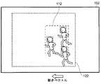
FIG. 15 shows a case where a plurality of constituent subjects are moving in the same direction (for example, during a student race). Further, the
第1〜第n構成被写体検出部611〜61nは、主要被写体検出用情報である入力画像に対して顔検出を行うことで、主要被写体の検出を行うとともに、それぞれの構成被写体について動きベクトルの算出を行う。また、統計処理部61xが、この検出結果である第1〜第n構成被写体位置情報に基づいて主要被写体位置112を算出するとともに、主要被写体の動きベクトルを算出する。そして、切り出し領域決定部62が、主要被写体位置112と主要被写体の動きベクトルとに基づいて切り出し領域122を決定する。 The first to n-th constituent
本具体例では、主要被写体の動きベクトルが特定の方向(図中黒塗りの矢印、左方向)として算出される。そこで、切り出し領域決定部62は、主要被写体位置112が主要被写体の動きベクトルの方向(図中左方向)とは逆方向(図中右方向)に寄った位置になるように、切り出し領域122を決定する。このとき、全ての構成被写体が含まれるように、切り出し領域122を決定しても構わない。 In this specific example, the motion vector of the main subject is calculated as a specific direction (black arrow in the figure, left direction). Accordingly, the cutout
このように構成すると、具体例1及び2と同様に、容易かつ自動的に主要被写体(複数の構成被写体)の状態に応じた構図となる切り出し領域122を決定することが可能となる。特に、構成被写体がどこに向かってどのように移動しているかを明確化することが可能となる。 With this configuration, it is possible to easily and automatically determine the
なお、本具体例において、第1〜第n構成被写体検出部611〜61nが、上述の第1実施例の主要被写体検出部61と同様の検出方法を用いてそれぞれの構成被写体を検出しても構わないし、既存の種々の方法(例えば、ブロックマッチング法や代表点マッチング法など)を利用して動きベクトルを算出することとしても構わない。また、切り出し領域決定部62が、上述の第3実施例の切り出し領域決定部62と同様の決定方法を用いて、切り出し領域を決定しても構わない(図11参照)。 In this specific example, even if the first to nth constituent
また、具体例1に対する具体例2のように、それぞれの構成被写体の動きベクトルがばらつく(相関が所定の大きさ以下となる)場合、切り出し領域決定部62が、それぞれの構成被写体が含まれるように、切り出し領域を決定しても構わない。 Further, as in the specific example 2 with respect to the specific example 1, when the motion vectors of the respective constituent subjects vary (correlation is equal to or smaller than a predetermined magnitude), the cutout
なお、具体例1〜3では、検出された主要被写体の位置と向きとに基づいて切り出し領域を決定する場合(上述の切り出し領域の第3実施例参照)について述べたが、ユーザの操作により入力される構図情報と主要被写体の位置とに基づいて切り出し領域が決定される(上述の切り出し領域の第1及び第2実施例参照)としても構わない。 In specific examples 1 to 3, the case where the cutout area is determined based on the detected position and orientation of the main subject (see the third embodiment of the cutout area described above) has been described. The cutout area may be determined based on the composition information to be performed and the position of the main subject (see the first and second embodiments of the cutout area described above).
また、入力画像内に含まれる複数の被写体の全てを構成被写体としても構わないし、ユーザが選択した被写体を構成被写体としても構わない。また、被写体の画像特徴や動きなどの相関性を利用するなどして自動的に選択された被写体を構成被写体としても構わない。 Further, all of the plurality of subjects included in the input image may be set as the constituent subjects, or the subject selected by the user may be set as the constituent subject. In addition, a subject that is automatically selected by using a correlation such as an image feature or movement of the subject may be used as a constituent subject.
<<他の電子機器への適用>>
上述の例は、撮像装置1の撮像部で得られた入力画像に対して切り出し処理を行い、切り出し画像を記録する場合(即ち、撮像時に切り出し処理を行う場合)のものである。しかしながら、本発明は、外部メモリ10などに記録された入力画像を読み出す際に切り出し処理を行う場合(即ち、再生時に切り出し処理を行う場合)にも、適用することができる。<< Application to other electronic devices >>
The above-described example is a case where a cut-out process is performed on an input image obtained by the image pickup unit of the
図16に、再生時に切り出し処理を行うことが可能な撮像装置1aを示す。図16は、本発明の別の実施形態における撮像装置の基本構成について示すブロック図であり、図1に相当するものである。なお、図1と同様の部分については同じ符号を付し、その詳細な説明については省略する。 FIG. 16 shows an
図16に示す撮像装置1aは、画像処理部6の代わりに画像処理部6aを備える点と、伸長処理部11から入力される画像信号を処理して画像出力回路部12に出力する画像処理部6bをさらに備える点と、を除き、図1の撮像装置1と同様の構成となる。 An
画像処理部6aは、切り出し処理部60を備えない構成となる点を除き、図1に示す画像処理部6と同様の構成となる。一方、画像処理部6bに切り出し処理部60aが備えられる。なお、切り出し処理部60aは、図2や図12に示す切り出し処理部60,60bと同様の構成とすることができる。また、切り出し処理部60aに備えられる主要被写体検出部61として、例えば、上述の第1〜第5実施例の主要被写体検出部61を用いることができる。また、切り出し領域決定部62として、例えば、上述の第1〜第3実施例の切り出し領域決定部62を用いることができる。 The image processing unit 6a has the same configuration as the
また、画像処理部6bに備えられる切り出し処理部60aは、必要に応じて撮像装置1aの各部(例えば、伸長処理部11など)から種々の情報(例えば、音声信号や圧縮処理時の符号化情報)を取得可能であることとする。ただし、図16においては、これらの情報が切り出し処理部60aに入力されることを示す矢印の図示を省略する。 In addition, the cutout processing unit 60a provided in the
図16に示す撮像装置1aは、外部メモリ10に記録されている圧縮符号化信号が伸長処理部11に読み出されるとともに、伸長処理部11で復号されて画像信号が出力される。この画像信号が、画像処理部6bと切り出し処理部60aとに入力されることにより、種々の画像処理や切り出し処理が行われる。なお、切り出し処理部60aの構成及び動作については、図2に示す切り出し処理部60と同様のものとなる。そして、画像処理や切り出し処理が施された画像信号は画像出力回路部12に入力されるとともに、表示装置やスピーカにおいて再生可能な形式に変換されて出力される。 In the
本例のように、再生時に切り出し処理を行う場合では、入力画像が記録されたものであるため、入力画像の取得を停止させることが可能である。そのため、静止させた入力画像に対して切り出し領域を決定することが可能となる。したがって、切り出し領域決定部62の第1及び第2実施例などにおいて、ユーザが切り出し領域の決定を行う場合に、所望の切り出し領域を正確に選択して決定することが可能となる。 As in this example, when the cutout process is performed at the time of reproduction, since the input image is recorded, the acquisition of the input image can be stopped. Therefore, it is possible to determine the cutout region for the input image that is stationary. Therefore, in the first and second examples of the cutout
なお、撮像装置1aが、イメージセンサ2、レンズ部3、AFE4、集音部5、画像処理部6、音声処理部7及び圧縮処理部8を備えない構成としても構わない。即ち、再生機能のみを備える再生専用の装置としても構わない。また、画像処理部6bから出力される画像信号を、再度外部メモリ10に記録可能な構成としても構わない。即ち、編集時に切り出し処理を行うことが可能であるものとしても構わない。 The
また、上述した切り出し処理は、例えば、動画の撮像時や再生時、静止画の撮像時に利用可能である。静止画の撮像時に利用する場合とは、例えば、複数の画像に基づいて1つの静止画の画像を作成する場合などである。 In addition, the clipping process described above can be used, for example, when capturing or reproducing a moving image, or when capturing a still image. The case where the image is used when capturing a still image is, for example, a case where an image of one still image is created based on a plurality of images.
<<その他変形例>>
また、本発明の実施形態における撮像装置1,1aについて、画像処理部6,6a,6bや切り出し処理部60,60a,60bなどのそれぞれの動作を、マイコンなどの制御装置が行うこととしても構わない。さらに、このような制御装置によって実現される機能の全部または一部をプログラムとして記述し、該プログラムをプログラム実行装置(例えばコンピュータ)上で実行することによって、その機能の全部または一部を実現するようにしても構わない。<< Other variations >>
In the
また、上述した場合に限らず、図1の撮像装置1、図2の切り出し処理部60、図12の切り出し処理部60b及び図16の撮像装置1a、切り出し処理部60aは、ハードウェア、或いは、ハードウェアとソフトウェアの組み合わせによって実現可能である。また、ソフトウェアを用いて撮像装置1,1aや切り出し処理部60,60a,60bを構成する場合、ソフトウェアによって実現される部位についてのブロック図は、その部位の機能ブロック図を表すこととする。 The
以上、本発明の実施形態についてそれぞれ説明したが、本発明の範囲はこれに限定されるものではなく、発明の主旨を逸脱しない範囲で種々の変更を加えて実行することができる。 As mentioned above, although each embodiment of the present invention was described, the scope of the present invention is not limited to this, and can be executed with various modifications without departing from the gist of the invention.
本発明は、入力画像を切り出して所望の切り出し画像を得る画像処理装置に関する。また、デジタルビデオカメラに代表される撮像装置などの電子機器に関する。 The present invention relates to an image processing apparatus that cuts out an input image and obtains a desired cut-out image. The present invention also relates to an electronic device such as an imaging device represented by a digital video camera.
1 撮像装置
2 イメージサンサ
3 レンズ部
4 AFE
5 集音部
6 画像処理部
60,60a,60b 切り出し処理部
61,61b 主要被写体検出部
611〜61n 構成被写体検出部
61x 統計処理部
62 切り出し領域決定部
63 切り出し部
7 音声処理部
8 圧縮処理部
9 ドライバ部
10 外部メモリ
11 伸長処理部
12 画像出力回路部
13 音声出力回路部
14 CPU
15 メモリ
16 操作部
17 TG部
18 バス
19 バスDESCRIPTION OF
DESCRIPTION OF
15
Claims (9)
Translated fromJapanese前記切り出し処理部が、
前記入力画像中の主要被写体の位置を検出する主要被写体検出部と、
前記主要被写体検出部によって検出される前記主要被写体の位置を含む切り出し領域を決定する切り出し領域決定部と、
前記入力画像から前記切り出し領域を切り出して前記切り出し画像を生成する切り出し部と、を備え、
前記主要被写体検出部によって検出される前記主要被写体の位置が、前記切り出し領域中の所定の位置となるように、前記切り出し領域決定部が前記切り出し領域を決定することを特徴とする画像処理装置。In an image processing apparatus including a cutout processing unit that cuts out a predetermined area from an input image and generates a cutout image,
The cutout processing unit
A main subject detection unit for detecting the position of the main subject in the input image;
A cutout region determination unit that determines a cutout region that includes the position of the main subject detected by the main subject detection unit;
A cutout unit that cuts out the cutout region from the input image and generates the cutout image,
The image processing apparatus, wherein the cutout region determination unit determines the cutout region so that a position of the main subject detected by the main subject detection unit is a predetermined position in the cutout region.
前記構図情報にしたがって、前記切り出し領域決定部が前記切り出し領域を決定することを特徴とする請求項1に記載の画像処理装置。Composition information specifying the relationship between the position of the main subject detected by the main subject detection unit and the position of the cutout region is input to the cutout region determination unit,
The image processing apparatus according to claim 1, wherein the cutout region determination unit determines the cutout region according to the composition information.
前記切り出し領域決定部が、前記主要被写体検出部によって検出される前記主要被写体の向きに基づいて、前記切り出し領域を決定することを特徴とする請求項1に記載の画像処理装置。The main subject detection unit detects the orientation of the main subject,
The image processing apparatus according to claim 1, wherein the cutout region determination unit determines the cutout region based on an orientation of the main subject detected by the main subject detection unit.
前記主要被写体検出部が、前記入力画像中の前記構成被写体のそれぞれの位置を検出し、当該それぞれの位置に基づいて前記主要被写体の位置を検出することを特徴とする請求項1〜請求項5のいずれかに記載の画像処理装置。When the main subject is composed of a plurality of constituent subjects,
6. The main subject detection unit detects a position of each of the constituent subjects in the input image, and detects the position of the main subject based on the respective positions. An image processing apparatus according to any one of the above.
前記切り出し領域決定部が、前記主要被写体検出部によって検出される前記主要被写体の向きに基づいて、前記切り出し領域を決定することを特徴とする請求項6に記載の画像処理装置。The main subject detection unit detects the orientation of each of the constituent subjects, and detects the orientation of the main subject based on the respective orientations.
The image processing apparatus according to claim 6, wherein the cutout region determination unit determines the cutout region based on an orientation of the main subject detected by the main subject detection unit.
前記構成被写体のそれぞれの向きの相関が所定の大きさ以下であるとき、
前記切り出し領域決定部は、前記複数の構成被写体のそれぞれが含まれる前記切り出し領域を決定することを特徴とする請求項6または請求項7に記載の画像処理装置。The main subject detection unit detects the orientation of each of the constituent subjects, and detects the orientation of the main subject based on the respective orientations.
When the correlation between the orientations of the constituent subjects is a predetermined magnitude or less,
The image processing apparatus according to claim 6, wherein the cutout region determination unit determines the cutout region including each of the plurality of constituent subjects.
当該画像処理装置から出力される前記切り出し画像を記録または再生することを特徴とする電子機器。The image processing apparatus according to any one of claims 1 to 8,
An electronic apparatus that records or reproduces the cut-out image output from the image processing apparatus.
Priority Applications (3)
| Application Number | Priority Date | Filing Date | Title |
|---|---|---|---|
| JP2009172838AJP2010103972A (en) | 2008-09-25 | 2009-07-24 | Image processing device and electronic appliance |
| CN2009101731963ACN101931747A (en) | 2008-09-25 | 2009-09-14 | Image processing device and electronic equipment |
| US12/567,190US20100074557A1 (en) | 2008-09-25 | 2009-09-25 | Image Processing Device And Electronic Appliance |
Applications Claiming Priority (2)
| Application Number | Priority Date | Filing Date | Title |
|---|---|---|---|
| JP2008245849 | 2008-09-25 | ||
| JP2009172838AJP2010103972A (en) | 2008-09-25 | 2009-07-24 | Image processing device and electronic appliance |
Publications (1)
| Publication Number | Publication Date |
|---|---|
| JP2010103972Atrue JP2010103972A (en) | 2010-05-06 |
Family
ID=42294153
Family Applications (1)
| Application Number | Title | Priority Date | Filing Date |
|---|---|---|---|
| JP2009172838APendingJP2010103972A (en) | 2008-09-25 | 2009-07-24 | Image processing device and electronic appliance |
Country Status (2)
| Country | Link |
|---|---|
| JP (1) | JP2010103972A (en) |
| CN (1) | CN101931747A (en) |
Cited By (9)
| Publication number | Priority date | Publication date | Assignee | Title |
|---|---|---|---|---|
| JP2012205053A (en)* | 2011-03-25 | 2012-10-22 | Toshiba Corp | Image processing apparatus, image coding system, and image decoding system |
| WO2013111415A1 (en) | 2012-01-26 | 2013-08-01 | ソニー株式会社 | Image processing apparatus and image processing method |
| JP2014209707A (en)* | 2013-03-25 | 2014-11-06 | パナソニック株式会社 | Device and method for video reproduction |
| WO2015072166A1 (en)* | 2013-11-18 | 2015-05-21 | オリンパスイメージング株式会社 | Imaging device, imaging assistant method, and recoding medium on which imaging assistant program is recorded |
| WO2016167017A1 (en)* | 2015-04-14 | 2016-10-20 | ソニー株式会社 | Image processing device, image processing method, and image processing system |
| US9848133B2 (en) | 2013-03-26 | 2017-12-19 | Panasonic Intellectual Property Management Co., Ltd. | Image generation device, imaging device, image generation method, and program for generating a new image from a captured image |
| JP2019022166A (en)* | 2017-07-20 | 2019-02-07 | 京セラドキュメントソリューションズ株式会社 | Image processing apparatus, image processing method, and image processing program |
| JP2020123894A (en)* | 2019-01-31 | 2020-08-13 | オリンパス株式会社 | Imaging device, imaging method, and imaging program |
| WO2021038752A1 (en)* | 2019-08-28 | 2021-03-04 | 株式会社ソニー・インタラクティブエンタテインメント | Image processing device, system, image processing method and image processing program |
Families Citing this family (3)
| Publication number | Priority date | Publication date | Assignee | Title |
|---|---|---|---|---|
| JP5987306B2 (en)* | 2011-12-06 | 2016-09-07 | ソニー株式会社 | Image processing apparatus, image processing method, and program |
| CN104378545A (en)* | 2013-08-16 | 2015-02-25 | 中兴通讯股份有限公司 | Photographing processing method and system |
| JP6518409B2 (en)* | 2014-06-30 | 2019-05-22 | オリンパス株式会社 | Imaging apparatus and imaging method |
Citations (5)
| Publication number | Priority date | Publication date | Assignee | Title |
|---|---|---|---|---|
| JP2001094919A (en)* | 1999-09-20 | 2001-04-06 | Canon Inc | Image recording apparatus, method, and computer-readable storage medium |
| JP2003189273A (en)* | 2001-12-20 | 2003-07-04 | Sharp Corp | Speaker identification device and video conference system provided with the speaker identification device |
| JP2007006165A (en)* | 2005-06-24 | 2007-01-11 | Fujifilm Holdings Corp | Imaging device, imaging method, and imaging program |
| JP2008042800A (en)* | 2006-08-10 | 2008-02-21 | Fujifilm Corp | Trimming apparatus and method, and program |
| JP2008219696A (en)* | 2007-03-07 | 2008-09-18 | Casio Comput Co Ltd | Camera device, camera device control program, and camera device control method |
Family Cites Families (3)
| Publication number | Priority date | Publication date | Assignee | Title |
|---|---|---|---|---|
| CN101123692B (en)* | 2002-10-25 | 2012-09-26 | 索尼计算机娱乐公司 | Method and apparatus for generating new images by using image data that vary along time axis |
| JP2006279568A (en)* | 2005-03-29 | 2006-10-12 | Fujitsu Ltd | Imaging device |
| CN101051385B (en)* | 2006-04-07 | 2011-11-23 | 欧姆龙株式会社 | Specific subject tracking method and device, and feature part tracking method and device |
- 2009
- 2009-07-24JPJP2009172838Apatent/JP2010103972A/enactivePending
- 2009-09-14CNCN2009101731963Apatent/CN101931747A/enactivePending
Patent Citations (5)
| Publication number | Priority date | Publication date | Assignee | Title |
|---|---|---|---|---|
| JP2001094919A (en)* | 1999-09-20 | 2001-04-06 | Canon Inc | Image recording apparatus, method, and computer-readable storage medium |
| JP2003189273A (en)* | 2001-12-20 | 2003-07-04 | Sharp Corp | Speaker identification device and video conference system provided with the speaker identification device |
| JP2007006165A (en)* | 2005-06-24 | 2007-01-11 | Fujifilm Holdings Corp | Imaging device, imaging method, and imaging program |
| JP2008042800A (en)* | 2006-08-10 | 2008-02-21 | Fujifilm Corp | Trimming apparatus and method, and program |
| JP2008219696A (en)* | 2007-03-07 | 2008-09-18 | Casio Comput Co Ltd | Camera device, camera device control program, and camera device control method |
Cited By (18)
| Publication number | Priority date | Publication date | Assignee | Title |
|---|---|---|---|---|
| JP2012205053A (en)* | 2011-03-25 | 2012-10-22 | Toshiba Corp | Image processing apparatus, image coding system, and image decoding system |
| WO2013111415A1 (en) | 2012-01-26 | 2013-08-01 | ソニー株式会社 | Image processing apparatus and image processing method |
| US9826170B2 (en) | 2012-01-26 | 2017-11-21 | Sony Corporation | Image processing of captured three-dimensional images |
| JP2014209707A (en)* | 2013-03-25 | 2014-11-06 | パナソニック株式会社 | Device and method for video reproduction |
| US9848133B2 (en) | 2013-03-26 | 2017-12-19 | Panasonic Intellectual Property Management Co., Ltd. | Image generation device, imaging device, image generation method, and program for generating a new image from a captured image |
| WO2015072166A1 (en)* | 2013-11-18 | 2015-05-21 | オリンパスイメージング株式会社 | Imaging device, imaging assistant method, and recoding medium on which imaging assistant program is recorded |
| JPWO2015072166A1 (en)* | 2013-11-18 | 2017-03-16 | オリンパス株式会社 | IMAGING DEVICE, IMAGING ASSIST METHOD, AND RECORDING MEDIUM CONTAINING IMAGING ASSIST PROGRAM |
| US9628700B2 (en) | 2013-11-18 | 2017-04-18 | Olympus Corporation | Imaging apparatus, imaging assist method, and non-transitory recoding medium storing an imaging assist program |
| WO2016167017A1 (en)* | 2015-04-14 | 2016-10-20 | ソニー株式会社 | Image processing device, image processing method, and image processing system |
| JPWO2016167017A1 (en)* | 2015-04-14 | 2018-02-08 | ソニー株式会社 | Image processing apparatus, image processing method, and image processing system |
| US11263769B2 (en) | 2015-04-14 | 2022-03-01 | Sony Corporation | Image processing device, image processing method, and image processing system |
| JP2019022166A (en)* | 2017-07-20 | 2019-02-07 | 京セラドキュメントソリューションズ株式会社 | Image processing apparatus, image processing method, and image processing program |
| JP2020123894A (en)* | 2019-01-31 | 2020-08-13 | オリンパス株式会社 | Imaging device, imaging method, and imaging program |
| JP7236869B2 (en) | 2019-01-31 | 2023-03-10 | オリンパス株式会社 | IMAGING DEVICE, IMAGING METHOD AND IMAGING PROGRAM |
| WO2021038752A1 (en)* | 2019-08-28 | 2021-03-04 | 株式会社ソニー・インタラクティブエンタテインメント | Image processing device, system, image processing method and image processing program |
| JPWO2021038752A1 (en)* | 2019-08-28 | 2021-03-04 | ||
| JP7304955B2 (en) | 2019-08-28 | 2023-07-07 | 株式会社ソニー・インタラクティブエンタテインメント | Image processing device, system, image processing method and image processing program |
| US12111409B2 (en) | 2019-08-28 | 2024-10-08 | Sony Interactive Entertainment Inc. | Image processing apparatus, system, image processing method, and image processing program |
Also Published As
| Publication number | Publication date |
|---|---|
| CN101931747A (en) | 2010-12-29 |
Similar Documents
| Publication | Publication Date | Title |
|---|---|---|
| JP2010103972A (en) | Image processing device and electronic appliance | |
| US8421887B2 (en) | Image sensing apparatus | |
| JP5084696B2 (en) | Image processing apparatus, image processing method, and electronic apparatus | |
| US8401364B2 (en) | Imaging device and playback device | |
| KR101737081B1 (en) | Digital photographing apparatus, method of controlling thereof and recording medium | |
| JP5202283B2 (en) | Imaging apparatus and electronic apparatus | |
| JP5202211B2 (en) | Image processing apparatus and electronic apparatus | |
| JP5183297B2 (en) | Image processing apparatus, imaging apparatus, and image processing method | |
| US20100074557A1 (en) | Image Processing Device And Electronic Appliance | |
| US20110193986A1 (en) | Image sensing device | |
| KR101710626B1 (en) | Digital photographing apparatus and control method thereof | |
| US20110128415A1 (en) | Image processing device and image-shooting device | |
| JP2009065587A (en) | Voice-recording device and voice-reproducing device | |
| JP2009124644A (en) | Image processing device, imaging device, and image reproduction device | |
| JP2010028608A (en) | Image processor, image sensing device, reproducer and method for processing image | |
| JP5173915B2 (en) | Image processing apparatus and imaging apparatus | |
| JP2011155582A (en) | Imaging device | |
| JP2008172395A (en) | Imaging apparatus and image processing apparatus, method, and program | |
| US20120060614A1 (en) | Image sensing device | |
| JP2011109693A (en) | Imaging device | |
| JP2011119934A (en) | Image shooting device and image shooting method | |
| JP5272206B2 (en) | Image processing apparatus, image processing method, and imaging apparatus | |
| JP5072714B2 (en) | Audio recording apparatus and audio reproduction apparatus | |
| JP2009021893A (en) | Imaging device and method | |
| JP5325330B2 (en) | Image processing apparatus and imaging apparatus |
Legal Events
| Date | Code | Title | Description |
|---|---|---|---|
| A621 | Written request for application examination | Free format text:JAPANESE INTERMEDIATE CODE: A621 Effective date:20120712 | |
| A711 | Notification of change in applicant | Free format text:JAPANESE INTERMEDIATE CODE: A711 Effective date:20130404 | |
| RD03 | Notification of appointment of power of attorney | Free format text:JAPANESE INTERMEDIATE CODE: A7423 Effective date:20130606 | |
| A977 | Report on retrieval | Free format text:JAPANESE INTERMEDIATE CODE: A971007 Effective date:20130611 | |
| A131 | Notification of reasons for refusal | Free format text:JAPANESE INTERMEDIATE CODE: A131 Effective date:20130619 | |
| A521 | Request for written amendment filed | Free format text:JAPANESE INTERMEDIATE CODE: A523 Effective date:20130808 | |
| A02 | Decision of refusal | Free format text:JAPANESE INTERMEDIATE CODE: A02 Effective date:20140121 | |
| A521 | Request for written amendment filed | Free format text:JAPANESE INTERMEDIATE CODE: A523 Effective date:20140421 | |
| A911 | Transfer to examiner for re-examination before appeal (zenchi) | Free format text:JAPANESE INTERMEDIATE CODE: A911 Effective date:20140430 | |
| A912 | Re-examination (zenchi) completed and case transferred to appeal board | Free format text:JAPANESE INTERMEDIATE CODE: A912 Effective date:20140620 |