JP2010103746A - Imaging apparatus - Google Patents
Imaging apparatusDownload PDFInfo
- Publication number
- JP2010103746A JP2010103746AJP2008273061AJP2008273061AJP2010103746AJP 2010103746 AJP2010103746 AJP 2010103746AJP 2008273061 AJP2008273061 AJP 2008273061AJP 2008273061 AJP2008273061 AJP 2008273061AJP 2010103746 AJP2010103746 AJP 2010103746A
- Authority
- JP
- Japan
- Prior art keywords
- flicker
- image
- light
- brightness
- receiving element
- Prior art date
- Legal status (The legal status is an assumption and is not a legal conclusion. Google has not performed a legal analysis and makes no representation as to the accuracy of the status listed.)
- Pending
Links
- 238000003384imaging methodMethods0.000titleclaimsabstractdescription29
- 238000005096rolling processMethods0.000claimsabstractdescription10
- 230000000737periodic effectEffects0.000claimsdescription3
- 230000006866deteriorationEffects0.000abstract1
- 238000005259measurementMethods0.000description10
- 238000005375photometryMethods0.000description9
- 238000000034methodMethods0.000description6
- 238000010586diagramMethods0.000description5
- 230000015556catabolic processEffects0.000description1
- 238000006731degradation reactionMethods0.000description1
- 230000003287optical effectEffects0.000description1
Images


Landscapes
- Transforming Light Signals Into Electric Signals (AREA)
Abstract
Description
Translated fromJapanese本発明は、撮像装置に関し、特にフリッカによるAF精度低下を抑制する撮像装置に関する。 The present invention relates to an imaging apparatus, and more particularly, to an imaging apparatus that suppresses AF accuracy degradation caused by flicker.
蛍光灯の下のように、明るさが周期的に変動するフリッカがある環境下で、デジタルカメラで短い露光時間で撮像を行うと、フレーム間で画像の輝度値が変動する。また、撮像素子がCMOSのようにローリングシャッタで駆動される場合には、画像上にラインごとの光の強弱を示す縞模様が発生する。AFを行う画像が暗い場合、またはAF領域と該縞模様の暗い部分とが重複した場合には、AF精度が低下する。 When an image is captured with a short exposure time with a digital camera in an environment where there is flicker whose brightness varies periodically, such as under a fluorescent lamp, the luminance value of the image varies between frames. Further, when the image sensor is driven by a rolling shutter like a CMOS, a stripe pattern indicating the intensity of light for each line is generated on the image. If the image to be AF is dark, or if the AF area and the dark part of the striped pattern overlap, the AF accuracy is lowered.
特許文献1では、フリッカを検出した場合には、露光時間を長くしてフリッカの発生を抑える撮像装置を開示する。
しかし、露光時間を長くする必要があるため、動きの早い被写体を撮像する場合など、撮像に適さない場合もある。 However, since it is necessary to lengthen the exposure time, it may not be suitable for imaging, such as when imaging a fast-moving subject.
したがって本発明の目的は、露光時間を変えずに、フリッカによるAF精度低下を抑制する撮像装置を提供することである。 Accordingly, an object of the present invention is to provide an imaging apparatus that suppresses a reduction in AF accuracy due to flicker without changing the exposure time.
本発明に係る撮像装置は、被写体の明るさを検出する受光素子と、受光素子で得られた明るさに関する情報に基づいて、明るさの周期的な変動であるフリッカの発生有無の判断、及びフリッカの周期の算出を行い、露光時間がフリッカの周期よりも短い場合に、撮像素子のフレームレートをフリッカの周期の整数倍に調整する制御部とを備える。 An image pickup apparatus according to the present invention includes a light receiving element that detects the brightness of a subject, determination of whether or not flicker that is a periodic variation in brightness is generated based on information about the brightness obtained by the light receiving element, and A controller that calculates a flicker period and adjusts the frame rate of the image sensor to an integral multiple of the flicker period when the exposure time is shorter than the flicker period;
本実施形態では、フレームレートをフリッカの周期の整数倍に合わせることにより、フリッカによるフレームごとの画像の輝度値のばらつきを抑えることが可能になる。輝度値のばらつきを抑えることにより、安定的なAF精度を確保することが可能になる。 In this embodiment, by adjusting the frame rate to an integral multiple of the flicker cycle, it is possible to suppress variations in the luminance value of the image for each frame due to flicker. Stable AF accuracy can be ensured by suppressing variations in luminance values.
好ましくは、撮像素子は、ローリングシャッタで駆動し、制御部は、フリッカを発生させる光の強さが最大値を示すタイミングで、AF領域を含むラインの露光が行われるように、垂直同期信号の出力タイミングを調整する。 Preferably, the imaging device is driven by a rolling shutter, and the control unit is configured to output the vertical synchronization signal so that the line including the AF area is exposed at a timing at which the intensity of light that generates flicker has a maximum value. Adjust the output timing.
CMOSなどローリングシャッタで駆動する撮像素子の場合には、フリッカにより、画像にラインごとの光の強弱を示す縞模様が発生するが、垂直同期信号の出力タイミングを調整することにより、AF領域と、フリッカによる縞模様の暗い部分との重複を少なくすることが可能になり、かかる制御を行わない場合に比べて、AF精度を向上させることが可能になる。 In the case of an image sensor driven by a rolling shutter such as a CMOS, a flicker causes a stripe pattern indicating the intensity of light for each line due to flicker, but by adjusting the output timing of the vertical synchronization signal, It is possible to reduce the overlap of the dark portion of the stripe pattern due to flicker, and it is possible to improve the AF accuracy as compared with the case where such control is not performed.
また、好ましくは、受光素子は、撮像素子のフレームレートや、フリッカの周期よりも短い時間ごとに、明るさの検出を行う。 Preferably, the light receiving element detects the brightness every time shorter than the frame rate of the image sensor and the flicker cycle.
明るさの検出を短い時間の間隔で行うことにより、早くフリッカの周期の算出などを行うことが可能になる。 By detecting the brightness at short time intervals, it is possible to quickly calculate the flicker cycle.
以上のように本発明によれば、露光時間を変えずに、フリッカによるAF精度低下を抑制する撮像装置を提供することができる。 As described above, according to the present invention, it is possible to provide an imaging apparatus that suppresses a decrease in AF accuracy due to flicker without changing the exposure time.
以下、本実施形態について、図を用いて説明する。撮像装置1は、デジタルカメラである。撮像装置1の撮像に関する部分は、撮像装置1の電源のオンオフ状態の切り替えのために使用される電源ボタン9、レリーズボタン13、各部の制御を行う制御部30、レンズ駆動部45、露出制御部47、受光素子49、レンズ51、CMOSなど走査ラインごとに順次露光が行われるローリングシャッタで駆動される撮像素子53、AFE(アナログフロントエンド)55、DSP(映像信号処理回路)60、記録部70、及び表示部90を備える(図1参照)。 Hereinafter, the present embodiment will be described with reference to the drawings. The
被写体像は、レンズ51を介した光学像として、撮像素子53で撮像される。撮像により得られた画像データは、AFE55でアナログ信号からデジタル信号に変換され、DSP60でホワイトバランス処理を含む画像処理が施される。かかる動作が第1時間t1ごとに行われ、表示部90に、画像データに基づいてスルー画像が表示される(ライブビュー表示)。第1時間t1は、通常時には1/30秒に設定されるが、フリッカ(周期的な明るさ変動)検出時には、フリッカ周期FTの整数倍に設定される。また、フリッカ検出時で且つ露光時間e1がフリッカ周期FTよりも短い場合には、第1時間t1の開始タイミングの調整も行われる。 The subject image is captured by the
レリーズボタン13は、半押しすることにより測光スイッチ(不図示)がオン状態にされ測光やレンズ駆動部45による測距及び合焦動作が行われる。測光は、撮像素子53における撮像で得られた画像データに基づいて行われる。具体的には、DSP60は、画像処理において生成される輝度信号から測光領域における輝度値(被写体の明るさに関する情報)を求め、これを測光結果として、制御部30に出力する。制御部30は、輝度値に基づいて適正な露出(絞りや露光時間e1)を算出する(露出演算)。測距は、撮像で得られた画像データから、AF領域に対応する部分の画像のコントラストに基づいて行われる。 When the
本実施形態では、レリーズボタン13の半押し後に、測光や測距を開始する形態で説明したが、電源ボタン9を使って撮像装置1の電源がオン状態にされた後、常時測光や測距を行う形態であってもよい。この場合、レリーズボタン13が半押しされると、測光や測距動作が停止され、半押しされる直前の測光や測距結果が、レリーズボタン13の全押しに対応する撮影に使用される。また、撮像装置1の電源がオン状態にされた後から、フリッカ周期FTに対応する第1時間t1の調整が可能になる。 In the present embodiment, the description has been given of the case where the photometry and the distance measurement are started after the
レリーズボタン13は、全押しすることによりレリーズスイッチ(不図示)がオン状態にされ、制御部30で算出された露出で撮像が行われるように、露出制御部47により絞りや露光時間e1が制御された状態で、撮像が行われる。撮像により得られた画像データに対応する画像は、DSP60における画像処理後に、表示部90に表示され、画像データは記録部70に記録される。 When the
受光素子49は、レンズ51を介した光を第2時間t2ごとに受光して、かかる光の明るさに関する情報を制御部30に出力する。具体的には、受光素子49として、測光に用いられる受光素子が考えられる。第2時間t2は、第1時間t1やフリッカ周期FTよりも短い値に設定される。制御部30は、第2時間t2ごとの受光素子49から出力される情報に基づいて、フリッカ発生有無の判断、明るさの最小値と最大値、及びフリッカの周期の算出を行う。フリッカは、光の強弱の繰り返しであり、例えば、50Hzの周波数で点灯している蛍光灯の下で撮像した場合には、フリッカ周期FTが1/100秒のフリッカが発生する。なお、フリッカ発生の有無などを検出する目的であるため、受光素子49は、被写体の明るさを検出するものであれば、レンズ51を介さない光を受光する形態であってもよい。 The
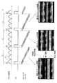
露光時間e1がフリッカ周期FTよりも短い場合には、撮像素子53のラインごとの露光量の差異により、フレームごとに画像の輝度値の差異(フレーム間の出力変動)が生じ、また画像にラインごとの光の強弱を示す縞模様が発生する(図2参照)。 When the exposure time e1 is shorter than the flicker cycle FT, a difference in image luminance value (output fluctuation between frames) is generated for each frame due to a difference in exposure amount for each line of the
図2の下段に示す1番目のフレーム画像、2番目のフレーム画像、3番目のフレーム画像は、フリッカを発生させる光が強い時に露光されたラインに対応した明るい領域(波線部分)、フリッカを発生させる光が中程度の時に露光されたラインに対応した中程度の明るさの領域(網掛け部分)、フリッカを発生させる光が弱い時に露光されたラインに対応し暗い領域(黒塗り部分)を含む縞模様であって、それぞれの縞模様のパターンが異なる状態を示す。 The first frame image, the second frame image, and the third frame image shown in the lower part of FIG. 2 generate a bright area (dashed line portion) and flicker corresponding to the exposed line when the light that generates flicker is strong. A moderately bright area (shaded area) corresponding to an exposed line when the light to be generated is medium, and a dark area (black area) corresponding to an exposed line when the light that generates flicker is weak The striped pattern includes different striped patterns.
また、撮像素子53のフレーム周期である第1時間t1とフリッカ周期FTの整数倍が一致していない場合には、フレームごとに発生する縞模様が変化し、フレームごとの画像の輝度値が変動する。図2の下段は、1番目のフレームで得られた画像、2番目のフレームで得られた画像、及び3番目のフレームで得られた画像における、フリッカによって発生する縞模様が変化する状態を示す。 In addition, when the first time t1, which is the frame period of the
制御部30は、フリッカが発生していると判断し、且つ露光時間e1がフリッカ周期FTよりも短い場合には、第1時間t1をフリッカ周期FTの整数倍に合わせるようにフレームレートを調整する、すなわち垂直同期信号VDの出力タイミングを調整する(図3参照)。なお、フリッカが発生している場合であっても、露光時間がフリッカ周期FT以上である場合には、画像が全体的に明るくなり、すなわち縞模様の暗い領域も明るい領域も明るくなり、該縞模様が見えにくくなるため、フレームレートは通常時の値に設定される、すなわちフレームレートを調整する必要はない。なお、露光時間がフリッカ周期FTの整数倍である場合には、該縞模様は発生しない。 The
図3の下段に示す1番目のフレーム画像、2番目のフレーム画像、3番目のフレーム画像は、フリッカを発生させる光が強い時に露光されたラインに対応した明るい領域(波線部分)、フリッカを発生させる光が中程度の時に露光されたラインに対応した中程度の明るさの領域(網掛け部分)、フリッカを発生させる光が弱い時に露光されたラインに対応し暗い領域(黒塗り部分)を含む縞模様であって、それぞれの縞模様のパターンが同じ状態を示す。 The first frame image, the second frame image, and the third frame image shown in the lower part of FIG. 3 generate a bright area (dashed line portion) and flicker corresponding to the exposed line when the light that generates flicker is strong. A moderately bright area (shaded area) corresponding to an exposed line when the light to be generated is medium, and a dark area (black area) corresponding to an exposed line when the light that generates flicker is weak It is a striped pattern which contains, Comprising: Each striped pattern shows the same state.
さらに、撮像素子53上の測距を行う領域(AF領域)にフリッカによる縞模様の暗い部分が少なくなるように、すなわちフリッカを発生させる光の強さが最大値を示すタイミングで、AF領域を含むラインの露光が行われるように、第1時間t1の開始タイミング(垂直同期信号VDの出力タイミング)を調整する(図4参照)。 Further, the AF area is adjusted so that the dark area of the stripe pattern due to flicker is reduced in the area (AF area) for distance measurement on the
図4の下段に示す1番目のフレーム画像、2番目のフレーム画像、3番目のフレーム画像は、フリッカを発生させる光が強い時に露光されたラインに対応した明るい領域(波線部分)、フリッカを発生させる光が中程度の時に露光されたラインに対応した中程度の明るさの領域(網掛け部分)、フリッカを発生させる光が弱い時に露光されたラインに対応し暗い領域(黒塗り部分)を含む縞模様であって、それぞれの縞模様のパターンが同じで、画像中央に設けられたAF領域を含むラインがフリッカを発生させる光が強い時に露光されるように調整された状態を示す。但し、AF領域は、画像中央に限られるものではなく、AF領域の変動に応じて、垂直同期信号VDの出力タイミングを調整する必要がある。 The first frame image, the second frame image, and the third frame image shown in the lower part of FIG. 4 generate bright areas (dashed lines) and flicker that correspond to the exposed lines when the light that generates flicker is strong. A moderately bright area (shaded area) corresponding to an exposed line when the light to be generated is medium, and a dark area (black area) corresponding to an exposed line when the light that generates flicker is weak This shows a state in which the stripe pattern is the same and the line including the AF area provided in the center of the image is adjusted to be exposed when the light that generates flicker is strong. However, the AF area is not limited to the center of the image, and it is necessary to adjust the output timing of the vertical synchronization signal VD according to the fluctuation of the AF area.
次に、測距動作手順について、図5のフローチャートを用いて説明する。レリーズボタン13が半押しされると、ステップS11で、制御部30は、受光素子49から出力された光の強さに関する情報に基づいて、光の強さの最大値と最小値を算出し、最大値と最小値を示す時間間隔からフリッカ周期FTを算出し、フリッカが発生しているか否かを判断する。また、並行して測光が行われる。制御部30は、測光結果に基づいて適正な露出(絞りや露光時間e1)を算出する。フリッカが発生している場合には、ステップS12に進められ、発生していない場合には、フレームレートの調整を行わずに、ステップS15に進められる。 Next, the distance measurement operation procedure will be described with reference to the flowchart of FIG. When the
なお、本実施形態では、測光、測距をレリーズボタン13の半押し後に行う形態を説明したが、電源ボタン9を使って撮像装置1の電源がオン状態にされた後、常に行う形態であってもよい。この場合は、第1時間t1ごとにかかる測距動作が行われる。 In the present embodiment, a mode in which photometry and distance measurement are performed after the
ステップS12で、制御部30は、露光時間e1がフリッカ周期FTよりも短いか否かを判断する。短い場合には、ステップS13に進められ、短くない場合には、フレームレートの調整を行わずに、ステップS15に進められる。ステップS13で、制御部30は、フレームレートの調整を行う。具体的には、制御部30は、第1時間t1をフリッカ周期FTの整数倍に設定し、ステップS14で、制御部30は、光の強さの最大値を示すタイミングで、AF領域を含むラインの露光が行われるように、垂直同期信号VDの出力タイミングを調整する。ステップS15で、測距が行われる。 In step S12, the
本実施形態では、垂直同期信号VDの出力間隔を変えて、第1時間t1(フレームレート)を調整することにより、フリッカによるフレームごとの画像の輝度値のばらつきを抑えることが可能になる。また、垂直同期信号VDの出力タイミングを調整することにより、AF領域と、フリッカによる縞模様の暗い部分との重複を少なくすることが可能になり、かかる制御を行わない場合に比べて、AF精度を向上させることが可能になる。 In the present embodiment, by varying the output interval of the vertical synchronization signal VD and adjusting the first time t1 (frame rate), it is possible to suppress variation in the luminance value of the image for each frame due to flicker. Further, by adjusting the output timing of the vertical synchronization signal VD, it becomes possible to reduce the overlap between the AF area and the dark portion of the stripe pattern due to flicker, and compared with the case where such control is not performed. It becomes possible to improve.
なお、本実施形態では、撮像素子53がローリングシャッタで駆動されるCMOSなどである形態を説明したが、CCDなど総ての走査ラインが同時に露光されるグローバルシャッタで駆動される他の撮像素子でもよい。この場合は、フリッカの発生時にフレームレートの調整が行われる。但し、画像に縞模様は発生しないため、フレームごとの画像の輝度値を一定にするだけでいいので、垂直同期信号の出力タイミングのAF領域に応じた調整は行われない。 In this embodiment, the
図6は、フレームレートの調整を行う前の状態を示す。1番目のフレームでは、露光時間e1の間、フリッカを発生させる光が強い状態で、明るい画像(波線表示)が得られ、2番目のフレームでは、露光時間e1の間、フリッカを発生させる光が中程度の状態で、中程度に明るい画像(網掛け表示)が得られ、3番目のフレームでは、露光時間e1の間、フリッカを発生させる光が弱い状態で、暗い画像(黒塗り表示)が得られる。図7は、フレームレートの調整を行った後の状態を示す。いずれのフレームでも、露光時間e1の間、フリッカの光が同程度の状態であり、同じ明るさの画像(網掛け表示)が得られる。 FIG. 6 shows a state before adjusting the frame rate. In the first frame, a bright image (wavy line display) is obtained in a state where the light that generates flicker is strong during the exposure time e1, and in the second frame, the light that generates flicker is generated during the exposure time e1. A moderately bright image (shaded display) is obtained in a medium state, and in the third frame, a dark image (black display) is displayed in a state where light that generates flicker is weak during the exposure time e1. can get. FIG. 7 shows a state after adjusting the frame rate. In any frame, the flicker light is in the same level during the exposure time e1, and an image (shaded display) having the same brightness is obtained.
また、フリッカの発生有無の判断などに使用するために、撮像素子53と別の受光素子49を使う形態を説明したが、撮像素子53を使う形態であってもよい。この場合に、制御部30は、フレームごとの画像の輝度値に基づいて、フリッカの発生有無などを判断する。但し、フレームレート(1/30秒)ごとに得られる複数の画像の輝度値を得る必要があるため、受光素子49を使う形態に比べて処理に時間がかかる。 Further, although the embodiment using the
1 撮像装置
9 電源ボタン
13 レリーズボタン
30 制御部
45 レンズ駆動部
47 露出制御部
49 受光素子
51 レンズ
53 撮像素子
55 AFE
60 DSP
70 記録部
90 表示部DESCRIPTION OF
60 DSP
70
Claims (3)
Translated fromJapanese前記受光素子で得られた明るさに関する情報に基づいて、明るさの周期的な変動であるフリッカの発生有無の判断、及び前記フリッカの周期の算出を行い、露光時間が前記フリッカの周期よりも短い場合に、撮像素子のフレームレートを前記フリッカの周期の整数倍に調整する制御部とを備えることを特徴とする撮像装置。A light receiving element for detecting the brightness of the subject;
Based on the information on the brightness obtained by the light receiving element, it is determined whether or not flicker, which is a periodic fluctuation of brightness, and the flicker period is calculated, and the exposure time is shorter than the flicker period. An image pickup apparatus comprising: a control unit that adjusts a frame rate of the image pickup element to an integral multiple of the flicker period when the image pickup element is short.
前記制御部は、前記フリッカを発生させる光の強さが最大値を示すタイミングで、AF領域を含むラインの露光が行われるように、垂直同期信号の出力タイミングを調整することを特徴とする請求項1に記載の撮像装置。The image sensor is driven by a rolling shutter,
The control unit adjusts an output timing of a vertical synchronization signal so that exposure of a line including an AF area is performed at a timing at which the intensity of light that generates the flicker has a maximum value. Item 2. The imaging device according to Item 1.
Priority Applications (1)
| Application Number | Priority Date | Filing Date | Title |
|---|---|---|---|
| JP2008273061AJP2010103746A (en) | 2008-10-23 | 2008-10-23 | Imaging apparatus |
Applications Claiming Priority (1)
| Application Number | Priority Date | Filing Date | Title |
|---|---|---|---|
| JP2008273061AJP2010103746A (en) | 2008-10-23 | 2008-10-23 | Imaging apparatus |
Publications (1)
| Publication Number | Publication Date |
|---|---|
| JP2010103746Atrue JP2010103746A (en) | 2010-05-06 |
Family
ID=42293977
Family Applications (1)
| Application Number | Title | Priority Date | Filing Date |
|---|---|---|---|
| JP2008273061APendingJP2010103746A (en) | 2008-10-23 | 2008-10-23 | Imaging apparatus |
Country Status (1)
| Country | Link |
|---|---|
| JP (1) | JP2010103746A (en) |
Cited By (29)
| Publication number | Priority date | Publication date | Assignee | Title |
|---|---|---|---|---|
| CN102088563A (en)* | 2010-11-26 | 2011-06-08 | 无锡银泰微电子有限公司 | Self-adaptive frame rate regulating and controlling method for optical images and optical video equipment |
| CN102854615A (en)* | 2012-04-27 | 2013-01-02 | 麦克奥迪实业集团有限公司 | Full-automatic scanning system and method for microscopic section |
| CN103852878A (en)* | 2014-01-08 | 2014-06-11 | 麦克奥迪实业集团有限公司 | Microscopic section rapid digital scanning device and method with real-time focusing function |
| US9143339B2 (en) | 2012-05-24 | 2015-09-22 | Panasonic Intellectual Property Corporation Of America | Information communication device for obtaining information from image data by demodulating a bright line pattern appearing in the image data |
| JP2015186131A (en)* | 2014-03-25 | 2015-10-22 | 日本放送協会 | Imaging system and imaging apparatus |
| US9184838B2 (en) | 2012-12-27 | 2015-11-10 | Panasonic Intellectual Property Corporation Of America | Information communication method for obtaining information using ID list and bright line image |
| JP2015216667A (en)* | 2012-12-27 | 2015-12-03 | パナソニック インテレクチュアル プロパティ コーポレーション オブアメリカPanasonic Intellectual Property Corporation of America | Control method, information communication device and program |
| JP2015220673A (en)* | 2014-05-20 | 2015-12-07 | キヤノン株式会社 | Imaging apparatus, control method, program, and storage medium |
| US9247180B2 (en) | 2012-12-27 | 2016-01-26 | Panasonic Intellectual Property Corporation Of America | Video display method using visible light communication image including stripe patterns having different pitches |
| US9252878B2 (en) | 2012-12-27 | 2016-02-02 | Panasonic Intellectual Property Corporation Of America | Information communication method |
| US9258058B2 (en) | 2012-12-27 | 2016-02-09 | Panasonic Intellectual Property Corporation Of America | Signal transmitting apparatus for transmitting information by bright line pattern in image |
| US9262954B2 (en) | 2012-12-27 | 2016-02-16 | Panasonic Intellectual Property Corporation Of America | Visible light communication signal display method and apparatus |
| US9281895B2 (en) | 2012-12-27 | 2016-03-08 | Panasonic Intellectual Property Corporation Of America | Information communication method |
| US9341014B2 (en) | 2012-12-27 | 2016-05-17 | Panasonic Intellectual Property Corporation Of America | Information communication method using change in luminance |
| US9462194B2 (en) | 2012-12-04 | 2016-10-04 | Hanwha Techwin Co., Ltd. | Apparatus and method for calculating flicker-evaluation value |
| US9462173B2 (en) | 2012-12-27 | 2016-10-04 | Panasonic Intellectual Property Corporation Of America | Information communication method |
| US9560284B2 (en) | 2012-12-27 | 2017-01-31 | Panasonic Intellectual Property Corporation Of America | Information communication method for obtaining information specified by striped pattern of bright lines |
| US9591232B2 (en) | 2012-12-27 | 2017-03-07 | Panasonic Intellectual Property Corporation Of America | Information communication method |
| US9608725B2 (en) | 2012-12-27 | 2017-03-28 | Panasonic Intellectual Property Corporation Of America | Information processing program, reception program, and information processing apparatus |
| US9608727B2 (en) | 2012-12-27 | 2017-03-28 | Panasonic Intellectual Property Corporation Of America | Switched pixel visible light transmitting method, apparatus and program |
| US9646568B2 (en) | 2012-12-27 | 2017-05-09 | Panasonic Intellectual Property Corporation Of America | Display method |
| JP2018006802A (en)* | 2016-06-27 | 2018-01-11 | キヤノン株式会社 | Imaging apparatus, control method therefor, and program |
| WO2018198502A1 (en)* | 2017-04-25 | 2018-11-01 | シャープ株式会社 | Illuminance sensor, proximity sensor, electronic device, and surveillance system |
| US10303945B2 (en) | 2012-12-27 | 2019-05-28 | Panasonic Intellectual Property Corporation Of America | Display method and display apparatus |
| US10523876B2 (en) | 2012-12-27 | 2019-12-31 | Panasonic Intellectual Property Corporation Of America | Information communication method |
| US10530486B2 (en) | 2012-12-27 | 2020-01-07 | Panasonic Intellectual Property Corporation Of America | Transmitting method, transmitting apparatus, and program |
| WO2020158070A1 (en)* | 2019-01-29 | 2020-08-06 | 富士フイルム株式会社 | Imaging device, imaging method, and program |
| WO2020158069A1 (en)* | 2019-01-29 | 2020-08-06 | 富士フイルム株式会社 | Imaging device, imaging method, and program |
| US10951310B2 (en) | 2012-12-27 | 2021-03-16 | Panasonic Intellectual Property Corporation Of America | Communication method, communication device, and transmitter |
Citations (5)
| Publication number | Priority date | Publication date | Assignee | Title |
|---|---|---|---|---|
| JPH0888785A (en)* | 1994-09-16 | 1996-04-02 | Toshiba Corp | Image input device |
| JP2000350102A (en)* | 1999-06-02 | 2000-12-15 | Sharp Corp | Flicker correction circuit and imaging device of imaging apparatus |
| JP2002165141A (en)* | 2000-11-27 | 2002-06-07 | Sony Corp | Drive method for solid-state image pickup device, and camera |
| JP2004104741A (en)* | 2002-09-09 | 2004-04-02 | Honda Motor Co Ltd | Image sensor |
| JP2008011226A (en)* | 2006-06-29 | 2008-01-17 | Kyocera Corp | Flicker detection method and apparatus for imaging apparatus |
- 2008
- 2008-10-23JPJP2008273061Apatent/JP2010103746A/enactivePending
Patent Citations (5)
| Publication number | Priority date | Publication date | Assignee | Title |
|---|---|---|---|---|
| JPH0888785A (en)* | 1994-09-16 | 1996-04-02 | Toshiba Corp | Image input device |
| JP2000350102A (en)* | 1999-06-02 | 2000-12-15 | Sharp Corp | Flicker correction circuit and imaging device of imaging apparatus |
| JP2002165141A (en)* | 2000-11-27 | 2002-06-07 | Sony Corp | Drive method for solid-state image pickup device, and camera |
| JP2004104741A (en)* | 2002-09-09 | 2004-04-02 | Honda Motor Co Ltd | Image sensor |
| JP2008011226A (en)* | 2006-06-29 | 2008-01-17 | Kyocera Corp | Flicker detection method and apparatus for imaging apparatus |
Cited By (81)
| Publication number | Priority date | Publication date | Assignee | Title |
|---|---|---|---|---|
| CN102088563B (en)* | 2010-11-26 | 2012-07-11 | 无锡银泰微电子有限公司 | Self-adaptive frame rate regulating and controlling method for optical images and optical video equipment |
| CN102088563A (en)* | 2010-11-26 | 2011-06-08 | 无锡银泰微电子有限公司 | Self-adaptive frame rate regulating and controlling method for optical images and optical video equipment |
| CN102854615A (en)* | 2012-04-27 | 2013-01-02 | 麦克奥迪实业集团有限公司 | Full-automatic scanning system and method for microscopic section |
| US9300845B2 (en) | 2012-05-24 | 2016-03-29 | Panasonic Intellectual Property Corporation Of America | Information communication device for obtaining information from a subject by demodulating a bright line pattern included in an obtained image |
| US9143339B2 (en) | 2012-05-24 | 2015-09-22 | Panasonic Intellectual Property Corporation Of America | Information communication device for obtaining information from image data by demodulating a bright line pattern appearing in the image data |
| US9456109B2 (en) | 2012-05-24 | 2016-09-27 | Panasonic Intellectual Property Corporation Of America | Information communication method of obtaining information from a subject by demodulating data specified by a pattern of a bright line included in an obtained image |
| US9462194B2 (en) | 2012-12-04 | 2016-10-04 | Hanwha Techwin Co., Ltd. | Apparatus and method for calculating flicker-evaluation value |
| US10218914B2 (en) | 2012-12-20 | 2019-02-26 | Panasonic Intellectual Property Corporation Of America | Information communication apparatus, method and recording medium using switchable normal mode and visible light communication mode |
| US9998220B2 (en) | 2012-12-27 | 2018-06-12 | Panasonic Intellectual Property Corporation Of America | Transmitting method, transmitting apparatus, and program |
| US10165192B2 (en) | 2012-12-27 | 2018-12-25 | Panasonic Intellectual Property Corporation Of America | Information communication method |
| US9252878B2 (en) | 2012-12-27 | 2016-02-02 | Panasonic Intellectual Property Corporation Of America | Information communication method |
| US9258058B2 (en) | 2012-12-27 | 2016-02-09 | Panasonic Intellectual Property Corporation Of America | Signal transmitting apparatus for transmitting information by bright line pattern in image |
| US9262954B2 (en) | 2012-12-27 | 2016-02-16 | Panasonic Intellectual Property Corporation Of America | Visible light communication signal display method and apparatus |
| US9281895B2 (en) | 2012-12-27 | 2016-03-08 | Panasonic Intellectual Property Corporation Of America | Information communication method |
| US12088923B2 (en) | 2012-12-27 | 2024-09-10 | Panasonic Intellectual Property Corporation Of America | Information communication method |
| US9331779B2 (en) | 2012-12-27 | 2016-05-03 | Panasonic Intellectual Property Corporation Of America | Information communication method for obtaining information using ID list and bright line image |
| US9341014B2 (en) | 2012-12-27 | 2016-05-17 | Panasonic Intellectual Property Corporation Of America | Information communication method using change in luminance |
| US10205887B2 (en) | 2012-12-27 | 2019-02-12 | Panasonic Intellectual Property Corporation Of America | Information communication method |
| US9407368B2 (en) | 2012-12-27 | 2016-08-02 | Panasonic Intellectual Property Corporation Of America | Information communication method |
| US9450672B2 (en) | 2012-12-27 | 2016-09-20 | Panasonic Intellectual Property Corporation Of America | Information communication method of transmitting a signal using change in luminance |
| JP2015216667A (en)* | 2012-12-27 | 2015-12-03 | パナソニック インテレクチュアル プロパティ コーポレーション オブアメリカPanasonic Intellectual Property Corporation of America | Control method, information communication device and program |
| US9184838B2 (en) | 2012-12-27 | 2015-11-10 | Panasonic Intellectual Property Corporation Of America | Information communication method for obtaining information using ID list and bright line image |
| US9462173B2 (en) | 2012-12-27 | 2016-10-04 | Panasonic Intellectual Property Corporation Of America | Information communication method |
| US9467225B2 (en) | 2012-12-27 | 2016-10-11 | Panasonic Intellectual Property Corporation Of America | Information communication method |
| US9515731B2 (en) | 2012-12-27 | 2016-12-06 | Panasonic Intellectual Property Corporation Of America | Information communication method |
| US9560284B2 (en) | 2012-12-27 | 2017-01-31 | Panasonic Intellectual Property Corporation Of America | Information communication method for obtaining information specified by striped pattern of bright lines |
| US9564970B2 (en) | 2012-12-27 | 2017-02-07 | Panasonic Intellectual Property Corporation Of America | Information communication method for obtaining information using ID list and bright line image |
| US9571191B2 (en) | 2012-12-27 | 2017-02-14 | Panasonic Intellectual Property Corporation Of America | Information communication method |
| US9591232B2 (en) | 2012-12-27 | 2017-03-07 | Panasonic Intellectual Property Corporation Of America | Information communication method |
| US9608725B2 (en) | 2012-12-27 | 2017-03-28 | Panasonic Intellectual Property Corporation Of America | Information processing program, reception program, and information processing apparatus |
| US9608727B2 (en) | 2012-12-27 | 2017-03-28 | Panasonic Intellectual Property Corporation Of America | Switched pixel visible light transmitting method, apparatus and program |
| US9613596B2 (en) | 2012-12-27 | 2017-04-04 | Panasonic Intellectual Property Corporation Of America | Video display method using visible light communication image including stripe patterns having different pitches |
| US9635278B2 (en) | 2012-12-27 | 2017-04-25 | Panasonic Intellectual Property Corporation Of America | Information communication method for obtaining information specified by striped pattern of bright lines |
| US9641766B2 (en) | 2012-12-27 | 2017-05-02 | Panasonic Intellectual Property Corporation Of America | Information communication method |
| US9646568B2 (en) | 2012-12-27 | 2017-05-09 | Panasonic Intellectual Property Corporation Of America | Display method |
| US9756255B2 (en) | 2012-12-27 | 2017-09-05 | Panasonic Intellectual Property Corporation Of America | Information communication method |
| US9768869B2 (en) | 2012-12-27 | 2017-09-19 | Panasonic Intellectual Property Corporation Of America | Information communication method |
| US9794489B2 (en) | 2012-12-27 | 2017-10-17 | Panasonic Intellectual Property Corporation Of America | Information communication method |
| US9859980B2 (en) | 2012-12-27 | 2018-01-02 | Panasonic Intellectual Property Corporation Of America | Information processing program, reception program, and information processing apparatus |
| US11659284B2 (en) | 2012-12-27 | 2023-05-23 | Panasonic Intellectual Property Corporation Of America | Information communication method |
| US9918016B2 (en) | 2012-12-27 | 2018-03-13 | Panasonic Intellectual Property Corporation Of America | Information communication apparatus, method, and recording medium using switchable normal mode and visible light communication mode |
| US11490025B2 (en) | 2012-12-27 | 2022-11-01 | Panasonic Intellectual Property Corporation Of America | Information communication method |
| US10051194B2 (en) | 2012-12-27 | 2018-08-14 | Panasonic Intellectual Property Corporation Of America | Information communication method |
| US11165967B2 (en) | 2012-12-27 | 2021-11-02 | Panasonic Intellectual Property Corporation Of America | Information communication method |
| US9247180B2 (en) | 2012-12-27 | 2016-01-26 | Panasonic Intellectual Property Corporation Of America | Video display method using visible light communication image including stripe patterns having different pitches |
| US10148354B2 (en) | 2012-12-27 | 2018-12-04 | Panasonic Intellectual Property Corporation Of America | Luminance change information communication method |
| US9380227B2 (en)* | 2012-12-27 | 2016-06-28 | Panasonic Intellectual Property Corporation Of America | Information communication method for obtaining information using bright line image |
| US10951310B2 (en) | 2012-12-27 | 2021-03-16 | Panasonic Intellectual Property Corporation Of America | Communication method, communication device, and transmitter |
| US10225014B2 (en) | 2012-12-27 | 2019-03-05 | Panasonic Intellectual Property Corporation Of America | Information communication method for obtaining information using ID list and bright line image |
| US10303945B2 (en) | 2012-12-27 | 2019-05-28 | Panasonic Intellectual Property Corporation Of America | Display method and display apparatus |
| US10334177B2 (en) | 2012-12-27 | 2019-06-25 | Panasonic Intellectual Property Corporation Of America | Information communication apparatus, method, and recording medium using switchable normal mode and visible light communication mode |
| US10354599B2 (en) | 2012-12-27 | 2019-07-16 | Panasonic Intellectual Property Corporation Of America | Display method |
| US10361780B2 (en) | 2012-12-27 | 2019-07-23 | Panasonic Intellectual Property Corporation Of America | Information processing program, reception program, and information processing apparatus |
| US10368006B2 (en) | 2012-12-27 | 2019-07-30 | Panasonic Intellectual Property Corporation Of America | Information communication method |
| US10368005B2 (en) | 2012-12-27 | 2019-07-30 | Panasonic Intellectual Property Corporation Of America | Information communication method |
| US10447390B2 (en) | 2012-12-27 | 2019-10-15 | Panasonic Intellectual Property Corporation Of America | Luminance change information communication method |
| US10455161B2 (en) | 2012-12-27 | 2019-10-22 | Panasonic Intellectual Property Corporation Of America | Information communication method |
| US10516832B2 (en) | 2012-12-27 | 2019-12-24 | Panasonic Intellectual Property Corporation Of America | Information communication method |
| US10523876B2 (en) | 2012-12-27 | 2019-12-31 | Panasonic Intellectual Property Corporation Of America | Information communication method |
| US10521668B2 (en) | 2012-12-27 | 2019-12-31 | Panasonic Intellectual Property Corporation Of America | Display method and display apparatus |
| US10531010B2 (en) | 2012-12-27 | 2020-01-07 | Panasonic Intellectual Property Corporation Of America | Information communication method |
| US10530486B2 (en) | 2012-12-27 | 2020-01-07 | Panasonic Intellectual Property Corporation Of America | Transmitting method, transmitting apparatus, and program |
| US10531009B2 (en) | 2012-12-27 | 2020-01-07 | Panasonic Intellectual Property Corporation Of America | Information communication method |
| US10887528B2 (en) | 2012-12-27 | 2021-01-05 | Panasonic Intellectual Property Corporation Of America | Information communication method |
| US10616496B2 (en) | 2012-12-27 | 2020-04-07 | Panasonic Intellectual Property Corporation Of America | Information communication method |
| US10638051B2 (en) | 2012-12-27 | 2020-04-28 | Panasonic Intellectual Property Corporation Of America | Information communication method |
| US10666871B2 (en) | 2012-12-27 | 2020-05-26 | Panasonic Intellectual Property Corporation Of America | Information communication method |
| US10742891B2 (en) | 2012-12-27 | 2020-08-11 | Panasonic Intellectual Property Corporation Of America | Information communication method |
| CN103852878A (en)* | 2014-01-08 | 2014-06-11 | 麦克奥迪实业集团有限公司 | Microscopic section rapid digital scanning device and method with real-time focusing function |
| JP2015186131A (en)* | 2014-03-25 | 2015-10-22 | 日本放送協会 | Imaging system and imaging apparatus |
| JP2015220673A (en)* | 2014-05-20 | 2015-12-07 | キヤノン株式会社 | Imaging apparatus, control method, program, and storage medium |
| JP2018006802A (en)* | 2016-06-27 | 2018-01-11 | キヤノン株式会社 | Imaging apparatus, control method therefor, and program |
| WO2018198502A1 (en)* | 2017-04-25 | 2018-11-01 | シャープ株式会社 | Illuminance sensor, proximity sensor, electronic device, and surveillance system |
| JPWO2018198502A1 (en)* | 2017-04-25 | 2020-01-23 | シャープ株式会社 | Illuminance sensors, proximity sensors, electronics, and monitoring systems |
| JP7110406B2 (en) | 2019-01-29 | 2022-08-01 | 富士フイルム株式会社 | IMAGING DEVICE, IMAGING METHOD, AND PROGRAM |
| JPWO2020158070A1 (en)* | 2019-01-29 | 2021-11-25 | 富士フイルム株式会社 | Imaging device, imaging method, and program |
| WO2020158069A1 (en)* | 2019-01-29 | 2020-08-06 | 富士フイルム株式会社 | Imaging device, imaging method, and program |
| JP7112529B2 (en) | 2019-01-29 | 2022-08-03 | 富士フイルム株式会社 | IMAGING DEVICE, IMAGING METHOD, AND PROGRAM |
| US11438521B2 (en) | 2019-01-29 | 2022-09-06 | Fujifilm Corporation | Image capturing device, image capturing method, and program |
| JPWO2020158069A1 (en)* | 2019-01-29 | 2021-11-25 | 富士フイルム株式会社 | Imaging device, imaging method, and program |
| WO2020158070A1 (en)* | 2019-01-29 | 2020-08-06 | 富士フイルム株式会社 | Imaging device, imaging method, and program |
Similar Documents
| Publication | Publication Date | Title |
|---|---|---|
| JP2010103746A (en) | Imaging apparatus | |
| JP6370134B2 (en) | Imaging device, control method thereof, and control program | |
| US9794493B2 (en) | Image capturing apparatus, image capturing method, and control method | |
| JP5945395B2 (en) | Imaging device | |
| RU2627933C2 (en) | Image capturing device and device control method | |
| US9854178B2 (en) | Image pickup apparatus with flicker detection and having plurality of unit pixel areas, control method therefor, and storage medium | |
| US9875423B2 (en) | Image pickup apparatus that calculates light amount change characteristic, electronic apparatus, and method of calculating light amount change characteristic | |
| WO2018123342A1 (en) | Imaging device, flicker detection method, and computer-readable recording medium | |
| WO2018101092A1 (en) | Imaging device and flicker determination method | |
| JP2010160284A (en) | Imager | |
| JP2009077057A (en) | Imaging apparatus, and control method for imaging apparatus | |
| US10205886B2 (en) | Imaging apparatus, control method, and storage medium | |
| US9338368B2 (en) | Imaging apparatus, method of detecting flicker, and information processing unit | |
| KR102811831B1 (en) | Image capturing apparatus capable of detecting flicker due to periodic change in light amount of object, flicker detecting method, and non-transitory computer-readable storage medium | |
| JP2019161499A (en) | Imaging apparatus | |
| JP2007174537A (en) | Imaging apparatus | |
| JP2005223898A (en) | Image processing method and imaging apparatus | |
| JP2015111252A (en) | Imaging apparatus, control method therefor, program, and storage medium | |
| JP4519306B2 (en) | Flicker remover | |
| JP5440245B2 (en) | Imaging device | |
| JP6505295B2 (en) | Imaging device, control method therefor, and control program | |
| JP5586415B2 (en) | Camera control method and camera | |
| JP2006135381A (en) | Calibration method and calibration apparatus | |
| JP2017169027A (en) | Flash band determination device, control method therefor, and control program, and imaging device | |
| JP5818451B2 (en) | Imaging apparatus and control method |
Legal Events
| Date | Code | Title | Description |
|---|---|---|---|
| A621 | Written request for application examination | Free format text:JAPANESE INTERMEDIATE CODE: A621 Effective date:20110927 | |
| A711 | Notification of change in applicant | Free format text:JAPANESE INTERMEDIATE CODE: A712 Effective date:20111221 | |
| A977 | Report on retrieval | Free format text:JAPANESE INTERMEDIATE CODE: A971007 Effective date:20121127 | |
| A131 | Notification of reasons for refusal | Free format text:JAPANESE INTERMEDIATE CODE: A131 Effective date:20121204 | |
| A02 | Decision of refusal | Free format text:JAPANESE INTERMEDIATE CODE: A02 Effective date:20130409 |