Movatterモバイル変換


[0]ホーム

URL:


JP2010103060A - Display device - Google Patents

Display device
Download PDF

Info

Publication number
JP2010103060A
JP2010103060AJP2008276021AJP2008276021AJP2010103060AJP 2010103060 AJP2010103060 AJP 2010103060AJP 2008276021 AJP2008276021 AJP 2008276021AJP 2008276021 AJP2008276021 AJP 2008276021AJP 2010103060 AJP2010103060 AJP 2010103060A
Authority
JP
Japan
Prior art keywords
light
guide plate
light guide
end surface
light source
Prior art date
Legal status (The legal status is an assumption and is not a legal conclusion. Google has not performed a legal analysis and makes no representation as to the accuracy of the status listed.)
Pending
Application number
JP2008276021A
Other languages
Japanese (ja)
Inventor
Shinsuke Nishioka
伸介 西岡
Mikio Morita
幹雄 森田
Shinji Koide
晋司 小出
Current Assignee (The listed assignees may be inaccurate. Google has not performed a legal analysis and makes no representation or warranty as to the accuracy of the list.)
Panasonic Electric Works Co Ltd
Original Assignee
Panasonic Electric Works Co Ltd
Priority date (The priority date is an assumption and is not a legal conclusion. Google has not performed a legal analysis and makes no representation as to the accuracy of the date listed.)
Filing date
Publication date
Application filed by Panasonic Electric Works Co LtdfiledCriticalPanasonic Electric Works Co Ltd
Priority to JP2008276021ApriorityCriticalpatent/JP2010103060A/en
Publication of JP2010103060ApublicationCriticalpatent/JP2010103060A/en
Pendinglegal-statusCriticalCurrent

Links

Images

Landscapes

Abstract

Translated fromJapanese

【課題】点光源を備え且つ表示面全体の輝度の均一性が高い表示装置を提供する。
【解決手段】表示装置(誘導灯)は、透明なアクリル樹脂で形成され且つ上端面(一端面)2bに入射される光を厚み方向の一表面側に出射する導光板2と、導光板2の前記一表面側に配置された表示パネル3とを備える。そして、導光板2の上端面2bに対向して配置されるとともに発光ダイオード(点光源)42が、導光板2の厚み方向に直交し且つ導光板2の上端面2bに沿った長手方向における一端側に配置された発光ダイオード42から入射した光を導光板2の上端面2bの全体に導光する光源用導光板(導光部材)41を有し、光源用導光板41は、第1の端面41bと第2の端面41cとの間の距離が、前記長手方向における他端側に近づくほど小さくなる形に形成されている。
【選択図】図1
A display device including a point light source and high uniformity in luminance of the entire display surface is provided.
A display device (guide light) is formed of a transparent acrylic resin and emits light incident on an upper end surface (one end surface) 2b to one surface side in a thickness direction, and the light guide plate 2 And the display panel 3 arranged on the one surface side. The light-emitting diode (point light source) 42 is disposed opposite to the upper end surface 2b of the light guide plate 2 and has one end in the longitudinal direction perpendicular to the thickness direction of the light guide plate 2 and along the upper end surface 2b of the light guide plate 2. A light source light guide plate (light guide member) 41 that guides light incident from the light emitting diode 42 disposed on the side to the entire upper end surface 2b of the light guide plate 2, and the light source light guide plate 41 includes The distance between the end face 41b and the second end face 41c is formed so as to become smaller as it approaches the other end side in the longitudinal direction.
[Selection] Figure 1

Description

Translated fromJapanese

本発明は、表示装置に関するものである。  The present invention relates to a display device.

従来から、図4(a)に示すように、前面が開口した直方体状の器具本体1’の内側に光源である直管型の冷陰極蛍光灯45’と、冷陰極蛍光灯45’の周囲に配設され且つ冷陰極蛍光灯45’から器具本体1’の前方以外の方向へ出射された光を前面側へ反射する反射板46’と、透光性のアクリル樹脂で形成され且つ表示面3a’に避難口へ誘導するためのシンボル(図示せず)が表記され器具本体1’の前面側に配設された表示パネル3’とを備える内照式の表示装置(誘導灯)が提供されている。  Conventionally, as shown in FIG. 4 (a), a straight tube type cold cathodefluorescent lamp 45 ′ as a light source inside a rectangularparallelepiped instrument body 1 ′ having an open front surface, and a periphery of the cold cathodefluorescent lamp 45 ′. And areflective plate 46 ′ that reflects light emitted from the cold cathodefluorescent lamp 45 ′ in a direction other than the front of the instrumentmain body 1 ′ to the front side, and a display surface that is formed of a translucent acrylic resin. Provided is an internally-illuminated display device (guide light) provided with a display panel 3 'arranged on the front side of the instrument body 1' on which a symbol (not shown) for guiding to the evacuation exit is indicated on 3a ' Has been.

ところが、内照式の表示装置では、図4(b)に示すように、表示パネル3’の表示面3a’において、上下方向における中央部分が最も明るく、当該部分から上下方向の両側に離れるにつれて暗くなる形で輝度ムラが生じ外観が良くなかった。  However, in the internally-illuminated display device, as shown in FIG. 4B, the central portion in the vertical direction is brightest on thedisplay surface 3a ′ of thedisplay panel 3 ′, and as it moves away from the portion to both sides in the vertical direction. The appearance of brightness was uneven due to darkening and the appearance was not good.

これに対して、従来から、図5(a)(b)に示すように、透明なアクリル樹脂で形成され且つ一端面に対向配置された光源である冷陰極蛍光灯45”から前記一端面に入射される光を前面側に出射する矩形板状の導光板2”と、冷陰極蛍光灯45”の周囲に配設され且つ冷陰極蛍光灯45”から出射された光を前記一端面側へ反射する第1の反射板46a”と、導光板2”の前記一端面から入射した光を前面側へ反射する第2の反射板46b”と、透光性のアクリル樹脂で形成され且つ表示面3a”に前記シンボルが表記され導光板2”の前面側に配設された表示パネル3”とを備える導光板式の表示装置が提供されている。導光板式の表示装置では、内照式の表示装置に比べて表示パネル3”の表示面3a”の輝度ムラを抑制することができる。  On the other hand, conventionally, as shown in FIGS. 5A and 5B, a cold cathodefluorescent lamp 45 ″, which is a light source formed of a transparent acrylic resin and disposed opposite to one end surface, is disposed on the one end surface. A rectangular plate-shapedlight guide plate 2 ″ that emits incident light to the front side, and a light that is disposed around the cold cathodefluorescent lamp 45 ″ and emitted from the cold cathodefluorescent lamp 45 ″ to the one end surface side. A first reflectingplate 46a ″ that reflects, a second reflectingplate 46b ″ that reflects light incident from the one end face of thelight guide plate 2 ″ to the front surface side, and a display surface that is formed of a translucent acrylic resin. There is provided a light guide plate type display device including adisplay panel 3 ″ in which the symbol is indicated on 3a ″ and disposed on the front side of thelight guide plate 2 ″. In the light guide plate type display device, the luminance unevenness of thedisplay surface 3a ″ of thedisplay panel 3 ″ can be suppressed as compared with the internally illuminated display device.

導光板2”には、図6(a)に示すように、後面側に複数の横溝2a”が形成されており、当該複数の横溝2a”の互いの間隔が前記一端面から離れるにつれて互いの間隔が狭くなるように設定されているもの(以下、横溝方式と称す)がある。また、他の導光板2”として、図6(b)に示すように、後面側に光を拡散するための複数のドット2b”が形成されており、当該複数のドット2b”の単位面積当りの数が、前記一端面から離れるほど大きくなるように設定されているもの(以下、拡散方式と称す)がある。  In thelight guide plate 2 ″, as shown in FIG. 6A, a plurality oflateral grooves 2a ″ are formed on the rear side, and as the distance between the plurality oflateral grooves 2a ″ increases from the one end surface, There is one that is set so that the interval is narrow (hereinafter referred to as a horizontal groove method). In addition, as anotherlight guide plate 2 ″, as shown in FIG. Are formed such that the number of the plurality ofdots 2b ″ per unit area increases as the distance from the one end surface increases (hereinafter referred to as a diffusion method). is there.

図5(a)(b)に示した構成の表示装置において、例えば、横溝方式の導光板2”を使用した場合、導光板2”の前記一端面から入射した光は、図5(c)に示すように、後面側に形成された横溝2a”で反射されて導光板2”の前面側に出射される。  In the display device having the configuration shown in FIGS. 5A and 5B, for example, when the lateral groove typelight guide plate 2 ″ is used, the light incident from the one end surface of thelight guide plate 2 ″ is shown in FIG. As shown in FIG. 2, the light is reflected by thelateral groove 2a ″ formed on the rear surface side and emitted to the front surface side of thelight guide plate 2 ″.

ところで、表示装置には、省エネルギ化が求められるが、前述の導光板式の表示装置において省エネルギ化を実現するための阻害要因として、図7に示すように、「商用電源から供給される電力の電源回路における電力変換効率」、「光源の発光効率」の向上による光源の消費電力の低減、「第1の反射板46a”の反射効率」、「導光板2”への光の入射効率」、「第2の反射板46b”の導光板2”の後面および下端面における反射効率」、「導光板2”に入射された光を所望の方向へ出射する効率」がある。これらの各性能を向上させることができれば、省エネルギ化が実現できる。ここで、「第1の反射板46a”の反射効率」、「導光板2”への光の入射効率」、「第2の反射板46b”の導光板2”の後面および下端面における反射効率」、「導光板2”に入射された光を導光板2”の所望の方向へ出射する効率」の向上にあたっては、表示パネル3”の表示面3a”全体の輝度の均一性を維持することが前提となる。  By the way, the display device is required to save energy. However, as shown in FIG. 7, “supplied from a commercial power source” is an impediment for realizing energy saving in the above-described light guide plate type display device. Reduction of power consumption of the light source by improving “power conversion efficiency in power supply circuit” and “light emission efficiency of light source”, “reflection efficiency of first reflectingplate 46a”, and efficiency of light incident on “light guide plate 2” ”,“ Reflection efficiency on the rear surface and the lower end surface of thelight guide plate 2 ″ of thesecond reflection plate 46b ”, and“ efficiency of emitting light incident on thelight guide plate 2 ″ in a desired direction ”. If these performances can be improved, energy saving can be realized. Here, “the reflection efficiency of thefirst reflection plate 46 a ″”, “the incidence efficiency of light to thelight guide plate 2 ″”, “the reflection efficiency of thesecond reflection plate 46 b” on the rear surface and the lower end surface of thelight guide plate 2 ” In order to improve the "efficiency of emitting light incident on thelight guide plate 2" in a desired direction of thelight guide plate 2 ", the luminance uniformity of theentire display surface 3a" of thedisplay panel 3 "is maintained. Is the premise.

ここにおいて、表示装置に使用される導光板2”には、前述のように、図6(a)に示すような横溝方式の導光板2”と、図6(b)に示すような拡散方式の導光板2”とがある。図6(c)に横溝方式の導光板2”を使用した表示装置の表示パネル3”の表示面3a”の前面側における配光特性を上方から見た図、図6(e)に同表示装置の表示パネル3”の表示面3a”の前面側における配光特性を側方から見た図を示す。また、図6(d)に拡散方式の導光板2”を使用した表示装置の表示パネル3”の表示面3a”の前面側における配光特性を上方から見た図、図6(f)に同表示装置の表示パネル3”の表示面3a”の前面側における配光特性を側方から見た図を示す。ここで、図6(c)乃至(f)に示す一点鎖線は、等光度曲線を表す。図6(a)に示す導光板2”を使用した表示装置と、図6(b)に示す導光板2”を使用した表示装置とでは、配光特性が異なり、表示装置から出射される全光束量が同じ場合、拡散方式の導光板2”を使用した表示装置(図6(f)の一点鎖線)に比べて、導光方式の導光板2”を使用した表示装置(図6(e)の一点鎖線)のほうが斜め前方の光度が大きい。つまり、導光方式の導光板2”を使用した表示装置は、拡散方式の導光板2”を使用した表示装置に比べて、導光板2”に入射した光を斜め前方へ出射する効率が高い。一方、天井等に取り付けられて使用される表示装置には、斜め前方の明るさが望まれ、斜め前方以外の方向への明るさは必要とされない場合がある。従って、当該表示装置において、横溝方式の導光板2”を使用することにより、光を所望の斜め前方へ出射する効率を向上させるとともに、光を斜め前方以外の方向へ出射する効率を抑えることができる。従って、斜め前方の光度を必要な大きさに設定しながら斜め前方以外の方向の光度を抑えることにより、拡散方式の導光板2”を使用した表示装置に比べて、表示装置から出射する全光束量を低減することができる。しかして、図7に示すように、「導光板2”に入射された光を所望の方向へ出射する効率」の向上により省エネルギ化を図れる。  Here, as described above, thelight guide plate 2 ″ used in the display device includes a horizontal groove typelight guide plate 2 ″ as shown in FIG. 6A and a diffusion method as shown in FIG. 6B. FIG. 6C is a view of the light distribution characteristic on the front side of thedisplay surface 3a ″ of thedisplay panel 3 ″ of the display device using the horizontal groove typelight guide plate 2 ″ as viewed from above. FIG. 6E shows a side view of the light distribution characteristics on the front side of thedisplay surface 3a ″ of thedisplay panel 3 ″ of the display device. FIG. 6D shows a light distribution characteristic on the front side of thedisplay surface 3a ″ of thedisplay panel 3 ″ of the display device using the diffusion typelight guide plate 2 ″ as seen from above, and FIG. The figure which looked at the light distribution characteristic in the front side of thedisplay surface 3a "of thedisplay panel 3" of the display apparatus from the side is shown. Here, the dashed-dotted line shown to FIG.6 (c) thru | or (f) is equal light intensity. The display device using thelight guide plate 2 ″ shown in FIG. 6A and the display device using thelight guide plate 2 ″ shown in FIG. 6B have different light distribution characteristics. When the total amount of emitted light beams is the same, the display device using the light guide typelight guide plate 2 ″ as compared with the display device using the diffusion typelight guide plate 2 ″ (the dashed line in FIG. 6F) ( 6 (e) has a larger light intensity obliquely forward, that is, a display device using the light guide typelight guide plate 2 " "Compared to the display device using thelight guide plate 2"light guide plate 2 of the spreading method is more efficient for emitting light incident on the obliquely forward. On the other hand, a display device that is attached to a ceiling or the like is desired to have a brightness in a diagonally forward direction, and may not require a brightness in a direction other than a diagonally forward direction. Therefore, in the display device, by using the lateral groove typelight guide plate 2 ″, it is possible to improve the efficiency of emitting light in a desired obliquely forward direction and to suppress the efficiency of emitting light in a direction other than the obliquely forward direction. Therefore, by setting the light intensity in the diagonally forward direction to a required size and suppressing the light intensity in directions other than the diagonally forward direction, the light is emitted from the display device as compared with the display device using the diffusion typelight guide plate 2 ″. The total luminous flux can be reduced. Thus, as shown in FIG. 7, energy saving can be achieved by improving the “efficiency of emitting light incident on thelight guide plate 2” in a desired direction ”.

ところで、近年では、発光ダイオードの設計・製造技術の進歩が大きく、発光効率の高い発光ダイオードが実現している。また、発光ダイオードは、一般的に、前述の冷陰極蛍光灯に比べて消費電力が小さくなりつつある。  By the way, in recent years, a great progress has been made in the design and manufacturing technology of light-emitting diodes, and light-emitting diodes with high luminous efficiency have been realized. In addition, light emitting diodes are generally consuming less power than the cold cathode fluorescent lamps described above.

また、図8に示すように、複数の発光ダイオード42”と、内側に発光ダイオード42”が収納される光源ホルダ43”と、透明のアクリル樹脂で形成され且つ一端面に対向配置された複数の発光ダイオード42”から前記一端面に入射される光を厚み方向の一表面側に出射する導光板2”と、前記一端面から入射して導光板2”の後面側に出射した光を前側へ反射する反射板8”と、導光板2”の前面側に配設され且つ導光板2”からの光を拡散するための光学シート21”と、光学シート21”の前面側に配設された表示パネル3”とを備える導光板式の表示装置が提案されている(特許文献1、2参照)。従って、図8に示す構成の表示装置のように、光源として消費電力の低い発光ダイオード42”を使用した表示装置であれば、図7に示した「光源の発光効率」の向上による光源の消費電力の低減により、省エネルギ化を図れる。  Further, as shown in FIG. 8, a plurality oflight emitting diodes 42 ″, alight source holder 43 ″ in which thelight emitting diodes 42 ″ are accommodated, and a plurality oflight emitting diodes 42 ″ formed of a transparent acrylic resin and arranged to face each other. Alight guide plate 2 ″ that emits light incident on the one end surface from thelight emitting diode 42 ″ to one surface side in the thickness direction, and light that enters from the one end surface and exits to the rear surface side of thelight guide plate 2 ″ to the front side. A reflectingplate 8 ″ for reflecting, anoptical sheet 21 ″ for diffusing light from thelight guide plate 2 ″ and a front side of theoptical sheet 21 ″, disposed on the front side of thelight guide plate 2 ″ A light guide plate type display device including adisplay panel 3 ″ has been proposed (seePatent Documents 1 and 2). Accordingly, in the case of a display device using a light-emitting diode 42 ″ with low power consumption as a light source, such as the display device having the configuration shown in FIG. Energy saving can be achieved by reducing electric power.

要するに、図8(a)に示す構成の表示装置に、いわゆる横溝式の導光板を使用するとともに光源として消費電力の低い発光ダイオードを使用することにより、「導光板に入射された光を所望の方向へ出射する効率」を向上できるとともに「光源の発光効率」の向上により光源の消費電力を低減することができるので、より大きな省エネルギ化が期待できる。
特開2008−98190号公報特開2004−265813号公報
In short, a so-called horizontal groove type light guide plate and a light emitting diode with low power consumption as a light source are used in the display device having the configuration shown in FIG. "Emission efficiency in the direction" can be improved and the power consumption of the light source can be reduced by improving the "light emission efficiency of the light source", so that a greater energy saving can be expected.
JP 2008-98190 A JP 2004-265813 A

しかしながら、図8(a)に示す構成の表示装置に、いわゆる横溝方式の導光板2”を使用した場合、複数の点光源である発光ダイオード42”を導光板2”の前記一端面の長手方向に沿って並設するため、前記一端面における複数の発光ダイオード42”に対向する発光部と、隣接する各発光ダイオード42”の間に対応する非発光部とで、導光板2”の前記一端面に入射する光の強度に差異が生じる。すると、表示パネル3”の表示面3a”における隣接する各発光ダイオード42”の間の非発光部に対応する部分に影(図8(b)の一点鎖線のハッチング部分)が生じ、表示パネル3”の表示面3a”全体の輝度の均一性が低下することがあった。また、図8(a)に示す構成の表示装置に、いわゆる拡散方式の導光板2”を使用した場合でも、表示パネル3”の表示面3a”における隣接する各発光ダイオード42”の間の非発光部に対応する部分に影(図8(c)の一点鎖線のハッチング部分)が生じ、表示パネル3”の表示面3a”全体の輝度の均一性が低下することがあった。  However, when a so-called lateral groove typelight guide plate 2 ″ is used in the display device having the configuration shown in FIG. 8A, a plurality oflight emitting diodes 42 ″ as point light sources are arranged in the longitudinal direction of the one end face of thelight guide plate 2 ″. The light-emitting portions facing the plurality of light-emittingdiodes 42 ″ on the one end face and the non-light-emitting portions corresponding to the adjacent light-emitting diodes 42 ″ on the one end face A difference occurs in the intensity of light incident on the end face. As a result, a shadow (a hatched portion indicated by an alternate long and short dash line in FIG. 8B) is generated in a portion corresponding to the non-light emitting portion between the adjacentlight emitting diodes 42 ″ on thedisplay surface 3a ″ of thedisplay panel 3 ″. In some cases, the uniformity of the brightness of the entire “display surface 3a” is lowered. Even when the so-called diffusionlight guide plate 2 ”is used in the display device having the configuration shown in FIG. A shadow (a hatched portion indicated by a one-dot chain line in FIG. 8C) is generated in a portion corresponding to a non-light emitting portion between adjacentlight emitting diodes 42 ″ on thedisplay surface 3a ″ of thepanel 3 ″, and the display of thedisplay panel 3 ″ is displayed. The brightness uniformity of theentire surface 3a ″ may be reduced.

本願発明は、前記事由に鑑みて為されたものであり、その目的は、点光源を備え且つ表示面全体の輝度の均一性が高い表示装置を提供することにある。  The present invention has been made in view of the above-described reasons, and an object thereof is to provide a display device that includes a point light source and has high luminance uniformity over the entire display surface.

請求項1の発明は、透光性材料で形成され且つ一端面に入射される光を厚み方向の一表面側に出射する導光板と、導光板の前記一表面側に配置され且つ導光板の前記一表面から出射される光を表示面から前面側へ出射するための表示パネルとを備え、導光板の前記一端面に対向して配置されるとともに導光板の前記一端面に沿った長手方向における一端側に配置された点光源から入射した光を導光板の前記一端面の全体に導光する導光部材を有することを特徴とする。  According to a first aspect of the present invention, there is provided a light guide plate that is formed of a translucent material and that emits light incident on one end surface to one surface side in the thickness direction, and is disposed on the one surface side of the light guide plate and A display panel for emitting light emitted from the one surface from the display surface to the front side, and disposed in opposition to the one end surface of the light guide plate, and in the longitudinal direction along the one end surface of the light guide plate And a light guide member that guides light incident from a point light source disposed on one end side of the light guide plate to the entire one end surface of the light guide plate.

この発明によれば、点光源を備える表示装置において、複数の点光源を導光板の前記一端面の長手方向に沿って並設した場合に比べて、導光板の前記一端面全体における入射光強度の均一性を高めることができるので、表示パネルの表示面全体の輝度の均一性を向上させることができる。  According to the present invention, in a display device including a point light source, compared to a case where a plurality of point light sources are arranged in parallel along the longitudinal direction of the one end surface of the light guide plate, the incident light intensity on the entire one end surface of the light guide plate. Therefore, the luminance uniformity of the entire display surface of the display panel can be improved.

請求項2の発明は、請求項1の発明において、前記導光部材は、透光性材料で形成され、前記導光板の前記一端面に平行する前記導光板側の第1の端面と、前記導光板側とは反対側の第2の端面との間の距離が、前記長手方向における他端側に近づくほど短くなる形に形成されてなる光源用導光板であることを特徴とする。  According to a second aspect of the present invention, in the first aspect of the invention, the light guide member is formed of a translucent material, and the first end surface on the light guide plate side parallel to the one end surface of the light guide plate; The light guide plate for a light source is formed so that the distance between the second end surface on the side opposite to the light guide plate side becomes shorter as it approaches the other end side in the longitudinal direction.

この発明によれば、前記導光部材を構成する光源用導光板の第2の端面が、第1の端面と第2の端面との間の距離が前記長手方向における他端側に近づくほど短くなる形で傾斜していることにより、前記長手方向における他端側に近づくほど光源用導光板の第2の端面での光の反射角が小さくなるとともに光源用導光板の第1の端面への入射角が小さくなるので、前記長手方向における他端側ほど前記光源用導光板の内側から光を出射しやすくなっているので、第1の端面において前記点光源から遠い前記長手方向における他端側においても出射光の強度が減衰することがなく、前記導光板の前記一端面全体における入射光強度の均一性を高めることができるので、前記表示パネルの前記表示面全体の輝度の均一性を向上させることができる。  According to this invention, the second end surface of the light source light guide plate constituting the light guide member is shortened as the distance between the first end surface and the second end surface approaches the other end side in the longitudinal direction. The angle of light reflection at the second end surface of the light source light guide plate decreases as the distance from the other end in the longitudinal direction decreases, and the light source light guide plate reaches the first end surface. Since the incident angle becomes smaller, it becomes easier to emit light from the inside of the light guide plate for the light source toward the other end side in the longitudinal direction. Therefore, the other end side in the longitudinal direction far from the point light source on the first end surface. In this case, the intensity of the emitted light is not attenuated, and the uniformity of the incident light intensity over the entire one end surface of the light guide plate can be increased, so that the luminance uniformity of the entire display surface of the display panel is improved. Can be

請求項1の発明によれば、点光源を備える表示装置において、複数の点光源を導光板の前記一端面の長手方向に沿って並設した場合に比べて、導光板の前記一端面における入射光強度の均一性を高めることができるので、表示パネルの表示面全体の輝度の均一性を向上させることができる。  According to the first aspect of the present invention, in a display device including a point light source, a plurality of point light sources are incident on the one end surface of the light guide plate as compared with a case where the plurality of point light sources are arranged along the longitudinal direction of the one end surface of the light guide plate. Since the uniformity of the light intensity can be increased, the uniformity of the luminance of the entire display surface of the display panel can be improved.

(実施形態1)
以下、本実施形態について図1および図2に基づいて説明する。
(Embodiment 1)
Hereinafter, the present embodiment will be described with reference to FIGS. 1 and 2.

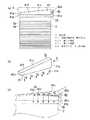
本実施形態の表示装置は、誘導灯として使用される表示装置であって、前面が開口した直方体状の器具本体1を備え、器具本体1の前面の開口の大部分を覆う形で表示ユニット30が配設され、器具本体1の前面の開口のうち表示ユニット30に覆われない部分を覆う形で表示ユニット30の上縁に沿って点光源である発光ダイオード42を有する光源ユニット40が配設されている。  The display device according to the present embodiment is a display device used as a guide light, and includes a rectangularparallelepiped instrument body 1 having an open front surface. Thedisplay unit 30 covers most of the front opening of theinstrument body 1. Alight source unit 40 having alight emitting diode 42 as a point light source is provided along the upper edge of thedisplay unit 30 so as to cover a portion of the opening on the front surface of theinstrument body 1 that is not covered by thedisplay unit 30. Has been.

表示ユニット30は、透光性材料である透明アクリル樹脂で形成された矩形板状の導光板2と、導光板2の前面側に配置された矩形板状の表示パネル3(図2参照)と、導光板2の後面側と、導光板2の下端面を覆う形で配設された反射板(図示せず)と、導光板2、表示パネル3および反射板を保持する合成樹脂で形成されたパネルケース31とを備えている。ここで、導光板2の上端面2bが導光板2の内部に光を入射する一端面を構成しており、導光板2の内部に入射した光は、導光板2の厚み方向の一表面および反射板による反射を繰り返しながら導光板2の内部を伝播するとともに、導光板2の前面から出射される。なお、表示ユニット30は、器具本体1の左右両側壁の内面に突設された被係合片18にパネルケース31の後面に突設された係合片31dが係合した形で器具本体1の前面側に取り付けられる。  Thedisplay unit 30 includes a rectangular plate-shapedlight guide plate 2 formed of a transparent acrylic resin that is a light-transmitting material, and a rectangular plate-shaped display panel 3 (see FIG. 2) disposed on the front side of thelight guide plate 2. Thelight guide plate 2 is formed of a reflection plate (not shown) disposed so as to cover the rear surface side of thelight guide plate 2 and the lower end surface of thelight guide plate 2, and the synthetic resin that holds thelight guide plate 2, thedisplay panel 3, and the reflection plate.Panel case 31. Here, theupper end surface 2b of thelight guide plate 2 constitutes one end surface on which light is incident on the inside of thelight guide plate 2, and the light incident on the inside of thelight guide plate 2 is one surface in the thickness direction of thelight guide plate 2 and While propagating through thelight guide plate 2 while being repeatedly reflected by the reflection plate, the light is emitted from the front surface of thelight guide plate 2. Thedisplay unit 30 includes the instrumentmain body 1 in such a manner that theengagement piece 31d projecting from the rear surface of thepanel case 31 is engaged with the engagedpiece 18 projecting from the inner surfaces of the left and right side walls of the instrumentmain body 1. It is attached to the front side.

導光板2は、透明なアクリル樹脂からなり、上下方向において下側ほど厚みが薄くなるように形成されており、後面には、断面鋸刃形状の横溝2aが上下方向に沿って複数形成されている。ここに、導光板2の上下方向で隣接する横溝2a,2a同士の間隔は、導光板2の上端面2bから下端面側へ遠ざかるほど狭くなるように設定されている。  Thelight guide plate 2 is made of a transparent acrylic resin, and is formed so that the thickness is reduced toward the lower side in the vertical direction, and a plurality ofhorizontal grooves 2a having a sawtooth cross section are formed on the rear surface along the vertical direction. Yes. Here, the interval between thelateral grooves 2a, 2a adjacent to each other in the vertical direction of thelight guide plate 2 is set to become narrower as the distance from theupper end surface 2b to the lower end surface side of thelight guide plate 2 increases.

表示パネル3は、透光性のアクリル製樹脂で形成され、導光板2からの光を表示面3aから前面側へ出射する。また、表示パネル3の表示面3aには避難口へ誘導するためのシンボル(図示せず)が表記されている。  Thedisplay panel 3 is formed of a translucent acrylic resin, and emits light from thelight guide plate 2 from thedisplay surface 3a to the front side. Further, a symbol (not shown) for guiding to the escape port is written on thedisplay surface 3a of thedisplay panel 3.

パネルケース31は、合成樹脂で形成され、左右方向の幅寸法が器具本体1の左右方向の幅寸法と略等しく、上下方向の幅寸法が器具本体1の上下方向の幅寸法よりも小さい平面視矩形状の取付ベース31aと、取付ベース31aの前面の周部において上辺を除いた3辺に沿って前方へ連続一体に突設された保持枠31bとを備えている。また、保持枠31bのうち左右両端部に設けられた部位の内面には、導光板2、表示パネル3および反射板を摺動自在に保持するための案内溝31cが形成されている。なお、保持枠31bの左右両端部に設けられた部位うち、上側に後述の発光ダイオード42が配置される側の一端部に設けられた部位の厚みが、他端部に設けられた部位の厚みに比べて厚さ寸法が大きくなるように設定されている。  Thepanel case 31 is made of a synthetic resin, and has a width dimension in the left-right direction that is substantially equal to a width dimension in the left-right direction of the instrumentmain body 1 and a width dimension in the vertical direction smaller than the width dimension in the vertical direction of theinstrument body 1. Arectangular mounting base 31a and a holdingframe 31b that protrudes continuously and integrally along the three sides excluding the upper side at the periphery of the front surface of the mountingbase 31a are provided. In addition,guide grooves 31c for slidably holding thelight guide plate 2, thedisplay panel 3, and the reflection plate are formed on the inner surfaces of the portions provided on the left and right ends of the holdingframe 31b. In addition, the thickness of the site | part provided in the one end part by the side where the below-mentionedlight emitting diode 42 is arrange | positioned among the site | parts provided in the right and left both ends of the holdingframe 31b is the thickness of the site | part provided in the other end part. The thickness dimension is set so as to be larger than that.

光源ユニット40は、細長の光源ホルダ43の内側に後述の光源用導光板41および点光源である発光ダイオード42が収納されてなる。また、光源ホルダ43は、合成樹脂で形成されている。なお、光源ユニット40は、器具本体1の両側壁の内面における上端部に設けられた被係合部(図示せず)に光源ホルダ43の後面に突設された第2の係合片43aが係合した形で器具本体1の前面側に取り付けられる。  Thelight source unit 40 includes a light sourcelight guide plate 41 to be described later and alight emitting diode 42 as a point light source inside an elongatedlight source holder 43. Thelight source holder 43 is made of synthetic resin. Thelight source unit 40 includes a secondengaging piece 43 a that protrudes from the rear surface of thelight source holder 43 at an engaged portion (not shown) provided at the upper end portion of the inner surface of both side walls of theinstrument body 1. It is attached to the front side of theinstrument body 1 in an engaged form.

器具本体1の内部には、発光ダイオード42を点灯させるための電源回路(図示せず)を有する点灯装置5が配設されている。また、器具本体1の内部には、商用電源(図示せず)の停電時に点灯装置5へ給電するための非常用電源たる蓄電池を有する非常用電源ブロック6が配設されている。ここに、点灯装置5は、商用電源に接続される端子台7に電線(図示せず)を介して接続されるとともに、非常用電源ブロック6にも電線(図示せず)を介して接続されており、通常は商用電源により給電されて発光ダイオード42を点灯させて、商用電源の停電時には蓄電池により給電されて発光ダイオード42を点灯させるように構成されている。  A lighting device 5 having a power supply circuit (not shown) for lighting thelight emitting diode 42 is disposed inside thefixture body 1. In addition, an emergency power supply block 6 having a storage battery as an emergency power supply for supplying power to the lighting device 5 in the event of a power failure of a commercial power supply (not shown) is disposed inside the appliancemain body 1. Here, the lighting device 5 is connected to a terminal block 7 connected to a commercial power source via an electric wire (not shown), and also connected to the emergency power supply block 6 via an electric wire (not shown). In general, the light-emittingdiode 42 is turned on by being fed by a commercial power source, and the light-emittingdiode 42 is turned on by being fed by a storage battery in the event of a power failure of the commercial power source.

ところで、本実施形態の表示装置には、導光板2の上端面2bに対向して配置されるとともに点光源である発光ダイオード42が、導光板2の上端面2bに沿った長手方向における一端側に配置され、発光ダイオード42から入射した光を導光板2の上端面2b側に導光する導光部材である光源用導光板41が設けられている。  By the way, in the display device of the present embodiment, thelight emitting diode 42 that is arranged to face theupper end surface 2b of thelight guide plate 2 and is a point light source is on one end side in the longitudinal direction along theupper end surface 2b of thelight guide plate 2. A light sourcelight guide plate 41 that is a light guide member that guides light incident from thelight emitting diode 42 to theupper end surface 2 b side of thelight guide plate 2 is provided.

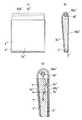
光源用導光板41は、透明なアクリル樹脂で形成され、厚さ寸法が導光板2と略同じ厚さ寸法に設定されている。また、導光板2の上端面2bと平行する第1の端面42bと、導光板2側とは反対側の第2の端面41cとの間の距離が、前記長手方向における他端側に近づくほど小さくなる形に形成されている。つまり、光源用導光板41の第2の端面41cは、光源用導光板41の第1の端面41bに対して傾斜している。ここで、光源用導光板41は、図1(b)に示すように、光源用導光板41の前記長手方向における前記一端側に、発光ダイオード42からの光(図1(b)の矢印A)が入射する第3の端面41aが形成されており、第3の端面41aから光源用導光板41に入射した光は、第1の端面41b全体から出射される(図1(b)の矢印B)。光源用導光板41の第1の端面41bは、細長の長方形状であり、光源用導光板41と発光ダイオード42とで線状光源4を構成している。  Thelight guide plate 41 for the light source is formed of a transparent acrylic resin, and the thickness dimension is set to be substantially the same as that of thelight guide plate 2. Further, the distance between the first end surface 42b parallel to theupper end surface 2b of thelight guide plate 2 and thesecond end surface 41c opposite to thelight guide plate 2 side becomes closer to the other end side in the longitudinal direction. It is formed in a smaller shape. That is, thesecond end surface 41 c of the light sourcelight guide plate 41 is inclined with respect to thefirst end surface 41 b of the light sourcelight guide plate 41. Here, as shown in FIG. 1B, the light sourcelight guide plate 41 has light from the light emitting diode 42 (arrow A in FIG. 1B) on the one end side in the longitudinal direction of the light source light guide plate 41. ) Is formed, and light incident on the light sourcelight guide plate 41 from thethird end surface 41a is emitted from the entirefirst end surface 41b (arrow in FIG. 1B). B). Thefirst end face 41 b of the light sourcelight guide plate 41 has an elongated rectangular shape, and the light sourcelight guide plate 41 and thelight emitting diode 42 constitute the linearlight source 4.

また、光源用導光板41の第2の端面41cには、断面鋸刃状に形成され且つ光源用導光板41の内側を導光する光を光源用導光板41の第1の端面41b側へ反射する光反射用溝41eが形成されている。なお、本実施形態では、光源用導光板41の第2の端面41cに断面鋸刃状の光反射溝41eを形成する場合について説明したが、これに限定されず、光を拡散させるドットを形成してもよい。  Further, light that is formed in a sawtooth shape in cross section on thesecond end surface 41 c of the light sourcelight guide plate 41 and guides the light sourcelight guide plate 41 to the inner side of the light sourcelight guide plate 41 toward thefirst end surface 41 b side of the light sourcelight guide plate 41. A light reflecting groove 41e for reflection is formed. In the present embodiment, the case where the light reflection groove 41e having a sawtooth cross section is formed on thesecond end surface 41c of thelight guide plate 41 for the light source has been described. However, the present invention is not limited to this, and dots that diffuse light are formed. May be.

点光源である発光ダイオード42としては、白色発光ダイオードが使用され、例えば、セラミックス基板42aに凹部(図示せず)を形成し、当該凹部の内側にGaN系化合物半導体を利用した発光ダイオード素子(図示せず)を配設するとともに、黄色蛍光体からなる蛍光物質を含む透光性のシリコーン樹脂(図示せず)を充填することで形成される白色発光ダイオードが使用されている。なお、発効ダイオード42の構成は、本実施形態で説明したものに限定されない。また、本実施形態では、点光源として発光ダイオード42を使用する例について説明したが、これに限定されるものではなく、例えば、有機EL光源等を使用してもよい。  As thelight emitting diode 42 which is a point light source, a white light emitting diode is used. For example, a concave portion (not shown) is formed in theceramic substrate 42a, and a light emitting diode element using a GaN-based compound semiconductor (see FIG. And a white light emitting diode formed by filling a translucent silicone resin (not shown) containing a fluorescent substance made of a yellow phosphor. In addition, the structure of theeffective diode 42 is not limited to what was demonstrated in this embodiment. In this embodiment, the example in which thelight emitting diode 42 is used as the point light source has been described. However, the present invention is not limited to this, and for example, an organic EL light source or the like may be used.

本実施形態の表示装置では、従来の表示装置のように、複数の点光源である発光ダイオード42”を導光板2”の上端面の長手方向に沿って並設した場合に比べて、導光板2の上端面2b全体における入射光強度の均一性を高めることができるので、表示パネル3の表示面3a全体の輝度の均一性を向上させることができる。  In the display device of the present embodiment, as compared with the conventional display device, thelight guide plate 42 ″, which is a plurality of point light sources, is arranged in parallel along the longitudinal direction of the upper end surface of thelight guide plate 2 ″. 2 can improve the uniformity of the incident light intensity on the entireupper end surface 2b of thedisplay panel 3. Therefore, the uniformity of the luminance on theentire display surface 3a of thedisplay panel 3 can be improved.

また、光源用導光板41の第2の端面41cは、前述のように、光源用導光板41の第1の端面41bに対して傾斜していることにより、導光板2の上端面2bに沿った長手方向における他端側に近づくほど光源用導光板41の第2の端面41cでの光の反射角が小さくなるとともに光源用導光板41の第1の端面41bへの光の入射角が小さくなるので、前記長手方向の他端側ほど光源用導光板41の内部から光を出射しやすくなり、第1の端面41bにおいて発光ダイオード42から遠い前記長手方向の他端側においても光源用導光板41の第1の端面41bからの出射光の強度が減衰することがなく、導光板2の上端面2c全体における入射光強度の均一性を更に高めることができる。  Further, as described above, thesecond end surface 41c of the light sourcelight guide plate 41 is inclined with respect to thefirst end surface 41b of the light sourcelight guide plate 41, thereby being along theupper end surface 2b of thelight guide plate 2. The closer to the other end side in the longitudinal direction, the smaller the light reflection angle at thesecond end face 41c of the light sourcelight guide plate 41 and the smaller the incident angle of light on thefirst end face 41b of the light sourcelight guide plate 41. Therefore, it becomes easier to emit light from the inside of the light sourcelight guide plate 41 toward the other end side in the longitudinal direction, and the light source light guide plate also on the other end side in the longitudinal direction far from thelight emitting diode 42 on thefirst end face 41b. The intensity of the emitted light from thefirst end surface 41b of 41 is not attenuated, and the uniformity of the incident light intensity on the entire upper end surface 2c of thelight guide plate 2 can be further enhanced.

更に、光源用導光板41の厚み方向の両側表面41f,41fと、第2の端面41cと、第3の端面41aに対向する第4の端面41dとは、反射率が高くなっている。従って、光源用導光板41の内側を導光してきた光は、光源用導光板41の第2の端面41cで反射されるとともに、光源用導光板41の厚み方向の両側表面41f,41fと、第4の端面41dとにおいて、光源用導光板41の内側に反射され、外側へ漏れ出すことが防止することができる。しかして、発光ダイオード42から光源用導光板41に入射した光を光源用導光板41の第1の端面41bから出射する効率を更に向上させることができるので、省エネルギ化を図ることができる。  Furthermore, the bothside surfaces 41f and 41f in the thickness direction of thelight guide plate 41 for light source, thesecond end surface 41c, and thefourth end surface 41d facing thethird end surface 41a have high reflectance. Therefore, the light guided inside the light sourcelight guide plate 41 is reflected by thesecond end face 41c of the light sourcelight guide plate 41, and bothside surfaces 41f, 41f in the thickness direction of the light sourcelight guide plate 41, It is possible to prevent thefourth end surface 41d from being reflected inside the light sourcelight guide plate 41 and leaking outside. Thus, since the efficiency of emitting the light incident on the light sourcelight guide plate 41 from thelight emitting diode 42 from thefirst end face 41b of the light sourcelight guide plate 41 can be further improved, energy saving can be achieved.

本実施形態の表示装置では、点光源として発光ダイオード42を使用するので、一般の冷陰極蛍光灯を光源に使用した表示装置に比べて、消費電力が小さいから、省エネルギ化が図れる。  In the display device of this embodiment, since thelight emitting diode 42 is used as a point light source, the power consumption is smaller than that of a display device using a general cold cathode fluorescent lamp as a light source, so that energy saving can be achieved.

ところで、図8に示す構成の表示装置では、点光源である複数の発光ダイオード42”を導光板2”の上端面の長手方向に沿って一直線上に配置した構成としている。この場合、表示パネル3”の表示面3a”全体の輝度の均一性を向上させるために、発光ダイオード42”の数を増やして、隣接する各発光ダイオード42”,42”の間隔を狭くすることで、複数の発光ダイオード42”の間に生じる非発光部を小さくする必要がある。この場合、部品点数が増加するので、コスト上昇を招く可能性が大きい。  By the way, in the display device having the configuration shown in FIG. 8, a plurality oflight emitting diodes 42 ″ as point light sources are arranged in a straight line along the longitudinal direction of the upper end surface of thelight guide plate 2 ″. In this case, in order to improve the luminance uniformity of theentire display surface 3a ″ of thedisplay panel 3 ″, the number of thelight emitting diodes 42 ″ is increased and the interval between the adjacentlight emitting diodes 42 ″ and 42 ″ is reduced. Therefore, it is necessary to reduce the non-light emitting portion generated between the plurality oflight emitting diodes 42 ″. In this case, since the number of parts increases, there is a high possibility that the cost will increase.

これに対して、本実施形態の表示装置は、発光ダイオード42が少なくとも1個あればよく、部品点数を削減することができるので、コスト低減を図ることができる。  On the other hand, the display device of the present embodiment only needs at least onelight emitting diode 42, and the number of parts can be reduced, so that the cost can be reduced.

また、本実施形態の表示装置では、前述のように、一般の冷陰極蛍光灯を使用した表示装置に比べて、消費電力が小さいので、非常用電源ブロック6(図2参照)の有する蓄電池の容量を低減することができる。従って、非常用電源ブロック6の有する蓄電池を充電に使用される電力消費量を小さくすることができるので、省エネルギ化を図ることができる。  Further, as described above, the display device according to the present embodiment consumes less power than a display device using a general cold cathode fluorescent lamp, so that the storage battery of the emergency power supply block 6 (see FIG. 2) has a low power consumption. The capacity can be reduced. Therefore, since the power consumption used for charging the storage battery of the emergency power supply block 6 can be reduced, energy saving can be achieved.

(実施形態2)
本実施形態の表示装置の基本構成は、実施形態1と略同じであり、図3に示すように、金属で形成され且つ内面全体に反射面44aが形成された円筒部材の側壁に円筒部材の軸方向に沿って細長のスリット44bが形成された導光部材44を備え、導光部材44が導光板2の上端面2bに対向して配置される点が相違する。ここで、導光板2の上端面2bが導光板2の内部に光を入射する一端面を構成している。
(Embodiment 2)
The basic configuration of the display device of the present embodiment is substantially the same as that of the first embodiment. As shown in FIG. 3, the cylindrical member is formed on the side wall of the cylindrical member formed of metal and having thereflection surface 44a formed on the entire inner surface. Alight guide member 44 in which anelongated slit 44 b is formed along the axial direction is provided, and thelight guide member 44 is different from theupper end surface 2 b of thelight guide plate 2. Here, theupper end surface 2 b of thelight guide plate 2 constitutes one end surface on which light enters thelight guide plate 2.

ここにおいて、点光源である発光ダイオード42から導光部材44の内側へ入射した光は、導光部材44の内面全体に形成された反射面44aで反射を繰り返しながら、導光部材44の内側を導光するとともに、導光部材44の内側を導光する光の一部がスリット44bから導光板2の上端面2b側へ出射される(図3(a)(b)の矢印)。即ち、点光源である発光ダイオード42と導光部材44とで、細長のスリット44b全体から光を出射する線状光源4を構成している。  Here, the light incident on the inside of thelight guide member 44 from thelight emitting diode 42 as a point light source is repeatedly reflected by thereflection surface 44 a formed on the entire inner surface of thelight guide member 44, while passing through the inside of thelight guide member 44. A part of the light that is guided and guided inside thelight guide member 44 is emitted from theslit 44b to theupper end surface 2b side of the light guide plate 2 (arrows in FIGS. 3A and 3B). That is, the light-emittingdiode 42 that is a point light source and thelight guide member 44 constitute a linearlight source 4 that emits light from the entireelongated slit 44b.

本実施形態の表示装置では、従来の表示装置のように、複数の点光源である発光ダイオード42”を導光板2”の上端面の長手方向に沿って並設した場合に比べて、導光板2の上端面2b全体における入射光強度の均一性を高めることができるので、表示パネル3の表示面3a全体の輝度の均一性を向上させることができる。  In the display device of the present embodiment, as compared with the conventional display device, thelight guide plate 42 ″, which is a plurality of point light sources, is arranged in parallel along the longitudinal direction of the upper end surface of thelight guide plate 2 ″. 2 can improve the uniformity of the incident light intensity on the entireupper end surface 2b of thedisplay panel 3. Therefore, the uniformity of the luminance on theentire display surface 3a of thedisplay panel 3 can be improved.

なお、上記各実施形態では、誘導灯として使用される表示装置について説明したが、これに限定されるものではなく、例えば、サインとして使用される表示装置であってもよい。  In addition, although each said embodiment demonstrated the display apparatus used as a guide light, it is not limited to this, For example, the display apparatus used as a sign may be sufficient.

実施形態1の表示装置を示し、(a)は要部概略正面図、(b)は要部概略斜視図、(c)は動作説明図である。The display apparatus ofEmbodiment 1 is shown, (a) is a principal part schematic front view, (b) is a principal part schematic perspective view, (c) is operation | movement explanatory drawing.同上の分解斜視図である。It is an exploded perspective view same as the above.実施形態2の表示装置を示し、(a)は要部概略正面図、(b)は要部概略断面図である。The display apparatus ofEmbodiment 2 is shown, (a) is a principal part schematic front view, (b) is a principal part schematic sectional drawing.従来例を示し、(a)は概略断面図、(b)は動作説明図である。A prior art example is shown, (a) is a schematic sectional view, and (b) is an operation explanatory diagram.他の従来例を示し、(a)は概略正面図、(b)は概略断面図、(c)は動作説明図である。Another example is shown, (a) is a schematic front view, (b) is a schematic cross-sectional view, and (c) is an operation explanatory diagram.同上の表示装置について、(a)は横溝方式の導光板の概略正面図、(b)は拡散方式の導光板の概略正面図、(c),(e)は横溝方式の導光板を使用した場合の配光特性を示す図、(d),(f)は拡散方式の導光板を使用した場合の配光特性を示す図である。About the display device same as the above, (a) is a schematic front view of a horizontal groove type light guide plate, (b) is a schematic front view of a diffusion type light guide plate, and (c) and (e) use a horizontal groove type light guide plate. The figure which shows the light distribution characteristic in a case, (d), (f) is a figure which shows the light distribution characteristic at the time of using a diffusion-type light-guide plate.同上の課題を説明するための図である。It is a figure for demonstrating the subject same as the above.他の従来例を示し、(a)は概略分解斜視図、(b)は横溝方式の導光板を使用した表示装置の動作説明図、(c)は拡散方式の導光板を使用した表示装置の動作説明図である。Other conventional examples are shown, (a) is a schematic exploded perspective view, (b) is an operation explanatory diagram of a display device using a lateral groove type light guide plate, (c) is a display device using a diffusion type light guide plate. It is operation | movement explanatory drawing.

符号の説明Explanation of symbols

1 器具本体
2 導光板
2b 上端面(一端面)
3 表示パネル
4 線状光源
5 点灯装置
6 非常用電源ブロック
30 表示ユニット
40 光源ユニット
41 光源用導光板(導光部材)
41b 第1の端面
41c 第2の端面
41e 光反射用溝
42 発光ダイオード(点光源)


DESCRIPTION OFSYMBOLS 1Apparatus body 2 Light-guide plate 2b Upper end surface (one end surface)
3Display panel 4 Linear light source 5 Lighting device 6 Emergencypower supply block 30Display unit 40Light source unit 41 Light guide plate for light source (light guide member)
41bFirst end face 41c Second end face 41eLight reflecting groove 42 Light emitting diode (point light source)


Claims (2)

Translated fromJapanese
透光性材料で形成され且つ一端面に入射される光を厚み方向の一表面側に出射する導光板と、導光板の前記一表面側に配置され且つ導光板の前記一表面から出射される光を表示面から前面側へ出射するための表示パネルとを備え、導光板の前記一端面に対向して配置されるとともに導光板の前記一端面に沿った長手方向における一端側に配置された点光源から入射した光を導光板の前記一端面の全体に導光する導光部材を有することを特徴とする表示装置。  A light guide plate that is formed of a translucent material and that emits light incident on one end surface to one surface side in the thickness direction, and is disposed on the one surface side of the light guide plate and is emitted from the one surface of the light guide plate A display panel for emitting light from the display surface to the front surface side, disposed opposite to the one end surface of the light guide plate and disposed on one end side in the longitudinal direction along the one end surface of the light guide plate A display device comprising a light guide member that guides light incident from a point light source to the entire one end surface of the light guide plate. 前記導光部材は、透光性材料で形成され、前記導光板の前記一端面に平行する前記導光板側の第1の端面と、前記導光板側とは反対側の第2の端面との間の距離が、前記長手方向における他端側に近づくほど短くなる形に形成されてなる光源用導光板であることを特徴とする請求項1記載の表示装置。


The light guide member is formed of a translucent material, and includes a first end surface on the light guide plate side parallel to the one end surface of the light guide plate, and a second end surface opposite to the light guide plate side. 2. The display device according to claim 1, wherein the light guide plate for a light source is formed such that a distance therebetween becomes shorter as approaching the other end side in the longitudinal direction.


JP2008276021A2008-10-272008-10-27Display devicePendingJP2010103060A (en)

Priority Applications (1)

Application NumberPriority DateFiling DateTitle
JP2008276021AJP2010103060A (en)2008-10-272008-10-27Display device

Applications Claiming Priority (1)

Application NumberPriority DateFiling DateTitle
JP2008276021AJP2010103060A (en)2008-10-272008-10-27Display device

Publications (1)

Publication NumberPublication Date
JP2010103060Atrue JP2010103060A (en)2010-05-06

Family

ID=42293527

Family Applications (1)

Application NumberTitlePriority DateFiling Date
JP2008276021APendingJP2010103060A (en)2008-10-272008-10-27Display device

Country Status (1)

CountryLink
JP (1)JP2010103060A (en)

Cited By (5)

* Cited by examiner, † Cited by third party
Publication numberPriority datePublication dateAssigneeTitle
WO2013122729A1 (en)*2012-02-172013-08-223M Innovative Properties CompanyBacklight system
WO2013122728A1 (en)*2012-02-172013-08-223M Innovative Properties CompanyAnamorphic light guide
KR20180072356A (en)*2016-12-212018-06-29삼성전자주식회사Backlight unit and three-dimensional image display apparatus including the same
JP2020087893A (en)*2018-11-302020-06-04パナソニックIpマネジメント株式会社 Light source unit and display device including the same
JP7473880B2 (en)2020-08-282024-04-24東芝ライテック株式会社 Exit sign

Citations (4)

* Cited by examiner, † Cited by third party
Publication numberPriority datePublication dateAssigneeTitle
JPH11231320A (en)*1998-02-121999-08-27Enplas CorpSide light type planar light source unit and liquid crystal display device
JPH11312402A (en)*1998-04-301999-11-09Matsushita Electric Works LtdLuminaire
JP2001057106A (en)*1999-08-192001-02-27Minebea Co LtdSurface lighting system
JP2008524831A (en)*2004-12-222008-07-10松下電器産業株式会社 Semiconductor light emitting device, illumination module, illumination device, method for manufacturing semiconductor light emitting device, and method for manufacturing semiconductor light emitting element

Patent Citations (4)

* Cited by examiner, † Cited by third party
Publication numberPriority datePublication dateAssigneeTitle
JPH11231320A (en)*1998-02-121999-08-27Enplas CorpSide light type planar light source unit and liquid crystal display device
JPH11312402A (en)*1998-04-301999-11-09Matsushita Electric Works LtdLuminaire
JP2001057106A (en)*1999-08-192001-02-27Minebea Co LtdSurface lighting system
JP2008524831A (en)*2004-12-222008-07-10松下電器産業株式会社 Semiconductor light emitting device, illumination module, illumination device, method for manufacturing semiconductor light emitting device, and method for manufacturing semiconductor light emitting element

Cited By (13)

* Cited by examiner, † Cited by third party
Publication numberPriority datePublication dateAssigneeTitle
WO2013122729A1 (en)*2012-02-172013-08-223M Innovative Properties CompanyBacklight system
WO2013122728A1 (en)*2012-02-172013-08-223M Innovative Properties CompanyAnamorphic light guide
TWI581040B (en)*2012-02-172017-05-013M新設資產公司Backlight system
US9817173B2 (en)2012-02-172017-11-143M Innovative Properties CompanyAnamorphic light guide
US9823404B2 (en)2012-02-172017-11-213M Innovative Properties CompanyBacklight system
CN108227219A (en)*2016-12-212018-06-29三星电子株式会社Optical beam expander, back light unit and the holographic display including the back light unit
KR20180072356A (en)*2016-12-212018-06-29삼성전자주식회사Backlight unit and three-dimensional image display apparatus including the same
EP3339964A3 (en)*2016-12-212018-10-24Samsung Electronics Co., Ltd.Backlight unit and holographic display device including the same
US10459288B2 (en)2016-12-212019-10-29Samsung Electronics Co., Ltd.Backlight unit and holographic display device including the same
KR102739947B1 (en)*2016-12-212024-12-06삼성전자주식회사Backlight unit and three-dimensional image display apparatus including the same
JP2020087893A (en)*2018-11-302020-06-04パナソニックIpマネジメント株式会社 Light source unit and display device including the same
JP7133788B2 (en)2018-11-302022-09-09パナソニックIpマネジメント株式会社 Light source unit and display device provided with the same
JP7473880B2 (en)2020-08-282024-04-24東芝ライテック株式会社 Exit sign

Similar Documents

PublicationPublication DateTitle
US8226282B2 (en)Vehicle lamp
JP2009099271A (en) Hollow surface lighting device
JP2007234385A (en)Backlight device
JP2009026708A (en)Light source device
JP2008293767A (en)Light-emitting device
CN101832517B (en)Back light module
TW201341720A (en)LED fluorescent illumination device
JP2010103060A (en)Display device
JP2009187718A (en)Light source device
JP6198120B2 (en) Light emitting module and lighting device using the same
KR100971707B1 (en) The bar-
JP2010522961A (en) General lighting system and lighting fixture
JP2015002138A (en)Luminaire, task light and wall surface mounting luminaire
JP2009181916A (en)Light source system
JP6114575B2 (en) lighting equipment
JP6041082B2 (en) Lighting device
JP2012243679A (en)Lighting system
JP2012243680A (en)Lighting system
JP2005310680A (en)Light-emitting diode lighting device
JP5950529B2 (en) Surface light source device and display device including the same
KR200444467Y1 (en) Luminous glass plate
TWI409412B (en)Led illuminating device
JP5383758B2 (en) Lighting device
JP2007123133A (en)Light panel
JP6048935B2 (en) Lighting device

Legal Events

DateCodeTitleDescription
RD04Notification of resignation of power of attorney

Free format text:JAPANESE INTERMEDIATE CODE: A7424

Effective date:20100715

A621Written request for application examination

Free format text:JAPANESE INTERMEDIATE CODE: A621

Effective date:20111020

A711Notification of change in applicant

Free format text:JAPANESE INTERMEDIATE CODE: A712

Effective date:20120112

A977Report on retrieval

Free format text:JAPANESE INTERMEDIATE CODE: A971007

Effective date:20121220

A131Notification of reasons for refusal

Free format text:JAPANESE INTERMEDIATE CODE: A131

Effective date:20130122

A521Written amendment

Free format text:JAPANESE INTERMEDIATE CODE: A523

Effective date:20130325

A131Notification of reasons for refusal

Free format text:JAPANESE INTERMEDIATE CODE: A131

Effective date:20131001

A521Written amendment

Free format text:JAPANESE INTERMEDIATE CODE: A523

Effective date:20131202

A131Notification of reasons for refusal

Free format text:JAPANESE INTERMEDIATE CODE: A131

Effective date:20140325

A521Written amendment

Free format text:JAPANESE INTERMEDIATE CODE: A523

Effective date:20140526

A711Notification of change in applicant

Free format text:JAPANESE INTERMEDIATE CODE: A711

Effective date:20141007

A02Decision of refusal

Free format text:JAPANESE INTERMEDIATE CODE: A02

Effective date:20141111


[8]ページ先頭

©2009-2025 Movatter.jp