JP2010102479A - Computer system, storage device, and data updating method - Google Patents
Computer system, storage device, and data updating methodDownload PDFInfo
- Publication number
- JP2010102479A JP2010102479AJP2008272846AJP2008272846AJP2010102479AJP 2010102479 AJP2010102479 AJP 2010102479AJP 2008272846 AJP2008272846 AJP 2008272846AJP 2008272846 AJP2008272846 AJP 2008272846AJP 2010102479 AJP2010102479 AJP 2010102479A
- Authority
- JP
- Japan
- Prior art keywords
- area
- volume
- storage
- data
- update
- Prior art date
- Legal status (The legal status is an assumption and is not a legal conclusion. Google has not performed a legal analysis and makes no representation as to the accuracy of the status listed.)
- Pending
Links
Images


Classifications
- G—PHYSICS
- G06—COMPUTING OR CALCULATING; COUNTING
- G06F—ELECTRIC DIGITAL DATA PROCESSING
- G06F11/00—Error detection; Error correction; Monitoring
- G06F11/07—Responding to the occurrence of a fault, e.g. fault tolerance
- G06F11/14—Error detection or correction of the data by redundancy in operation
- G06F11/1402—Saving, restoring, recovering or retrying
- G06F11/1446—Point-in-time backing up or restoration of persistent data
- G06F11/1458—Management of the backup or restore process
- G—PHYSICS
- G06—COMPUTING OR CALCULATING; COUNTING
- G06F—ELECTRIC DIGITAL DATA PROCESSING
- G06F11/00—Error detection; Error correction; Monitoring
- G06F11/07—Responding to the occurrence of a fault, e.g. fault tolerance
- G06F11/14—Error detection or correction of the data by redundancy in operation
- G06F11/1402—Saving, restoring, recovering or retrying
- G06F11/1446—Point-in-time backing up or restoration of persistent data
- G06F11/1448—Management of the data involved in backup or backup restore
- G—PHYSICS
- G06—COMPUTING OR CALCULATING; COUNTING
- G06F—ELECTRIC DIGITAL DATA PROCESSING
- G06F11/00—Error detection; Error correction; Monitoring
- G06F11/07—Responding to the occurrence of a fault, e.g. fault tolerance
- G06F11/16—Error detection or correction of the data by redundancy in hardware
- G06F11/20—Error detection or correction of the data by redundancy in hardware using active fault-masking, e.g. by switching out faulty elements or by switching in spare elements
- G06F11/2002—Error detection or correction of the data by redundancy in hardware using active fault-masking, e.g. by switching out faulty elements or by switching in spare elements where interconnections or communication control functionality are redundant
- G06F11/2005—Error detection or correction of the data by redundancy in hardware using active fault-masking, e.g. by switching out faulty elements or by switching in spare elements where interconnections or communication control functionality are redundant using redundant communication controllers
- G—PHYSICS
- G06—COMPUTING OR CALCULATING; COUNTING
- G06F—ELECTRIC DIGITAL DATA PROCESSING
- G06F11/00—Error detection; Error correction; Monitoring
- G06F11/07—Responding to the occurrence of a fault, e.g. fault tolerance
- G06F11/16—Error detection or correction of the data by redundancy in hardware
- G06F11/20—Error detection or correction of the data by redundancy in hardware using active fault-masking, e.g. by switching out faulty elements or by switching in spare elements
- G06F11/2002—Error detection or correction of the data by redundancy in hardware using active fault-masking, e.g. by switching out faulty elements or by switching in spare elements where interconnections or communication control functionality are redundant
- G06F11/2007—Error detection or correction of the data by redundancy in hardware using active fault-masking, e.g. by switching out faulty elements or by switching in spare elements where interconnections or communication control functionality are redundant using redundant communication media
- G06F11/201—Error detection or correction of the data by redundancy in hardware using active fault-masking, e.g. by switching out faulty elements or by switching in spare elements where interconnections or communication control functionality are redundant using redundant communication media between storage system components
- G—PHYSICS
- G06—COMPUTING OR CALCULATING; COUNTING
- G06F—ELECTRIC DIGITAL DATA PROCESSING
- G06F2201/00—Indexing scheme relating to error detection, to error correction, and to monitoring
- G06F2201/84—Using snapshots, i.e. a logical point-in-time copy of the data
Landscapes
- Engineering & Computer Science (AREA)
- Theoretical Computer Science (AREA)
- Quality & Reliability (AREA)
- Physics & Mathematics (AREA)
- General Engineering & Computer Science (AREA)
- General Physics & Mathematics (AREA)
- Information Retrieval, Db Structures And Fs Structures Therefor (AREA)
Abstract
Translated fromJapaneseDescription
Translated fromJapanese本発明は、複数の記憶領域を提供する計算機システムに関し、特に、各記憶領域を一括して更新する技術に関する。 The present invention relates to a computer system that provides a plurality of storage areas, and more particularly to a technique for updating each storage area in a batch.
データの損失を防ぐために、データを格納するボリュームのバックアップを作成する方法の一つとして、スナップショットを作成することが挙げられる。スナップショットとは、バックアップ作成時点のボリュームのイメージである。スナップショットは、ファイルシステムの損傷などを修復するために利用されるため、通常、読み取り専用である。 In order to prevent data loss, one method for creating a backup of a volume storing data is to create a snapshot. A snapshot is an image of a volume at the time of backup creation. Snapshots are typically read-only because they are used to repair file system damage and the like.
また、スナップショットは、バックアップを目的とせずにデータの複製を利用する場合に活用することができる。例えば、複数のテスト環境を構築する場合などである。しかし、スナップショットは前述のように、通常、読み取り専用であるため、テストデータと利用するためには、更新可能であると都合がよい。 Snapshots can be used when data replication is used without the purpose of backup. For example, when a plurality of test environments are constructed. However, since the snapshot is usually read-only as described above, it is convenient that the snapshot can be updated for use with the test data.
特許文献1には、オリジナルの読み取り専用のスナップショットに加え、更新されたデータを格納する差分ボリュームを備えることによって、更新可能なスナップショットを提供する技術が開示されている。特許文献1に開示された技術では、複数のスナップショットを提供する場合には、提供されたスナップショットごとに差分ボリュームの領域を確保し、更新データを格納することによって個別に対応することができる。
具体例として、3つの開発チームでソフトウェアを開発する場合に、特許文献1に開示された技術を適用する場合について説明する。また、各開発チームでは、もともと存在するベースとなるプログラムを利用して開発を行う。このとき、ベースとなるプログラム(オリジナルデータ)の複製(スナップショット)を開発チームごとに3つ作成し、1つのオリジナルデータをそれぞれポイントする。そして、ある開発チームがオリジナルデータに変更を加えた場合には、変更されたデータを差分として差分ボリュームに格納することによってスナップショットを更新することができる。
特許文献1に開示された技術では、生成されたスナップショットごと、すなわち、開発チームごとに差分が格納されるため、ある開発チームによって変更されたデータを他の開発チームで参照することができない。他の開発チームで変更された内容を反映させるためには、データを変更した開発チームで行われた操作を再度実行し、変更されたデータを参照しようとする開発チームに対応する差分ボリュームに改めて格納する必要がある。したがって、すべての開発チームで同じ変更データを参照するためには、すべての開発チームで同じ操作を実行する必要がある。 In the technique disclosed in
すなわち、一つのスナップショットにおける更新データをすべてのスナップショットに反映させるためには、差分ボリュームのすべてのスナップショットに対応する領域を更新しなければならない。したがって、スナップショットの数(開発チームの数)だけ更新データを格納しなければならないため、必要な記憶容量が増大してしまう。 That is, in order to reflect the update data in one snapshot in all the snapshots, the areas corresponding to all the snapshots in the differential volume must be updated. Therefore, since the update data must be stored by the number of snapshots (the number of development teams), the necessary storage capacity increases.
本発明は、以上の問題を鑑みてなされたものであり、複数の更新可能なスナップショットが提供されている場合に、必要に応じてすべてのスナップショットに更新内容を効率的に反映させることを目的とする。 The present invention has been made in view of the above problems, and when a plurality of updatable snapshots are provided, the updated contents are efficiently reflected in all the snapshots as necessary. Objective.
本発明の代表的な一形態では、データを読み書きするための複数の記憶領域(更新可能スナップショット)を提供する計算機と、前記記憶領域に読み書きされるデータを格納するストレージ装置とを含む計算機システムであって、前記計算機は、前記ストレージ装置に接続される第1のインターフェースと、前記第1のインターフェースに接続される第1のプロセッサと、前記第1のプロセッサに接続される第1のメモリと、を備え、前記ストレージ装置は、前記計算機に接続される第2のインターフェースと、前記第2のインターフェースに接続される第2のプロセッサと、前記第2のプロセッサに接続される第2のメモリと、を備え、前記ストレージ装置は、前記各記憶領域に共有されるデータ(オリジナルデータ)を格納する第1のボリュームと、前記各記憶領域で保持されるデータ(差分データ)を格納する第2のボリュームとを前記計算機に提供し、前記第1のメモリには、前記各記憶領域を管理する記憶領域管理情報(スナップショット管理情報)と、前記データの更新を受け付けた場合に更新データの格納先を設定する格納先フラグとが記憶され、前記第1のプロセッサは、前記データの格納先の指定を受け付けると、前記指定された格納先に基づいて、前記格納先フラグを設定し、前記第1のボリュームに格納されたデータの更新を受け付け、かつ、前記格納先フラグが前記第1のボリュームに設定されている場合には、前記第1のボリュームの更新対象である第1の領域を特定し、前記特定された第1の領域を更新し、前記第1のボリュームに格納されたデータの更新を受け付け、かつ、前記格納先フラグが前記第2のボリュームに設定されている場合には、前記記憶領域管理情報に基づいて、前記第1の領域に対応する第2の領域が前記第2のボリュームに割り当てられているか否かを判定し、前記第2のボリュームに前記第2の領域が割り当てられている場合には、前記第2の領域を更新し、前記第2のボリュームに前記第2の領域が割り当てられていない場合には、前記第2のボリュームに前記第2の領域を新たに割り当て、前記新たに割り当てられた第2の領域を更新し、前記新たに割り当てられた第2の領域の位置情報を前記第1の領域に対応させて前記記憶領域管理情報に格納する。 In a typical embodiment of the present invention, a computer system including a computer that provides a plurality of storage areas (updatable snapshots) for reading and writing data, and a storage device that stores data to be read and written to the storage areas. The computer includes a first interface connected to the storage device, a first processor connected to the first interface, and a first memory connected to the first processor. The storage device includes a second interface connected to the computer, a second processor connected to the second interface, and a second memory connected to the second processor. The storage device includes a first box for storing data (original data) shared by the storage areas. Storage area management information for managing each storage area in the first memory, and a second volume for storing data stored in each storage area (difference data). (Snapshot management information) and a storage destination flag for setting a storage location of update data when the update of the data is received, and the first processor receives the specification of the storage location of the data The storage destination flag is set based on the designated storage destination, the update of the data stored in the first volume is accepted, and the storage destination flag is set in the first volume. If there is, the first area to be updated of the first volume is specified, the specified first area is updated, and the data stored in the first volume is stored. When the update is accepted and the storage destination flag is set in the second volume, the second area corresponding to the first area is determined based on the storage area management information. And if the second area is assigned to the second volume, the second area is updated, and the second volume is updated to the second volume. If the second area is not allocated, the second area is newly allocated to the second volume, the newly allocated second area is updated, and the newly allocated second area is updated. Is stored in the storage area management information in correspondence with the first area.
本発明の一形態によれば、複数の記憶領域(更新可能スナップショット)が提供されている場合に、必要に応じてすべての記憶領域に対して効率的に更新内容を反映させることができる。 According to an aspect of the present invention, when a plurality of storage areas (updatable snapshots) are provided, the updated contents can be efficiently reflected in all the storage areas as necessary.
以下、図面を参照しながら本発明の実施の形態について説明する。 Hereinafter, embodiments of the present invention will be described with reference to the drawings.
(第1の実施の形態)
図1は、本発明の第1の実施の形態の計算機システムの構成を示す図である。(First embodiment)
FIG. 1 is a diagram showing a configuration of a computer system according to the first embodiment of this invention.
本発明の第1の実施の形態の計算機システムには、NAS(Network Attached Storage)ヘッド100及びストレージ装置200が含まれる。NASヘッド100及びストレージ装置200は、SAN(Storage Area Network)30を介して接続される。SAN30は、例えば、ファイバチャネルなどのネットワークである。 The computer system according to the first embodiment of this invention includes a NAS (Network Attached Storage)
NASとは、ネットワークに直接接続され、ドメインからの要求に基づいて、データを入出力するファイルサーバである。NASヘッド100は、データを格納するストレージ装置を切り離し、ファイルシステムとコントローラをNASから独立させたものである。NASヘッド100を利用することによって、NASとSANを共存させることが可能となる。 NAS is a file server that is directly connected to a network and inputs / outputs data based on a request from a domain. The NAS
また、NASヘッド100には、ドメイン1(10A)及びドメイン2(10B)がLAN20を介して接続されている。なお、図1には、2つのドメインが含まれているが、ドメインの数はいくつであってもよい。 Further, domain 1 (10A) and domain 2 (10B) are connected to the
NASヘッド100は、CPU101、メモリ102、NIC(103A及び103B)、及びFCI/F(104A及び104B)を備える。 The
CPU101は、メモリ102に記憶されたプログラムを実行することによって、各種処理を実行する。 The
メモリ102は、CPU101によって処理されるプログラム及び当該プログラムの実行に必要なデータを記憶する。具体的には、NASとしての機能を提供するためのNAS_OS110が記憶される。 The
NASヘッド100は、NAS_OS110によって、複数の仮想的なNAS(以下、「仮想NAS」)を提供することができる。複数の仮想NASを提供することによって、各ドメインは、それぞれ仮想NASにアクセスすることによって、あたかも独立したNASにアクセスしているように振る舞うことができる。本発明の第1の実施の形態では、ドメインごとに仮想NASが提供される。具体的には、ドメイン1(10A)には仮想NAS01(VNAS01)120Aが対応し、ドメイン2(10B)には仮想NAS02(VNAS02)120Bが対応する。各ドメインは、仮想NASを介して、ストレージ装置200に格納されたデータにアクセスする。 The NAS
NAS_OS110には、LVM制御部125、VNAS−HLUNマッピングテーブル130及びスナップショット管理情報140が含まれる。 The NAS_OS 110 includes an
LVM制御部125には、NASとしての機能を提供するための制御プログラム及び制御情報が含まれる。LVM制御部125は、ドメインから要求されたデータにアクセスするために、スナップショット管理情報140に格納された情報に基づいて、要求されたデータが格納されている場所(chunkNo)を特定する。chunkとは、ストレージ装置200によって提供される記憶領域の管理単位である。chunkのサイズは、記憶領域を提供する記憶媒体などに応じて決定される。chunkNoは、各chunkを識別する識別子である。 The
VNAS−HLUNマッピングテーブル130には、仮想NASとストレージ装置200によって提供される記憶領域(HLUN、Host LUN)との対応が格納される。HLUNとは、外部からストレージ装置200によって提供される記憶領域を識別する識別情報である。具体的には、対応するスナップショットの識別情報、データを格納するボリュームの識別情報などが格納される。VNAS−HLUNマッピングテーブル130の詳細については、図2にて後述する。 The VNAS-HLUN mapping table 130 stores the correspondence between the virtual NAS and the storage areas (HLUN, Host LUN) provided by the
スナップショット管理情報140には、スナップショットのデータ格納領域の管理単位であるChunkごとに、データの格納先及びデータが更新されたか否かなどの情報が格納されている。スナップショット管理情報140の詳細については、図3にて後述する。 The
さらに、NAS_OS110は、更新可能なスナップショットを提供する機能を有する。更新可能なスナップショットとは、前述したように、ストレージ装置200に格納されたオリジナルデータを更新する場合に、更新されたデータを差分として別に格納することによって、データの更新を可能とするスナップショットである。本発明の第1の実施の形態では、複数の仮想NASで同じオリジナルデータを利用し、仮想NASごとに更新データに対応する差分を格納する。 Further, the
NIC(103A及び103B)は、LAN20を介してドメインに接続されるインターフェースである。FCI/F(104A及び104B)は、SAN30を介してストレージ装置200に接続するためのインターフェースである。 The NICs (103A and 103B) are interfaces connected to the domain via the
ストレージ装置200は、マイクロプロセッサ201、メモリ202、FCI/F(204A及び204B)、オリジナルデータ格納ボリューム210及び差分データ格納ボリューム220を備える。 The
マイクロプロセッサ201は、NASヘッド100などから送信されたアクセス要求を受け付け、各種制御を実行する。メモリ202は、ストレージ装置200によって提供された記憶領域に対して読み書きされるデータを一時的に格納する。また、マイクロプロセッサ201による各種制御を実行するためのプログラムを記憶する。FCI/F(204A及び204B)は、SAN30を介して、NASヘッド100などに接続されるインターフェースである。 The
オリジナルデータ格納ボリューム210及び差分データ格納ボリューム220は、更新可能なスナップショットを提供するために用いられる。オリジナルデータ格納ボリューム210は、オリジナルのデータが格納されるボリュームである。差分データ格納ボリューム220は、更新可能スナップショットに格納されたデータを更新する場合に、更新されたデータが格納される。すなわち、通常の処理ではオリジナルデータ格納ボリューム210に格納されたデータは更新されず、更新されたデータは、差分データ格納ボリューム220に格納される。 The original
ストレージ装置200のFCI/F204A及び204Bは、HLUN(Host Logical Unit No)によって識別される。また、オリジナルデータ格納ボリューム210及び差分データ格納ボリューム220などの各ボリュームは、LUN(Logical Unit No)によって識別される。NASヘッド100などからHLUNを指定して送信されたコマンドは、マイクロプロセッサ201によって解析される。マイクロプロセッサ201は、受け付けたコマンドに含まれるHLUN及び論理ブロックアドレス(LBA)などの情報に基づいて、アクセス先のボリューム及びアドレスを特定し、要求された処理を実行する。 The FCI /
図2は、本発明の第1の実施の形態のVNAS−HLUNマッピングテーブル130の一例を示す図である。 FIG. 2 is a diagram illustrating an example of the VNAS-HLUN mapping table 130 according to the first embodiment of this invention.
VNAS−HLUNマッピングテーブル130には、前述のように、仮想NASとストレージ装置200によって提供される記憶領域(ボリューム)との対応が格納される。 As described above, the VNAS-HLUN mapping table 130 stores the correspondence between the virtual NAS and the storage area (volume) provided by the
VNAS−HLUNマッピングテーブル130は、VNASID131、テーブル種別132、オリジナルデータ格納ボリュームHLUN133、差分データ格納ボリュームHLUN134及びSnapshotNo135を含む。 The VNAS-HLUN mapping table 130 includes a
VNASID131は、NASヘッド100によって提供されている仮想NASを一意に識別する識別子である。 The
テーブル種別132は、仮想NASに対応するスナップショットが更新可能スナップショットであるか否かを示す情報である。更新可能スナップショットである場合には、オリジナルデータ格納ボリュームと差分データ格納ボリュームによって仮想的に1つのLU(論理ユニット、Logical Unit)を構成する仮想LUを示す「VirtualLU」が設定される。更新可能スナップショットでない場合には、オリジナルデータ格納ボリュームのみが対応する実LUを示す「PhysicalLU」が設定される。「PhysicalLU」が設定されている場合には、オリジナルデータ格納ボリューム210のみが割り当てられた読み取り専用のスナップショットであってもよいし、通常のLUが割り当てられてもよい。 The
一例として、各仮想NASを制御するNAS_OS(VNAS_OS)を構成するファイルが当該LUに格納される場合について説明する。テーブル種別132に「VirtualLU」が設定されている場合には、コマンドファイルなどの各仮想NASで共有可能なデータがオリジナルデータ格納ボリューム210に格納され、環境設定情報などの仮想NASごとに設定可能なデータが差分データ格納ボリューム220に格納される。一方、テーブル種別132に「PhysicalLU」が設定されている場合には、VNAS_OSを構成するすべてのファイルが他の仮想NASと独立して格納される。この場合には、更新ログなど更新されるファイルを格納するために、スナップショットではなく、更新可能な通常のLUが割り当てられる。 As an example, a case will be described in which files constituting a NAS_OS (VNAS_OS) that controls each virtual NAS are stored in the LU. When “VirtualLU” is set in the
オリジナルデータ格納ボリュームHLUN133は、オリジナルデータ格納ボリューム210を識別するLUN(Logical Unit Number)である。差分データ格納ボリュームHLUN134には、差分データ格納ボリューム220を識別するLUNである。 The original data
SnapshotNo135は、VNASID131によって識別される仮想NASに対応するスナップショットの識別子である。 Snapshot No 135 is an identifier of a snapshot corresponding to the virtual NAS identified by the
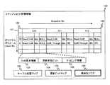
図3は、本発明の第1の実施の形態のスナップショット管理情報140の一例を示す図である。 FIG. 3 is a diagram illustrating an example of the
スナップショット管理情報140は、スナップショット管理テーブル150、テーブル配置マップ160、更新ビットマップ170及び格納先フラグ180を含む。 The
スナップショット管理テーブル150には、オリジナルデータ格納ボリューム210のchunkごとに、各スナップショットで実際に参照されるデータの格納位置などが格納される。 In the snapshot management table 150, for each chunk of the original
スナップショット管理テーブル150は、chunkNo152ごとに、SnapshotNo151によって特定される各スナップショットに対応する情報が格納される。スナップショットに対応する情報には、CoW(Copy On Write)要求情報153、更新状態ビット154及びマッピング情報155が含まれる。 The snapshot management table 150 stores information corresponding to each snapshot specified by the
CoW要求情報153は、対応するchunkに格納されたデータがオリジナルデータ格納ボリューム210に格納されているか、差分データ格納ボリューム220に格納されているかを示す情報である。対応するChunkに格納されたデータがオリジナルデータ格納ボリューム210に格納されている場合には「Need_CoW」が設定され、差分データ格納ボリューム220に格納されている場合には「CoW_Through」が設定される。 The
更新状態ビット154には、スナップショットの採取又は削除時に遅延更新処理が実行されている場合に、対応するchunkに格納されたデータが更新中であるか否かが格納される。更新中の場合には「Busy」が設定され、処理されていない場合には「Idle」が設定される。 The
マッピング情報155には、対応するchunkに格納されたデータが差分データ格納ボリューム220に格納されている場合に、差分データ格納ボリューム220のアドレス(chunkNo)が格納される。したがって、CoW要求情報153に「CoW_Through」が設定されている場合に値が設定される。なお、CoW要求情報153に「Need_CoW」が設定されている場合には、データが更新されていないため、オリジナルデータ格納ボリューム210に指定されたデータが参照され、マッピング情報155にはNULLが設定される。 The
テーブル配置マップ160は、スナップショット管理情報140が格納されている実LUのアドレスが格納される。スナップショット管理情報140は、システムの稼働中にはメモリ102に記憶されているが、システム停止時などには実LUに退避されているため、システム起動時などにはテーブル配置マップ160を参照し、スナップショット管理情報140をメモリ102に読み出す。 The
更新ビットマップ170は、スナップショット採取時にシステムがリブートされた場合などにデータの更新処理の整合性を保証するためにデータの更新状況を記録する。 The
格納先フラグ180は、ドメインから更新が要求されたデータの格納先を指定するフラグである。格納先フラグ180には、「オリジナルデータ」又は「差分データ」が設定される。格納先フラグ180に「オリジナルデータ」が設定されている場合にはオリジナルデータ格納ボリューム210に更新データが格納され、「差分データ」が設定されている場合には差分データ格納ボリューム220に更新データが格納される。本発明の第1の実施の形態では、格納先フラグ180を切り替えることによって、同じオリジナルデータ格納ボリューム210にポイントされた複数の更新可能なスナップショットに対し、個別に更新したり、一括して更新したりすることができる。 The
以上が本発明の第1の実施の形態の計算機システムの構成である。以下、本発明の第1の実施の形態の処理について詳細を説明する。まず、通常の更新処理について図4から図6を参照しながら説明する。 The above is the configuration of the computer system according to the first embodiment of this invention. Details of the processing according to the first embodiment of the present invention will be described below. First, normal update processing will be described with reference to FIGS.
図4は、本発明の第1の実施の形態のスナップショットに対する更新処理の手順を示すフローチャートである。 FIG. 4 is a flowchart illustrating a procedure of update processing for a snapshot according to the first embodiment of this invention.
NASヘッド100のCPU101は、ドメイン10AからVNAS120A(又はドメイン10BからVNAS120B)に対するデータの更新要求を受け付けると、更新要求に含まれる更新データの格納先領域(対象chunk)を取得するために、スナップショット管理テーブル対象chunk割り出し処理を実行する(S401)。スナップショット管理テーブル対象chunk割り出し処理の詳細については、図5にて後述する。 When the
NASヘッド100のCPU101は、S401のスナップショット管理テーブル対象chunk割り出し処理によって取得された対象chunkの情報を、ドメインから要求された処理に基づいて参照又は更新するために、スナップショット管理テーブル参照/更新処理を実行する(S402)。スナップショット管理テーブル参照/更新処理の詳細については、図6にて後述する。 The
最後に、NASヘッド100のCPU101は、S401及びS402の処理によって特定された対象chunkに更新データを書き込む(S403)。 Finally, the
図5は、本発明の第1の実施の形態のスナップショット管理テーブル対象chunk割り出し処理の手順を示すフローチャートである。 FIG. 5 is a flowchart illustrating a procedure of snapshot management table target chunk indexing processing according to the first embodiment of this invention.
スナップショット管理テーブル対象chunk割り出し処理は、ドメインから送信された更新要求に基づいて、オリジナルデータ格納ボリューム210における対象chunkを特定する。さらに、スナップショット管理テーブル150から対応する情報を取得する。以下、処理について具体的に説明する。 In the snapshot management table target chunk determination process, the target chunk in the original
NASヘッド100のCPU101は、NAS_OS110のLVM制御部125によって、ドメインから受信した更新要求に含まれる「宛先HLUN」、「宛先LBA」及び「ブロックサイズ」を取得する(S501)。宛先HLUNは、更新対象のデータが格納されるボリュームを識別するLUNである。宛先LBAは、宛先HLUNによって特定されたボリュームの論理アドレスである。ブロックサイズは、データが読み書きされるブロックのサイズである。 The
NASヘッド100のCPU101は、S501の処理で取得された宛先LBA及びブロックサイズに基づいて宛先chunkNoを算出する(S502)。宛先chunkNoは、更新対象のデータが格納される領域の識別情報である。具体的には、宛先chunkNoは、宛先LBA/ブロックサイズで算出される。 The
NASヘッド100のCPU101は、VNAS−HLUNマッピングテーブル130を参照し、更新要求を受け付けた仮想NASの識別情報がVNASID131に一致するレコードのテーブル種別132から対応するLUの種類を取得する(S503)。 The
なお、更新要求を受け付けた仮想NASに対応するLUが実LUの場合、又は、格納先フラグ180が「オリジナルデータ」の場合には、S502の処理で算出された宛先chunkNoに基づいて、更新データを格納すればよい。一方、更新要求を受け付けた仮想NASに対応するLUが仮想LUであって、かつ、格納先フラグ180が「差分データ」の場合には、スナップショット管理テーブル150を参照し、更新データを実際に格納する領域を特定する必要がある。 If the LU corresponding to the virtual NAS that received the update request is a real LU, or if the
NASヘッド100のCPU101は、VNAS−HLUNマッピングテーブル130を参照し、更新要求を受け付けた仮想NASの識別情報に基づいて、対応するスナップショットの識別情報(SnapshotNo135)を取得する(S504)。 The
さらに、NASヘッド100のCPU101は、S502の処理で取得された宛先chunkNoとS504の処理で取得されたSnapshotNo135に基づいて、スナップショット管理テーブル150から対応する情報を取得する(S505)。 Further, the
図6は、本発明の第1の実施の形態のスナップショット管理テーブル参照/更新処理の手順を示すフローチャートである。 FIG. 6 is a flowchart illustrating a procedure of snapshot management table reference / update processing according to the first embodiment of this invention.
スナップショット管理テーブル参照/更新処理では、更新データの格納先が更新中の場合には更新が完了するまで待機し、さらに、仮想LUに更新データを格納する場合には格納先である差分データ格納ボリューム220のchunkを特定する。 In the snapshot management table reference / update process, if the update data storage destination is being updated, the process waits until the update is completed. Further, if the update data is stored in the virtual LU, the difference data storage that is the storage destination is stored. The chunk of the
NASヘッド100のCPU101は、スナップショット管理テーブル対象chunk割り出し処理で取得された対象chunkの更新状態ビット154の値が「Busy」か否かを判定する(S601)。更新状態ビット154の値が「Busy」の場合には(S601の結果が「Yes」)、更新が終了するまで待機する(S602)。 The
NASヘッド100のCPU101は、次に、対象の仮想NASに対応するLUが仮想LU、かつ、格納先フラグが「差分データ」であるか否かを判定する(S603)。すなわち、更新データの格納先が差分データ格納ボリューム220であるか否かを判定する。更新先が差分データ格納ボリューム220でない場合には(S603の結果が「No」)、スナップショット管理テーブル対象chunk割り出し処理で取得された対象chunkに格納されているデータを更新すればよいため、本処理を終了する。 Next, the
NASヘッド100のCPU101は、更新先が差分データ格納ボリューム220である場合には(S603の結果が「Yes」)、CoW要求情報153を参照し、対象chunkが更新されたことがあるか否かを判定する(S604)。なお、対象chunkが更新されたことがある場合には、更新データが差分データ格納ボリューム220に格納されているため、CoW要求情報153に「CoW_Through」が設定されている。一方、対象chunkが更新されたことがない場合には、オリジナルデータ格納ボリューム210に格納されたデータを参照するため、CoW要求情報153に「Need_CoW」が設定されている。 When the update destination is the differential data storage volume 220 (the result of S603 is “Yes”), the
NASヘッド100のCPU101は、対象chunkが更新されたことがある場合には(S604の結果が「Yes」)、マッピング情報155を参照し、差分データ格納ボリューム220のchunkを識別するchunkNoを取得する(S605)。一方、対象chunkが更新されたことがない場合には(S604の結果が「No」)、差分データ格納ボリューム220に新たに更新データを格納するための領域を特定し、当該領域に対応するchunkNoをマッピング情報155に書き込む(S606)。このとき、CoW要求情報153の値を「Need_CoW」から「CoW_Through」に更新する。 If the target chunk has been updated (the result of S604 is “Yes”), the
スナップショット管理テーブル参照/更新処理が終了すると、NASヘッド100のCPU101は、図4のS403の処理で、以上の処理によって特定されたchunkに更新データを書き込み、本処理を終了する。 When the snapshot management table reference / update process ends, the
以上説明した更新処理は、格納先フラグ180がユーザによってあらかじめ設定され、更新が要求されたスナップショットに仮想LUが割り当てられている場合に、設定された格納先フラグ180の値に基づいてデータが更新される。すなわち、ユーザが更新する内容などに応じて更新データを格納する領域を随時切り替える。例えば、複数の環境で利用されているシステムにおいて、マスタ情報など共通して利用される情報を更新する場合に利用される。各システムで個別に更新及び追加される情報については、仮想NASごとに割り当てられた差分データ格納ボリューム220の領域に格納される。 In the update processing described above, when the
さらに、本発明の第1の実施の形態の計算機システムで提供されている仮想NASごとに実行されているVNAS_OSをバージョンアップする場合について説明する。前述のように、VNAS_OSのコマンドファイルなどは各仮想NASで共通に利用することが可能であるため、オリジナルデータ格納ボリューム210に格納される。一方、ログファイルなどは仮想NASごとに保持される情報であるため、差分データ格納ボリューム220に格納される。 Furthermore, a case will be described in which the version of VNAS_OS executed for each virtual NAS provided in the computer system according to the first embodiment of this invention is upgraded. As described above, the VNAS_OS command file and the like can be shared by each virtual NAS, and are stored in the original
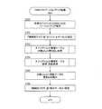
図7は、本発明の第1の実施の形態のVNAS_OSを更新するための手順を示すフローチャートである。 FIG. 7 is a flowchart illustrating a procedure for updating the VNAS_OS according to the first embodiment of this invention.
NASヘッド100のCPU101は、任意のドメインからVNAS_OSのバージョンアップ要求を受け付ける(S701)。計算機システムに管理端末が含まれている場合には、管理端末からVNAS_OSのバージョンアップ要求を受け付けるようにしてもよい。ここでは、NASヘッド100によって提供されているすべての仮想NASについて、VNAS_OSをバージョンアップする。また、VNAS_OSのバージョンアップ要求の受け付け時にVNAS_OSのバージョンアップに必要な更新データは既にNASヘッド100に受け付けられているものとする。 The
NASヘッド100のCPU101は、VNAS_OSのバージョンアップ要求を受け付けると、格納先フラグ180を「オリジナルデータ」に設定する(S702)。前述のように、格納先フラグ180を「オリジナルデータ」に設定することによって、各VNAS_OSを構成するファイルの更新対象を差分データ格納ボリューム220からオリジナルデータ格納ボリューム210に切り替えることができる。 Upon receiving the VNAS_OS version upgrade request, the
NASヘッド100のCPU101は、スナップショット管理テーブル対象chunk割り出し処理を実行し(S703)、更新データを格納する対象chunkを特定する。なお、スナップショット管理テーブル対象chunk割り出し処理は、図5にて説明した手順と同様である。 The
NASヘッド100のCPU101は、スナップショット管理テーブル参照/更新処理を実行する(S704)。なお、スナップショット管理テーブル参照/更新処理は、図6にて説明した手順と同様である。 The
NASヘッド100のCPU101は、スナップショット管理テーブル対象chunk割り出し処理で特定された対象chunkに更新データを書き込む(S705)。更新データの書き込みが終了すると、格納先フラグ180を「差分データ」に設定し(S706)、更新データの格納先を差分データ格納ボリューム220に切り替える。 The
このようにVNAS_OSのバージョンアップの際に、VNAS_OSを構成するファイルの格納先について、格納先フラグを「オリジナルデータ」に切り替えることによって、各仮想NASのOSのバージョンアップを同時に行うことができる。また、各仮想NASで設定された設定ファイル及びログファイルなどは、差分データ格納ボリューム220にそのまま保持されているため、カスタマイズされた環境などを維持することができる。 As described above, when the version of the VNAS_OS is upgraded, the OS of each virtual NAS can be upgraded at the same time by switching the storage destination flag to “original data” for the storage destination of the files constituting the VNAS_OS. In addition, since the setting file and log file set in each virtual NAS are held in the differential
さらに、本発明の第1の実施の形態のNASヘッド100において、仮想NASを追加する手順及び稼働中の仮想NASのOSをバージョンアップする手順を、画面例を参照しながら説明する。まず、画面例を説明する前に、共通のオリジナルデータ格納ボリューム210を利用する仮想NASの集合である仮想NASグループについて説明する。 Furthermore, in the
図8は、本発明の第1の実施の形態の仮想NASグループを説明する図である。 FIG. 8 is a diagram illustrating the virtual NAS group according to the first embodiment of this invention.
本発明の第1の実施の形態では、仮想NASごとにVNAS_OSが稼働している。このとき、VNAS_OSを稼働させるために必要なファイルのうち、コマンドファイルのように、各仮想NASで共通して利用可能なファイルをオリジナルデータ格納ボリューム210に格納する。また、ログファイルのように、各仮想NASで保持されるデータを差分データ格納ボリューム220に格納する。このように、同じオリジナルデータ格納ボリューム210に格納された構成ファイルによってVNAS_OSが稼働している仮想NASを「仮想NASグループ」とする。 In the first embodiment of the present invention, the VNAS_OS is operating for each virtual NAS. At this time, among files necessary for operating the VNAS_OS, a file that can be commonly used by each virtual NAS, such as a command file, is stored in the original
本発明の第1の実施の形態では、1つの仮想NASグループにオリジナルデータ格納ボリューム210及び差分データ格納ボリューム220が一つずつ対応するように構成されている。また、差分データ格納ボリューム220に各仮想NAS固有のデータが格納されているが、仮想NASごとに差分データ格納ボリューム220を有するように構成してもよい。また、1つの仮想NASグループに複数のオリジナルデータ格納ボリューム210を対応させてもよい。 In the first embodiment of the present invention, the original
続いて、NASヘッド100に仮想NASの追加を要求する手順について、画面例を参照しながら説明する。 Next, a procedure for requesting the
図9は、本発明の第1の実施の形態の仮想NASを追加するための仮想NAS追加画面900の一例を示す図である。 FIG. 9 is a diagram illustrating an example of a virtual
図9に示す仮想NAS追加画面900では、単体の仮想NASを追加する機能と、仮想NASグループを追加する機能を実行することができる。 In the virtual
単体の仮想NASを追加する場合には、まず、仮想NAS追加(単体)910を選択し、さらに、入力欄911などに必要な情報を入力する。 In the case of adding a single virtual NAS, first, a virtual NAS addition (single) 910 is selected, and further necessary information is input in the
一方、仮想NASグループを新たに生成、又は既存の仮想NASグループに新たに仮想NASを追加する場合には、まず、仮想NAS追加(グループ)920を選択する。そして、仮想NASグループの新規作成、又は仮想NASグループリスト921から追加する仮想NASグループを選択する。 On the other hand, when a new virtual NAS group is created or a new virtual NAS is added to an existing virtual NAS group, a virtual NAS addition (group) 920 is first selected. Then, a new virtual NAS group is created or a virtual NAS group to be added is selected from the virtual
既存の仮想NASグループを選択した場合には、選択された仮想NASグループに対応するオリジナルデータ格納ボリューム210と差分データ格納ボリューム220を新たに追加された仮想NASに割り当てる。 When an existing virtual NAS group is selected, the original
仮想NASグループを新規作成する場合には、LU選択欄930からオリジナルデータ格納ボリューム210に対応するLUと、差分データ格納ボリューム220に対応するLUとを選択する。オリジナルデータ格納ボリューム210に対応するLUを選択する場合には、オリジナルデータ格納ボリューム追加ボタン931を操作する。また、差分データ格納ボリューム220に対応するLUを選択する場合には差分データ格納ボリューム追加ボタン932を操作する。選択されたオリジナルデータ格納ボリューム及び差分データ格納ボリュームは、選択済みLUリスト934に追加される。また、選択されたLUを解除する場合には、選択済みLUリスト934に含まれているLUを選択し、LU削除ボタン933を操作する。 When a new virtual NAS group is created, an LU corresponding to the original
すべての必要な項目の入力を完了し、OKボタン935を操作すると、仮想NASグループ確認画面が表示される。なお、仮想NAS追加グループ確認画面の詳細については、図10にて後述する。 When input of all necessary items is completed and the
新たに仮想NASが追加される仮想NASグループの内容が確認されると、仮想NASの追加処理が実行され、仮想NASグループ追加完了通知画面が表示される。なお、仮想NASグループ追加完了通知画面の詳細については、図11にて後述する。 When the contents of a virtual NAS group to which a virtual NAS is newly added are confirmed, a virtual NAS addition process is executed, and a virtual NAS group addition completion notification screen is displayed. Details of the virtual NAS group addition completion notification screen will be described later with reference to FIG.
図10は、本発明の第1の実施の形態の仮想NAS追加グループ確認画面の一例を示す図である。 FIG. 10 is a diagram illustrating an example of the virtual NAS addition group confirmation screen according to the first embodiment of this invention.
仮想NAS追加グループ確認画面には、仮想NASが追加された仮想NASグループに含まれる仮想NASの一覧と、当該仮想NASグループに割り当てられたオリジナルデータ格納ボリューム210及び差分データ格納ボリューム220に対応するLUの識別情報が表示される。 The virtual NAS addition group confirmation screen displays a list of virtual NAS included in the virtual NAS group to which the virtual NAS is added, and LUs corresponding to the original
管理者は、表示された内容が正しければ、「OK」ボタンを操作し、内容を変更する必要がある場合には、「Cancel」ボタンを操作する。「OK」ボタンが操作されると、前述のように、仮想NASの追加処理が実行される。 If the displayed content is correct, the administrator operates the “OK” button. If the content needs to be changed, the administrator operates the “Cancel” button. When the “OK” button is operated, the virtual NAS addition processing is executed as described above.
図11は、本発明の第1の実施の形態の仮想NASグループ追加完了通知画面の一例を示す図である。 FIG. 11 is a diagram illustrating an example of a virtual NAS group addition completion notification screen according to the first embodiment of this invention.
前述のように、仮想NAS追加グループ確認画面の「OK」ボタンが操作されると、仮想NASの追加処理が実行される。仮想NASグループ追加完了通知画面は、仮想NASの追加処理が完了したことを通知するために表示される。 As described above, when the “OK” button on the virtual NAS addition group confirmation screen is operated, the virtual NAS addition processing is executed. The virtual NAS group addition completion notification screen is displayed to notify the completion of the virtual NAS addition processing.
さらに、仮想NASのOSをバージョンアップする手順について説明する。ここでは、特に仮想NASグループに属するすべての仮想NASのOSをバージョンアップする場合について説明する。 Furthermore, a procedure for upgrading the OS of the virtual NAS will be described. Here, a case will be described in which the OSs of all virtual NAS belonging to the virtual NAS group are upgraded.
図12は、本発明の第1の実施の形態の仮想NASのOSを管理する仮想NAS_OS管理画面1200の一例を示す図である。 FIG. 12 is a diagram illustrating an example of the virtual
仮想NAS_OS管理画面1200では、OSに関連するファイル(プログラム)を新たにインストールしたり、インストール済みのファイルをアンインストールしたりする機能を有する。さらに、インストール済みのファイルをバージョンアップする機能を有する。 The virtual
仮想NAS_OS管理画面1200には、インストール済みプログラムリスト1201及びインストール可能プログラムリスト1203が含まれている。 The virtual
インストール済みプログラムリスト1201には、仮想NASにインストール済みのプログラムが格納されている。インストール済みプログラムリスト1201に示されているファイルは処理を実行するためのプログラムであって、設定ファイルなどは、プログラムのインストール後、仮想NASごとの設定画面(別画面)で作成又は設定される。 The installed
なお、インストール済みのファイルは、ファイル選択後、アンインストールボタン1202を操作することによって削除することが可能である。 The installed file can be deleted by operating the
インストール可能プログラムリスト1203には、仮想NASに新たにインストール可能なファイルの一覧が表示される。インストール可能プログラムリスト1203に表示されたファイルは、インストール済みプログラムよりもバージョンが新しいファイル、又はインストールされていないプログラムのファイルなどである。 The
インストールモード1204には、既存の仮想NASにファイルをインストールする更新モードと、新たに追加された仮想NASにOSをインストールする新規インストールとがある。図7に示した仮想NASのOSバージョンアップ処理を実行する場合には、更新インストールが選択される。 The
バージョンアップモード1205には、指定された仮想NASが属する仮想NASグループに含まれるすべての仮想NASに対してファイルをインストールするグループモードと、指定された仮想NASに対してのみファイルをインストールする単体モードとがある。本発明の第1の実施の形態における図7に示した仮想NASのOSバージョンアップ処理を実行する場合には、グループモードが選択される。 The
単体モードでは、インストールされるファイルが差分データ格納ボリューム220に格納される。一方、グループモードでは、オリジナルデータ格納ボリューム210に格納されることで、指定された仮想NASが属する仮想NASグループに含まれるすべての仮想NASに対してファイルをインストール(バージョンアップ)することができる。 In the single mode, the file to be installed is stored in the differential
仮想NAS_OS管理画面1200に設定が必要な項目に値を入力した後、OKボタン1206が操作されると、インストール対象の仮想NASの確認画面が表示される。なお、確認画面の詳細については、図13にて後述する。 When a value is entered for an item that needs to be set on the virtual
さらに、インストール対象の仮想NASの確認画面で、インストール対象の仮想NASが確認されると、ファイルのインストールが開始され、インストールの完了後、完了通知画面が表示される。なお、完了通知画面の詳細については、図14にて後述する。 Furthermore, when the installation target virtual NAS is confirmed on the installation target virtual NAS confirmation screen, the installation of the file is started, and after the installation is completed, a completion notification screen is displayed. Details of the completion notification screen will be described later with reference to FIG.
図13は、本発明の第1の実施の形態の仮想NASのOSのバージョンアップ時の確認画面の一例を示す図である。 FIG. 13 is a diagram illustrating an example of a confirmation screen when upgrading the OS of the virtual NAS according to the first embodiment of this invention.
インストール確認画面には、グループモードの場合には、インストール対象の仮想NASが追加された仮想NASグループに含まれる仮想NASの一覧と、当該仮想NASグループに割り当てられたオリジナルデータ格納ボリューム210及び差分データ格納ボリューム220に対応するLUの識別情報が表示される。一方、単体モードの場合には、仮想NAS名のみが表示される。 In the group confirmation mode, in the group mode, the list of virtual NAS included in the virtual NAS group to which the virtual NAS to be installed is added, the original
管理者は、表示された内容が正しければ、「OK」ボタンを操作し、内容を変更する必要がある場合には、「Cancel」ボタンを操作する。「OK」ボタンが操作されると、ファイルのインストールが開始される。具体的は、図7に示した仮想NASのOSバージョンアップ処理が実行される。 If the displayed content is correct, the administrator operates the “OK” button. If the content needs to be changed, the administrator operates the “Cancel” button. When the “OK” button is operated, file installation is started. Specifically, the OS upgrade process of the virtual NAS shown in FIG. 7 is executed.
図14は、本発明の第1の実施の形態の仮想NASのOSのバージョンアップの完了を通知する画面の一例を示す図である。 FIG. 14 is a diagram illustrating an example of a screen for notifying completion of version upgrade of the virtual NAS OS according to the first embodiment of this invention.
前述のように、インストール確認画面の「OK」ボタンが操作されると、選択されたファイルのインストールが実行される。インストール完了通知画面は、ファイルのインストールが完了したことを通知するために表示される。 As described above, when the “OK” button on the installation confirmation screen is operated, the selected file is installed. The installation completion notification screen is displayed to notify that the file installation is completed.
以上が、複数の仮想NASでそれぞれ稼働しているVNAS_OSを一括してバージョンアップする手順である。 The above is the procedure for upgrading the version of the VNAS_OS running on each of the plurality of virtual NASs.
なお、仮想NASのOSをバージョンアップする例を、図12などを参照しながら説明したが、例えば、ファイルを保存する際に、格納先フラグ180を切り替えるための画面を表示するなどして、個別にファイルの格納先を切り替えるようにしてもよい。また、格納先フラグ180を切り替えるための画面は、ファイルの保存するための画面に格納先フラグ180を切り替えるチェックボックスを追加することでも実現することが可能である。NASヘッド100は、更新データの格納先の切り替え指示を受け付けると、要求に応じて格納先フラグ180を設定する。このように、ドメインからの要求に応じて格納先フラグ180を設定することも可能である。 An example of upgrading the virtual NAS OS has been described with reference to FIG. 12 and the like. For example, when saving a file, a screen for switching the
さらに、本発明の第1の実施の形態では、NASヘッド100とストレージ装置200とが分離された構成となっていたが、NASヘッド100とストレージ装置200とが一体のNASであっても、本発明を適用するとは可能である。この場合、仮想NASとHLUNとの対応を格納するVNAS−HLUNマッピングテーブル130の代わりに、仮想NASとボリューム(LUN)との対応を管理するテーブルを利用すればよい。 Furthermore, in the first embodiment of the present invention, the
本発明の第1の実施の形態によれば、複数の仮想NASに対して一括してデータを更新するか、仮想NASごとに個別にデータを更新するかを、利用者によって容易に切り替えることができる。したがって、すべての仮想NASで共有されているデータを仮想NASごとに更新せずに一括してデータを更新することができる。 According to the first embodiment of this invention, the user can easily switch between updating data for a plurality of virtual NAS at once or updating data individually for each virtual NAS. it can. Therefore, it is possible to update the data in a batch without updating the data shared by all the virtual NASs for each virtual NAS.
さらに、仮想NASごとに個別に更新データを格納する場合には仮想NASごとに更新データを保持する必要があるが、本発明の第1の実施の形態によれば、共有するボリュームに格納されたデータを更新することによって、更新データを保持するために必要な記憶容量を少なくすることができる。 Furthermore, when update data is stored individually for each virtual NAS, it is necessary to hold the update data for each virtual NAS. According to the first embodiment of the present invention, the update data is stored in the shared volume. By updating the data, the storage capacity required to hold the updated data can be reduced.
本発明の第1の実施の形態によれば、共有されているデータを更新した差分はそのまま保持されているため、更新前に変更された内容を仮想NASごとにそのまま保持することができる。 According to the first embodiment of the present invention, since the difference obtained by updating the shared data is held as it is, the contents changed before the update can be held as they are for each virtual NAS.
本発明の第1の実施の形態によれば、OSを一括してバージョンアップすることが可能であるため、OSのバージョンアップに要する時間を削減することができ、運用コストを低減させることができる。また、前述のように、オリジナルデータから変更された差分データは、そのまま保持されているため、カスタマイズされた環境設定などをそのまま継承することができる。 According to the first embodiment of the present invention, it is possible to upgrade OSs in a batch, so that it is possible to reduce the time required for OS upgrades and to reduce operational costs. . Further, as described above, since the difference data changed from the original data is held as it is, customized environment settings and the like can be inherited as they are.
(第2の実施の形態)
本発明の第1の実施の形態では、NASヘッド100が更新データの格納先を切り替えていたが、第2の実施の形態では、ストレージ装置200が単体で更新データの格納先を切り替える。(Second Embodiment)
In the first embodiment of the present invention, the
なお、第2の実施の形態において、第1の実施の形態と共通する内容については適宜説明を省略する。 Note that in the second embodiment, description of the contents common to the first embodiment will be omitted as appropriate.
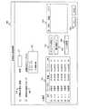
図15は、本発明の第2の実施の形態の計算機システムの構成を示す図である。 FIG. 15 is a diagram illustrating a configuration of a computer system according to the second embodiment of this invention.
本発明の第2の実施の形態の計算機システムには、第1の実施の形態と同様に、NASヘッド100及びストレージ装置200が含まれている。 The computer system according to the second embodiment of this invention includes a
本発明の第2の実施の形態では、前述のように、ストレージ装置200が単体で更新データの格納先を切り替える機能を有する。したがって、VNAS−HLUNマッピングテーブル130及びスナップショット管理情報140をNASヘッド100に必要としないため、従来技術によって実装されたNASヘッドを利用することができる。 In the second embodiment of the present invention, as described above, the
一方、ストレージ装置200には、更新データの格納先を切り替えるために必要なHLUN−LUNマッピングテーブル230及びスナップショット管理情報240が備えられる。また、ストレージ装置200には、更新可能なスナップショットを提供する機能を有している。なお、その他の構成については、第1の実施の形態と同様である。 On the other hand, the
HLUN−LUNマッピングテーブル230は、ストレージ装置200のFCI/F204に対応するHLUNとオリジナルデータ格納ボリューム210及び差分データ格納ボリューム220とを対応付ける。HLUN−LUNマッピングテーブル230の詳細については、図17にて後述する。 The HLUN-LUN mapping table 230 associates the HLUN corresponding to the FCI / F 204 of the
スナップショット管理情報240の構成は、第1の実施の形態のスナップショット管理情報140と同じである。 The configuration of the
図16は、本発明の第2の実施の形態のHLUN−LUNマッピングテーブル230の一例を示す図である。 FIG. 16 is a diagram illustrating an example of the HLUN-LUN mapping table 230 according to the second embodiment of this invention.
HLUN−LUNマッピングテーブル230には、前述のように、HLUNとオリジナルデータ格納ボリューム210及び差分データ格納ボリューム220との対応が格納される。なお、仮想NASとHLUNとの関係については、NASヘッド100に記憶されるが、一般的な仮想NASの実装に必要な情報である。 The HLUN-LUN mapping table 230 stores the correspondence between the HLUN and the original
HLUN−LUNマッピングテーブル230は、HLUNID231、テーブル種別132、オリジナルデータ格納ボリュームLUN233、差分データ格納ボリュームLUN234及びSnapshotNo235を含む。 The HLUN-LUN mapping table 230 includes an
HLUNID231は、NASヘッド100によって認識されるホストLUNを一意に識別する識別子である。 The
テーブル種別232は、第1の実施の形態のテーブル種別132と同様に、HLUNID231に対応するスナップショットが仮想LUに割り当てられているか、実LUに割り当てられているかを示す情報である。仮想LUの場合には「VertialLU」、実LUの場合には「PhysicalLU」が設定される。 The
オリジナルデータ格納ボリュームLUN233は、オリジナルデータ格納ボリューム210を識別するLUNである。差分データ格納ボリュームLUN234には、差分データ格納ボリューム220を識別するLUNである。 The original data
SnapshotNo135は、HLUNID231によって識別されるHLUNに対応するスナップショットの識別子である。 Snapshot No 135 is an identifier of a snapshot corresponding to the HLUN identified by the
図17は、本発明の第2の実施の形態のスナップショット管理テーブル対象chunk割り出し処理の手順を示すフローチャートである。 FIG. 17 is a flowchart illustrating a procedure of snapshot management table target chunk indexing processing according to the second embodiment of this invention.
スナップショット管理テーブル対象chunk割り出し処理は、NASヘッド100から受信したWriteコマンドに含まれる情報に基づいて、対象chunkを特定する。基本的には、第1の実施の形態の図5に示した手順と同じである。以下、具体的に処理について説明する。 In the snapshot management table target chunk determination process, the target chunk is specified based on information included in the Write command received from the
ストレージ装置200のマイクロプロセッサ201は、NASヘッド100からWriteコマンドを受信すると、受信したWriteコマンドに含まれる「宛先HLUN」、「宛先LBA」及び「ブロックサイズ」を取得する(S1701)。「宛先HLUN」、「宛先LBA」及び「ブロックサイズ」については、第1の実施の形態と同様である。 When receiving the Write command from the
ストレージ装置200のマイクロプロセッサ201は、S1701の処理で取得された宛先LBA及びブロックサイズに基づいて宛先chunkNoを算出する(S1702)。算出方法については、第1の実施の形態と同様である。 The
ストレージ装置200のマイクロプロセッサ201は、HLUN−LUNマッピングテーブル230を参照し、更新要求を受け付けたHLUNの識別情報がHLUNID231に一致するレコードのテーブル種別232から対応するLUの種類を取得する(S1703)。 The
ストレージ装置200のマイクロプロセッサ201は、HLUN−LUNマッピングテーブル230を参照し、更新要求を受け付けた仮想NASの識別情報に基づいて、対応するスナップショットの識別情報(SnapshotNo235)を取得する(S1704)。 The
さらに、ストレージ装置200のマイクロプロセッサ201は、S1702の処理で取得された宛先chunkNoとS1704の処理で取得されたSnapshotNo235の値に基づいて、スナップショット管理テーブル150から対応するレコードを取得する(S1705)。 Furthermore, the
なお、仮想NASのOSをバージョンアップする手順についても、動作主体がNASヘッド100のCPU101からストレージ装置200のマイクロプロセッサ201に変更されるが、基本的な処理手順は第1の実施の形態と同様である。 The procedure for upgrading the virtual NAS OS is also changed from the
本発明の第2の実施の形態によれば、仮想NASを提供する機能を有するNASヘッド100と、本発明の第2の実施の形態のストレージ装置200とを組み合わせることによって、本発明の第1の実施の形態と同様の効果を得ることができる。 According to the second embodiment of the present invention, by combining the
さらに、本発明の第2の実施の形態では、ストレージ装置200に更新データの格納先を切り替える機能が備えられている。したがって、ストレージ装置200にスナップショットを提供する機能を有していれば、NASヘッド100を必要とせずに、本発明の効果を享受することができる。 Furthermore, in the second embodiment of the present invention, the
100 NASヘッド
101 CPU
102 メモリ
110 NAS_OS
125 LVM制御部
130 VNAS−HLUNマッピングテーブル
140 スナップショット管理情報
150 スナップショット管理テーブル
160 テーブル配置マップ
170 更新ビットマップ
180 格納先フラグ
200 ストレージ装置
201 マイクロプロセッサ
202 メモリ
210 オリジナルデータ格納ボリューム
220 差分データ格納ボリューム
230 HLUN−LUNマッピングテーブル
240 スナップショット管理情報100
102
125
Claims (14)
Translated fromJapanese前記計算機は、前記ストレージ装置に接続される第1のインターフェースと、前記第1のインターフェースに接続される第1のプロセッサと、前記第1のプロセッサに接続される第1のメモリと、を備え、
前記ストレージ装置は、前記計算機に接続される第2のインターフェースと、前記第2のインターフェースに接続される第2のプロセッサと、前記第2のプロセッサに接続される第2のメモリと、を備え、
前記ストレージ装置は、前記各記憶領域に共有されるデータを格納する第1のボリュームと、前記各記憶領域で保持されるデータを格納する第2のボリュームとを前記計算機に提供し、
前記第1のメモリには、前記各記憶領域を管理する記憶領域管理情報と、前記データの更新を受け付けた場合に更新データの格納先を設定する格納先フラグとが記憶され、
前記第1のプロセッサは、
前記データの格納先の指定を受け付けると、前記指定された格納先に基づいて、前記格納先フラグを設定し、
前記第1のボリュームに格納されたデータの更新を受け付け、かつ、前記格納先フラグが前記第1のボリュームに設定されている場合には、前記第1のボリュームの更新対象である第1の領域を特定し、前記特定された第1の領域を更新し、
前記第1のボリュームに格納されたデータの更新を受け付け、かつ、前記格納先フラグが前記第2のボリュームに設定されている場合には、前記記憶領域管理情報に基づいて、前記第1の領域に対応する第2の領域が前記第2のボリュームに割り当てられているか否かを判定し、
前記第2のボリュームに前記第2の領域が割り当てられている場合には、前記第2の領域を更新し、
前記第2のボリュームに前記第2の領域が割り当てられていない場合には、前記第2のボリュームに前記第2の領域を新たに割り当て、前記新たに割り当てられた第2の領域を更新し、
前記新たに割り当てられた第2の領域の位置情報を前記第1の領域に対応させて前記記憶領域管理情報に格納することを特徴とする計算機システム。A computer system including a computer that provides a plurality of storage areas for reading and writing data, and a storage device that stores data to be read and written to the storage areas,
The computer includes a first interface connected to the storage device, a first processor connected to the first interface, and a first memory connected to the first processor,
The storage device includes a second interface connected to the computer, a second processor connected to the second interface, and a second memory connected to the second processor,
The storage device provides the computer with a first volume for storing data shared by the storage areas and a second volume for storing data held by the storage areas,
The first memory stores storage area management information for managing each storage area, and a storage destination flag for setting a storage destination of update data when the update of the data is accepted,
The first processor is
Upon receiving designation of the storage location of the data, the storage location flag is set based on the designated storage location,
When the update of the data stored in the first volume is received and the storage destination flag is set in the first volume, the first area that is the update target of the first volume , Update the identified first region,
When the update of the data stored in the first volume is accepted and the storage destination flag is set in the second volume, the first area is based on the storage area management information. Whether or not the second area corresponding to is assigned to the second volume,
If the second area is assigned to the second volume, update the second area;
If the second area is not assigned to the second volume, the second area is newly assigned to the second volume, the newly assigned second area is updated,
A computer system characterized in that position information of the newly allocated second area is stored in the storage area management information in association with the first area.
前記第1のボリュームに格納されたデータの読み出しを受け付けた場合には、前記読み出し対象のデータを格納する第3の領域を特定し、
前記記憶領域管理情報に基づいて、前記第3の領域に対応する第4の領域が前記第2のボリュームに割り当てられているか否かを判定し、
前記第2のボリュームに前記第4の領域が割り当てられている場合には、前記第4の領域に格納されたデータを提供することを特徴とする請求項1に記載の計算機システム。The first processor is
When the reading of the data stored in the first volume is accepted, the third area for storing the data to be read is specified,
Determining whether a fourth area corresponding to the third area is allocated to the second volume based on the storage area management information;
2. The computer system according to claim 1, wherein, when the fourth area is allocated to the second volume, data stored in the fourth area is provided. 3.
前記第1のプロセッサは、前記記憶領域ごとに前記オペレーティングシステムを実行することを特徴とする請求項1に記載の計算機システム。The computer includes an operating system including a controller and a file system that manage the storage areas.
The computer system according to claim 1, wherein the first processor executes the operating system for each storage area.
前記第1のプロセッサは、前記格納先フラグを前記第1のボリュームに設定し、前記オペレーティングシステムを一括して更新することを特徴とする請求項4に記載の計算機システム。A file for executing the operating system is stored in the first volume and the second volume,
5. The computer system according to claim 4, wherein the first processor sets the storage destination flag to the first volume and updates the operating system collectively.
インターフェースと、前記インターフェースに接続されるプロセッサと、前記プロセッサに接続されるメモリと、を備え、
前記各記憶領域に共有されるデータを格納する第1のボリュームと、前記各記憶領域で保持されるデータを格納する第2のボリュームとを提供し、
前記メモリには、前記各記憶領域を管理する記憶領域管理情報と、前記データの更新を受け付けた場合に更新データの格納先を設定する格納先フラグとが記憶され、
前記プロセッサは、
前記データの格納先の指定を受け付けると、前記指定された格納先に基づいて、前記格納先フラグを設定し、
前記第1のボリュームに格納されたデータの更新を受け付け、かつ、前記格納先フラグが前記第1のボリュームに設定されている場合には、前記第1のボリュームの更新対象である第1の領域を特定し、前記特定された第1の領域を更新し、
前記第1のボリュームに格納されたデータの更新を受け付け、かつ、前記格納先フラグが前記第2のボリュームに設定されている場合には、前記記憶領域管理情報に基づいて、前記第1の領域に対応する第2の領域が前記第2のボリュームに割り当てられているか否かを判定し、
前記第2のボリュームに前記第2の領域が割り当てられている場合には、前記第2の領域を更新し、
前記第2のボリュームに前記第2の領域が割り当てられていない場合には、前記第2のボリュームに前記第2の領域を新たに割り当て、前記新たに割り当てられた第2の領域を更新し、
前記新たに割り当てられた第2の領域の位置情報を前記第1の領域に対応させて前記記憶領域管理情報に格納することを特徴とするストレージ装置。A storage device that provides a plurality of storage areas for reading and writing data,
An interface, a processor connected to the interface, and a memory connected to the processor,
Providing a first volume for storing data shared in each storage area, and a second volume for storing data held in each storage area;
The memory stores storage area management information for managing each storage area, and a storage destination flag for setting a storage destination of update data when an update of the data is received,
The processor is
Upon receiving designation of the storage location of the data, the storage location flag is set based on the designated storage location,
When the update of the data stored in the first volume is received and the storage destination flag is set in the first volume, the first area that is the update target of the first volume , Update the identified first region,
When the update of the data stored in the first volume is accepted and the storage destination flag is set in the second volume, the first area is based on the storage area management information. Whether or not the second area corresponding to is assigned to the second volume,
If the second area is assigned to the second volume, update the second area;
If the second area is not assigned to the second volume, the second area is newly assigned to the second volume, the newly assigned second area is updated,
The storage apparatus, wherein the location information of the newly allocated second area is stored in the storage area management information in association with the first area.
前記第1のボリュームに格納されたデータの読み出しを受け付けた場合には、前記読み出し対象のデータを格納する第3の領域を特定し、
前記記憶領域管理情報に基づいて、前記第3の領域に対応する第4の領域が前記第2のボリュームに割り当てられているか否かを判定し、
前記第2のボリュームに前記第4の領域が割り当てられている場合には、前記第4の領域に格納されたデータを提供することを特徴とする請求項6に記載のストレージ装置。The processor is
When the reading of the data stored in the first volume is accepted, the third area for storing the data to be read is specified,
Determining whether a fourth area corresponding to the third area is allocated to the second volume based on the storage area management information;
The storage apparatus according to claim 6, wherein when the fourth area is allocated to the second volume, data stored in the fourth area is provided.
前記プロセッサは、前記記憶領域ごとに前記オペレーティングシステムを実行することを特徴とする請求項6に記載のストレージ装置。The storage apparatus includes an operating system including a controller and a file system that manage the storage areas.
The storage apparatus according to claim 6, wherein the processor executes the operating system for each storage area.
前記プロセッサは、前記格納先フラグを前記第1のボリュームに設定し、前記オペレーティングシステムを一括して更新することを特徴とする請求項9に記載のストレージ装置。A file for executing the operating system is stored in the first volume and the second volume,
The storage apparatus according to claim 9, wherein the processor sets the storage destination flag in the first volume and updates the operating system collectively.
前記計算機は、前記ストレージ装置に接続される第1のインターフェースと、前記第1のインターフェースに接続される第1のプロセッサと、前記第1のプロセッサに接続される第1のメモリと、を備え、
前記ストレージ装置は、前記計算機に接続される第2のインターフェースと、前記第2のインターフェースに接続される第2のプロセッサと、前記第2のプロセッサに接続される第2のメモリと、を備え、
前記ストレージ装置は、前記各記憶領域に共有されるデータを格納する第1のボリュームと、前記各記憶領域で保持されるデータを格納する第2のボリュームとを前記計算機に提供し、
前記第1のメモリには、前記各記憶領域を管理する記憶領域管理情報と、前記データの更新を受け付けた場合に更新データの格納先を設定する格納先フラグとが記憶され、
前記方法は、
前記第1のプロセッサが、前記データの格納先の指定を受け付けると、前記指定された格納先に基づいて、前記格納先フラグを設定し、
前記第1のプロセッサが、前記第1のボリュームに格納されたデータの更新を受け付け、かつ、前記格納先フラグが前記第1のボリュームに設定されている場合には、前記第1のボリュームの更新対象である第1の領域を特定し、前記特定された第1の領域を更新し、
前記第1のプロセッサが、前記第1のボリュームに格納されたデータの更新を受け付け、かつ、前記格納先フラグが前記第2のボリュームに設定されている場合には、前記記憶領域管理情報に基づいて、前記第1の領域に対応する第2の領域が前記第2のボリュームに割り当てられているか否かを判定し、
前記第1のプロセッサが、前記第2のボリュームに前記第2の領域が割り当てられている場合には、前記第2の領域を更新し、
前記第1のプロセッサが、前記第2のボリュームに前記第2の領域が割り当てられていない場合には、前記第2のボリュームに前記第2の領域を新たに割り当て、前記新たに割り当てられた第2の領域を更新し、
前記第1のプロセッサが、前記新たに割り当てられた第2の領域の位置情報を前記第1の領域に対応させて前記記憶領域管理情報に格納することを特徴とするデータ更新方法。A data update method in a computer system, comprising: a computer that provides a plurality of storage areas for reading and writing data; and a storage device that stores data to be read and written to the storage areas,
The computer includes a first interface connected to the storage device, a first processor connected to the first interface, and a first memory connected to the first processor,
The storage device includes a second interface connected to the computer, a second processor connected to the second interface, and a second memory connected to the second processor,
The storage device provides the computer with a first volume for storing data shared by the storage areas and a second volume for storing data held by the storage areas,
The first memory stores storage area management information for managing each storage area, and a storage destination flag for setting a storage destination of update data when the update of the data is accepted,
The method
When the first processor accepts designation of the storage location of the data, the storage location flag is set based on the designated storage location,
When the first processor receives an update of data stored in the first volume and the storage destination flag is set in the first volume, the update of the first volume is performed. Identifying a first region of interest, updating the identified first region;
When the first processor accepts an update of data stored in the first volume and the storage destination flag is set in the second volume, it is based on the storage area management information. Determining whether a second area corresponding to the first area is allocated to the second volume;
The first processor updates the second area when the second area is allocated to the second volume;
If the second area is not allocated to the second volume, the first processor newly allocates the second area to the second volume, and the newly allocated second Update area 2
The data update method, wherein the first processor stores position information of the newly allocated second area in the storage area management information in association with the first area.
前記第1のプロセッサが、前記第1のボリュームに格納されたデータの読み出しを受け付けた場合には、前記読み出し対象のデータを格納する第3の領域を特定し、
前記第1のプロセッサが、前記記憶領域管理情報に基づいて、前記第3の領域に対応する第4の領域が前記第2のボリュームに割り当てられているか否かを判定し、
前記第1のプロセッサが、前記第2のボリュームに前記第4の領域が割り当てられている場合には、前記第4の領域に格納されたデータを提供することを特徴とする請求項11に記載のデータ更新方法。The method
When the first processor accepts reading of data stored in the first volume, it specifies a third area for storing the data to be read;
The first processor determines whether or not a fourth area corresponding to the third area is allocated to the second volume based on the storage area management information;
12. The data stored in the fourth area is provided by the first processor when the fourth area is allocated to the second volume. Data update method.
前記第1のボリューム及び前記第2のボリュームには、前記オペレーティングシステムを実行するためのファイルが格納され、
前記方法は、前記第1のプロセッサが、前記格納先フラグを前記第1のボリュームに設定し、前記オペレーティングシステムを一括して更新することを特徴とする請求項11に記載のデータ更新方法。The computer includes an operating system including a controller and a file system for managing each storage area, and the operating system is executed for each storage area,
A file for executing the operating system is stored in the first volume and the second volume,
12. The data updating method according to claim 11, wherein the first processor sets the storage destination flag in the first volume and updates the operating system collectively.
Priority Applications (3)
| Application Number | Priority Date | Filing Date | Title |
|---|---|---|---|
| JP2008272846AJP2010102479A (en) | 2008-10-23 | 2008-10-23 | Computer system, storage device, and data updating method |
| US12/344,688US8015219B2 (en) | 2008-10-23 | 2008-12-29 | Computer system storage device and date updating method |
| US13/220,732US20120060154A1 (en) | 2008-10-23 | 2011-08-30 | Computer system, storage device and date updating method |
Applications Claiming Priority (1)
| Application Number | Priority Date | Filing Date | Title |
|---|---|---|---|
| JP2008272846AJP2010102479A (en) | 2008-10-23 | 2008-10-23 | Computer system, storage device, and data updating method |
Publications (1)
| Publication Number | Publication Date |
|---|---|
| JP2010102479Atrue JP2010102479A (en) | 2010-05-06 |
Family
ID=42118478
Family Applications (1)
| Application Number | Title | Priority Date | Filing Date |
|---|---|---|---|
| JP2008272846APendingJP2010102479A (en) | 2008-10-23 | 2008-10-23 | Computer system, storage device, and data updating method |
Country Status (2)
| Country | Link |
|---|---|
| US (2) | US8015219B2 (en) |
| JP (1) | JP2010102479A (en) |
Cited By (9)
| Publication number | Priority date | Publication date | Assignee | Title |
|---|---|---|---|---|
| WO2011136089A1 (en) | 2010-04-27 | 2011-11-03 | 日本電気株式会社 | Coding device, error-correction code configuration method, and program thereof |
| WO2012035576A1 (en) | 2010-09-14 | 2012-03-22 | Hitachi, Ltd. | Storage system storing electronic modules applied to electronic objects common to several computers, and storage control method for the same |
| WO2012147119A1 (en) | 2011-04-25 | 2012-11-01 | Hitachi, Ltd. | Management system and control method for provisioning storage space to writable snapshots satisfying performance requirements |
| WO2013121465A1 (en) | 2012-02-16 | 2013-08-22 | Hitachi, Ltd. | Storage system, management server, storage apparatus, and data management method |
| WO2013140460A1 (en) | 2012-03-23 | 2013-09-26 | Hitachi, Ltd. | Patch applying method for virtual machine by cloning an operating system image on shared storage and applying a patch to this cloned image |
| JP2013210704A (en)* | 2012-03-30 | 2013-10-10 | Nec Corp | Data duplication system, data duplication method, and program therefor |
| WO2014115276A1 (en)* | 2013-01-24 | 2014-07-31 | 株式会社日立製作所 | Environmental setting server, computer system, and environmental setting method |
| US9671966B2 (en) | 2014-03-27 | 2017-06-06 | Hitachi, Ltd. | Management computer and computer system |
| JP2018530817A (en)* | 2015-09-10 | 2018-10-18 | ベリタス テクノロジーズ エルエルシー | Optimize access to production data |
Families Citing this family (8)
| Publication number | Priority date | Publication date | Assignee | Title |
|---|---|---|---|---|
| US20080306784A1 (en)* | 2007-06-05 | 2008-12-11 | Vijay Rajkumar | Computer-implemented methods and systems for analyzing clauses of contracts and other business documents |
| CN101359301A (en)* | 2008-08-19 | 2009-02-04 | 成都市华为赛门铁克科技有限公司 | Auto snapshot method and device |
| US9158828B1 (en)* | 2011-12-19 | 2015-10-13 | Emc Corporation | Techniques using associated object properties |
| US8843716B2 (en)* | 2012-04-24 | 2014-09-23 | Hitachi, Ltd. | Computer system, storage apparatus and data transfer method |
| WO2017078707A1 (en)* | 2015-11-04 | 2017-05-11 | Hitachi, Ltd. | Method and apparatus for recovering in-memory data processing system |
| US20170357388A1 (en)* | 2016-06-10 | 2017-12-14 | Apple Inc. | Device, Method, and Graphical User Interface for Managing Data Stored at a Storage Location |
| CN111190549A (en)* | 2019-12-30 | 2020-05-22 | 浪潮电子信息产业股份有限公司 | A method, device, device and medium for obtaining available capacity of a shared volume |
| CN113382308B (en)* | 2021-05-31 | 2022-11-22 | 北京达佳互联信息技术有限公司 | Information display method and device, electronic equipment and computer readable storage medium |
Family Cites Families (16)
| Publication number | Priority date | Publication date | Assignee | Title |
|---|---|---|---|---|
| US5197130A (en)* | 1989-12-29 | 1993-03-23 | Supercomputer Systems Limited Partnership | Cluster architecture for a highly parallel scalar/vector multiprocessor system |
| US6260120B1 (en)* | 1998-06-29 | 2001-07-10 | Emc Corporation | Storage mapping and partitioning among multiple host processors in the presence of login state changes and host controller replacement |
| US6421711B1 (en)* | 1998-06-29 | 2002-07-16 | Emc Corporation | Virtual ports for data transferring of a data storage system |
| JP2000276404A (en)* | 1999-03-29 | 2000-10-06 | Nec Corp | Method and device for virtual storage and recording medium |
| WO2002065275A1 (en)* | 2001-01-11 | 2002-08-22 | Yottayotta, Inc. | Storage virtualization system and methods |
| WO2003075166A1 (en)* | 2002-03-06 | 2003-09-12 | Fujitsu Limited | Storage system and data transfer method in the system |
| US6857001B2 (en) | 2002-06-07 | 2005-02-15 | Network Appliance, Inc. | Multiple concurrent active file systems |
| US7266654B2 (en)* | 2003-03-18 | 2007-09-04 | Hitachi, Ltd. | Storage system, server apparatus, and method for creating a plurality of snapshots |
| JP2005301708A (en)* | 2004-04-13 | 2005-10-27 | Hitachi Ltd | Software management method and storage device system in storage device system |
| JP2006011541A (en)* | 2004-06-22 | 2006-01-12 | Hitachi Ltd | Information recording method in computer system including computer and shared storage device |
| US7284019B2 (en)* | 2004-08-18 | 2007-10-16 | International Business Machines Corporation | Apparatus, system, and method for differential backup using snapshot on-write data |
| JP2008009485A (en)* | 2006-06-27 | 2008-01-17 | Fujitsu Ltd | Virtual storage control device and virtual storage control program |
| US8656386B1 (en)* | 2007-03-13 | 2014-02-18 | Parallels IP Holdings GmbH | Method to share identical files in a common area for virtual machines having the same operating system version and using a copy on write to place a copy of the shared identical file in a private area of the corresponding virtual machine when a virtual machine attempts to modify the shared identical file |
| US8566502B2 (en)* | 2008-05-29 | 2013-10-22 | Vmware, Inc. | Offloading storage operations to storage hardware using a switch |
| US8689292B2 (en)* | 2008-04-21 | 2014-04-01 | Api Technologies Corp. | Method and systems for dynamically providing communities of interest on an end user workstation |
| US8046550B2 (en)* | 2008-07-14 | 2011-10-25 | Quest Software, Inc. | Systems and methods for performing backup operations of virtual machine files |
- 2008
- 2008-10-23JPJP2008272846Apatent/JP2010102479A/enactivePending
- 2008-12-29USUS12/344,688patent/US8015219B2/ennot_activeExpired - Fee Related
- 2011
- 2011-08-30USUS13/220,732patent/US20120060154A1/ennot_activeAbandoned
Cited By (17)
| Publication number | Priority date | Publication date | Assignee | Title |
|---|---|---|---|---|
| RU2527207C2 (en)* | 2010-04-27 | 2014-08-27 | Нек Корпорейшн | Coding device, error-correction code configuration method and programme therefor |
| WO2011136089A1 (en) | 2010-04-27 | 2011-11-03 | 日本電気株式会社 | Coding device, error-correction code configuration method, and program thereof |
| WO2012035576A1 (en) | 2010-09-14 | 2012-03-22 | Hitachi, Ltd. | Storage system storing electronic modules applied to electronic objects common to several computers, and storage control method for the same |
| US8566541B2 (en) | 2010-09-14 | 2013-10-22 | Hitachi, Ltd. | Storage system storing electronic modules applied to electronic objects common to several computers, and storage control method for the same |
| WO2012147119A1 (en) | 2011-04-25 | 2012-11-01 | Hitachi, Ltd. | Management system and control method for provisioning storage space to writable snapshots satisfying performance requirements |
| US9170749B2 (en) | 2011-04-25 | 2015-10-27 | Hitachi, Ltd. | Management system and control method for computer system for managing a storage apparatus |
| WO2013121465A1 (en) | 2012-02-16 | 2013-08-22 | Hitachi, Ltd. | Storage system, management server, storage apparatus, and data management method |
| US9026753B2 (en) | 2012-02-16 | 2015-05-05 | Hitachi, Ltd. | Snapshot volume generational management for snapshot copy operations using differential data |
| WO2013140460A1 (en) | 2012-03-23 | 2013-09-26 | Hitachi, Ltd. | Patch applying method for virtual machine by cloning an operating system image on shared storage and applying a patch to this cloned image |
| US9069640B2 (en) | 2012-03-23 | 2015-06-30 | Hitachi, Ltd. | Patch applying method for virtual machine, storage system adopting patch applying method, and computer system |
| JP2013210704A (en)* | 2012-03-30 | 2013-10-10 | Nec Corp | Data duplication system, data duplication method, and program therefor |
| US9235349B2 (en) | 2012-03-30 | 2016-01-12 | Nec Corporation | Data duplication system, data duplication method, and program thereof |
| WO2014115276A1 (en)* | 2013-01-24 | 2014-07-31 | 株式会社日立製作所 | Environmental setting server, computer system, and environmental setting method |
| GB2525773A (en)* | 2013-01-24 | 2015-11-04 | Hitachi Ltd | Environmental setting server, computer system, and environmental setting method |
| JP6023221B2 (en)* | 2013-01-24 | 2016-11-09 | 株式会社日立製作所 | Environment setting server, computer system, and environment setting method |
| US9671966B2 (en) | 2014-03-27 | 2017-06-06 | Hitachi, Ltd. | Management computer and computer system |
| JP2018530817A (en)* | 2015-09-10 | 2018-10-18 | ベリタス テクノロジーズ エルエルシー | Optimize access to production data |
Also Published As
| Publication number | Publication date |
|---|---|
| US8015219B2 (en) | 2011-09-06 |
| US20120060154A1 (en) | 2012-03-08 |
| US20100106688A1 (en) | 2010-04-29 |
Similar Documents
| Publication | Publication Date | Title |
|---|---|---|
| JP2010102479A (en) | Computer system, storage device, and data updating method | |
| US9189344B2 (en) | Storage management system and storage management method with backup policy | |
| US7558916B2 (en) | Storage system, data processing method and storage apparatus | |
| US8448167B2 (en) | Storage system, and remote copy control method therefor | |
| US8443160B2 (en) | Computer system and data migration method | |
| US8122212B2 (en) | Method and apparatus for logical volume management for virtual machine environment | |
| JP5149556B2 (en) | Storage system that migrates system information elements | |
| JP4945363B2 (en) | Storage system connected at the back end | |
| US9069640B2 (en) | Patch applying method for virtual machine, storage system adopting patch applying method, and computer system | |
| US7860909B2 (en) | Search engine system using snapshot function of storage system | |
| US20070220071A1 (en) | Storage system, data migration method and server apparatus | |
| US20120260051A1 (en) | Computer system, management system and data management method | |
| US20200192693A1 (en) | Container provision support system and container provision support method | |
| US9170749B2 (en) | Management system and control method for computer system for managing a storage apparatus | |
| US7801822B2 (en) | Method of controlling storage system | |
| US10990373B2 (en) | Service managers and firmware version selections in distributed computing systems | |
| US20140337594A1 (en) | Systems and methods for collapsing a derivative version of a primary storage volume | |
| US7676644B2 (en) | Data processing system, storage apparatus and management console | |
| WO2018158808A1 (en) | Information system, management program, and program exchanging method for information system | |
| US20060059188A1 (en) | Operation environment associating data migration method | |
| US8117405B2 (en) | Storage control method for managing access environment enabling host to access data | |
| US20060221721A1 (en) | Computer system, storage device and computer software and data migration method | |
| JP6492863B2 (en) | Extended storage control device, extended storage control system, extended storage control method, and extended storage control program | |
| US20230281161A1 (en) | File storage system | |
| JP2002023959A (en) | Disk array controller |