JP2010098699A - Receiving apparatus, and control method thereof - Google Patents
Receiving apparatus, and control method thereofDownload PDFInfo
- Publication number
- JP2010098699A JP2010098699AJP2008270290AJP2008270290AJP2010098699AJP 2010098699 AJP2010098699 AJP 2010098699AJP 2008270290 AJP2008270290 AJP 2008270290AJP 2008270290 AJP2008270290 AJP 2008270290AJP 2010098699 AJP2010098699 AJP 2010098699A
- Authority
- JP
- Japan
- Prior art keywords
- connection
- unit
- transmission
- transmitting
- determination
- Prior art date
- Legal status (The legal status is an assumption and is not a legal conclusion. Google has not performed a legal analysis and makes no representation as to the accuracy of the status listed.)
- Pending
Links
Images


Classifications
- H—ELECTRICITY
- H04—ELECTRIC COMMUNICATION TECHNIQUE
- H04N—PICTORIAL COMMUNICATION, e.g. TELEVISION
- H04N5/00—Details of television systems
- H04N5/76—Television signal recording
- H04N5/765—Interface circuits between an apparatus for recording and another apparatus
- G—PHYSICS
- G09—EDUCATION; CRYPTOGRAPHY; DISPLAY; ADVERTISING; SEALS
- G09G—ARRANGEMENTS OR CIRCUITS FOR CONTROL OF INDICATING DEVICES USING STATIC MEANS TO PRESENT VARIABLE INFORMATION
- G09G5/00—Control arrangements or circuits for visual indicators common to cathode-ray tube indicators and other visual indicators
- G09G5/003—Details of a display terminal, the details relating to the control arrangement of the display terminal and to the interfaces thereto
- G09G5/006—Details of the interface to the display terminal
- G—PHYSICS
- G09—EDUCATION; CRYPTOGRAPHY; DISPLAY; ADVERTISING; SEALS
- G09G—ARRANGEMENTS OR CIRCUITS FOR CONTROL OF INDICATING DEVICES USING STATIC MEANS TO PRESENT VARIABLE INFORMATION
- G09G2330/00—Aspects of power supply; Aspects of display protection and defect management
- G09G2330/02—Details of power systems and of start or stop of display operation
- G09G2330/021—Power management, e.g. power saving
- G09G2330/022—Power management, e.g. power saving in absence of operation, e.g. no data being entered during a predetermined time
- G—PHYSICS
- G09—EDUCATION; CRYPTOGRAPHY; DISPLAY; ADVERTISING; SEALS
- G09G—ARRANGEMENTS OR CIRCUITS FOR CONTROL OF INDICATING DEVICES USING STATIC MEANS TO PRESENT VARIABLE INFORMATION
- G09G2370/00—Aspects of data communication
- G09G2370/12—Use of DVI or HDMI protocol in interfaces along the display data pipeline
- G—PHYSICS
- G09—EDUCATION; CRYPTOGRAPHY; DISPLAY; ADVERTISING; SEALS
- G09G—ARRANGEMENTS OR CIRCUITS FOR CONTROL OF INDICATING DEVICES USING STATIC MEANS TO PRESENT VARIABLE INFORMATION
- G09G5/00—Control arrangements or circuits for visual indicators common to cathode-ray tube indicators and other visual indicators
- G09G5/12—Synchronisation between the display unit and other units, e.g. other display units, video-disc players
- H—ELECTRICITY
- H04—ELECTRIC COMMUNICATION TECHNIQUE
- H04N—PICTORIAL COMMUNICATION, e.g. TELEVISION
- H04N5/00—Details of television systems
- H04N5/63—Generation or supply of power specially adapted for television receivers
Landscapes
- Engineering & Computer Science (AREA)
- Physics & Mathematics (AREA)
- Computer Hardware Design (AREA)
- General Physics & Mathematics (AREA)
- Theoretical Computer Science (AREA)
- Multimedia (AREA)
- Signal Processing (AREA)
- Two-Way Televisions, Distribution Of Moving Picture Or The Like (AREA)
Abstract
Translated fromJapaneseDescription
Translated fromJapanese本発明は、受信装置、及びその制御方法に関する。 The present invention relates to a receiving apparatus and a control method thereof.
近年、液晶パネル製造技術の進歩などにより、テレビ受信機の表示画面の高精細化が進んでいる。これに伴い、HDDレコーダなどの外部装置からテレビ受信機に対して送信されるビデオデータ及びオーディオデータも大容量化している。大容量のデータを送信するために、HDMI(High Definition Multimedia Interface)と呼ばれるインタフェースがしばしば使用される(非特許文献1)。また、複数のHDMIポートを備えるテレビ受信機も普及しつつある。HDMIは、ひとつのケーブルでビデオデータ及びオーディオデータを伝送することができるので、複数のケーブルを接続する煩わしさがなくなるという利点を有している。 In recent years, display screens of television receivers have become higher definition due to advances in liquid crystal panel manufacturing technology. Along with this, video data and audio data transmitted from an external device such as an HDD recorder to a television receiver are also increasing in capacity. In order to transmit a large amount of data, an interface called HDMI (High Definition Multimedia Interface) is often used (Non-Patent Document 1). Also, television receivers having a plurality of HDMI ports are becoming popular. Since HDMI can transmit video data and audio data with a single cable, it has the advantage of eliminating the hassle of connecting a plurality of cables.
HDMIはCEC(Consumer Electronics Control)ラインと呼ばれる通信線を有する。CECを使用すれば、受信装置(例えば、テレビ受信機)と送信装置(例えば、HDDレコーダ)とを連携して動作させることができる。例えば、受信装置は、電源オフをトリガにしてStandbyコマンドを送信装置に送信することにより、送信装置の電源もオフにすることができる。また、送信装置が再生開始をトリガにしてImageViewOnコマンドもしくはTextViewOnコマンドを受信装置に送信すると、受信装置の電源が投入される。そして、送信装置がActiveSourceコマンドを受信装置に送信し、受信装置がコマンド内に格納されている物理アドレスに従ってデータ入力元のHDMIポートの切り替えを行う。 HDMI has a communication line called a CEC (Consumer Electronics Control) line. If CEC is used, a receiving apparatus (for example, a television receiver) and a transmitting apparatus (for example, an HDD recorder) can be operated in cooperation. For example, the receiving apparatus can also turn off the power of the transmitting apparatus by transmitting a Standby command to the transmitting apparatus using the power-off as a trigger. In addition, when the transmission apparatus transmits an ImageViewOn command or a TextViewOn command to the reception apparatus with the start of reproduction as a trigger, the power of the reception apparatus is turned on. Then, the transmission device transmits an ActiveSource command to the reception device, and the reception device switches the data input source HDMI port according to the physical address stored in the command.
CEC通信は、送信装置が物理アドレス及び論理アドレスを取得した後に可能となる。物理アドレスの取得については、送信装置は、受信装置からのHPD(Hot Plug Detect)ラインが有効となると、DDC(Display Data Channel)ラインを使用して受信装置のEDID(Extended Display Identification Data)ロムを読み出すことにより行う。また、論理アドレスの取得については、送信装置は、CECコマンドにより取得したい論理アドレスの問い合せを行い、未使用であることを確認することにより行う。 CEC communication is possible after the transmission device acquires a physical address and a logical address. For acquisition of the physical address, when the HPD (Hot Plug Detect) line from the receiving device becomes valid, the transmitting device uses the DDC (Display Data Channel) line to obtain the EDID (Extended Display Identification Data) ROM of the receiving device. This is done by reading. In addition, the acquisition of the logical address is performed by the transmission apparatus inquiring the logical address to be acquired by the CEC command and confirming that it is not used.
しかしながら、送信装置によっては、EDID読み出し処理終了後にDDCラインを使用してHDCP(High-bandwidth Digital Content Protection)による認証が完了しないと物理アドレス及び論理アドレスの取得を完了できない。 However, depending on the transmission device, acquisition of a physical address and a logical address cannot be completed unless authentication by HDCP (High-bandwidth Digital Content Protection) using the DDC line is completed after completion of the EDID reading process.
一方、受信装置は、複数のHDMIポートを備えていても、ユーザが選択したHDMIポートに接続された装置に対してのみHDCP認証を行うのが一般的である。そのため、受信装置は送信装置とHDCP認証を行うポートについてのみHPDを有効にする。そのため、送信装置はHPDが無効になるたびに物理アドレス及び論理アドレスをクリアしてしまうと、CEC通信を行うことができない。 On the other hand, even if the receiving device includes a plurality of HDMI ports, it is common to perform HDCP authentication only for devices connected to the HDMI port selected by the user. Therefore, the receiving device validates HPD only for the port that performs HDCP authentication with the transmitting device. Therefore, the CEC communication cannot be performed if the transmission device clears the physical address and the logical address each time HPD becomes invalid.
そこで、特許文献1は、HPDの有効無効に関係なくCEC通信を継続することに関する技術を開示している。特許文献1によれば、HPDが無効となると、送信装置は以前に取得した物理アドレス及び論理アドレスを保持して使用することによりCEC通信を継続する。
しかしながら、特許文献1によれば、ユーザが送信装置をHPDが無効であるか又はHDCP認証ができないHDMIポートに接続した場合、送信装置は、以前に取得した物理アドレス及び論理アドレスを保持し続ける。その後ユーザが送信装置の再生ボタンを押下すると、ActiveSourceコマンド内の物理アドレスが以前に取得した値(即ち、現在の接続状態を正しく反映していない値)であるため、受信装置はデータの入力元を正しいポートに切り替えることができない。 However, according to
本発明はこのような状況に鑑みてなされたものであり、受信装置に接続された送信装置が誤ったアドレスを保持する可能性を低減する技術を提供することを目的とする。 The present invention has been made in view of such a situation, and an object of the present invention is to provide a technique for reducing the possibility that a transmission apparatus connected to a reception apparatus holds an incorrect address.
上記課題を解決するために、第1の本発明は、受信装置であって、ビデオデータ及びオーディオデータのうちの少なくとも一方を前記受信装置へ送信する複数の送信装置を、直接又は中継装置を介して接続するための複数の接続手段と、前記複数の接続手段のいずれかを選択する選択手段と、前記選択手段が選択している接続手段に接続された送信装置からアクセス可能であり、前記送信装置がビデオデータ及びオーディオデータのうちの少なくとも一方を前記受信装置に対して送信するために必要な認証情報を記憶している認証情報記憶手段と、前記複数の接続手段のいずれかに送信装置が接続されたことを検出する検出手段と、前記検出手段が送信装置の接続を検出した場合に、前記複数の接続手段それぞれについて、当該接続手段が前記選択手段により選択された場合に当該接続手段に接続された送信装置が前記認証情報を取得することが可能であるか不可能であるかを示す、当該接続手段から入力されるステータス信号が「不可能」から「可能」に変化したか否かを判定する判定手段と、前記判定手段による判定の結果、前記ステータス信号が「不可能」から「可能」に変化した接続手段が存在しなかった場合に、前記検出手段が検出した送信装置に対して電源をオンにするよう指示する電源オンコマンドを送信する送信手段であって、当該電源オンコマンドを送信した後に前記判定手段に再び前記判定を行わせる送信手段と、前記判定手段による判定の結果、前記ステータス信号が「不可能」から「可能」に変化した接続手段が存在した場合に、当該接続手段を選択するように前記選択手段を制御する制御手段と、を備えることを特徴とする受信装置を提供する。 In order to solve the above-described problem, a first aspect of the present invention is a receiving device, wherein a plurality of transmitting devices that transmit at least one of video data and audio data to the receiving device are directly or via a relay device. A plurality of connection means for connecting, a selection means for selecting one of the plurality of connection means, and a transmission device connected to the connection means selected by the selection means, and the transmission An authentication information storage unit storing authentication information necessary for the device to transmit at least one of video data and audio data to the receiving device, and a transmitting device in any of the plurality of connection units A detecting means for detecting that the connection is established; and when the detecting means detects the connection of the transmission device, for each of the plurality of connecting means, the connecting means When selected by the selection means, the status signal input from the connection means indicating whether or not the transmitting device connected to the connection means can acquire the authentication information is “not good”. When there is no connection means in which the status signal has changed from “impossible” to “possible” as a result of the determination by the determination means and the determination means that determines whether or not the state has changed from “possible” And a transmission means for transmitting a power-on command for instructing the transmission device detected by the detection means to turn on the power, and after the power-on command is transmitted, the determination means performs the determination again. And when the status signal has changed from "impossible" to "possible" as a result of the determination by the determination means, the connection means is selected. And control means for controlling the urchin said selection means, to provide a receiving apparatus, characterized in that it comprises a.
また、第2の本発明は、受信装置の制御方法であって、当該受信装置は、ビデオデータ及びオーディオデータのうちの少なくとも一方を前記受信装置へ送信する複数の送信装置を、直接又は中継装置を介して接続するための複数の接続手段と、前記複数の接続手段のいずれかを選択する選択手段と、前記選択手段が選択している接続手段に接続された送信装置からアクセス可能であり、前記送信装置がビデオデータ及びオーディオデータのうちの少なくとも一方を前記受信装置に対して送信するために必要な認証情報を記憶している認証情報記憶手段と、を備え、前記制御方法は、前記複数の接続手段のいずれかに送信装置が接続されたことを検出する検出工程と、前記検出工程で送信装置の接続が検出された場合に、前記複数の接続手段それぞれについて、当該接続手段が前記選択手段により選択された場合に当該接続手段に接続された送信装置が前記認証情報を取得することが可能であるか不可能であるかを示す、当該接続手段から入力されるステータス信号が「不可能」から「可能」に変化したか否かを判定する判定工程と、前記判定工程における判定の結果、前記ステータス信号が「不可能」から「可能」に変化した接続手段が存在しなかった場合に、前記検出工程で検出された送信装置に対して電源をオンにするよう指示する電源オンコマンドを送信する送信工程であって、当該電源オンコマンドを送信した後に前記判定工程に再び前記判定を行わせる送信工程と、前記判定工程における判定の結果、前記ステータス信号が「不可能」から「可能」に変化した接続手段が存在した場合に、当該接続手段を選択するように前記選択手段を制御する制御工程と、を備えることを特徴とする制御方法を提供する。 The second aspect of the present invention is a control method for a receiving device, wherein the receiving device directly or relays a plurality of transmitting devices that transmit at least one of video data and audio data to the receiving device. A plurality of connection means for connecting via the connection means, a selection means for selecting any one of the plurality of connection means, and a transmission device connected to the connection means selected by the selection means, is accessible, Authentication information storage means for storing authentication information necessary for the transmission device to transmit at least one of video data and audio data to the reception device, and the control method includes the plurality of the control methods. A detecting step for detecting that the transmitting device is connected to any one of the connecting means, and when the connecting of the transmitting device is detected in the detecting step, the plurality of connecting means For each, the connection means indicating whether or not the transmitting device connected to the connection means can acquire the authentication information when the connection means is selected by the selection means Determination process for determining whether the status signal input from “impossible” has changed to “possible”, and as a result of the determination in the determination process, the status signal has changed from “impossible” to “possible” A transmission step of transmitting a power-on command instructing the transmission device detected in the detection step to turn on the power when the connection means does not exist, wherein the power-on command is transmitted A transmission step that causes the determination step to perform the determination again later, and a connection means in which the status signal has changed from “impossible” to “possible” as a result of the determination in the determination step; When Mashimashi provides control method characterized by and a control step of controlling the selection means to select the connection means.
なお、その他の本発明の特徴は、添付図面及び以下の発明を実施するための最良の形態における記載によって更に明らかになるものである。 Other features of the present invention will become more apparent from the accompanying drawings and the following description of the best mode for carrying out the invention.
以上の構成により、本発明によれば、受信装置に接続された送信装置が誤ったアドレスを保持する可能性を低減することが可能となる。 With the above configuration, according to the present invention, it is possible to reduce the possibility that the transmission device connected to the reception device holds an incorrect address.
以下、添付図面を参照して、本発明の実施例を説明する。以下で説明される個別の実施例は、本発明の上位概念から下位概念までの種々の概念を理解するために役立つであろう。 Embodiments of the present invention will be described below with reference to the accompanying drawings. The individual embodiments described below will help to understand various concepts from the superordinate concept to the subordinate concept of the present invention.
なお、本発明の技術的範囲は、特許請求の範囲によって確定されるのであって、以下の個別の実施例によって限定されるわけではない。また、実施例の中で説明されている特徴の組み合わせすべてが、本発明に必須とは限らない。 The technical scope of the present invention is determined by the scope of the claims, and is not limited by the following individual embodiments. In addition, all combinations of features described in the embodiments are not necessarily essential to the present invention.
図1は、実施例1に係る受信装置100の構成を示すブロック図である。受信装置100は、例えばテレビ受信機であるが、HDMI(High Definition Multimedia Interface)のシンクとして動作できる装置であればどのようなものでも構わない。 FIG. 1 is a block diagram illustrating the configuration of the
受信装置100は、2つのHDMIポート(HDMIポート103及びHDMIポート104)を備え、HDMIインタフェースによってそれぞれに送信装置101、送信装置102が接続されている。送信装置101及び送信装置102は、例えばHDDレコーダであるが、HDMIのソースとして動作してビデオデータ及びオーディオデータのうちの少なくとも一方を受信装置100に送信できる装置であればどのようなものでも構わない。受信装置100は、2つより多くのHDMIポートを備えていてもよい。 The
受信装置100はまた、HDCP(High-bandwidth Digital Content Protection)による認証を行うための認証情報を格納したHDCPロム109(認証情報記憶手段)を備える。 The
受信装置100はまた、データを受信するHDMIレシーバ108と、HDMIポート103及びHDMIポート104のうちのいずれからのデータをHDMIレシーバ108に入力するかを選択するHDMIセレクタ107とを備える。HDCPロム109は、HDMIセレクタ107が選択しているHDMIポートに接続された送信装置からアクセス可能である。また、HDMIセレクタ107が選択しているHDMIポートに接続されていても電源がオフの場合はHDCPロム109から認証情報を取得できないように構成された送信装置も存在する。 The
受信装置100はまた、HDMIレシーバ108が受信したビデオデータの画像を表示する表示部110と、オーディオデータの音声を出力する音声出力部111とを備える。但し、表示部110及び音声出力部111は受信装置100に必ずしも含まれる必要はない。 The
受信装置100はまた、受信装置100の各種情報(表示部110の解像度や各HDMIポートに接続される送信装置に付与する物理アドレス等)が書き込まれたEDIDロム105及び106を備え、各々がHDMIポート103及び104に接続されている。例えば、HDMIポート103に接続される送信装置に付与する物理アドレスは”1.0.0.0”であり、HDMIポート104に接続される送信装置に付与する物理アドレスは”2.0.0.0”である。 The
受信装置100はまた、接続された送信装置に正しいアドレスを取得させるように動作する制御部112を備える(動作の詳細は後述する)。制御部112は、HDMIセレクタ107にセレクタ切替信号を送信することによりHDMIセレクタ107の切り替えを制御するHDMIセレクタ切替部113を有する。制御部112はまた、5VPWR検出部114と、HPD制御部115と、CEC制御部116とを有し、それぞれがHDMIポート103及び104に接続されている。HPD制御部115は、HDMIセレクタ107によって選択されたHDMIポートのHPD信号をアクティブにする。これにより、選択されたHDMIポートに接続された送信装置がHDCP認証を行うことが可能になる。 The
但し、前述の通り、電源がオフの場合はHDCPロム109から認証情報を取得できないように構成された送信装置も存在する。制御部112は、5VPWR検出部114に入力される信号(ステータス信号)を調べることにより、HDMIポート103及び104それぞれに接続された送信装置が認証情報を取得することが可能であるか不可能であるかを知ることができる。例えば、送信装置101の電源がオンの場合や、電源がオフであっても認証情報を取得可能なように送信装置101が構成されている場合は、HDMIポート103から5VPWR検出部114に、「可能」を示すステータス信号が入力される。 However, as described above, there is also a transmission device configured such that authentication information cannot be acquired from the
次に、図2を参照して、CEC制御部116の構成を説明する。 Next, the configuration of the
CEC制御部116は、CEC信号を受信するCEC受信部300と、CEC信号(CECコマンド)を送信するCEC送信部304とを備える。CEC制御部116はまた、Report_Physical_Addressコマンドを受信してこのコマンドが示す論理アドレスに対応する物理アドレスを検出する物理アドレス検出部301を備える。CEC制御部116はまた、PingコマンドのACKビットを検出することにより、このPingコマンドが示す論理アドレスを有する送信装置の接続を検出する論理アドレス検出部302を備える。CEC制御部116はまた、Report_Power_Statusコマンドを受信してこのコマンドが示す論理アドレスを持つ送信装置の電源状態を検出する電源状態検出部303を備える。CEC制御部116はまた、CECコマンド(電源オンコマンド、電源オフコマンド、接続確認コマンドなど)を生成するコマンド生成部305と、受信装置100に接続された送信装置の状態を管理する接続装置管理部306とを備える。 The
CEC受信部300は、物理アドレス検出部301、論理アドレス検出部302、及び電源状態検出部303と接続されており、送信装置から受信したコマンドを解釈して適切な検出部にコマンドを転送する。物理アドレス検出部301、論理アドレス検出部302、及び電源状態検出部303は、検出した内容を通知するために、接続装置管理部306に接続されている。 The
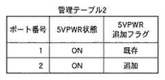
接続装置管理部306は、図3に示す管理テーブル1、及び図4に示す管理テーブル2を保持する。管理テーブル1は、「論理アドレス」「論理アドレス追加フラグ」「物理アドレス」「電源オンコマンド送信フラグ」という項目を有する。管理テーブル2は、「5VPWR状態」「5VPWR追加フラグ」という項目を有する。 The connection
管理テーブル1の「論理アドレス」は、受信装置100に接続されている送信装置の論理アドレスを示し、「論理アドレス追加フラグ」は、各論理アドレスを持つ送信装置が新規に追加されたものであるか或いは既存のものであるかを示す。「物理アドレス」は、各論理アドレスに対応した送信装置の物理アドレスを示し、「電源オンコマンド送信フラグ」は、各論理アドレスを持つ送信装置に対して電源オンコマンドを送信したか否かを示す。従って、接続装置管理部306は管理テーブル1の「電源オンコマンド送信フラグ」を有することにより、装置情報記憶手段としても機能する。 The “logical address” in the management table 1 indicates the logical address of the transmitting device connected to the receiving
管理テーブル2の「5VPWR状態」は、受信装置100が備える各HDMIポートに接続された送信装置の5VPWRの状態を示し、「5VPWR追加フラグ」は、各HDMIポートに対して5VPWRが追加されたのか否かを示す。 “5VPWR state” in the management table 2 indicates the state of 5VPWR of the transmission device connected to each HDMI port included in the
接続装置管理部306は、「5VPWR状態」の更新を行うために、5VPWR検出部114と接続されている(図1参照)。また、接続装置管理部306は、CECコマンドを生成して送信するために、コマンド生成部305と接続され、コマンド生成部305は、CEC送信部304と接続され、CEC送信部304は、HDMIポート103及び104と接続されている。 The connection
次に、図5を参照して、HDMIセレクタ切替部113の構成を説明する。 Next, the configuration of the HDMI
HDMIセレクタ切替部113は、時間を計測するタイマ部400と、どのHDMIポートを入力元に選択するかを5VPWR状態に基づいて判定する切替判定部401と、HDMIセレクタ107を切り替える切替制御部402とを備える。タイマ部400は接続装置管理部306と接続され、ここからタイマクリア信号を受信する。切替判定部401は、接続装置管理部306と接続され、ここから入力切替要求信号を受信する。切替判定部401はまた、タイマ部400と接続され、ここへタイマスタート要求信号を送信すると共にここからタイムアウト信号を受信する。切替制御部402はHDMIセレクタ107と接続され、ここへHDMIセレクト信号を送信する。 The HDMI
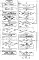
次に、図6を参照して、実施例1に従って受信装置100が送信装置にアドレスを取得させる処理を説明する。本フローチャートの各ステップの処理は、特に断らない限り、CEC制御部116が不図示のROMに格納された制御プログラムを実行することにより実現される(以下の他のフローチャートにおいても同様)。 Next, with reference to FIG. 6, the process in which the receiving
S1で、コマンド生成部305は、所定の間隔(例えば、1秒毎)にPingコマンドを生成してCEC送信部304から出力することにより、受信装置100に接続された送信装置に対してPingコマンドを送信する。Pingコマンドは、接続をチェックしたい論理アドレスの数だけ生成して送信される。論理アドレス検出部302は、返ってきたPingコマンドの最終ビットであるACKビットの電圧レベルをチェックする。電圧レベルがHighであればPingコマンドが示す論理アドレスを有する送信装置は接続されておらず、Lowであれば接続されているということを示す。これにより、論理アドレス検出部302は、CEC機能を備える送信装置101及び102が新たに接続(追加)されたり切断されたりしたことが検出される。論理アドレスの追加又は削除(即ち、送信装置の接続又は切断)が検出されると、S2に進む。 In S <b> 1, the
論理アドレスが削除された場合はS2からS3へ進み、接続装置管理部306は、管理テーブル1(図3参照)から削除された論理アドレスの行を削除し、S1に戻る。 When the logical address is deleted, the process proceeds from S2 to S3, and the connection
論理アドレスが追加された場合はS2からS4を経由してS5へ進み、接続装置管理部306は、管理テーブル1に追加された論理アドレスの行を追加する。このとき、「論理アドレス追加フラグ」には「追加」という値が入力される。次いでS6に進む。 When the logical address is added, the process proceeds from S2 to S5 via S4, and the connection
S6で、接続装置管理部306は、5VPWR検出部114を用いてHDMIポート103及び104それぞれの5VPWRの状態を検出し、状態に変化があった場合は管理テーブル2(図4参照)の「5VPWR状態」を更新する。また、5VPWRがアサートされた場合(OFFからONに変化した場合)は、接続装置管理部306は、管理テーブル2の「5VPWR追加フラグ」に「追加」という値を入力する。 In S6, the connection
S7で、接続装置管理部306は、管理テーブル2の「5VPWR追加フラグ」が「追加」となっているHDMIポートが存在するか否かを判定する。判定の結果、存在しない場合はS8に進み、存在する場合はS11に進む。管理テーブル2の「5VPWR追加フラグ」が「追加」となっているということは、5VPWR検出部114に入力されるステータス信号が「不可能」から「可能」に変化したということを意味する。 In step S <b> 7, the connection
ところで、論理アドレスが追加されたにも関わらず5VPWRの状態に変化が無いということは、追加された送信装置の電源がOFFであり、認証情報を取得できないためにアドレスを更新できないということを意味する。そこで、以下に説明するようにS8乃至S10で追加された送信装置の電源をONにする処理が行われる。一方、追加された送信装置の電源がOFFであっても5VPWRがアサートされた場合は、この送信装置はアドレスを更新できるので、電源をONにせずにS11に進む。なお、図示しないが、S7における判定及びその後の各処理は、追加された論理アドレス毎に実行される。 By the way, the fact that there is no change in the state of 5VPWR despite the addition of the logical address means that the address cannot be updated because the power of the added transmitter is OFF and authentication information cannot be acquired. To do. Therefore, as described below, processing for turning on the power of the transmission apparatus added in S8 to S10 is performed. On the other hand, if 5VPWR is asserted even if the power supply of the added transmission apparatus is OFF, the transmission apparatus can update the address, and the process proceeds to S11 without turning on the power supply. Although not shown, the determination in S7 and the subsequent processes are executed for each added logical address.
S8で、コマンド生成部305は、Give_Device_Power_Statusコマンド(電源オンコマンド)を生成し、追加された論理アドレスを持つ送信装置に対して送信する。これに対する応答として電源状態検出部303はReport_Power_Statusコマンドを受信する。これにより、電源状態検出部303は、この送信装置の電源状態を確認する。電源がONであればS9を経由してS6に戻る(S6で管理テーブル2が更新され、次はS7からS11へと進む)。電源がOFFであればS9からS10へと進む。 In S8, the
S10で、コマンド生成部305は、User_Control_Press(Power On)コマンドを生成して送信装置へ送信する。この時、接続装置管理部306は、User_Control_Press(Power On)コマンドの送信先の論理アドレスについて、管理テーブル1の「電源オンコマンド送信フラグ」を「追加」に変更する。次いでS8に戻り、電源状態検出部303は送信装置の電源状態を再度確認する。 In step S10, the
S11で、接続装置管理部306は、入力切替要求信号を切替判定部401に送信する。切替判定部401は、切替制御部402に切替要求を送信する。切替要求を受信した切替制御部402は、HDMIセレクタ107にセレクタ切替信号を送信する。これにより、入力元のHDMIポートが5VPWRが「追加」であるHDMIポート(即ち、ステータス信号が「不可能」から「可能」に変化したHDMIポート)に切り替えられる。また、HPD制御部115は、選択されたHDMIポートのHPD信号をアクティブにする。これにより、選択されたHDMIポートに接続されている送信装置がHDCP認証を行うことが可能になる。 In S <b> 11, the connection
S12で、切替判定部401は、タイマ部400にタイマスタート信号を送信する。タイマスタート信号を受信したタイマ部400はタイマをスタートする。 In S <b> 12, the switching
S13で、物理アドレス検出部301は、物理アドレスの更新に成功した送信装置が送信したReport_Physical_Addressコマンドを受信するか、或いはタイマ部400がタイムアウトするまで待つ。Report_Physical_Addressコマンドを受信した場合、接続装置管理部306は、この送信装置の論理アドレスに関して、管理テーブル1の「物理アドレス」にコマンドが示すアドレスを格納し、「論理アドレス追加フラグ」を「既存」に変更する。なお、図示しないが、タイムアウトした場合はタイマ部400がその旨をCEC制御部116に通知する。 In S <b> 13, the physical
S14で、接続装置管理部306は、タイマ部400にタイマクリア信号を送信し、タイマ部400はタイマをクリアする。 In S14, the connection
S15で、接続装置管理部306は、S13で受信した物理アドレスに対応する論理アドレスに関して管理テーブル1の「電源オンコマンド送信フラグ」が「送信」であるか否かを判定する。「送信」であればS16に進み、そうでなければS17に進む。 In step S15, the connection
S16で、コマンド生成部305は、S15で確認した論理アドレスに対してStandbyコマンド(電源オフコマンド)を生成して送信することにより、送信装置の電源をOFFにする。即ち、CECコマンドによって電源をONにされた送信装置は、上の処理が完了した後に電源がOFFになる。 In S16, the
S17で、コマンド生成部305は、選択中のHDMIポートに関して管理テーブル2の「5VPWR追加フラグ」を「既存」に変更する。 In S17, the
以上の処理により、追加された送信装置は正しい物理アドレスを取得することができる。 Through the above processing, the added transmission device can acquire a correct physical address.
以上説明したように、本実施例によれば、受信装置100は追加された送信装置がアドレスを更新できない場合はこの送信装置の電源をONにしてアドレスを更新させる。 As described above, according to the present embodiment, when the added transmitting device cannot update the address, the receiving
これにより、受信装置に接続された送信装置が誤ったアドレスを保持する可能性を低減することが可能となる。 As a result, it is possible to reduce the possibility that the transmitting device connected to the receiving device holds an incorrect address.
実施例1では、HDMIポート103及び104それぞれに送信装置101及び102に直接接続された。しかしながら、図7に示すように、受信装置100と送信装置101及び102の間にAVアンプなどのリピータ500及び501が存在する場合もある(また、1つのHDMIポートにリピータを介して複数のリピータが接続される場合もある)。即ち、HDMIポート103及び104には、直接又は中継装置(リピータ)を介して、送信装置を接続することができる。なお、1つのリピータに複数の送信装置が接続される構成であってもよい。図7において、実施例1(図1参照)と同一の構成要素には同一の符号を付し、説明を省略する。 In the first embodiment, the
この場合、受信装置100は、送信装置101及び102の5VPWRの状態を検出することができない。そこで、実施例2では、図8に示すように管理テーブル1に「追加台数+1」というパラメータを追加する。このパラメータは、追加された論理アドレス(即ち、新たに接続された送信装置)の数に1を加えた値を示す。 In this case, the receiving
図9を参照して、実施例2に従って受信装置100が送信装置にアドレスを取得させる処理を説明する。図9において、実施例1(図6参照)と同一の処理が行われるステップには同一の符号を付し、説明を省略する。 With reference to FIG. 9, the process in which the receiving
S100で、接続装置管理部306は、管理テーブル1の「追加台数+1」に追加された送信装置の数に1を加えた値を保存する(この値をNとする)。 In S100, the connection
S101で、コマンド生成部305は、管理テーブル1の「論理アドレス追加フラグ」が「既存」の送信装置(リピータも含む)に対して、Give_Device_Power_Statusコマンドを生成して送信する。これにより、電源状態検出部303が既存の送信装置の電源状態を確認する。「論理アドレス追加フラグ」が「既存」の送信装置とは、追加された送信装置の検出以前から接続されていた送信装置である。 In step S <b> 101, the
S102で、コマンド生成部305は、電源がOFFの送信装置に対して、User_Control_Press(Power On)コマンドを生成して送信する。そして、管理テーブル1の電源オンコマンド送信フラグを「送信」に変更する。 In step S102, the
S7で「Yes」と判定された場合、S11乃至S14の処理により、受信装置100に直接接続されているリピータにアドレスを更新させることができる。実施例1と異なり、実施例2では、S14からS17へ進み、更に、S6へ戻る。 If “Yes” is determined in S7, the address can be updated by the repeater directly connected to the receiving
S7で「No」と判定された場合、S103、S104、及びこれらに挟まれたS12乃至S14の処理により、HDMIセレクタ107によって全HDMIポートが順に選択される。これにより、S102で電源が投入された送信装置にアドレスを更新させることができる。 When it is determined as “No” in S7, the
S105で、CEC制御部116は、Nの値を1だけ減少させる。 In S105, the
S106で、CEC制御部116は、N=0であるか否かを判定する。N=0であればS107に進み、そうでなければS8に進む。 In S106, the
S106からS8へと進んだ場合、S8乃至S10の処理により、追加された送信装置に電源が投入され、処理はS9からS6へと戻る。しかしながら、追加された送信装置はリピータを介して接続されているため、追加された送信装置の電源が投入されても5VPWRの状態は変化しない。そのため、S7から再びS103へと処理が進む。S103、S104、及びこれらに挟まれたS12乃至S14の処理により再び全HDMIポートが順に選択されることにより、追加された送信装置はアドレスを更新することができる。なお、図示しないが、S103及びS104により構成されるループの処理が2度目以降に行われる際は、S13で物理アドレス検出部301がReport_Physical_Addressコマンドを受信した場合、S14からS105へジャンプしてもよい。 When the process proceeds from S106 to S8, the added transmitter is powered on through the processes of S8 to S10, and the process returns from S9 to S6. However, since the added transmitter is connected via a repeater, the state of 5VPWR does not change even when the power of the added transmitter is turned on. Therefore, the process proceeds from S7 to S103 again. By selecting all the HDMI ports in order again through S103, S104, and the processing of S12 to S14 sandwiched between them, the added transmission device can update the address. Although not shown, when the processing of the loop constituted by S103 and S104 is performed for the second time or later, if the physical
S107で、コマンド生成部305は、S102又はS10で電源をオンにした送信装置それぞれの論理アドレスに対してStandbyコマンドを生成して送信することにより、送信装置の電源をOFFにする。 In step S107, the
以上の処理により、リピータを介して接続された送信装置も、アドレスを更新することができる。 Through the above processing, the transmitting apparatus connected via the repeater can also update the address.
[その他の実施例]
上述した各実施例の機能を実現するためには、各機能を具現化したソフトウェアのプログラムコードを記録した記録媒体をシステム或は装置に提供してもよい。そして、そのシステム或は装置のコンピュータ(又はCPUやMPU)が記録媒体に格納されたプログラムコードを読み出し実行することによって、上述した各実施例の機能が実現される。この場合、記録媒体から読み出されたプログラムコード自体が上述した各実施例の機能を実現することになり、そのプログラムコードを記録した記録媒体は本発明を構成することになる。このようなプログラムコードを供給するための記録媒体としては、例えば、フロッピィ(登録商標)ディスク、ハードディスク、光ディスク、光磁気ディスクなどを用いることができる。或いは、CD−ROM、CD−R、磁気テープ、不揮発性のメモリカード、ROMなどを用いることもできる。[Other Examples]
In order to realize the functions of the above-described embodiments, a recording medium in which a program code of software embodying each function is recorded may be provided to the system or apparatus. Then, the function of each embodiment described above is realized by the computer (or CPU or MPU) of the system or apparatus reading and executing the program code stored in the recording medium. In this case, the program code itself read from the recording medium realizes the functions of the above-described embodiments, and the recording medium on which the program code is recorded constitutes the present invention. As a recording medium for supplying such a program code, for example, a floppy (registered trademark) disk, a hard disk, an optical disk, a magneto-optical disk, or the like can be used. Alternatively, a CD-ROM, CD-R, magnetic tape, nonvolatile memory card, ROM, or the like can be used.
また、上述した各実施例の機能を実現するための構成は、コンピュータが読み出したプログラムコードを実行することだけには限られない。そのプログラムコードの指示に基づき、コンピュータ上で稼動しているOS(オペレーティングシステム)などが実際の処理の一部又は全部を行い、その処理によって上述した各実施例の機能が実現される場合も含まれている。 The configuration for realizing the functions of the above-described embodiments is not limited to executing the program code read by the computer. Including the case where the OS (operating system) running on the computer performs part or all of the actual processing based on the instruction of the program code, and the functions of the above-described embodiments are realized by the processing. It is.
更に、記録媒体から読み出されたプログラムコードが、コンピュータに挿入された機能拡張ボードやコンピュータに接続された機能拡張ユニットに備わるメモリに書きこまれてもよい。その後、そのプログラムコードの指示に基づき、その機能拡張ボードや機能拡張ユニットに備わるCPUなどが実際の処理の一部又は全部を行い、その処理によって上述した各実施例の機能が実現される場合も含むものである。 Further, the program code read from the recording medium may be written in a memory provided in a function expansion board inserted into the computer or a function expansion unit connected to the computer. Thereafter, the CPU of the function expansion board or function expansion unit performs part or all of the actual processing based on the instruction of the program code, and the functions of the above-described embodiments may be realized by the processing. Is included.
Claims (5)
Translated fromJapaneseビデオデータ及びオーディオデータのうちの少なくとも一方を前記受信装置へ送信する複数の送信装置を、直接又は中継装置を介して接続するための複数の接続手段と、
前記複数の接続手段のいずれかを選択する選択手段と、
前記選択手段が選択している接続手段に接続された送信装置からアクセス可能であり、前記送信装置がビデオデータ及びオーディオデータのうちの少なくとも一方を前記受信装置に対して送信するために必要な認証情報を記憶している認証情報記憶手段と、
前記複数の接続手段のいずれかに送信装置が接続されたことを検出する検出手段と、
前記検出手段が送信装置の接続を検出した場合に、前記複数の接続手段それぞれについて、当該接続手段が前記選択手段により選択された場合に当該接続手段に接続された送信装置が前記認証情報を取得することが可能であるか不可能であるかを示す、当該接続手段から入力されるステータス信号が「不可能」から「可能」に変化したか否かを判定する判定手段と、
前記判定手段による判定の結果、前記ステータス信号が「不可能」から「可能」に変化した接続手段が存在しなかった場合に、前記検出手段が検出した送信装置に対して電源をオンにするよう指示する電源オンコマンドを送信する送信手段であって、当該電源オンコマンドを送信した後に前記判定手段に再び前記判定を行わせる送信手段と、
前記判定手段による判定の結果、前記ステータス信号が「不可能」から「可能」に変化した接続手段が存在した場合に、当該接続手段を選択するように前記選択手段を制御する制御手段と、
を備えることを特徴とする受信装置。A receiving device,
A plurality of connection means for connecting a plurality of transmitting devices for transmitting at least one of video data and audio data to the receiving device, directly or via a relay device;
Selecting means for selecting any of the plurality of connecting means;
Access is possible from a transmission device connected to the connection means selected by the selection means, and authentication necessary for the transmission device to transmit at least one of video data and audio data to the reception device Authentication information storage means for storing information;
Detecting means for detecting that a transmitting device is connected to any of the plurality of connecting means;
When the detection unit detects the connection of the transmission device, for each of the plurality of connection units, the transmission device connected to the connection unit acquires the authentication information when the connection unit is selected by the selection unit. A determination means for determining whether or not the status signal input from the connection means has changed from "impossible" to "possible", indicating whether it is possible or impossible;
As a result of the determination by the determination means, when there is no connection means whose status signal has changed from “impossible” to “possible”, the power is turned on for the transmission device detected by the detection means A transmission means for transmitting a power-on command to instruct, wherein the determination means again performs the determination after transmitting the power-on command;
As a result of determination by the determination unit, when there is a connection unit in which the status signal has changed from “impossible” to “enabled”, a control unit that controls the selection unit to select the connection unit;
A receiving apparatus comprising:
前記制御手段は、前記検出手段が検出した送信装置に対して前記送信手段が前記電源オンコマンドを送信した後に前記ステータス信号が「不可能」から「可能」に変化した接続手段が存在しなかった場合に、前記複数の接続手段それぞれを順に選択するように前記選択手段を制御する
ことを特徴とする請求項1に記載の受信装置。When the detection unit detects the connection of the transmission device, the transmission unit is a power source among the transmission devices connected to any of the plurality of connection units from before the detection before performing the determination by the determination unit. Transmits the power-on command to the transmitting device which is turned off,
The control means has no connection means in which the status signal has changed from “impossible” to “possible” after the transmitting means transmits the power-on command to the transmitting device detected by the detecting means. In this case, the receiving device is controlled so as to select each of the plurality of connecting devices in order.
前記送信手段は、前記制御手段による前記選択手段の制御が完了した後に、前記装置情報記憶手段が記憶している送信装置に対して電源をオフにするように指示する電源オフコマンドを送信する
ことを特徴とする請求項1又は2に記載の受信装置。Further comprising device information storage means for storing the transmission device to which the power-on command is transmitted by the transmission means;
The transmission unit transmits a power-off command that instructs the transmission device stored in the device information storage unit to turn off the power after the control of the selection unit by the control unit is completed. The receiving apparatus according to claim 1 or 2.
前記認証情報はHDCP(High-bandwidth Digital Content Protection)による認証のための情報を含む
ことを特徴とする請求項1乃至3のいずれか1項に記載の受信装置。The connection means includes an HDMI (High Definition Multimedia Interface) port,
The receiving apparatus according to any one of claims 1 to 3, wherein the authentication information includes information for authentication by HDCP (High-bandwidth Digital Content Protection).
ビデオデータ及びオーディオデータのうちの少なくとも一方を前記受信装置へ送信する複数の送信装置を、直接又は中継装置を介して接続するための複数の接続手段と、
前記複数の接続手段のいずれかを選択する選択手段と、
前記選択手段が選択している接続手段に接続された送信装置からアクセス可能であり、前記送信装置がビデオデータ及びオーディオデータのうちの少なくとも一方を前記受信装置に対して送信するために必要な認証情報を記憶している認証情報記憶手段と、
を備え、前記制御方法は、
前記複数の接続手段のいずれかに送信装置が接続されたことを検出する検出工程と、
前記検出工程で送信装置の接続が検出された場合に、前記複数の接続手段それぞれについて、当該接続手段が前記選択手段により選択された場合に当該接続手段に接続された送信装置が前記認証情報を取得することが可能であるか不可能であるかを示す、当該接続手段から入力されるステータス信号が「不可能」から「可能」に変化したか否かを判定する判定工程と、
前記判定工程における判定の結果、前記ステータス信号が「不可能」から「可能」に変化した接続手段が存在しなかった場合に、前記検出工程で検出された送信装置に対して電源をオンにするよう指示する電源オンコマンドを送信する送信工程であって、当該電源オンコマンドを送信した後に前記判定工程に再び前記判定を行わせる送信工程と、
前記判定工程における判定の結果、前記ステータス信号が「不可能」から「可能」に変化した接続手段が存在した場合に、当該接続手段を選択するように前記選択手段を制御する制御工程と、
を備えることを特徴とする制御方法。A control method for a receiving device, the receiving device comprising:
A plurality of connection means for connecting a plurality of transmitting devices for transmitting at least one of video data and audio data to the receiving device, directly or via a relay device;
Selecting means for selecting any of the plurality of connecting means;
Access is possible from a transmission device connected to the connection means selected by the selection means, and authentication necessary for the transmission device to transmit at least one of video data and audio data to the reception device Authentication information storage means for storing information;
The control method comprises:
A detection step of detecting that a transmission device is connected to any of the plurality of connection means;
When connection of a transmission device is detected in the detection step, for each of the plurality of connection means, the transmission device connected to the connection means when the connection means is selected by the selection means A determination step for determining whether or not the status signal input from the connection means has changed from “impossible” to “possible”, which indicates whether the acquisition is possible or impossible;
As a result of the determination in the determination step, when there is no connection means in which the status signal has changed from “impossible” to “possible”, power is turned on for the transmission device detected in the detection step A transmission step of transmitting a power-on command instructing to transmit the power-on command and transmitting the power-on command, and causing the determination step to perform the determination again.
As a result of determination in the determination step, when there is a connection unit whose status signal has changed from “impossible” to “capable”, a control step of controlling the selection unit to select the connection unit;
A control method comprising:
Priority Applications (3)
| Application Number | Priority Date | Filing Date | Title |
|---|---|---|---|
| JP2008270290AJP2010098699A (en) | 2008-10-20 | 2008-10-20 | Receiving apparatus, and control method thereof |
| US12/575,096US8199258B2 (en) | 2008-10-20 | 2009-10-07 | Receiving apparatus and control method thereof |
| US13/468,265US8970789B2 (en) | 2008-10-20 | 2012-05-10 | Receiving apparatus and control method thereof |
Applications Claiming Priority (1)
| Application Number | Priority Date | Filing Date | Title |
|---|---|---|---|
| JP2008270290AJP2010098699A (en) | 2008-10-20 | 2008-10-20 | Receiving apparatus, and control method thereof |
Publications (2)
| Publication Number | Publication Date |
|---|---|
| JP2010098699Atrue JP2010098699A (en) | 2010-04-30 |
| JP2010098699A5 JP2010098699A5 (en) | 2011-11-24 |
Family
ID=42108362
Family Applications (1)
| Application Number | Title | Priority Date | Filing Date |
|---|---|---|---|
| JP2008270290APendingJP2010098699A (en) | 2008-10-20 | 2008-10-20 | Receiving apparatus, and control method thereof |
Country Status (2)
| Country | Link |
|---|---|
| US (2) | US8199258B2 (en) |
| JP (1) | JP2010098699A (en) |
Cited By (1)
| Publication number | Priority date | Publication date | Assignee | Title |
|---|---|---|---|---|
| JP2015522990A (en)* | 2012-05-15 | 2015-08-06 | エルジー エレクトロニクス インコーポレイティド | System for improving HDMICEC performance and control method thereof |
Families Citing this family (22)
| Publication number | Priority date | Publication date | Assignee | Title |
|---|---|---|---|---|
| US11769398B2 (en) | 2005-09-08 | 2023-09-26 | Universal Electronics Inc. | System and method for widget-assisted setup of a universal remote control |
| KR20090047798A (en)* | 2007-11-08 | 2009-05-13 | 삼성전자주식회사 | Image processing apparatus and control method |
| JP4469901B2 (en) | 2008-02-29 | 2010-06-02 | 株式会社東芝 | Electronic device and display control method |
| US8788718B2 (en)* | 2008-05-27 | 2014-07-22 | Valens Semiconductor Ltd. | Multiple display network supporting HDMI-CEC |
| KR101561491B1 (en)* | 2008-11-25 | 2015-10-19 | 삼성전자주식회사 | Apparatus and method for supporting hot plug detect in portable terminal with high definition multimedia interface |
| JP2010252107A (en)* | 2009-04-16 | 2010-11-04 | Toshiba Corp | Semiconductor integrated circuit device |
| KR20130125372A (en)* | 2010-12-09 | 2013-11-18 | 톰슨 라이센싱 | Method and apparatus for interrupting HDMD CC broadcast messages |
| JP2013005265A (en)* | 2011-06-17 | 2013-01-07 | Sony Corp | Content reproducing device and content reproduction control method |
| US9019435B2 (en) | 2011-09-22 | 2015-04-28 | Universal Electronics Inc. | System and method for configuring controlling device functionality |
| US11295603B2 (en) | 2011-10-28 | 2022-04-05 | Universal Electronics Inc. | System and method for optimized appliance control |
| US10593195B2 (en) | 2011-10-28 | 2020-03-17 | Universal Electronics Inc. | System and method for optimized appliance control |
| US10937308B2 (en) | 2011-10-28 | 2021-03-02 | Universal Electronics Inc. | System and method for optimized appliance control |
| US11756412B2 (en) | 2011-10-28 | 2023-09-12 | Universal Electronics Inc. | Systems and methods for associating services and/or devices with a voice assistant |
| US9449500B2 (en)* | 2012-08-08 | 2016-09-20 | Universal Electronics Inc. | System and method for optimized appliance control |
| US8713316B2 (en) | 2011-12-13 | 2014-04-29 | Crestron Electronics Inc. | System, apparatus and method for enabling/disabling display data channel access to enable/disable high-bandwidth digital content protection |
| US8681977B2 (en)* | 2011-12-13 | 2014-03-25 | Crestron Electronics Inc. | Enabling/disabling display data channel access to enable/ disable high-bandwidth digital content protection |
| CN103283221B (en)* | 2011-12-27 | 2016-03-16 | 松下知识产权经营株式会社 | Communication Cable |
| WO2016081636A1 (en) | 2014-11-18 | 2016-05-26 | Branch Media Labs, Inc. | Seamless setup and control for home entertainment devices and content |
| CN104796629A (en)* | 2015-04-20 | 2015-07-22 | 广东长虹电子有限公司 | A TV system and method for intelligent switching of HDMI channels |
| WO2018148439A1 (en)* | 2017-02-10 | 2018-08-16 | Caavo Inc | Determining state signatures for consumer electronic devices coupled to an audio/video switch |
| CN109120384B (en)* | 2018-07-19 | 2021-06-04 | 青岛海信传媒网络技术有限公司 | HDMI channel switching method and device and smart television |
| US12001264B2 (en)* | 2020-06-26 | 2024-06-04 | Intel Corporation | Enhanced display wakeup utilizing fast port scanning |
Citations (3)
| Publication number | Priority date | Publication date | Assignee | Title |
|---|---|---|---|---|
| JP2007078980A (en)* | 2005-09-13 | 2007-03-29 | Funai Electric Co Ltd | Image display system |
| JP2008035060A (en)* | 2006-07-27 | 2008-02-14 | Sharp Corp | HDMI device connection detection method and program |
| JP2009211163A (en)* | 2008-02-29 | 2009-09-17 | Toshiba Corp | Electronic equipment and display control method |
Family Cites Families (11)
| Publication number | Priority date | Publication date | Assignee | Title |
|---|---|---|---|---|
| KR100722855B1 (en)* | 2005-09-06 | 2007-05-30 | 삼성전자주식회사 | Media receiving apparatus, media system including same and control method thereof |
| JP4563988B2 (en) | 2005-12-26 | 2010-10-20 | パナソニック株式会社 | Address management method and communication device |
| WO2007074611A1 (en)* | 2005-12-26 | 2007-07-05 | Matsushita Electric Industrial Co., Ltd. | Address managing method and communication device |
| WO2008069304A1 (en)* | 2006-12-08 | 2008-06-12 | Panasonic Corporation | Remote control system |
| JP4814803B2 (en)* | 2007-01-12 | 2011-11-16 | 富士通株式会社 | Bidirectional control device using remote control signal by computer and home appliance |
| KR101387396B1 (en)* | 2007-04-24 | 2014-04-23 | 삼성전자주식회사 | Method for providing service information and device thereof |
| KR101385537B1 (en)* | 2007-05-08 | 2014-04-17 | 삼성전자주식회사 | The method of managing address and the image device thereof |
| JP2009003882A (en) | 2007-06-25 | 2009-01-08 | Toshiba Corp | Data receiving apparatus and data transmitting / receiving method |
| JP4251460B2 (en)* | 2007-07-10 | 2009-04-08 | シャープ株式会社 | Display system and display device |
| JP2009077192A (en)* | 2007-09-21 | 2009-04-09 | Sony Corp | Receiver, and image output control method of receiver |
| JP4479776B2 (en)* | 2007-10-05 | 2010-06-09 | ソニー株式会社 | Display device and transmission device |
- 2008
- 2008-10-20JPJP2008270290Apatent/JP2010098699A/enactivePending
- 2009
- 2009-10-07USUS12/575,096patent/US8199258B2/ennot_activeExpired - Fee Related
- 2012
- 2012-05-10USUS13/468,265patent/US8970789B2/ennot_activeExpired - Fee Related
Patent Citations (3)
| Publication number | Priority date | Publication date | Assignee | Title |
|---|---|---|---|---|
| JP2007078980A (en)* | 2005-09-13 | 2007-03-29 | Funai Electric Co Ltd | Image display system |
| JP2008035060A (en)* | 2006-07-27 | 2008-02-14 | Sharp Corp | HDMI device connection detection method and program |
| JP2009211163A (en)* | 2008-02-29 | 2009-09-17 | Toshiba Corp | Electronic equipment and display control method |
Non-Patent Citations (1)
| Title |
|---|
| JPN6013029043; High-Definition Multimedia Interface Specification Version 1.3a , 20061110, p.50-51* |
Cited By (1)
| Publication number | Priority date | Publication date | Assignee | Title |
|---|---|---|---|---|
| JP2015522990A (en)* | 2012-05-15 | 2015-08-06 | エルジー エレクトロニクス インコーポレイティド | System for improving HDMICEC performance and control method thereof |
Also Published As
| Publication number | Publication date |
|---|---|
| US20100097529A1 (en) | 2010-04-22 |
| US20120218476A1 (en) | 2012-08-30 |
| US8199258B2 (en) | 2012-06-12 |
| US8970789B2 (en) | 2015-03-03 |
Similar Documents
| Publication | Publication Date | Title |
|---|---|---|
| JP2010098699A (en) | Receiving apparatus, and control method thereof | |
| EP2324632B1 (en) | Video control apparatus and control method for video control apparatus | |
| RU2480818C1 (en) | Software updating system, display unit and software updating method | |
| CN101542454B (en) | Apparatus and method of receiving data | |
| CN102461198B (en) | Software updating system, electronic devices, and software updating method | |
| JP2011041204A (en) | Communication apparatus | |
| JP2009284374A (en) | Device address allocating method, input device, and input dedicated device | |
| US20080266455A1 (en) | Inactive information providing method and video apparatus thereof | |
| KR101385537B1 (en) | The method of managing address and the image device thereof | |
| JP2010283749A (en) | VIDEO OUTPUT DEVICE AND ITS CONTROL METHOD, VIDEO DISPLAY DEVICE AND ITS CONTROL METHOD | |
| JP2009246514A (en) | Broadcasting receiving apparatus and control method therefor | |
| JP2010193095A (en) | Video display device, and method of controlling the same | |
| JP5878559B2 (en) | Transmission device, reception device, and transmission / reception method | |
| JP6056176B2 (en) | Repeater equipment | |
| JP5375509B2 (en) | Content transmitting / receiving apparatus and program thereof | |
| JP2012004964A (en) | Display device | |
| JP5892751B2 (en) | Network control device, display device, and network control method | |
| JP2011086992A (en) | Video display system | |
| CN108924458B (en) | EDID data rewriting method and device for HDMI extended channel and display terminal | |
| JP4666384B2 (en) | Recording reservation system | |
| JP5692990B2 (en) | Wireless communication device | |
| JP2013126204A (en) | Transmitter, receiver and transmission/reception method | |
| JP2008092086A (en) | Television receiver, recording system | |
| JP2014146921A (en) | Communication device, control method, and program | |
| JP2009134646A (en) | Content transmission / reception system, content transmission / reception device, content reception device, program thereof, and authentication method thereof |
Legal Events
| Date | Code | Title | Description |
|---|---|---|---|
| A521 | Written amendment | Free format text:JAPANESE INTERMEDIATE CODE: A523 Effective date:20111005 | |
| A621 | Written request for application examination | Free format text:JAPANESE INTERMEDIATE CODE: A621 Effective date:20111005 | |
| A131 | Notification of reasons for refusal | Free format text:JAPANESE INTERMEDIATE CODE: A131 Effective date:20121029 | |
| A977 | Report on retrieval | Free format text:JAPANESE INTERMEDIATE CODE: A971007 Effective date:20121031 | |
| A521 | Written amendment | Free format text:JAPANESE INTERMEDIATE CODE: A523 Effective date:20121221 | |
| A02 | Decision of refusal | Free format text:JAPANESE INTERMEDIATE CODE: A02 Effective date:20130618 |