Movatterモバイル変換


[0]ホーム

URL:


JP2010097445A - Vending machine - Google Patents

Vending machine
Download PDF

Info

Publication number
JP2010097445A
JP2010097445AJP2008268058AJP2008268058AJP2010097445AJP 2010097445 AJP2010097445 AJP 2010097445AJP 2008268058 AJP2008268058 AJP 2008268058AJP 2008268058 AJP2008268058 AJP 2008268058AJP 2010097445 AJP2010097445 AJP 2010097445A
Authority
JP
Japan
Prior art keywords
rail
product storage
product
engagement
main body
Prior art date
Legal status (The legal status is an assumption and is not a legal conclusion. Google has not performed a legal analysis and makes no representation as to the accuracy of the status listed.)
Pending
Application number
JP2008268058A
Other languages
Japanese (ja)
Inventor
Taichiro Kato
太一郎 加藤
Tomohiro Goto
友宏 後藤
Current Assignee (The listed assignees may be inaccurate. Google has not performed a legal analysis and makes no representation or warranty as to the accuracy of the list.)
Fuji Electric Retail Systems Co Ltd
Original Assignee
Fuji Electric Retail Systems Co Ltd
Priority date (The priority date is an assumption and is not a legal conclusion. Google has not performed a legal analysis and makes no representation as to the accuracy of the date listed.)
Filing date
Publication date
Application filed by Fuji Electric Retail Systems Co LtdfiledCriticalFuji Electric Retail Systems Co Ltd
Priority to JP2008268058ApriorityCriticalpatent/JP2010097445A/en
Publication of JP2010097445ApublicationCriticalpatent/JP2010097445A/en
Pendinglegal-statusCriticalCurrent

Links

Images

Landscapes

Abstract

<P>PROBLEM TO BE SOLVED: To provide a vending machine that prevents the number of products to be stored from being reduced using a rail mechanism extendable in a longitudinal direction even when a serpentine product storage rack is arranged in a product storage of a body cabinet so as to be pulled in/out in a depth direction. <P>SOLUTION: Even when a plurality of serpentine product storage racks 2 of avending machine arranged in lateral and depth directions in a product storage of the body cabinet 1 can be pulled out by using an extendable rail mechanism 5 prepared on a ceiling face of the product storage of the body cabinet 1, the rail mechanism 5 is laid in a space SP (dead space) formed at the back of the ceiling face of the product storage by arranging a top tray 24 connecting a product path 23 and a product supply port 24a of the plurality of serpentine product storage racks 2 arranged in a depth direction so that the product supply port 24a side is higher than the rear part, in order to prevent the number of products to be stored from being reduced. <P>COPYRIGHT: (C)2010,JPO&INPIT

Description

Translated fromJapanese

この発明は、断熱筐体として形成され、前面が開口した本体キャビネットと、前記本体キャビネットの商品収納庫に左右方向および前後方向に複数配設され、商品を上下方向に積み重ねて収容する蛇行した商品通路を有するサーペンタイン式商品収納ラックと、常時は前記本体キャビネットの商品収納庫内に格納されたサーペンタイン式商品収納ラックを商品収納庫から前方に引出し可能に支持する伸縮自在なレール機構とを備えてなる自動販売機に関し、特にレール機構を配設してもサーペンタイン式商品収納ラックに収容される商品数量を減少することがないようにした自動販売機に関する。  The present invention is a main body cabinet that is formed as a heat-insulating housing and has a front surface that is open, and a plurality of meandering products that are arranged in the left-right direction and the front-rear direction in the product storage of the main body cabinet and store products stacked in the vertical direction. A serpentine-type product storage rack having a passage, and a telescopic rail mechanism that normally supports the serpentine-type product storage rack stored in the product storage of the main body cabinet so as to be able to be drawn forward from the product storage. In particular, the present invention relates to a vending machine that does not reduce the quantity of merchandise stored in a serpentine merchandise storage rack even if a rail mechanism is provided.

缶入り飲料などの商品を販売する自動販売機として常時は断熱筐体としてなる本体キャビネットの商品収納庫に格納され、商品補充時若しくはメンテナンス時に前記本体キャビネットの商品収納庫から前方に引出されるサーペンタイン式商品収納ラックを備えたものが知られている(例えば、特許文献1)。この種の自動販売機は商品補充時に商品収納ラックを本体キャビネットの商品収納庫から引出した際、商品収納ラックに残留している商品を目視することができるので当該商品の賞味期限などを容易に確認することができる点で優れている。  Serpentine that is stored in the product cabinet of the main cabinet as a vending machine that sells products such as canned beverages and that is normally insulated, and is pulled forward from the product cabinet of the main cabinet at the time of product replenishment or maintenance There is known a device equipped with a portable product storage rack (for example, Patent Document 1). This type of vending machine makes it possible to visually check the product remaining in the product storage rack when the product storage rack is pulled out from the product storage of the main body cabinet when the product is replenished. It is excellent in that it can be confirmed.

特許文献1に開示されたサーペンタイン式商品収納ラックは前後方向(奥行き方向)に屈曲した板状のレールを向かい合わせて蛇行した商品通路を画成し、前記商品通路の一方の側面を開放して商品を補充するように構成されているが、現行のサーペンタイン式商品収納ラックは左右のラック側板の間に架け渡して上下方向に連接した湾曲セグメント11からなるセグメント列を上下方向に半ピッチずつずらして向かい合うよう配列して蛇行状の商品通路を画成したものが主流である。ところで、この種のサーペンタイン式商品収納ラックの商品通路は前後方向に多重に配列されており、本体キャビネットの前面に開口した商品投入口とそれぞれの商品通路に連繋してトップトレーが設けられている。前記トップトレーは商品投入口側から後方(奥行き方向)に向かうにしたがって低くなるように配設され、商品投入口から投入された商品をそれぞれの商品通路に導くように構成されている。  The serpentine-type product storage rack disclosed inPatent Document 1 defines a product path that snakes by facing plate-shaped rails bent in the front-rear direction (depth direction), and opens one side surface of the product path. Although it is configured to replenish products, the current serpentine-type product storage rack is constructed by shifting a segment row composed ofcurved segments 11 spanning between left and right rack side plates in the vertical direction by half a pitch in the vertical direction. The mainstream is a meandering product path that is arranged to face each other. By the way, the product passages of this type of serpentine-type product storage rack are arranged in multiple directions in the front-rear direction, and a top tray is provided so as to be connected to each product passage and a product input port opened on the front surface of the main body cabinet. . The top tray is disposed so as to be lowered from the product input port side toward the rear (depth direction), and is configured to guide the product input from the product input port to each product passage.

特開昭57−90795号公報JP-A-57-90795

さて、サーペンタイン式商品収納ラックを本体キャビネットの商品収納庫に前後方向に引出し可能に配設するために前後方向に伸縮自在なレール機構が用いられている。このレール機構は一般的に固定レールと可動レールとを有し、固定レールに可動レールがスライド移動可能に配された構成となる。そして、前記固定レールが本体キャビネットの商品収納庫の天井面に固定して敷設され、可動レールには商品収納ラックを吊下げ支持する係合レールがスライド自在に配設されている。このように本体キャビネットの商品収納庫に前後方向に引出し可能に配設されたサーペンタイン式商品収納ラックは伸縮自在なレール機構が本体キャビネットの商品収納庫の天井面に固定して敷設されていることから、レール機構を備えずに本体キャビネットの商品収納庫の天井面に直接固定したサーペンタイン式商品収納ラックよりも高さ寸法を前記レール機構の分だけ小さくせねばならない。このため、伸縮自在なレール機構を備えたサーペンタイン式商品収納ラックに収容可能な商品の数量が減少してしまう。もちろん、本体キャビネットの外形寸法を大きくすれば収容可能な商品数量を増やすことができるが、これは複数種類の自動販売機を並べて設置した場合に本体キャビネットの高さが一致しなくなって見栄えを損なうとともにコストが嵩むことから得策ではない。  Now, in order to dispose the serpentine-type product storage rack in the product storage of the main body cabinet so that it can be pulled out in the front-rear direction, a rail mechanism that is extendable in the front-rear direction is used. This rail mechanism generally has a fixed rail and a movable rail, and has a configuration in which the movable rail is slidably disposed on the fixed rail. The fixed rail is fixedly laid on the ceiling surface of the product storage of the main body cabinet, and the movable rail is slidably provided with an engagement rail that suspends and supports the product storage rack. In this way, the serpentine-type product storage rack arranged in the product storage of the main body cabinet so that it can be pulled out in the front-rear direction has a telescopic rail mechanism fixed to the ceiling surface of the product storage of the main body cabinet. Therefore, it is necessary to make the height dimension smaller than that of the serpentine type product storage rack which is not provided with the rail mechanism and is directly fixed to the ceiling surface of the product storage of the main body cabinet. For this reason, the quantity of the goods which can be accommodated in the serpentine type goods storage rack provided with the telescopic rail mechanism will decrease. Of course, if the outer dimensions of the main cabinet are increased, the quantity of products that can be accommodated can be increased. However, when multiple types of vending machines are installed side by side, the height of the main cabinet will not match and the appearance will be impaired. At the same time, it is not a good idea because of the increased cost.

そこで、本発明は上記の点に鑑みなされたものであり、その目的は前記課題を解決し、前後方向に伸縮自在なレール機構によりサーペンタイン式商品収納ラックを本体キャビネットの商品収納庫に前後方向に引出し可能に配設した場合にも商品の収容数量が減少することのない自動販売機を提供することにある。  Therefore, the present invention has been made in view of the above points, and its object is to solve the above-mentioned problems, and to attach the serpentine type product storage rack to the product storage of the main body cabinet in the front-rear direction by a rail mechanism that is extendable in the front-rear direction. An object of the present invention is to provide a vending machine that does not reduce the quantity of goods stored even when it is arranged so that it can be pulled out.

上記目的を達成するために発明者等は種々検討した結果、サーペンタイン式商品収納ラックの商品通路は前後方向に多重に配列されており、本体キャビネットの前面に開口した商品投入口とそれぞれの商品通路に連繋して設けられたトップトレーは商品投入口側が高く後方側(奥行き方向)が低くなるように配設されており、本体キャビネットの商品収納庫における後方寄りの天井面近傍の空間がデッドスペースとなっている点に着目し、このデッドスペースを有効活用することに思い至った。
そこで、請求項1に係る発明は、断熱筐体として形成され、前面が開口した本体キャビネットと、前記本体キャビネットの商品収納庫に左右方向および前後方向に複数配設され、商品を上下方向に積み重ねて収容する蛇行した商品通路を有するサーペンタイン式商品収納ラックと、前記本体キャビネットの商品収納庫の天井面に敷設され、前記本体キャビネットの商品収納庫内に格納されたサーペンタイン式商品収納ラックを商品収納庫から前方に引出し可能に支持する前後方向に伸縮自在なレール機構とを備えてなる自動販売機であって、前後方向に複数配設された前記サーペンタイン式商品収納ラックの商品通路と前記本体キャビネットの前面に開口した商品投入口とを連繋して設けられた商品案内通路は商品投入口側が高く後方側が低くなるように配設され、前記商品案内通路の上方域と前記本体キャビネットにおける商品収納庫の天井面との間に後方に向かうにしたがって広くなる空き空間が形成されてなる自動販売機において、前記レール機構を前記商品収納庫の空き空間の天井面に敷設したことを特徴とする。
As a result of various studies by the inventors to achieve the above object, the product passages of the serpentine type product storage rack are arranged in multiple directions in the front-rear direction. The top tray connected to the top tray is arranged so that the product inlet side is high and the rear side (depth direction) is low, and the space near the rear ceiling surface in the product storage of the main cabinet is a dead space Focusing on this point, I came up with the idea to make effective use of this dead space.
Therefore, the invention according toclaim 1 is formed as a heat-insulating housing, and a main body cabinet having an open front surface, and a plurality of products are arranged in the left-right direction and the front-rear direction in the product storage of the main body cabinet, and the products are stacked vertically. A serpentine-type product storage rack having a meandering product passage to be stored and a serpentine-type product storage rack laid on the ceiling surface of the product storage of the main body cabinet and stored in the product storage of the main body cabinet A vending machine comprising a rail mechanism that is extendable in the front-rear direction and is supported so that it can be pulled out forward from the warehouse, and a plurality of product passages in the serpentine-type product storage rack arranged in the front-rear direction and the main body cabinet The product guide passage that is connected to the product input opening that opens in the front of the product is high on the product input side and low on the back side. In the vending machine, wherein the rail is formed such that an empty space that is widened toward the rear is formed between the upper area of the commodity guide passage and the ceiling surface of the commodity storage in the main body cabinet. The mechanism is laid on the ceiling surface of the empty space of the commodity storage.

また、請求項2に係る発明は、請求項1に記載の自動販売機において、レール機構は本体キャビネットにおける商品収納庫の前後方向の長さよりも短く、前記空き空間に片寄せて敷設したことを特徴とする。  The invention according toclaim 2 is that in the vending machine according toclaim 1, the rail mechanism is shorter than the length in the front-rear direction of the product storage in the main body cabinet, and is laid down in the empty space. Features.

本発明の請求項1に係る自動販売機によれば、断熱筐体として形成され、前面が開口した本体キャビネットと、前記本体キャビネットの商品収納庫に左右方向および前後方向に複数配設され、商品を上下方向に積み重ねて収容する蛇行した商品通路を有するサーペンタイン式商品収納ラックと、前記本体キャビネットの商品収納庫の天井面に敷設され、前記本体キャビネットの商品収納庫内に格納されたサーペンタイン式商品収納ラックを商品収納庫から前方に引出し可能に支持する前後方向に伸縮自在なレール機構とを備えてなる自動販売機であって、前後方向に複数配設された前記サーペンタイン式商品収納ラックの商品通路と前記本体キャビネットの前面に開口した商品投入口とを連繋して設けられた商品案内通路は商品投入口側が高く後方側が低くなるように配設され、前記商品案内通路の上方域と前記本体キャビネットにおける商品収納庫の天井面との間に後方に向かうにしたがって広くなる空き空間が形成されてなる自動販売機において、前記レール機構を前記商品収納庫の空き空間の天井面に敷設したことにより、従来ではデッドスペースであったところの、前記本体キャビネットの前面に開口した商品投入口と前記サーペンタイン式商品収納ラックの商品通路とを連繋する前記商品案内通路の上方域と前記本体キャビネットにおける商品収納庫の天井面との間に後方に向かうにしたがって広くなる空き空間を有効利用することができるので、伸縮自在なレール機構を用いてサーペンタイン式商品収納ラックを前方に引出し可能としたものであってもサーペンタイン式商品収納ラックに収容可能な商品数量を減少させることがないという効果を有する。  According to the vending machine according toclaim 1 of the present invention, a main body cabinet formed as a heat-insulating housing and having a front surface opened, and a plurality of products arranged in the left-right direction and the front-back direction in the product storage of the main body cabinet, Serpentine-type product storage racks having meandering product passages that are stacked in a vertical direction, and serpentine-type products laid on the ceiling surface of the product storage of the main body cabinet and stored in the product storage of the main body cabinet A vending machine comprising a rail mechanism that is extendable in the front-rear direction to support the storage rack so that the storage rack can be pulled out forward from the product storage, and a plurality of products in the serpentine-type product storage rack arranged in the front-rear direction The product guide passage, which is provided by connecting the passage and the product input opening opened in the front of the main body cabinet, has a high product input side. In the vending machine which is arranged so that the rear side is lowered, and an empty space is formed which becomes wider between the upper area of the product guide passage and the ceiling surface of the product storage in the main body cabinet. The rail mechanism is laid on the ceiling surface of the empty space of the product storage, so that the product input port opened in the front of the main body cabinet and the serpentine type product storage rack, which was a dead space in the past, Since it is possible to effectively use an empty space that becomes wider toward the rear between the upper area of the product guide passage that connects the product passage and the ceiling surface of the product storage in the main body cabinet, the rail that can be expanded and contracted Serpentine even if it is possible to pull out the serpentine product storage rack forward using the mechanism An effect that is not to reduce can accommodate goods quantities commodity rack.

また、本発明の請求項2に係る自動販売機によれば、請求項1に記載の自動販売機において、レール機構は本体キャビネットにおける商品収納庫の前後方向の長さよりも短く、前記空き空間に片寄せて配設したことにより、サーペンタイン式商品収納ラックを本体キャビネットの商品収納庫内に格納した状態においてはレール機構が伸縮移動する商品収納庫の前方域を商品の投入空間若しくは収納空間とすることができるので請求項1に係る発明と同様に伸縮自在なレール機構を用いてサーペンタイン式商品収納ラックを前方に引出し可能としたものであってもサーペンタイン式商品収納ラックに収容可能な商品数量を減少させることがないという効果を有する。  Moreover, according to the vending machine according toclaim 2 of the present invention, in the vending machine according toclaim 1, the rail mechanism is shorter than the length in the front-rear direction of the product storage in the main body cabinet, and is in the empty space. When the serpentine-type product storage rack is stored in the product storage of the main body cabinet, the front area of the product storage where the rail mechanism expands and contracts is used as the product input space or storage space. Therefore, even if the serpentine-type product storage rack can be pulled out forward using a telescopic rail mechanism as in the invention according toclaim 1, the quantity of products that can be stored in the serpentine-type product storage rack is reduced. It has the effect that it does not decrease.

以下、本発明における実施の形態である自動販売機を図面に基づいて説明する。
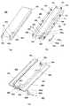
図1は本発明の実施の形態である自動販売機の主要部を示す側面断面図であり、図2は図1の自動販売機におけるレール機構を示す正面図、図3は図2のレール機構を伸長させて右斜め上方から見た斜視図、図4は図3のレール機構の構成部品を示し、(a)は固定レールの斜視図、(b)は可動レールの斜視図、(c)は係合レールの斜視図である。
Hereinafter, a vending machine according to an embodiment of the present invention will be described with reference to the drawings.
1 is a side sectional view showing a main part of a vending machine according to an embodiment of the present invention, FIG. 2 is a front view showing a rail mechanism in the vending machine of FIG. 1, and FIG. 3 is a rail mechanism of FIG. FIG. 4 is a perspective view of the rail mechanism of FIG. 3, (a) is a perspective view of a fixed rail, (b) is a perspective view of a movable rail, and (c). FIG. 3 is a perspective view of an engagement rail.

図1に示すように、この自動販売機は、前面が開口した本体キャビネット1と、本体キャビネット1の前面にヒンジにより開閉可能に支持された外扉3とからなる。前記本体キャビネット1は鋼板製の外箱の内側にウレタンフォームからなる断熱ボード1aを配設して断熱筐体として構成されている。前記本体キャビネット1の断熱ボードで囲まれた商品収納庫内は不図示の断熱仕切板により左右方向に複数の商品収納室に区画されている。各商品収納室には商品を収容するとともにその下端に商品を1個ずつ搬出する商品払出機構を有するサーペンタイン式の商品収納ラック2がそれぞれ格納されている。  As shown in FIG. 1, the vending machine includes amain body cabinet 1 having an open front surface and anouter door 3 supported on the front surface of themain body cabinet 1 so as to be opened and closed by a hinge. Themain body cabinet 1 is configured as a heat insulating housing by disposing aheat insulating board 1a made of urethane foam inside a steel plate outer box. The inside of the product storage box surrounded by the heat insulation board of themain body cabinet 1 is partitioned into a plurality of product storage rooms in the left-right direction by a heat insulating partition plate (not shown). Each merchandise storage chamber stores a serpentine-typemerchandise storage rack 2 having a merchandise dispensing mechanism that accommodates merchandise and discharges the merchandise one by one at the lower end thereof.

前記サーペンタイン式の商品収納ラック2は、左右一対のラック側板21,21の間に架け渡して上下方向に連接した湾曲セグメント22からなるセグメント列を上下方向に半ピッチずつずらして向かい合うよう配置して蛇行した商品通路23(商品収納コラム)を画成し、当該商品通路23の上端に連ねてその上部側に商品投入用のトップトレー24を配し、かつ、前記商品通路23の下部出口端側に商品搬出機構が配されているものである。そして、商品収納コラムを形成する商品通路23が商品収納庫の前後(奥行き)方向に複数段並べて配設されている。前記本体キャビネット1の前面に開口した商品投入口24aとそれぞれの商品通路23に連繋して設けられたトップトレー24によって形成される商品案内通路は商品投入口24a側から後方に向かうにしたがって低くなるように画成されている。なお、25は投入された商品の姿勢を修正する投入口ガイド、1bおよび1cは商品収納庫の内部に配設された後方フレーム材および前方フレーム材、1dは商品収納庫の天井に配設されたフレーム材1dである。  The serpentine-typeproduct storage rack 2 is arranged such that segment rows composed of curved segments 22 spanned between a pair of left and rightrack side plates 21 and 21 and vertically connected are shifted by a half pitch in the vertical direction and face each other. A meandering product passage 23 (product storage column) is defined, atop tray 24 for product introduction is arranged on the upper side of theproduct passage 23, and a lower outlet end side of theproduct passage 23. The product carrying mechanism is arranged in the. Theproduct passages 23 forming the product storage columns are arranged in a plurality of stages in the front-rear (depth) direction of the product storage. A product guide passage formed by aproduct input port 24a opened on the front surface of themain body cabinet 1 and atop tray 24 connected to eachproduct channel 23 becomes lower from theproduct input port 24a side toward the rear. It is defined as follows. Note thatreference numeral 25 denotes a slot guide for correcting the posture of the introduced product, 1b and 1c are rear frame members and front frame members provided inside the product storage, and 1d is provided on the ceiling of the product storage. Theframe material 1d.

前記本体キャビネット1の前面に開閉自在に装着された外扉3の前面には良く知られているようにディスプレイ台に載置された商品見本のディスプレイ室が形成され、このディスプレイ室の前面を覆う透明板には各商品見本に対応して設けられた商品選択ボタンを備えた商品選択ボタンユニットが配設されている。また、前記外扉3の前面には、硬貨投入口、紙幣投入口、釣銭返却口、商品取出口、返却レバー、シリンダー錠付きのハンドルロック装置などが組付けられている。なお、4は本体キャビネット1における商品収納庫の前面を閉塞して冷気若しくは暖気の流出を防止する内扉である。  As is well known, a display room for a product sample placed on a display base is formed on the front surface of theouter door 3 that is openably and closably mounted on the front surface of themain body cabinet 1, and covers the front surface of the display room. A product selection button unit having product selection buttons provided corresponding to each product sample is disposed on the transparent plate. Further, on the front surface of theouter door 3, a coin slot, a bill slot, a change return slot, a product outlet, a return lever, a handle lock device with a cylinder lock, and the like are assembled.Reference numeral 4 denotes an inner door that closes the front surface of the commodity storage in themain body cabinet 1 to prevent outflow of cool air or warm air.

さて、図1において5は前記商品収納ラック2を本体キャビネット1の商品収納庫かあら引出し可能とするために前後方向に伸縮自在なレール機構である。このレール機構5は前記本体キャビネット1の前面に開口した商品投入口24aと前記商品収納ラック2の商品通路23とを連繋するトップトレー24により形成された商品案内通路の上方域と前記本体キャビネット1における商品収納庫の天井面との間に後方に向かうにしたがって広くなる空き空間SPに配設されている。この空き空間SPは、従来ではデッドスペースとして形成されていた空間である。図1ではレール機構5が縮退した状態を示し、レール機構5は本体キャビネット1における商品収納庫の前後方向の長さよりも短く、前記空き空間SPの後方域に片寄せて商品収納庫の天井面に敷設されている。  In FIG. 1,reference numeral 5 denotes a rail mechanism that can extend and retract in the front-rear direction so that theproduct storage rack 2 can be pulled out from the product storage of themain body cabinet 1. Therail mechanism 5 includes an upper area of a product guide passage formed by atop tray 24 that connects aproduct input port 24a opened on the front surface of themain body cabinet 1 and aproduct passage 23 of theproduct storage rack 2, and themain body cabinet 1. Is disposed in an empty space SP that becomes wider toward the rear between the ceiling surface of the commodity storage. This empty space SP is a space conventionally formed as a dead space. FIG. 1 shows a state in which therail mechanism 5 is degenerated, and therail mechanism 5 is shorter than the length of the product storage in themain body cabinet 1 in the front-rear direction, and is shifted to the rear area of the empty space SP so that the ceiling surface of the product storage Is laid.

次に、前記レール機構5の構成について図2乃至図4を用いて説明する。前記レール機構5は厚板鋼板により形成された固定レール6、可動レール7および係合レール8からなり、固定レール6が本体キャビネット1における商品収納庫の天井面に前後方向に敷設され、この固定レール6に可動レール7がスライド移動自在に支持され、この可動レール7に係合レール8がスライド移動自在に支持された構成となる。前記固定レール6、可動レール7および係合レール8はそれぞれ略同一の長さを有している。  Next, the configuration of therail mechanism 5 will be described with reference to FIGS. Therail mechanism 5 includes afixed rail 6, amovable rail 7, and anengaging rail 8 formed of a thick steel plate. The fixedrail 6 is laid in the front-rear direction on the ceiling surface of the product storage in themain body cabinet 1. Themovable rail 7 is slidably supported by therail 6, and the engagingrail 8 is slidably supported by themovable rail 7. The fixedrail 6, themovable rail 7 and the engagingrail 8 have substantially the same length.

前記レール機構5を構成する固定レール6は逆Uチャンネル状に形成され、左右側壁から内方に向かって突出するローラガイド部61が形成され、逆Uチャンネル状の底壁前方端近傍に切り起しにより下方に突出するストッパ片62が形成されている。また、固定レール6の左右側壁の後方端縁には鉤状の係合片63(図3、図4では右側の側壁の係合片63が見えている)が形成され、固定レール6の底壁前方端部にはボルト9の貫通穴64が形成されている。逆Uチャンネル状の固定レール6に遊嵌される可動レール7は全体として固定レール6と同様に逆Uチャンネル状に形成され、逆Uチャンネル状の底壁に凹部71を形成した構成となる。前記可動レール7における左右側壁72,72の内壁には複数のローラ10(ローラ10の軸を10aで示している)が取付けられ、前記側壁72,72の外面には可動レール7の前後方向の略中央位置にローラ11が取付けられている。なお、前記可動レール7における左右側壁72,72の内面に取付けられた最後尾のローラ12は可動レール7の姿勢を維持するものであり、ローラ10よりも水平線に対して上段に位置するように取付けられている。  The fixedrail 6 constituting therail mechanism 5 is formed in an inverted U channel shape, and is formed with aroller guide portion 61 that protrudes inward from the left and right side walls, and is cut and raised near the front end of the bottom wall of the inverted U channel shape. Thus, astopper piece 62 protruding downward is formed. In addition, hook-like engagement pieces 63 (theengagement pieces 63 on the right side wall are visible in FIGS. 3 and 4) are formed on the rear edges of the left and right side walls of the fixedrail 6. A throughhole 64 of thebolt 9 is formed at the front end of the wall. Themovable rail 7 loosely fitted to the inverted U-channelfixed rail 6 is formed in an inverted U-channel shape as in the fixedrail 6 as a whole, and has a configuration in which arecess 71 is formed in the inverted U-channel bottom wall. A plurality of rollers 10 (the axis of theroller 10 is indicated by 10a) are attached to the inner walls of the left andright side walls 72, 72 of themovable rail 7, and the front and rear directions of themovable rail 7 are disposed on the outer surfaces of theside walls 72, 72. Aroller 11 is attached at a substantially central position. Therearmost roller 12 attached to the inner surfaces of the left andright side walls 72, 72 of themovable rail 7 maintains the posture of themovable rail 7, and is positioned higher than theroller 10 with respect to the horizontal line. Installed.

また、前記可動レール7の凹部71には可動レール7の前後方向の略中央位置には上方に突出するストッパ片76が設けられ、凹部71の前方端部にストッパモジュール73が取付けられている。前記ストッパ片76はL字状に形成されてなり、その一方の脚片を前記凹部71の下面側から該凹部71の底壁に形成された穴(不図示)を介して上方に突出するように配設するとともに他方の脚片をねじにより固着して取付けられている。前記ストッパモジュール73は図4の(b)に併記した可動ストッパ部材74および補強部材75からなる。前記可動ストッパ部材74は縦断面コ字状をなし、上方の脚片にねじ穴741が設けられ、下方の脚片にストッパ片742が曲げ起しにより設けられている。前記補強部材75はねじ穴751が設けられた取付部752から下方に折り曲げられた二股状の係合片753が設けられている。前記可動ストッパ部材74は可動レール7の凹部71底壁の下面に配設される一方、前記補強部材75が当該凹部71底壁の上面に配設されている。なお、前記可動レール7の凹部71底壁には前記補強部材75の係合片753が貫通可能な穴が形成されているものである。そして、前記補強部材75における二股状の係合片753の背後に可動ストッパ部材74のストッパ片742が位置する状態にそれぞれねじ穴751,741を介してねじ91(図2参照)等により取付けられる。なお、前記ねじ91は補強部材75を固定するねじであり、可動ストッパ部材74のねじは前記ねじ91に隠れて見えないが、そのねじとして段付ねじが用いられている。したがって、前記可動ストッパ部材74は当該段付ねじを中心に旋回させることができ、後述する係合レール8を組付ける際にストッパ片742を補強部材75の二股状の係合片753の背後から退避させることができるように構成されている。また、常時においては可動ストッパ部材74のストッパ片742を補強部材75の係合片753の背後に位置させてねじ92(図2参照)により固定して位置決めしている。  Further, astopper piece 76 protruding upward is provided at a substantially central position in the front-rear direction of themovable rail 7 in therecess 71 of themovable rail 7, and astopper module 73 is attached to the front end of therecess 71. Thestopper piece 76 is formed in an L shape, and one leg piece protrudes upward from a lower surface side of therecess 71 through a hole (not shown) formed in the bottom wall of therecess 71. And the other leg piece is fixedly attached with a screw. Thestopper module 73 includes amovable stopper member 74 and a reinforcingmember 75 which are also shown in FIG. Themovable stopper member 74 has a U-shaped vertical cross section, ascrew hole 741 is provided in the upper leg piece, and astopper piece 742 is provided by bending up the lower leg piece. The reinforcingmember 75 is provided with abifurcated engagement piece 753 bent downward from anattachment portion 752 provided with ascrew hole 751. Themovable stopper member 74 is disposed on the bottom surface of the bottom wall of therecess 71 of themovable rail 7, while the reinforcingmember 75 is disposed on the top surface of the bottom wall of therecess 71. The bottom wall of therecess 71 of themovable rail 7 is formed with a hole through which theengagement piece 753 of the reinforcingmember 75 can pass. Then, thestopper member 742 of themovable stopper member 74 is positioned behind the bifurcatedengagement piece 753 of the reinforcingmember 75 by screws 91 (see FIG. 2) or the like via screw holes 751 and 741 respectively. . Thescrew 91 is a screw for fixing the reinforcingmember 75, and the screw of themovable stopper member 74 is hidden behind thescrew 91 and cannot be seen, but a stepped screw is used as the screw. Therefore, themovable stopper member 74 can be turned around the stepped screw, and thestopper piece 742 can be moved from behind the bifurcatedengagement piece 753 of the reinforcingmember 75 when theengagement rail 8 described later is assembled. It is configured so that it can be evacuated. In addition, thestopper piece 742 of themovable stopper member 74 is normally positioned behind the engagingpiece 753 of the reinforcingmember 75 and fixed by a screw 92 (see FIG. 2) for positioning.

前記レール機構5を構成する係合レール8は左右両端に起立するラック係合突起81,81を有する広幅、つまり、図2に示すようにサーペンタイン式商品収納ラック2の左右一対のラック側板21,21の間隔に略一致する広幅の板材からなり、その中央付近に上方に向けて切り起こされたストッパ片82が設けられ、その前端には曲げ起しにより保護突起83が形成されている。前記係合レール8の板面上には前後方向に2条の連結部材84,84が溶接により固着されている。前記連結部材84,84は断面鉤状に形成され、鉤の先端がそれぞれ外方を向いている。なお、ラック係合突起81,81の後端には商品収納ラック2のラック側板21を係合させる際の位置決め突起811,811が形成されている。  Theengagement rail 8 constituting therail mechanism 5 has a wide width havingrack engagement protrusions 81 and 81 standing at both left and right ends, that is, as shown in FIG. 2, a pair of left and rightrack side plates 21 of the serpentine typeproduct storage rack 2. Astopper plate 82 is formed in the vicinity of the center thereof and is cut and raised upward, and aprotective projection 83 is formed by bending up at the front end. On the plate surface of the engagingrail 8, two connectingmembers 84, 84 are fixed in the front-rear direction by welding. The connectingmembers 84, 84 are formed in a cross-sectional shape, and the tips of the hooks face outward. In addition, positioningprotrusions 811 and 811 for engaging therack side plate 21 of theproduct storage rack 2 are formed at the rear ends of therack engaging protrusions 81 and 81.

次に、前記レール機構5の組立について説明する。まず、前記固定レール6を図1に示した本体キャビネット1の商品収納庫における空き空間SPの後方域に片寄せて商品収納庫の天井面に敷設する。すなわち、前記固定レール6の後方端部に形成された鉤状の係合片63を商品収納庫の内部に配設された後方フレーム材1bに形成された係合穴(不図示)に係合させる。次いで、固定レール6の前方端部に形成された貫通穴64(図4の(a)参照)を介してボルト9を商品収納庫の内部に配設されたフレーム材1dに設けた雌ねじ穴に螺合させて締め付ける。これにより固定レール6が商品収納庫の天井面に敷設される。なお、前記フレーム材1dは商品収納庫の内部に配設された前方フレーム材1cと後方フレーム材1bに架け渡された左右の支持フレーム材(不図示)に左右方向に架け渡されたものである。  Next, the assembly of therail mechanism 5 will be described. First, the fixedrail 6 is laid out on the ceiling surface of the product storage unit by being shifted to the rear area of the empty space SP in the product storage unit of themain body cabinet 1 shown in FIG. That is, the hook-like engagement piece 63 formed at the rear end of the fixedrail 6 is engaged with an engagement hole (not shown) formed in therear frame member 1b disposed inside the product storage. Let Next, thebolt 9 is inserted into the female screw hole provided in theframe material 1d disposed inside the commodity storage through the through hole 64 (see FIG. 4A) formed in the front end portion of the fixedrail 6. Screw in and tighten. Thereby, the fixedrail 6 is laid on the ceiling surface of the product storage. Theframe material 1d is bridged in the left-right direction on left and right support frame members (not shown) spanned between thefront frame material 1c and therear frame material 1b disposed inside the product storage. is there.

次いで、商品収納庫の天井面に敷設された固定レール6の前方から可動レール7を嵌め込む。この場合、可動レール7に取付けられた最後尾のローラ12が固定レール6の底壁内面に当接し、可動レール7の左右側壁72,72外面に設けたローラ11が固定レール6のローラガイド部61に乗るように相互の位置関係を保つ。なお、図4の(b)に示した可動レール7の凹部71に設けたストッパ片76は可動レール7を固定レール6に組み付ける際には取り外されており、固定レール6の前方から可動レール7を嵌め込む際にストッパ片76が固定レール6のストッパ片62に当接することがなく、また、可動レール7が前傾した場合にも可動レール7に取付けられた最後尾のローラ12が固定レール6の底壁内面に当接するので、可動レール7をスムーズに嵌め込むことができる。このようにして固定レール6に嵌め込まれた可動レール7には前記ストッパ片76を次のようにして取付ける。すなわち、可動レール7の下方からL字状に形成されたストッパ片76の一方の脚片を可動レール7の凹部71の下面側から該凹部71の底壁に形成された穴を介して上方に突出させた後、他方の脚片をねじにより前記凹部71の底壁に固着する。このように取付けられたストッパ片76は可動レール7が前方へ移動した場合に固定レール6のストッパ片62に当接し、可動レール7の前方への移動を規制して固定レール6と可動レール7の連結が維持される。  Next, themovable rail 7 is fitted from the front of the fixedrail 6 laid on the ceiling surface of the product storage. In this case, thelast roller 12 attached to themovable rail 7 contacts the inner surface of the bottom wall of the fixedrail 6, and therollers 11 provided on the outer surfaces of the left andright side walls 72, 72 of themovable rail 7 are the roller guide portions of the fixedrail 6. The mutual positional relationship is maintained so as to ride 61. Thestopper piece 76 provided in theconcave portion 71 of themovable rail 7 shown in FIG. 4B is removed when themovable rail 7 is assembled to the fixedrail 6, and themovable rail 7 is moved from the front of the fixedrail 6. Thestopper piece 76 does not come into contact with thestopper piece 62 of the fixedrail 6 and thelast roller 12 attached to themovable rail 7 is fixed to the fixed rail even when themovable rail 7 is tilted forward. 6 is in contact with the inner surface of thebottom wall 6 so that themovable rail 7 can be fitted smoothly. Thestopper piece 76 is attached to themovable rail 7 fitted in the fixedrail 6 in the following manner. That is, one leg piece of thestopper piece 76 formed in an L shape from below themovable rail 7 is moved upward from the lower surface side of theconcave portion 71 of themovable rail 7 through a hole formed in the bottom wall of theconcave portion 71. After protruding, the other leg piece is fixed to the bottom wall of therecess 71 with a screw. Thestopper piece 76 attached in this manner abuts against thestopper piece 62 of the fixedrail 6 when themovable rail 7 moves forward, and restricts the forward movement of themovable rail 7 to restrict the fixedrail 6 and themovable rail 7. Is maintained.

次いで、固定レール6に組み込まれた可動レール7の前方から係合レール8を組み付ける。この場合、係合レール8に設けた2条の連結部材84,84(の鉤)が可動レール7の左右側壁72,72内面に設けたローラ10の上に乗るように相互の位置関係を保つ。ここで、図4の(b)に示したように、可動レール7にはストッパモジュール73が取付けられており、ストッパモジュール73を構成する可動ストッパ部材74のストッパ片742が補強部材75の二股状の係合片753の背後に位置している場合には、当該ストッパ片742に係合レール8のストッパ片82が当接するので係合レール8を可動レール7に組み付けることができない。なお、可動レール7のストッパモジュール73を構成する補強部材75はその係合片753の二股の間を係合レール8のストッパ片82が通過できるように位置決めして取付けられている。そのため、係合レール8を可動レール7に組み付けるにあたり次の作業を行う。すなわち、可動レール7のストッパモジュール73を構成する可動ストッパ部材74のストッパ片742を補強部材75に固着しているねじ92を外して前記可動ストッパ部材74を旋回させる、つまり、可動ストッパ部材74を可動レール7の凹部71の底壁下面に取付けている段付ねじを中心として時計方向に旋回させ、前記補強部材75の二股状の係合片753の背後に位置していた可動ストッパ部材74のストッパ片742を補強部材75の二股状の係合片753の背後から退避させる。このように可動ストッパ部材74のストッパ片742を前記補強部材75の二股状の係合片753の背後から退避させた状態で係合レール8を可動レール7に組み付けると係合レール8のストッパ片82が補強部材75の係合片753の二股の間を通過してストッパモジュール73の後方に移動する。この状態で可動ストッパ部材74を反時計方向に旋回させてそのストッパ片742を元の位置、すなわち、補強部材75の二股状の係合片753の背後に位置する元の位置に戻し、ストッパ片742をねじ92により補強部材75に固定する。これにより係合レール8が前方へ移動すると係合レール8のストッパ片82が可動レール7の可動ストッパ部材74のストッパ片742に当接することとなり可動レール7と係合レール8との連結が維持される。  Next, theengagement rail 8 is assembled from the front of themovable rail 7 incorporated in the fixedrail 6. In this case, the mutual positional relationship is maintained so that the two connectingmembers 84, 84 (the flanges) provided on theengagement rail 8 ride on therollers 10 provided on the inner surfaces of the left andright side walls 72, 72 of themovable rail 7. . Here, as shown in FIG. 4B, astopper module 73 is attached to themovable rail 7, and thestopper piece 742 of themovable stopper member 74 constituting thestopper module 73 is a bifurcated shape of the reinforcingmember 75. When theengagement piece 753 is positioned behind theengagement piece 753, theengagement rail 8 cannot be assembled to themovable rail 7 because thestopper piece 82 of theengagement rail 8 contacts thestopper piece 742. The reinforcingmember 75 constituting thestopper module 73 of themovable rail 7 is positioned and attached so that thestopper piece 82 of theengagement rail 8 can pass between the two forks of theengagement piece 753. Therefore, the following work is performed when theengagement rail 8 is assembled to themovable rail 7. That is, thescrew 92 that fixes thestopper piece 742 of themovable stopper member 74 constituting thestopper module 73 of themovable rail 7 to the reinforcingmember 75 is removed, and themovable stopper member 74 is turned. Themovable stopper member 74 is pivoted clockwise around a stepped screw attached to the bottom surface of the bottom wall of theconcave portion 71 of themovable rail 7 and located behind the bifurcatedengagement piece 753 of the reinforcingmember 75. Thestopper piece 742 is retracted from behind the bifurcatedengagement piece 753 of the reinforcingmember 75. When theengagement rail 8 is assembled to themovable rail 7 with thestopper piece 742 of themovable stopper member 74 thus retracted from the back of the bifurcatedengagement piece 753 of the reinforcingmember 75, the stopper piece of theengagement rail 8 is assembled. 82 passes between the two forks of theengaging piece 753 of the reinforcingmember 75 and moves to the rear of thestopper module 73. In this state, themovable stopper member 74 is turned counterclockwise to return thestopper piece 742 to the original position, that is, the original position located behind the bifurcatedengagement piece 753 of the reinforcingmember 75, and the stopper piece. 742 is fixed to the reinforcingmember 75 with ascrew 92. As a result, when theengagement rail 8 moves forward, thestopper piece 82 of theengagement rail 8 comes into contact with thestopper piece 742 of themovable stopper member 74 of themovable rail 7 and the connection between themovable rail 7 and theengagement rail 8 is maintained. Is done.

前記本体キャビネット1の商品収納庫の天井面に敷設されたレール機構5には次のようにしてサーペンタイン式の商品収納ラック2が取付けられる。すなわち、レール機構5を図3に示すように伸長させた状態で係合レール8の左右両端に形成されたラック係合突起81,81に商品収納ラック2の左右一対のラック側板21,21の上端に形成されたフック211を係合させる。この場合、ラック係合突起81,81の後端に形成された位置決め突起811,811(図4の(c)参照)にラック側板21,21の後方の端縁を当接させるようにして位置決めする。このようにラック側板21,21を係合レール8に係合させた際、図1に示すようにラック側板21,21の幅(前後方向の長さ)に対してレール機構5(係合レール8)の長さが短い分だけラック側板21,21の前方域は係合レール8(ラック係合突起81,81)に係合(保持)されないこととなる。しかしながら、その区域は相互の係合区域に比べて僅かであるので係合レール8による商品収納ラック2の保持に支障はない。  A serpentine-typeproduct storage rack 2 is attached to therail mechanism 5 laid on the ceiling surface of the product storage of themain body cabinet 1 as follows. That is, with therail mechanism 5 extended as shown in FIG. 3, therack engaging protrusions 81, 81 formed on the left and right ends of the engagingrail 8 are connected to the pair of left and rightrack side plates 21, 21 of theproduct storage rack 2. Thehook 211 formed at the upper end is engaged. In this case, the positioningprotrusions 811, 811 (see FIG. 4C) formed at the rear ends of therack engaging protrusions 81, 81 are positioned so that the rear edges of therack side plates 21, 21 are in contact with each other. To do. When therack side plates 21 and 21 are engaged with the engagement rails 8 as described above, the rail mechanism 5 (engagement rails) with respect to the width (length in the front-rear direction) of therack side plates 21 and 21 as shown in FIG. The front area of therack side plates 21 and 21 is not engaged (held) with the engagement rail 8 (rackengagement protrusions 81 and 81) by the short length of 8). However, since the area is small compared with the mutual engagement area, there is no problem in holding thecommodity storage rack 2 by theengagement rail 8.

前述したように商品収納ラック2を係合レール8に吊下げ支持した後、レール機構5を縮退させることによって商品収納ラック2は商品収納庫に格納される。商品収納庫に格納した商品収納ラック2への商品の補充は従来と同様に商品投入口24aから商品を投入することにより行われる。この商品補充の際、本発明の実施の形態における自動販売機においてはレール機構5が商品収納庫の空き空間SPの後方域に片寄せて敷設されていることから、最上段の商品投入口24aから投入される商品に対してレール機構5が邪魔をすることがない。つまり、最上段の商品投入口24aを商品収納庫の天井面に近接して設けることができ、これにより最上段の商品投入口24aの位置を従来の自動販売機と同一の位置に設けることが可能となる。したがって、商品収納ラック2を商品収納庫から前方に引出し可能に支持する伸縮自在なレール機構5を敷設した場合にも商品収納ラック2に収容する商品の数量が減少することはないものである。なお、係合レール8の前端には曲げ起しにより保護突起83(図4の(c)参照)が設けられているので、商品補充の際に商品が衝突しても商品を傷つけることがない。  As described above, theproduct storage rack 2 is stored in the product storage by retracting therail mechanism 5 after theproduct storage rack 2 is suspended and supported by theengagement rail 8. The replenishment of the product to theproduct storage rack 2 stored in the product storage is performed by inputting the product from theproduct input port 24a as in the conventional case. At the time of this product replenishment, in the vending machine according to the embodiment of the present invention, therail mechanism 5 is laid out in the rear area of the empty space SP of the product storage, so that theproduct input port 24a at the uppermost stage is installed. Therail mechanism 5 does not interfere with the products that are put in. In other words, the uppermostproduct input port 24a can be provided close to the ceiling surface of the product storage, so that the uppermostproduct input port 24a can be provided at the same position as a conventional vending machine. It becomes possible. Therefore, the number of products stored in theproduct storage rack 2 does not decrease even when thetelescopic rail mechanism 5 that supports theproduct storage rack 2 so as to be able to be pulled out from the product storage is installed. Since the front end of theengagement rail 8 is provided with a protective protrusion 83 (see FIG. 4C) by bending, the product will not be damaged even if the product collides during product replenishment. .

次に、本発明における異なる実施の形態である自動販売機を図5乃至図7に基づいて説明する。図5は本発明の異なる実施の形態である自動販売機におけるレール機構を示す正面図、図6は図5のレール機構を伸長させて右斜め上方から見た斜視図、図7は図6のレール機構の構成部品を示し、(a)は固定レールの斜視図、(b)は可動レールの斜視図、(c)は係合レールの斜視図である。なお、レール機構の商品収納庫の天井面への敷設位置は図1に示した実施の形態の自動販売機と同一であるので、ここではその説明を省略する。  Next, a vending machine according to another embodiment of the present invention will be described with reference to FIGS. FIG. 5 is a front view showing a rail mechanism in a vending machine according to a different embodiment of the present invention, FIG. 6 is a perspective view of the rail mechanism of FIG. The components of a rail mechanism are shown, (a) is a perspective view of a fixed rail, (b) is a perspective view of a movable rail, and (c) is a perspective view of an engagement rail. In addition, since the laying position of the rail mechanism on the ceiling surface of the product storage is the same as that of the vending machine of the embodiment shown in FIG. 1, the description thereof is omitted here.

図5において500でレール機構を示し、このレール機構500は厚板鋼板により形成された固定レール600、可動レール700および係合レール800からなり、固定レール600が本体キャビネット1の商品収納庫における空き空間SP(図1参照)の後方域に片寄せて商品収納庫の天井面に敷設され、この固定レール600に可動レール700がスライド移動自在に支持され、この可動レール700に係合レール800がスライド移動自在に支持された構成となる。前記固定レール600、可動レール700および係合レール800はそれぞれ略同一の長さを有している。  In FIG. 5,reference numeral 500 denotes a rail mechanism. Therail mechanism 500 includes a fixedrail 600, amovable rail 700, and anengagement rail 800 formed of thick steel plates, and the fixedrail 600 is an empty space in the commodity storage of themain body cabinet 1. Themovable rail 700 is slidably supported on the fixedrail 600 and is slidably moved to the rear surface of the space SP (see FIG. 1). It is configured to be slidably supported. The fixedrail 600, themovable rail 700, and theengagement rail 800 have substantially the same length.

前記レール機構500を構成する固定レール600は逆Uチャンネル状に形成され、左右側壁から外方に向かって突出するローラガイド部601が形成され、逆Uチャンネル状の底壁前方側右端近傍に切起しにより下方に突出するストッパ片602が形成されている。また、固定レール600の左右側壁の後方端部には鉤状の係合片603(図6、図7では右側の側壁の係合片603が見えている)が形成され、固定レール600の底壁前方端部にはボルト9の貫通穴604が形成されるとともに左右側壁の前縁には内方に向かって突出するストッパ605,606が形成されている。逆Uチャンネル状の固定レール600に差し込まれる可動レール700は全体としてUチャンネル状に形成され、逆Uチャンネル状の底壁に凸部701を形成した構成となる。前記可動レール700における左右側壁702,702の内面には、左右側壁702,702の高さより直径の小さいローラ100、101がそれぞれ取付けられている。そして、ローラ100はその周面の一部が可動レール700の左右側壁702,702より上方に突出するようにローラ101とは水平線に対して段差を有するように軸支されている。また、前記可動レール700の凸部701の後方端部は一部を切り欠いて左右脚片に軸支されたローラ102が取付けられている。なお、前記可動レール700に取付けられたローラ102はローラ100,101よりも水平線に対して上段に位置するように取付けられている。  The fixedrail 600 constituting therail mechanism 500 is formed in an inverted U channel shape, and is formed with aroller guide portion 601 that protrudes outward from the left and right side walls, and is cut in the vicinity of the right end on the front side of the inverted U channel shape bottom wall. Astopper piece 602 that protrudes downward is formed by raising. Also, hook-shaped engagement pieces 603 (theengagement pieces 603 on the right side wall are visible in FIGS. 6 and 7) are formed at the rear ends of the left and right side walls of the fixedrail 600, and the bottom of the fixedrail 600 is formed. A throughhole 604 of thebolt 9 is formed at the front end portion of the wall, andstoppers 605 and 606 projecting inward are formed at the front edges of the left and right side walls. Themovable rail 700 inserted into the inverted U channel fixedrail 600 is formed in a U channel shape as a whole, and has a configuration in which aconvex portion 701 is formed on the bottom wall of the inverted U channel.Rollers 100 and 101 having a diameter smaller than the height of the left andright side walls 702 and 702 are attached to the inner surfaces of the left andright side walls 702 and 702 of themovable rail 700, respectively. Theroller 100 is pivotally supported so as to have a step with respect to the horizontal line so that a part of its peripheral surface protrudes above the left andright side walls 702 and 702 of themovable rail 700. The rear end of theconvex portion 701 of themovable rail 700 is partly cut out and aroller 102 pivotally supported on the left and right leg pieces is attached. Theroller 102 attached to themovable rail 700 is attached so as to be positioned in the upper stage with respect to the horizontal line relative to therollers 100 and 101.

また、前記可動レール700の凸部701にはその右側脚片における前後方向の略中央位置に右方に突出するストッパ片706が取付けられ、その凸部701の右側脚片前方寄りにストッパ構成部材703が取付けられている。前記ストッパ片706は平板状に形成されてなり、その一端を前記凸部701の内面側から該凸部701の右側脚片に形成された穴711を介して右方に突出するように配設するとともに他端を凸部701内面にねじにより固着して取付けられている。前記ストッパ構成部材703は図7の(b)に併記したとおり、前後方向に延在する平板状の本体部703aと、この本体部703aに連結された縦断面L字状の係合部703bからなり、この係合部703bにはねじ穴703cが形成されている。前記可動ストッパ構成部材703は段付ねじ901により回動自在に取付けられ、この段付ねじ901を取付けるために可動レール700の右側の側壁702に工具挿入穴702aが穿孔されている。前記ストッパ構成部材703の係合部703bは凸部701の右側脚片に形成された開口701aを介して凸部701内部に進入しており、常時は凸部701の右側脚片の前縁に形成された係止突起704の背後に位置してねじ902により係止突起704に固着されている。この係止突起704は第1の実施の形態の可動レール7に設けられたストッパモジュール73の補強部材75における二股状の係合片753と同様に形成されており、二股状の係合片の間(下方に開放する溝内)にねじ902が挿入される。  Further, astopper piece 706 protruding rightward is attached to theconvex portion 701 of themovable rail 700 at a substantially central position in the front-rear direction of the right leg piece, and a stopper constituting member is located closer to the front side of the right leg piece of theconvex portion 701. 703 is attached. Thestopper piece 706 is formed in a flat plate shape, and one end thereof is disposed so as to protrude rightward from the inner surface side of theconvex portion 701 through ahole 711 formed in the right leg piece of theconvex portion 701. In addition, the other end is fixedly attached to the inner surface of theconvex portion 701 with a screw. As shown in FIG. 7B, thestopper constituting member 703 includes a flat plate-likemain body portion 703a extending in the front-rear direction and an engagingportion 703b having an L-shaped longitudinal section connected to themain body portion 703a. Thus, ascrew hole 703c is formed in the engagingportion 703b. The movablestopper constituting member 703 is rotatably attached by a steppedscrew 901, and atool insertion hole 702a is formed in theright side wall 702 of themovable rail 700 in order to attach the steppedscrew 901. The engagingportion 703b of thestopper constituting member 703 enters theconvex portion 701 through anopening 701a formed in the right leg piece of theconvex portion 701, and is always at the front edge of the right leg piece of theconvex portion 701. It is located behind the formedlocking projection 704 and is fixed to the lockingprojection 704 with ascrew 902. This lockingprojection 704 is formed in the same manner as thebifurcated engagement piece 753 in the reinforcingmember 75 of thestopper module 73 provided on themovable rail 7 of the first embodiment. Ascrew 902 is inserted between them (in the groove opened downward).

前記レール機構500を構成する係合レール800は左右両端に起立するラック係合突起801,801を有する広幅、つまり、図5に示すようにサーペンタイン式商品収納ラック2の左右一対のラック側板21,21の間隔に略一致する広幅の板材からなり、その中央付近に上方に向けて切り起こされたストッパ片802が設けられ、その前端には曲げ起しにより保護突起803が形成されている。前記係合レール800の板面上に溶接により固着された前後方向に2条の連結部材804,804は断面鉤状に形成され、鉤の先端がそれぞれ内方を向いている。また、前記係合レール800の後端寄りには姿勢維持用ローラ805が取付けられ、係合レール800の前端に起立する取付脚片807に「へ」の字状の係合ばね806が固着されている。この係合ばね806は前記可動レール700のストッパ構成部材703における係合部703bの後縁に係合するように構成されている。そして、前記係合レール800の前端の保護突起803に段付ねじ903により旋回可能に取付けられた係合片808が設けられている。この係合片808は図7の(c)に併記したとおり、先端に下方に向いたフック808a、保護突起803を跨いで当該保護突起803の上に載る座部808bおよび指掛け部808cが形成されている。  The engagingrail 800 constituting therail mechanism 500 has a wide width havingrack engaging protrusions 801 and 801 standing at both left and right ends, that is, a pair of left and rightrack side plates 21 of the serpentine typeproduct storage rack 2 as shown in FIG. Astopper piece 802 which is made of a wide plate material substantially coincident with the interval of 21 and is cut and raised upward in the vicinity of the center thereof, and aprotective projection 803 is formed at the front end thereof by bending. Two connectingmembers 804 and 804 are formed in a cross-sectional shape in the front-rear direction fixed on the plate surface of theengagement rail 800 by welding, and the leading ends of the hooks face inward. Further, aposture maintaining roller 805 is attached to the vicinity of the rear end of theengagement rail 800, and anengagement spring 806 in the shape of a letter “he” is fixed to theattachment leg piece 807 standing at the front end of theengagement rail 800. ing. Theengagement spring 806 is configured to engage with the rear edge of theengagement portion 703b in thestopper component 703 of themovable rail 700. Further, anengagement piece 808 is provided on theprotective projection 803 at the front end of theengagement rail 800 so as to be turnable by a steppedscrew 903. As shown in FIG. 7C, the engagingpiece 808 has ahook 808a facing downward, aseat 808b and afinger hook 808c that are placed on theprotective protrusion 803 across theprotective protrusion 803. ing.

次に、前記レール機構500の組立について説明する。まず、前記固定レール600を図1に示した本体キャビネット1の商品収納庫における空き空間SPの後方域に片寄せて商品収納庫の天井面に敷設する。この固定レール600の天井面への敷設方法は図1乃至図4に示した第1の実施の形態と同様に、固定レール600の後方端部に形成された鉤状の係合片603を商品収納庫の内部に配設された後方フレーム材1bに形成された係合穴(不図示)に係合させる。次いで、固定レール600の前方端部に形成された貫通穴604(図7の(a)参照)を介してボルト9を商品収納庫の内部に配設されたフレーム材1dに設けた雌ねじ穴に螺合させて締め付ける。これにより固定レール600が商品収納庫の天井面に敷設される。  Next, assembly of therail mechanism 500 will be described. First, the fixedrail 600 is laid on the ceiling surface of the product storage unit by being shifted to the rear area of the empty space SP in the product storage unit of themain body cabinet 1 shown in FIG. The method of laying the fixedrail 600 on the ceiling surface is similar to the first embodiment shown in FIGS. 1 to 4 in that the hook-shapedengagement piece 603 formed at the rear end of the fixedrail 600 is used as a product. It engages with an engagement hole (not shown) formed in therear frame member 1b disposed inside the storage. Next, thebolt 9 is inserted into a female screw hole provided in theframe material 1d disposed inside the product storage through a through hole 604 (see FIG. 7A) formed in the front end of the fixedrail 600. Screw in and tighten. Thereby, the fixedrail 600 is laid on the ceiling surface of the product storage.

次いで、商品収納庫の天井面に敷設された固定レール600の前方から可動レール700を嵌め込む。この場合、可動レール700に取付けられた最後尾のローラ102が固定レール600の底壁内面に当接し、可動レール700の左右側壁702,702内面に設けたローラ101が固定レール600のローラガイド部601に乗るように相互の位置関係を保つ。なお、図7の(b)に示した可動レール700の凸部701に設けたストッパ片706は可動レール700を固定レール600に組み付ける際には取り外されており、固定レール600の前方から可動レール700を嵌め込む際にストッパ片706が固定レール600のストッパ片602に当接することがなく、また、可動レール700が前傾した場合にも可動レール700に取付けられた最後尾のローラ102が固定レール600の底壁内面に当接するので、可動レール700をスムーズに嵌め込むことができる。このようにして固定レール600に嵌め込まれた可動レール700には前記ストッパ片706を次のようにして取付ける。すなわち、前記ストッパ片706の一端を可動レール700の凸部701の内面側から該凸部701の右側脚片に形成された穴711を介して右方に突出させた後、他方の脚片をねじにより前記凸部701の底壁に固着する。このように取付けられたストッパ片706は可動レール700が前方へ移動した場合に固定レール600のストッパ片602に当接し、可動レール700の前方への移動を規制して固定レール600と可動レール700の連結が維持される。  Next, themovable rail 700 is fitted from the front of the fixedrail 600 laid on the ceiling surface of the product storage. In this case, thelast roller 102 attached to themovable rail 700 contacts the inner surface of the bottom wall of the fixedrail 600, and therollers 101 provided on the inner surfaces of the left andright side walls 702 and 702 of themovable rail 700 are roller guide portions of the fixedrail 600. The mutual positional relationship is maintained so as to ride 601. 7B, thestopper piece 706 provided on theconvex portion 701 of themovable rail 700 is removed when themovable rail 700 is assembled to the fixedrail 600, and themovable rail 700 is moved from the front of the fixedrail 600. Thestopper piece 706 does not contact thestopper piece 602 of the fixedrail 600 when the 700 is fitted, and thelast roller 102 attached to themovable rail 700 is fixed even when themovable rail 700 is tilted forward. Since it contacts the inner surface of the bottom wall of therail 600, themovable rail 700 can be fitted smoothly. Thestopper piece 706 is attached to themovable rail 700 fitted to the fixedrail 600 as follows. That is, after one end of thestopper piece 706 protrudes rightward from the inner surface side of theconvex portion 701 of themovable rail 700 through thehole 711 formed in the right leg piece of theconvex portion 701, the other leg piece is It is fixed to the bottom wall of theconvex portion 701 with a screw. Thestopper piece 706 attached in this way abuts against thestopper piece 602 of the fixedrail 600 when themovable rail 700 moves forward, and restricts the forward movement of themovable rail 700 to restrict the fixedrail 600 and themovable rail 700. Is maintained.

次いで、固定レール600に組み込まれた可動レール700の前方から係合レール800を組み付ける。この場合、係合レール800に設けた2条の連結部材804,804(の鉤)が可動レール700の左右側壁702,702内面に設けたローラ101の上に乗るように相互の位置関係を保つ。ここで、図7の(b)に示したように、可動レール700にはストッパ構成部材703が取付けられており、ストッパ構成部材703の係合部703bが係止突起704(の二股状の係合片)の背後に位置している場合には、当該ストッパ構成部材703の係合部703bに係合レール800のストッパ片802が当接するので係合レール800を可動レール700に組み付けることができない。なお、可動レール700の係止突起704はその係合片の二股の間を係合レール800のストッパ片802が通過できるように位置決めして取付けられている。そのため、係合レール800を可動レール700に組み付けるにあたり次の作業を行う。すなわち、可動レール700のストッパ構成部材703を旋回させる、つまり、可動レール700の係止突起704にストッパ構成部材703を固着しているねじ902を取り外した後、段付ねじ901を中心としてストッパ構成部材703を上方に旋回させ、前記可動レール700の係止突起704の背後に位置していたストッパ構成部材703の係合部703bを係止突起704の二股状の係合片の背後から退避させる。このようにストッパ構成部材703の係合部703bを前記係止突起704の二股状の係合片の背後から退避させた状態で係合レール800を可動レール700に組み付けると係合レール800のストッパ片802が係止突起704の二股の間を通過してストッパ構成部材703の後方に移動する。この状態でストッパ構成部材703を逆方向に旋回させて元の位置、すなわち、ストッパ構成部材703の係合部703bが係止突起704の二股状の係合片の背後に位置する元の位置に戻しねじ902により固定する。これにより係合レール800が前方へ移動すると係合レール800のストッパ片802が可動レール700のストッパ構成部材703の係合部703bに当接することとなり可動レール700と係合レール800との結合が保たれる。  Next, theengagement rail 800 is assembled from the front of themovable rail 700 incorporated in the fixedrail 600. In this case, the mutual positional relationship is maintained so that the two connectingmembers 804 and 804 (the collars) provided on theengagement rail 800 ride on therollers 101 provided on the inner surfaces of the left andright side walls 702 and 702 of themovable rail 700. . Here, as shown in FIG. 7B, themovable rail 700 is provided with astopper constituting member 703, and the engagingportion 703b of thestopper constituting member 703 has an engaging projection 704 (a bifurcated engagement). If thestopper piece 802 of the engagingrail 800 is in contact with the engagingportion 703b of thestopper constituting member 703, the engagingrail 800 cannot be assembled to themovable rail 700. . The lockingprojection 704 of themovable rail 700 is positioned and attached so that thestopper piece 802 of theengagement rail 800 can pass between the two forks of the engagement piece. Therefore, the following work is performed when theengagement rail 800 is assembled to themovable rail 700. That is, thestopper component 703 of themovable rail 700 is turned. That is, after thescrew 902 that fixes thestopper component 703 to the lockingprotrusion 704 of themovable rail 700 is removed, thestopper component 701 is configured around the steppedscrew 901. Themember 703 is swung upward, and the engagingportion 703b of thestopper constituting member 703 located behind the lockingprojection 704 of themovable rail 700 is retracted from behind the bifurcated engaging piece of the lockingprojection 704. . When the engagingrail 800 is assembled to themovable rail 700 in a state where the engagingportion 703b of thestopper constituting member 703 is retracted from behind the bifurcated engaging piece of the lockingprojection 704, the stopper of the engagingrail 800 is assembled. Thepiece 802 passes between the two forks of the lockingprojection 704 and moves to the rear of thestopper component 703. In this state, thestopper component member 703 is rotated in the opposite direction to the original position, that is, the original position where the engagingportion 703b of thestopper component member 703 is located behind the bifurcated engagement piece of the lockingprojection 704. Fix with areturn screw 902. As a result, when theengagement rail 800 moves forward, thestopper piece 802 of theengagement rail 800 comes into contact with theengagement portion 703b of thestopper component 703 of themovable rail 700, and themovable rail 700 and theengagement rail 800 are coupled. Kept.

なお、係合レール800を可動レール700に嵌め込む際、係合レール800に設けた係合ばね806が可動レール700の係止突起704に当接するが、前記係合ばね806は係止突起704に押圧されると下方に撓んで係止突起704の下に潜り込んだ後、係合ばね806の「へ」字状の山部がストッパ部材703の係合部703bの後縁を超えると元の状態に復元してストッパ部材703の係合部703bの後縁に係合して係合レール800と可動レール700が一体化する。また、係合レール800を可動レール700に嵌め込む最終段階において係合レール800の前端に設けた係合片808のフック808aが固定レール600における左右側壁のうちの左側側壁の前縁に設けたストッパ605に当接する。この場合、フック808aにおけるストッパ605との当接面は斜面として形成されており、フック808aがストッパ605に当接するとフック808aの斜面がストッパ605に乗り上げるように移動、つまり、係合片808が段付ねじ903を中心として時計方向(図5参照)に旋回し、フック808aの斜面がストッパ605を乗り越えると係合片808は支えを失うので段付ねじ903を中心に反時計方向に旋回してフック808aがストッパ605に係合する。これにより係合レール800は固定レール600に係止された状態となる。  Note that when theengagement rail 800 is fitted into themovable rail 700, theengagement spring 806 provided on theengagement rail 800 abuts on the lockingprotrusion 704 of themovable rail 700, but theengagement spring 806 is engaged with the lockingprotrusion 704. And then bent downward to sink under the lockingprojection 704, and then when the "heavy" peak of theengagement spring 806 exceeds the rear edge of theengagement portion 703b of thestopper member 703, the original The state is restored to engage with the rear edge of the engagingportion 703b of thestopper member 703, and the engagingrail 800 and themovable rail 700 are integrated. Further, thehook 808a of theengagement piece 808 provided at the front end of theengagement rail 800 at the final stage of fitting theengagement rail 800 into themovable rail 700 is provided at the front edge of the left side wall of the fixedrail 600. It contacts thestopper 605. In this case, the contact surface of thehook 808a with thestopper 605 is formed as an inclined surface. When thehook 808a contacts thestopper 605, thehook 808a moves so that the inclined surface of thehook 808a rides on thestopper 605. When the steppingscrew 903 is pivoted clockwise (see FIG. 5) and the inclined surface of thehook 808a gets over thestopper 605, the engagingpiece 808 loses its support, and therefore pivots counterclockwise around the steppingscrew 903. Thehook 808a engages with thestopper 605. As a result, theengagement rail 800 is locked to the fixedrail 600.

前記本体キャビネット100の商品収納庫の天井面に敷設されたレール機構500には次のようにしてサーペンタイン式の商品収納ラック2が取付けられる。すなわち、レール機構500を図6に示すように伸長させた状態で係合レール800の左右両端に形成されたラック係合突起801,801に商品収納ラック2の左右一対のラック側板21,21の上端に形成されたフック211を係合させる。この場合、ラック側板21,21の後縁をラック係合突起801,801の後縁に一致させて係合させる。このようにラック側板21,21を係合レール800に係合させた際、図1に示した第1の実施の形態と同様にラック側板21,21の幅(前後方向の長さ)に対してレール機構500(係合レール800)の長さが短い分だけラック側板21,21の前方域は係合レール800(ラック係合突起801,801)に係合(保持)されないこととなる。しかしながら、その区域は相互の係合区域に比べて僅かであるので係合レール800による商品収納ラック2の保持に支障はない。  A serpentine-typeproduct storage rack 2 is attached to therail mechanism 500 laid on the ceiling surface of the product storage of themain body cabinet 100 as follows. That is, with therail mechanism 500 extended as shown in FIG. 6, therack engagement protrusions 801 and 801 formed on the left and right ends of theengagement rail 800 are connected to the pair of left and rightrack side plates 21 and 21 of theproduct storage rack 2. Thehook 211 formed at the upper end is engaged. In this case, the rear edges of therack side plates 21 and 21 are engaged with the rear edges of therack engaging protrusions 801 and 801 and engaged. When therack side plates 21 and 21 are engaged with theengagement rail 800 in this way, therack side plates 21 and 21 have a width (length in the front-rear direction) as in the first embodiment shown in FIG. As a result, the front area of therack side plates 21 and 21 is not engaged (held) with the engagement rail 800 (rackengagement protrusions 801 and 801) by the length of the rail mechanism 500 (engagement rail 800). However, since the area is small compared to the mutual engagement area, there is no problem in holding thecommodity storage rack 2 by theengagement rail 800.

前述したように商品収納ラック2を係合レール800に吊下げ支持した後、レール機構500を縮退させることによって商品収納ラック2は商品収納庫に格納される。商品収納庫に格納した商品収納ラック2への商品の補充は従来と同様に商品投入口24a(図1参照)から商品を投入することにより行われる。この商品補充の際、本発明の実施の形態における自動販売機においてはレール機構500も図1に示した商品収納庫の空き空間SPの後方域に片寄せて敷設されていることから、最上段の商品投入口24aから投入された商品に対してレール機構500が邪魔をすることがない。つまり、最上段の商品投入口24aを商品収納庫の天井面に近接して設けることができ、これにより最上段の商品投入口24aの位置を従来の自動販売機と同一の位置に設けることが可能となる。したがって、商品収納ラック2を商品収納庫から前方に引出し可能に支持する伸縮自在なレール機構500を敷設した場合にも商品収納ラック2に収容する商品の数量が減少することはないものである。なお、係合レール800の前端には曲げ起しにより保護突起803(図7の(c)参照)が設けられているので、商品補充の際に商品が衝突しても商品を傷つけることがない。  As described above, after thecommodity storage rack 2 is suspended and supported by theengagement rail 800, therail mechanism 500 is retracted to store thecommodity storage rack 2 in the commodity storage. The replenishment of the product to theproduct storage rack 2 stored in the product storage is performed by inputting the product from theproduct input port 24a (see FIG. 1) as in the conventional case. At the time of this product replenishment, in the vending machine according to the embodiment of the present invention, therail mechanism 500 is also laid in the rear region of the empty space SP of the product storage shown in FIG. Therail mechanism 500 does not interfere with the product introduced from theproduct entry port 24a. In other words, the uppermostproduct input port 24a can be provided close to the ceiling surface of the product storage, so that the uppermostproduct input port 24a can be provided at the same position as a conventional vending machine. It becomes possible. Therefore, the number of products stored in theproduct storage rack 2 does not decrease even when thetelescopic rail mechanism 500 that supports theproduct storage rack 2 so that it can be pulled out forward from the product storage is laid. Since the protective projection 803 (see FIG. 7C) is provided at the front end of theengagement rail 800 by bending, the product is not damaged even if the product collides when the product is replenished. .

ここで、係合レール800の前端の保護突起803に段付ねじ903により旋回可能に取付けられた係合片808の機能について説明すると、レール機構500が縮退した状態においては前記係合片808のフック808aが固定レール600における左側の側壁の前縁に設けたストッパ605に係合して係合レール800が固定レール600に係止されており、これによって係合レール800が、例えば自動販売機の運搬時などに不測に前方に移動するのを防止している。前記係合レール800の固定レール600への係止状態を解除するには前記係合片808の指掛け部808c(図7の(c)参照)に指を掛けて係合片808を図5において時計方向に旋回させて当該係合片808のフック808aと固定レール600のストッパ605(図7の(a)参照)との係合を解除する。この係合解除状態を維持しつつ係合レール800(商品収納ラック2)を手前に引っ張ると係合レール800が前方に移動可能となる。  Here, the function of theengaging piece 808 pivotably attached to theprotective protrusion 803 at the front end of the engagingrail 800 by the steppedscrew 903 will be described. When therail mechanism 500 is retracted, the engagingpiece 808 Thehook 808a engages with astopper 605 provided on the front edge of the left side wall of the fixedrail 600, and theengagement rail 800 is locked to the fixedrail 600, so that theengagement rail 800 is, for example, a vending machine. This prevents accidental movement forward during transportation. In order to release the locking state of theengagement rail 800 to the fixedrail 600, a finger is hooked on thefinger hooking portion 808c (see FIG. 7C) of theengagement piece 808, and theengagement piece 808 is moved in FIG. By turning clockwise, the engagement between thehook 808a of theengagement piece 808 and the stopper 605 (see FIG. 7A) of the fixedrail 600 is released. When the engagement rail 800 (product storage rack 2) is pulled forward while maintaining this disengaged state, theengagement rail 800 can move forward.

また、係合レール800の前端に固着された「へ」の字状の係合ばね806の機能について説明すると、レール機構500が縮退した状態において前記係合ばね806は可動レール700に取付けたストッパ構成部材703の係合部703b(図7の(b)参照)の後縁に係合ばね806の弾性力により係合している。このようにレール機構500を縮退させた状態から伸長させるために係合レール800を前方に引っ張る(実際には商品収納ラック2を前方に引出す)と前記係合ばね806が前記ストッパ構成部材703に係合していることから可動レール700も前方に引出される。このように係合レール700と可動レール700とが同時に前方に移動する途中において可動レール700のストッパ片706が固定レール600のストッパ片602に当接して可動レール700が停止すると(この場合係合レール800は依然として前方へ引っ張り続けられている)前記係合ばね806が撓んで可動レール700のストッパ構成部材703との係合が解除され、係合レール800のみが前方に引出されてレール機構500が伸長する。このように前記係合ばね806の作用によりレール機構500を伸長させる際に固定レール600から可動レール700および係合レール800が同時に引出された後、可動レール700が停止すると係合レール800のみが引出されるようになる。したがって、前記係合ばね806はレール機構500を伸長させる際に可動レール700および係合レール800が順序良く引出されるように機能するものである。  Further, the function of the “f” -shapedengagement spring 806 fixed to the front end of theengagement rail 800 will be described. When therail mechanism 500 is retracted, theengagement spring 806 is a stopper attached to themovable rail 700. The engagingmember 703 is engaged with the rear edge of the engagingportion 703b (see FIG. 7B) by the elastic force of theengaging spring 806. When theengagement rail 800 is pulled forward to actually extend therail mechanism 500 from the retracted state (actually, theproduct storage rack 2 is pulled forward), theengagement spring 806 is attached to thestopper component 703. Since it is engaged, themovable rail 700 is also drawn forward. As described above, when the engagingrail 700 and themovable rail 700 simultaneously move forward, thestopper piece 706 of themovable rail 700 abuts against thestopper piece 602 of the fixedrail 600 and themovable rail 700 stops (in this case, the engagingrail 700 is engaged). Therail 800 is still pulled forward), and theengagement spring 806 is deflected to release the engagement of themovable rail 700 with thestopper component 703, and only theengagement rail 800 is pulled forward to therail mechanism 500. Expands. As described above, when therail mechanism 500 is extended by the action of theengagement spring 806, after themovable rail 700 and theengagement rail 800 are simultaneously pulled out from the fixedrail 600, when themovable rail 700 stops, only theengagement rail 800 is removed. It will be withdrawn. Accordingly, theengagement spring 806 functions so that themovable rail 700 and theengagement rail 800 are pulled out in order when therail mechanism 500 is extended.

なお、伸長したレール機構500を縮退させる、つまり係合レール800を押し込むと係合レール800は前記係合ばね806が可動レール700の係止突起704に当接するまで単独で移動し、前記係合ばね806が可動レール700の係止突起704に当接すると係合レール700に加えて可動レール800が移動し、可動レール800が固定レール600に格納されて停止した後、引続き係合レール800が押し込まれることにより前記係合ばね806が撓んで可動レール700の係止突起704およびストッパ部材703の係合部703bの下に潜り込み、これによって前記係合ばね806が再びストッパ部材703の係合部703bの後縁に係合するようになる。  When theextended rail mechanism 500 is retracted, that is, when the engagingrail 800 is pushed in, the engagingrail 800 moves independently until theengaging spring 806 contacts the lockingprojection 704 of themovable rail 700, and the engagingrail 800 is moved. When thespring 806 comes into contact with the lockingprojection 704 of themovable rail 700, themovable rail 800 moves in addition to the engagingrail 700, and after themovable rail 800 is stored in the fixedrail 600 and stopped, the engagingrail 800 continues to move. By being pushed in, theengagement spring 806 bends and sinks under theengagement protrusion 704 of themovable rail 700 and theengagement portion 703b of thestopper member 703, whereby theengagement spring 806 is again engaged with the engagement portion of thestopper member 703. It engages with the trailing edge of 703b.

前述したとおり本発明によれば、断熱筐体として形成され、前面が開口した本体キャビネット1と、前記本体キャビネット1の商品収納庫に左右方向および前後方向に複数配設され、商品を上下方向に積み重ねて収容する蛇行した商品通路を有するサーペンタイン式商品収納ラック2と、前記本体キャビネット1の商品収納庫の天井面に敷設され、前記本体キャビネット1の商品収納庫内に格納されたサーペンタイン式商品収納ラック2を商品収納庫から前方に引出し可能に支持する前後方向に伸縮自在なレール機構5(500)とを備えてなる自動販売機であって、前後方向に複数配設された前記サーペンタイン式商品収納ラック2の商品通路23と前記本体キャビネット1の前面に開口した商品投入口24aとを連繋して設けられた商品案内通路(トップトレー24)は商品投入口24a側が高く後方側が低くなるように配設され、前記商品案内通路の上方域と前記本体キャビネット1における商品収納庫の天井面との間に後方に向かうにしたがって広くなる空き空間SPが形成されてなる自動販売機において、前記レール機構5(500)を前記商品収納庫の空き空間SPの天井面に敷設したことにより、従来ではデッドスペースであったところの、前記本体キャビネット1の前面に開口した商品投入口24aと前記サーペンタイン式商品収納ラック2の商品通路23とを連繋する前記商品案内通路の上方域と前記本体キャビネット1における商品収納庫の天井面との間に後方に向かうにしたがって広くなる空き空間SPを有効利用することができるので、伸縮自在なレール機構5(500)を用いてサーペンタイン式商品収納ラック2を前方に引出し可能としたものであってもサーペンタイン式商品収納ラック2に収容可能な商品数量を減少させることがないという効果を有する。  As described above, according to the present invention, a plurality ofmain body cabinets 1 that are formed as heat-insulating housings and open on the front surface, and a plurality of product cabinets in themain body cabinet 1 are disposed in the left-right direction and the front-rear direction. Serpentine-typeproduct storage rack 2 having meandering product passages to be stacked and stored, and serpentine-type product storage laid on the ceiling surface of the product storage ofmain cabinet 1 and stored in the product storage of main cabinet 1 A vending machine provided with a rail mechanism 5 (500) that is extendable in the front-rear direction for supporting therack 2 so as to be able to be drawn forward from the product storage, and a plurality of the serpentine products arranged in the front-rear direction. A product provided by connecting aproduct passage 23 of thestorage rack 2 and aproduct input port 24a opened in the front of themain body cabinet 1 The inner passage (top tray 24) is arranged so that theproduct insertion port 24a side is high and the rear side is low, and it goes backward between the upper area of the product guide passage and the ceiling surface of the product storage in themain body cabinet 1. In the vending machine in which the vacant space SP that becomes wider according to the above is formed, the rail mechanism 5 (500) is laid on the ceiling surface of the vacant space SP of the commodity storage, so that it has conventionally been a dead space. The upper area of the product guide passage connecting theproduct input port 24a opened in the front of themain body cabinet 1 and theproduct passage 23 of the serpentineproduct storage rack 2 and the ceiling surface of the product storage in themain body cabinet 1 Because it is possible to effectively use the empty space SP that becomes wider toward the rear between It has the effect of not reducing capable of accommodating goods quantities structure 5 (500) serpentineproduct storage rack 2 also serpentineproduct storage rack 2 be one which enables the drawer to the front with.

なお、前述した各実施の形態では伸縮自在なレール機構としてローラを備えたものについて説明したが、レール同士の接触面に潤滑油(例えば、グリース)の塗布や合成樹脂を噛ませて摩擦抵抗を小さくすることによってローラレスのレール機構を用いることもでき、また、レール機構を構成するレールの個数も3個に限らないものである。このように本発明は実施の形態に限られるものではなく、本発明を逸脱しない範囲で種々の変更が可能である。  In each of the above-described embodiments, a description has been given of a roller mechanism that includes a roller as an expandable / contractible rail mechanism. However, frictional resistance is reduced by applying lubricating oil (for example, grease) to the contact surfaces of the rails or biting synthetic resin. By reducing the size, a rollerless rail mechanism can be used, and the number of rails constituting the rail mechanism is not limited to three. Thus, the present invention is not limited to the embodiment, and various modifications can be made without departing from the present invention.

本発明の実施の形態である自動販売機の主要部を示す側面断面図である。It is side surface sectional drawing which shows the principal part of the vending machine which is embodiment of this invention.図1の自動販売機におけるレール機構を示す正面図である。It is a front view which shows the rail mechanism in the vending machine of FIG.図2のレール機構を伸長させて右斜め上方から見た斜視図である。It is the perspective view which extended the rail mechanism of FIG. 2 and was seen from diagonally upward right.図3のレール機構の構成部品を示し、(a)は固定レールの斜視図、(b)は可動レールの斜視図、(c)は係合レールの斜視図である。3A and 3B show components of the rail mechanism of FIG. 3, in which FIG. 3A is a perspective view of a fixed rail, FIG. 3B is a perspective view of a movable rail, and FIG.本発明の異なる実施の形態である自動販売機におけるレール機構を示す正面図である。It is a front view which shows the rail mechanism in the vending machine which is different embodiment of this invention.図5のレール機構を伸長させて右斜め上方から見た斜視図である。It is the perspective view which extended the rail mechanism of FIG. 5 and was seen from diagonally upper right.図6のレール機構の構成部品を示し、(a)は固定レールの斜視図、(b)は可動レールの斜視図、(c)は係合レールの斜視図である。6A and 6B show components of the rail mechanism of FIG. 6, in which FIG. 6A is a perspective view of a fixed rail, FIG. 6B is a perspective view of a movable rail, and FIG.

符号の説明Explanation of symbols

1…本体キャビネット、2…サーペンタイン式商品収納ラック、3…外扉、5…レール機構、6…固定レール、7…可動レール、8…係合レール、21…ラック側板、22…湾曲セグメント、23…商品通路、24…トップトレー(商品案内通路)、500…レール機構、600…固定レール、700…可動レール、800…係合レール、SP…空き空間(デッドスペース)  DESCRIPTION OFSYMBOLS 1 ... Main body cabinet, 2 ... Serpentine type goods storage rack, 3 ... Outer door, 5 ... Rail mechanism, 6 ... Fixed rail, 7 ... Movable rail, 8 ... Engagement rail, 21 ... Rack side plate, 22 ... Curve segment, 23 ... product passage, 24 ... top tray (product guide passage), 500 ... rail mechanism, 600 ... fixed rail, 700 ... movable rail, 800 ... engagement rail, SP ... empty space (dead space)

Claims (2)

Translated fromJapanese
断熱筐体として形成され、前面が開口した本体キャビネットと、前記本体キャビネットの商品収納庫に左右方向および前後方向に複数配設され、商品を上下方向に積み重ねて収容する蛇行した商品通路を有するサーペンタイン式商品収納ラックと、前記本体キャビネットの商品収納庫の天井面に敷設され、前記本体キャビネットの商品収納庫内に格納されたサーペンタイン式商品収納ラックを商品収納庫から前方に引出し可能に支持する前後方向に伸縮自在なレール機構とを備えてなる自動販売機であって、前後方向に複数配設された前記サーペンタイン式商品収納ラックの商品通路と前記本体キャビネットの前面に開口した商品投入口とを連繋して設けられた商品案内通路は商品投入口側が高く後方側が低くなるように配設され、前記商品案内通路の上方域と前記本体キャビネットにおける商品収納庫の天井面との間に後方に向かうにしたがって広くなる空き空間が形成されてなる自動販売機において、前記レール機構を前記商品収納庫の空き空間の天井面に敷設したことを特徴とする自動販売機。Serpentine having a main body cabinet formed as a heat-insulating housing and having a front surface opened, and a serpentine product passage arranged in the left and right direction and the front and rear direction in the product storage of the main body cabinet, and stacked and accommodated in the vertical direction Before and after supporting the serpentine-type product storage rack laid on the ceiling surface of the product storage of the main cabinet and stored in the product storage of the main cabinet so that it can be pulled out from the product storage A vending machine having a rail mechanism that can be expanded and contracted in a direction, and a product passage of the serpentine-type product storage rack disposed in the front-rear direction and a product input port that opens at the front of the main body cabinet. The product guide passages connected to each other are arranged so that the product inlet side is high and the rear side is low, In a vending machine in which an empty space that becomes wider toward the rear is formed between an upper area of an inner passage and a ceiling surface of the product storage in the main body cabinet, the rail mechanism is used as an empty space in the product storage. Vending machine characterized by laying on the ceiling surface of請求項1に記載の自動販売機において、レール機構は本体キャビネットにおける商品収納庫の前後方向の長さよりも短く、前記空き空間に片寄せて敷設したことを特徴とする自動販売機。2. The vending machine according to claim 1, wherein the rail mechanism is shorter than the length of the product storage in the main body cabinet in the front-rear direction, and is laid down in the empty space.
JP2008268058A2008-10-172008-10-17Vending machinePendingJP2010097445A (en)

Priority Applications (1)

Application NumberPriority DateFiling DateTitle
JP2008268058AJP2010097445A (en)2008-10-172008-10-17Vending machine

Applications Claiming Priority (1)

Application NumberPriority DateFiling DateTitle
JP2008268058AJP2010097445A (en)2008-10-172008-10-17Vending machine

Publications (1)

Publication NumberPublication Date
JP2010097445Atrue JP2010097445A (en)2010-04-30

Family

ID=42259073

Family Applications (1)

Application NumberTitlePriority DateFiling Date
JP2008268058APendingJP2010097445A (en)2008-10-172008-10-17Vending machine

Country Status (1)

CountryLink
JP (1)JP2010097445A (en)

Cited By (5)

* Cited by examiner, † Cited by third party
Publication numberPriority datePublication dateAssigneeTitle
US7925894B2 (en)2001-07-252011-04-12Seagate Technology LlcSystem and method for delivering versatile security, digital rights management, and privacy services
US8028166B2 (en)2006-04-252011-09-27Seagate Technology LlcVersatile secure and non-secure messaging
US8281178B2 (en)2006-04-252012-10-02Seagate Technology LlcHybrid computer security clock
US8429724B2 (en)2006-04-252013-04-23Seagate Technology LlcVersatile access control system
CN109389752A (en)*2018-12-292019-02-26湖南长城信息金融设备有限责任公司Automatic vending machine pallet guide mounting structure

Similar Documents

PublicationPublication DateTitle
US7497533B2 (en)Shelves, resilient drawer stops, and drawer brackets for supporting shelves and drawers
CN102737444B (en)Automatic vending machine
JP2003265280A (en)Shelving device for showcase
JP2010097445A (en)Vending machine
CN102682527A (en)Goods shelf of automatic vending machine
JP6707868B2 (en) Vending machine product unloading device
JP4853131B2 (en) Showcase
JP4888234B2 (en) Vending machine product storage device
KR20180001075U (en)Drawer type rice-box cabinet
CN103098102B (en) Locking device for vending machines
JP7019944B2 (en) Showcase
JP5619534B2 (en) Chariot
JP2007130362A (en)Article display apparatus
JP7106107B2 (en) Product forwarding tool
JP6050956B2 (en) Storage fixtures
JPH0767726A (en)Elevating storage device
JP5284078B2 (en) Kitchen cabinet drawer
JP7202746B2 (en) Sliding shelves and product display shelves
CN213820561U (en)Supporting component and storage cabinet
JP4969129B2 (en) Elevating wall storage shelf
JP5578741B2 (en) Kitchen cabinet drawer
KR200484135Y1 (en)Umbrella stand
JP2794143B2 (en) Storage box support structure for storage
JP4388507B2 (en) Storage rack
JP5141574B2 (en) Vending machine&#39;s direct product storage rack

[8]ページ先頭

©2009-2025 Movatter.jp