JP2010087393A - Light source device - Google Patents
Light source deviceDownload PDFInfo
- Publication number
- JP2010087393A JP2010087393AJP2008257058AJP2008257058AJP2010087393AJP 2010087393 AJP2010087393 AJP 2010087393AJP 2008257058 AJP2008257058 AJP 2008257058AJP 2008257058 AJP2008257058 AJP 2008257058AJP 2010087393 AJP2010087393 AJP 2010087393A
- Authority
- JP
- Japan
- Prior art keywords
- light
- white
- light source
- blue
- halogen lamp
- Prior art date
- Legal status (The legal status is an assumption and is not a legal conclusion. Google has not performed a legal analysis and makes no representation as to the accuracy of the status listed.)
- Abandoned
Links
Images


Classifications
- G—PHYSICS
- G02—OPTICS
- G02B—OPTICAL ELEMENTS, SYSTEMS OR APPARATUS
- G02B5/00—Optical elements other than lenses
- G02B5/20—Filters
- G02B5/28—Interference filters
- G02B5/289—Rugate filters
- F—MECHANICAL ENGINEERING; LIGHTING; HEATING; WEAPONS; BLASTING
- F21—LIGHTING
- F21V—FUNCTIONAL FEATURES OR DETAILS OF LIGHTING DEVICES OR SYSTEMS THEREOF; STRUCTURAL COMBINATIONS OF LIGHTING DEVICES WITH OTHER ARTICLES, NOT OTHERWISE PROVIDED FOR
- F21V9/00—Elements for modifying spectral properties, polarisation or intensity of the light emitted, e.g. filters
- F21V9/08—Elements for modifying spectral properties, polarisation or intensity of the light emitted, e.g. filters for producing coloured light, e.g. monochromatic; for reducing intensity of light
- H—ELECTRICITY
- H10—SEMICONDUCTOR DEVICES; ELECTRIC SOLID-STATE DEVICES NOT OTHERWISE PROVIDED FOR
- H10H—INORGANIC LIGHT-EMITTING SEMICONDUCTOR DEVICES HAVING POTENTIAL BARRIERS
- H10H20/00—Individual inorganic light-emitting semiconductor devices having potential barriers, e.g. light-emitting diodes [LED]
- H10H20/80—Constructional details
- H10H20/85—Packages
- H10H20/851—Wavelength conversion means
- H—ELECTRICITY
- H10—SEMICONDUCTOR DEVICES; ELECTRIC SOLID-STATE DEVICES NOT OTHERWISE PROVIDED FOR
- H10H—INORGANIC LIGHT-EMITTING SEMICONDUCTOR DEVICES HAVING POTENTIAL BARRIERS
- H10H20/00—Individual inorganic light-emitting semiconductor devices having potential barriers, e.g. light-emitting diodes [LED]
- H10H20/80—Constructional details
- H10H20/85—Packages
- H10H20/855—Optical field-shaping means, e.g. lenses
Landscapes
- Physics & Mathematics (AREA)
- General Physics & Mathematics (AREA)
- Optics & Photonics (AREA)
- Led Device Packages (AREA)
- Non-Portable Lighting Devices Or Systems Thereof (AREA)
Abstract
Translated fromJapaneseDescription
Translated fromJapanese本発明は、白色LED(Light Emitting Diode)を用いた光源装置に関する。 The present invention relates to a light source device using a white LED (Light Emitting Diode).
従来より、ハロゲンランプは、例えば光を用いて各種の測定を行う装置の光源として用いられている。例えばレンズの性能評価を行うための装置、例えばMTF(Modulation Transfer Function)測定装置における光源として用いられている。特許文献1には、試料の分析・計測を行う機器の光源として、ハロゲンランプを用いる例が記載されている。また、特許文献2には、ハロゲンランプを疑似太陽光照射装置の光源として用いる例が開示されている。 Conventionally, a halogen lamp has been used as a light source of an apparatus that performs various measurements using light, for example. For example, it is used as a light source in a device for evaluating the performance of a lens, for example, an MTF (Modulation Transfer Function) measuring device.
一方、最近では白色LEDが開発されているが、白色LEDはハロゲンランプに比べて低コストで低消費電力ということもあり、その白色LEDをハロゲンランプに代わる光源として用いることが考えられる。白色LEDの種類としては、赤色LED、緑色LED、および青色LEDの3つを組み合わせて、それらのLEDからの各色光を混色させることで白色光を得る方式がある。また、第2の方式として、青色光を発する青色LEDチップと、その青色LEDチップからの青色光によって励起されて黄色光を発する蛍光材料とを有し、青色LEDチップからの青色光と蛍光材料による黄色光とを混合させることにより、白色光を得る方式が知られている。しかしながら、白色LEDの分光特性(スペクトル分布)は、ハロゲンランプの分光特性とは異なっているため、特に、各種の測定機器の光源としては単純に置き換えることはできないという問題がある。例えば、レンズの性能評価を行うための装置の光源として用いる場合、光源の分光特性の違いがレンズの色収差となって現れてしまう。 On the other hand, white LEDs have recently been developed. However, white LEDs have lower costs and lower power consumption than halogen lamps, and it is conceivable to use the white LEDs as light sources instead of halogen lamps. As a kind of white LED, there is a method of obtaining white light by combining three LEDs, a red LED, a green LED, and a blue LED, and mixing each color light from these LEDs. In addition, as a second method, a blue LED chip that emits blue light and a fluorescent material that emits yellow light when excited by blue light from the blue LED chip are used. There is known a method of obtaining white light by mixing yellow light produced by However, since the spectral characteristics (spectral distribution) of the white LED are different from the spectral characteristics of the halogen lamp, there is a problem that it cannot be simply replaced as a light source for various measuring instruments. For example, when used as a light source of an apparatus for evaluating the performance of a lens, a difference in spectral characteristics of the light source appears as chromatic aberration of the lens.
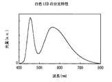
図6は、一般的なハロゲンランプの分光特性を示している。図7は、一般的な白色LEDの分光特性を示している。なお、この図7は上記第2の方式による白色LEDの分光特性を示している。図8は、両者の比較のために、ハロゲンランプの分光特性と白色LEDの分光特性とを同時に示したものである。図8において実線はハロゲンランプの分光特性、破線は白色LEDの分光特性を示している。図6〜図8において、横軸は波長(nm)、縦軸は光量を示す。なお、縦軸は任意単位(arbitrary unit)とする。 FIG. 6 shows the spectral characteristics of a general halogen lamp. FIG. 7 shows the spectral characteristics of a general white LED. FIG. 7 shows the spectral characteristics of the white LED according to the second method. FIG. 8 simultaneously shows the spectral characteristics of a halogen lamp and the spectral characteristics of a white LED for comparison between the two. In FIG. 8, the solid line indicates the spectral characteristic of the halogen lamp, and the broken line indicates the spectral characteristic of the white LED. 6 to 8, the horizontal axis indicates the wavelength (nm) and the vertical axis indicates the amount of light. Note that the vertical axis is an arbitrary unit.
図6に示したように、ハロゲンランプは、可視光の中間波長領域(黄色領域)に発光ピークを有し、可視光の短波長領域(青色領域)および長波長領域(赤色領域)に行くに従い光量が徐々に低下するようなスペクトル分布を有する。これに対し、上記第2の方式による白色LEDの場合、青色LEDチップからの青色光と、その青色光を励起光とする黄色系の蛍光材料による発光光とを混合させる方式であるため、図7に示したように、黄色領域のほか、青色領域にも発光ピークを有している。その青色領域の発光ピーク部分が、図8に示したように、ハロゲンランプと白色LEDとにおけるスペクトル分布の主要な違いとなっている。このため、例えば、レンズの性能評価を行うための装置の光源を、単純にハロゲンランプから白色LEDに置き換えてしまうと、ハロゲンランプを光源として用いた場合に比べて青色の収差が目立って観測されてしまう。 As shown in FIG. 6, the halogen lamp has a light emission peak in the intermediate wavelength region (yellow region) of visible light, and goes toward the short wavelength region (blue region) and long wavelength region (red region) of visible light. It has a spectral distribution in which the amount of light gradually decreases. On the other hand, in the case of the white LED according to the second method, the blue light from the blue LED chip and the light emitted from the yellow fluorescent material using the blue light as excitation light are mixed. As shown in FIG. 7, in addition to the yellow region, the blue region also has a light emission peak. The emission peak portion in the blue region is the main difference in the spectral distribution between the halogen lamp and the white LED, as shown in FIG. For this reason, for example, if the light source of a device for evaluating the performance of a lens is simply replaced with a white LED from a halogen lamp, blue aberration is noticeably observed compared to the case where a halogen lamp is used as the light source. End up.
本発明はかかる問題点に鑑みてなされたもので、その目的は、ハロゲンランプに比べて低コストかつ低消費電力で、かつハロゲンランプと同等の分光特性を得ることができるようにした光源装置を提供することにある。 The present invention has been made in view of such a problem, and an object of the present invention is to provide a light source device that is low in cost and low in power consumption as compared with a halogen lamp and can obtain spectral characteristics equivalent to those of a halogen lamp. It is to provide.
本発明による光源装置は、青色領域に発光ピークを有する白色光を発する白色LEDと、白色LEDから発せられた白色光のうち青色領域の光を部分的に低減する光学フィルタとを備えたものである。 A light source device according to the present invention includes a white LED that emits white light having a light emission peak in a blue region, and an optical filter that partially reduces light in the blue region of white light emitted from the white LED. is there.
本発明による光源装置では、白色LEDから、青色領域に発光ピークを有する白色光が発せられる。光学フィルタは、その白色光のうち青色領域の光を部分的に低減する。これにより、白色LEDから発せられた白色光の分光特性が、ハロゲンランプの分光特性に近づく。 In the light source device according to the present invention, white light having a light emission peak in the blue region is emitted from the white LED. The optical filter partially reduces light in the blue region of the white light. Thereby, the spectral characteristic of the white light emitted from the white LED approaches the spectral characteristic of the halogen lamp.
本発明による光源装置において、光学フィルタは、例えば、光源としての使用波長範囲内において、435nm以上465nm以下の波長範囲では透過率が5%以上20%以下、405nm以下および490nm以上の波長範囲では透過率が80%以上となるような分光透過率特性を有するものである。 In the light source device according to the present invention, the optical filter transmits, for example, in the wavelength range of 435 nm to 465 nm within the wavelength range used as the light source, and in the wavelength range of 5% to 20%, 405 nm, and 490 nm. It has spectral transmittance characteristics such that the rate is 80% or more.
本発明による光源装置において、白色LEDとしては例えば、青色光を発する青色LEDチップと、青色LEDチップからの青色光によって励起されて黄色光を発する蛍光材料とを有し、青色LEDチップからの青色光と蛍光材料による黄色光とを混合させることにより、白色光を発するものを使用することができる。 In the light source device according to the present invention, the white LED includes, for example, a blue LED chip that emits blue light and a fluorescent material that emits yellow light when excited by the blue light from the blue LED chip. By mixing light and yellow light by a fluorescent material, a material that emits white light can be used.
本発明の光源装置によれば、光源として白色LEDを用いるようにしたので、ハロゲンランプを用いる場合に比べて低コストかつ低消費電力を実現できる。また、白色LEDから発せられた白色光の分光特性がハロゲンランプの分光特性に近づくよう、光学フィルタによって青色領域の光を部分的に低減するようにしたので、ハロゲンランプと同等の分光特性を得ることができる。 According to the light source device of the present invention, since the white LED is used as the light source, lower cost and lower power consumption can be realized as compared with the case of using a halogen lamp. In addition, since the light in the blue region is partially reduced by the optical filter so that the spectral characteristics of white light emitted from the white LED approximate the spectral characteristics of the halogen lamp, the spectral characteristics equivalent to those of the halogen lamp are obtained. be able to.
以下、本発明の実施の形態について図面を参照して詳細に説明する。
図1は、本発明の一実施の形態に係る光源装置の一構成例を示している。この光源装置は、白色LED1と、光学フィルタ2とを備えている。白色LED1は、図7に示したような、青色領域に発光ピークを有する白色光23を発するものである。Hereinafter, embodiments of the present invention will be described in detail with reference to the drawings.
FIG. 1 shows a configuration example of a light source device according to an embodiment of the present invention. The light source device includes a
白色LED1は、青色光21を発する青色LEDチップ11と、青色LEDチップ11からの青色光21によって励起されて黄色光22を発する蛍光材料13とを有している。白色LED1は、青色LEDチップ11からの青色光21と蛍光材料13による黄色光22とを混合させることにより、白色光23を発するものである。青色LEDチップ11は、例えばGaN(窒化ガリウム)系の半導体材料よりなる発光素子である。青色LEDチップ11は、透明な樹脂モールド12でモールドされている。樹脂モールド12中に、蛍光材料13として、青色光21を励起光とする蛍光顔料や蛍光染料が分散されている。 The
光学フィルタ2は、白色LED1から発せられた白色光23のうち青色領域の光を部分的に低減し、その青色領域の光が低減された白色光24を出射するものである。光学フィルタ2は、例えば板状の透明基板に光学薄膜を形成したものである。 The
図2は、光学フィルタ2の分光透過率特性の一例を示している。図3は、図2に示した分光透過率特性を実現するための光学膜の設計例を示している。この設計例では、光学フィルタ2の基板の屈折率を、1.52にしている。ただし、膜物質、層数および各層の膜厚等はこれらの設計例に限定されるものではない。 FIG. 2 shows an example of the spectral transmittance characteristic of the
この光源装置では、白色LED1から、青色領域に発光ピークを有する白色光23が発せられる。光学フィルタ2は、その白色光23のうち青色領域の光を部分的に低減する。これにより、ハロゲンランプの分光特性に近い白色光24が得られる。 In this light source device,
ここで、図4を参照して、光学フィルタ2が満たすべき特性の条件を説明する。本実施の形態に係る光源装置は、白色LED1を用いながらも、最終的に出射される白色光24の分光特性が、ハロゲンランプの分光特性に近いことを特徴としている。既に図6〜図8を用いて説明したように、白色LED1における青色領域の発光ピーク部分が、ハロゲンランプと白色LED1とにおけるスペクトル分布の主要な違いとなっている。このため、光学フィルタ2は、ハロゲンランプとの違いである青色領域の発光ピーク部分の光量を低減するような特性を有している必要がある。この際、図8に示したように、白色LED1とハロゲンランプとでは青色領域以外のスペクトル分布にはあまり差はないので、青色領域以外では光学フィルタ2は白色LED1からの光をほぼそのまま透過する特性を有していることが好ましい。また、青色領域内であっても、完全に透過率をゼロにするのではなく、ある程度の光を透過する特性を有していることが好ましい。 Here, with reference to FIG. 4, conditions of characteristics to be satisfied by the
具体的には、図4に示したように、光学フィルタ2は、光源としての使用波長範囲内において、青色領域の特定の波長範囲λ1(例えば435nm以上465nm以下)では透過率が所定の範囲T1(例えば5%以上20%以下)となるような分光透過率特性を有していることが好ましい。また、光源としての使用波長範囲内において、特定の波長範囲λ1よりも短い波長領域λ2(例えば405nm以下)と、長い波長領域λ3(例えば490nm以上)とでは、透過率が所定の値T2以上(例えば80%以上)となるような分光透過率特性を有していることが好ましい。 Specifically, as shown in FIG. 4, the
図5は、ハロゲンランプの分光特性(実線で示す)と、本実施の形態に係る光源装置による最終的な出力光(白色光24)の分光特性(破線で示す)とを示している。図5に破線で示した特性は、白色LED1の特性を図7に示した特性とし、光学フィルタ2の特性を図2に示した特性とした場合に得られるものである。なお、図5において縦軸は任意単位(arbitrary unit)での光量を示すが、図5ではハロゲンランプと本実施の形態に係る光源装置との2つの光源の相対光量を、それぞれの最大値を1に規格化して表している。図5に示したように、本実施の形態に係る光源装置では、最終的な出力光としてハロゲンランプとほぼ同じ特性の光が得られている。 FIG. 5 shows the spectral characteristics (shown by solid lines) of the halogen lamp and the spectral characteristics (shown by broken lines) of the final output light (white light 24) from the light source device according to the present embodiment. The characteristic indicated by the broken line in FIG. 5 is obtained when the characteristic of the
以上説明したように、本実施の形態に係る光源装置によれば、光源として白色LED1を用いるようにしたので、ハロゲンランプを用いる場合に比べて低コストかつ低消費電力を実現できる。本実施の形態に係る光源装置によれば、ハロゲンランプを用いた場合に比べて消費電力を格段に下げることができるので、ランニングコストを下げることができる。また、白色LED1から発せられた白色光23の分光特性がハロゲンランプの分光特性に近づくよう、光学フィルタ2によって青色領域の光を部分的に低減するようにしたので、最終的な出力光(白色光24)として、ハロゲンランプと同等の分光特性を得ることができる。これにより、例えば、従来ハロゲンランプが用いられてきた測定機器の光源として、光学的な性能変化を気にすることなく、本実施の形態に係る光源装置を用いることができる。 As described above, according to the light source device according to the present embodiment, since the
1…白色LED、2…光学フィルタ、11…青色LEDチップ、12…樹脂モールド、13…蛍光材料、21…青色光、22…黄色光、23…青色領域に発光ピークを有する白色光、24…青色領域の光が低減された白色光。 DESCRIPTION OF
Claims (3)
Translated fromJapanese前記白色LEDから発せられた白色光のうち前記青色領域の光を部分的に低減する光学フィルタと
を備えたことを特徴とする光源装置。A white LED emitting white light having an emission peak in the blue region;
An optical filter for partially reducing the light in the blue region of the white light emitted from the white LED.
435nm以上465nm以下の波長範囲では透過率が5%以上20%以下、
405nm以下および490nm以上の波長範囲では透過率が80%以上、
となるような分光透過率特性を有する
ことを特徴とする請求項1に記載の光源装置。The optical filter is used within a wavelength range used as a light source.
In the wavelength range of 435 nm to 465 nm, the transmittance is 5% to 20%,
In the wavelength range of 405 nm or less and 490 nm or more, the transmittance is 80% or more,
The light source device according to claim 1, wherein the light source device has a spectral transmittance characteristic as follows.
青色光を発する青色LEDチップと、前記青色LEDチップからの青色光によって励起されて黄色光を発する蛍光材料とを有し、前記青色LEDチップからの青色光と前記蛍光材料による黄色光とを混合させることにより、前記白色光を発するものである
ことを特徴とする請求項1または2に記載の光源装置。The white LED is
A blue LED chip that emits blue light and a fluorescent material that emits yellow light when excited by blue light from the blue LED chip, and mixes blue light from the blue LED chip and yellow light from the fluorescent material The light source device according to claim 1, wherein the light source device emits the white light.
Priority Applications (3)
| Application Number | Priority Date | Filing Date | Title |
|---|---|---|---|
| JP2008257058AJP2010087393A (en) | 2008-10-02 | 2008-10-02 | Light source device |
| EP09010468AEP2172794A1 (en) | 2008-10-02 | 2009-08-13 | Light source device |
| US12/541,684US8182115B2 (en) | 2008-10-02 | 2009-08-14 | Light source device |
Applications Claiming Priority (1)
| Application Number | Priority Date | Filing Date | Title |
|---|---|---|---|
| JP2008257058AJP2010087393A (en) | 2008-10-02 | 2008-10-02 | Light source device |
Publications (1)
| Publication Number | Publication Date |
|---|---|
| JP2010087393Atrue JP2010087393A (en) | 2010-04-15 |
Family
ID=41491622
Family Applications (1)
| Application Number | Title | Priority Date | Filing Date |
|---|---|---|---|
| JP2008257058AAbandonedJP2010087393A (en) | 2008-10-02 | 2008-10-02 | Light source device |
Country Status (3)
| Country | Link |
|---|---|
| US (1) | US8182115B2 (en) |
| EP (1) | EP2172794A1 (en) |
| JP (1) | JP2010087393A (en) |
Cited By (3)
| Publication number | Priority date | Publication date | Assignee | Title |
|---|---|---|---|---|
| JP2012160432A (en)* | 2011-02-01 | 2012-08-23 | Silitek Electronic (Guangzhou) Co Ltd | Illumination device, and method of selecting color of toner for mediation layer thereof |
| KR101244921B1 (en) | 2010-08-23 | 2013-03-18 | 피에스아이 주식회사 | White LED device using multi-chip |
| WO2015023020A1 (en)* | 2013-08-12 | 2015-02-19 | Cho Shim Hyun | Color temperature conversion filter for light emitting diode, light emitting diode module, and lighting device comprising same |
Families Citing this family (40)
| Publication number | Priority date | Publication date | Assignee | Title |
|---|---|---|---|---|
| US9681522B2 (en) | 2012-05-06 | 2017-06-13 | Lighting Science Group Corporation | Adaptive light system and associated methods |
| US8324808B2 (en)* | 2010-07-23 | 2012-12-04 | Biological Illumination, Llc | LED lamp for producing biologically-corrected light |
| US8760370B2 (en) | 2011-05-15 | 2014-06-24 | Lighting Science Group Corporation | System for generating non-homogenous light and associated methods |
| US9024536B2 (en) | 2011-12-05 | 2015-05-05 | Biological Illumination, Llc | Tunable LED lamp for producing biologically-adjusted light and associated methods |
| US8253336B2 (en) | 2010-07-23 | 2012-08-28 | Biological Illumination, Llc | LED lamp for producing biologically-corrected light |
| US8743023B2 (en) | 2010-07-23 | 2014-06-03 | Biological Illumination, Llc | System for generating non-homogenous biologically-adjusted light and associated methods |
| US9827439B2 (en) | 2010-07-23 | 2017-11-28 | Biological Illumination, Llc | System for dynamically adjusting circadian rhythm responsive to scheduled events and associated methods |
| US8841864B2 (en) | 2011-12-05 | 2014-09-23 | Biological Illumination, Llc | Tunable LED lamp for producing biologically-adjusted light |
| US9532423B2 (en) | 2010-07-23 | 2016-12-27 | Lighting Science Group Corporation | System and methods for operating a lighting device |
| US8686641B2 (en) | 2011-12-05 | 2014-04-01 | Biological Illumination, Llc | Tunable LED lamp for producing biologically-adjusted light |
| US8401231B2 (en) | 2010-11-09 | 2013-03-19 | Biological Illumination, Llc | Sustainable outdoor lighting system for use in environmentally photo-sensitive area |
| US8754832B2 (en) | 2011-05-15 | 2014-06-17 | Lighting Science Group Corporation | Lighting system for accenting regions of a layer and associated methods |
| US9173269B2 (en) | 2011-05-15 | 2015-10-27 | Lighting Science Group Corporation | Lighting system for accentuating regions of a layer and associated methods |
| US8901850B2 (en) | 2012-05-06 | 2014-12-02 | Lighting Science Group Corporation | Adaptive anti-glare light system and associated methods |
| CN102401920A (en)* | 2011-07-12 | 2012-04-04 | 苏州昆仑工业设计有限公司 | Coated optical filter for reducing harm of LED blue light |
| CN102392976A (en)* | 2011-07-12 | 2012-03-28 | 苏州昆仑工业设计有限公司 | LED (light emitting diode) organic material filter |
| CN102392975A (en)* | 2011-07-12 | 2012-03-28 | 苏州昆仑工业设计有限公司 | Composite filter for LED (Light-Emitting Diode) |
| CN102401918B (en)* | 2011-07-12 | 2013-11-06 | 苏州昆仑工业设计有限公司 | LED coated filter |
| CN102401326A (en)* | 2011-07-12 | 2012-04-04 | 苏州昆仑工业设计有限公司 | Doped optical filter for improving color rendering of LED |
| CN102392977A (en)* | 2011-07-12 | 2012-03-28 | 苏州昆仑工业设计有限公司 | Film-coated filter for improving LED (light emitting diode) color rendering |
| JP2013037788A (en)* | 2011-08-03 | 2013-02-21 | Opt Design:Kk | Surface illumination light source device using illuminant |
| US8963450B2 (en) | 2011-12-05 | 2015-02-24 | Biological Illumination, Llc | Adaptable biologically-adjusted indirect lighting device and associated methods |
| US9913341B2 (en) | 2011-12-05 | 2018-03-06 | Biological Illumination, Llc | LED lamp for producing biologically-adjusted light including a cyan LED |
| US8866414B2 (en) | 2011-12-05 | 2014-10-21 | Biological Illumination, Llc | Tunable LED lamp for producing biologically-adjusted light |
| US9289574B2 (en) | 2011-12-05 | 2016-03-22 | Biological Illumination, Llc | Three-channel tuned LED lamp for producing biologically-adjusted light |
| US9220202B2 (en) | 2011-12-05 | 2015-12-29 | Biological Illumination, Llc | Lighting system to control the circadian rhythm of agricultural products and associated methods |
| FR2988808B1 (en)* | 2012-03-27 | 2014-03-21 | Maquet Sas | WHITE LED LIGHTING DEVICE, LIGHTING APPARATUS |
| US9402294B2 (en) | 2012-05-08 | 2016-07-26 | Lighting Science Group Corporation | Self-calibrating multi-directional security luminaire and associated methods |
| US9006987B2 (en) | 2012-05-07 | 2015-04-14 | Lighting Science Group, Inc. | Wall-mountable luminaire and associated systems and methods |
| US8680457B2 (en) | 2012-05-07 | 2014-03-25 | Lighting Science Group Corporation | Motion detection system and associated methods having at least one LED of second set of LEDs to vary its voltage |
| US9174067B2 (en) | 2012-10-15 | 2015-11-03 | Biological Illumination, Llc | System for treating light treatable conditions and associated methods |
| JP6322939B2 (en)* | 2012-12-03 | 2018-05-16 | 株式会社リコー | Imaging system and color inspection system |
| CN103022328B (en)* | 2013-01-17 | 2016-06-01 | 中国科学院上海高等研究院 | Solar simulator light source and its implementation |
| US9347655B2 (en) | 2013-03-11 | 2016-05-24 | Lighting Science Group Corporation | Rotatable lighting device |
| US20140268731A1 (en) | 2013-03-15 | 2014-09-18 | Lighting Science Group Corpporation | Low bay lighting system and associated methods |
| CN103574367A (en)* | 2013-11-12 | 2014-02-12 | 中国人民解放军63960部队 | High dynamic white light LED optical radiation simulator |
| CN108931716B (en)* | 2017-05-23 | 2020-09-18 | 光焱科技股份有限公司 | Measuring equipment for solar cells |
| CN109411590B (en)* | 2017-08-17 | 2020-01-07 | 光宝光电(常州)有限公司 | Light-emitting diode structure and light-emitting unit |
| EP3457444A1 (en)* | 2017-09-19 | 2019-03-20 | ams AG | Phosphor-converted light-emitting device |
| KR20240124739A (en)* | 2023-02-09 | 2024-08-19 | 삼성전자주식회사 | Light emitting devices |
Citations (7)
| Publication number | Priority date | Publication date | Assignee | Title |
|---|---|---|---|---|
| WO2001001070A1 (en)* | 1999-06-29 | 2001-01-04 | Omron Corporation | Light source device, spectroscope comprising the light source device, and film thickness sensor |
| JP2001041888A (en)* | 1999-07-02 | 2001-02-16 | Byk Gardner Gmbh | Device and method for determining surface quality |
| JP2003152227A (en)* | 2001-11-14 | 2003-05-23 | Citizen Electronics Co Ltd | LED color correction means and color correction method |
| JP2006236749A (en)* | 2005-02-24 | 2006-09-07 | Puraruto:Kk | Light source device and display device |
| JP2007234877A (en)* | 2006-03-01 | 2007-09-13 | Nichia Chem Ind Ltd | Light emitting device |
| JP2007311114A (en)* | 2006-05-17 | 2007-11-29 | Olympus Corp | Lighting optical system using solid light emitting element emitting white light, and optical device equipped with it |
| WO2008103876A1 (en)* | 2007-02-22 | 2008-08-28 | Cree Led Lighting Solutions, Inc. | Lighting devices, methods of lighting, light filters and methods of filtering light |
Family Cites Families (7)
| Publication number | Priority date | Publication date | Assignee | Title |
|---|---|---|---|---|
| US4047805A (en)* | 1973-02-14 | 1977-09-13 | Canon Kabushiki Kaisha | Ripple-free dichroic mirrors |
| US5962971A (en)* | 1997-08-29 | 1999-10-05 | Chen; Hsing | LED structure with ultraviolet-light emission chip and multilayered resins to generate various colored lights |
| JP4136126B2 (en) | 1998-10-29 | 2008-08-20 | 株式会社ワコム電創 | Simulated solar irradiation lamp automatic changer |
| US6417019B1 (en)* | 2001-04-04 | 2002-07-09 | Lumileds Lighting, U.S., Llc | Phosphor converted light emitting diode |
| JP3912228B2 (en) | 2002-08-30 | 2007-05-09 | 株式会社島津製作所 | Light source for analysis and measurement |
| US20050127833A1 (en)* | 2003-12-10 | 2005-06-16 | Tieszen Dwayne A. | White light LED and method to adjust the color output of same |
| DE102007056562A1 (en) | 2007-11-23 | 2009-05-28 | Oerlikon Textile Gmbh & Co. Kg | Device for the optical detection of contaminants in longitudinally moved yarn |
- 2008
- 2008-10-02JPJP2008257058Apatent/JP2010087393A/ennot_activeAbandoned
- 2009
- 2009-08-13EPEP09010468Apatent/EP2172794A1/ennot_activeWithdrawn
- 2009-08-14USUS12/541,684patent/US8182115B2/enactiveActive
Patent Citations (7)
| Publication number | Priority date | Publication date | Assignee | Title |
|---|---|---|---|---|
| WO2001001070A1 (en)* | 1999-06-29 | 2001-01-04 | Omron Corporation | Light source device, spectroscope comprising the light source device, and film thickness sensor |
| JP2001041888A (en)* | 1999-07-02 | 2001-02-16 | Byk Gardner Gmbh | Device and method for determining surface quality |
| JP2003152227A (en)* | 2001-11-14 | 2003-05-23 | Citizen Electronics Co Ltd | LED color correction means and color correction method |
| JP2006236749A (en)* | 2005-02-24 | 2006-09-07 | Puraruto:Kk | Light source device and display device |
| JP2007234877A (en)* | 2006-03-01 | 2007-09-13 | Nichia Chem Ind Ltd | Light emitting device |
| JP2007311114A (en)* | 2006-05-17 | 2007-11-29 | Olympus Corp | Lighting optical system using solid light emitting element emitting white light, and optical device equipped with it |
| WO2008103876A1 (en)* | 2007-02-22 | 2008-08-28 | Cree Led Lighting Solutions, Inc. | Lighting devices, methods of lighting, light filters and methods of filtering light |
Cited By (4)
| Publication number | Priority date | Publication date | Assignee | Title |
|---|---|---|---|---|
| KR101244921B1 (en) | 2010-08-23 | 2013-03-18 | 피에스아이 주식회사 | White LED device using multi-chip |
| JP2012160432A (en)* | 2011-02-01 | 2012-08-23 | Silitek Electronic (Guangzhou) Co Ltd | Illumination device, and method of selecting color of toner for mediation layer thereof |
| KR101354715B1 (en)* | 2011-02-01 | 2014-01-24 | 라이트온 테크놀러지 코포레이션 | Lighting device and method for selecting toner color of a medium layer thereof |
| WO2015023020A1 (en)* | 2013-08-12 | 2015-02-19 | Cho Shim Hyun | Color temperature conversion filter for light emitting diode, light emitting diode module, and lighting device comprising same |
Also Published As
| Publication number | Publication date |
|---|---|
| US8182115B2 (en) | 2012-05-22 |
| EP2172794A1 (en) | 2010-04-07 |
| US20100085758A1 (en) | 2010-04-08 |
Similar Documents
| Publication | Publication Date | Title |
|---|---|---|
| JP2010087393A (en) | Light source device | |
| JP5382849B2 (en) | Light source device | |
| CN106068675B (en) | Lamps for enhanced optical illumination and color preference | |
| TW480744B (en) | Light-emitting diode, lighting device and method of manufacturing same | |
| EP3001467A1 (en) | Light-emitting module | |
| US20100001299A1 (en) | Light emitting diode illuminating apparatus with same-type light emitting diodes | |
| US20140167599A1 (en) | Light-emitting module and lighting source including the same | |
| KR100771811B1 (en) | White light emitting device | |
| US9431587B2 (en) | LED light system | |
| WO2016049955A1 (en) | Light-emitting module | |
| US9488333B2 (en) | Lighting device | |
| TWI610457B (en) | White light source device | |
| US20140252391A1 (en) | Light-emitting device | |
| RU2651794C2 (en) | Dimable light emitting arrangement | |
| TW200908368A (en) | White light LED | |
| JP2019533880A (en) | Lighting device comprising a plurality of different light sources having similar off-state appearance | |
| JP4233466B2 (en) | LIGHT EMITTING DEVICE, LIGHTING DEVICE, AND DISPLAY DEVICE | |
| CN103124875B (en) | Lighting system with increased efficiency | |
| JP2008227490A (en) | Illuminating module particularly for surgical microscope | |
| JP7452086B2 (en) | light emitting device | |
| JP2007109837A (en) | Lighting apparatus | |
| JP2013511828A (en) | Light emitting device | |
| TW201724489A (en) | LED module, LED array module and display module with excellent color purity | |
| US10240726B2 (en) | Luminaire and method of manufacturing luminaire | |
| JP7519017B2 (en) | Light-emitting device |
Legal Events
| Date | Code | Title | Description |
|---|---|---|---|
| A711 | Notification of change in applicant | Free format text:JAPANESE INTERMEDIATE CODE: A711 Effective date:20100621 | |
| A621 | Written request for application examination | Free format text:JAPANESE INTERMEDIATE CODE: A621 Effective date:20110708 | |
| RD03 | Notification of appointment of power of attorney | Free format text:JAPANESE INTERMEDIATE CODE: A7423 Effective date:20110805 | |
| RD04 | Notification of resignation of power of attorney | Free format text:JAPANESE INTERMEDIATE CODE: A7424 Effective date:20111216 | |
| RD03 | Notification of appointment of power of attorney | Free format text:JAPANESE INTERMEDIATE CODE: A7423 Effective date:20120914 | |
| A977 | Report on retrieval | Free format text:JAPANESE INTERMEDIATE CODE: A971007 Effective date:20120919 | |
| A131 | Notification of reasons for refusal | Free format text:JAPANESE INTERMEDIATE CODE: A131 Effective date:20121002 | |
| RD04 | Notification of resignation of power of attorney | Free format text:JAPANESE INTERMEDIATE CODE: A7424 Effective date:20121004 | |
| A762 | Written abandonment of application | Free format text:JAPANESE INTERMEDIATE CODE: A762 Effective date:20121120 |