JP2010082040A - Endoscope system - Google Patents
Endoscope systemDownload PDFInfo
- Publication number
- JP2010082040A JP2010082040AJP2008252343AJP2008252343AJP2010082040AJP 2010082040 AJP2010082040 AJP 2010082040AJP 2008252343 AJP2008252343 AJP 2008252343AJP 2008252343 AJP2008252343 AJP 2008252343AJP 2010082040 AJP2010082040 AJP 2010082040A
- Authority
- JP
- Japan
- Prior art keywords
- light
- imaging device
- imaging
- endoscope
- emitted
- Prior art date
- Legal status (The legal status is an assumption and is not a legal conclusion. Google has not performed a legal analysis and makes no representation as to the accuracy of the status listed.)
- Abandoned
Links
Images


Classifications
- A—HUMAN NECESSITIES
- A61—MEDICAL OR VETERINARY SCIENCE; HYGIENE
- A61B—DIAGNOSIS; SURGERY; IDENTIFICATION
- A61B1/00—Instruments for performing medical examinations of the interior of cavities or tubes of the body by visual or photographical inspection, e.g. endoscopes; Illuminating arrangements therefor
- A61B1/04—Instruments for performing medical examinations of the interior of cavities or tubes of the body by visual or photographical inspection, e.g. endoscopes; Illuminating arrangements therefor combined with photographic or television appliances
- A61B1/043—Instruments for performing medical examinations of the interior of cavities or tubes of the body by visual or photographical inspection, e.g. endoscopes; Illuminating arrangements therefor combined with photographic or television appliances for fluorescence imaging
- A—HUMAN NECESSITIES
- A61—MEDICAL OR VETERINARY SCIENCE; HYGIENE
- A61B—DIAGNOSIS; SURGERY; IDENTIFICATION
- A61B1/00—Instruments for performing medical examinations of the interior of cavities or tubes of the body by visual or photographical inspection, e.g. endoscopes; Illuminating arrangements therefor
- A61B1/00064—Constructional details of the endoscope body
- A61B1/00071—Insertion part of the endoscope body
- A61B1/0008—Insertion part of the endoscope body characterised by distal tip features
- A61B1/00096—Optical elements
- A—HUMAN NECESSITIES
- A61—MEDICAL OR VETERINARY SCIENCE; HYGIENE
- A61B—DIAGNOSIS; SURGERY; IDENTIFICATION
- A61B1/00—Instruments for performing medical examinations of the interior of cavities or tubes of the body by visual or photographical inspection, e.g. endoscopes; Illuminating arrangements therefor
- A61B1/04—Instruments for performing medical examinations of the interior of cavities or tubes of the body by visual or photographical inspection, e.g. endoscopes; Illuminating arrangements therefor combined with photographic or television appliances
- A61B1/05—Instruments for performing medical examinations of the interior of cavities or tubes of the body by visual or photographical inspection, e.g. endoscopes; Illuminating arrangements therefor combined with photographic or television appliances characterised by the image sensor, e.g. camera, being in the distal end portion
- A61B1/051—Details of CCD assembly
- A—HUMAN NECESSITIES
- A61—MEDICAL OR VETERINARY SCIENCE; HYGIENE
- A61B—DIAGNOSIS; SURGERY; IDENTIFICATION
- A61B1/00—Instruments for performing medical examinations of the interior of cavities or tubes of the body by visual or photographical inspection, e.g. endoscopes; Illuminating arrangements therefor
- A61B1/06—Instruments for performing medical examinations of the interior of cavities or tubes of the body by visual or photographical inspection, e.g. endoscopes; Illuminating arrangements therefor with illuminating arrangements
- A61B1/0638—Instruments for performing medical examinations of the interior of cavities or tubes of the body by visual or photographical inspection, e.g. endoscopes; Illuminating arrangements therefor with illuminating arrangements providing two or more wavelengths
- A—HUMAN NECESSITIES
- A61—MEDICAL OR VETERINARY SCIENCE; HYGIENE
- A61B—DIAGNOSIS; SURGERY; IDENTIFICATION
- A61B5/00—Measuring for diagnostic purposes; Identification of persons
- A61B5/0059—Measuring for diagnostic purposes; Identification of persons using light, e.g. diagnosis by transillumination, diascopy, fluorescence
- A61B5/0071—Measuring for diagnostic purposes; Identification of persons using light, e.g. diagnosis by transillumination, diascopy, fluorescence by measuring fluorescence emission
- A—HUMAN NECESSITIES
- A61—MEDICAL OR VETERINARY SCIENCE; HYGIENE
- A61B—DIAGNOSIS; SURGERY; IDENTIFICATION
- A61B5/00—Measuring for diagnostic purposes; Identification of persons
- A61B5/0059—Measuring for diagnostic purposes; Identification of persons using light, e.g. diagnosis by transillumination, diascopy, fluorescence
- A61B5/0082—Measuring for diagnostic purposes; Identification of persons using light, e.g. diagnosis by transillumination, diascopy, fluorescence adapted for particular medical purposes
- A61B5/0084—Measuring for diagnostic purposes; Identification of persons using light, e.g. diagnosis by transillumination, diascopy, fluorescence adapted for particular medical purposes for introduction into the body, e.g. by catheters
Landscapes
- Health & Medical Sciences (AREA)
- Life Sciences & Earth Sciences (AREA)
- Surgery (AREA)
- Medical Informatics (AREA)
- Biophysics (AREA)
- Engineering & Computer Science (AREA)
- Biomedical Technology (AREA)
- Heart & Thoracic Surgery (AREA)
- Physics & Mathematics (AREA)
- Molecular Biology (AREA)
- Pathology (AREA)
- Animal Behavior & Ethology (AREA)
- General Health & Medical Sciences (AREA)
- Public Health (AREA)
- Veterinary Medicine (AREA)
- Nuclear Medicine, Radiotherapy & Molecular Imaging (AREA)
- Optics & Photonics (AREA)
- Radiology & Medical Imaging (AREA)
- Endoscopes (AREA)
Abstract
Translated fromJapaneseDescription
Translated fromJapanese本発明は、内視鏡システムに係り、特に、人及び動物の内視鏡(硬性鏡、軟性鏡)による診断や治療(手術)において、可視光による通常の内視鏡観察における通常撮像と、赤外光等を用いた特殊光観察における蛍光撮像との両方を行う内視鏡システムに関する。 The present invention relates to an endoscope system, and in particular, normal imaging in normal endoscopic observation with visible light in diagnosis and treatment (surgery) with human and animal endoscopes (rigid and flexible endoscopes); The present invention relates to an endoscope system that performs both fluorescence imaging in special light observation using infrared light or the like.
従来より、医療分野において内視鏡装置(内視鏡システム)が広く用いられている。内視鏡装置は、体腔内に細長い挿入部を挿入して、体腔内の臓器等の観察対象を観察したり、挿入部に設けられた穴(鉗子口)から処置具を挿入して各種治療を行ったりするものである。 Conventionally, endoscope apparatuses (endoscope systems) have been widely used in the medical field. An endoscopic device inserts a long and thin insertion portion into a body cavity to observe an observation target such as an organ in the body cavity, or inserts a treatment tool from a hole (forceps opening) provided in the insertion portion to perform various treatments. Or something to do.
内視鏡装置では、体腔内に挿入して観察対象を観察するために観察対象を照射する照明手段が必要である。このとき照明光源として通常の白色光源を用いると、観察対象の表面でのみ反射してしまい、下層に存在する血管等を観察することは困難であった。 In an endoscope apparatus, an illuminating unit that irradiates an observation object is necessary to insert the object into a body cavity and observe the observation object. At this time, if a normal white light source is used as the illumination light source, it is reflected only on the surface of the observation target, and it is difficult to observe blood vessels and the like existing in the lower layer.
そこで近年、可視光を用いた通常の内視鏡観察に対して紫外光や近赤外光などの特殊光を用いた特殊光観察を行う内視鏡が用いられるようになっている。このような内視鏡によれば、近赤外光を用いて観察対象を照射することにより、観察対象の表面よりも下層の状態を観察することができる。 Therefore, in recent years, endoscopes that perform special light observation using special light such as ultraviolet light or near infrared light have been used for normal endoscope observation using visible light. According to such an endoscope, the state below the surface of the observation object can be observed by irradiating the observation object with near infrared light.
例えば、透過率特性可変素子(エタロン素子)を用いて生体組織からの反射光の波長帯域を切り換えて可視光と蛍光を分光することにより、反射光の異なる波長域に対する画像情報を得るようにした分光画像観察用光学装置が知られている(例えば、特許文献1等参照)。
しかしながら、可視光による通常撮像と蛍光撮像の両方を実現しようとした場合に、例えば上記特許文献1に記載のものではエタロン素子という特殊な装置を必要とし、また、可視光と蛍光のそれぞれについて別の撮像デバイスを配置しようとすると、内視鏡の先端の前面にこれら複数の撮像デバイスを並列配置する必要があり、内視鏡を細径化することが困難であるという問題がある。 However, when trying to realize both normal imaging and fluorescence imaging using visible light, for example, the device described in Patent Document 1 requires a special device called an etalon element, and separates each of visible light and fluorescence. When it is going to arrange | position this imaging device, it is necessary to arrange these several imaging devices in parallel at the front surface of the front-end | tip of an endoscope, and there exists a problem that it is difficult to reduce an endoscope in diameter.
本発明は、このような事情に鑑みてなされたもので、内視鏡(硬性鏡、軟性鏡)の細径を維持し、かつ可視光による通常撮像と蛍光撮像の両立を図ることを可能とした内視鏡システムを提供することを目的とする。 The present invention has been made in view of such circumstances, and can maintain the small diameter of an endoscope (rigid endoscope, flexible endoscope) and can achieve both normal imaging using visible light and fluorescence imaging. An object of the present invention is to provide an endoscope system.
前記目的を達成するために、請求項1に記載の発明は、体腔内に挿入され生体観察部を観察するための内視鏡スコープと、前記生体観察部を照明する照明光を出射する光源と、前記内視鏡スコープで検出した信号に対して信号処理を行い画像を生成するプロセサと、前記プロセサで生成された画像を表示するモニタとを備えた内視鏡システムであって、前記内視鏡スコープの先端部に、前記生体観察部で反射された前記照明光の反射光あるいは前記生体観察部で発せられた発光光を検出する複数の撮像装置が直列に配列され、前記複数の撮像装置の各々は、前記反射光あるいは前記発光光の一部を90°屈曲させると共に前記反射光あるいは前記発光光の一部を透過させる光分割手段と該90°屈曲された前記反射光あるいは前記発光光を検出する撮像デバイスとを有すると共に、最も後段の撮像装置は、前記反射光あるいは前記発光光を90°屈曲させる光路変更手段と該90°屈曲された前記反射光あるいは前記発光光を検出する撮像デバイスとから成り、前記光分割手段及び前記光路変更手段が直列に配置された観察光学部材が設けられたことを特徴とする内視鏡システムを提供する。 In order to achieve the object, the invention according to claim 1 is an endoscope that is inserted into a body cavity to observe a living body observation unit, and a light source that emits illumination light that illuminates the living body observation unit. An endoscope system comprising: a processor that performs signal processing on a signal detected by the endoscope scope to generate an image; and a monitor that displays the image generated by the processor. A plurality of imaging devices that detect the reflected light of the illumination light reflected by the living body observation unit or the emitted light emitted from the living body observation unit are arranged in series at the tip of a mirror scope, and the plurality of imaging devices Each of the reflected light or a part of the emitted light bends by 90 ° and transmits the reflected light or a part of the emitted light, and the reflected light or emitted light bent by 90 °. Detect The imaging device at the rearmost stage includes an optical path changing unit that bends the reflected light or the emitted light by 90 °, and an imaging device that detects the reflected light or the emitted light bent by 90 °. The endoscope system is characterized in that an observation optical member in which the light dividing means and the optical path changing means are arranged in series is provided.
このように、複数の撮像装置を直列に配置することで内視鏡の細径を維持しながら異なる波長域での撮像を両立させることが可能となる。 Thus, by arranging a plurality of imaging devices in series, it is possible to achieve both imaging in different wavelength ranges while maintaining the small diameter of the endoscope.
また、請求項2に示すように、前記光源は、可視光を出射する可視光源と、近赤外光を出射する近赤外光源とを有し、前記直列に配列された撮像装置は2つであり、前段の撮像装置は近赤外光を90°屈曲させると共に可視光を透過させる光分割手段と近赤外域に主要な感度を持つ撮像デバイスを備え、後段の撮像装置は前段の撮像装置の光分割手段を透過した可視光を90°屈曲させる光路変更手段と可視光域に主要な感度を持つ撮像デバイスを備えたことを特徴とする。 According to a second aspect of the present invention, the light source includes a visible light source that emits visible light and a near-infrared light source that emits near-infrared light, and the two imaging devices arranged in series are two. The front-stage imaging device includes a light splitting unit that bends near-infrared light by 90 ° and transmits visible light, and an imaging device having main sensitivity in the near-infrared region, and the rear-stage imaging device is a front-stage imaging device. An optical path changing means for bending visible light transmitted through the light splitting means by 90 ° and an imaging device having main sensitivity in the visible light range are provided.
これにより、可視光による通常撮像と蛍光撮像の両立を実現することができ、さらに可視光と蛍光を別々の撮像デバイスで撮像することでそれぞれの感度を向上させることができる。 Thereby, it is possible to realize both normal imaging using fluorescent light and fluorescence imaging, and further, it is possible to improve the respective sensitivity by imaging visible light and fluorescence using separate imaging devices.
また、請求項3に示すように、前記前段の撮像装置の光分割手段はダイクロイックプリズムであることを特徴とする。 According to a third aspect of the present invention, the light splitting means of the imaging device in the preceding stage is a dichroic prism.
また、請求項4に示すように、前記前段の撮像装置の光分割手段と撮像デバイスとの間に近赤外光のみを抽出するフィルタを設けたことを特徴とする。
According to a fourth aspect of the present invention, a filter for extracting only near-infrared light is provided between the light splitting means and the imaging device of the preceding stage imaging apparatus.
また、請求項5に示すように、前記前段の撮像装置の光分割手段と、前記後段の撮像装置の光路変更手段との間に可視光のゲイン調整手段を備えたことを特徴とする。 According to a fifth aspect of the present invention, a visible light gain adjusting unit is provided between the light splitting unit of the preceding imaging device and the optical path changing unit of the succeeding imaging device.
これにより、蛍光の感度を向上させると共に、可視光による通常撮像も適切に行うことができる。 Thereby, the sensitivity of fluorescence can be improved, and normal imaging with visible light can be appropriately performed.
また、請求項6に示すように、前記複数の撮像装置のうち、最も前段に配置した撮像装置の撮像デバイスは、青色光の自家蛍光域に主要な感度を有することを特徴とする。 According to a sixth aspect of the present invention, the imaging device of the imaging device arranged in the foremost stage among the plurality of imaging devices has a main sensitivity in the autofluorescence region of blue light.
このように、様々な波長領域に感度を有する撮像デバイスを有する撮像装置を直列に配置することにより、内視鏡の細径を維持しつつ、様々な波長域での撮像が可能となる。 As described above, by arranging in series the imaging devices having imaging devices having sensitivity in various wavelength regions, it is possible to perform imaging in various wavelength regions while maintaining the small diameter of the endoscope.
以上説明したように、本発明によれば、撮像装置を直列に配置することで内視鏡の細径を維持しながら異なる波長域での撮像、特に可視光による通常撮像と蛍光撮像を両立させることが可能となる。 As described above, according to the present invention, by arranging the imaging devices in series, imaging in different wavelength ranges, particularly normal imaging by visible light and fluorescence imaging can be made compatible while maintaining the small diameter of the endoscope. It becomes possible.
以下、添付図面を参照して、本発明に係る内視鏡システムについて詳細に説明する。 Hereinafter, an endoscope system according to the present invention will be described in detail with reference to the accompanying drawings.
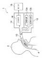
図1は、本発明の内視鏡システムの第1の実施形態の概略を示す構成図である。 FIG. 1 is a configuration diagram showing an outline of the first embodiment of the endoscope system of the present invention.
図1に示すように、本実施形態の内視鏡システム1は、患者2の体腔4内に挿入される撮像手段を内蔵した内視鏡スコープ10と、内視鏡スコープ10に照明光を供給する光源装置12と、内視鏡スコープ10の撮像手段からの信号の処理を行う信号処理装置14と、信号処理装置14から出力される画像信号(映像信号)に基づいて画像を表示するモニタ16とから構成される。 As shown in FIG. 1, the endoscope system 1 of the present embodiment supplies an
本実施形態の内視鏡スコープ10は、詳しくは後述するが、可視光による通常撮像と蛍光撮像の両立を実現するものである。そのため、光源装置12は、可視光源12aと近赤外光源12bの2種類の光源を備えている。 Although described in detail later, the
光源装置12としては、具体的には特に限定されるものではないが、例えば、可視光源12aとしてはキセノンランプ、近赤外光源12bとしては半導体レーザが好適に例示される。 The
信号処理装置14は、内視鏡スコープ10の撮像手段(CCD)からの信号を画像信号に変換し、所定の画像処理を施して出力するものであり、画像処理を行うプロセサ18を有している。 The
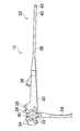
図2に内視鏡スコープ10を拡大して示す。 FIG. 2 shows an enlarged view of the
図2に示すように、内視鏡スコープ10には、主として、手元操作部20と、この手元操作部20に連設された挿入部22を備え、手元操作部20には、ユニバーサルケーブル24が接続される。ユニバーサルケーブル24の先端には、プロセサ18や光源装置12に接続されるコネクタ(図示省略)が設けられる。 As shown in FIG. 2, the
手元操作部20には、送気・送水ボタン26、吸引ボタン28、シャッターボタン30、ズーム操作用のシーソースイッチ32、アングルノブ34、34、及び鉗子挿入部36が設けられている。 The
また、挿入部22は、軟性部38、湾曲部40、及び先端部42で構成されている。湾曲部40は、手元操作部20に設けられた一対のアングルノブ34、34を回動することによって遠隔的に湾曲操作されるようになっている。これにより、先端部42の先端面を所望の方向に向けることができる。 The insertion portion 22 includes a
図3に、挿入部22の先端部42の先端面を示す。 FIG. 3 shows the distal end surface of the
図3に示すように、先端部42の先端面には、観察光学部材44、照明部材46、46、送気・送水ノズル48、鉗子チャンネル(鉗子口)50が配設されている。また、先端面にはキャップ52がネジ54によって固定され、装着されている。観察光学部材44は、先端面の略中央に配置され、この観察光学部材44の左右に照明部材46、46が配設されている。 As shown in FIG. 3, an observation
図4に、第1実施形態における内視鏡スコープ10の先端部42の縦断面図を示す。 FIG. 4 shows a longitudinal sectional view of the
図4に示すように、先端部42内には、観察光学部材44、照明部材46及び鉗子チャンネル(鉗子口)50が配設されている。 As shown in FIG. 4, an observation
照明部材46は、照明光を拡散させる光学系である照明レンズ56と、光源装置12から照明レンズ56へ照明光を伝送するライトガイド58とを備えている。これにより、光源装置12からの照明光は、ライトガイド58及び照明レンズ56を介して、先端部42の先端面のカバーガラスが嵌め込まれた照明窓60より射出されるようになっている。 The
なお、図4では、ライトガイド等は一つのみ表示されているが、実際には、可視光源12a及び近赤外光源12bそれぞれ対して一つずつ設けられている。 In FIG. 4, only one light guide or the like is displayed, but actually, one light guide is provided for each of the
観察光学部材44は、先端面側に固定レンズ62a、62b及び可動レンズ64を備えている。なお、図ではこれらのレンズはそれぞれ1つのレンズのように省略して表示されているが、実際には複数のレンズからなるレンズ群として構成されている。 The observation
固定レンズ62bの後方の位置に、蛍光撮像を行う第1の撮像装置66が配置されている。第1の撮像装置66は、観察光学部材44に入射する光のうち蛍光を励起する近赤外光を90°屈曲させるとともに可視光を透過させる光分割手段としてのダイクロイックプリズム68と、ダイクロイックプリズム68の下側に配置され近赤外光によって励起された蛍光画像の撮像を行う撮像デバイス(CCD)70とを有している。 A
CCD70は、CCDパッケージ70aに収納接続され、CCDパッケージ70aには配線パターンが形成されており、この配線パターンを介して外部へ接続するための信号線71が接続されている。 The CCD 70 is housed and connected to a
また、ダイクロイックプリズム68とCCD70との間には、近赤外光のみをより抽出できるようにするためのフィルタ72が配置されている。このフィルタ72としては、近赤外光のみを透過するバンドパスフィルタでも良いし、例えば820nm以下の可視光をカットする短波長カットフィルタ(ロングパスフィルタ)でも良い。なお、このフィルタ72により、近赤外光によって励起される蛍光波長から略20nm以下の波長の光をパーセンテージで4桁以上カットできることが好ましい。 Further, a filter 72 is arranged between the
このようにフィルタ72によって800nm程度の近赤外光のみを抽出することができる場合には、ダイクロイックプリズム68の代わりに単なるビームスプリッタを用いることができる。 When only near-infrared light having a wavelength of about 800 nm can be extracted by the filter 72 as described above, a simple beam splitter can be used instead of the
このように近赤外光のみを抽出してCCD70に入射させることにより、CCD70によって、近赤外光で励起される蛍光が検出される。さらに、このためCCD70は、通常の撮像デバイスに対して近赤外光に対する感度が高く設定されていることが好ましい。 In this way, by extracting only near infrared light and entering the CCD 70, the CCD 70 detects fluorescence excited by the near infrared light. Furthermore, for this reason, it is preferable that the CCD 70 is set to be highly sensitive to near-infrared light with respect to a normal imaging device.
ダイクロイックプリズム68の後段には、光学系74が配置されている。この光学系74は、第1の撮像装置66で微弱な蛍光撮像のために高い強度で照射された照明光による可視光量を、後述する可視光による通常撮像を行う第2の撮像装置の感度に適した光量に減衰させるための可視光ゲイン調整機能を有するものである。このような可視光減衰光学系としては、例えば、NDフィルタやアイリス等、可視光の強度調整ができるような光学的なモジュール等でよい。 An
また、この光学系74は、第1の撮像装置66と後述する第2の撮像装置とで両方ともピントを合わせるために光路長を調整するためのレンズ群を含んでいる。このような光路長調整レンズとしては、リレーレンズが好適に用いられる。 The
なお、ダイクロイックプリズム68により、近赤外光と可視光とに分ける際に、近赤外光の方が光量が多くなるように光を分割できるようにした場合には、上述した光学系74による可視光のゲイン調整は不要となる。 In the case where the light can be divided by the
光学系74の後段には、第2の撮像装置76が配置されている。第2の撮像装置76は、観察光学部材44に入射してダイクロイックプリズム68及び光学系74を透過した可視光を90°屈曲させる光路変更手段としてのプリズム78と、プリズム78の下側に配置され可視光による通常の撮像を行う撮像デバイス(CCD)80とを有している。 A
CCD80は、CCDパッケージ80aに収納接続され、CCDパッケージ80aには配線パターンが形成されており、この配線パターンを介して外部へ接続するための信号線81が接続されている。 The
また、プリズム78とCCD80との間には、例えばIRカットフィルタ等のフィルタ82が配置されている。なお、プリズム78は、単にミラーであっても良い。 A
なお本実施形態においては、近赤外光による蛍光撮像を行う第1の撮像装置66のCCD70はモノクロCCDであり、可視光の通常撮像を行う第2の撮像装置76のCCD80はカラーCCDが用いられている。 In this embodiment, the CCD 70 of the
特に、蛍光撮像を行う第1の撮像装置66のCCD70は、画素サイズを大きくして低解像度とし、また開口を大きくすることで通常光よりも感度をアップさせることが可能となる。 In particular, the CCD 70 of the
以上のように構成された本実施形態の内視鏡システム1の作用について以下説明する。 The operation of the endoscope system 1 of the present embodiment configured as described above will be described below.
まず内視鏡スコープ10の先端部42を患者の体腔内に挿入し、近赤外光源12bの半導体レーザが出射する波長の励起光によって励起される蛍光薬剤、例えば、インドシアニングリーンを鉗子口50から観察部位の周囲に局注する。 First, the
観察部位に対して、可視光源12aから可視光を照射するとともに、近赤外光源12bから近赤外光を照射する。 While irradiating visible light from the visible
励起光である近赤外光は生体組織を透過して生体組織内に蓄積されたインドシアニングリーンに吸収され、近赤外蛍光が発せられる。 Near-infrared light, which is excitation light, is absorbed by indocyanine green accumulated in the living tissue through the living tissue, and near-infrared fluorescence is emitted.
観察部位に照射された可視光の反射光及び生体組織から発せられた近赤外蛍光は一緒になって観察光学部材44に入射される。 The reflected light of the visible light irradiated on the observation site and the near-infrared fluorescence emitted from the living tissue are incident on the observation
観察光学部材44に入射した光は、ダイクロイックプリズム68によって、近赤外蛍光と可視光に分離される。 The light incident on the observation
近赤外蛍光は、ダイクロイックプリズム68によってその光路が90°屈曲され、フィルタ72を介して第1の撮像装置66のCCD70の入射面に近赤外蛍光像として結像される。 Near-infrared fluorescence has its optical path bent by 90 ° by the
CCD70で検出された近赤外光像は電気信号に変換されて信号線71を介してプロセサ18に伝送される。プロセサ18では、これに対して信号処理(画像処理)を施して蛍光画像(蛍光像の階調画像)を生成して、モニタ16に表示する。 The near-infrared light image detected by the CCD 70 is converted into an electric signal and transmitted to the
また、ダイクロイックプリズム68を透過した可視光は、光学系74で、可視光ゲイン調整されると共に、光路長調整されて、プリズム78に入射する。 Further, the visible light transmitted through the
プリズム78に入射した可視光は、プリズム78によってその光路を90°屈曲されて、フィルタ82を介して第2の撮像装置76のCCD80の入射面に通常画像として結像される。 The visible light incident on the
CCD80で検出された可視光の通常画像は電気信号に変換されて信号線81を介してプロセサ18に伝送される。プロセサ18では、これに対して信号処理(画像処理)を施して通常画像(通常像のカラー画像)を生成して、モニタ16に表示する。 A normal image of visible light detected by the
このように、観察者は、可視光による通常画像と近赤外光による蛍光画像を両方観察することができる。 Thus, the observer can observe both the normal image by visible light and the fluorescent image by near infrared light.
特に、本実施形態においては、光路を90°屈曲させるプリズム68、78を用いて第1の撮像装置66及び第2の撮像装置76を直列に配置することにより、内視鏡(硬性鏡・軟性鏡)の細径を維持しながら、通常撮像と蛍光撮像の両立を可能とすることができた。 In particular, in the present embodiment, the
上で説明した実施形態は、2つの撮像装置を直列に配置して、通常撮像と蛍光撮像の両方を実現したものであったが、直列に配列する撮像装置は2つには限定されず、3つ以上でも良い。 In the embodiment described above, two imaging devices are arranged in series to realize both normal imaging and fluorescence imaging. However, the imaging devices arranged in series are not limited to two, Three or more may be sufficient.
次に、本発明の第2実施形態について説明する。本第2実施形態は、撮像装置を3つ直列に配置して、青の波長域の自家蛍光による蛍光撮像と、近赤外蛍光による蛍光撮像及び可視光による通常撮像を可能としたものである。 Next, a second embodiment of the present invention will be described. In the second embodiment, three imaging devices are arranged in series to enable fluorescence imaging using autofluorescence in the blue wavelength region, fluorescence imaging using near-infrared fluorescence, and normal imaging using visible light. .
図5に、第2実施形態の内視鏡システムの内視鏡スコープの先端部142の観察光学部材144を示す。 FIG. 5 shows the observation
図5に示すように、第2実施形態における観察光学部材144は、前述した第1実施形態の固定レンズ62a、62b及び可動レンズ62と、第1の撮像装置66との間に、青の波長域の自家蛍光による蛍光撮像を行う第3の撮像装置を配置したものである。 As shown in FIG. 5, the observation
すなわち、本実施形態の観察光学部材144は、その先端面側(図の左側)から固定レンズ162a、可動レンズ164、固定レンズ162bに続いて、自家蛍光を撮像する第3の撮像装置186、近赤外蛍光を撮像する第1の撮像装置166、及び可視光の通常撮像を行う第2の撮像装置176が直列に配列されている。 That is, the observation
第3の撮像装置186は、観察光学部材144に入射する光のうち自家蛍光を励起する青色の光を90゜屈曲させると共にその他の光を透過させるプリズム188と、プリズム188の下側に配置され青色の光によって励起された自家蛍光の撮像を行う撮像デバイス(CCD)190とを有している。 The
CCD190は、CCDパッケージ190aに収納接続され、CCDパッケージ190aには配線パターンが形成されており、この配線パターンを介して外部へ接続するための信号線191が接続されている。 The CCD 190 is housed and connected to a CCD package 190a. A wiring pattern is formed on the CCD package 190a, and a
また、プリズム188とCCD190との間には、青色の光をより抽出できるようにするためのフィルタ192が配置されている。このフィルタ192としては、例えば、長波長側をカットして青色の光のみを抽出する長波長カットフィルタを用いることができる。 In addition, a filter 192 is arranged between the
また、第1の撮像装置166及び第2の撮像装置176は、前述した第1実施形態のものと同様である。すなわち、第1の撮像装置166は、観察光学部材144に入射する光のうち蛍光を励起する近赤外光を90°屈曲させるとともに可視光を透過させるダイクロイックプリズム168と、ダイクロイックプリズム168の下側に配置され近赤外光によって励起された蛍光画像の撮像を行う撮像デバイス(CCD)170とを有している。 The
CCD170は、CCDパッケージ170aに収納接続され、CCDパッケージ170aには配線パターンが形成されており、この配線パターンを介して外部へ接続するための信号線171が接続されている。 The CCD 170 is housed and connected to a CCD package 170a, and a wiring pattern is formed on the CCD package 170a, and a
また、ダイクロイックプリズム168とCCD170との間には、近赤外光のみをより抽出できるようにするためのフィルタ172が配置されている。 In addition, a filter 172 is arranged between the
第2の撮像装置176は、観察光学部材144に入射してダイクロイックプリズム168を透過した可視光を90°屈曲させるプリズム178と、プリズム178の下側に配置され可視光による通常の撮像を行う撮像デバイス(CCD)180とを有している。 The
CCD180は、CCDパッケージ180aに収納接続され、CCDパッケージ180aには配線パターンが形成されており、この配線パターンを介して外部へ接続するための信号線181が接続されている。また、プリズム178とCCD180との間には、例えばIRカットフィルタ等のフィルタ182が配置されている。 The CCD 180 is housed and connected to a CCD package 180a. A wiring pattern is formed on the CCD package 180a, and a
また、第1の撮像装置166のダイクロイックプリズム168と、第2の撮像装置176のプリズム178との間には、可視光ゲイン調整及び光路長調整のための光学系174が配置されるとともに、第3の撮像装置186のプリズム188と、第1の撮像装置166のダイクロイックプリズム168との間には、光路長調整のための光学系184が配置されている。 An
まず、第3の撮像装置186によって自家蛍光による蛍光撮像を行う場合には、可視光源12aから出射された可視光から青色光をプリズム188によって分割し、光路を90°屈曲させてフィルタ192を介してCCD190に入射させる。これにより青色光による自家蛍光が検出される。 First, in the case of performing fluorescence imaging by autofluorescence by the
また、近赤外蛍光の蛍光撮像及び可視光の通常撮像を行う場合には、前述した第1実施形態と同様にすれば良い。 Further, in the case of performing near-infrared fluorescence fluorescence imaging and visible light normal imaging, it may be performed in the same manner as in the first embodiment.
このように、異なる光を検出する撮像装置を複数直列に配列することにより、内視鏡の細径を維持しながら、異なる波長域の画像を撮像することが可能となる。 Thus, by arranging a plurality of imaging devices that detect different light in series, it is possible to capture images in different wavelength ranges while maintaining the small diameter of the endoscope.
以上、本発明の内視鏡システムについて詳細に説明したが、本発明は、以上の例には限定されず、本発明の要旨を逸脱しない範囲において、各種の改良や変形を行ってもよいのはもちろんである。 Although the endoscope system of the present invention has been described in detail above, the present invention is not limited to the above examples, and various improvements and modifications may be made without departing from the scope of the present invention. Of course.
1…内視鏡システム、10…内視鏡スコープ、12…光源装置、12a…可視光源、12b…近赤外光源、14…信号処理装置、16…モニタ、18…プロセサ、20…操作部、22…挿入部、24…ユニバーサルケーブル、26…送気・送水ボタン、28…吸引ボタン、30…シャッターボタン、32…シーソースイッチ、34…アングルノブ、36…鉗子挿入部、40…湾曲部、42…先端部、44…観察光学部、46…証明部材、48…送気・送水ノズル、50…鉗子チャンネル、52…キャップ、54…ネジ、56…証明レンズ、58…ライトガイド、60…証明窓、62a、62b…固定レンズ、64…可動レンズ、66…第1の撮像装置、68…ダイクロイックプリズム、70…撮像デバイス(CCD)、71…信号線、72…フィルタ、74…光学系、76…第2の撮像装置、78…プリズム、80…撮像デバイス(CCD)、81…信号線、82…フィルタ DESCRIPTION OF SYMBOLS 1 ... Endoscopy system, 10 ... Endoscope, 12 ... Light source device, 12a ... Visible light source, 12b ... Near infrared light source, 14 ... Signal processing device, 16 ... Monitor, 18 ... Processor, 20 ... Operation part, DESCRIPTION OF SYMBOLS 22 ... Insertion part, 24 ... Universal cable, 26 ... Air supply / water supply button, 28 ... Suction button, 30 ... Shutter button, 32 ... Seesaw switch, 34 ... Angle knob, 36 ... Forceps insertion part, 40 ... Bending part, 42 ... tip part, 44 ... observation optical part, 46 ... certification member, 48 ... air / water feeding nozzle, 50 ... forceps channel, 52 ... cap, 54 ... screw, 56 ... certification lens, 58 ... light guide, 60 ...
Claims (6)
Translated fromJapanese前記内視鏡スコープの先端部に、前記生体観察部で反射された前記照明光の反射光あるいは前記生体観察部で発せられた発光光を検出する複数の撮像装置が直列に配列され、前記複数の撮像装置の各々は、前記反射光あるいは前記発光光の一部を90°屈曲させると共に前記反射光あるいは前記発光光の一部を透過させる光分割手段と該90°屈曲された前記反射光あるいは前記発光光を検出する撮像デバイスとを有すると共に、最も後段の撮像装置は、前記反射光あるいは前記発光光を90°屈曲させる光路変更手段と該90°屈曲された前記反射光あるいは前記発光光を検出する撮像デバイスとから成り、前記光分割手段及び前記光路変更手段が直列に配置された観察光学部材が設けられたことを特徴とする内視鏡システム。An endoscope scope that is inserted into a body cavity and observes a living body observation unit, a light source that emits illumination light that illuminates the living body observation unit, and a signal processing performed on a signal detected by the endoscope scope An endoscope system comprising a processor for generating an image and a monitor for displaying an image generated by the processor,
A plurality of imaging devices that detect reflected light of the illumination light reflected by the living body observation unit or emitted light emitted by the living body observation unit are arranged in series at the distal end portion of the endoscope scope, Each of the imaging devices includes a light splitting unit that bends the reflected light or part of the emitted light by 90 ° and transmits the reflected light or part of the emitted light, and the reflected light or bent by 90 °. An imaging device that detects the emitted light, and an imaging device at the rearmost stage includes an optical path changing unit that bends the reflected light or the emitted light by 90 °, and the reflected light or the emitted light that is bent by 90 °. An endoscope system comprising: an imaging device for detection; and an observation optical member in which the light dividing unit and the optical path changing unit are arranged in series.
前記直列に配列された撮像装置は2つであり、前段の撮像装置は近赤外光を90°屈曲させると共に可視光を透過させる光分割手段と近赤外域に主要な感度を持つ撮像デバイスを備え、後段の撮像装置は前段の撮像装置の光分割手段を透過した可視光を90°屈曲させる光路変更手段と可視光域に主要な感度を持つ撮像デバイスを備えたことを特徴とする請求項1に記載の内視鏡システム。The light source has a visible light source that emits visible light, and a near-infrared light source that emits near-infrared light,
There are two imaging devices arranged in series, and the preceding imaging device includes a light splitting means that bends near infrared light by 90 ° and transmits visible light, and an imaging device having main sensitivity in the near infrared region. And an imaging device having a main sensitivity in the visible light range, and an optical path changing unit that bends visible light transmitted through the light dividing unit of the preceding imaging device by 90 °. The endoscope system according to 1.
Priority Applications (2)
| Application Number | Priority Date | Filing Date | Title |
|---|---|---|---|
| JP2008252343AJP2010082040A (en) | 2008-09-30 | 2008-09-30 | Endoscope system |
| US12/569,702US20100079587A1 (en) | 2008-09-30 | 2009-09-29 | Endoscope system |
Applications Claiming Priority (1)
| Application Number | Priority Date | Filing Date | Title |
|---|---|---|---|
| JP2008252343AJP2010082040A (en) | 2008-09-30 | 2008-09-30 | Endoscope system |
Publications (1)
| Publication Number | Publication Date |
|---|---|
| JP2010082040Atrue JP2010082040A (en) | 2010-04-15 |
Family
ID=42057010
Family Applications (1)
| Application Number | Title | Priority Date | Filing Date |
|---|---|---|---|
| JP2008252343AAbandonedJP2010082040A (en) | 2008-09-30 | 2008-09-30 | Endoscope system |
Country Status (2)
| Country | Link |
|---|---|
| US (1) | US20100079587A1 (en) |
| JP (1) | JP2010082040A (en) |
Cited By (10)
| Publication number | Priority date | Publication date | Assignee | Title |
|---|---|---|---|---|
| JP2011254937A (en)* | 2010-06-08 | 2011-12-22 | Fujifilm Corp | Image processing system, method and program |
| JP2012200404A (en)* | 2011-03-25 | 2012-10-22 | Fujifilm Corp | Endoscope apparatus |
| JP2013162978A (en)* | 2012-02-13 | 2013-08-22 | Aichi Prefecture | Detection system for detection target region |
| KR20140050712A (en)* | 2011-08-12 | 2014-04-29 | 인튜어티브 서지컬 오퍼레이션즈 인코포레이티드 | An image capture unit in a surgical instrument |
| US9675236B2 (en) | 2011-08-12 | 2017-06-13 | Intuitive Surgical Operations, Inc. | Image capture unit in a surgical instrument |
| US9782056B2 (en) | 2011-08-12 | 2017-10-10 | Intuitive Surgical Operations, Inc. | Image capture unit and method with an extended depth of field |
| JP2018027272A (en)* | 2016-08-19 | 2018-02-22 | ソニー株式会社 | Imaging System |
| JP2018160800A (en)* | 2017-03-23 | 2018-10-11 | 株式会社Jvcケンウッド | Imaging apparatus and imaging method |
| US10254533B2 (en) | 2011-08-12 | 2019-04-09 | Intuitive Surgical Operations, Inc. | Increased resolution and dynamic range image capture unit in a surgical instrument and method |
| JP2020062437A (en)* | 2010-07-02 | 2020-04-23 | インテュイティブ サージカル オペレーションズ, インコーポレイテッド | Camera in minimally invasive surgical system |
Families Citing this family (29)
| Publication number | Priority date | Publication date | Assignee | Title |
|---|---|---|---|---|
| JP4841391B2 (en)* | 2006-10-17 | 2011-12-21 | オリンパスメディカルシステムズ株式会社 | Endoscope |
| JP5802364B2 (en)* | 2009-11-13 | 2015-10-28 | オリンパス株式会社 | Image processing apparatus, electronic apparatus, endoscope system, and program |
| JP2011229625A (en)* | 2010-04-26 | 2011-11-17 | Fujifilm Corp | Endoscopic system |
| JP2011229603A (en)* | 2010-04-26 | 2011-11-17 | Fujifilm Corp | Endoscopic system |
| JP2012055525A (en)* | 2010-09-09 | 2012-03-22 | Olympus Corp | Imaging device, and endoscope distal end part equipped with the imaging device |
| JP5628062B2 (en)* | 2011-02-01 | 2014-11-19 | 富士フイルム株式会社 | Electronic endoscope system |
| US8684914B2 (en)* | 2011-08-12 | 2014-04-01 | Intuitive Surgical Operations, Inc. | Image capture unit and an imaging pipeline with enhanced color performance in a surgical instrument and method |
| US8764633B2 (en)* | 2011-08-12 | 2014-07-01 | Intuitive Surgical Operations, Inc. | Feature differentiation image capture unit and method in a surgical instrument |
| DE102011122602A1 (en)* | 2011-12-30 | 2013-07-04 | Karl Storz Gmbh & Co. Kg | Apparatus and method for endoscopic fluorescence detection |
| US9277205B2 (en)* | 2012-05-14 | 2016-03-01 | Intuitive Surgical Operations, Inc. | Single-chip sensor multi-function imaging |
| WO2013175686A1 (en)* | 2012-05-22 | 2013-11-28 | パナソニック株式会社 | Image pickup processing device and endoscope |
| NL2009021C2 (en)* | 2012-06-18 | 2013-12-23 | Quest Photonic Devices B V | Dichroic prism assembly for use in an endoscope tip, method for making said assembly, and endoscope comprising a said assembly. |
| WO2014002740A1 (en)* | 2012-06-28 | 2014-01-03 | オリンパスメディカルシステムズ株式会社 | Endoscope system |
| DE102014115738B4 (en)* | 2014-10-29 | 2021-07-29 | Karl Storz Se & Co. Kg | Endoscope and endoscopic system |
| JP6589471B2 (en)* | 2015-09-07 | 2019-10-16 | ソニー株式会社 | Imaging apparatus, microscope imaging system, and endoscope imaging system |
| JP6547188B2 (en)* | 2015-09-17 | 2019-07-24 | 国立大学法人名古屋大学 | Photosensitivity tester |
| US10447906B2 (en)* | 2016-05-02 | 2019-10-15 | Visionsense Ltd. | Dual path endoscope |
| CN106713722A (en)* | 2017-03-29 | 2017-05-24 | 中山联合光电科技股份有限公司 | Shooting system with multiple adjustable light waves |
| CN107071247A (en)* | 2017-03-29 | 2017-08-18 | 中山联合光电科技股份有限公司 | A kind of pair of adjustable camera system of light |
| CN106713723A (en)* | 2017-03-29 | 2017-05-24 | 中山联合光电科技股份有限公司 | Shooting system with double adjustable light waves |
| CN106817526A (en)* | 2017-03-29 | 2017-06-09 | 中山联合光电科技股份有限公司 | A kind of adjustable camera system of many light |
| CN107744382A (en)* | 2017-11-20 | 2018-03-02 | 北京数字精准医疗科技有限公司 | Optical molecular image navigation system |
| US11698526B2 (en)* | 2019-02-08 | 2023-07-11 | The Charles Stark Draper Laboratory, Inc. | Multi-channel optical system |
| DE102020129739B4 (en)* | 2020-11-11 | 2023-03-02 | Karl Storz Se & Co. Kg | Endoscopic and/or exoscopic imaging device for spectral imaging, endoscope and/or exoscope with an imaging device |
| US12219226B2 (en)* | 2022-09-19 | 2025-02-04 | Apple Inc. | Shared aperture imaging system for acquiring visible and infrared images |
| US12266984B2 (en) | 2022-09-22 | 2025-04-01 | Apple Inc. | Compact multilayer actuator coils for camera modules of portable electronic devices |
| US12335591B2 (en) | 2022-09-23 | 2025-06-17 | Apple Inc. | Camera module substrate designs |
| WO2024255868A1 (en)* | 2023-06-14 | 2024-12-19 | 杭州微新医疗科技有限公司 | Image acquisition system, examination apparatus, and endoscopic examination device |
| DE102024115486B3 (en)* | 2024-06-04 | 2025-05-08 | Jenoptik Optical Systems Gmbh | Method for displaying a color video in a medical application, in particular in a visualization application |
Citations (6)
| Publication number | Priority date | Publication date | Assignee | Title |
|---|---|---|---|---|
| JPH01197716A (en)* | 1988-02-02 | 1989-08-09 | Toshiba Corp | Magnifying imaging mechanism of electronic endoscope |
| JPH0622968A (en)* | 1992-07-03 | 1994-02-01 | Olympus Optical Co Ltd | Observing device for inside of scattering body |
| JPH10290780A (en)* | 1997-04-18 | 1998-11-04 | Olympus Optical Co Ltd | Endoscope image pickup device |
| JP2001147383A (en)* | 1999-11-19 | 2001-05-29 | Olympus Optical Co Ltd | Scanning optical type optical device and endoscope using the same |
| JP2002074330A (en)* | 2000-09-01 | 2002-03-15 | Fuji Photo Film Co Ltd | Fluorescent diagnosis image display device |
| JP2005176940A (en)* | 2003-12-16 | 2005-07-07 | Olympus Corp | Electronic endoscope |
Family Cites Families (19)
| Publication number | Priority date | Publication date | Assignee | Title |
|---|---|---|---|---|
| DE2818760C2 (en)* | 1978-04-28 | 1984-01-12 | Richard Wolf Gmbh, 7134 Knittlingen | Endoscope with device for measuring the object distance from the object |
| US4491865A (en)* | 1982-09-29 | 1985-01-01 | Welch Allyn, Inc. | Image sensor assembly |
| JPS6147919A (en)* | 1984-08-15 | 1986-03-08 | Olympus Optical Co Ltd | Optical system of endoscope |
| JPS63122421A (en)* | 1986-11-12 | 1988-05-26 | 株式会社東芝 | endoscope equipment |
| US4986642A (en)* | 1987-11-20 | 1991-01-22 | Olympus Optical Co., Ltd. | Objective lens system for endoscopes and image pickup system equipped with said objective lens system |
| JP2001518241A (en)* | 1995-06-07 | 2001-10-09 | ストリカー・コーポレーション | An imaging system that processes visible light energy and infrared light energy separately |
| US6478730B1 (en)* | 1998-09-09 | 2002-11-12 | Visionscope, Inc. | Zoom laparoscope |
| FR2783330B1 (en)* | 1998-09-15 | 2002-06-14 | Assist Publ Hopitaux De Paris | DEVICE FOR OBSERVING THE INTERIOR OF A BODY PRODUCING AN IMPROVED OBSERVATION QUALITY |
| US6615072B1 (en)* | 1999-02-04 | 2003-09-02 | Olympus Optical Co., Ltd. | Optical imaging device |
| US6530882B1 (en)* | 2000-06-30 | 2003-03-11 | Inner Vision Imaging, L.L.C. | Endoscope having microscopic and macroscopic magnification |
| KR100411631B1 (en)* | 2001-10-18 | 2003-12-18 | 주식회사 메디미르 | Fluorescence endoscope apparatus and a method for imaging tissue within a body using the same |
| JP4343594B2 (en)* | 2003-06-23 | 2009-10-14 | オリンパス株式会社 | Endoscope device |
| JP4598182B2 (en)* | 2005-01-05 | 2010-12-15 | Hoya株式会社 | Electronic endoscope system |
| WO2007106624A2 (en)* | 2006-02-07 | 2007-09-20 | Novadaq Technologies Inc. | Near infrared imaging |
| JP4643481B2 (en)* | 2006-03-23 | 2011-03-02 | オリンパスメディカルシステムズ株式会社 | Image processing device |
| JP5123492B2 (en)* | 2006-05-22 | 2013-01-23 | オリンパス株式会社 | Optical device for spectral image observation |
| JP5226533B2 (en)* | 2006-11-28 | 2013-07-03 | オリンパス株式会社 | Endoscope device |
| US7595942B2 (en)* | 2007-03-02 | 2009-09-29 | Koenig Dean B | Light collimating system for schmidt-cassegrain telescope |
| US8081380B2 (en)* | 2007-10-10 | 2011-12-20 | Mckinley Harry R | Stereoscopic zoom endoscope |
- 2008
- 2008-09-30JPJP2008252343Apatent/JP2010082040A/ennot_activeAbandoned
- 2009
- 2009-09-29USUS12/569,702patent/US20100079587A1/ennot_activeAbandoned
Patent Citations (6)
| Publication number | Priority date | Publication date | Assignee | Title |
|---|---|---|---|---|
| JPH01197716A (en)* | 1988-02-02 | 1989-08-09 | Toshiba Corp | Magnifying imaging mechanism of electronic endoscope |
| JPH0622968A (en)* | 1992-07-03 | 1994-02-01 | Olympus Optical Co Ltd | Observing device for inside of scattering body |
| JPH10290780A (en)* | 1997-04-18 | 1998-11-04 | Olympus Optical Co Ltd | Endoscope image pickup device |
| JP2001147383A (en)* | 1999-11-19 | 2001-05-29 | Olympus Optical Co Ltd | Scanning optical type optical device and endoscope using the same |
| JP2002074330A (en)* | 2000-09-01 | 2002-03-15 | Fuji Photo Film Co Ltd | Fluorescent diagnosis image display device |
| JP2005176940A (en)* | 2003-12-16 | 2005-07-07 | Olympus Corp | Electronic endoscope |
Cited By (27)
| Publication number | Priority date | Publication date | Assignee | Title |
|---|---|---|---|---|
| JP2011254937A (en)* | 2010-06-08 | 2011-12-22 | Fujifilm Corp | Image processing system, method and program |
| JP2020062437A (en)* | 2010-07-02 | 2020-04-23 | インテュイティブ サージカル オペレーションズ, インコーポレイテッド | Camera in minimally invasive surgical system |
| JP2012200404A (en)* | 2011-03-25 | 2012-10-22 | Fujifilm Corp | Endoscope apparatus |
| KR101971211B1 (en)* | 2011-08-12 | 2019-04-23 | 인튜어티브 서지컬 오퍼레이션즈 인코포레이티드 | An apparatus for image capture in a surgical instrument |
| KR20200119901A (en)* | 2011-08-12 | 2020-10-20 | 인튜어티브 서지컬 오퍼레이션즈 인코포레이티드 | An apparatus for image capture in a surgical instrument |
| US9675236B2 (en) | 2011-08-12 | 2017-06-13 | Intuitive Surgical Operations, Inc. | Image capture unit in a surgical instrument |
| JP2017148657A (en)* | 2011-08-12 | 2017-08-31 | インテュイティブ サージカル オペレーションズ, インコーポレイテッド | Image capture unit in surgical instrument |
| US9782056B2 (en) | 2011-08-12 | 2017-10-10 | Intuitive Surgical Operations, Inc. | Image capture unit and method with an extended depth of field |
| KR102529996B1 (en) | 2011-08-12 | 2023-05-08 | 인튜어티브 서지컬 오퍼레이션즈 인코포레이티드 | An apparatus for image capture in a surgical instrument |
| KR20220057635A (en)* | 2011-08-12 | 2022-05-09 | 인튜어티브 서지컬 오퍼레이션즈 인코포레이티드 | An apparatus for image capture in a surgical instrument |
| KR102274896B1 (en) | 2011-08-12 | 2021-07-09 | 인튜어티브 서지컬 오퍼레이션즈 인코포레이티드 | An apparatus for image capture in a surgical instrument |
| US10254533B2 (en) | 2011-08-12 | 2019-04-09 | Intuitive Surgical Operations, Inc. | Increased resolution and dynamic range image capture unit in a surgical instrument and method |
| KR20140050712A (en)* | 2011-08-12 | 2014-04-29 | 인튜어티브 서지컬 오퍼레이션즈 인코포레이티드 | An image capture unit in a surgical instrument |
| KR20190047066A (en)* | 2011-08-12 | 2019-05-07 | 인튜어티브 서지컬 오퍼레이션즈 인코포레이티드 | An apparatus for image capture in a surgical instrument |
| KR102079689B1 (en)* | 2011-08-12 | 2020-02-20 | 인튜어티브 서지컬 오퍼레이션즈 인코포레이티드 | An apparatus for image capture in a surgical instrument |
| KR20200019779A (en)* | 2011-08-12 | 2020-02-24 | 인튜어티브 서지컬 오퍼레이션즈 인코포레이티드 | An apparatus for image capture in a surgical instrument |
| US10973398B2 (en) | 2011-08-12 | 2021-04-13 | Intuitive Surgical Operations, Inc. | Image capture unit in a surgical instrument |
| KR102166302B1 (en)* | 2011-08-12 | 2020-10-16 | 인튜어티브 서지컬 오퍼레이션즈 인코포레이티드 | An apparatus for image capture in a surgical instrument |
| US10809519B2 (en) | 2011-08-12 | 2020-10-20 | Kitagawa Industries Co., Ltd. | Increased resolution and dynamic range image capture unit in a surgical instrument and method |
| JP2014524290A (en)* | 2011-08-12 | 2014-09-22 | インテュイティブ サージカル オペレーションズ, インコーポレイテッド | Surgical instrument image capture device |
| JP2013162978A (en)* | 2012-02-13 | 2013-08-22 | Aichi Prefecture | Detection system for detection target region |
| US11221296B2 (en) | 2016-08-19 | 2022-01-11 | Sony Corporation | Imaging system |
| WO2018034075A1 (en)* | 2016-08-19 | 2018-02-22 | ソニー株式会社 | Imaging system |
| JP2018027272A (en)* | 2016-08-19 | 2018-02-22 | ソニー株式会社 | Imaging System |
| US11788966B2 (en) | 2016-08-19 | 2023-10-17 | Sony Group Corporation | Imaging system |
| US12169175B2 (en) | 2016-08-19 | 2024-12-17 | Sony Group Corporation | Imaging system |
| JP2018160800A (en)* | 2017-03-23 | 2018-10-11 | 株式会社Jvcケンウッド | Imaging apparatus and imaging method |
Also Published As
| Publication number | Publication date |
|---|---|
| US20100079587A1 (en) | 2010-04-01 |
Similar Documents
| Publication | Publication Date | Title |
|---|---|---|
| JP2010082040A (en) | Endoscope system | |
| US12169175B2 (en) | Imaging system | |
| JP6184571B2 (en) | Fluorescence observation endoscope system | |
| JP5306447B2 (en) | Transmittance adjusting device, observation device, and observation system | |
| JP5191090B2 (en) | Endoscope device | |
| JP6368871B2 (en) | Living body observation system | |
| JP2012065698A (en) | Operation support system, and operation support method using the same | |
| JPS63161936A (en) | External observation apparatus | |
| JP2010063589A (en) | Endoscope system and drive control method thereof | |
| JPH07222712A (en) | Fluorescent endoscope system | |
| JP2005169009A (en) | Endoscope system and endoscope | |
| JP2010063590A (en) | Endoscope system and drive control method thereof | |
| US10805512B2 (en) | Dual path endoscope | |
| US20180199801A1 (en) | Endoscope apparatus | |
| JP2012245285A (en) | Light source device | |
| JP2012152460A (en) | Medical system, processing unit therefor, and method of generating image | |
| JP2011152202A (en) | Image acquiring device, observation device, and observation system | |
| WO2011145392A1 (en) | Endoscope, cap for endoscope and endoscope device | |
| JP5148054B2 (en) | Imaging system | |
| JP2010104391A (en) | Probe for fluorescent observation | |
| JP2014104138A (en) | Endoscope and endoscope system | |
| JP7722377B2 (en) | Medical imaging system and medical imaging device | |
| JP2008086680A (en) | Endoscope for PDT | |
| JP2011177532A (en) | Endoscope apparatus | |
| JP5438550B2 (en) | Imaging optical system for endoscope and endoscope system |
Legal Events
| Date | Code | Title | Description |
|---|---|---|---|
| A621 | Written request for application examination | Free format text:JAPANESE INTERMEDIATE CODE: A621 Effective date:20110209 | |
| A131 | Notification of reasons for refusal | Free format text:JAPANESE INTERMEDIATE CODE: A131 Effective date:20121016 | |
| A762 | Written abandonment of application | Free format text:JAPANESE INTERMEDIATE CODE: A762 Effective date:20121112 |