JP2010081968A - Cyclone separator - Google Patents
Cyclone separatorDownload PDFInfo
- Publication number
- JP2010081968A JP2010081968AJP2008251159AJP2008251159AJP2010081968AJP 2010081968 AJP2010081968 AJP 2010081968AJP 2008251159 AJP2008251159 AJP 2008251159AJP 2008251159 AJP2008251159 AJP 2008251159AJP 2010081968 AJP2010081968 AJP 2010081968A
- Authority
- JP
- Japan
- Prior art keywords
- dust
- collection container
- cyclone
- bottom lid
- collection
- Prior art date
- Legal status (The legal status is an assumption and is not a legal conclusion. Google has not performed a legal analysis and makes no representation as to the accuracy of the status listed.)
- Pending
Links
Images


Landscapes
- Filters For Electric Vacuum Cleaners (AREA)
- Cyclones (AREA)
Abstract
Translated fromJapaneseDescription
Translated fromJapanese本発明は,捕集対象物を遠心分離するサイクロン分離装置に係り,特に,捕集された捕集対象の排出を簡単にできるようにしたサイクロン分離装置に関するものである。 The present invention relates to a cyclone separation device that centrifuges a collection target, and more particularly to a cyclone separation device that can easily discharge a collected collection target.
従来から,略円筒状の捕集容器の中心部に設けられた排気部から前記捕集容器内の空気を排気することにより,前記捕集容器の円周部に設けられた空気吸い込み部から吸い込まれた空気を前記捕集容器の内周面に沿って旋回させた後,フィルタ手段を経て前記排気部から排気し,前記空気に含まれる比較的大きい塵埃を前記捕集容器の底部で捕集すると共に,比較的小さい塵埃を前記フィルタ手段において捕集するサイクロン分離装置の一例としてのサイクロン集塵装置が,特許文献1として知られている。
このサイクロン集塵装置は,比較的大きい塵埃を旋回させることで遠心力によって捕集し,空気流に乗って飛翔する比較的小さい塵埃については,空気流中においたフィルタ手段によって捕集するものであるため,騒音が少なく,集塵効率についても改善されたものである。Conventionally, the air in the collection container is exhausted from the exhaust part provided in the central part of the substantially cylindrical collection container, and is sucked in from the air suction part provided in the circumferential part of the collection container. The collected air is swung along the inner peripheral surface of the collection container, and then exhausted from the exhaust part through the filter means, so that relatively large dust contained in the air is collected at the bottom of the collection container. In addition,
This cyclone dust collecting device collects relatively large dust by centrifugal force by swirling relatively large dust, and collects relatively small dust flying on an air flow by a filter means placed in the air flow. Therefore, noise is low and dust collection efficiency is improved.
上記のようなサイクロン集塵装置を一般家庭で使用すると,布団や衣類から生じる綿ホコリが集塵ごみ容積の大半を占める。この綿ホコリを構成する繊維等は,それ自体が弾性を持つため,塵埃の密度は小さく,頻繁に集塵部から取り除く(捨てる)必要がある。また,このような塵埃は,軽くて容易に飛散するため,外部のごみ箱等に廃棄する際,塵埃が舞い散って再飛散することで使用者が不快に感じるという問題がある。 When the above cyclone dust collector is used in a general household, cotton dust generated from futons and clothing occupies most of the dust collection volume. Since the fibers constituting the cotton dust itself have elasticity, the density of the dust is small, and it is necessary to frequently remove (throw away) it from the dust collecting part. In addition, since such dust is light and easily scattered, there is a problem that the user feels uncomfortable when the dust is scattered and re-scattered when disposed in an external trash can.
しかしながら,上記特許文献1に記載のサイクロン集塵装置は,あくまで空気の流れに頼って塵埃を捕集するものであるため,捕集された前記繊維などの低密度の埃を一定以上に圧縮することが出来ず,限られた塵埃の捕集空間における塵埃の集積度をそれほど向上させることが出来るものではない。従って,捕集された塵埃を頻繁に捨てないと捕集効率が低下するので,ゴミを捨てる手間がかかる点,あるいは,塵埃を捨てる時に,塵埃が硬く圧縮されておらず,空気中で分散されやすいので,ごみ箱等に廃棄する際,塵埃が舞い散って再飛散することによる不快感を解消することが出来ないという問題を解決することが出来ない。 However, since the cyclone dust collector described in
このような課題を解決するためには,捕集された塵埃を出来るだけ固く圧縮する必要がある。このような,塵埃の圧縮手段を備えた従来の集塵装置として,特許文献2に記載の機械的な圧縮手段を備えた集塵装置がある。
このような機械的な圧縮手段を備えた集塵装置では,捕集された塵埃を硬く圧縮することが出来るので,長時間連続的に使用しても集塵効率が低下することがない。
In the dust collector provided with such a mechanical compression means, the collected dust can be compressed hard, so that the dust collection efficiency does not decrease even when used continuously for a long time.
しかしながら,上記特許文献2に記載の集塵装置では,ドーナツ状の圧縮円板を,人によって操作されるハンドルを介して,集塵部上方より押し下げることにより塵埃を圧縮するものであるため,基本的に使用者の手間を煩わせるという新たな問題を生じるものである。
また上記特許文献2の集塵装置では,上記圧縮円板を押し下げることで,埃などを単純に直線的に(回転を伴わずに)圧縮するだけなので,次回運転開始時に上記ドーナツ状の圧縮円盤を上昇させると,綿ホコリ等の形状が復元しやすい塵埃は,圧縮前に近い容積となり,結局圧縮動作の効果が損なわれる結果となってしまうという課題がある。However, in the dust collector described in
Moreover, in the dust collector of the said
上記したような課題は,電気掃除機のような集塵装置に限らず,空気中に含まれる粉体や繊維などの材料,あるいは粒度のことなる各種材料を含む空気から材料を粒度の違いによって分離するサイクロン分離装置において,等しく生じる問題である。
このような問題を解決するために本出願人は,内周面が略円筒状の捕集容器を備え,該捕集容器の円周部にその周方向に設けられた空気流入口から吸い込まれた空気を前記略円筒状の内周面に沿って旋回させた後,前記捕集容器の中心部からフィルタ手段を経て排気することにより,前記空気に含まれる比較的大きい捕集対象物を前記捕集容器の底部で捕集すると共に,比較的小さい捕集対象物を前記フィルタ手段において捕集するサイクロン分離装置を改良して,前記捕集容器内に,該捕集容器の垂直中心軸を中心とする螺旋状曲面を備え前記垂直中心軸の周りに回転可能な圧縮部材を備えてなるサイクロン分離装置を開発し,特願2008−072942として既に出願した。The above-mentioned problems are not limited to dust collectors such as vacuum cleaners, but materials from air containing various materials such as powders and fibers contained in the air, or various types of materials depending on the particle size. It is a problem that occurs equally in cyclone separators.
In order to solve such a problem, the applicant of the present application has a collection container whose inner peripheral surface is substantially cylindrical, and is sucked from an air inlet provided in the circumferential direction of the collection container at its circumferential portion. The air is swirled along the substantially cylindrical inner peripheral surface, and then exhausted through the filter means from the central portion of the collection container, whereby a relatively large collection target contained in the air is A cyclone separator for collecting at the bottom of the collection container and collecting relatively small collection objects by the filter means is improved, and a vertical central axis of the collection container is provided in the collection container. A cyclone separation device having a helically curved surface as a center and a compression member that is rotatable around the vertical central axis has been developed and has already been filed as Japanese Patent Application No. 2008-072942.
このサイクロン分離装置では,捕集容器を開放することにより,捕集容器に溜まったゴミ等の捕集対象物を捨てることができるが,ゴミを捨てるときに,いつも捕集容器全体を取りはずすのは手間がかかる不都合がある。そのため,本出願人は鋭意研究した結果,捕集容器の底部に開口を設け,上記開口を開閉する底蓋を捕集容器の底に取付けることで,上記底蓋を開けるだけで捕集容器にたまったごみを捨てることが出来るようになった。
ところが上記底蓋を取り付けることでゴミの廃棄の手間はかなり解消されたが,実際には以下に述べるような別の不都合が生じることとなった。
即ち,前記サイクロン集塵装置は,それ自身フィルタや集塵容器,あるいはその他の駆動手段を備えているので幾分重量のある部材であり,前記底蓋を開放したままで集塵容器内のゴミを捨てる作業は負荷の大きい作業であり,前記底蓋を開いたままでゴミを捨てる作業を行っているときに,何らかの原因で前記底蓋がゴミ箱の角や,家具の角,あるいは床などに衝突した場合,かなりの大きい衝撃が上記底蓋にかかり,集塵容器あるいは底蓋やそのヒンジ部分が変形するなどの損傷をおこす可能性が極めて高い。In this cyclone separator, by opening the collection container, it is possible to throw away the collected objects such as garbage collected in the collection container. However, when throwing away the garbage, the whole collection container should always be removed. There is an inconvenience that takes time. Therefore, as a result of earnest research, the applicant has provided an opening at the bottom of the collection container, and attached a bottom lid that opens and closes the opening to the bottom of the collection container. It became possible to throw away the collected garbage.
However, attaching the above-mentioned bottom cover has considerably eliminated the trouble of disposing of garbage, but in reality, another inconvenience as described below has occurred.
That is, the cyclone dust collector is a member that is somewhat heavy because it itself has a filter, a dust container, or other driving means, and the dust inside the dust container can be kept open with the bottom lid open. The work to throw away the waste is a heavy work, and when the work to throw away the trash with the bottom lid open, the bottom lid collides with the corner of the trash bin, the corner of the furniture, or the floor for some reason. In such a case, a considerable impact is applied to the bottom cover, and there is a high possibility that the dust collecting container or the bottom cover and its hinge part will be deformed.
また,上記のように底蓋を取付けても,該底蓋が急激に開くものであると,せっかく集塵容器内に捕集した捕集対象のゴミが底蓋の開動作に伴う空気流によって室内に飛散し,環境を汚す可能性が高い。
このような問題は本発明の典型的な適用対象である電気掃除機などの集塵装置のみでなく,広く各種の材料などを分離するサイクロン分離装置における問題でもある。Moreover, even if the bottom lid is attached as described above, if the bottom lid opens suddenly, the dust to be collected collected in the dust collection container will be caused by the air flow accompanying the opening operation of the bottom lid. There is a high possibility that it will be scattered indoors and pollute the environment.
Such a problem is not only a dust collector such as an electric vacuum cleaner, which is a typical application target of the present invention, but also a problem in a cyclone separator that widely separates various materials.
従って,本発明は上記事情に鑑み創案されたものであり,螺旋状の圧縮部の回転によって捕集された捕集対象物を捕集容器から取り出すときに,何らかの理由で開いた底蓋が何かに当たって衝撃を受けた場合にも,集塵容器や底蓋などが損傷しないような配慮をしたサイクロン分離装置の提供を目的とする。 Accordingly, the present invention was devised in view of the above circumstances, and what is the bottom lid that is opened for some reason when the collection object collected by the rotation of the helical compression section is taken out of the collection container. The purpose is to provide a cyclone separator that takes into consideration that the dust collection container and the bottom lid will not be damaged even if it is subjected to impacts.
上記目的を達成するために,本発明は,
内周面が略円筒状の捕集容器を備え,該捕集容器の円周部にその周方向に設けられた空気流入口から吸い込まれた空気を前記略円筒状の内周面に沿って旋回させた後,前記捕集容器の中心部からフィルタ手段を経て排気することにより,前記空気に含まれる比較的大きい捕集対象物を前記捕集容器の底部で捕集すると共に,比較的小さい捕集対象物を前記フィルタ手段において捕集するサイクロン分離装置であって,
前記捕集容器内に,該捕集容器の垂直中心軸を中心とする螺旋状曲面を備え前記垂直中心軸の周りに回転可能な圧縮部材を備えてなると共に,前記捕集容器の底部に該捕集容器の底部に形成された開口を開閉自在の底蓋が設けられてなるサイクロン分離装置において,
全開状態にある前記底蓋にそれ以上に開く方向の力がかかった場合に,該底蓋が前記捕集容器から外れる離脱機構を備えてなることを特徴とするサイクロン分離装置として構成されている。
従って,底蓋に力が掛っても底蓋自体が集塵容器から外れるだけであるので,底蓋や集塵容器に余分な力が掛ることが無く,損傷が防止される。
また,前記のように底蓋が外れるに当たって何物も離散しないように構成することで,底蓋が外れるたびに部品を集め直すような不都合が解消される。
さらに,前記離脱機構が,前記底蓋の離脱後にワンタッチで再度捕集容器に係合するものであれば,操作者の作業効率が向上する。
前記底蓋の全開状態はゴミなどを捨てる作業性から閉状態から約90°開いた状態であることが望ましい。
前記底蓋の開動作に対してダンパーによって抵抗を付与することで,底蓋が急に開いてたまったゴミが外部に飛散することによる室内の再汚染が防止される。
さらに,底蓋が前記全開状態まで開いたときに,底蓋の開き角度を維持する開き角度維持手段を備えていることによって,底蓋が開状態で不安定にならず,作業性はさらに向上する。
前記捕集対象物が,塵埃である場合には,この発明に係るサイクロン分離装置は,サイクロン集塵装置として構成される。サイクロン集塵装置の典型例は電気掃除機である。In order to achieve the above object, the present invention provides:
An inner peripheral surface is provided with a substantially cylindrical collection container, and air sucked from an air inlet provided in the circumferential direction on the circumferential portion of the collection container is disposed along the substantially cylindrical inner peripheral surface. After swirling, the relatively large collection object contained in the air is collected at the bottom of the collection container and is relatively small by exhausting from the center of the collection container through the filter means. A cyclone separation device for collecting an object to be collected in the filter means,
The collection container has a helically curved surface centered on the vertical central axis of the collection container, and a compression member that can rotate around the vertical central axis, and at the bottom of the collection container In the cyclone separation apparatus provided with a bottom lid that can freely open and close an opening formed in the bottom of the collection container,
The cyclone separator is provided with a detachment mechanism that removes the bottom lid from the collection container when a force in the direction of further opening is applied to the bottom lid in the fully open state. .
Therefore, even if a force is applied to the bottom cover, the bottom cover itself is only detached from the dust collecting container, so that no excessive force is applied to the bottom cover and the dust collecting container, and damage is prevented.
Further, as described above, the configuration is made such that nothing is separated when the bottom cover is removed, so that the inconvenience of collecting parts each time the bottom cover is removed is solved.
Furthermore, if the detachment mechanism engages with the collection container again with a single touch after the bottom lid is detached, the work efficiency of the operator is improved.
The fully open state of the bottom lid is preferably a state opened about 90 ° from the closed state in view of workability for throwing away dust and the like.
By applying resistance to the opening operation of the bottom cover with a damper, re-contamination of the room due to the dust that has suddenly opened the bottom cover scattered outside is prevented.
Further, by providing an opening angle maintaining means for maintaining the opening angle of the bottom lid when the bottom lid is opened to the fully opened state, the bottom lid does not become unstable in the opened state and the workability is further improved. To do.
When the collection object is dust, the cyclone separator according to the present invention is configured as a cyclone dust collector. A typical example of a cyclone dust collector is a vacuum cleaner.
本発明は以上述べたように構成されているので,底蓋に力が掛っても底蓋自体が集塵容器から外れるだけであるので,底蓋や集塵容器に余分な力が掛ることが無く,損傷が防止される。 Since the present invention is configured as described above, even if a force is applied to the bottom cover, the bottom cover itself is merely detached from the dust collecting container, so that an extra force may be applied to the bottom cover and the dust collecting container. No damage is prevented.
以下添付図面を参照しながら,本発明の実施の形態について説明し,本発明の理解に供する。尚,以下の実施の形態は,本発明を具体化した一例であって,本発明の技術的範囲を限定する性格のものではない。
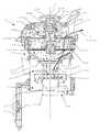
ここに,図1は,本発明の実施の形態に係る電気掃除機Xの外観図,図2及び図3は,本発明の実施の形態に係るサイクロン集塵装置Yの内部構造を説明するための断面図,図4は,本発明の実施の形態に係るサイクロン集塵装置Yに設けられた螺旋状回転圧縮部を説明するための図,図5は,本発明の実施の形態に係るサイクロン集塵装置の上蓋を開けた状態を示す分解斜視図,図6は,本発明の実施の形態に係るサイクロン集塵装置Yの内部構造を螺旋状回転圧縮部を中心として説明するための断面図,図7は,本発明の実施の形態に係るサイクロン集塵装置Yの内部構造を説明するための分解斜視図,図8は,本発明の実施の形態に係るサイクロン集塵装置Yの螺旋状回転圧縮部への回転力伝達経路を説明するための断面図,図9は,螺旋状回転圧縮部の回転によって,塵埃が圧縮・積層される状況を説明するサイクロン集塵装置Yの断面図,図10は,集塵容器から底蓋を分離した状態を示す斜視図,図11は,分離した底蓋を示す図,図12(a)は,底蓋のロック機構を示す正面図,(b)は,底蓋のロック機構とヒンジ機構を示す平断面図,図13は,ロック機構の開閉状態を示す集塵容器の側面図である。Hereinafter, embodiments of the present invention will be described with reference to the accompanying drawings so that the present invention can be understood. The following embodiment is an example embodying the present invention, and does not limit the technical scope of the present invention.
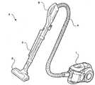
Here, FIG. 1 is an external view of the vacuum cleaner X according to the embodiment of the present invention, and FIGS. 2 and 3 are for explaining the internal structure of the cyclone dust collecting apparatus Y according to the embodiment of the present invention. FIG. 4 is a diagram for explaining a spiral rotary compression unit provided in the cyclone dust collecting apparatus Y according to the embodiment of the present invention, and FIG. 5 is a cyclone according to the embodiment of the present invention. FIG. 6 is an exploded perspective view showing a state in which the upper lid of the dust collector is opened, and FIG. 6 is a cross-sectional view for explaining the internal structure of the cyclone dust collector Y according to the embodiment of the present invention centering on the helical rotary compression unit. FIG. 7 is an exploded perspective view for explaining the internal structure of the cyclone dust collector Y according to the embodiment of the present invention, and FIG. 8 is a spiral shape of the cyclone dust collector Y according to the embodiment of the present invention. FIG. 9 is a cross-sectional view for explaining a rotational force transmission path to the rotary compression unit. FIG. 10 is a cross-sectional view of the cyclone dust collector Y for explaining the situation where dust is compressed and stacked by the rotation of the spiral rotary compression unit. FIG. 10 is a perspective view showing a state where the bottom cover is separated from the dust container. Fig. 12 (a) is a front view showing the bottom lid locking mechanism, Fig. 12 (b) is a plan view showing the bottom lid locking mechanism and the hinge mechanism, and Fig. 13 It is a side view of a dust collecting container which shows the open / close state of a lock mechanism.
まず,図1を用いて,本発明の実施の形態に係る電気掃除機Xの概略構成について説明する。
図1に示すように,前記電気掃除機Xは,掃除機本体部1,吸気口部2,接続管3,接続ホース4,操作ハンドル5などを備えて概略構成されている。前記掃除機本体部1には,不図示の電動送風機,サイクロン集塵装置Y,図外の制御装置などが内蔵されている。なお,前記サイクロン集塵装置Yについては後段で詳述する。
前記電動送風機は,吸気を行うための送風ファン及び該送風ファンを回転駆動する送風駆動モータを有している。前記制御装置は,CPUやRAM,ROMなどの制御機器を有してなり,前記電気掃除機Xを統括的に制御する。具体的には,前記制御装置では,前記CPUが前記ROMに記憶された制御プログラムに従って各種の処理を実行する。
なお,前記操作ハンドル5には,ユーザが前記電気掃除機Xの稼働の有無や運転モードの選択操作などを行うための操作スイッチ(不図示)が設けられている。また,その操作スイッチの近傍には,前記電気掃除機Xの現在の状態を表示するLEDなどの表示部(不図示)も設けられている。First, the schematic configuration of the electric vacuum cleaner X according to the embodiment of the present invention will be described with reference to FIG.
As shown in FIG. 1, the electric vacuum cleaner X is schematically configured to include a vacuum cleaner
The electric blower has a blower fan for performing intake air and a blower drive motor that rotationally drives the blower fan. The control device includes control devices such as a CPU, a RAM, and a ROM, and comprehensively controls the electric vacuum cleaner X. Specifically, in the control device, the CPU executes various processes according to a control program stored in the ROM.
The operation handle 5 is provided with an operation switch (not shown) for allowing the user to operate the vacuum cleaner X and to select an operation mode. A display unit (not shown) such as an LED for displaying the current state of the electric vacuum cleaner X is also provided in the vicinity of the operation switch.
前記掃除機本体部1は,該掃除機本体部1の前端に接続された前記接続ホース4と,該接続ホース4に接続された前記接続管3とを介して前記吸気口部2に接続されている。
従って,前記電気掃除機Xでは,前記掃除機本体部1に内蔵された前記電動送風機(不図示)が作動されることにより,前記吸気口部2からの吸気が行われる。そして,前記吸気口部2から吸気された空気は,前記接続管3及び前記接続ホース4を通じて前記サイクロン集塵装置Yに流入する。前記サイクロン集塵装置Yでは,吸い込まれた空気から塵埃が遠心分離される。なお,前記サイクロン集塵装置Yで塵埃が分離された後の空気は,前記掃除機本体部1の後端に設けられた不図示の排気口から排気される。The
Therefore, in the electric vacuum cleaner X, the electric blower (not shown) built in the vacuum cleaner
以下,図2〜6を参照しつつ,本発明に係るサイクロン集塵装置の一例であるサイクロン集塵装置Yについて詳説する。
図2及び図3に示すように,前記サイクロン集塵装置Yは,筐体10,内周面が略円筒状で,上記筐体10に対して着脱自在の集塵容器11(捕集容器の一例),内筒12,上部フィルタユニット13,塵埃受部14及び除塵駆動機構15などを備えて概略構成されている。
前記サイクロン集塵装置Yでは,前記集塵容器11,前記内筒12,前記上部フィルタユニット13,及び前記塵埃受部14が,垂直の中心軸Pを中心に同軸状に配置されている。また,前記サイクロン集塵装置Yは,前記掃除機本体部1に着脱可能に構成されている。
上記上蓋の一例である筐体10は,フィルタ122を備えた内筒12を備えている。
このサイクロン集塵装置Yでは,略円筒状の集塵容器11の中心部に設けられた前記内筒12から前記集塵容器11内の空気を排気することにより,前記集塵容器11の円周部に設けられた空気流入口111a(図7参照)から吸い込まれた空気を集塵容器11の内周面に沿って旋回させた後,フィルタ手段の一例である前記上部フィルタユニット13などを経て前記内筒12を経て排気し,前記空気に含まれる比較的大きい捕集対象物を前記集塵容器11の底部で捕集すると共に,比較的小さい捕集対象物を前記上部フィルタユニット13などにおいて捕集するものである。Hereinafter, the cyclone dust collector Y which is an example of the cyclone dust collector according to the present invention will be described in detail with reference to FIGS.
As shown in FIGS. 2 and 3, the cyclone dust collector Y has a
In the cyclone dust collecting apparatus Y, the
The
In the cyclone dust collecting apparatus Y, the air in the
前記集塵容器11は,吸い込まれた空気から分離された塵埃を収容するための内周面が円筒状で,且つ外形も円筒状の容器である。前記集塵容器11は,前記サイクロン集塵装置Yの筐体10に着脱可能に構成されている。
集塵容器11の底部には,図2に示すように底蓋310が開閉自在に取り付けられている。図2は底蓋310が閉じた状態を,図3は開いた状態を示す。ユーザは,前記掃除機本体部1から前記サイクロン集塵装置Yを取り出した後,上記底蓋310を図3に示すように開いて,該集塵容器11内の塵埃を廃棄する。上記底蓋310の開閉機構及び離脱手段などについては追って詳述される。
なお,前記サイクロン集塵装置Yの筐体10と前記集塵容器11との間には,環状のシール部材161が設けられている。このシール部材161により,前記筐体10及び前記集塵容器11の間の空気の漏れが防止される。
また,前記集塵容器11の上記底蓋310には,前記内筒12に設けられた後述の回転軸部123bに嵌合する嵌合部11aが設けられている。前記嵌合部11aの外周部には,前記内筒12の回転軸部123bとの隙間を埋めるための環状のシール部材11bが設けられている。このシール部材11bにより,前記回転軸部123b及び前記集塵容器11の間の空気の漏れが防止される。The
A
An annular seal member 161 is provided between the casing 10 of the cyclone dust collector Y and the
Further, the
さらに,前記集塵容器11には,前記接続ホース4(図1参照)が接続される接続部111が設けられている。前記吸気口部2から前記接続管3及び前記接続ホース4を通じて吸い込まれた空気は,前記接続部111から前記集塵容器11内に流入する。
ここで,前記接続部111の前記集塵容器11への空気流入口111aは,前記接続ホース4からの空気が前記集塵容器11内で旋回するように形成されている。具体的には,前記空気流入口111aは,該集塵容器11の接線方向に向くように形成されていることで,流入口111aから吸い込まれた空気は集塵容器11の内周に沿って旋回する。従って,旋回する空気に含まれた塵埃は旋回による遠心力で集塵容器11の内周面に押し付けられ,そのために旋回の速度を失って集塵容器11の底に落下し,旋回空気から分離(遠心分離)される。そして,前記集塵容器11で遠心分離された塵埃は,該集塵容器11の底部に収容される。
一方,塵埃が分離された後の空気は,前記集塵容器11から矢印112a(図2)で示す排気経路112に沿って前記掃除機本体部1に設けられた不図示の排気口から外部に排気される。ここで,前記集塵容器11から前記排気口(不図示)までの前記排気経路112上には,前記内筒12,前記塵埃受部14,及び前記上部フィルタユニット13が順に配置されており,空気流中の比較的細かい塵埃が内筒12および上部フィルタユニット13に設けられたフィルタによって取り除かれる。Further, the
Here, the
On the other hand, the air after the dust is separated is discharged from the exhaust port (not shown) provided in the
前記内筒12は,前記集塵容器11内に配置された円筒状の部材である。ここで,前記内筒12は,前記塵埃受部14によって回転可能に支持されている。具体的に,前記内筒12は,該内筒12の上端に設けられた環状の凹部12aが,前記塵埃受部14の下端に設けられた環状の支持部14cに支持されることにより,塵埃受部14と一体に回転可能な状態で吊り下げられている。なお,前記内筒12を回転可能に支持する構成は,これに限られるものではない。例えば,前記内筒12の上下の端部を軸支することが一例として考えられる。
詳細には,前記内筒12の上端には,後述の傾斜除塵部材134に設けられた係合部134cに係合する複数の連結部12bが設けられている。前記連結部12bは,前記内筒12の上端の開口縁部に上方に突出して設けられたリブである。
前記内筒12は,前記連結部12b及び前記係合部134cの係合によって,前記傾斜除塵部材134に一体回転可能に連結されている。これにより,前記内筒12は,前記傾斜除塵部材134に連動して回転することになる。なお,前記内筒12及び前記傾斜除塵部材134の連結構造はこれに限られない。例えば,前記内筒12及び前記傾斜除塵部材134各々に設けられた嵌合部を嵌合させることにより一体回転可能に連結する構成が考えられる。The
Specifically, the upper end of the
The
また,前記内筒12の上部には,前記集塵容器11で塵埃が分離された後の空気を,前記上部フィルタユニット13に向けて排気するための内筒排気口121が形成されている。そして,前記内筒排気口121には,該内筒排気口121全体を覆う円筒状を成す内筒フィルタ122が設けられている。前記内筒フィルタ122は,前記内筒排気口121を通過する空気を濾過する。
例えば,前記内筒フィルタ122は,メッシュ状のエアフィルタ等である。なお,前記内筒フィルタ122は,前記内筒排気口121の内側又は外側のいずれに設けられていてもよい。また,前記排気口121及び前記内筒フィルタ122に換えて,前記内筒12にメッシュ状の孔を形成する構成も考えられる。その場合は,そのメッシュ状の孔が前記内筒排気口121及び前記内筒フィルタ122として機能する。Further, an inner cylinder exhaust port 121 for exhausting the air after the dust is separated in the
For example, the inner cylinder filter 122 is a mesh air filter or the like. The inner cylinder filter 122 may be provided either inside or outside the inner cylinder exhaust port 121. Further, a configuration in which a mesh-like hole is formed in the
一方,前記内筒12の下部には,前記集塵容器11内の塵埃を圧縮するための垂直中心軸の周りに回転可能な螺旋状回転圧縮部123が設けられている。
ここで,図2及び図3に加えて螺旋状回転圧縮部123の斜視図である図4を参照しつつ,前記螺旋状回転圧縮部123について説明する。
図2〜4に示されているように,前記螺旋状回転圧縮部123には,螺旋状曲面を備えた螺旋部123a,回転軸部123b,円盤状遮蔽部材123cが設けられている。
前記回転軸部123bは,前記集塵容器11の底部に設けられた前記嵌合部11aに嵌合される中空円筒である。前述したように,前記回転軸部123b及び前記嵌合部11aの間には前記シール部材11b(図2,3参照)が介在する。On the other hand, at the lower part of the
Here, in addition to FIG. 2 and FIG. 3, the spiral
As shown in FIGS. 2 to 4, the spiral
The rotating shaft portion 123b is a hollow cylinder fitted to the fitting portion 11a provided at the bottom of the
円盤状遮蔽部材123cは,前記集塵容器11内において,後述する旋回流の遠心分離力により塵埃を分離する上側空間の部分(分離部104)と,塵埃を蓄積する下側空間の部分(集塵部105)との仕切りの役割を果たす。これにより,捕集した塵埃が巻き上がり,内筒フィルタ122を詰まらせる事を防ぐ。また,円盤状であるため,サイクロン気流中に含まれる塵埃が引っかかることが無く,塵埃を効率的に集塵容器11の底部へ誘導することができる。 The disk-shaped
また,前記回転軸部123bには,該回転軸部123bを中心にして,前記集塵部105の底面に向かって螺旋状に延び,その上下面が,前記垂直中心軸Pを中心とする螺旋状曲面を備えて湾曲した板状の螺旋部123a(圧縮部材の一例)が設けられている。前記螺旋部123aは,後述するように前記内筒12が回転されるとき,前記集塵容器11内に蓄積され,集塵容器11の内周面に接触して回転することに抵抗がある塵埃を,ネジの運び作用によって集塵容器11の底部向かって移動させる。この時,前記圧縮部材の前記螺旋状曲面が,該螺旋状曲面をネジと想定したときに,該圧縮部材の回転によりネジが後退するように形成されていることにより,この螺旋状曲面でゴミを圧縮することができる。
この時,前記螺旋部123aの前記螺旋状曲面は図6矢印Aの旋回気流と同様の傾斜方向をもって形成されていることが好ましい。このような螺旋部123aを図6矢印Aの旋回と反対方向に回転させることで前記集塵容器11内の塵埃は,該集塵容器11内面との摩擦によって,該集塵容器11底部へ移動することになる。
ただし,前記螺旋部123aの前記螺旋状曲面を,前記集塵容器11の内周面に沿って旋回する気流の傾き方向とは反対の方向に傾斜させることも可能である。この時,螺旋部123aの回転方向は,図6矢印Aの旋回気流の旋回方向と同一,即ち,螺旋部123aをネジと想定したとき,螺旋部123aの回転によりネジが後退する方向になる。
さらに,前記内筒12が回転されるとき,前記集塵容器11の底部まで移動した塵埃に対して前記螺旋部123aは,前記集塵容器11の底部との摩擦によって,上記底面との間で塵埃を回転により回転軸中心から外側に向かって押し出し圧縮することになる。このような構成によれば,塵埃が回転によって固く圧縮されるので,前記集塵容器11の塵埃の蓄積可能量を増加させることができる。従って,例えば前記集塵容器11の小型化を実現することが可能である。また,固く圧縮された塵埃は,容易に解けないので,取り出し時にも空気中に飛散する問題がなく,そのままの形でゴミとして廃棄することが出来る。Further, the rotating shaft portion 123b extends spirally around the rotating shaft portion 123b toward the bottom surface of the
At this time, it is preferable that the spiral curved surface of the
However, it is also possible to incline the spiral curved surface of the
Further, when the
ゴミを廃棄するには,前記したように底蓋310を開くことで開放される集塵容器11の底部開口330(図3参照)からゴミを取り出す。この時,ゴミを簡単に取り出せるように,底蓋310をワンタッチで開きうるようにすることが望ましい。また,底蓋310が開いた状態で外部のゴミ箱や家具などに接触すると,集塵容器11を含む集塵ボックス全体の重量がそれなりに大きいことともあいまって,底蓋310に大きい衝撃が加わり,底蓋310や集塵容器11が損傷する可能性がある。そこでこの実施形態に係る集塵容器11では,全開状態にある底蓋310にそれ以上開かせる方向の力が加わったときに,底蓋310が集塵容器11から外れるようにして,それ以上の力が底蓋310あるいは集塵容器11に加わることがないように構成されている。 In order to discard the dust, the dust is taken out from the bottom opening 330 (see FIG. 3) of the
具体的には以下のように構成されている。
図2は,集塵容器11の底部に底蓋310が取付けられ,底部の開口330が底蓋310で閉じられた状態を示している。また図3は,図2と同様の状態から底蓋310がヒンジ部334を中心に全開された状態を示している。ここでの全開は図2に示した全閉から約90°下向きに開いた状態である。
一方,図10は,上記図3に示した底蓋310が開の状態から,底蓋310に矢印332aで示す方向の外力を加えることで,底蓋310を矢印332aの方向に分離させた状態を示している。この時,底蓋310は,内部のバネやダンパーその他の部材がばらばらにならずに集塵容器11から分離されるように構成されている。
即ち,底蓋310は,その斜視図である図10に示すように,その外周上に軸受部336を備えている。上記ヒンジ部334は箱状の部材であり,底蓋310の外周に突出する上記軸受部336に回動自在に取付けられた支持軸338に取付けられている。
ヒンジ部334の左右端面には,ガイド溝348が形成されており,このガイド溝348の中程に取付けピン350がそれぞれ設けられている。
また,上記支持軸338の周りにはコイルバネ340が巻き付けられており,コイルバネ340は底蓋310を図3に示した全開の方向へ付勢する。
一方,前記集塵容器11の前記ヒンジ部334と対向する部分には,図10の(a)に示されるように,2本の取付け片344,344が固定されており,各取付け片344にはそれぞれ取付け孔346が形成されている。Specifically, it is configured as follows.
FIG. 2 shows a state in which a
On the other hand, FIG. 10 shows a state in which the
That is, the
A
On the other hand, as shown in FIG. 10A, two
従って,図10に示した底蓋310を集塵容器11から分離した状態で,矢印332bで示す方向(矢印332aとは反対方向)に底蓋310を移動させて,取付け片344をガイド溝348に差し込んでいくと,取付け片344の先端が取付けピン350に当接するが,取付け片344はプラスチックなどの弾性体であるので,上記当接によって撓み,取付け片344の間の距離が広がるので,取付けピン450の先端が取付け片344を乗り越え,やがて取付けピン450が取付け孔346に差し込まれ,ヒンジ部334が集塵容器11に一体的に結合される。 Accordingly, with the
このように集塵容器11に底蓋310が結合された状態で,何らかの衝突などで底蓋310に図1の矢印332aで示すような底蓋310をさらに開くような方向の力が加わると,その力が小さいうちは特に変化はないが,その力が大きくなると,前記した取付けピン450と取付け片344との間に力が集中し,取付け片344がその弾性によって撓み,取付け片344の取付け孔346から取付けピン450が抜けることとなり,底蓋310は矢印332aで示す方向に外れる。これによって底蓋310や集塵容器11あるいはヒンジ部334などの結合部が損傷すると言った不都合が回避される。従って,上記取付けピン450と取付け片344が,本発明における離脱機構の一例である。
なお,上記底蓋310の集塵容器11からの離脱時に,底蓋310が外れる他は,前記ピン338,コイルバネ340その他の何物も外れることがなく,従って,前記した取付け片344をガイド溝348に差し込むという簡単なワンタッチ操作で,再度集塵容器11に底蓋310を結合することが出来る。
さらに,底蓋310の前記軸受部336は,前記ヒンジ部334のコの字状の二股部354に装着されて前記支持軸338を中心に回動自在であり,且つ,図10(a)に示すように,底蓋310が全閉状態から90°程度開いた状態で,前記二股部354の水平部356に上記軸受部336が当接する。これによって,底蓋310がそれ以上回動しないように構成されている。従って,上記軸受部336が水平部356に当接して停止する機構が,本発明における角度維持手段の一例である。When the
When the
Further, the bearing
上記したような底蓋310は,図2のように閉じた状態で集塵容器11に固定(ロック)されねばならず,また,図3のように開くときには,ワンタッチで開きうるようにすることが望ましい。
そのために,図13に示すように,集塵容器11の下端の前記ヒンジ部334とは反対側の外周部には,ロック操作部342が設けられている。ロック操作部342は,集塵容器11の周面に固定された2本のガイドボルト358に案内されて,集塵容器11の外周面に沿って水平方向に滑動自在の操作部材360を備えている。
上記操作部材360は下向きに突出し,水平方向に屈曲し,斜面368を備えた2個のフック部材362を備えている。
さらに,前記底蓋311の上記フック部材362に対向する部分には,上記フック部材362と係合可能で斜面370を備えた2個のフック状の係合部材364が設けられている。
前記操作部材360は,集塵容器11との間に設けられたバネ366によって,前記フック部材362が係合部材364に係合する方向に常時付勢されている。
従って,図3のように開いた状態の底蓋310を閉じていくと,やがて,底蓋310側の係合部材362の斜面370が,操作部材360側のフック部材362の斜面368に当接し,底蓋310がさらに閉じる方向に押し込まれることで,上記斜面368に斜面370が押されることで,操作部材360が水平方向に移動して,係合部材364のフック部がフック部材362のフック部を超えた時点で,前記バネ366の力で操作部材360とこれに一体であるフック部材362が逆方向に移動して係合部材364とフック部材362が係合し,底蓋310が集塵容器11に固定される。
このように,操作者としては底蓋310を閉じる動作だけで底蓋310が集塵容器11にロックされるので,操作性の良いロック手段が提供されている。
また逆に,ロック状態にある底蓋310を開く時には,操作者が操作部材360を前記バネ366に逆らう方向に摺動させるだけで,前記フック部材362と係合部材364との係合が解除され,前記コイルバネ340の開方向の付勢力で底蓋310が開く。このように前記操作部材360を押すという単純な動作だけで底蓋310がワンタッチで開くので,重い集塵容器11を持たなければならない操作者としては,作業が単純化されて作業効率が著しく上がることになる。The
For this purpose, as shown in FIG. 13, a
The
Furthermore, two hook-shaped engaging members 364 that can be engaged with the hook member 362 and have an
The
Therefore, when the
Thus, since the
Conversely, when the
上記のように底蓋310をワンタッチで開く時に,底蓋310が急激に開くと,集塵容器11内に溜まったゴミが舞い上がって室内を汚染する可能性がある。そのため,この実施形態では,底蓋310の回転中心にダンパー372が設けられ,底蓋310の回転に対して抵抗を与えることで,底蓋310の急激な開き動作にブレーキを与えている。
上記ダンパー372としては,種々のものが適用可能であり,単に支持軸338にブレーキ部材を押しつける摩擦型のものであっても良く,あるいはオイルダンパー,エアダンパーなどであってもよい。If the
Various types of
前記のように螺旋状回転圧縮部123が回転することによって螺旋部123aにより圧縮された塵埃の一部は,長い髪の毛などを含んでいるので螺旋部123aに絡みつく。そのために,前記のように底蓋310を開放して,集塵容器11の底部に形成した開口330から塵埃を放出しようとしても簡単には外部に放出されない。また,塵埃を勢いよく放出すると塵埃に含まれる細かい塵などが空気中に散乱し,部屋を汚すことになる。そのため,何らかの方法で,簡単な操作で塵埃をゆっくり外部に放出する機構が必要である。そのために設けられた塵埃を簡単な操作でゆっくり外部に放出するため,以下のような機構が設けられている。
前記上部フィルタユニット13を内部に備えた上部筐体112の上面には取っ手314が設けられている。取っ手314は,外部から操作可能な操作部材の一例である。
上記取っ手134は,上記上部筐体312とは独立して垂直軸心の回りに回転自在である。上記取っ手134の内部には,斜面を構成する上側取っ手内蔵ギア316が一体に内蔵されており,上記上側取っ手内蔵ギア316と,同じく斜面を構成する下側取っ手内蔵ギア318とが同じ方向の斜面を接して対向している。上記のように上側取っ手内蔵ギア316と,下側取っ手内蔵ギア318とは,斜面同士であるので,上側の取っ手内蔵ギア316が回転すると下側取っ手内蔵ギア318が上記斜面に押されて下方に移動する。従って,取っ手314を回転させることで上側取っ手内蔵ギア316が下側取っ手内蔵ギア318と噛み合って取っ手314の回転が下側取っ手内蔵ギア318に伝えられる。
下側取っ手内蔵ギア318は,中間体320の上面に形成されており,中間体320の下面にはクラッチギア322が形成されているので,上記下側取っ手内蔵ギア318の下方への移動により中間体320と共にクラッチギア322も下方に移動することになる。
上記中間体320の下方には,図外の隙間を介してフィルタ除塵部材132に一体的に固定されたクラッチ受部326が設けられており,上記中間体320の下方への移動に伴ってクラッチギア322と上記クラッチ受部326とが噛み合い,取っ手314の回転がクラッチギア322とクラッチ受部326から構成されるクラッチ機構を介して,フィルタ除塵部材132に伝達され,フィルタ除塵部材132に連結された内筒12およびこれと一体に連結された螺旋状回転圧縮部材123が回転し,螺旋部123aが回転する。これによって,螺旋部123aのネジの運び作用により螺旋部123aに絡まった塵埃がゆっくりと螺旋部123aの先端方向に運ばれ,底蓋310が開くことによって開放された集塵容器11の底部開口から外部に放出される。
このように操作者によって取っ手314が回転されることで塵埃がゆっくりと外部に放出されるので,塵埃に含まれる細かい塵などが舞い上がったり飛散したりすることがなく,室内が塵などによって汚染されることがない。
尚,取っ手134から手を離すと,バネ収納部328に内蔵された図外のバネによって前記中間対320が押し上げられ,クラッチギア322とクラッチ受部326から構成されるクラッチ機構が開放される。これによって,取っ手134を操作しない限り上記クラッチ機構が開放状態にあるので,徐塵駆動モータ151によってフィルタ除塵部材132が回転されても,取っ手134が回転しないので,安全である。As described above, a part of the dust compressed by the
A
The handle 134 is rotatable around the vertical axis independently of the upper housing 312. The handle 134 has a built-in upper handle gear 316 that forms a slope, and the upper handle built-in gear 316 and the lower handle built-in gear 318 that also form a slope are inclined in the same direction. Facing each other. As described above, the upper handle built-in gear 316 and the lower handle built-in gear 318 are inclined surfaces. Therefore, when the upper handle built-in gear 316 rotates, the lower handle built-in gear 318 is pushed by the slope and moves downward. Moving. Therefore, by rotating the
The lower handle built-in gear 318 is formed on the upper surface of the
Below the
As the
When the hand is released from the handle 134, the
一方,前記内筒12の内筒フィルタ122で濾過された後の空気は,該内筒12内を通じて前記上部フィルタユニット13に導かれる。
ここで,図2及び図3に加えて図5を参照しつつ,前記上部フィルタユニット13について説明する。ここに,図5(a)は,前記上部フィルタユニット13を上方から見た斜視図,図5(b)は,前記上部フィルタユニット13を下方から見た斜視図である。
前記上部フィルタユニット13は,HEPAフィルタ(High Efficiency Particulate Air Filter)131,フィルタ除塵部材132及び傾斜除塵部材134などを有している。On the other hand, the air after being filtered by the inner cylinder filter 122 of the
Here, the
The
前記HEPAフィルタ131は,前記内筒12から排気されて前記排気経路112上を流れる空気をさらに濾過するエアフィルタの一種である。
前記HEPAフィルタ131は,前記垂直中心軸Pの周りに環状に配置固定された複数枚のフィルタの集合で構成されている。なお,複数枚のフィルタ各々は,例えば図5(b)に示すような骨組みに固定される。また,前記HEPAフィルタ131に含まれた複数枚のフィルタは,略水平方向に凹凸を繰り返すプリーツ状に配置されている。これにより,前記HEPAフィルタ131におけるフィルタ面積が十分に確保されている。なお,前記HEPAフィルタ131の下端と前記筐体10との間には,環状のシール部材162が設けられている。これにより,前記HEPAフィルタ131と前記筐体10との間の空気の漏れが防止される。
また,図2及び図3に示すように,前記HEPAフィルタ131の中央には,後述のフィルタ除塵部材132に設けられた連結部133が嵌挿される中空部131aが形成されている。また,前記中空部131aには,前記連結部133を回転可能に支持する支持部131bが設けられている。The
The
As shown in FIGS. 2 and 3, a hollow portion 131 a into which a connecting portion 133 provided in a filter dust removing member 132 described later is fitted is formed in the center of the
前述したように,前記サイクロン集塵装置Yでは,前記内筒フィルタ122及び前記HEPAフィルタ131の二段階で空気を濾過することにより塵埃の捕集力が高められている。
但し,前記HEPAフィルタ131に塵埃が堆積して目詰まりが生じると,空気の通過抵抗が大きくなる。そのため,前記電動送風機(不図示)の負荷が大きくなり吸塵力が低下するおそれがある。そこで,前記上部フィルタユニット13には,前記HEPAフィルタ131に付着した塵埃を除去する前記フィルタ除塵部材132が設けられている。As described above, in the cyclone dust collector Y, the dust collecting power is enhanced by filtering the air in two stages of the inner cylinder filter 122 and the
However, if dust accumulates on the
前記フィルタ除塵部材132は,前記HEPAフィルタ131の中央部に設けられた前記支持部131bによって回転可能に支持されている。具体的に,前記フィルタ除塵部材132には,前記支持部131bに回転可能に支持される連結部材133が設けられている。
また,前記連結部133には,該連結部133に設けられたネジ穴133aに前記傾斜除塵部材134がネジ133bで螺着される。これにより,前記フィルタ除塵部材132及び前記傾斜除塵部材134が一体回転可能に連結される。なお,前記傾斜除塵部材134及び前記HEPAフィルタ131の間には,隙間を埋める環状のシール部材163が設けられている。これにより,前記傾斜除塵部材134及び前記HEPAフィルタ131の間の空気の漏れが防止される。The filter dust removing member 132 is rotatably supported by the support portion 131 b provided at the center of the
In addition, the inclined dust removing member 134 is screwed into the connecting portion 133 with a screw 133b in a screw hole 133a provided in the connecting portion 133. Accordingly, the filter dust removing member 132 and the inclined dust removing member 134 are connected so as to be integrally rotatable. An annular seal member 163 that fills the gap is provided between the inclined dust removing member 134 and the
前記フィルタ除塵部材132は,図2及び図5(a)に示すように,前記HEPAフィルタ131の上端部に接触するように該HEPAフィルタ131に沿って所定間隔で配置された二つの接触部132aを有している。前記接触部132aは板バネ状の弾性部材である。なお,前記接触部132aは,板バネ状の弾性部材に限られるものではない。また,前記接触部132aは,一つであっても或いはさらに複数であってもよい。
そして,前記フィルタ除塵部材132には,その外周部にギア132bが形成されている。このギア132bは,図8に示すように,前記サイクロン集塵装置Yに設けられた除塵駆動機構15に設けられた除塵駆動モータ151の回転軸に設けられたギア15aに噛合される。As shown in FIGS. 2 and 5A, the filter dust removing member 132 includes two contact portions 132a disposed at predetermined intervals along the
The filter dust removing member 132 is formed with a
ここに,前記除塵駆動機構15は,図8に明らかな如く,前記掃除機本体部1側に設けられたの徐塵駆動モータ151(駆動モータの一例)を有している。前記除塵駆動機構15では,前記除塵駆動モータ151の回転力が前記ギア15aに伝達される。そして,前記除塵駆動機構15のギア15aの回転力は,前記ギア132bに伝達される。これにより,前記フィルタ除塵部材132が回転される。
そして,上記フィルタ除塵部材132の回転は,前記したように,傾斜除塵部材134に伝達され,傾斜除塵部材134と一体に回転する内筒12及び内筒12と一体の螺旋状回転圧縮部123が前記垂直中心軸Pの周りに回転する。
なお,本実施の形態では,前記除塵駆動モータによって前記フィルタ除塵部材132が回転される場合を例に挙げて説明するが,前記除塵駆動モータ151に換えて,前記フィルタ除塵部材132を手動で回転させることのできる機構を設けることも他の実施例として考えられる。
さらに,除塵駆動モータ以外の別のモータによって,螺旋状回転圧縮部123を回転させることも当然考えられる。上部フィルタユニット13の除塵と,螺旋状回転圧縮部123の回転とを別に行いたい場合には,このような別駆動の方を採用することも考えられる。Here, as shown in FIG. 8, the dust
The rotation of the filter dust removing member 132 is transmitted to the inclined dust removing member 134 as described above, and the
In this embodiment, the case where the filter dust removal member 132 is rotated by the dust removal drive motor will be described as an example. However, the filter dust removal member 132 is manually rotated instead of the dust
Further, it is naturally conceivable to rotate the helical
前記フィルタ除塵部材132が回転されると,該フィルタ除塵部材132に設けられた二つの前記接触部132a各々は,プリーツ状に形成された前記HEPAフィルタ131に断続的に衝突して振動を与える。従って,前記HEPAフィルタ131に付着した塵埃は,前記フィルタ除塵部材132から与えられる振動によって叩き落とされる。なお,前記除塵駆動モータ(不図示)が作動されるタイミングは,例えば前記電気掃除機Xにおける集塵動作の開始前や終了後であることが望ましい。これにより,前記電動送風機による吸気によって前記HEPAフィルタ131に下流側への気流がない状態で,前記HEPAフィルタ131の除塵を効果的に行うことができる。 When the filter dust removing member 132 is rotated, each of the two contact portions 132a provided in the filter dust removing member 132 intermittently collides with the
また,前述したように,前記塵埃受部14は,前記内筒12を回転可能に支持している。具体的に,前記塵埃受部14の開口14a縁部の下端には,前記内筒12の上端に設けられた環状の前記凹部12aに嵌合される環状の前記支持部14cが設けられている。これにより,前記内筒12は,前記塵埃受部14によって回転可能な状態で吊り下げられている。 As described above, the
次に,前記した螺旋状回転圧縮部123の構造についてさらに詳しく説明する。
前述したように,サイクロン集塵装置Yは,概略円筒形状に形成され,上部に配置された上部フィルタユニット13と,下部に配置された集塵容器11とを備えて構成されている。
集塵容器11内に収納された前記内筒12の下端には,分離部104と集塵部105の境界部である円盤状遮蔽部材123cが一体的に接合されている。上記円盤状遮蔽部材123cとその下部の前記螺旋部123aの外径は,ほぼ同じで,分離部104の内径より小さく,円盤状遮蔽部材123cの外周と集塵容器11の内壁との間には隙間(クリアランス)106(図2)が存在している。Next, the structure of the helical
As described above, the cyclone dust collector Y is formed in a substantially cylindrical shape, and includes the
A disc-shaped
隙間(クリアランス)106は,分離部104において分離した塵埃を集塵部105へ移動する場合に,ある程度の体積を持つ塵埃においてもスムーズに移動することができ,かつ一度集塵部105に移動・蓄積した塵埃を巻き上げ,内筒フィルタ122を詰まらさないようにするに適した値である。実験によれば13mm程度が望ましいことが分かった。 The clearance (clearance) 106 can smoothly move even when dust having a certain volume is transferred to the
また,円盤状遮蔽部材123cは,高さ方向に所定の厚みを持つ。円盤状遮蔽部材123cの高さ方向の厚みは,分離部104における遠心分離性能に影響し,本実施例では,実験により求めた13mm程度としている。 The disc-shaped
また,螺旋状回転圧縮部123の螺旋部123aは,前記したように上下の螺旋状曲面に挟まれて湾曲した板状に形成されており,円盤状遮蔽部材123cから下方に向かってほぼ垂直に伸びる回転軸部123bを中心にして,集塵容器11の底面に向かって始端(円盤状遮蔽部材123cとの接続部)から終端(下端)までが1周分以上,回転軸部123bの周囲に巻き付くように形成されている。上記巻き付き角度の望ましい数字としては,1.6周分である。このような巻き付きによって,螺旋部123aは,集塵容器11の内周面にそったサイクロン旋回気流の回転方向に沿って下方に向かって傾斜する螺旋状の旋回面が形成されている。 Further, as described above, the
また,螺旋状回転圧縮部123の螺旋部123aの終端(下端)と底蓋310の底面との間には,隙間(クリアランス)108(図2参照)が介在している。これにより,回転軸中心から外側に向け押し出し,圧縮することが出来る塵埃量を大幅に増加することが出来る。
また,上記隙間108の幅は,集塵部105の底部に押し付けられ,圧縮された塵埃が螺旋部分の終端と集塵部105底部の間に詰まることによる破損や,異物等の詰まりを起こすことを防ぐことができる値である。本実施例では,IEC規格に基づくDMT標準ゴミTYPE8を試験ゴミとして10g使用した実験により求めた上記隙間108の幅を6〜13mm程度としている。Further, a gap (clearance) 108 (see FIG. 2) is interposed between the terminal end (lower end) of the
Further, the width of the
以上のように構成された電気掃除機の動作について,以下に説明する。
図3,図6に示すように,分離部104の周方向に形成された接続部111の空気流入口111aから集塵容器11の分離部104に入った気流は,分離部104の円筒状の内周面に沿って高速で旋回する。旋回気流中の比較的大きい塵埃には遠心力が作用して気流から分離され,集塵容器11の内壁へ押し付けられる。図2に示すように,空気の排気口121が,下方にあるため,その後,気流は旋回しながら,集塵部105に入る。上記旋回する気流(主流)は,集塵部105の底面に到達した後は上昇に転じる。The operation of the vacuum cleaner configured as described above will be described below.
As shown in FIGS. 3 and 6, the airflow that enters the
また,図6に二点鎖線で示す矢印Aの気流により運ばれる塵埃は,螺旋部123aの終端部(下端部)と集塵容器11の底面との間の空間112aに引っかかり(トラップされ),蓄積され,螺旋部123aの螺旋形状の湾曲面に沿って下側から順に積層されていく。このため,さらに圧力損失の増加を防ぐことができる。 In addition, the dust carried by the air flow indicated by the two-dot chain line in FIG. 6 is trapped in the space 112a between the terminal end (lower end) of the
さらに,螺旋状回転圧縮部123のまわりの間隙107を旋回する気流の回転方向と螺旋状回転圧縮部123の螺旋部123aの傾き方向が一致しているため,蓄積・積層された塵埃は,気流によっても若干圧縮される。これにより,蓄積・積層された塵埃の容積が小さくなり,より効率的な塵埃捕集を達成できる。 Furthermore, since the rotational direction of the airflow swirling through the
次に,塵埃の空気流による蓄積と積層の作用について説明する。
前述したように,吸引された塵埃は,分離部104において分離され,隙間106(図2)を通り,集塵部105へ導かれる。集塵部105においては,塵埃は隙間107を通り,隙間108によりせき止められる(トラップされる)ことにより,蓄積される。この蓄積は,螺旋状回転圧縮部123が回転されるごとに既に蓄積された塵埃の上に積層されていく。そのため,この集塵装置では,螺旋部123aに沿って,偏ることなく積層が成長していくため,集塵部105内で偏って蓄積されていくことがなく,同容積の集塵部と比較して集塵可能容量が飛躍的に向上する。
また,螺旋部123aは,サイクロン旋回気流の回転方向に沿って下方に向かって傾斜する方向性をもつ螺旋形状とすることが出来る。この場合には,サイクロンの気流による圧縮効果も得られる。これにより,さらに集塵可能容量が向上する。Next, the accumulation of dust by the air flow and the action of stacking will be described.
As described above, the sucked dust is separated in the
Moreover, the
次に,回転圧縮の作用について具体的に説明する。
たとえば,送風駆動モータの駆動が停止されると,気流が旋回を止める。送風駆動モータの駆動停止が確認された後,除塵駆動機構15が駆動されると,上述したように内筒12,排気口121,円盤状遮蔽部材123c,螺旋状回転圧縮部123,回転軸部123bが一体となって,垂直中心軸Pを中心として,図8の矢印D方向(上面から見て,反時計方向)に回転する。このようにして,除塵駆動機構15による回転が,図8に示される第1の回転軸線152と第2の回転軸線153を介して回転軸部123bに伝達される。
こうして螺旋状回転圧縮部123が回転すると,ネジの原理により,回転軸方向(図9の矢印Eで示す垂直下向き方向)に推力が発生する。この推力により,集塵部105に蓄積されている図9の塵埃200は,回転軸方向に押し出され,集塵容器11の底面に押し付けられることにより回転軸方向に圧縮される。Next, the action of rotational compression will be specifically described.
For example, when the drive of the blower drive motor is stopped, the airflow stops turning. When the dust
When the helical
また,螺旋状回転圧縮部123が回転し圧縮動作を行うものであるため,螺旋状回転圧縮部123の回転によって塵埃に軸回転中心から外側向きの力が発生する。そのため,塵埃は円筒状の回転軸部123b部分にはあまり付着しない傾向があり,メンテナンス性が飛躍的に高まる。さらに,塵埃が螺旋状回転圧縮部123に付着した場合においても,螺旋状回転圧縮部123が回転することによって,塵埃を下方へ押し出し圧縮する際に塵埃により,剥がされていく。このように,螺旋状回転圧縮部123のメンテナンス性は非常に高い。 Further, since the helical
さらに,前記したように,圧縮後の塵埃はドーナツ型に固められ一体化しているため,ゴミ捨て時のゴミ飛散やこぼれ落ちなどを防ぐことができ,効率的なゴミ捨てが行える。 Furthermore, as described above, since the compressed dust is consolidated into a donut shape and integrated, it is possible to prevent dust scattering and spilling at the time of throwing away the garbage, and efficient garbage disposal.
螺旋状回転圧縮部123の回転を,モータなどの駆動手段によって行なうことにより,送風駆動モータの駆動中(吸引中)に螺旋状回転圧縮部123を自動的に回転させることができる。この動作によって,塵埃を捕集・集積すると同時に塵埃を圧縮することができる。これにより,さらに効率的に圧縮することができ,上記の効果がさらに高まる。また,一度に大量の塵埃を吸引した場合でも圧縮が可能なため,長時間連続して掃除を行うことができる。 By rotating the helical
さらにまた,送風駆動モータの駆動中(吸引中)に螺旋状回転圧縮部123を間欠的に回転させることにより,塵埃の捕集と同時に圧縮を行うことが出来るとともに,螺旋状回転圧縮部123を長い時間にわたって駆動し続けることがないため,消費電力の増加を防ぎ,駆動機構の寿命に伴う製品寿命を高めることができる。さらに,圧縮部駆動機構が駆動する際の騒音を低減することができ,より静かで使用しやすいサイクロン集塵装置が得られる。 Further, by intermittently rotating the helical
10…筐体(分離装置本体)
11…集塵容器(捕集容器)
12…内筒
13…上部フィルタユニット
14…塵埃受部
15…除塵駆動機構
104…分離部
105…集塵部
123…螺旋状回転圧縮部
123a…螺旋部(圧縮部)
123b…回転軸部
123c…円盤状遮蔽部材
123d…始端部
200,201…塵埃
310…底蓋
314…取っ手
316…上側取っ手内蔵ギア
318…下側取っ手内蔵ギア
319…隙間
320…中間体
322…クラッチギア
324…隙間
326…クラッチ受部
330…開口
332a,b…矢印
334…ヒンジ部
336…軸受部
338支持軸
340…コイルバネ
342…ロック操作部
344…取付け片
346…取付け孔
348…ガイド溝
350…取付けピン
352…ブラケット
354…二股部
356…水平部
358…ガイドボルト
360…操作部材
362…フック部材
364…係合部材
366…バネ
368…斜面
370…斜面
372…ダンパー10 ... Case (separator main body)
11 ... Dust collection container (collection container)
DESCRIPTION OF
123b ...
Claims (7)
Translated fromJapanese前記捕集容器内に,該捕集容器の垂直中心軸を中心とする螺旋状曲面を備え前記垂直中心軸の周りに回転可能な圧縮部材を備えてなると共に,前記捕集容器の底部に該捕集容器の底部に形成された開口を開閉自在の底蓋が設けられてなるサイクロン分離装置において,
全開状態にある前記底蓋にそれ以上に開く方向の力がかかった場合に,該底蓋が前記捕集容器から外れる離脱機構を備えてなることを特徴とするサイクロン分離装置。An inner peripheral surface is provided with a substantially cylindrical collection container, and air sucked from an air inlet provided in the circumferential direction on the circumferential portion of the collection container is disposed along the substantially cylindrical inner peripheral surface. After swirling, the relatively large collection object contained in the air is collected at the bottom of the collection container and is relatively small by exhausting from the center of the collection container through the filter means. A cyclone separation device for collecting an object to be collected in the filter means,
The collection container has a helically curved surface centered on the vertical central axis of the collection container, and a compression member that can rotate around the vertical central axis, and at the bottom of the collection container In the cyclone separation apparatus provided with a bottom lid that can freely open and close an opening formed in the bottom of the collection container,
A cyclone separation device comprising: a detaching mechanism that disengages the bottom lid from the collection container when a force in the direction of further opening is applied to the bottom lid in the fully open state.
Priority Applications (1)
| Application Number | Priority Date | Filing Date | Title |
|---|---|---|---|
| JP2008251159AJP2010081968A (en) | 2008-09-29 | 2008-09-29 | Cyclone separator |
Applications Claiming Priority (1)
| Application Number | Priority Date | Filing Date | Title |
|---|---|---|---|
| JP2008251159AJP2010081968A (en) | 2008-09-29 | 2008-09-29 | Cyclone separator |
Publications (1)
| Publication Number | Publication Date |
|---|---|
| JP2010081968Atrue JP2010081968A (en) | 2010-04-15 |
Family
ID=42246534
Family Applications (1)
| Application Number | Title | Priority Date | Filing Date |
|---|---|---|---|
| JP2008251159APendingJP2010081968A (en) | 2008-09-29 | 2008-09-29 | Cyclone separator |
Country Status (1)
| Country | Link |
|---|---|
| JP (1) | JP2010081968A (en) |
Cited By (46)
| Publication number | Priority date | Publication date | Assignee | Title |
|---|---|---|---|---|
| JP2013059516A (en)* | 2011-09-14 | 2013-04-04 | Sharp Corp | Vacuum cleaner |
| JP2015120057A (en)* | 2015-03-31 | 2015-07-02 | シャープ株式会社 | Electric vacuum cleaner |
| JP2016187713A (en)* | 2016-08-10 | 2016-11-04 | シャープ株式会社 | Vacuum cleaner |
| US9888817B2 (en) | 2014-12-17 | 2018-02-13 | Omachron Intellectual Property Inc. | Surface cleaning apparatus |
| US9931005B2 (en) | 2013-02-28 | 2018-04-03 | Omachron lntellectual Property Inc. | Surface cleaning apparatus |
| US10016106B1 (en) | 2016-12-27 | 2018-07-10 | Omachron Intellectual Property Inc. | Multistage cyclone and surface cleaning apparatus having same |
| US10105023B2 (en) | 2009-03-11 | 2018-10-23 | Omachron Intellectual Property Inc. | Hand vacuum cleaner |
| US10136778B2 (en) | 2014-12-17 | 2018-11-27 | Omachron Intellectual Property Inc. | Surface cleaning apparatus |
| US10214349B2 (en) | 2016-12-28 | 2019-02-26 | Omachron Intellectual Property Inc. | Dust and allergen control for surface cleaning apparatus |
| US10244909B2 (en) | 2016-12-28 | 2019-04-02 | Omachron Intellectual Property Inc. | Dust and allergen control for surface cleaning apparatus |
| US10244910B2 (en) | 2016-12-28 | 2019-04-02 | Omachron Intellectual Property Inc. | Dust and allergen control for surface cleaning apparatus |
| US10251519B2 (en) | 2014-12-17 | 2019-04-09 | Omachron Intellectual Property Inc. | Surface cleaning apparatus |
| US10258210B2 (en) | 2016-12-27 | 2019-04-16 | Omachron Intellectual Property Inc. | Multistage cyclone and surface cleaning apparatus having same |
| US10271704B2 (en) | 2016-12-27 | 2019-04-30 | Omachron Intellectual Property Inc. | Multistage cyclone and surface cleaning apparatus having same |
| US10299643B2 (en) | 2016-12-27 | 2019-05-28 | Omachron Intellectual Property Inc. | Multistage cyclone and surface cleaning apparatus having same |
| US10322873B2 (en) | 2016-12-28 | 2019-06-18 | Omachron Intellectual Property Inc. | Dust and allergen control for surface cleaning apparatus |
| US10405709B2 (en) | 2016-12-27 | 2019-09-10 | Omachron Intellectual Property Inc. | Multistage cyclone and surface cleaning apparatus having same |
| US10433686B2 (en) | 2007-08-29 | 2019-10-08 | Omachron Intellectual Property Inc. | Configuration of a surface cleaning apparatus |
| US10464746B2 (en) | 2016-12-28 | 2019-11-05 | Omachron Intellectual Property Inc. | Dust and allergen control for surface cleaning apparatus |
| US10506904B2 (en) | 2017-07-06 | 2019-12-17 | Omachron Intellectual Property Inc. | Handheld surface cleaning apparatus |
| KR20190003256U (en)* | 2018-06-20 | 2019-12-30 | 비쎌 인코포레이티드 | Vacuum cleaner and dust plume reduction apparatus |
| US10537216B2 (en) | 2017-07-06 | 2020-01-21 | Omachron Intellectual Property Inc. | Handheld surface cleaning apparatus |
| US10602894B2 (en) | 2011-03-04 | 2020-03-31 | Omachron Intellectual Property Inc. | Portable surface cleaning apparatus |
| US10631693B2 (en) | 2017-07-06 | 2020-04-28 | Omachron Intellectual Property Inc. | Handheld surface cleaning apparatus |
| JP2020072931A (en)* | 2016-10-28 | 2020-05-14 | アイロボット・コーポレーション | Mobile cleaning robot with container |
| US10702113B2 (en) | 2017-07-06 | 2020-07-07 | Omachron Intellectual Property Inc. | Handheld surface cleaning apparatus |
| US10722086B2 (en) | 2017-07-06 | 2020-07-28 | Omachron Intellectual Property Inc. | Handheld surface cleaning apparatus |
| US10750913B2 (en) | 2017-07-06 | 2020-08-25 | Omachron Intellectual Property Inc. | Handheld surface cleaning apparatus |
| US10765277B2 (en) | 2006-12-12 | 2020-09-08 | Omachron Intellectual Property Inc. | Configuration of a surface cleaning apparatus |
| US10827891B2 (en) | 2016-12-27 | 2020-11-10 | Omachron Intellectual Property Inc. | Multistage cyclone and surface cleaning apparatus having same |
| US10842330B2 (en) | 2017-07-06 | 2020-11-24 | Omachron Intellectual Property Inc. | Handheld surface cleaning apparatus |
| US11006799B2 (en) | 2018-08-13 | 2021-05-18 | Omachron Intellectual Property Inc. | Cyclonic air treatment member and surface cleaning apparatus including the same |
| US11013378B2 (en) | 2018-04-20 | 2021-05-25 | Omachon Intellectual Property Inc. | Surface cleaning apparatus |
| US11013384B2 (en) | 2018-08-13 | 2021-05-25 | Omachron Intellectual Property Inc. | Cyclonic air treatment member and surface cleaning apparatus including the same |
| US11192122B2 (en) | 2018-08-13 | 2021-12-07 | Omachron Intellectual Property Inc. | Cyclonic air treatment member and surface cleaning apparatus including the same |
| US11246462B2 (en) | 2019-11-18 | 2022-02-15 | Omachron Intellectual Property Inc. | Multi-inlet cyclone |
| US11285495B2 (en) | 2016-12-27 | 2022-03-29 | Omachron Intellectual Property Inc. | Multistage cyclone and surface cleaning apparatus having same |
| US11751740B2 (en) | 2019-11-18 | 2023-09-12 | Omachron Intellectual Property Inc. | Multi-inlet cyclone |
| US11896186B1 (en) | 2016-04-11 | 2024-02-13 | Omachron Intellectual Property Inc. | Surface cleaning apparatus |
| US11903547B1 (en) | 2014-12-17 | 2024-02-20 | Omachron Intellectual Property Inc. | Surface cleaning apparatus |
| US11918170B2 (en) | 2016-04-11 | 2024-03-05 | Omachron Intellectual Property Inc. | Surface cleaning apparatus |
| US11992848B2 (en) | 2019-01-23 | 2024-05-28 | Omachron Intellectual Property Inc. | Surface cleaning apparatus |
| US12082759B2 (en) | 2017-09-15 | 2024-09-10 | Omachron Intellectual Property Inc. | Surface cleaning apparatus |
| US12213640B2 (en) | 2009-03-13 | 2025-02-04 | Omachron Intellectual Property Inc. | Surface cleaning apparatus |
| US12324557B2 (en) | 2007-08-29 | 2025-06-10 | Omachron Intellectual Property Inc. | Portable surface cleaning apparatus |
| US12441537B2 (en) | 2019-09-26 | 2025-10-14 | Omachron Intellectual Property Inc. | Dust and allergen control for surface cleaning apparatus |
- 2008
- 2008-09-29JPJP2008251159Apatent/JP2010081968A/enactivePending
Cited By (90)
| Publication number | Priority date | Publication date | Assignee | Title |
|---|---|---|---|---|
| US10765277B2 (en) | 2006-12-12 | 2020-09-08 | Omachron Intellectual Property Inc. | Configuration of a surface cleaning apparatus |
| US11700984B2 (en) | 2006-12-12 | 2023-07-18 | Omachron Intellectual Property Inc. | Configuration of a surface cleaning apparatus |
| US10433686B2 (en) | 2007-08-29 | 2019-10-08 | Omachron Intellectual Property Inc. | Configuration of a surface cleaning apparatus |
| US10542856B2 (en) | 2007-08-29 | 2020-01-28 | Omachron Intellectual Property Inc. | Configuration of a surface cleaning apparatus |
| US10561286B2 (en) | 2007-08-29 | 2020-02-18 | Omachron Intellectual Property Inc. | Configuration of a surface cleaning apparatus |
| US12324557B2 (en) | 2007-08-29 | 2025-06-10 | Omachron Intellectual Property Inc. | Portable surface cleaning apparatus |
| US10105023B2 (en) | 2009-03-11 | 2018-10-23 | Omachron Intellectual Property Inc. | Hand vacuum cleaner |
| US10238250B2 (en) | 2009-03-11 | 2019-03-26 | Omachron Intellectual Property Inc. | Hand vacuum cleaner |
| US12324556B2 (en) | 2009-03-11 | 2025-06-10 | Omachron Intellectual Property Inc. | Hand vacuum cleaner |
| US11969133B2 (en) | 2009-03-11 | 2024-04-30 | Omachron Intellectual Property Inc. | Hand vacuum cleaner |
| US12213640B2 (en) | 2009-03-13 | 2025-02-04 | Omachron Intellectual Property Inc. | Surface cleaning apparatus |
| US10602894B2 (en) | 2011-03-04 | 2020-03-31 | Omachron Intellectual Property Inc. | Portable surface cleaning apparatus |
| US11612283B2 (en) | 2011-03-04 | 2023-03-28 | Omachron Intellectual Property Inc. | Surface cleaning apparatus |
| JP2013059516A (en)* | 2011-09-14 | 2013-04-04 | Sharp Corp | Vacuum cleaner |
| US9931005B2 (en) | 2013-02-28 | 2018-04-03 | Omachron lntellectual Property Inc. | Surface cleaning apparatus |
| US10624511B2 (en) | 2013-02-28 | 2020-04-21 | Omachron Intellectual Property Inc. | Surface cleaning apparatus |
| US10638897B2 (en) | 2013-02-28 | 2020-05-05 | Omachron Intellectual Property Inc. | Surface cleaning apparatus |
| US11889968B2 (en) | 2013-02-28 | 2024-02-06 | Omachron Intellectual Property Inc. | Surface cleaning apparatus |
| US10362911B2 (en) | 2014-12-17 | 2019-07-30 | Omachron Intellectual Property Inc | Surface cleaning apparatus |
| US10219661B2 (en) | 2014-12-17 | 2019-03-05 | Omachron Intellectual Property Inc. | Surface cleaning apparatus |
| US11992167B2 (en) | 2014-12-17 | 2024-05-28 | Omachron Intellectual Property Inc. | Surface cleaning apparatus |
| US11918168B2 (en) | 2014-12-17 | 2024-03-05 | Omachron Intellectual Property Inc. | Surface cleaning apparatus |
| US11389038B2 (en) | 2014-12-17 | 2022-07-19 | Omachron Intellectual Property Inc. | Surface cleaning apparatus |
| US10251519B2 (en) | 2014-12-17 | 2019-04-09 | Omachron Intellectual Property Inc. | Surface cleaning apparatus |
| US12121198B2 (en) | 2014-12-17 | 2024-10-22 | Omachron Intellectual Property Inc. | Surface cleaning apparatus |
| US11986145B2 (en) | 2014-12-17 | 2024-05-21 | Omachron Intellectual Property Inc. | Surface cleaning apparatus |
| US10478030B2 (en) | 2014-12-17 | 2019-11-19 | Omachron Intellectul Property Inc. | Surface cleaning apparatus |
| US9888817B2 (en) | 2014-12-17 | 2018-02-13 | Omachron Intellectual Property Inc. | Surface cleaning apparatus |
| US11910983B2 (en) | 2014-12-17 | 2024-02-27 | Omachron Intellectual Property Inc. | Surface cleaning apparatus |
| US11903546B2 (en) | 2014-12-17 | 2024-02-20 | Omachron Intellectual Property Inc. | Surface cleaning apparatus |
| US10219660B2 (en) | 2014-12-17 | 2019-03-05 | Omachron Intellectual Property Inc. | Surface cleaning apparatus |
| US10117550B1 (en) | 2014-12-17 | 2018-11-06 | Omachron Intellectual Property Inc. | Surface cleaning apparatus |
| US10219662B2 (en) | 2014-12-17 | 2019-03-05 | Omachron Intellectual Property Inc. | Surface cleaning apparatus |
| US10624510B2 (en) | 2014-12-17 | 2020-04-21 | Omachron Intellectual Property Inc. | Surface cleaning apparatus |
| US10149585B2 (en) | 2014-12-17 | 2018-12-11 | Omachron Intellectual Property Inc. | Surface cleaning apparatus |
| US11903547B1 (en) | 2014-12-17 | 2024-02-20 | Omachron Intellectual Property Inc. | Surface cleaning apparatus |
| US10136778B2 (en) | 2014-12-17 | 2018-11-27 | Omachron Intellectual Property Inc. | Surface cleaning apparatus |
| JP2015120057A (en)* | 2015-03-31 | 2015-07-02 | シャープ株式会社 | Electric vacuum cleaner |
| US11918170B2 (en) | 2016-04-11 | 2024-03-05 | Omachron Intellectual Property Inc. | Surface cleaning apparatus |
| US11896186B1 (en) | 2016-04-11 | 2024-02-13 | Omachron Intellectual Property Inc. | Surface cleaning apparatus |
| JP2016187713A (en)* | 2016-08-10 | 2016-11-04 | シャープ株式会社 | Vacuum cleaner |
| JP2020072931A (en)* | 2016-10-28 | 2020-05-14 | アイロボット・コーポレーション | Mobile cleaning robot with container |
| US11918172B2 (en) | 2016-10-28 | 2024-03-05 | Irobot Corporation | Mobile cleaning robot with a bin |
| JP6999215B2 (en) | 2016-10-28 | 2022-01-18 | アイロボット・コーポレーション | Mobile cleaning robot with a container |
| US11357371B2 (en) | 2016-10-28 | 2022-06-14 | Irobot Corporation | Mobile cleaning robot with a bin |
| US10405709B2 (en) | 2016-12-27 | 2019-09-10 | Omachron Intellectual Property Inc. | Multistage cyclone and surface cleaning apparatus having same |
| US11673148B2 (en) | 2016-12-27 | 2023-06-13 | Omachron Intellectual Property Inc. | Surface cleaning apparatus |
| US11938491B2 (en) | 2016-12-27 | 2024-03-26 | Omachron Intellectual Property Inc. | Surface cleaning apparatus |
| US10016106B1 (en) | 2016-12-27 | 2018-07-10 | Omachron Intellectual Property Inc. | Multistage cyclone and surface cleaning apparatus having same |
| US10299643B2 (en) | 2016-12-27 | 2019-05-28 | Omachron Intellectual Property Inc. | Multistage cyclone and surface cleaning apparatus having same |
| US10271704B2 (en) | 2016-12-27 | 2019-04-30 | Omachron Intellectual Property Inc. | Multistage cyclone and surface cleaning apparatus having same |
| US11285495B2 (en) | 2016-12-27 | 2022-03-29 | Omachron Intellectual Property Inc. | Multistage cyclone and surface cleaning apparatus having same |
| US11331680B2 (en) | 2016-12-27 | 2022-05-17 | Omachron Intellectual Property Inc. | Surface cleaning apparatus |
| US12251716B2 (en) | 2016-12-27 | 2025-03-18 | Omachron Intellectual Property Inc. | Surface cleaning apparatus |
| US10258210B2 (en) | 2016-12-27 | 2019-04-16 | Omachron Intellectual Property Inc. | Multistage cyclone and surface cleaning apparatus having same |
| US10827891B2 (en) | 2016-12-27 | 2020-11-10 | Omachron Intellectual Property Inc. | Multistage cyclone and surface cleaning apparatus having same |
| US12297039B2 (en) | 2016-12-28 | 2025-05-13 | Omachron Intellectual Property Inc. | Dust and allergen control for surface cleaning apparatus |
| US10244909B2 (en) | 2016-12-28 | 2019-04-02 | Omachron Intellectual Property Inc. | Dust and allergen control for surface cleaning apparatus |
| US12234087B2 (en) | 2016-12-28 | 2025-02-25 | Omachron Intellectual Property Inc. | Dust and allergen control for surface cleaning apparatus |
| US10244910B2 (en) | 2016-12-28 | 2019-04-02 | Omachron Intellectual Property Inc. | Dust and allergen control for surface cleaning apparatus |
| US12234088B2 (en) | 2016-12-28 | 2025-02-25 | Omachron Intellectual Property Inc. | Dust and allergen control for surface cleaning apparatus |
| US10464746B2 (en) | 2016-12-28 | 2019-11-05 | Omachron Intellectual Property Inc. | Dust and allergen control for surface cleaning apparatus |
| US10214349B2 (en) | 2016-12-28 | 2019-02-26 | Omachron Intellectual Property Inc. | Dust and allergen control for surface cleaning apparatus |
| US12397987B2 (en) | 2016-12-28 | 2025-08-26 | Omachron Intellectual Property Inc. | Dust and allergen control for surface cleaning apparatus |
| US10322873B2 (en) | 2016-12-28 | 2019-06-18 | Omachron Intellectual Property Inc. | Dust and allergen control for surface cleaning apparatus |
| US10765278B2 (en) | 2017-07-06 | 2020-09-08 | Omachron Intellectual Property Inc. | Handheld surface cleaning apparatus |
| US10842330B2 (en) | 2017-07-06 | 2020-11-24 | Omachron Intellectual Property Inc. | Handheld surface cleaning apparatus |
| US11910984B2 (en) | 2017-07-06 | 2024-02-27 | Omachron Intellectual Property Inc. | Handheld surface cleaning apparatus |
| US10506904B2 (en) | 2017-07-06 | 2019-12-17 | Omachron Intellectual Property Inc. | Handheld surface cleaning apparatus |
| US10537216B2 (en) | 2017-07-06 | 2020-01-21 | Omachron Intellectual Property Inc. | Handheld surface cleaning apparatus |
| US10631693B2 (en) | 2017-07-06 | 2020-04-28 | Omachron Intellectual Property Inc. | Handheld surface cleaning apparatus |
| US11445875B2 (en) | 2017-07-06 | 2022-09-20 | Omachron Intellectual Property Inc. | Handheld surface cleaning apparatus |
| US10702113B2 (en) | 2017-07-06 | 2020-07-07 | Omachron Intellectual Property Inc. | Handheld surface cleaning apparatus |
| US10722086B2 (en) | 2017-07-06 | 2020-07-28 | Omachron Intellectual Property Inc. | Handheld surface cleaning apparatus |
| US12161280B2 (en) | 2017-07-06 | 2024-12-10 | Omachron Intellectual Property Inc. | Handheld surface cleaning apparatus |
| US10750913B2 (en) | 2017-07-06 | 2020-08-25 | Omachron Intellectual Property Inc. | Handheld surface cleaning apparatus |
| US11737621B2 (en) | 2017-07-06 | 2023-08-29 | Omachron Intellectual Property Inc. | Handheld surface cleaning apparatus |
| US12082759B2 (en) | 2017-09-15 | 2024-09-10 | Omachron Intellectual Property Inc. | Surface cleaning apparatus |
| US11375861B2 (en) | 2018-04-20 | 2022-07-05 | Omachron Intellectual Property Inc. | Surface cleaning apparatus |
| US11013378B2 (en) | 2018-04-20 | 2021-05-25 | Omachon Intellectual Property Inc. | Surface cleaning apparatus |
| US11930987B2 (en) | 2018-04-20 | 2024-03-19 | Omachron Intellectual Property Inc. | Surface cleaning apparatus |
| KR200498275Y1 (en) | 2018-06-20 | 2024-08-22 | 비쎌 인코포레이티드 | Vacuum cleaner and dust plume reduction apparatus |
| KR20190003256U (en)* | 2018-06-20 | 2019-12-30 | 비쎌 인코포레이티드 | Vacuum cleaner and dust plume reduction apparatus |
| US11006799B2 (en) | 2018-08-13 | 2021-05-18 | Omachron Intellectual Property Inc. | Cyclonic air treatment member and surface cleaning apparatus including the same |
| US11192122B2 (en) | 2018-08-13 | 2021-12-07 | Omachron Intellectual Property Inc. | Cyclonic air treatment member and surface cleaning apparatus including the same |
| US11013384B2 (en) | 2018-08-13 | 2021-05-25 | Omachron Intellectual Property Inc. | Cyclonic air treatment member and surface cleaning apparatus including the same |
| US11992848B2 (en) | 2019-01-23 | 2024-05-28 | Omachron Intellectual Property Inc. | Surface cleaning apparatus |
| US12441537B2 (en) | 2019-09-26 | 2025-10-14 | Omachron Intellectual Property Inc. | Dust and allergen control for surface cleaning apparatus |
| US11751740B2 (en) | 2019-11-18 | 2023-09-12 | Omachron Intellectual Property Inc. | Multi-inlet cyclone |
| US11246462B2 (en) | 2019-11-18 | 2022-02-15 | Omachron Intellectual Property Inc. | Multi-inlet cyclone |
Similar Documents
| Publication | Publication Date | Title |
|---|---|---|
| JP2010081968A (en) | Cyclone separator | |
| JP4750164B2 (en) | Cyclone separator | |
| JP4798637B2 (en) | Dust collector and vacuum cleaner | |
| JP5237770B2 (en) | Cyclone separator | |
| JP2010035771A (en) | Cyclone separator | |
| JP6867991B2 (en) | Vacuum cleaner | |
| WO2009116611A1 (en) | Cyclone separation apparatus | |
| JP4589989B2 (en) | Cyclone separator | |
| JP2009285415A (en) | Vacuum cleaner | |
| JP2010004909A (en) | Cyclone separator | |
| JP4378420B2 (en) | Cyclone separator | |
| JP5031807B2 (en) | Cyclone separator | |
| JP5177814B2 (en) | Dust collector and vacuum cleaner | |
| JP4856271B2 (en) | Cyclone separator | |
| JP4871416B2 (en) | Cyclone separator | |
| CN102578960B (en) | Electric dust collector | |
| JP5070127B2 (en) | Cyclone separator | |
| JP4478191B2 (en) | Cyclone separator | |
| JP5101457B2 (en) | Cyclone separator | |
| JP2018008154A (en) | Electric vacuum cleaner | |
| JP7365484B2 (en) | vacuum cleaner | |
| JP5066282B2 (en) | Cyclone separator | |
| JP2015006623A (en) | Cyclone separator, vacuum cleaner | |
| JP5122406B2 (en) | Cyclone separator | |
| JP5184428B2 (en) | Cyclone separator |
Legal Events
| Date | Code | Title | Description |
|---|---|---|---|
| RD03 | Notification of appointment of power of attorney | Effective date:20110303 Free format text:JAPANESE INTERMEDIATE CODE: A7423 |