JP2010080138A - High-pressure discharge lamp lighting device, and lighting fixture - Google Patents
High-pressure discharge lamp lighting device, and lighting fixtureDownload PDFInfo
- Publication number
- JP2010080138A JP2010080138AJP2008244950AJP2008244950AJP2010080138AJP 2010080138 AJP2010080138 AJP 2010080138AJP 2008244950 AJP2008244950 AJP 2008244950AJP 2008244950 AJP2008244950 AJP 2008244950AJP 2010080138 AJP2010080138 AJP 2010080138A
- Authority
- JP
- Japan
- Prior art keywords
- wave
- discharge lamp
- voltage
- pressure discharge
- circuit
- Prior art date
- Legal status (The legal status is an assumption and is not a legal conclusion. Google has not performed a legal analysis and makes no representation as to the accuracy of the status listed.)
- Pending
Links
Images


Classifications
- Y02B20/14—
- Y02B20/204—
Landscapes
- Circuit Arrangements For Discharge Lamps (AREA)
- Rectifiers (AREA)
- Inverter Devices (AREA)
Abstract
Translated fromJapaneseDescription
Translated fromJapanese本発明は高圧放電灯点灯装置及びこれを用いた照明器具に関するものである。 The present invention relates to a high-pressure discharge lamp lighting device and a lighting fixture using the same.
高圧放電灯は、高輝度・高光出力の照明として広く使用されているが、放電ランプの一種であり、安定な点灯のためには、安定器と呼ばれる点灯装置が必要である。点灯装置には、主にインダクタンスで構成される銅鉄式と、電子回路のスイッチング制御を利用した電子式とがあるが、近年では、省電力の観点から、電子式の普及が増加している。 High-pressure discharge lamps are widely used as illumination with high luminance and high light output, but are a kind of discharge lamps, and a lighting device called a ballast is necessary for stable lighting. There are two types of lighting devices, a copper-iron type mainly composed of inductance, and an electronic type that uses switching control of an electronic circuit. In recent years, the spread of electronic types has increased from the viewpoint of power saving. .
(従来例1)
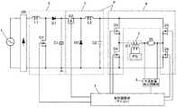
電子式の高圧放電灯点灯装置の一例を、図29に示す。この高圧放電灯点灯装置は、商用交流電源1に接続され、その交流電圧を整流する整流器DBと、整流器DBで整流された電圧を入力として直流電圧Vdcを出力する直流電源回路2と、直流電圧Vdcを矩形波交流電圧に変換して、高圧放電灯DLに印加するインバータ回路4と、高圧放電灯DLの始動・再始動のための高電圧を発生する始動回路5と、高圧放電灯DLの状態を検出する検出回路部6と、インバータ回路4のスイッチング素子Q3〜Q6を制御する制御回路7と、直流電源回路2のスイッチング素子Q1を制御する制御回路9とから構成されている。(Conventional example 1)
An example of an electronic high pressure discharge lamp lighting device is shown in FIG. This high-pressure discharge lamp lighting device is connected to a commercial
検出回路部6は、高圧放電灯DLの状態として、高圧放電灯DLの両端への印加電圧を検出する検出回路6aと、検出回路6aの出力を受けて、半波放電状態の有無を検出する半波放電検出部6bを備えている。 The
制御回路7は、検出回路部6の検出結果により、高圧放電灯DLの点灯・非点灯を判別する点灯判別手段7aと、点灯判別手段7aの点灯判別信号を受けて、インバータ回路4の動作を、高圧放電灯DLの始動用の高電圧を発生するための第1の動作状態と、高圧放電灯DLを安定に点灯するための第2の動作状態に切替える切替回路7bと、検出回路部6の検出結果を受けて、スイッチング素子Q5およびQ6のチョッピング周波数およびON期間を決定する演算回路7cを備えており、演算回路7cの出力は、切替回路7bを通して、第2の動作状態の時に、各スイッチング素子Q3〜Q6を制御する。 The
制御回路9は、直流電源回路2の出力電圧Vdcを検出するVdc検出回路9aと、Vdc検出回路9aの検出結果に応じて、スイッチング素子Q1を制御するQ1制御回路9bとから構成されている。 The
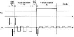
図29の高圧放電灯点灯装置の各部の波形を図30に示す。商用交流電源Vsの投入から、高圧放電灯DLが安定点灯するまでの動作を示しており、上から商用交流電源1の交流電圧Vs、直流電源回路2としての昇圧チョッパ回路の出力電圧Vdc、高圧放電灯(HIDランプ)DLの両端電圧Vo、ランプ電流Io、点灯判別手段7aの出力、スイッチング素子Q3〜Q6の動作状態を示している。 The waveform of each part of the high pressure discharge lamp lighting device of FIG. 29 is shown in FIG. The operation from when the commercial AC power supply Vs is turned on until the high-pressure discharge lamp DL is steadily lit is shown. From the top, the AC voltage Vs of the commercial
商用交流電源Vsが投入されると、直流電源回路2は、制御回路9がスイッチング素子Q1を数10kHz程度でON/OFFさせ、直流電圧Vdcに応じてパルス幅を適正に制御することにより、高圧放電灯DLが点灯していない非点灯時、ならびに高圧放電灯DLが点灯している点灯時ともに、直流電圧Vdcを所定値に一定化している。また、直流電源回路2は、商用交流電源1からの入力力率を高め、入力電流歪を抑制する機能をも有している。 When the commercial AC power supply Vs is turned on, the DC
直流電圧Vdcが所定値に達すると、インバータ回路4が動作を開始する。この時点で、高圧放電灯DLは点灯していない非点灯状態であり、高圧放電灯DLは開放状態と同一で、等価インピーダンスは無限大に近い、高インピーダンス状態である。このとき、インバータ回路4は、高圧放電灯DLを始動するための第1の動作状態で動作を開始し、スイッチング素子Q3とQ6がONの状態と、スイッチング素子Q4とQ5がONの状態とを、所定の周波数f0(数100kHz程度)で交互に繰り返す。この周波数f0は、パルストランスL3の1次巻線N1とコンデンサC3からなる直列共振回路の共振周波数frに近い周波数であり、正弦波状の高電圧が1次巻線N1に発生する。1次巻線N1に発生した正弦波状の高電圧は、パルストランスL3の1次巻線N1と2次巻線N2の巻数比によって昇圧され、コンデンサC2を介して高圧放電灯DLに印加される。これによって、高圧放電灯DLは絶縁破壊し、始動する。 When the DC voltage Vdc reaches a predetermined value, the
高圧放電灯DLが始動すると、高圧放電灯DLは短絡に近い低インピーダンス状態になり、高圧放電灯DLの両端電圧Voは略0Vに低下する。高圧放電灯DLの両端電圧が点灯判別電圧しきい値を下回ると、点灯判別手段7aは、高圧放電灯DLが点灯したと判別し、点灯判別手段7aの出力信号はHレベルからLレベルに切り替わり、制御回路7の切替回路7bに入力される。切替回路7bは、この信号を受けて、インバータ回路4の動作を、高圧放電灯DLを安定に点灯するための、第2の動作状態に切り替える。 When the high-pressure discharge lamp DL is started, the high-pressure discharge lamp DL becomes in a low impedance state close to a short circuit, and the voltage Vo across the high-pressure discharge lamp DL decreases to approximately 0V. When the both-ends voltage of the high-pressure discharge lamp DL falls below the lighting determination voltage threshold value, the lighting determination means 7a determines that the high-pressure discharge lamp DL is lit, and the output signal of the lighting determination means 7a switches from H level to L level. , And input to the switching circuit 7b of the
インバータ回路4は、第2の動作状態では、スイッチング素子Q3とQ4が所定の周波数fa(数100Hz程度)で交互にON/OFFし、その際、スイッチング素子Q5およびQ6は、スイッチング素子Q3がONの期間では、スイッチング素子Q6が所定の周波数fb(数10kHz程度)でON/OFFし、スイッチング素子Q4がONの期間では、スイッチング素子Q5が所定の周波数fb(数10kHz程度)でON/OFFする動作を繰り返す。この極性反転型降圧チョッパ動作により、高圧放電灯DLには、周波数faの矩形波交流電圧が印加される。このとき、コンデンサC2とインダクタL2は降圧チョッパ回路のフィルタ回路として機能し、スイッチング素子Q5,Q6に内蔵された逆並列ダイオードは降圧チョッパ回路の回生電流通電用ダイオードとして機能する。 In the
高圧放電灯DLは、始動直後はランプ両端電圧が低く、ランプ内部が高温・高圧になるにつれてランプ両端電圧が上昇し、定格値に至り、安定点灯状態になる。 The high-pressure discharge lamp DL has a low voltage across the lamp immediately after start-up, the voltage across the lamp rises as the temperature inside the lamp becomes high and high, reaches a rated value, and is in a stable lighting state.
制御回路7では、検出回路6aにより高圧放電灯DLの状態を検出し、高圧放電灯DLの両端電圧に応じて、演算回路7cにより、スイッチング素子Q5、Q6のチョッピング周波数やON期間を適正に制御することにより、適正な電力が高圧放電灯DLに供給されるように制御し、高圧放電灯DLを安定点灯させる。 In the
従来例では、始動過程では誤検出を防止するために半波放電の検出機能を停止させており、高圧放電灯DLが安定点灯状態に移行した後に検出動作を開始し、半波放電を検出すると、高圧放電灯DLの寿命末期が到来したと判定して、点灯装置の出力を停止または低減する保護動作に移行させる。 In the conventional example, the detection function of half-wave discharge is stopped in the starting process to prevent false detection, and the detection operation is started after the high-pressure discharge lamp DL shifts to a stable lighting state, and half-wave discharge is detected. Then, it is determined that the end of the life of the high-pressure discharge lamp DL has come, and the protection operation is performed to stop or reduce the output of the lighting device.
(従来例2)
別の高圧放電灯点灯装置の一例を図31に示す。この点灯装置は、商用交流電源1に接続され、その交流電圧を整流する整流器DBと、整流器DBで整流された電圧を入力として直流電圧Vdcを出力する直流電源回路2と、直流電圧Vdcを電源として、高圧放電灯DLに適正な電力を供給するよう制御される降圧チョッパ回路3と、降圧チョッパ回路3の直流出力を矩形波交流電圧に変換して、高圧放電灯DLに印加するインバータ回路4と、高圧放電灯DLの始動のために必要な高電圧を発生・印加する始動パルス発生回路と、これらを適正に動作するよう制御する制御回路とから構成されている。(Conventional example 2)
An example of another high pressure discharge lamp lighting device is shown in FIG. This lighting device is connected to a commercial
始動パルス発生回路の構成の詳細を説明する。始動パルス発生回路は、インバータ回路4の出力と高圧放電灯DLとの間に2次巻線N2を接続されたパルストランスPTと、両端の電圧が所定値を越えた際にオンする電圧応答型のスイッチング素子Q7と、パルストランスPTの1次巻線N1とスイッチング素子Q7と直列に接続されるコンデンサC7と、スイッチング素子Q7と並列に接続され、スイッチング素子Q7がオフ時に、コンデンサC7を充電する電流を制御する抵抗R7からなる。 Details of the configuration of the start pulse generation circuit will be described. The starting pulse generating circuit includes a pulse transformer PT in which a secondary winding N2 is connected between the output of the
制御回路の構成について説明する。半波放電検出回路部6や点灯判別手段7a、力率改善制御回路部9については、図29と同様の構成で良い。降圧チョッパ出力検出部7dは、降圧チョッパ回路3の出力電圧を検出し、降圧チョッパ制御回路部8は、高圧放電灯DLに適正な電力を供給するために、降圧チョッパ回路3の出力電圧に応じた所定の電流となるようにスイッチング素子Q2を制御する。極性反転制御回路7eは、インバータ回路4のスイッチング素子Q3〜Q6の切替制御を行う。 The configuration of the control circuit will be described. The half-wave discharge
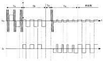
以下、この回路の動作を、図32の波形図を用いて説明する。高圧放電灯DLが非点灯時、降圧チョッパ回路3は、高圧放電灯DLを良好に始動させるため、高圧放電灯DLの安定点灯時の電圧よりも高い直流電圧を出力し、インバータ回路4により、矩形波交流電圧に変換して、始動パルス発生回路を介して、高圧放電灯DLに印加する。 The operation of this circuit will be described below with reference to the waveform diagram of FIG. When the high-pressure discharge lamp DL is not lit, the step-down
始動パルス発生回路においては、コンデンサC7は、パルストランスT1の1次巻線N1、抵抗R7を介して充電される。ここで、電圧応答型のスイッチング素子Q7には、インバータ回路4の出力電圧とコンデンサC7の電圧Vc7の和が印加されることとなるが、インバータ回路4の出力電圧値は、降圧チョッパ回路3の出力電圧値とほぼ同じであり、降圧チョッパ回路3の出力電圧をVc2とすると、矩形波の安定時には、|Vc2|−|Vc7|となり、スイッチング素子Q7のオン電圧には達せず、スイッチング素子Q7はオンしない。しかしながら、矩形波電圧の極性が反転すると、コンデンサC7の電圧は、抵抗R7を介しているため、急速には変化せず、|Vc2|+|Vc7|の電圧がスイッチング素子Q7に印加され、スイッチング素子Q7のオン電圧に達し、スイッチング素子Q7をオンさせる。 In the starting pulse generating circuit, the capacitor C7 is charged via the primary winding N1 and the resistor R7 of the pulse transformer T1. Here, the sum of the output voltage of the
これにより、降圧チョッパ回路3の出力に接続されたコンデンサC2および始動パルス発生回路のコンデンサC7を電源として、パルストランスT1の1次巻線N1には、急峻なパルス電流が流れ、2次巻線N2には、1次巻線N1に発生する電圧を巻数比倍した高電圧が発生し、高圧放電灯DLに印加され、高圧放電灯DLを絶縁破壊する。 As a result, a steep pulse current flows through the primary winding N1 of the pulse transformer T1 using the capacitor C2 connected to the output of the step-
高圧放電灯DLが始動すると、点灯判別手段7aにより、高圧放電灯DLが始動したことを検出し、降圧チョッパ出力検出部7dにより、降圧チョッパ回路3の出力電圧を検出し、出力電圧に応じた所定の電流となるように降圧チョッパ制御回路部8によりスイッチング素子Q2を制御し、インバータ回路4を介して高圧放電灯DLに矩形波状の適正な電力を供給し、安定に点灯する。 When the high pressure discharge lamp DL is started, it is detected by the lighting discriminating means 7a that the high pressure discharge lamp DL has been started, the output voltage of the step-down
高圧放電灯DLは、寿命末期の異常状態の一つとして、片側の電極からのみ放電が形成される、もしくは、片側の電極からの放電が抑制されることにより、放電が非対称状態となる、いわゆる「半波放電」の状態となることが知られている。「半波放電」となると、正常な点灯制御が行なえないため、高圧放電灯点灯装置の異常な発熱や、高圧放電灯点灯装置を構成する電子部品への電気的なストレスの増加の問題が生じる恐れがあるため、半波放電検出回路部6を設け、高圧放電灯DLが半波放電となったことを検出すると、バラストの動作を停止する保護機能を有する高圧放電灯点灯装置が提供されている。 The high-pressure discharge lamp DL is a so-called abnormal state at the end of its life, in which discharge is formed only from one electrode or the discharge from the one electrode is suppressed, so that the discharge becomes asymmetric. It is known to be in a “half wave discharge” state. When “half-wave discharge” occurs, normal lighting control cannot be performed, which causes problems such as abnormal heat generation of the high-pressure discharge lamp lighting device and an increase in electrical stress on the electronic components constituting the high-pressure discharge lamp lighting device. Therefore, a high-pressure discharge lamp lighting device having a protection function for stopping the operation of the ballast is provided when the half-wave discharge
図33に、図31に示す高圧放電灯点灯装置における、半波放電検出による保護機能の動作図を示す。図31中の半波放電検出回路部6により、降圧チョッパ回路3の出力電圧の変動を検出することで、半波放電現象を検出し、半波放電と判定されると、降圧チョッパ制御回路部8からスイッチング素子Q2への制御信号を停止することにより、高圧放電灯DLへの電力供給を停止する。 FIG. 33 shows an operation diagram of a protection function by half-wave discharge detection in the high-pressure discharge lamp lighting device shown in FIG. A half-wave discharge phenomenon is detected by detecting a change in the output voltage of the step-down
従来例では、始動過程では誤検出を防止するために半波放電の検出機能を停止させており、高圧放電灯DLが安定点灯状態に移行した後に検出動作を開始し、半波放電を検出すると、点灯装置の出力を停止または低減する保護動作に移行させる。 In the conventional example, the detection function of half-wave discharge is stopped in the starting process to prevent false detection, and the detection operation is started after the high-pressure discharge lamp DL shifts to a stable lighting state, and half-wave discharge is detected. Then, the operation is shifted to a protection operation for stopping or reducing the output of the lighting device.
(従来例3)
図35は特許文献1(特開2005−100829号公報)に開示された高圧放電灯点灯装置の回路図である。直流電源回路2にはコンデンサCe1,Ce2の直列回路とスイッチング素子Q5,Q6の直列回路が並列に接続されている。コンデンサCe1,Ce2の接続点とスイッチング素子Q5,Q6の接続点の間には、インダクタL2とコンデンサC2の直列回路が接続されている。コンデンサC2の両端には始動回路5のパルストランスPTの2次巻線を介して高圧放電灯DLが接続されている。スイッチング素子Q5,Q6はMOSFETよりなり、逆並列ダイオードを内蔵している。ダイオードD9とスイッチング素子Q9及びインダクタL9よりなる補助チョッパ回路9が付加されている。(Conventional example 3)
FIG. 35 is a circuit diagram of a high pressure discharge lamp lighting device disclosed in Patent Document 1 (Japanese Patent Laid-Open No. 2005-100829). A series circuit of capacitors Ce1 and Ce2 and a series circuit of switching elements Q5 and Q6 are connected to the DC
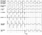
図36は非点灯から点灯に至るまでの各部の動作波形である。スイッチング素子Q5,Q6,Q9に与えられる制御信号は、図36に示すような動作波形となっている。 FIG. 36 shows operation waveforms of respective parts from non-lighting to lighting. The control signal given to switching elements Q5, Q6, Q9 has an operation waveform as shown in FIG.
スイッチング素子Q5,Q6は制御回路71から出力される制御信号により駆動回路72を介してオン・オフ制御される。安定点灯時において、第1の期間T1ではスイッチング素子Q5が高周波でオン・オフされて、スイッチング素子Q6はオフしている。第2の期間T2ではスイッチング素子Q6が高周波でオン・オフされて、スイッチング素子Q5はオフしている。コンデンサCe1,Ce2は十分に容量が大きく、期間T1,T2の交番周期では、コンデンサCe1の電圧Vce1、コンデンサCe2の電圧Vce2は変動しない。直流電源回路2の電圧VdcはコンデンサCe1,Ce2により分圧され、Vdc=Vce1+Vce2であるが、コンデンサCe1,Ce2の容量が略等しい場合、Vce1≒Vce2となる。 The switching elements Q5 and Q6 are on / off controlled via the
第1の期間T1において、スイッチング素子Q5がオンすると、コンデンサCe1→スイッチング素子Q5→インダクタL2→コンデンサC2(始動回路5、高圧放電灯DL)→コンデンサCe1の経路で電流が流れる。スイッチング素子Q5がオフすると、インダクタL2の蓄積エネルギーにより、インダクタL2→コンデンサC2(始動回路5、高圧放電灯DL)→コンデンサCe2→スイッチング素子Q6(の逆並列ダイオード)→インダクタL2の経路で電流が流れる。 When the switching element Q5 is turned on in the first period T1, a current flows through the path of the capacitor Ce1, the switching element Q5, the inductor L2, the capacitor C2 (starting
第2の期間T2において、スイッチング素子Q6がオンすると、コンデンサCe2→コンデンサC2(高圧放電灯DL、始動回路5)→インダクタL2→スイッチング素子Q6→コンデンサCe2の経路で電流が流れる。スイッチング素子Q6がオフすると、インダクタL2の蓄積エネルギーにより、インダクタL2→スイッチング素子Q5(の逆並列ダイオード)→コンデンサCe1→コンデンサC2(高圧放電灯DL、始動回路5)→インダクタL2の経路で電流が流れる。これにより、高圧放電灯DLの電圧Voは安定点灯時には、図36の右側(期間T3よりも後の期間T1,T2)に示すような低周波の矩形波電圧となる。 When the switching element Q6 is turned on in the second period T2, a current flows through a path of the capacitor Ce2 → the capacitor C2 (the high pressure discharge lamp DL, the starting circuit 5) → the inductor L2 → the switching element Q6 → the capacitor Ce2. When the switching element Q6 is turned off, the current in the path of inductor L2 → switching element Q5 (an antiparallel diode thereof) → capacitor Ce1 → capacitor C2 (high-pressure discharge lamp DL, starting circuit 5) → inductor L2 due to the energy stored in the inductor L2. Flowing. Thus, the voltage Vo of the high-pressure discharge lamp DL becomes a low-frequency rectangular wave voltage as shown on the right side of FIG. 36 (periods T1 and T2 after the period T3) during stable lighting.
始動回路5は高圧放電灯DLの非点灯時において、始動用の高圧パルス電圧を発生する。この始動回路5の動作する非点灯時の動作波形を図36の左側(期間T3よりも前)に示す。高圧放電灯DLの非点灯時においては、ランプ電圧Voの振幅はVdc/2となり、これに高圧パルス電圧が重畳されて、ピーク電圧はVpとなる。 The starting
この従来例3によれば、非点灯時および高圧放電灯DLが始動し、アーク放電へ確実に移行するまでの時間において、スイッチング素子Q5のみを高周波でオン/オフし、スイッチング素子Q6はオフしたままにすることでDC始動(DC電圧印加)を行わせることにより半波放電を防止したものである。非点灯状態から点灯状態に移行する際において、半波放電が起こると放電灯DLに対して一方向にしか電流が流れないが、スイッチング素子Q5だけをオン/オフさせると一方向のみしか電流が流れることはないので、立消えが起こる場合はあっても、半波放電の状態となることは防止することができる。 According to the conventional example 3, only the switching element Q5 is turned on / off at a high frequency and the switching element Q6 is turned off during the non-lighting time and the time until the high pressure discharge lamp DL starts and makes a sure transition to arc discharge. The half-wave discharge is prevented by allowing the DC start (DC voltage application) to be performed. In the transition from the non-lighting state to the lighting state, if half-wave discharge occurs, current flows only in one direction with respect to the discharge lamp DL. However, if only the switching element Q5 is turned on / off, current flows only in one direction. Since it does not flow, even if extinction occurs, it is possible to prevent a half-wave discharge state.
図36のランプ電圧Voの波形に示すように、ランプDLが始動しアーク放電へ確実に移行するまでの期間に数十秒から数分間の期間T3を設け、その間も非点灯時に引き続きスイッチング素子Q5だけをオン/オフさせることで放電を安定させ、その後はスイッチング素子Q6もオン/オフさせ、スイッチング素子Q5と交互にスイッチングさせるようにする。 As shown in the waveform of the lamp voltage Vo in FIG. 36, a period T3 of several tens of seconds to several minutes is provided in the period from the start of the lamp DL to the reliable transition to arc discharge. The discharge is stabilized by turning on / off only, and thereafter, the switching element Q6 is also turned on / off to be switched alternately with the switching element Q5.
放電を安定させる期間T3において、スイッチング素子Q5がオンしている間はインダクタL2を通って高圧放電灯DL(及びコンデンサC2)に電流I1が流れ、インダクタL1にエネルギーが蓄えられる。そしてスイッチング素子Q5がオフしているときはインダクタL2に蓄えられていたエネルギーが放出されコンデンサCe2、スイッチング素子Q6の寄生ダイオード、インダクタL2を通って高圧放電灯DL(及びコンデンサC2)に電流I1’が流れる。そのときコンデンサCe2にコンデンサCe1から放出されたエネルギーが印加される。 In the period T3 during which the discharge is stabilized, while the switching element Q5 is on, the current I1 flows through the inductor L2 to the high-pressure discharge lamp DL (and the capacitor C2), and energy is stored in the inductor L1. When the switching element Q5 is off, the energy stored in the inductor L2 is released, and the current I1 ′ flows to the high-pressure discharge lamp DL (and the capacitor C2) through the capacitor Ce2, the parasitic diode of the switching element Q6, and the inductor L2. Flows. At that time, the energy released from the capacitor Ce1 is applied to the capacitor Ce2.
しかしながら、期間T3においてはスイッチング素子Q5のみしか駆動させていないので、DC始動を行わせるとコンデンサCe2に溜まったエネルギーを放出する経路がないため、コンデンサCe2に電圧が溜まる一方となる。そこで、図35の回路では点線に示すような補助チョッパ回路9を設置してコンデンサCe2に充電されるエネルギーの放出経路を設けている。 However, since only the switching element Q5 is driven in the period T3, there is no path for discharging the energy accumulated in the capacitor Ce2 when the DC start is performed, so that the voltage is only accumulated in the capacitor Ce2. Therefore, in the circuit of FIG. 35, an
図35に示すような補助チョッパ回路9を追加することによって、コンデンサCe2に蓄えられた電圧が所定値を超えるとスイッチング素子Q9がオンし、コンデンサCe2に充電されたエネルギーが放電され、スイッチング素子Q9を通ってインダクタL9にエネルギーが蓄えられる。次にスイッチング素子Q9がオフするとインダクタL9に蓄えられたエネルギーが放出され、ダイオードD9を通ってコンデンサCe1に充電される。このとき、スイッチング素子Q9は高周波でオン/オフさせている。これによりコンデンサCe2に溜まるエネルギーを放出でき、過電圧印加を防止できる。
「半波放電」現象は、先述の寿命末期だけではなく、高圧放電灯DLの始動時においても、発生することが知られている。図34は、始動時に発生する「半波放電」を示す波形であり、図34(a)は従来例1(図29の回路)における始動時の「半波放電」の一例を示す波形であり、図34(b),(c)は、従来例2(図31の回路)における始動時の「半波放電」の一例を示す波形であり、(a),(b)は半波放電継続後、通常の両波での放電に移行した場合、(c)は半波放電を継続している場合を示している。 It is known that the “half-wave discharge” phenomenon occurs not only at the end of the aforementioned life but also at the start of the high-pressure discharge lamp DL. FIG. 34 is a waveform showing “half-wave discharge” generated at the time of starting, and FIG. 34 (a) is a waveform showing an example of “half-wave discharging” at the time of starting in Conventional Example 1 (circuit of FIG. 29). 34 (b) and 34 (c) are waveforms showing an example of “half-wave discharge” at the time of start-up in Conventional Example 2 (circuit of FIG. 31), and (a) and (b) are half-wave discharge continuations. After that, when shifting to normal both-wave discharge, (c) shows a case where half-wave discharge is continued.
「半波放電」は、電流が流れる方向の電極が陽極、他方が陰極として作用し、陰極サイクルにある片方の電極がグロー放電からアーク放電に移行できないことにより引き起こされ、電極からの熱電子放出の不安定性に起因しており、この原因としては、電極温度が低い、あるいは、不純物の付着などが考えられる。 “Half-wave discharge” is caused by the fact that the electrode in the direction of current flow acts as the anode and the other as the cathode, and one of the electrodes in the cathode cycle cannot shift from glow discharge to arc discharge. This can be attributed to low electrode temperature or the adhesion of impurities.
始動時の「半波放電」は、図34(a),(b)に示すように、定常点灯に至る過程での現象であるため、先述の半波放電検出回路部6による検出によりバラストの動作を停止させる保護機能を動作させると、高圧放電灯DLが点灯しないという不具合を生じるため、高圧放電灯DLの始動からの一定時間は、先述の保護動作の機能を停止させている。 As shown in FIGS. 34 (a) and 34 (b), the “half-wave discharge” at the time of start-up is a phenomenon in the process of steady lighting, so that the ballast is detected by detection by the half-wave discharge
半波放電を回避する手段として、特許文献1(特開2005−100829号公報)では、図35および図36のような高圧放電灯点灯装置が示され、高圧放電灯DLが始動し、アーク放電へ確実に移行するまでの期間T3において、DC電圧印加となるよう、スイッチング素子を制御することにより、半波放電を防止したものが示されているが、補助チョッパ回路9が付加され、部品点数が増加する。また、DC電圧印加となり、アーク放電へ確実に移行すると、高圧放電灯の発光管の温度が上昇し、両側の電極から電子が放出されやすくなり、安定な点灯に移りやすくなるが、DC電圧印加状態では、片方の電極が陽極、反対の電極が陰極として固定されており、その継続時間によっては、両電極間の状態に差を生じやすく、半波放電の発生を確実に抑えるDC電圧印加時間は、高圧放電灯の種類や状態により変化し、これを適切に設定することは非常に難しい。 As means for avoiding half-wave discharge, Patent Document 1 (Japanese Patent Laid-Open No. 2005-100829) shows a high-pressure discharge lamp lighting device as shown in FIGS. 35 and 36, and the high-pressure discharge lamp DL is started and arc discharge is performed. In the period T3 until the transition to steadily, the switching element is controlled so that the DC voltage is applied so that half-wave discharge is prevented. However, an
また、「半波放電」が継続すると、両電極間の状態に差が生じ、安定な両波の放電に移行しにくくなり、さらに、片側のアーク放電により、高圧放電灯の発光管内部の蒸気圧が高くなり、「半波放電」を維持することも難しくなり、立消えを生じて、非点灯状態に戻るが、発光管内部が高温・高圧となっていることから、いわゆる再始動モードとなり、再び始動させるには、発光管内部の温度・圧力が低下するまで待たなければならず、始動に時間を要するという課題がある。 In addition, if the “half-wave discharge” continues, there will be a difference in the state between the two electrodes, and it will be difficult to shift to a stable double-wave discharge. The pressure increases and it becomes difficult to maintain the “half-wave discharge”, and it goes off and returns to the non-lighting state, but since the inside of the arc tube is at a high temperature and high pressure, it becomes a so-called restart mode, In order to start again, it is necessary to wait until the temperature and pressure inside the arc tube decrease, and there is a problem that it takes time to start.
本発明は、上記課題に鑑みてなされたものであり、高圧放電灯の始動時に半波放電が発生した場合に、速やかに両波の適切な放電に移行させることができる高圧放電灯点灯装置を提供することを目的とする。 The present invention has been made in view of the above problems, and provides a high pressure discharge lamp lighting device capable of promptly shifting to an appropriate discharge of both waves when a half wave discharge occurs at the start of the high pressure discharge lamp. The purpose is to provide.
本発明にあっては、上記の課題を解決するために、図1〜図4に示すように、少なくとも直流電源回路2と、直流電源回路2からの出力を電力変換し、矩形波交流出力として高圧放電灯DLに供給する電力供給回路Pと、始動用の高電圧を高圧放電灯DLに印加する始動回路5と、それらを制御する制御回路7と、前記矩形波交流出力の一方の極性と他方の極性の負荷電圧又は負荷電流が非対称の状態である半波放電を検出する半波放電検出回路6とを備えた高圧放電灯点灯装置において、前記半波放電検出回路6は、高圧放電灯DLが絶縁破壊した後、その高圧放電灯DLの略定格ランプ電圧に達するまでの始動初期に、異なる極性の電圧差もしくは電流差の絶対値が、正常点灯時における矩形波交流出力の各半周期の電圧差もしくは電流差の最大ばらつき値よりも大きいことが検出された場合に半波放電現象であると判別し、前記制御回路7は、前記半波放電検出回路6により半波放電現象であると判別されると、一定期間高圧放電灯DLを消灯させ、その後、再始動させる時に、前記直流電源回路2または電力供給回路Pまたは始動回路5のうち少なくとも1つの出力を調整することにより、負荷電圧の高い極性の矩形波半周期の電圧値もしくは電流値を負荷電圧の低い極性の矩形波半周期の電圧値もしくは電流値に近づける半波改善制御を実施することを特徴とするものである。 In the present invention, in order to solve the above-mentioned problem, as shown in FIGS. 1 to 4, at least the DC
請求項2の発明は、請求項1の発明において、前記半波放電検出回路は、半波放電条件が連続で複数回検出された場合に半波放電現象であると判別することを特徴とする(図7)。 According to a second aspect of the invention, in the first aspect of the invention, the half-wave discharge detection circuit determines that the half-wave discharge phenomenon is a half-wave discharge phenomenon when the half-wave discharge condition is continuously detected a plurality of times. (FIG. 7).
請求項3の発明は、請求項1の発明において、前記半波放電検出回路は、累積検出回数が所定値以上の場合に半波放電現象であると判別することを特徴とする(図8)。 The invention of
請求項4の発明は、請求項1の発明において、前記半波放電検出回路は、所定時間における半波発生割合が所定値以上の場合に半波放電現象であると判別することを特徴とする(図8)。 According to a fourth aspect of the present invention, in the first aspect of the invention, the half-wave discharge detection circuit determines that the half-wave discharge phenomenon occurs when a half-wave generation ratio in a predetermined time is equal to or greater than a predetermined value. (FIG. 8).
請求項5の発明は、請求項1の発明において、前記半波放電検出回路は、高圧放電灯が始動した後、所定時間経過した時点で、半波放電条件を判別することを特徴とする(図5)。 The invention of
請求項6の発明は、請求項5の発明において、半波放電現象の判別をなす所定時間は、高圧放電灯消灯後の再始動動作において、高圧放電灯が即時に始動可能な時間としたことを特徴とする(図5)。 In the invention of
請求項7の発明は、請求項1〜6の発明において、前記半波放電検出回路が半波放電条件を満たし半波放電現象と判別した場合、前記制御回路は一定期間高圧放電灯を消灯させる前に、始動促進制御(図9〜図12の半波放電抑制のための制御期間Tc)を行うことを特徴とする。 According to a seventh aspect of the present invention, in the first to sixth aspects of the invention, when the half-wave discharge detection circuit satisfies the half-wave discharge condition and is determined as a half-wave discharge phenomenon, the control circuit turns off the high-pressure discharge lamp for a certain period. Prior to this, start promotion control (control period Tc for suppressing half-wave discharge in FIGS. 9 to 12) is performed.
請求項8の発明は、請求項7の発明において、消灯前の始動促進制御とは、半波放電検出時に負荷電圧の高かった極性に対し、前記始動回路により高電圧を印加することを特徴とする(図9の期間Tc)。 The invention of
請求項9の発明は、請求項7の発明において、消灯前の始動促進制御とは、半波放電検出時に負荷電圧の高かった極性に対し、前記始動回路により高周波高電圧を重畳することを特徴とする(図10の期間Tc)。 According to a ninth aspect of the present invention, in the seventh aspect of the invention, the start acceleration control before turning off is characterized in that a high frequency high voltage is superimposed by the starter circuit on the polarity having a high load voltage when half-wave discharge is detected. (Period Tc in FIG. 10).
請求項10の発明は、請求項7の発明において、消灯前の始動促進制御とは、半波放電検出時に負荷電圧の高かった極性のみ電力供給回路による矩形波交流出力の半周期を通常より長くすることを特徴とする(図12の期間Tc)。 According to a tenth aspect of the present invention, in the seventh aspect of the invention, the start acceleration control before turning off means that the half cycle of the rectangular wave AC output by the power supply circuit is set longer than usual only in the polarity where the load voltage is high at the time of detecting the half wave discharge. (Period Tc in FIG. 12).
請求項11の発明は、請求項7の発明において、消灯前の始動促進制御とは、半波放電検出時に負荷電圧の高かった極性のみ供給電流が増加するよう、前記電力供給回路を制御することを特徴とする(図11の期間Tc)。 According to an eleventh aspect of the present invention, in the seventh aspect of the invention, the start acceleration control before turning off means that the power supply circuit is controlled so that the supply current increases only in the polarity with a high load voltage when half-wave discharge is detected. (Period Tc in FIG. 11).
請求項12の発明は、請求項1〜6の発明において、前記制御回路は、前記半波放電検出回路により半波放電現象であると判別されると、少なくとも半波放電検出時に負荷電圧の低かった極性の矩形波半周期を含む一定期間高圧放電灯を消灯させることを特徴とする(図13、図14の期間Td)。 According to a twelfth aspect of the present invention, in the first to sixth aspects of the invention, when the half-wave discharge phenomenon is detected by the half-wave discharge detection circuit, the control circuit has a low load voltage at least when half-wave discharge is detected. The high-pressure discharge lamp is extinguished for a certain period including a rectangular wave half cycle with a polarity (period Td in FIGS. 13 and 14).
請求項13の発明は、請求項12の発明において、前記制御回路は、前記半波放電検出回路により半波放電現象であると判別されると、負荷電圧の高い極性の矩形波半周期が終了した時点から矩形波半周期の期間、高圧放電灯への電力供給を停止することを特徴とする(図14の期間Td)。 According to a thirteenth aspect of the present invention, in the twelfth aspect of the present invention, when the control circuit determines that the half-wave discharge phenomenon is caused by the half-wave discharge detection circuit, the rectangular wave half-cycle with a high load voltage is terminated. The power supply to the high-pressure discharge lamp is stopped for a period of a rectangular wave half cycle from the point of time (period Td in FIG. 14).
請求項14の発明は、請求項12の発明において、前記制御回路は、前記半波放電検出回路により半波放電現象であると判別されると、矩形波の一周期にわたり高圧放電灯への電力供給を停止することを特徴とする(図13の期間Td)。 According to a fourteenth aspect of the present invention, in the twelfth aspect of the present invention, when the half-wave discharge detection circuit determines that the control circuit is a half-wave discharge phenomenon, the power to the high-pressure discharge lamp over one cycle of the rectangular wave The supply is stopped (period Td in FIG. 13).
請求項15の発明は、請求項1〜6の発明において、再始動時の半波改善制御は、半波放電検出時に負荷電圧の高かった極性の矩形波半周期、もしくは半波放電検出時に負荷電圧の高かった極性の矩形波半周期の前に行なうことを特徴とする(図15〜図21の半波放電回避期間Te)。 According to a fifteenth aspect of the present invention, in the first to sixth aspects of the invention, the half-wave improvement control at the time of restarting is a rectangular wave half-cycle having a high load voltage at the time of detecting the half-wave discharge, or a load at the time of detecting the half-wave discharge. It is performed before the half-cycle of the rectangular wave having a high voltage (half-wave discharge avoidance period Te in FIGS. 15 to 21).
請求項16の発明は、請求項15の発明において、再始動時の半波改善制御として、半波放電検出時に負荷電圧の高かった極性に対してのみ、前記始動回路により始動用高電圧を印加することを特徴とする(図15の期間Te)。 According to a sixteenth aspect of the invention, in the fifteenth aspect of the invention, as the half-wave improvement control at the time of restart, a high voltage for starting is applied by the starting circuit only to the polarity having a high load voltage when half-wave discharge is detected. (Period Te in FIG. 15).
請求項17の発明は、請求項15の発明において、再始動時の半波改善制御として、始動用高電圧を印加する期間と、半波放電検出時に負荷電圧の高かった極性の矩形波半周期に電力を供給する期間の一連の動作期間を複数回設けることを特徴とする(図16、図17の期間Te)。 According to a seventeenth aspect of the present invention, in the invention of the fifteenth aspect, as a half-wave improvement control at the time of restart, a period during which a high voltage for starting is applied and a rectangular wave half-cycle having a high load voltage at the time of detecting a half-wave discharge A series of operation periods in which power is supplied to is provided a plurality of times (period Te in FIGS. 16 and 17).
請求項18の発明は、請求項15の発明において、再始動時の半波改善制御として、ある一定期間、半波放電検出時に負荷電圧の高かった極性のみ、電力供給回路による矩形波交流出力の半周期を通常より長くすることを特徴とする(図18、図19の期間Te)。 According to an eighteenth aspect of the present invention, in the fifteenth aspect of the invention, as a half-wave improvement control at the time of restart, only a polarity having a high load voltage at the time of detecting a half-wave discharge for a certain period, The half cycle is longer than usual (period Te in FIGS. 18 and 19).
請求項19の発明は、請求項15の発明において、再始動時の半波改善制御として、ある一定期間、半波放電検出時に負荷電圧の高かった極性のみ、供給電流が増加するように前記電力供給回路を制御することを特徴とする(図20の期間Te)。 According to a nineteenth aspect of the present invention, in the fifteenth aspect of the present invention, as the half-wave improvement control at the time of restart, the electric power is increased so that the supply current increases only for a certain period of time when the load voltage is high at the half-wave discharge detection. The supply circuit is controlled (period Te in FIG. 20).
請求項20の発明は、請求項15の発明において、再始動時の半波改善制御として、ある一定期間、半波放電検出時に負荷電圧の高かった極性のみ、電力供給回路の出力電圧を上昇させるように制御することを特徴とする(図20の期間Te)。 According to a twentieth aspect of the invention, in the fifteenth aspect of the invention, as the half-wave improvement control at the time of restarting, the output voltage of the power supply circuit is increased only for a certain period of time when the load voltage is high when the half-wave discharge is detected. Control is performed as described above (period Te in FIG. 20).
請求項21の発明は、請求項20の発明において、電力供給回路の出力電圧を上昇させるように前記直流電源回路の直流出力電圧を上昇させることを特徴とする(図20の期間Te)。 The invention of claim 21 is characterized in that, in the invention of claim 20, the DC output voltage of the DC power supply circuit is increased so as to increase the output voltage of the power supply circuit (period Te in FIG. 20).
請求項22の発明は、請求項1〜6の発明において、再始動時の半波改善制御は、半波放電検出時に負荷電圧の低かった極性の矩形波半周期に行うことを特徴とする(図22〜図26の半波放電回避期間Te)。 According to a twenty-second aspect of the present invention, in the first to sixth aspects of the invention, the half-wave improvement control at the time of restarting is performed in a half-cycle of a rectangular wave having a polarity with a low load voltage when a half-wave discharge is detected ( The half-wave discharge avoidance period Te in FIGS.
請求項23の発明は、請求項22の発明において、再始動時の半波改善制御として、ある一定期間、半波放電検出時に負荷電圧の低かった極性のみ、電力供給回路による矩形波交流出力の半周期を通常より短くすることを特徴とする(図22、図23の期間Te)。 According to a twenty-third aspect of the invention of the twenty-second aspect, as the half-wave improvement control at the time of restart, only the polarity at which the load voltage was low at the time of detecting the half-wave discharge for a certain period of time, The half cycle is shorter than usual (period Te in FIGS. 22 and 23).
請求項24の発明は、請求項22の発明において、再始動時の半波改善制御として、ある一定期間、半波放電検出時に負荷電圧の低かった極性のみ、供給電流が減少するように前記電力供給回路を制御することを特徴とする(図25、図26の期間Te)。 According to a twenty-fourth aspect of the invention, in the invention of the twenty-second aspect, as the half-wave improvement control at the time of restart, the power is reduced so that the supply current decreases only for a certain period of time when the load voltage is low when the half-wave discharge is detected. The supply circuit is controlled (period Te in FIGS. 25 and 26).
請求項25の発明は、請求項22の発明において、再始動時の半波改善制御として、ある一定期間、半波放電検出時に負荷電圧の低かった極性のみ、電力供給回路の出力電圧を減少させるように制御することを特徴とする(図24の期間Te)。 According to a twenty-fifth aspect of the invention of the twenty-second aspect, as the half-wave improvement control at the time of restarting, the output voltage of the power supply circuit is decreased only for a certain period of time when the load voltage is low at the time of half-wave discharge detection. Control is performed as described above (period Te in FIG. 24).
請求項26の発明は、請求項25の発明において、電力供給回路の出力電圧を減少させるように前記直流電源回路2の直流出力電圧Vdcを減少させることを特徴とする(図24の期間Te)。 The invention of claim 26 is characterized in that, in the invention of claim 25, the DC output voltage Vdc of the DC
請求項27の発明は、請求項1〜26のいずれかの発明において、再始動時の半波改善制御として、ある一定期間、電力供給回路における矩形波交流出力周波数を、少なくとも前記半波放電検出時の矩形波交流出力周波数よりも高くすることを特徴とする(図27の期間Te)。 According to a twenty-seventh aspect of the present invention, in the invention according to any one of the first to twenty-sixth aspects, as the half-wave improvement control at the time of restart, at least the half-wave discharge detection is performed for a certain period of time when the rectangular wave AC output frequency in the power supply circuit is It is characterized by being higher than the rectangular wave AC output frequency at the time (period Te in FIG. 27).
請求項28の発明は、請求項1〜27のいずれかに記載の高圧放電灯点灯装置を具備したことを特徴とする照明器具である(図28)。 A twenty-eighth aspect of the present invention is a lighting fixture comprising the high pressure discharge lamp lighting device according to any of the first to twenty-seventh aspects (FIG. 28).
本発明によれば、半波放電検出回路は、高圧放電灯が絶縁破壊した後、その高圧放電灯の略定格ランプ電圧に達するまでの始動初期に、異なる極性の電圧差もしくは電流差の絶対値が、正常点灯時における矩形波交流出力の各半周期の電圧差もしくは電流差の最大ばらつき値よりも大きいことが検出された場合に半波放電現象であると判別し、前記制御回路は、前記半波放電検出回路により半波放電現象であると判別されると、一定期間高圧放電灯を消灯させ、その後、再始動させる時に、前記直流電源回路または電力供給回路または始動回路のうち少なくとも1つの出力を調整することにより、負荷電圧の高い極性の矩形波半周期の電圧値と負荷電圧の低い極性の矩形波半周期の電圧値とを近づける半波改善制御を実施することにより、陰極サイクルとなる電極からの放電を促進するようにしたから、始動過程における半波放電現象の継続を防止して、安定点灯モードに速やかに移行させることができる効果がある。 According to the present invention, the half-wave discharge detection circuit has an absolute value of a voltage difference or a current difference of different polarities at the start of the high voltage discharge lamp after the dielectric breakdown until reaching a substantially rated lamp voltage of the high pressure discharge lamp. Is determined to be a half-wave discharge phenomenon when it is detected that it is larger than the maximum variation value of the voltage difference or current difference of each half cycle of the rectangular wave AC output during normal lighting, the control circuit, When it is determined by the half-wave discharge detection circuit that the half-wave discharge phenomenon has occurred, when the high-pressure discharge lamp is turned off for a certain period and then restarted, at least one of the DC power supply circuit, the power supply circuit, or the starting circuit is used. By adjusting the output, the half-wave improvement control is performed by bringing the voltage value of the rectangular wave half cycle with a high load voltage close to the voltage value of the rectangular wave half cycle with a low load voltage. It is so arranged to facilitate the discharge from the electrode to be the cycle, to prevent the continuation of the half-wave discharge phenomenon in a startup process, there is an effect that it is possible to quickly shift to a stable lighting mode.
(実施形態1)
図1に本発明の実施形態1の点灯装置の回路図を示す。交流電源1は整流器DBにより全波整流され、直流電源回路2により直流電圧Vdcに変換される。直流電源回路2は、インダクタL1とスイッチング素子Q1とダイオードD1とコンデンサC1よりなる昇圧チョッパ回路で構成されている。直流電源回路2のスイッチング素子Q1は制御回路部7により高周波でオン・オフされる。図示はしないが、スイッチング素子Q1の電流やインダクタL1の電流、直流電源回路2の入力電圧、出力電圧は、制御回路部7により監視されており、商用の交流電源1からの交流入力を所定の直流電圧に変換すると共に、入力電流と入力電圧の位相がずれないように回路に抵抗性を持たせる力率改善制御を行うものである。(Embodiment 1)
FIG. 1 shows a circuit diagram of a lighting device according to
直流電源回路2の出力には、高圧放電灯DLへの供給電力を制御する安定器としての電力供給回路Pが接続されている。図1では、電力供給回路Pとして、降圧チョッパ回路3とインバータ回路4を組み合わせた回路構成が用いられているが、従来例で説明したように、降圧チョッパ回路3の機能をインバータ回路4で兼用しても構わない。 Connected to the output of the DC
降圧チョッパ回路3は、スイッチング素子Q2とダイオードD2とインダクタL2とコンデンサC2とからなり、入力電圧を降圧した直流電圧を出力する回路であり、制御回路部7からのPWM信号でスイッチング素子Q2のオン/オフを制御することで高圧放電灯DLへの供給電力を調節する安定器として用いられている。 The step-down
インバータ回路4は、スイッチング素子Q3〜Q6からなるフルブリッジ回路を構成している。このインバータ回路4は、スイッチング素子Q3,Q6のペアとスイッチング素子Q4,Q5のペアが制御回路部7からの制御信号により数十〜数百Hzの低周波で交互にオンされることで、放電灯DLに矩形波交流電力を供給する。また、始動時には共振型の始動回路5の共振周波数付近またはその整数分の1の周波数付近となる数十〜数百kHzの高周波でスイッチング素子Q3,Q6のペアとスイッチング素子Q4,Q5のペアが制御回路部7からの制御信号により交互にオンされることで、高圧放電灯DLに始動用の高電圧を供給する。 The
共振型の始動回路5は、インバータ回路4の出力に接続されたインダクタL3とコンデンサC3のLC直列共振回路よりなり、コンデンサC3と並列に高圧放電灯DLが接続されている。 The resonance-
制御回路部7は、図示しない検出部により高圧放電灯DLのランプ電圧Vo、ランプ電流Io、スイッチング素子Q2の電流、インダクタL2の電流を検出し、これらの検出結果に応じてスイッチング素子Q2のオン/オフ制御を行ない、所望の電流または電力を高圧放電灯DLに供給するように降圧チョッパ回路3のスイッチング素子Q2の制御と、インバータ回路4のスイッチング素子Q3〜Q6の制御を行なう。この制御回路部7は、例えばマイクロコンピュータを含んで構成されている。 The
放電灯DLはメタルハライドランプや高圧水銀ランプのような高輝度高圧放電灯(HIDランプ)である。高圧放電灯は、始動時に絶縁破壊すると、低インピーダンス状態となり、ランプ電圧Voは数Vに低下するが、その後、安定電圧まで数分かけて徐々に上昇し、定格ランプ電圧(数十V〜百数十V)で略一定となり、この状態で点灯を継続する。 The discharge lamp DL is a high-intensity high-pressure discharge lamp (HID lamp) such as a metal halide lamp or a high-pressure mercury lamp. If the high pressure discharge lamp breaks down during start-up, it enters a low impedance state, and the lamp voltage Vo decreases to several volts, but then gradually increases to a stable voltage over several minutes, and the rated lamp voltage (several tens of volts to hundreds of hundreds). It becomes substantially constant at several tens of volts), and lighting is continued in this state.
半波放電検出回路部6は、始動過程(ランプ電圧が徐々に上昇していく過程)における半波放電状態を検出し、始動過程において半波放電状態となると、制御回路部7の動作を半波改善モードに切り替える。 The half-wave discharge
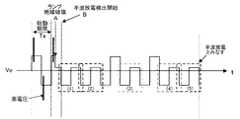
以下、具体的な動作を図2を用いて説明する。まず、商用交流電源1が投入されると、図中の始動期間Taのように、インバータ回路4のスイッチング素子Q3〜Q6は、スイッチング素子Q3とQ6、スイッチング素子Q4とQ5が一対のぺアとなり、高周波で交互にオン・オフ動作し、始動回路5のLC共振動作により高電圧を発生する。その後、インバータ回路4のスイッチング素子Q3〜Q6は低周波で動作し、図2のような低周波の矩形波電圧が高圧放電灯DLの両端に印加される。高圧放電灯DLが点灯に至らない場合は、この動作を繰り替えすことになるが、低周波電圧は、図2のように交互に逆極性で印加されるようにインバータ回路4のスイッチング素子Q3〜Q6は動作する。 A specific operation will be described below with reference to FIG. First, when the commercial
LC共振動作により得られた高電圧により高圧放電灯DLが始動すると、図中のA点のように、高圧放電灯DLの両端電圧が低下する。しかし、高圧放電灯DLの始動直後は放電が不安定であり、半波放電検出期間Tbのように、一方の極性の電圧は低下するが、もう一方の極性の電圧は低下しない状態が起こる。このときのランプ電流Ioの波形を図2の下段に示す。ランプ電流Ioの波形を見ると、一方の極性の電流ともう一方の極性の電流値が異なる状態となっている。この現象を半波放電と呼ぶ。 When the high-pressure discharge lamp DL is started by a high voltage obtained by the LC resonance operation, the voltage across the high-pressure discharge lamp DL decreases as indicated by point A in the figure. However, immediately after the start of the high-pressure discharge lamp DL, the discharge is unstable, and there occurs a state in which the voltage of one polarity decreases but the voltage of the other polarity does not decrease as in the half-wave discharge detection period Tb. The waveform of the lamp current Io at this time is shown in the lower part of FIG. Looking at the waveform of the lamp current Io, the current value of one polarity is different from the current value of the other polarity. This phenomenon is called half-wave discharge.
ここで、図2のランプ電流Ioの波形では、どちらの極性でも電流が流れている状態を示したが、ときには一方の極性の電流が全く流れない状態も存在する。つまり、一方の極性ともう一方の極性の電流もしくは電圧がある設定された電圧値もしくは電流値よりも大きくアンバランスになる状態を半波放電状態とする。要するに、半波放電状態とは、異なる極性の電圧差もしくは電流差の絶対値が、半波放電の判定しきい値よりも大きい状態である。 Here, the waveform of the lamp current Io in FIG. 2 shows a state in which current flows in either polarity, but sometimes there is a state in which current of one polarity does not flow at all. That is, a state in which the current or voltage of one polarity and the other polarity is unbalanced larger than a set voltage value or current value is defined as a half-wave discharge state. In short, the half-wave discharge state is a state where the absolute value of the voltage difference or current difference of different polarities is larger than the determination threshold value for half-wave discharge.
高圧放電灯DLの両端に印加されるランプ電圧Voは、常に半波放電検出回路部6により検出されており、半波放電の状態がある所定時間Tbだけ継続すると、電力変換回路P(降圧チョッパ回路3及びインバータ回路4)は、高圧放電灯DLへの電力供給を停止する。それが、図中の消灯期間Tdである。 The lamp voltage Vo applied to both ends of the high-pressure discharge lamp DL is always detected by the half-wave discharge
消灯期間Tdの経過後、再度、高圧放電灯DLを始動させるために、電力供給回路Pを動作させる。このとき、電力供給回路Pは、再始動期間において、始動用高電圧の印加並びに矩形波半周期の負荷電圧の印加は、好ましくは半波放電検出期間Tbでの負荷電流値の低い方の極性に対してから始めるようにする。 After the extinction period Td has elapsed, the power supply circuit P is operated to start the high-pressure discharge lamp DL again. At this time, during the restart period, the power supply circuit P preferably applies the high voltage for start-up and the load voltage of the rectangular wave half cycle in the polarity with the lower load current value in the half wave discharge detection period Tb. To start with.
このように動作させることにより、消灯期間Tdが経過した後の再始動時には、半波放電現象が発生しにくい状態とすることができ、図2のように高電圧にて高圧放電灯DLがブレークダウンした後、両極性の負荷電圧が共に低下した状態となり、良好な始動性を維持することができる。 By operating in this way, when restarting after the extinguishing period Td has elapsed, the half-wave discharge phenomenon can be made difficult to occur, and the high-pressure discharge lamp DL breaks at a high voltage as shown in FIG. After down, the load voltage of both polarities is in a lowered state, and good startability can be maintained.
この一連の動作により、半波放電を継続させることなく、高圧放電灯DLを再始動させることができる。 By this series of operations, the high-pressure discharge lamp DL can be restarted without continuing the half-wave discharge.
図1の回路図及び図2の波形図では、始動用の高電圧をLC直列共振回路の共振動作により発生させているが、高電圧を発生させる始動回路5の構成はこれに限定されるものではない。 In the circuit diagram of FIG. 1 and the waveform diagram of FIG. 2, the high voltage for starting is generated by the resonance operation of the LC series resonant circuit, but the configuration of the starting
(実施形態1’)
図3は実施形態1の一変形例の回路図である。この回路では、始動回路5の構成が異なり、パルス発生器PGとパルストランスPTの組み合わせで構成されている。パルス発生器PGは、パルストランスPTの1次巻線に印加するパルス電圧を発生させる回路であり、ここでは制御回路部7からの指令により、任意のタイミングで始動用のパルス電圧を発生可能な回路とする。パルス発生器PGの具体的な回路構成については、例えば、極性反転直後にパルス電圧を発生させるのであれば、従来例(図31)と同様の構成でも構わないが、その始動パルス発生用のスイッチング素子Q7のオン・オフは制御回路部7により制御可能としておくと良い。(Embodiment 1 ')
FIG. 3 is a circuit diagram of a modification of the first embodiment. In this circuit, the configuration of the starting
具体的な動作を図4に示す。まず、商用交流電源1が投入されると、図中の始動期間Taのように、インバータ回路4のスイッチング素子Q3〜Q6は、スイッチング素子Q3とQ6、スイッチング素子Q4とQ5が一対のぺアとなり、始動時から低周波で動作し、図4のような低周波の矩形波電圧が高圧放電灯DLの両端に印加される。パルス発生器PGは低周波の矩形波電圧の極性が反転する度にパルス電圧を発生させる。このパルス電圧はパルストランスPTにより昇圧されて、パルストランスPTの2次巻線からコンデンサC2を介して高圧放電灯DLの両端に印加される。高圧放電灯DLが点灯に至らない場合は、この動作を繰り替えすことになるが、低周波電圧の印加は、図2のように交互に逆極性で印加されるようにインバータ回路4のスイッチング素子Q3〜Q6は動作する。 A specific operation is shown in FIG. First, when the commercial
パルス発生動作により得られた高電圧により高圧放電灯DLが始動すると、図中のA点のように、高圧放電灯DLの両端電圧が低下する。しかし、高圧放電灯DLの始動直後は放電が不安定であり、半波放電検出期間Tbのように、一方の極性の電圧は低下するが、もう一方の極性の電圧は低下しない状態が起こる。このときのランプ電流Ioの波形を図4の下段に示す。ランプ電流Ioの波形を見ると、一方の極性の電流ともう一方の極性の電流値が異なる状態となっている。この現象を半波放電と呼ぶ。 When the high-pressure discharge lamp DL is started by the high voltage obtained by the pulse generation operation, the both-ends voltage of the high-pressure discharge lamp DL decreases as indicated by point A in the figure. However, immediately after the start of the high-pressure discharge lamp DL, the discharge is unstable, and there occurs a state in which the voltage of one polarity decreases but the voltage of the other polarity does not decrease as in the half-wave discharge detection period Tb. The waveform of the lamp current Io at this time is shown in the lower part of FIG. Looking at the waveform of the lamp current Io, the current value of one polarity is different from the current value of the other polarity. This phenomenon is called half-wave discharge.
ここで、図4のランプ電流Ioの波形では、どちらの極性でも電流が流れている状態を示したが、ときには一方の極性の電流が全く流れない状態も存在する。つまり、一方の極性ともう一方の極性の電流もしくは電圧がある設定された電圧値もしくは電流値よりも大きくアンバランスになる状態を半波放電とする。要するに、半波放電状態とは、異なる極性の電圧差もしくは電流差の絶対値が、半波放電の判定しきい値よりも大きい状態である。 Here, the waveform of the lamp current Io in FIG. 4 shows a state in which current flows in either polarity, but sometimes there is a state in which current of one polarity does not flow at all. That is, a half-wave discharge is a state in which the current or voltage of one polarity and the other polarity is more imbalanced than a set voltage value or current value. In short, the half-wave discharge state is a state where the absolute value of the voltage difference or current difference of different polarities is larger than the determination threshold value for half-wave discharge.
放電灯DLの両端電圧Voは、常に半波放電検出回路部6により検出されており、半波放電の状態がある所定時間Tbだけ継続すると、電力供給回路Pは、放電灯DLへの電力供給を停止する。それが、図中の消灯期間Tdである。 The voltage Vo between both ends of the discharge lamp DL is always detected by the half-wave discharge
消灯期間Tdの経過後、再度、高圧放電灯DLを始動させるために、電力供給回路Pを動作させる。このとき、電力供給回路Pは、再始動期間において、始動用高電圧の印加並びに矩形波半周期の負荷電圧の印加は、好ましくは半波放電検出期間Tbでの負荷電流値の低い方の極性に対してから始めるようにする。 After the extinction period Td has elapsed, the power supply circuit P is operated to start the high-pressure discharge lamp DL again. At this time, during the restart period, the power supply circuit P preferably applies the high voltage for start-up and the load voltage of the rectangular wave half cycle in the polarity with the lower load current value in the half wave discharge detection period Tb. To start with.
このように動作させることにより、消灯期間Tdが経過した後の再始動時には、半波放電現象が発生しにくい状態とすることができ、図4のように高電圧にて高圧放電灯DLがブレークダウンした後、両極性の負荷電圧が共に低下した状態となり、良好な始動性を維持することができる。 By operating in this way, when restarting after the extinguishing period Td has elapsed, the half-wave discharge phenomenon can be made difficult to occur, and the high-pressure discharge lamp DL breaks at a high voltage as shown in FIG. After down, the load voltage of both polarities is in a lowered state, and good startability can be maintained.
以上の一連の動作により、半波放電を継続させることなく、高圧放電灯DLを再始動させることができる。 With the above series of operations, the high-pressure discharge lamp DL can be restarted without continuing half-wave discharge.
(実施形態2)
実施形態2を図5〜図8を用いて説明する。この実施形態2では半波放電検出期間Tbにおける半波放電の検出の具体的態様について説明する。回路構成は図1または図3と同じで良い。(Embodiment 2)
A second embodiment will be described with reference to FIGS. In the second embodiment, a specific mode of half-wave discharge detection in the half-wave discharge detection period Tb will be described. The circuit configuration may be the same as in FIG. 1 or FIG.
高圧放電灯では始動直後は電極温度の不均一などの原因により、半波放電が見られる。しかし、始動時の半波放電のあと、放電は両極性となり、安定に放電することが一般的である。 In a high-pressure discharge lamp, half-wave discharge is observed immediately after starting due to non-uniform electrode temperature. However, after the half-wave discharge at start-up, the discharge is generally bipolar and is generally discharged stably.
本実施形態では上記のような始動直後の短い間の半波放電を検出しないようにしたものであり、半波放電が継続または、ある程度の時間が経過した後も発生するような状況において精度良く半波放電を検出できるようにしたものである。具体的な動作を図5、図6を用いて説明する。 In the present embodiment, the half-wave discharge is not detected for a short time immediately after the start as described above, and the half-wave discharge is continued in a short period of time or after a certain amount of time has passed. A half-wave discharge can be detected. A specific operation will be described with reference to FIGS.
図5では、高圧放電灯DLの始動期間Taを経て、A点でランプ絶縁破壊の後、半波放電の検出はB点で開始され、その結果、高圧放電灯DLが始動した直後の半波放電(A点〜B点の半波放電)については無視することが可能となる。このときA点〜B点の時間は、半波放電の検出による消灯後の再始動により高圧放電灯DLが直ぐに始動できる程度の時間とする。 In FIG. 5, after the start period Ta of the high pressure discharge lamp DL, after the lamp dielectric breakdown at the point A, the detection of the half wave discharge is started at the point B. As a result, the half wave immediately after the high pressure discharge lamp DL is started. Discharge (half-wave discharge from point A to point B) can be ignored. At this time, the time from the point A to the point B is set to such a time that the high-pressure discharge lamp DL can be started immediately by restart after turning off by detecting half-wave discharge.
図5では、図中の極性(1)と極性(2)の電圧差の絶対値が半波放電の判定しきい値より大きいときに、半波放電と判定する例である。 FIG. 5 shows an example in which half-wave discharge is determined when the absolute value of the voltage difference between polarity (1) and polarity (2) in the drawing is larger than the determination threshold value for half-wave discharge.
図6では、図中の極性(1)と極性(2)の電圧差の絶対値を求めて、一回目の電圧差と二回目の電圧差とで異なったときだけ半波放電とみなすようにした例である。 In FIG. 6, the absolute value of the voltage difference between the polarity (1) and the polarity (2) in the figure is obtained, and only when the first voltage difference and the second voltage difference are different, the half-wave discharge is considered. This is an example.
図7では、半波放電の検出開始(B点)は、高圧放電灯DLの始動直後(ランプが絶縁破壊されたA点の直後)とし、半波放電状態の周期が複数回繰り返されたときに、半波放電とみなすようにした例である。例えば図7では、5回(5周期)の半波放電状態が起こった時点で半波放電とみなしている。 In FIG. 7, the detection start of half-wave discharge (point B) is immediately after the start of the high-pressure discharge lamp DL (immediately after point A where the lamp is dielectrically broken), and the period of the half-wave discharge state is repeated a plurality of times. Furthermore, this is an example in which it is regarded as half-wave discharge. For example, in FIG. 7, half-wave discharge is considered when five (5 cycles) half-wave discharge states occur.
図8では、半波放電の検出開始(B点)は、高圧放電灯DLの始動直後(ランプが絶縁破壊されたA点の直後)とし、ある所定期間内に半波放電状態が起こっている割合が所定の割合を超えた場合に、半波放電とみなすようにした例である。例えば、10周期中に6回以上の割合で半波放電状態の周期があれば、半波放電として検出する。図示された例では、10周期中7回(7周期)、つまり7割の割合で半波放電状態が起こった時点で半波放電とみなしている。 In FIG. 8, the detection start of half-wave discharge (point B) is immediately after the start of the high-pressure discharge lamp DL (immediately after point A where the lamp is dielectrically broken), and a half-wave discharge state occurs within a predetermined period. In this example, when the ratio exceeds a predetermined ratio, it is regarded as half-wave discharge. For example, if there are half-wave discharge state cycles at a rate of 6 or more in 10 cycles, it is detected as half-wave discharge. In the illustrated example, half-wave discharge is considered when the half-wave discharge state occurs 7 times out of 10 cycles (7 cycles), that is, at a rate of 70%.
(実施形態3)
実施形態3を図9を用いて説明する。回路構成は図3と同じで良い。実施形態1および2と比べると、消灯期間Tdの前に半波放電抑制のための制御期間Tcを設けたところが異なる。(Embodiment 3)
A third embodiment will be described with reference to FIG. The circuit configuration may be the same as in FIG. Compared with the first and second embodiments, a difference is that a control period Tc for suppressing half-wave discharge is provided before the extinguishing period Td.
図9の半波放電抑制制御期間Tcの動作は、半波放電検出期間Tbで半波放電と判別されたときに、半波放電検出期間Tbにおける電圧値が大きい方の極性(または電流値が小さい方の極性)に対して、高電圧パルスを印加するように所定期間、始動回路5を動作させるものである。このように動作させることにより、半波放電検出期間Tbで電流が流れにくかった極性を高電圧パルスの印加により電流が流れやすくする。その結果、消灯期間Tdの直前には高圧放電灯DLは放電しやすい状態となっており、消灯期間Tdが経過した後の再始動時に半波放電の発生を抑制することができる。 The operation in the half-wave discharge suppression control period Tc in FIG. 9 is performed when the half-wave discharge detection period Tb determines that the half-wave discharge is the half-wave discharge detection period Tb. The starting
(実施形態4)
実施形態4を図10を用いて説明する。回路構成は図1と同じで良い。実施形態4では、ランプ始動および再始動時の高電圧の印加方法を共振動作とし、さらに半波放電抑制制御期間Tcでは、半波放電検出期間Tbにおける電圧値が大きい方の極性(または電流値が小さい方の極性)に対し、直流電圧が重畳した共振での高電圧を所定時間印加する。このように動作させることにより、始動のための高電圧の発生方法が共振での場合においても半波放電検出期間Tbで電流が流れにくかった極性に対し、高電圧を印加することが可能となり、消灯期間Tdの直前には高圧放電灯DLは放電しやすい状態となっており、再始動時に半波放電の発生を抑制することができる。(Embodiment 4)
A fourth embodiment will be described with reference to FIG. The circuit configuration may be the same as in FIG. In the fourth embodiment, the method of applying a high voltage at the time of starting and restarting the lamp is a resonance operation. Further, in the half-wave discharge suppression control period Tc, the polarity (or current value) having the larger voltage value in the half-wave discharge detection period Tb Is applied for a predetermined time with respect to the smaller polarity). By operating in this way, even when the method of generating a high voltage for starting is resonance, it becomes possible to apply a high voltage to the polarity in which the current was difficult to flow in the half-wave discharge detection period Tb. Immediately before the extinguishing period Td, the high-pressure discharge lamp DL is in a state of being easily discharged, and generation of half-wave discharge can be suppressed during restart.
(実施形態5)
実施形態5を図11を用いて説明する。回路構成は図3と同じで良い。実施形態5では、半波放電抑制制御期間Tcでは、半波放電検出期間Tbにおける電圧値が大きい方の極性(または電流値が小さい方の極性)に対し、電流制御目標値IPrefを通常の基準値より上昇させ、ランプ電流のレべルを引き上げる。(Embodiment 5)
A fifth embodiment will be described with reference to FIG. The circuit configuration may be the same as in FIG. In the fifth embodiment, in the half-wave discharge suppression control period Tc, the current control target value IPref is set to the normal reference with respect to the polarity having the larger voltage value (or the polarity having the smaller current value) in the half-wave discharge detection period Tb. Raise the value of the lamp current and raise the lamp current level.
ここで、電流制御目標値IPrefとは、降圧チョッパ回路3のチョッパ電流のピーク値の目標値である。インダクタL2に流れるチョッパ電流は図示しない検出手段により検出されて制御回路部7に入力されており、制御回路部7はインダクタL2に流れる電流が電流制御目標値IPrefに達すると、降圧チョッパ回路3のスイッチング素子Q2をオフさせる。また、ダイオードD2を介して流れる回生電流がゼロになると、降圧チョッパ回路3のスイッチング素子Q2をオンさせる。電流制御目標値IPrefを上昇させることで、ランプ電流のレベルを引き上げることができる。 Here, the current control target value IPref is a target value of the peak value of the chopper current of the step-down
以上により、温度が低く、電子が飛びにくい方の電極が、消灯期間Tdの直前には温められて、両電極温度が均一化し、再始動時に半波放電の発生を抑制することができる。 As described above, the electrode having a lower temperature and less likely to fly electrons is heated immediately before the extinguishing period Td, the temperature of both electrodes becomes uniform, and the generation of half-wave discharge can be suppressed at the time of restart.
(実施形態6)
実施形態6を図12を用いて説明する。回路構成は図3と同じで良い。実施形態6では、半波放電抑制制御期間Tcでは、半波放電検出期間Tbにおける電圧値が大きい方の極性(または電流値が小さい方の極性)の矩形波半周期を通常よりも長くする。
以上により、温度が低い方の電極が消灯期間Tdの直前には温められて、両電極温度が均一化し、再始動時に半波放電の発生を抑制することができる。(Embodiment 6)
A sixth embodiment will be described with reference to FIG. The circuit configuration may be the same as in FIG. In the sixth embodiment, in the half-wave discharge suppression control period Tc, the rectangular wave half cycle of the polarity with the larger voltage value (or the polarity with the smaller current value) in the half-wave discharge detection period Tb is made longer than usual.
As described above, the electrode having the lower temperature is warmed immediately before the extinguishing period Td, the temperatures of both electrodes are made uniform, and generation of half-wave discharge can be suppressed at the time of restart.
(実施形態7)
実施形態7を図13、図14を用いて説明する。回路構成は図3と同じで良い。本実施形態では、半波放電検出後の動作停止の時間(消灯期間Td)について説明する。(Embodiment 7)
A seventh embodiment will be described with reference to FIGS. The circuit configuration may be the same as in FIG. In the present embodiment, the operation stop time (light-out period Td) after half-wave discharge detection will be described.
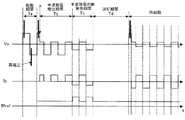
図13に示すように、半波放電検出期間Tbにて半波放電が発生し、半波放電であると判定されたとき(図中C点)に、所定時間の消灯期間Tdに移行し、ある所定時間の消灯後、期間Teの動作に移行する。ここで、ある所定時間の消灯期間Tdとは、半波放電が発生している極性、発生していない極性の両極性を必ず含む時間(少なくとも一周期以上)にすることで、高圧放電灯DLを完全に消灯させることができ、高圧放電灯DLの状態を一旦リセットし、期間Teに移行することができる。 As shown in FIG. 13, when half-wave discharge occurs in the half-wave discharge detection period Tb and it is determined that it is half-wave discharge (point C in the figure), it shifts to a turn-off period Td of a predetermined time, After the light is turned off for a predetermined time, the operation moves to the period Te. Here, the extinguishing period Td of a predetermined time is a time (at least one period or more) that always includes both polarities in which half-wave discharge is generated and polarities in which half-wave discharge is not generated, so that the high-pressure discharge lamp DL Can be completely extinguished, the state of the high-pressure discharge lamp DL can be reset once, and the period Te can be entered.
さらに、図14では、動作停止点Cが図13とは異なる。図14では、半波放電検出期間Tbで半波放電と判定された場合、必ず両極性のうち電圧値が高い極性(または電流値が小さい方の極性)の半周期が経過した時点で消灯期間Tdに移行する。この場合の消灯期間Tdの停止時間は、半周期となる。このようにすることで、必ず電圧値の低い極性(半波放電でない極性)を含むように、動作を停止させることができ、完全に高圧放電灯DLを消灯させることができ、高圧放電灯DLの状態を一旦リセットすることが可能となる。 Further, in FIG. 14, the operation stop point C is different from that in FIG. In FIG. 14, when half-wave discharge is determined in the half-wave discharge detection period Tb, the extinguishing period is always when a half cycle of a polarity having a higher voltage value (or a polarity having a smaller current value) out of both polarities has elapsed. Transition to Td. In this case, the stop time of the turn-off period Td is a half cycle. By doing so, it is possible to stop the operation so as to always include a polarity with a low voltage value (a polarity that is not a half-wave discharge), and it is possible to completely turn off the high-pressure discharge lamp DL. This state can be reset once.
(実施形態8)
実施形態8を図15を用いて説明する。回路構成は図3と同じで良い。本実施形態では、再始動時の半波改善制御である半波放電回避期間Teでの高電圧の印加が、半波放電検出期間Tbにおける電圧値の大きい方の極性(または電流値が小さい方の極性)に対してのみに高電圧を印加し、半波放電検出期間Tbで放電しにくかった方の極性の放電を積極的に促すものである。このように動作させることで、放電しにくかった方の極性に対して、高電圧で始動した直後に矩形波電流を高圧放電灯DLに流すことが可能となり、半波放電の継続を防ぐことが可能となる。(Embodiment 8)
(実施形態9)
実施形態9を図16、図17を用いて説明する。図16は始動のための高電圧を共振動作で発生させる点灯装置(図1)についてのタイムチャートであり、図17は始動のための高電圧をパルス発生動作で発生させる点灯装置(図3)についてのタイムチャートである。
以下、図16を用いて動作を説明するが、図17についても同様の動作である。(Embodiment 9)
A ninth embodiment will be described with reference to FIGS. 16 and 17. FIG. 16 is a time chart of a lighting device (FIG. 1) that generates a high voltage for starting by a resonance operation, and FIG. 17 is a lighting device (FIG. 3) that generates a high voltage for starting by a pulse generating operation. It is a time chart about.
Hereinafter, the operation will be described with reference to FIG. 16, but the same operation is performed for FIG.
高圧放電灯DLの両端電圧は、常に半波放電検出回路部6により検出されており、半波放電がある所定時間Tbだけ継続すると、電力供給回路Pは動作を停止し、高圧放電灯DLへの電力供給を停止する。それが図中の消灯期間Tdである。消灯期間Tdの経過後、再度、高圧放電灯DLを始動させるために、電力供給回路Pを動作させる。このとき、電力供給回路Pは、再始動時の半波改善制御である半波放電回避期間Teにおいて、始動期間Taと同様に高周波動作と低周波動作、停止を図16のように繰り返す。ここで、半波放電回避期間Teにおける電力供給回路Pの低周波動作は、半波放電検出期間Tbで電圧が低下していなかった極性、つまり、放電しにくかった方の極性に対してのみ、ある所定の期間だけ動作させる。 The voltage at both ends of the high-pressure discharge lamp DL is always detected by the half-wave discharge
このように動作させることにより、半波放電検出期間Tbで電流が流れていない方の極性のみに電流を流すことになり、半波放電検出期間Tbで電流が流れなかった方の電極温度を期間Teにおいて上昇させることができる。 By operating in this way, the current flows only in the polarity where the current does not flow in the half-wave discharge detection period Tb, and the electrode temperature in which no current flows in the half-wave discharge detection period Tb It can be raised in Te.
半波放電回避期間Teの経過後、電力供給回路Pは、始動期間Taと同様の動作となり、図のように始動用の高電圧の印加により高圧放電灯DLがブレークダウンした後、両極性の負荷電圧が共に低下した状態となり、良好な始動性を維持することができる。つまり、半波放電回避期間Teにより、半波放電検出期間Tbで電流が流れなかった極性の電極の温度を上昇させることができ、半波放電回避期間Teの経過後に、始動期間Taと同様の動作になったときには、両方の電極温度がほぼ均一になり、半波放電を継続させることなく、高圧放電灯DLを始動させることができる。 After the half-wave discharge avoidance period Te has elapsed, the power supply circuit P operates in the same manner as in the start-up period Ta, and after the high-pressure discharge lamp DL breaks down due to the application of a high voltage for start-up as shown in the figure, Both load voltages are reduced, and good startability can be maintained. That is, the half-wave discharge avoidance period Te can increase the temperature of the electrode of which polarity did not flow during the half-wave discharge detection period Tb, and after the half-wave discharge avoidance period Te has elapsed, When in operation, the temperature of both electrodes becomes substantially uniform, and the high-pressure discharge lamp DL can be started without continuing half-wave discharge.
(実施形態10)
実施形態10を図18、図19を用いて説明する。図19は始動のための高電圧を共振動作で発生させる点灯装置(図1)についてのタイムチャートであり、図18は始動のための高電圧をパルス発生動作で発生させる点灯装置(図3)についてのタイムチャートである。(Embodiment 10)
The tenth embodiment will be described with reference to FIGS. FIG. 19 is a time chart of a lighting device (FIG. 1) that generates a high voltage for starting by a resonance operation, and FIG. 18 is a lighting device (FIG. 3) that generates a high voltage for starting by a pulse generating operation. It is a time chart about.
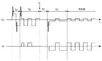
図18において、消灯期間Tdの後、再度、電力供給回路Pを動作させ、高圧放電灯DLを始動させる際に、半波放電検出期間Tbで電流が流れなかった極性の周期を長くし、その極性での電極の温度上昇を大きくさせる。さらに、再度、高圧放電灯DLを始動させるときの高圧パルス電圧の印加は半波放電検出期間Tbで電流が流れなかった極性のみとし、高圧パルス電圧で絶縁破壊し、ランプ電流が流れ出す極性を必ず半波放電検出期間Tbで電流が流れなかった側の極性とする。このように制御することで、2つの電極温度をほぼ均一化させることができ、半波放電の継続を防止することができ、良好な始動性を確保することができる。 In FIG. 18, when the power supply circuit P is operated again after the extinguishing period Td and the high-pressure discharge lamp DL is started, the period of the polarity in which no current flows in the half-wave discharge detection period Tb is lengthened. Increase the temperature rise of the electrode in polarity. Furthermore, when the high-pressure discharge lamp DL is started again, the high-voltage pulse voltage is applied only in the polarity where no current flows in the half-wave discharge detection period Tb. The polarity on the side where no current flows in the half-wave discharge detection period Tb. By controlling in this way, the two electrode temperatures can be made substantially uniform, the continuation of half-wave discharge can be prevented, and good startability can be ensured.
図19は、始動用高電圧をLC共振で発生させる場合の動作波形図である。この場合も図18の場合と同様に、半波放電回避期間Teにおいて、LC共振電圧でランプが始動したとき、期間Tbで電流が流れなかった極性のみ矩形波半周期を通常より長くする。 FIG. 19 is an operation waveform diagram when the high voltage for starting is generated by LC resonance. Also in this case, as in the case of FIG. 18, when the lamp is started at the LC resonance voltage in the half-wave discharge avoidance period Te, the rectangular wave half-cycle is made longer than usual only for the polarity in which no current flows in the period Tb.
(実施形態11)
実施形態11を図20を用いて説明する。回路構成は図3と同じで良い。図3の回路では高圧放電灯DLが不点灯のときは、直流電源回路2の出力電圧Vdcと電力供給回路Pの出力電圧値はほぼ等しくなる。次に、高圧放電灯DLが点灯すると電力供給回路Pの出力電圧はランプ電圧Voと同じになるように回路が動作する。(Embodiment 11)
An eleventh embodiment will be described with reference to FIG. The circuit configuration may be the same as in FIG. In the circuit of FIG. 3, when the high pressure discharge lamp DL is not lit, the output voltage Vdc of the DC
図20において、半波放電検出期間Tbで半波放電が発生しているが、電圧が低下していない方の極性の電圧、つまり高圧放電灯DLが点灯していない極性の電圧はVdcとなる。所定の期間Tbだけ半波放電が継続すると電力供給回路Pは動作を停止する。これが消灯期間Tdである。 In FIG. 20, the half-wave discharge is generated in the half-wave discharge detection period Tb, but the voltage of the polarity where the voltage is not lowered, that is, the voltage of the polarity where the high-pressure discharge lamp DL is not lit is Vdc. . When half-wave discharge continues for a predetermined period Tb, the power supply circuit P stops operating. This is the turn-off period Td.
その消灯期間Tdの経過後、再度、高圧放電灯DLを始動させるための動作に移行するが、図中の半波放電回避期間Teのように、半波放電検出期間Tbで電圧が低下しなかった極性のみ、直流電源回路2の出力電圧Vdcを上昇させ、半波放電検出期間Tbで点灯しにくかった極性を高い印加電圧により放電させやすい状態にする。このような動作にすることにより、直流電源回路2の出力電圧Vdcを常に高い電圧に維持する必要がなく、回路のストレスを低減でき、なおかつ、半波放電の継続を防止することもできる。 After the turn-off period Td has elapsed, the operation again starts to start the high-pressure discharge lamp DL, but the voltage does not decrease in the half-wave discharge detection period Tb, unlike the half-wave discharge avoidance period Te in the figure. The output voltage Vdc of the DC
(実施形態12)
実施形態12を図21を用いて説明する。回路構成は図3と同じで良い。実施形態11とは半波放電回避期間Teの動作のみが違う。本実施形態では、半波放電検出期間Tbにおける一方の極性ともう一方の極性の電圧差を検出し、その電圧差に応じて、半波放電回避期間Teでの直流電源回路2の出力電圧Vdcの上昇幅を設定する。つまり、電圧差が大きいときは、直流電源回路2の出力電圧Vdcの上昇幅を大きくし、電圧差が小さいときは、直流電源回路2の出力電圧Vdcの上昇幅を小さくする。
The twelfth embodiment will be described with reference to FIG. The circuit configuration may be the same as in FIG. Only the operation in the half-wave discharge avoidance period Te is different from the eleventh embodiment. In the present embodiment, a voltage difference between one polarity and the other polarity in the half-wave discharge detection period Tb is detected, and the output voltage Vdc of the DC
このように動作させることにより、さらに回路ストレスを低減することができ、半波放電の継続も防止することができる。 By operating in this way, circuit stress can be further reduced, and continuation of half-wave discharge can be prevented.
(実施形態13)
実施形態13を図22、図23を用いて説明する。図23は始動のための高電圧を共振動作で発生させる点灯装置(図1)についてのタイムチャートであり、図22は始動のための高電圧をパルス発生動作で発生させる点灯装置(図3)についてのタイムチャートである。(Embodiment 13)
The thirteenth embodiment will be described with reference to FIGS. FIG. 23 is a time chart for a lighting device (FIG. 1) that generates a high voltage for starting by a resonant operation, and FIG. 22 is a lighting device (FIG. 3) that generates a high voltage for starting by a pulse generating operation. It is a time chart about.
実施形態10とは期間Teの動作が違う。期間Tdまでの動作は実施形態10と全く同じであるので重複する説明は省略する。図22において、消灯期間Tdの経過後、再度、電力供給回路Pを動作させ、高圧放電灯DLを始動させる際に、半波放電検出期間Tbで電流が多く流れた極性の周期を通常よりも短くし、その極性での電極の温度上昇をできるだけ少なくする。さらに、再度、高圧放電灯DLを始動させる再始動期間での高圧パルス電圧の印加は、半波放電検出期間Tbで電流が流れなかった極性のみとし、高圧パルス電圧で絶縁破壊し、ランプ電流が流れ出す極性を必ず半波放電検出期間Tbで電流が流れなかった極性とする。このようにすることで、2つの電極温度をほぼ均一化させることができ、半波放電の継続を防止することができ、良好な始動性を確保することができる。 The operation in the period Te is different from that in the tenth embodiment. Since the operation up to the period Td is exactly the same as that of the tenth embodiment, a duplicate description is omitted. In FIG. 22, when the power supply circuit P is operated again after the extinguishing period Td has elapsed and the high-pressure discharge lamp DL is started, the period of the polarity in which a large amount of current flows in the half-wave discharge detection period Tb is set to be longer than usual. Keep it short and minimize the temperature rise of the electrode at that polarity. Furthermore, the application of the high-voltage pulse voltage in the restart period for starting the high-pressure discharge lamp DL again is limited to the polarity in which no current flows in the half-wave discharge detection period Tb. The polarity that flows out is always the polarity in which no current flows in the half-wave discharge detection period Tb. By doing in this way, two electrode temperature can be made substantially uniform, continuation of half wave discharge can be prevented, and favorable startability can be ensured.
図23は、高電圧をLC共振で発生する場合の動作波形図である。この場合も図22の場合と同様に、半波放電回避期間Teにおいて、LC共振電圧でランプが始動したときに、半波放電検出期間Tbで電流が多く流れた極性のみ矩形波電圧の半周期を通常よりも短くする。 FIG. 23 is an operation waveform diagram when a high voltage is generated by LC resonance. In this case as well as in the case of FIG. 22, when the lamp is started with the LC resonance voltage in the half-wave discharge avoidance period Te, only the polarity in which a large amount of current flows in the half-wave discharge detection period Tb is a half cycle of the rectangular wave voltage. Is shorter than usual.
(実施形態14)
実施形態14を図24を用いて説明する。回路構成は図3と同じで良い。図3の回路では高圧放電灯DLが不点灯のときは、直流電源回路2の出力電圧Vdcと電力供給回路Pの出力電圧値はほぼ等しくなる。次に、高圧放電灯DLが点灯すると、電力供給回路Pの出力電圧はランプ両端電圧Voと同じになるように回路が動作する。(Embodiment 14)
Embodiment 14 will be described with reference to FIG. The circuit configuration may be the same as in FIG. In the circuit of FIG. 3, when the high pressure discharge lamp DL is not lit, the output voltage Vdc of the DC
図24において、半波放電検出期間Tbで半波放電が発生しているが、電圧が低下していない方の電圧、つまり高圧放電灯DLが点灯していない極性の電圧は、直流電源回路2の出力電圧Vdcとなる。所定の期間Tbだけ半波放電が縦続すると、電力供給回路Pは動作を停止する。これが消灯期間Tdである。その消灯期間Tdの経過後、再度、高圧放電灯DLを始動させるための動作に移行するが、図中、半波放電回避期間Teのように、半波放電検出期間Tbで負荷電圧が低下した極性のみ、直流電源回路2の出力電圧Vdcを減少させ、半波放電検出期間Tbで高圧放電灯DLが点灯しやすかった極性を低い印加電圧により放電させにくい状態にする。このような動作にすることにより、直流電源回路2の出力電圧Vdcを下げることができるので、回路のストレスを低減でき、なおかつ、半波放電の継続を防止することもできる。 In FIG. 24, the half-wave discharge is generated in the half-wave discharge detection period Tb, but the voltage of which the voltage is not lowered, that is, the voltage of the polarity in which the high-pressure discharge lamp DL is not lit is the DC
(実施形態15)
実施形態15を図25を用いて説明する。実施形態11とは半波放電回避期間Teの動作が違う。消灯期間Tdまでの動作は実施形態11と全く同じであるので重複する説明は省略する。図25において、消灯期間Tdの経過後、再度、電力供給回路Pを動作させ、高圧放電灯DLを始動させる際に、半波放電検出期間Tbで電流が流れなかった極性の電流制御目標値IPrefを基準値より上昇させて、熱電子放出開始後の電流レべルを上げる。(Embodiment 15)
Embodiment 15 will be described with reference to FIG. The operation of the half-wave discharge avoidance period Te is different from that of the eleventh embodiment. Since the operation up to the extinguishing period Td is exactly the same as that of the eleventh embodiment, a duplicate description is omitted. In FIG. 25, after the extinction period Td has elapsed, when the power supply circuit P is operated again and the high-pressure discharge lamp DL is started, the current control target value IPref having a polarity in which no current flows in the half-wave discharge detection period Tb. Is raised from the reference value to increase the current level after starting thermionic emission.
以上により、高圧放電灯DLの非対称放電状態を無くして、高圧放電灯DLを早く安定点灯状態へと移行させるため、始動失敗が少なく、始動性の良い高圧放電灯点灯装置を実現することができる。 As described above, since the asymmetric discharge state of the high-pressure discharge lamp DL is eliminated and the high-pressure discharge lamp DL is quickly shifted to the stable lighting state, it is possible to realize a high-pressure discharge lamp lighting device with less start failure and good startability. .
(実施形態16)
実施形態16を図26を用いて説明する。実施形態15とは半波放電回避期間Teの動作が違う。消灯期間Tdまでの動作は実施形態15と全く同じであるので重複する説明は省略する。図26において、消灯期間Tdの経過後、再度、電力供給回路Pを動作させ、高圧放電灯DLを始動させる際に、半波放電検出期間Tbで電流が流れやすかった極性の電流制御目標値IPrefを基準値より減少させて、熱電子放出開始後の電流レべルを低下させる。また、この時、半波放電検出期間Tbで電流が流れなかった極性の電流制御目標値IPrefは基準値より上昇させておけば、なお良い。(Embodiment 16)
Embodiment 16 will be described with reference to FIG. The operation of the half-wave discharge avoidance period Te is different from that of the fifteenth embodiment. Since the operation up to the extinguishing period Td is exactly the same as that of the fifteenth embodiment, a duplicate description is omitted. In FIG. 26, after the extinction period Td has elapsed, when the power supply circuit P is operated again and the high-pressure discharge lamp DL is started, the current control target value IPref having a polarity in which the current easily flows in the half-wave discharge detection period Tb. Is reduced from the reference value to lower the current level after the start of thermionic emission. At this time, it is better if the current control target value IPref having a polarity in which no current flows in the half-wave discharge detection period Tb is increased from the reference value.
以上により、高圧放電灯DLの非対称放電状態を無くして、高圧放電灯DLを早く安定点灯状態へと移行させるため、始動失敗が少なく、始動性の良い高圧放電灯点灯装置を実現することができる。 As described above, since the asymmetric discharge state of the high-pressure discharge lamp DL is eliminated and the high-pressure discharge lamp DL is quickly shifted to the stable lighting state, it is possible to realize a high-pressure discharge lamp lighting device with less start failure and good startability. .
(実施形態17)
実施形態17を図27を用いて説明する。実施形態14とは半波放電回避期間Teの動作が違う。消灯期間Tdまでの動作は実施形態14と全く同じである。(Embodiment 17)
The seventeenth embodiment will be described with reference to FIG. The operation of the half-wave discharge avoidance period Te is different from that of the fourteenth embodiment. The operation up to the extinguishing period Td is exactly the same as in the fourteenth embodiment.
図27において、半波放電検出期間Tbで半波放電が発生しているが、電圧が低下していない方の極性、つまり高圧放電灯DLが点灯していない極性の電圧は、直流電源回路2の電圧Vdcとなる。所定の期間Tbだけ半波放電が継続すると、電力供給回路Pは動作を停止する。これが消灯期間Tdである。その消灯期間Tdの経過後、再度、高圧放電灯DLを始動させるための動作に移行するが、図中の半波放電回避期間Teのように、半波放電検出期間Tbで電圧が低下した極性のみ、直流電源回路2の出力電圧Vdcを減少させ、半波放電検出期間Tbで点灯しやすかった極性を低い印加電圧により放電させにくい状態にする。また、半波放電回避期間Teにおいては、図27のように、通常周期よりも短い周期で動作させる。以上により、直流電源回路2の出力電圧Vdcを下げることができるので、回路のストレスを低減でき、また短い周期で動作させることで、始動失敗が少なく、確実に始動させる高圧放電灯点灯装置を実現することができる。
なお、実施形態1〜17の制御は適宜組み合わせて実施しても良いことは言うまでも無い。In FIG. 27, although the half-wave discharge is generated in the half-wave discharge detection period Tb, the voltage in which the voltage is not lowered, that is, the voltage of the polarity in which the high-pressure discharge lamp DL is not lit is the DC
Needless to say, the controls of
(実施形態18)
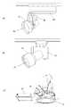
図28は本発明の高圧放電灯点灯装置を用いた照明器具の構成例を示す。(a)、(b)はそれぞれスポットライトにHIDランプを用いた例、(c)はダウンライトにHIDランプを用いた例であり、図中、DLは高圧放電灯、81は高圧放電灯を装着した灯体、82は配線、83は点灯装置の回路を格納した安定器である。(Embodiment 18)
FIG. 28 shows a structural example of a lighting fixture using the high pressure discharge lamp lighting device of the present invention. (A), (b) is an example using an HID lamp as a spotlight, and (c) is an example using an HID lamp as a downlight. In the figure, DL is a high pressure discharge lamp, 81 is a high pressure discharge lamp. A mounted lamp body, 82 is a wiring, and 83 is a ballast storing a circuit of a lighting device.
これらの点灯装置として前述の高圧放電灯点灯装置を用いることで始動時の非対称放電状態の継続を防いで、高圧放電灯を早く安定点灯状態へと移行させるため、始動失敗が少なく、始動性の良い照明器具を提供することができる。なお、これらの照明器具を複数組み合わせて照明システムを構築しても良い。 By using the above-described high-pressure discharge lamp lighting device as these lighting devices, the continuation of the asymmetric discharge state at the start is prevented, and the high-pressure discharge lamp is quickly shifted to the stable lighting state. A good lighting fixture can be provided. A lighting system may be constructed by combining a plurality of these lighting fixtures.
1 交流電源
2 直流電源回路
P 電力供給回路
5 始動回路
6 半波放電検出回路部
7 制御回路部
DL 高圧放電灯DESCRIPTION OF
Claims (28)
Translated fromJapanese前記半波放電検出回路は、高圧放電灯が絶縁破壊した後、その高圧放電灯の略定格ランプ電圧に達するまでの始動初期に、異なる極性の電圧差もしくは電流差の絶対値が、正常点灯時における矩形波交流出力の各半周期の電圧差もしくは電流差の最大ばらつき値よりも大きいことが検出された場合に半波放電現象であると判別し、
前記制御回路は、前記半波放電検出回路により半波放電現象であると判別されると、一定期間高圧放電灯を消灯させ、その後、再始動させる時に、前記直流電源回路または電力供給回路または始動回路のうち少なくとも1つの出力を調整することにより、負荷電圧の高い極性の矩形波半周期の電圧値もしくは電流値を負荷電圧の低い極性の矩形波半周期の電圧値もしくは電流値に近づける半波改善制御を実施することを特徴とする高圧放電灯点灯装置。At least a DC power supply circuit, a power supply circuit that converts power from the output from the DC power supply circuit and supplies it as a rectangular wave AC output to the high-pressure discharge lamp, a starting circuit that applies a high voltage for starting to the high-pressure discharge lamp, and these And a half-wave discharge detection circuit for detecting a half-wave discharge in which the load voltage or load current of one polarity and the other polarity of the rectangular-wave AC output is asymmetric. In the lighting device,
The half-wave discharge detection circuit has a voltage difference or current difference of different polarities at the time of normal lighting after the breakdown of the high-pressure discharge lamp until it reaches the approximate rated lamp voltage of the high-pressure discharge lamp. When it is detected that it is larger than the maximum variation value of the voltage difference or current difference of each half cycle of the rectangular wave AC output at, it is determined that it is a half-wave discharge phenomenon,
When the half-wave discharge detection circuit determines that the half-wave discharge phenomenon has occurred, the control circuit turns off the high-pressure discharge lamp for a certain period of time and then restarts the DC power supply circuit or power supply circuit or start-up. A half wave that adjusts the voltage value or current value of a rectangular wave half cycle with a high load voltage polarity to a voltage value or current value of a rectangular wave half cycle with a low load voltage by adjusting at least one output of the circuit. A high pressure discharge lamp lighting device characterized by performing improvement control.
Priority Applications (5)
| Application Number | Priority Date | Filing Date | Title |
|---|---|---|---|
| JP2008244950AJP2010080138A (en) | 2008-09-24 | 2008-09-24 | High-pressure discharge lamp lighting device, and lighting fixture |
| CA2679816ACA2679816C (en) | 2008-09-24 | 2009-09-22 | High pressure discharge lamp lighting device and luminaire using same |
| EP09012050.2AEP2170019A3 (en) | 2008-09-24 | 2009-09-22 | High pressure discharge lamp lighting device and luminaire using the same |
| US12/585,773US8115405B2 (en) | 2008-09-24 | 2009-09-24 | High pressure discharge lamp lighting device and luminaire using same |
| CN2009101786241ACN101686594B (en) | 2008-09-24 | 2009-09-24 | High pressure discharge lamp lighting device and luminaire using the same |
Applications Claiming Priority (1)
| Application Number | Priority Date | Filing Date | Title |
|---|---|---|---|
| JP2008244950AJP2010080138A (en) | 2008-09-24 | 2008-09-24 | High-pressure discharge lamp lighting device, and lighting fixture |
Publications (1)
| Publication Number | Publication Date |
|---|---|
| JP2010080138Atrue JP2010080138A (en) | 2010-04-08 |
Family
ID=42210352
Family Applications (1)
| Application Number | Title | Priority Date | Filing Date |
|---|---|---|---|
| JP2008244950APendingJP2010080138A (en) | 2008-09-24 | 2008-09-24 | High-pressure discharge lamp lighting device, and lighting fixture |
Country Status (1)
| Country | Link |
|---|---|
| JP (1) | JP2010080138A (en) |
Cited By (3)
| Publication number | Priority date | Publication date | Assignee | Title |
|---|---|---|---|---|
| JP2013247052A (en)* | 2012-05-29 | 2013-12-09 | Eye Lighting Syst Corp | Discharge lamp lighting device |
| JP2013251187A (en)* | 2012-06-01 | 2013-12-12 | Panasonic Corp | Discharge lamp lighting device, on-vehicle high-brightness discharge lamp lighting device using the same, on-vehicle head light device and vehicle |
| JP2014160586A (en)* | 2013-02-20 | 2014-09-04 | Seiko Epson Corp | Discharge lamp drive unit, projector and discharge lamp drive method |
Citations (4)
| Publication number | Priority date | Publication date | Assignee | Title |
|---|---|---|---|---|
| JPH0227695A (en)* | 1988-07-15 | 1990-01-30 | Matsushita Electric Works Ltd | Lighting device for discharge lamp |
| JPH11162666A (en)* | 1997-11-26 | 1999-06-18 | Mitsubishi Electric Corp | High pressure discharge lamp lighting device |
| JP2005158365A (en)* | 2003-11-21 | 2005-06-16 | Matsushita Electric Works Ltd | Discharge lamp lighting device and luminaire |
| JP2007207541A (en)* | 2006-02-01 | 2007-08-16 | Toshiba Lighting & Technology Corp | High pressure discharge lamp lighting device and lighting device |
- 2008
- 2008-09-24JPJP2008244950Apatent/JP2010080138A/enactivePending
Patent Citations (4)
| Publication number | Priority date | Publication date | Assignee | Title |
|---|---|---|---|---|
| JPH0227695A (en)* | 1988-07-15 | 1990-01-30 | Matsushita Electric Works Ltd | Lighting device for discharge lamp |
| JPH11162666A (en)* | 1997-11-26 | 1999-06-18 | Mitsubishi Electric Corp | High pressure discharge lamp lighting device |
| JP2005158365A (en)* | 2003-11-21 | 2005-06-16 | Matsushita Electric Works Ltd | Discharge lamp lighting device and luminaire |
| JP2007207541A (en)* | 2006-02-01 | 2007-08-16 | Toshiba Lighting & Technology Corp | High pressure discharge lamp lighting device and lighting device |
Cited By (3)
| Publication number | Priority date | Publication date | Assignee | Title |
|---|---|---|---|---|
| JP2013247052A (en)* | 2012-05-29 | 2013-12-09 | Eye Lighting Syst Corp | Discharge lamp lighting device |
| JP2013251187A (en)* | 2012-06-01 | 2013-12-12 | Panasonic Corp | Discharge lamp lighting device, on-vehicle high-brightness discharge lamp lighting device using the same, on-vehicle head light device and vehicle |
| JP2014160586A (en)* | 2013-02-20 | 2014-09-04 | Seiko Epson Corp | Discharge lamp drive unit, projector and discharge lamp drive method |
Similar Documents
| Publication | Publication Date | Title |
|---|---|---|
| JP5193445B2 (en) | High pressure discharge lamp lighting device and lighting fixture | |
| US8115405B2 (en) | High pressure discharge lamp lighting device and luminaire using same | |
| CN102047766B (en) | Discharge lamp lighting device | |
| JP2007115660A (en) | High pressure discharge lamp lighting device and lighting device | |
| WO2008001519A1 (en) | Electric discharge lamp device and lighting apparatus | |
| JP5379544B2 (en) | High pressure discharge lamp lighting device and lighting apparatus using the same | |
| US8593077B2 (en) | High-voltage discharge lamp lighting device and lighting fixture | |
| JP2001338789A (en) | Discharge lamp lighting device | |
| JP2010080138A (en) | High-pressure discharge lamp lighting device, and lighting fixture | |
| CN103379719A (en) | Discharge lamp lighting device, and illumination apparatus and vehicle including same | |
| JP2010080137A (en) | High pressure discharge lamp lighting device and luminaire | |
| JP5460065B2 (en) | Discharge lamp lighting circuit | |
| JP4752136B2 (en) | Discharge lamp lighting device | |
| JP2005038814A (en) | Discharge lamp lighting device, illumination device, and projector | |
| JP5348497B2 (en) | High pressure discharge lamp lighting device, projector, and high pressure discharge lamp starting method | |
| JP2010257659A (en) | High pressure discharge lamp lighting device and lighting apparatus using the same | |
| JP5870315B2 (en) | High pressure discharge lamp lighting device and lighting fixture | |
| JP5947587B2 (en) | Discharge lamp lighting device | |
| JP2010055915A (en) | High pressure discharge lamp lighting device, light source device, and starting method of high pressure discharge lamp | |
| JP2002352975A (en) | Lighting equipment for electric discharge lamp | |
| JP2002352972A (en) | Lighting equipment for electric discharge lamp | |
| JPWO2008123274A1 (en) | High-intensity discharge lamp lighting device | |
| JP2011009019A6 (en) | High pressure discharge lamp lighting device, lighting apparatus and lighting system using the same | |
| JP2011009019A (en) | High voltage discharge lamp lighting-up device, lighting fixture, and lighting system | |
| JP2002352987A (en) | Electric discharge lamp lighting equipment |
Legal Events
| Date | Code | Title | Description |
|---|---|---|---|
| A621 | Written request for application examination | Free format text:JAPANESE INTERMEDIATE CODE: A621 Effective date:20110920 | |
| A521 | Written amendment | Free format text:JAPANESE INTERMEDIATE CODE: A821 Effective date:20111207 | |
| RD02 | Notification of acceptance of power of attorney | Free format text:JAPANESE INTERMEDIATE CODE: A7422 Effective date:20111207 | |
| RD04 | Notification of resignation of power of attorney | Free format text:JAPANESE INTERMEDIATE CODE: A7424 Effective date:20111214 | |
| A711 | Notification of change in applicant | Free format text:JAPANESE INTERMEDIATE CODE: A712 Effective date:20120112 | |
| A977 | Report on retrieval | Free format text:JAPANESE INTERMEDIATE CODE: A971007 Effective date:20130208 | |
| A131 | Notification of reasons for refusal | Free format text:JAPANESE INTERMEDIATE CODE: A131 Effective date:20130319 | |
| A02 | Decision of refusal | Free format text:JAPANESE INTERMEDIATE CODE: A02 Effective date:20130709 |