JP2010069307A - Lockout arrangement for surgical stapler - Google Patents
Lockout arrangement for surgical staplerDownload PDFInfo
- Publication number
- JP2010069307A JP2010069307AJP2009216532AJP2009216532AJP2010069307AJP 2010069307 AJP2010069307 AJP 2010069307AJP 2009216532 AJP2009216532 AJP 2009216532AJP 2009216532 AJP2009216532 AJP 2009216532AJP 2010069307 AJP2010069307 AJP 2010069307A
- Authority
- JP
- Japan
- Prior art keywords
- actuator
- drive slot
- surgical stapler
- latch
- handle portion
- Prior art date
- Legal status (The legal status is an assumption and is not a legal conclusion. Google has not performed a legal analysis and makes no representation as to the accuracy of the status listed.)
- Granted
Links
- 238000005520cutting processMethods0.000claimsabstractdescription96
- 230000007246mechanismEffects0.000description55
- 238000010304firingMethods0.000description7
- 238000000034methodMethods0.000description7
- 239000012636effectorSubstances0.000description6
- 239000000463materialSubstances0.000description5
- 238000000465mouldingMethods0.000description5
- 238000001356surgical procedureMethods0.000description5
- 230000001174ascending effectEffects0.000description3
- 239000003795chemical substances by applicationSubstances0.000description3
- 238000004140cleaningMethods0.000description3
- 230000001681protective effectEffects0.000description3
- 230000003872anastomosisEffects0.000description2
- 230000000694effectsEffects0.000description2
- 230000002496gastric effectEffects0.000description2
- 238000003780insertionMethods0.000description2
- 230000037431insertionEffects0.000description2
- 239000003562lightweight materialSubstances0.000description2
- 238000000691measurement methodMethods0.000description2
- 210000000056organAnatomy0.000description2
- 230000005855radiationEffects0.000description2
- 238000000926separation methodMethods0.000description2
- 229910001220stainless steelInorganic materials0.000description2
- 239000010935stainless steelSubstances0.000description2
- 241000894006BacteriaSpecies0.000description1
- RTAQQCXQSZGOHL-UHFFFAOYSA-NTitaniumChemical compound[Ti]RTAQQCXQSZGOHL-UHFFFAOYSA-N0.000description1
- 239000004775TyvekSubstances0.000description1
- 229920000690TyvekPolymers0.000description1
- 230000006978adaptationEffects0.000description1
- 210000004204blood vesselAnatomy0.000description1
- 238000013461designMethods0.000description1
- 210000001198duodenumAnatomy0.000description1
- 238000005516engineering processMethods0.000description1
- 210000003238esophagusAnatomy0.000description1
- 210000001035gastrointestinal tractAnatomy0.000description1
- 230000006872improvementEffects0.000description1
- 238000002347injectionMethods0.000description1
- 239000007924injectionSubstances0.000description1
- 230000003993interactionEffects0.000description1
- 210000004072lungAnatomy0.000description1
- 230000014759maintenance of locationEffects0.000description1
- 238000004519manufacturing processMethods0.000description1
- 238000012986modificationMethods0.000description1
- 230000004048modificationEffects0.000description1
- 239000012858resilient materialSubstances0.000description1
- 230000001954sterilising effectEffects0.000description1
- 238000004659sterilization and disinfectionMethods0.000description1
- 210000002784stomachAnatomy0.000description1
- 229910052719titaniumInorganic materials0.000description1
- 239000010936titaniumSubstances0.000description1
Images


Landscapes
- Surgical Instruments (AREA)
Abstract
Description
Translated fromJapanese背景
〔i.技術分野〕
本発明は、ステープリング器具に関し、様々な実施形態においては、ステープルの1つ以上の列を作り出すための外科用ステープリング器具に関する。Background [i. Technical field〕
The present invention relates to stapling instruments and, in various embodiments, to surgical stapling instruments for creating one or more rows of staples.
〔ii.関連技術の背景〕
近年、外科医が、肺、食道、胃、十二指腸、および/または腸管における他の臓器など体組織を縫合するためにステープリング器具を使用する傾向が高まってきている。適切なステープリング器具の使用により、多くの場合、より短い時間でより良い仕事をすることができ、また、胃腸管吻合など以前は困難であった外科処置を単純化することができる。以前の、直線状の列が2つおよび4つの切断ステープラは、カートリッジのない器具が含まれ、その中にステープルが個々に手で装填されるものであった。他の以前の装置は、組織を分断しステープル列を形成することを同時に行なうために利用されることができた、前殺菌された使い捨てステープル装填ユニット、および切断部材を含んでいた。このような外科用ステープラの例は、1970年3月10日に発行された名称「INSTRUMENT FOR PLACING LATERAL GASTROINTESTINAL ANASTOMOSES」の米国特許第3,499,591号に開示されている。これにより、この特許の開示内容全体が参照によって本明細書に組み込まれたものとする。[Ii. Related Technology Background)
In recent years, there has been an increasing tendency for surgeons to use stapling instruments to suture body tissues such as the lungs, esophagus, stomach, duodenum, and / or other organs in the intestinal tract. The use of appropriate stapling instruments can often do a better job in a shorter amount of time and can simplify previously difficult surgical procedures such as gastrointestinal anastomosis. Previously, the two linear rows and four cutting staplers included instruments without cartridges into which the staples were individually loaded manually. Other previous devices included pre-sterilized disposable staple loading units and cutting members that could be used to simultaneously sever tissue and form staple rows. An example of such a surgical stapler is disclosed in US Pat. No. 3,499,591, issued March 10, 1970, under the name “INSTRUMENT FOR PLACING LATERAL GASTROINTESTINAL ANASTOMOSES”. The entire disclosure of this patent is hereby incorporated herein by reference.
ステープリング器具は、一対の協働する細長い顎部材を含むことができ、各顎部材は、吻合されるべき体内管状臓器に挿入されるように構成されうる。様々な実施形態では、顎部材の一方は、少なくとも2つの側方向に離隔されたステープル列を備えたステープルカートリッジを支持することができ、他方の顎部材は、ステープルカートリッジ内のステープル列と整列されたステープル成形ポケットを備えたアンビルを支持することができる。一般的に、ステープリング器具は、プッシュバーおよびナイフブレードをさらに含むことができ、プッシュバーおよびナイフブレードは、プッシュバー上のカム面によりステープルカートリッジからステープルを連続的に排出するために顎部材に対してスライド可能である。少なくとも1つの実施形態では、カートリッジにより保持されて個々のステープルと関連する複数のステープルドライバを作動させて、ステープルをアンビルに対して押し付けて、顎部材の間に把持された組織に変形されたステープルの側方向に離隔された列を形成するように、カム面は構成されうる。しかしながら、典型的なステープリング器具では、アンビルは、いったん顎部材が共に組み立てられると、ステープルカートリッジに対して動くことができず、成形されるステープルの高さは、調節されることができない。少なくとも1つの実施形態では、ナイフブレードは、プッシュバーの後を追い、ステープル列の間のラインに沿って組織を切断することができる。このようなステープリング器具の例は、1984年2月7日に発行された名称「SURGICAL INSTRUMENTS」の米国特許第4,429,695号に開示されている。これにより、この特許の開示内容全体が参照によって本明細書に組み込まれたものとする。 The stapling instrument can include a pair of cooperating elongate jaw members, each jaw member being configured to be inserted into a body tubular organ to be anastomosed. In various embodiments, one of the jaw members can support a staple cartridge with at least two laterally spaced staple rows and the other jaw member is aligned with the staple rows in the staple cartridge. An anvil with a staple forming pocket can be supported. Generally, the stapling instrument can further include a push bar and a knife blade that pushes the jaw members to continuously eject the staples from the staple cartridge by a cam surface on the push bar. On the other hand, it can slide. In at least one embodiment, the staples held by the cartridge and actuating a plurality of staple drivers associated with the individual staples to press the staples against the anvil and deformed into tissue grasped between the jaw members. The cam surface may be configured to form a laterally spaced row. However, in a typical stapling instrument, the anvil cannot move relative to the staple cartridge once the jaw members are assembled together, and the height of the formed staple cannot be adjusted. In at least one embodiment, the knife blade can follow the push bar and cut tissue along the line between the staple rows. An example of such a stapling instrument is disclosed in US Pat. No. 4,429,695 issued February 7, 1984 under the name “SURGICAL INSTRUMENTS”. The entire disclosure of this patent is hereby incorporated herein by reference.
様々な実施形態では、典型的なステープリング器具は、ラッチにより共に固定されうる第1および第2顎部材を含むことができ、ラッチは、開放位置と、部分的閉鎖された位置と、閉鎖された位置との間で動かされうる。しかしながら、ラッチの開放位置および部分的に閉鎖された位置では、典型的なステープリング器具の第1および第2顎部材は、故意的でなく互いから分離され、それゆえに顎部材を再組立するため追加の時間を必要とする場合がある。ある状況では、第1および第2顎部材の分離は、ナイフブレードを露出する場合もある。様々な状況では、前述に加えて、ステープリング器具は、プッシュバーから延びるアクチュエータノブを含むことができ、このアクチュエータノブは、外科医によって把持され、かつ、ステープルカートリッジ内部でプッシュバーおよびナイフブレードを前進させるために遠位に前進させられるように構成されうる。しかしながら、ある状況では、アクチュエータノブは、第1および第2顎部材が組み立てられていなくても、顎部材に対して前進させられうる。いったん組み立てられると、少なくとも1つの状況では、アクチュエータノブが外科用器具から外側に延びることができるとき、アクチュエータノブは、故意的でなく手術部位を取り囲む組織に接触する場合があり、結果として、組織がアクチュエータノブの前進を妨げることもありうる。そのような状況では、外科医は、組織を通り過ぎるようアクチュエータノブを押し進めること、および/または、ステープリング器具を再位置付けることを必要とする場合もあり、そのことは手術を完了するのに必要とされる時間を増加させることがある。必要とされているものは、上述を超える改良である。 In various embodiments, an exemplary stapling instrument can include first and second jaw members that can be secured together by a latch, the latch being closed in an open position and a partially closed position. Can be moved between different positions. However, in the open and partially closed position of the latch, the first and second jaw members of a typical stapling instrument are unintentionally separated from each other, and therefore to reassemble the jaw members May require additional time. In certain situations, separation of the first and second jaw members may expose the knife blade. In various situations, in addition to the foregoing, the stapling instrument can include an actuator knob that extends from the push bar, which is gripped by the surgeon and advances the push bar and knife blade within the staple cartridge. Can be configured to be advanced distally for However, in certain situations, the actuator knob can be advanced relative to the jaw members even though the first and second jaw members are not assembled. Once assembled, in at least one situation, when the actuator knob can extend outward from the surgical instrument, the actuator knob may unintentionally contact the tissue surrounding the surgical site, resulting in tissue May prevent the actuator knob from moving forward. In such situations, the surgeon may need to push the actuator knob past the tissue and / or reposition the stapling instrument, which is required to complete the surgery. May increase the time required. What is needed is an improvement over the above.
〔概要〕
本発明の少なくとも1つの形態では、外科用ステープリング器具は、互いに旋回可能に接続され、かつラッチにより互いに対して適所に固定されることができる、第1および第2顎部材を含むことができる。様々な実施形態では、第1および第2顎部材は、第1および第2顎部材が互いに対して回転させられることができるが、第1および第2顎部材が互いから引き離されることを防ぐか、あるいは少なくとも抑制することができる、第1および第2ロック部材を含むことができる。そのような実施形態は、ラッチが部分的に閉鎖された位置にある状況、ならびに、第1および第2顎部材がそれら間に組織を位置付けるように操作されている状況で、特に有用でありうる。少なくとも1つのそのような実施形態では、第1および第2顎部材が互いから分離させられて切断部材を露出する可能性を防ぐか、あるいは少なくともその可能性を減ずるために、第1および第2顎部材は、共に十分に接続されることができる。本発明の少なくとも1つの形態では、外科用ステープリング器具は、切断部材上および/または切断部材周りに少なくとも部分的に延びることができるハウジングを含むことができる。様々な実施形態では、ハウジングは、第1および第2顎部材が互いから分離された場合に切断部材を少なくとも部分的に覆い、そのうえ、使用の間、切断部材が第1および第2顎部材に対して動かされることを可能にすることができる。〔Overview〕
In at least one form of the invention, the surgical stapling instrument can include first and second jaw members that are pivotally connected to each other and can be secured in place by a latch. . In various embodiments, the first and second jaw members may allow the first and second jaw members to be rotated relative to each other but prevent the first and second jaw members from being pulled away from each other. Alternatively, it can include first and second locking members that can be at least restrained. Such an embodiment may be particularly useful in situations where the latch is in a partially closed position and where the first and second jaw members are manipulated to position tissue therebetween. . In at least one such embodiment, the first and second jaw members are separated from each other to prevent or at least reduce the possibility of exposing the cutting member. The jaw members can be fully connected together. In at least one form of the invention, a surgical stapling instrument can include a housing that can extend at least partially over and / or around the cutting member. In various embodiments, the housing at least partially covers the cutting member when the first and second jaw members are separated from each other, and further, the cutting member is in contact with the first and second jaw members during use. It can be allowed to be moved against.
様々な実施形態では、外科用ステープリング器具は、第1および第2顎部材に対して前進および/または後退させられうる、切断部材および/またはステープルスレッドをさらに含むことができる。ある実施形態では、ステープルスレッドは、第1および第2顎部材の一方の中のステープルカートリッジからステープルを配備するために、切断部材によって、および/または切断部材と共に、前進させられうる。本発明の少なくとも1つの形態では、外科用ステープリング器具は、ロックを含むことができ、このロックは、ラッチが閉鎖される前、第1および第2顎部材に対して切断部材および/またはステープルスレッドが動かされること、または少なくとも前進させられることを、防ぐか、または少なくとも抑制することができる。少なくとも1つの実施形態では、ラッチは、ラッチが完全な開放位置から完全に閉鎖された位置に動かされるとロックに係合するように、また、切断部材および/またはステープルスレッドからロックを作用可能に係合解除するように、構成されうる。少なくとも1つの実施形態では、第1および第2顎部材の一方は、ステープルがステープルカートリッジから配備されるとステープルを変形させるように構成されうる少なくとも1つの成形面を有するアンビルを含むことができる。本発明の少なくとも1つの形態では、アンビルは、ステープルが変形させられる量を調節するために、ステープルカートリッジに対して可動式に調節可能でありうる。様々な実施形態では、アンビルは、スライド可能な調節用プレートおよび/または回転可能カムによって調節されうる。 In various embodiments, the surgical stapling instrument can further include a cutting member and / or a staple thread that can be advanced and / or retracted relative to the first and second jaw members. In certain embodiments, staple threads can be advanced by and / or with a cutting member to deploy staples from a staple cartridge in one of the first and second jaw members. In at least one form of the invention, the surgical stapling instrument can include a lock that is a cutting member and / or staple relative to the first and second jaw members before the latch is closed. The sled can be prevented or at least inhibited from being moved or at least advanced. In at least one embodiment, the latch engages the lock when the latch is moved from the fully open position to the fully closed position, and allows the lock to act from the cutting member and / or staple sled. It can be configured to disengage. In at least one embodiment, one of the first and second jaw members can include an anvil having at least one molding surface that can be configured to deform the staple when the staple is deployed from the staple cartridge. In at least one form of the invention, the anvil can be movably adjustable relative to the staple cartridge to adjust the amount by which the staple is deformed. In various embodiments, the anvil can be adjusted by a slidable adjustment plate and / or a rotatable cam.
添付の図面と共に本発明の実施形態の以下の説明を参照することにより、本発明の前述されたおよび他の特徴および利点、ならびにそれらを達成する方法が、より明らかになるであろうし、本発明自体がより深く理解されるであろう。 The foregoing and other features and advantages of the present invention, as well as the manner of achieving them, will become more apparent from the following description of embodiments of the present invention, taken in conjunction with the accompanying drawings, in which: It will be understood more deeply.
対応する参照符号は、いくつかの図面にわたって対応する部分を示している。本明細書に述べられる例証は、一形態において本発明の好ましい実施形態を図示し、そのような例証は、本発明の範囲をいかようにも限定するものとして解釈されるものではない。 Corresponding reference characters indicate corresponding parts throughout the several views. The illustrations set forth herein illustrate, in one form, preferred embodiments of the invention and are not to be construed as limiting the scope of the invention in any way.
〔詳細な説明〕
ここで、ある例示的実施形態が、本明細書に開示される装置および方法の構造、機能、製造および使用の原理の全般的な理解を提供するために記載される。これら実施形態の1つ以上の例は、添付の図面において図示されている。当業者であれば、特に本明細書に特に記載され添付の図面に図示されている装置および方法は、非限定的な例示的実施形態であり、本発明の様々な実施形態の範囲は、特許請求の範囲によってのみ定められることを理解するであろう。一例示的実施形態に関連して図示され、あるいは説明された特徴は、他の実施形態の特徴と組み合わされてもよい。そのような修正および変形は、本発明の範囲内に含まれると意図される。[Detailed explanation]
Certain exemplary embodiments will now be described to provide a general understanding of the principles of structure, function, manufacture and use of the devices and methods disclosed herein. One or more examples of these embodiments are illustrated in the accompanying drawings. For those skilled in the art, the devices and methods specifically described herein and illustrated in the accompanying drawings are non-limiting exemplary embodiments, and the scope of the various embodiments of the present invention is subject to patents. It will be understood that this is only defined by the claims. The features illustrated or described in connection with one exemplary embodiment may be combined with the features of other embodiments. Such modifications and variations are intended to be included within the scope of the present invention.
共同所有される3つの米国非仮特許出願が、本願と同時に出願された。出願時、これら3つの出願は:
SURGICAL STAPLING INSTRUMENT WITH CUTTING MEMBER ARRANGEMENT、代理人整理番号END6414USNP/080203、発明者:Chester BaxterおよびJames Bedi;
SURGICAL STAPLER HAVING AN INTERMEDIATE CLOSING POSITION、代理人整理番号END6411USNP/080200、発明者:Chester BaxterおよびJames Bedi;ならびに、
SURGICAL STAPLER WITH APPARATUS FOR ADJUSTING STAPLE HEIGHT、代理人整理番号END6406USNP/080195、発明者:Chester BaxterおよびJames Bedi、として識別可能であった。これにより、これら特許出願の開示内容全体が参照によって本明細書に組み込まれたものとする。Three co-owned US non-provisional patent applications were filed concurrently with this application. At the time of filing, these three applications are:
SURGICAL STAPLING INSTRUMENT WITH CUTTING MEMBER ARRANGEMENT, agent reference number END6414USNP / 080203, inventors: Chester Baxter and James Bedi;
SURGICAL STAPLER HAVING AN INTERMEDIATE CLOSING POSITION, agent reference number END6411USNP / 080200, inventors: Chester Baxter and James Bedi;
It was identifiable as SURGICAL STAPLER WITH APPARATUS FOR ADJUSTING STAPLE HEIGHT, agent reference number END6406USNP / 080195, inventors: Chester Baxter and James Bedi. The entire disclosure of these patent applications is hereby incorporated herein by reference.
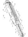
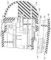
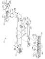
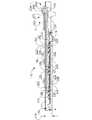
図1を参照すると、全体が100として示される、外科用ステープリング器具は、第1ハンドル部分102と、第2ハンドル部分104と、を含むことができる。様々な実施形態では、第1ハンドル部分102および第2ハンドル部分104は、外科医によって把持されるように構成され得、例えば、ハンドルグリップ部分106を含み得る。少なくとも1つの実施形態では、図2および図3を参照すると、第1ハンドル部分102は、第1フレーム110に取り付けられた第1カバー108を含むことができ、同様に、第2ハンドル部分104は、第2フレーム114に取り付けられた第2カバー112を含むことができる。カバー108および112は、外科医が手術部位の内部でステープル器具100を操作するのを助けるように、人間工学的に輪郭付けられ、あるいは別様に適切に輪郭付けられ得る。様々な実施形態では、ハンドルカバー108および112は、例えば、それぞれ拡大された突出部109および113を含むことができ、拡大された突出部109および113は、ステープリング器具100の手術部位への挿入を容易にすることができる。様々な実施形態では、ハンドルカバー108および112は、例えば、プラスチック、軽量材料、および/または任意の他の適切な材料から作られ得る一方で、ハンドルフレーム110および114は、例えば、ステンレス鋼、チタン、および/または任意の他の適切な材料から作られ得る。 With reference to FIG. 1, a surgical stapling instrument, generally indicated as 100, can include a
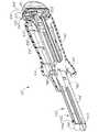
様々な実施形態では、図1〜図3を再び参照すると、ハンドル部分102および104の遠位端は、例えば、手術部位の内部で組織を治療するように構成され得るエンドエフェクタ120を含むことができる。少なくとも1つのそのような実施形態では、エンドエフェクタ120は、以下でさらなる詳細が説明されるように、ステープルカートリッジを受容および/または確保するように構成されたステープルカートリッジチャネル122を含むことができる。ある実施形態では、ステープルカートリッジチャネル122は、第1ハンドル部分フレーム110から延びる一部品である細長いチャネル形状フレームを含むことができる。少なくとも1つ実施形態では、ステープルカートリッジチャネル122は、底壁126によって接続された、一対の対向する細長い側壁124を含むことができる。ステープルカートリッジチャネル122の後方すなわち近位の部分に沿って、一対の離隔された直立側方フランジ128が、対向する側壁124から上方に延びることができる。様々な実施形態では、側方フランジ128の間のステープルカートリッジチャネル122の幅は、第2ハンドル部分104から延びる上顎部材すなわちアンビル130の幅よりも広くすることができる。少なくとも1つの実施形態では、フランジ128の間の距離は、ステープリング器具が手術のために組み立てられるとき、アンビル130の少なくとも一部分が側方フランジ128の間に受容されることが可能となるように構成され得る。図2に示すように、各側方フランジ128は、例えば、ノッチすなわち凹部127を含むことができ、このノッチすなわち凹部127は、以下でさらなる詳細が説明されるように、例えば、アンビル130から延びる1つ以上のラッチ突出部131を、および/または、第2ハンドル部分104の任意の他の適切な部分を受容するように構成され得る。 In various embodiments, referring again to FIGS. 1-3, the distal ends of the
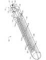
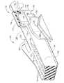
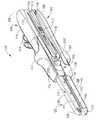
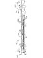
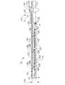
上記で示されたように、図1〜図3を再度参照すると、ステープルカートリッジチャネル122は、例えばステープルカートリッジ150などのステープルカートリッジを、エンドエフェクタ120内部で支持および/または確保するように構成され得、ステープルカートリッジは、その中に取り外し可能に収容された(不図示の)1つ以上のステープルを含むことができる。様々な実施形態では、図8〜図10を参照すると、ステープルカートリッジ150は、例えば側方に離隔された少なくとも2つの長さ方向列など任意の適切な配列で、ステープルを収容するように構成され得る1つ以上のステープルキャビティ151を含むことができる。少なくとも1つの実施形態では、図9および図10を参照すると、ステープルカートリッジ150は、ステープルカートリッジ本体152および皿部154を含むことができ、ステープルカートリッジ本体152および/または皿部154は、ステープルスレッドおよび/または切断部材をスライド可能に受容するための、チャネルまたは通路を画定するように構成され得る。少なくとも1つの実施形態では、皿部154は、例えば、可撓性アーム155を含むことができ、この可撓性アーム155は、ステープルカートリッジ本体152にスナップ嵌め式および/またはプレス嵌め式に係合するように構成され得る。図10〜図12を参照すると、ステープルカートリッジ150は、ステープルスレッド部分162、加えて切断部材164を含むことができる、ステープルスレッド組立体160をさらに含むことができる。様々な実施形態では、切断部材164は、例えば、切断エッジ165およびロックアーム166を含むことができ、ロックアーム166は、切断部材164がステープルスレッド部分162に組み合わせられるとき、ステープルスレッド162内の開口部163の中に、プレス嵌めおよび/またはスナップ嵌めされるように構成され得る。他の様々な実施形態では、ステープルスレッド部分162は、切断部材164に一体的に成型され得る。 As indicated above, referring again to FIGS. 1-3,
前述に加えて、図8〜図10を参照すると、ステープルカートリッジ本体152は、例えばスロット156などのスロットを含むことができ、スロットは、その内部に切断部材164の少なくとも一部分を、ならびに/または、ステープルスレッド組立体160および(以下で論じられる)プッシュバー組立体200の任意の他の部分を受容するように構成され得、スロット156は、切断部材164がステープルカートリッジ150内部で第1および第2位置の間を動かされることを可能にするように構成されうる。様々な実施形態では、スロット156は、例えば、ステープルカートリッジ150とアンビル130との中間に位置付けられた組織を切開するために、切断部材164が近位位置(図10)と遠位位置との間で動かされることを可能にするように構成されうる。図10〜図12を再度参照すると、ステープルスレッド部分162は、ステープルカートリッジ150内部に位置付けられたステープルドライバに係合するように構成され得る、カム面、斜面またはアクチュエータ面167を含むことができる。様々な実施形態では、図9を参照すると、ステープルカートリッジ150は、スレッド部分162によってステープルキャビティ151内部で上方に持ち上げられ得る、すなわちスライドさせられ得る、ステープルドライバ168を含むことができ、それゆえ、ステープルドライバ168の上方移動が、ステープルキャビティ151内部に少なくとも部分的に位置付けられたステープルを排出または配備できるようになっている。ステープルドライバ168は実際に垂直方向上方に持ち上げられることができるが、上方等の用語は、例えばステープルドライバ168が、例えば、ステープルカートリッジの上面すなわちデッキ158に向かって、および/または、アンビル130に向かって、動かされることを意味することができる。ある実施形態では、図9に図示されているように、各ステープルドライバ168は、カム面167と同じ角度に、および/または任意の他の適切な角度に、方向付けられた1つ以上の傾斜面169を含むことができ、この傾斜面169は、ステープルスレッド162とステープルドライバ168との間に、比較的平坦な、または少なくとも実質的に平坦な、スライド用接触面を提供することができる。様々な実施形態では、ステープルドライバは、1つのみのステープルを配備するように構成されうるが、ある実施形態では、ステープルドライバは、例えば、隣接する列に位置する2つ以上のステープルを同時に配備するように構成され得る。他の装置が、2008年2月13日に出願された、名称「SURGICAL STAPLING INSTRUMENT WITH IMPROVED FIRING TRIGGER ARRANGEMENT」である、米国特許出願第12/030,424号に開示されている。これにより、この特許出願の開示内容全体が参照によって本明細書に組み込まれたものとする。 In addition to the foregoing, referring to FIGS. 8-10, the
様々な実施形態では、前述されたように、外科用ステープリング器具は、組織を切開し、ステープルカートリッジからステープルを配備するように構成された切断部材/ステープルスレッド組立体を含むことができる。しかし、ある実施形態では、外科用ステープリング器具は、切断部材を必要としない、すなわち含まない場合もある。少なくとも1つのそのような実施形態では、ステープルカートリッジは、その中に位置付けられたステープルスレッドを含むことができ、および/または、外科用器具は、例えば、組織を別様に切断することなく組織をステープリングするために、ステープルスレッドをステープルカートリッジの中へ動かすように構成され得る。ある他の実施形態では、ステープルカートリッジは、その内部に位置付けられたステープルスレッドを含むことができ、外科用器具は、ステープルカートリッジ内へ可動な、またはステープルカートリッジに対して可動な、切断部材を含むことができる。少なくとも1つのそのような実施形態では、切断部材は、ステープルスレッドと接触するように前進されられて、切断部材およびステープルスレッドが共に前進させられ得るようになっている。その後、切断部材は、ステープルカートリッジが外科用器具から分離されて、新しいステープルスレッドを有する新しいステープルカートリッジで置換されることができるように、十分に後退させられ得る。そのような実施形態は、ステープルスレッドが、使用の間に、摩滅または変形した場合に有用となりうる。ステープルカートリッジがその内部に位置付けられた切断部材を含むことができ、外科用器具がステープルカートリッジの中に可動な、またはステープルカートリッジに対して可動なステープルスレッドを含むことができる、他の実施形態が想到される。少なくとも1つのそのような実施形態では、前述と同様に、ステープルスレッドは、前進させられて切断部材と接触することができ、それにより切断部材およびステープルスレッドが共に前進させられうるようになっている。その後、ステープルスレッドは、ステープルカートリッジが外科用器具から分離させられて新しい切断部材を有する新しいステープルカートリッジで置換されることが可能なように、十分に後退させられ得る。そのような実施形態は、切断部材が、使用の間に、摩滅または変形した場合に有用となりうる。様々な実施形態では、以下でさらなる詳細が説明されるように、ステープルカートリッジは、例えば、外科医または他の臨床医が、ステープルカートリッジを取り扱う間、ステープルカートリッジ内部に位置付けられた切断部材に触れる可能性を妨げる、または少なくともその可能性を減ずるように構成された、保護ハウジングまたはカバーを含むことができる。 In various embodiments, as previously described, a surgical stapling instrument can include a cutting member / staple sled assembly configured to incise tissue and deploy staples from a staple cartridge. However, in certain embodiments, the surgical stapling instrument may not require or include a cutting member. In at least one such embodiment, the staple cartridge can include a staple thread positioned therein and / or the surgical instrument can remove tissue without, for example, cutting tissue differently. It may be configured to move the staple sled into the staple cartridge for stapling. In certain other embodiments, the staple cartridge can include a staple sled positioned therein, and the surgical instrument includes a cutting member that is movable into or movable relative to the staple cartridge. be able to. In at least one such embodiment, the cutting member is advanced into contact with the staple sled so that the cutting member and staple sled can be advanced together. The cutting member can then be fully retracted so that the staple cartridge can be separated from the surgical instrument and replaced with a new staple cartridge having a new staple thread. Such an embodiment may be useful if the staple thread is worn or deformed during use. Other embodiments in which the staple cartridge can include a cutting member positioned therein and the surgical instrument can include a staple sled that is movable within or relative to the staple cartridge. It is conceived. In at least one such embodiment, as before, the staple sled can be advanced into contact with the cutting member such that the cutting member and staple sled can be advanced together. . The staple sled can then be fully retracted so that the staple cartridge can be separated from the surgical instrument and replaced with a new staple cartridge having a new cutting member. Such an embodiment may be useful if the cutting member is worn or deformed during use. In various embodiments, as will be described in further detail below, the staple cartridge may contact a cutting member positioned within the staple cartridge, for example, while a surgeon or other clinician handles the staple cartridge. Can include a protective housing or cover configured to prevent or at least reduce the likelihood of this.
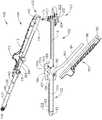
様々な実施形態では、前述に加えて、例えばステープルカートリッジチャネル122および/またはステープルカートリッジ150は、ステープルカートリッジチャネル122内部にステープルカートリッジ150を取り外し可能に確保するように構成され得る、例えば1つ以上の協働する突出部および/または凹部を含むことができる。いったんステープルカートリッジ150がステープルカートリッジチャネル122に挿入されたら、様々な実施形態では、第1ハンドル部分102は、第2ハンドル部分104に組み合わせられ得る。他の様々な実施形態では、ステープルカートリッジは、第1および第2ハンドル部分が共に組み合わされた後、ステープルカートリッジチャネルに挿入されてよい。いずれに場合でも、図1〜図7を参照すると、第1ハンドル部分102および第2ハンドル部分104は、それぞれ近位端103および105を含むことができ、近位端103および105は、第1および第2ハンドル部分が互いに回転可能または旋回可能に連結されうるように、共に組み合わせられ得る。様々な実施形態では、図2および図3を参照すると、第1ハンドル部分102は、そこから延びる1つ以上のピンまたは突出部111を含むことができ、このピンまたは突出部111は、第2ハンドル部分104内の1つ以上の溝、チャネル、またはスロット115の内部にスライド可能に受容されるように構成されうる。ある実施形態では、例えば、スロット115は、第2ハンドルフレーム114内に画定され得、突出部111は、第1ハンドルフレーム110から延びる近位端支柱107から延びることができる。第1ハンドル部分102および第2ハンドル部分104を組み合わせるために、図4を参照すると、スロット115の開口端が突出部111と整列させられ得、それにより例えば第2ハンドル部分104は第1ハンドル部分102に対して並進運動することができ、突出部111は、スロット115内部でスライドさせられ得るようになっている。少なくとも1つの実施形態では、図2および図3に図示されているように、スロット115の開口端は、スロットの閉鎖端に対して近位に位置され得る。少なくとも1つのそのような実施形態では、第2ハンドル部分104の近位端105は、第1ハンドル部分102の近位端103に対して遠位に位置付けられ得、それにより第2ハンドル部分104は、スロット115内部に突出部111を位置付けるために近位に動かされ得るようになっている。様々な他の状況では、第1ハンドル部分102は、第2ハンドル部分104に対して近位に位置付けられ得、スロット115内部に突出部111を位置付けるために遠位にスライドさせられ得る。 In various embodiments, in addition to the foregoing, for example, the
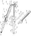
様々な実施形態では、図5を参照すると、第2ハンドル部分104は、第1ハンドル部分102に向かって回転させられ得、それによりアンビル130が、ステープルカートリッジ150および/またはステープルカートリッジチャネル122に対して適所に動かされ得るようになっている。ある実施形態では、第1ハンドル部分102は、第2ハンドル部分104に向かって回転させられ得、および/または、第1および第2ハンドル部分は、互いに向かって回転させられ得る。いずれの場合でも、突出部111およびスロット115は、互いに係合されると、旋回軸を含むことができ、この旋回軸周りに、第1および第2ハンドル部分の一方または両方が、互いに対して動かされ得る。様々な実施形態では、第2ハンドル部分104は、アンビル130がステープルカートリッジ150に接近した対向位置に動かされるように、第1ハンドル部分102に対して動かされ得る。ある実施形態では、図6を参照すると、第2ハンドル部分104は、第2ハンドル部分104から延びるラッチ突出部131が、第1ハンドル部分102内部の凹部127と整列させられ得る、および/または、凹部127に挿入され得るように、第1ハンドル部分102に対して動かされ得る。様々な実施形態では、主に図2および図3を参照すると、第1ハンドル部分102は、その第1ハンドル部分102に回転可能に据え付けられたラッチ機構180をさらに含むことができ、このラッチ機構180は、第2ハンドル部分104から延びるラッチ突出部131に係合して第1および第2ハンドル部分を共に確保するために利用され得る。図示はされていないが、ラッチ機構が第2ハンドル部分に回転可能に据え付けられ、ラッチ突出部が第1ハンドル部分から延びることができる、他の実施形態が想到される。いずれの場合でも、少なくとも1つの実施形態では、ラッチ機構180は、軸であって、ラッチ機構180がその軸周りに回転させられ得る、軸を定めるように構成され得る1つ以上の旋回軸ピン182によって第1フレーム110に据え付けられ得る。 In various embodiments, referring to FIG. 5, the
ある実施形態では、ここで図4および図5を参照すると、ラッチ機構180は、ラッチフレーム184、それに加えてラッチフレーム184に組み合わせられるラッチカバー186を含むことができる。他の様々な実施形態では、ラッチカバーおよびラッチフレームは、一体ユニットを含むことができ、あるいは、ある実施形態では、ラッチ機構は、カバーを含まないことさえある。ある実施形態では、ラッチフレーム184は、チャネル形状であり得、第1フレーム部分110にまたがる(span)のに十分な距離だけ離隔されている一対の対向する細長い側壁185を含むことができる。少なくとも1つの実施形態では、ラッチカバー186は、例えばプラスチック、軽量材料、および/または任意の他の適切な材料から作られ得るが、一方、ラッチフレーム184は、例えばステンレス鋼および/または任意の他の適切な材料から作られ得る。ある実施形態では、ラッチ機構180は、図7に図示されているように、閉鎖されると、ラッチカバー186は、第1ハンドルカバー108と整列させられ得る。ラッチカバー186は、外科医が外科用器具100を操作するのを助けるよう構成され得る輪郭付けられた部分187を含むことができ、少なくとも1つの実施形態では、輪郭付けられた部分187は、第1ハンドルカバー108から延びる突出部109と整列させられ得るか、または突出部109と少なくとも実質的に整列させられ得る。ラッチ機構180は、そのラッチ機構から延びる1つ以上のラッチアーム188をさらに含むことができ、このラッチアーム188は、図7に図示されているように、第2ハンドル部分104から延びる1つ以上のラッチ突出部131に係合するよう、また、凹部127内部に突出部131を引くおよび/または確保するよう、構成され得る。少なくとも1つの実施形態では、ラッチアーム188の少なくとも1つは、ラッチフレーム184と一体的に形成され得る。ある実施形態では、図6を参照すると、ラッチアーム188の少なくとも1つは、突出部131を包囲すなわち取り囲む、あるいは突出部131を少なくとも部分的に包囲すなわち取り囲むように、突出部131の少なくとも一部分の周りに巻き付くように構成され得る遠位フック189を含むことができる。少なくとも1つの実施形態では、ラッチアーム188は、ラッチ機構180をラッチ掛けされた(latched)すなわち閉鎖された位置に維持するためにオーバーセンターラッチ(over-center latch)として作用することができる。 In certain embodiments, referring now to FIGS. 4 and 5, the
使用の際、様々な状況では、第1ハンドル部分102および第2ハンドル部分104の一方は、手術部位内部の組織の第1側に位置付けられ得、他方のハンドル部分は、組織の反対側の適所へ回転させられ得る。そのような実施形態では、ステープルカートリッジ150は、組織の片側に位置付けられ得、アンビル130は、組織の反対側に位置付けられ得る。その後、上記でも概説されたように、第2ハンドル部分104を第1ハンドル部分102にラッチ掛けし、ステープルカートリッジ150とアンビル130との間に位置付けられた組織にクランプ力をかけるために、ラッチ機構180が開放位置と閉鎖された位置との間で動かされ得るように、ラッチ機構180は作動させられ得る。ある状況では、ラッチ機構180は、開放位置(図5)と、部分的に閉鎖された、すなわち中間位置(図6)と、閉鎖された位置(図7)との間で動かされ得る。少なくとも1つのそのような実施形態では、図5および図6を参照すると、ラッチ機構180は、ラッチアーム188が突出部131と係合させられていない開放位置と、ラッチアーム188が突出部131と係合させられた部分的に閉鎖された位置との間で動かされ得る。この部分的に閉鎖された位置では、例えば、アンビル130がステープルカートリッジ150に対して少なくとも部分的に対向させられてはいるが、エンドエフェクタ120が組織に対して再位置付けさせられることを可能にすることができる、十分なギャップが、アンビル130とステープルカートリッジ150との間に残ることができる。いったんアンビル130およびステープルカートリッジ150が組織に対して十分に位置付けられたら、ラッチ機構180は、部分的に閉鎖された位置と、図7に図示されているような閉鎖された位置との間で動かされ得る。 In use, in various situations, one of the
様々な実施形態では、前述に加えて、外科用ステープリング器具は、ステープリング器具の第1ハンドル部分を第2ハンドル部分から離れるように付勢するように構成され得る付勢部材をさらに含むことができる。少なくとも1つの実施形態では、以下でさらなる詳細が説明されるように、バネおよび/または任意の適切な弾力材料が、ステープリング器具のアンビルおよびステープルカートリッジが互いから離れるように付勢され得るように、第1ハンドル部分と第2ハンドル部分との中間に位置付けられ得る。ある実施形態では、バネは、アンビルとステープルカートリッジとの間にギャップが存在するように、第1および第2ハンドル部分を少なくとも部分的に引き離すように構成され得る。このギャップは、組織がアンビルとステープルカートリッジとの間に位置付けられることを可能にするのに十分なものとすることができる。使用の際、外科医は、そのような外科用ステープリング器具を、第1および第2ハンドル部分を互いから引き離して保持する必要なく、位置付けることができる。そのような器具は、ステープリング器具が部分的に閉鎖された構成にあり、外科医が手術部位内部でその器具を操作している場合に、特に有用であり得る。外科医がステープリング器具の位置付けに満足した後、外科医は、バネを圧縮および/または係合解除して、ステープリング器具を閉鎖された構成に置くことができる。 In various embodiments, in addition to the foregoing, the surgical stapling instrument further includes a biasing member that can be configured to bias the first handle portion of the stapling instrument away from the second handle portion. Can do. In at least one embodiment, as described in further detail below, the spring and / or any suitable resilient material can be biased so that the anvil and staple cartridge of the stapling instrument move away from each other. , May be positioned intermediate the first handle portion and the second handle portion. In certain embodiments, the spring may be configured to at least partially separate the first and second handle portions such that there is a gap between the anvil and the staple cartridge. This gap can be sufficient to allow tissue to be positioned between the anvil and the staple cartridge. In use, a surgeon can position such a surgical stapling instrument without having to hold the first and second handle portions away from each other. Such an instrument may be particularly useful when the stapling instrument is in a partially closed configuration and the surgeon is manipulating the instrument within the surgical site. After the surgeon is satisfied with the positioning of the stapling instrument, the surgeon can compress and / or disengage the spring to place the stapling instrument in a closed configuration.
様々な状況では、上記で概説されたように、第1ハンドル部分102の遠位端は、ラッチ機構180が第2ハンドル部分104の突出部131と係合させられていないとき、あるいは突出部131と部分的にのみ係合させられたときに特に、第2ハンドル部分104の遠位端に対して動かされ得る。そのような状況では、第1および第2ハンドル部分の近位端に設けられた突出部111およびスロット115は、例えば第1および第2ハンドル部分の遠位端が互いに対して動かされているときに、第1および第2ハンドル部分の少なくとも近位端を共に確保するように構成され得る。言い換えると、突出部111およびスロット115は、第1ハンドル部分102が第2ハンドル部分104から完全に分離されることを防ぐ、あるいは少なくとも抑制するように協働することができる。ある実施形態では、第1ハンドル部分は、第1ロック部分を含むことができ、第2ハンドル部分は、第2ロック部分を含むことができ、第1および第2ロック部分は、互いと係合させられて第1ハンドル部分が第2ハンドル部分から完全に分離されることを防ぐように構成され得る。少なくとも1つの実施形態では、突出部111は、第1ロック部分を含むことができ、スロット115は、第2ロック部分を含むことができる。以前のステープリング器具は、そのようなロック部分を欠き、その代わりに、第1および第2ハンドル部分を共に保つために単一ラッチ機構に頼っていた。これら以前のステープリング器具のラッチ機構が第1および第2ハンドル部分の両方と完全に係合させられなかった状況では、第1および第2ハンドル部分は、互いから完全に分離され、それにより、例えば外科医がハンドル部分を再位置付けおよび再組立することを必要することもあった。ある状況では、これら以前のステープルの第1および第2ハンドル部分の完全な分離は、切断部材の少なくとも一部分を露出することもあった。 In various situations, as outlined above, the distal end of the
様々な実施形態では、上記で概説されたように、ラッチ機構180は、開放位置と、部分的に閉鎖された位置と、閉鎖された位置との間で動かされるように構成され得る。ラッチ機構180がその開放位置にあるとき、上記でも概説されたように、突出部111は、スロット115に挿入され得る、および/またはスロット115から取り外され得る。ラッチ機構180はその部分的に閉鎖された位置にある場合、図6を参照すると、ラッチアーム188は、突出部111がスロット115から取り外され得ないように、ラッチ突出部131に係合するように構成され得る。少なくとも1つのそのような実施形態では、ラッチアーム188およびラッチ突出部131は、第2ハンドル部分104が第1ハンドル部分102に対して遠位に動かされることを防ぐ、あるいは少なくとも抑制し、結果として、突出部111がスロット115から係合解除されることを防ぐ、あるいは少なくとも抑制するように構成され得る。それに対応して、ラッチアーム188およびラッチ突出部131は、第1ハンドル部分102が第2ハンドル部分104に対して近位に動かされることを防ぐように構成され得る。上記と同様に、様々な実施形態では、ラッチアーム188およびラッチ突出部131はまた、ラッチ機構180がその閉鎖された位置にあるときに(図7)、突出部111がスロット115から取り外されることを防ぐ、あるいは少なくとも抑制するように構成され得る。ある実施形態では、前述に加えて、ラッチ突出部131は、第2ハンドル部分104の近位端と遠位端との中間の位置で、第2ハンドル部分104から延びることができる。少なくとも1つのそのような実施形態では、突出部111およびスロット115は、第1および第2ハンドル部分を共にそれらの近位端で保持するように構成され得、一方でラッチ機構180は、第1および第2ハンドル部分を共に中間位置で保持するために利用され得る。いずれの場合でも、ある実施形態では、第1および第2ハンドル部分は、ラッチ機構180がその完全な開放位置に動かされない限り、互いから係合解除され得ない。少なくとも1つのそのような実施形態では、突出部111およびスロット115は、ラッチ機構180が閉鎖された位置および/または部分的に閉鎖された位置にある場合、互いから係合解除され得ない。 In various embodiments, as outlined above, the
いったんアンビル130およびステープルカートリッジ150が十分に位置付けられたら、アンビル130とステープルカートリッジ150との中間に位置付けられた組織は、ステープリングおよび/または切開され得る。様々な実施形態では、図3を参照すると、外科用ステープリング器具100は、例えばステープルスレッド組立体160をステープルカートリッジ150内部で前進および/または後退させるように構成され得るプッシュバー組立体200をさらに含むことができる。少なくとも1つの実施形態では、プッシュバー組立体200は、プッシュバー202および発射アクチュエータ204を含むことができ、発射アクチュエータ204は、前述されたように、ステープルをステープルカートリッジ150から配備してステープルをアンビル130に押し付けて変形させるために、プッシュバー202およびステープルスレッド組立体160を遠位に動かすように構成され得る。少なくとも1つの実施形態では、図11および図12を参照すると、ステープルスレッド162は、プッシュバー202の遠位端201(図3)を受容するように構成され得、また、その遠位端201に作用可能に接続され得る、溝、チャネル、またはスロット161を含むことができる。ある実施形態では、ステープルスレッド組立体160は、ステープルカートリッジ150がステープルカートリッジチャネル122に挿入されると、プッシュバー202と作用可能に係合させられ得る。少なくとも1つの実施形態では、遠位端201およびスロット161は、遠位端201およびスロット161が横方向に組み合わせられることを可能にできるが、遠位端201およびスロット161が互いから近位方向および/または遠位方向に分解されることを防ぐ、あるいは少なくとも抑制することができる協働特徴を含むことができる。他の実施形態では、プッシュバー202は、ステープルスレッド組立体160に接触し係合する前に、遠位に前進させられ得る。少なくとも1つのそのような実施形態では、ステープルスレッド組立体160は、プッシュバー202によって接触されるまで静止したままであり得る。いずれの場合でも、上記で概説されたように、アクチュエータ204は、押す力および/または引く力がアクチュエータ204にかけられ、プッシュバー202へ伝達され得るように、プッシュバー202に作用可能に接続され得る。ある実施形態では、以下でさらなる詳細が説明されるように、アクチュエータ204は、アクチュエータ204が少なくとも第1位置と第2位置との間で選択的に回転させられ得るように、プッシュバー202の近位端203に旋回可能に接続され得る。 Once the
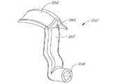
前述に加えて、図1、図13および図14を参照すると、アクチュエータ204は、外科用ステープリング器具100の第1側部116上の第1位置(図13)と、第2側部117上の第2位置(図14)と、第1および第2ハンドル部分102および104の近位端103および105に位置する中間位置(図1)との間で可動であり得る。いったんアクチュエータ204が第1および第2側部116,117の一方上の適所へ回転させられたら、アクチュエータ204は、遠位に前進させられ得る。様々な状況では、その結果、外科医は、アクチュエータ204を第1側部116、あるいは第2側部117に沿って遠位に動かすかどうか選択することができる。そのような状況は、アクチュエータ204が外科用器具の一方の側部に沿って遠位に移動させられるとき、もう一方の側部と比べて、例えば手術部位を取り囲む組織に影響を与えうる可能性が高い場合に、生じることがある。様々な実施形態では、図2および図3を参照すると、アクチュエータ204は、そのアクチュエータ204から延びるアーム206を含むことができ、アーム206は、プッシュバー202の近位端203に旋回可能に据え付けられ得る。ある実施形態では、図1、図13および図14を再度参照すると、外科用器具100は、第1側部116に沿って延びる第1スロット(不図示)、および第2側部117に沿って延びる第2スロット118を含むことができ、第1および第2スロットは、アクチュエータ204の少なくとも一部をスライド可能に受容するように構成され得る。少なくとも1つの実施形態では、第1および第2スロットの側壁は、アクチュエータ204が所定通路に沿って動かされ得るように、アクチュエータ204の動きを制限する、あるいは少なくとも制限することを助けることができる。図14を参照すると、例えば、第2スロット118は、アクチュエータ204が第2側部117に沿って遠位に動かされるときに、アクチュエータ204のアーム206が第1ハンドル部分と第2ハンドル部分との中間をスライドさせられ得るように、第1ハンドル部分102と第2ハンドル部分104との間で定められ得る。上記と同様に、第1スロットも、第1ハンドル部分と第2ハンドル部分との中間で定められ得る。様々な実施形態では、図13および図14を再度参照すると、外科用器具100は、中間スロット119をさらに含むことができ、中間スロット119はまた、アーム206、および/またはアクチュエータ204の任意の他の適切な部分が、中間スロット119内でスライドできるように構成され得る。少なくとも1つのそのような実施形態では、中間スロット119は、第1および第2スロットに接続することができ、それにより、アクチュエータ204がその中間位置に位置付けられると、アクチュエータ204がその第1位置および第2位置のいずれか一方へ動かされ得るようになっている。ある実施形態では、第1スロット、第2スロット117、および中間スロット119は、互いに対して平行、または少なくとも実質的に平行であることができ、ならびに/あるいは、同一面内に置かれることができるが、スロットの1つ以上が他のスロットと平行でない、および/または異なる面内に置かれる、他の実施形態が想到される。さらに、図示された実施形態の第1および第2側部は、外科用器具100の反対側に位置しているが、例えば第1および第2スロットが隣接する側部および/または互いに正反対でない側部に位置する、他の実施形態が想到される。さらに、丸い部分および/または弓形部分を有する器具など、ステープリング器具の側部が容易に識別できない、他の実施形態が想到される。 In addition to the foregoing, referring to FIGS. 1, 13, and 14, the
様々な実施形態では、前述に加えて、外科用ステープリング器具100は、アクチュエータ204およびそれに対応してステープルスレッド組立体160が早まって前進させられることを防ぐ、あるいは少なくとも抑制することができるロック機構をさらに含むことができる。少なくとも1つの実施形態では、ロック機構は、ラッチ機構180が閉鎖された位置または少なくとも部分的に閉鎖された位置へ動かされる前に、アクチュエータ204が遠位に前進させられることを防ぐ、あるいは少なくとも抑制するように構成され得る。ある実施形態では、概して図5を参照すると、外科用ステープリング器具100は、ロック機構220をさらに含むことができ、このロック機構220は、アクチュエータ204と係合させられ得、また、ラッチ機構180が完全な開放位置(図5)および/または少なくとも実質的な開放位置にある間、アクチュエータ204と係合させられたままであることができる。様々な実施形態では、ロック機構220は、ロック222を含むことができ、このロック222は、例えばロックバネ224によってロック222に加えられる付勢力によりアクチュエータ204との係合へ付勢され得る。少なくとも1つのそのような実施形態では、アクチュエータ204は、ロック222の少なくとも一部分を受容するように構成され得る、1つ以上の溝、チャネル、またはスロット(不図示)を含むことができる。使用の際、ロック機構220は、ラッチ機構180がその完全に閉鎖された位置(図7)および/または少なくとも実質的に閉鎖された位置へ動かされるまで、アクチュエータ204を適所に保持することができる。そのような状況では、少なくとも1つの実施形態では、ラッチ機構180は、ロック機構220に係合し、かつロック222をアクチュエータ204から係合解除するように構成され得る。少なくとも1つのそのような実施形態では、図5〜図7を参照すると、ラッチ機構180は、カム183をさらに含むことができ、このカム183は、ラッチ機構180がその閉鎖された位置へ動かされると、ロック222上のカム面223に係合し、その結果、ロック222をアクチュエータ204から離れるようにスライドさせる、および/または別様に動かすように、構成され得る。様々な実施形態では、カム183は、ラッチカバー186および/またはラッチフレーム184から延びる壁部、リブ、および/または隆起部を含むことができる。いずれの場合でも、いったんロック222がアクチュエータ204から十分に係合解除されたら、少なくとも1つの実施形態では、アクチュエータ204は、図1に図示されているその中間位置から、図13および図14に図示されているような第1位置および第2位置の一方へ動かされ得る。 In various embodiments, in addition to the foregoing, the
前述されたように、ロック機構220は、ラッチ機構180が例えば閉鎖された位置および/または部分的に閉鎖された位置など所定位置へ動かされる前に、駆動バー202が遠位に前進させられることを防ぐ、あるいは少なくとも抑制するように構成され得る。有利なことに、ロック機構220はまた、第1ハンドル部分102および第2ハンドル部分104が共に組み合わせられる前に、ステープルスレッド組立体160が前進させられることを防ぐ、あるいは少なくとも抑制することができる。事実上、ロック機構220は、アンビル130とステープルカートリッジ150との中間に位置付けられた組織が、アンビル130およびステープルカートリッジ150がその組織に対して適切に位置付けられる前に、切断および/またはステープリングされることを防ぐことができる。また、事実上、ロック機構220は、適切なクランプ力が組織にかけられる前に、ステープルが組織へ配備されることを防ぐことができる。いずれの場合でも、ラッチ機構180がその完全な開放位置および/または部分的な開放位置へ戻されるとき、カム183はロック222から離れるように動かされ得、それによりロックバネ124は、ロック222を再度アクチュエータ204との係合へ付勢することができるようになっている。様々な他の実施形態では、図15および図16を参照すると、ロック機構220’は、カム面223’およびそれに加えてロック222’の相対運動を制限することができる停止部226’を含むロック222’を含むことができる。少なくとも1つの実施形態では、カム183は、例えば、カム面223’に接触するように構成され得、カム面223’の輪郭付けされた、傾斜された、および/または角度を付けられた、表面のため、カム183は、図16に図示されているようにロック222’を遠位に駆動するように構成され得る。ロック222’から延びるピン228’が、ピン228’がアクチュエータ204’内の開口部229’の内部に位置付けられている第1位置(図15)と、ピン228’が開口部229’から十分に取り外された第2位置(図16)との間で、動かされ得るように、ロック222’は、遠位に駆動され得る。様々な実施形態では、停止部226’は、ロック222’が遠位に駆動されて、いったんロック222’が十分に転置されたら、停止部226’はカム183と接触することができるように、構成され得る。そのような実施形態では、停止部226’は、ロック222’の第2すなわち転置された位置を制御するように構成され得る。上述と同様に、アクチュエータ180がその閉鎖された位置から動かされて、カム183がロック機構220’から係合解除されると、ロックバネ224’は、ロック222’を再度アクチュエータ204’と係合するように動かすことができる。 As described above, the
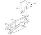
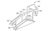
様々な実施形態では、前述されたように、発射アクチュエータは、プッシュバー、ステープルスレッド、および/または切断部材を第1位置と第2位置との間で動かすために利用され得る。これもまた前述されたように、例えば、プッシュバー組立体200は、例えばステープルスレッド組立体160などのステープルスレッド組立体を、近位位置(図10)と遠位位置との間で動かすために利用され得る。ある実施形態では、例えばステープルカートリッジ150などのステープルカートリッジは、その中に収容されたステープルスレッド組立体160を含むことができ、ステープルカートリッジがステープルカートリッジチャネル122に組み合わせられるか、または挿入されると、図10に図示されているように、ステープルスレッド組立体160は、遠位位置に位置付けられ得る。少なくとも1つのそのような実施形態では、図8〜図10を参照すると、ステープルカートリッジ150は、例えばステープルスレッド組立体160がその遠位位置にあるとき、切断部材164の少なくとも一部分を覆うように構成され得る、ハウジング170をさらに含むことができる。様々な実施形態では、ハウジング170は、例えば外科医が、例えば、ステープルカートリッジを取り扱うとき、ステープルカートリッジを外科用ステープラに挿入するとき、および/または外科用ステープラの2つ以上の部分を共に組み立てるときに、外科医を保護するように構成され得る。少なくとも1つのそのような実施形態では、切断エッジ165の少なくとも上方部分が、ステープルカートリッジ150のデッキすなわち上面158よりも上に、例えばハウジング170などの保護ハウジングがない状態で延びることができ、切断エッジ165の上方部分は、露出され得る。 In various embodiments, as described above, the firing actuator can be utilized to move the push bar, staple sled, and / or cutting member between a first position and a second position. As also described above, for example, the
様々な実施形態では、前述されたように、切断部材165は、スロット、またはチャネル156の内部に少なくとも部分的に位置付けられ得、そして図10に図示されているように、切断部材164の少なくとも上方すなわち上端部分が、デッキ158よりも上に延びることができる。少なくとも1つの実施形態では、図8〜図10を参照すると、ハウジング170は、ステープルカートリッジ本体152の第1部分157から延びる第1壁すなわち第1部分172、ステープルカートリッジ本体152の第2部分159から延びる第2壁すなわち第2部分174、および、第1壁172と第2壁174との間を延びる上壁すなわち上部分176を含むことができる。ある実施形態では、ハウジングは、ステープルカートリッジ本体から延びる唯一の支持壁すなわち支持部分、および、それに加えて、その支持壁すなわち支持部分から延びる上壁すなわち上部分を含んでもよい。他の実施形態では、ハウジングは、1以上の側壁すなわち側方部分を含み、上壁を含まなくてもよい。少なくとも1つのそのような実施形態では、ハウジングの側壁は、例えば、側壁が切断部材の上端よりも上に延び、あるいは、切断部材の切断エッジよりも上に少なくとも延びるように、構成され得る。いずれの場合でも、図10に図示されているように、切断部材164の少なくとも一部分は、ステープルスレッド組立体160がその近位位置にあるとき、上壁176の下側、および/または側壁172と側壁174との間に位置付けられ得る。ある実施形態では、切断部材164は、上壁176の下側に完全に位置付けられ得、および/またはハウジング170内部に完全に位置付けられ得る。少なくとも1つの実施形態では、切断部材164は、切断面165が遠位エッジ175および/または上壁176の近位エッジ177を越えて延びないように、上壁176の下側に位置付けられ得る。少なくとも1つの実施形態では、ハウジング170は、切断部材164および/またはステープルスレッド組立体160の任意の他の部分の近位移動を制限するように構成され得る、後方壁178を含むことができる。様々な実施形態では、例えばハウジング170の少なくとも一部分は、ステープルカートリッジ本体152と一体的に形成され得る。少なくとも1つのそのような実施形態では、第1壁172、第2壁174、上壁176、および/または後方壁178は、例えば、ステープルカートリッジ本体152が射出成型されるときに、形成され得る。ある実施形態では、ハウジング170の少なくとも一部分は、スナップ嵌め式、プレス嵌め式、および/または任意の他の適切な方法によりステープルカートリッジ本体152に組み合わせられ得る。 In various embodiments, as described above, the cutting
様々な実施形態では、前述に加えて、切断部材164は、平坦な、または少なくとも実質的に平坦な、本体により定められ得、この切断部材本体は、この本体の少なくとも片側に沿って延びるナイフエッジを有する。少なくとも1つのそのような実施形態では、第1壁172および/または第2壁174は、それら壁が、切断部材164の側面に対して平行、または少なくとも実質的に平行である、平坦な、または少なくとも実質的に平坦な、内面173を含むことができるように、構成および配列され得る。ある実施形態では、切断部材164は、壁172および174の内面173の間に密接に受容され得る。少なくとも1つのそのような実施形態では、壁172と壁174との間の距離は、スロット156の幅と同じ、または少なくとも実質的に同じであり得る。いずれの場合でも、ハウジングは、例えば、ハウジングの少なくとも一部分がスロット156の少なくとも一部分を覆うように延びるよう構成され得る。ある実施形態では、ハウジング170は、切断部材164および/または切断面165を完全に囲むすなわち取り囲むことができる。少なくとも1つの実施形態では、図示はされていないが、ハウジングは、切断部材がハウジングから出ることを可能にするために、少なくとも部分的に分離されうる、引き離されうる、および/または別様に変形されうる、分離部分および/または切開可能な部分を含むことができる。少なくとも1つのそのような実施形態では、組織切断面は、例えば、ハウジングに接触してハウジング壁を壊すおよび/または切開するように構成され得る。様々な実施形態では、ハウジング壁は、ハウジング壁の変形および/または切開を容易にするために薄い部分、厚みが減少された部分、切り込み印、および/または任意の他の構成を含むことができる。ある実施形態では、切断部材は、例えば、ハウジングを変形および/または切開するように構成され得る、1つ以上の追加の切断面および/またはアンビルを含むことができる。少なくとも1つの実施形態では、ハウジングは、例えばヒンジ部材および/または可撓性フラップなどの可動性部分および/または可撓性部分を含むことができ、可動性部分および/または可撓性部分は、十分に動くおよび/または曲がり、それにより切断部材が通過することができるように構成され得る。いずれの場合でも、切断部材が組織を切開するための任意の適切な構成を有することができ、保護ハウジングが切断部材を少なくとも部分的に囲むすなわち取り囲むための任意の適切な構成を有することができる、実施形態が想到される。さらに、前述されたように切断部材は鋭利なエッジを含むことができるが、例えば組織を切断するのに十分な電流が供給されるものなど、他の適切な切断部材が想到される。 In various embodiments, in addition to the foregoing, the cutting
前述されたように、ハウジング170は、切断部材がその近位位置にあるとき、切断部材を少なくとも部分的に覆う、囲む、および/または取り囲むように構成され得る。様々な実施形態では、切断部材は、例えば組織を切開するために遠位に前進させられ、その後、切断部材を再びハウジング170内部に位置付けるために近位に後退させられ得る。そのような実施形態では、切断部材は、ステープルカートリッジが、外科用ステープリング器具に組み合わせられるとき、および外科用ステープリング器具から取り外されるとき、ハウジング170により少なくとも部分的に覆われ得る。ある実施形態では、新しい、すなわち未使用のステープルカートリッジが、少なくとも部分的に使用されたステープルカートリッジを置換するためにステープルカートリッジチャネルに挿入され得る。少なくとも1つのそのような実施形態では、新しいステープルカートリッジは、その中に位置付けられた新しい切断部材および/またはステープルスレッド組立体を含むことができるが、前に使用された切断部材および/またはステープルスレッド組立体が、再び再使用されるために、使用済みステープルカートリッジから十分に引き戻されて、新しいステープルカートリッジの中に前進させられ得る、実施形態が想到される。新しい切断部材および/またはステープルスレッド組立体がそれぞれの新しいステープルカートリッジを提供される実施形態では、例えば、鋭利な切断エッジが、それぞれのステープルカートリッジと共に利用され得る。 As described above, the
様々な実施形態では、図示はされていないが、ステープルカートリッジは、切断部材が2つ以上の位置にあるとき、切断部材を少なくとも部分的に覆うように構成された2つ以上のハウジングを含むことができる。少なくとも1つの実施形態では、ステープルカートリッジは、例えば切断部材が近位位置にあるときに切断部材を少なくとも部分的に覆うように構成された近位ハウジング、およびそれに加えて、例えば切断部材が遠位位置にあるときに切断部材を少なくとも部分的に覆うように構成された遠位ハウジングを含むことができる。少なくとも1つのそのような実施形態では、切断部材は、ステープルカートリッジが外科用ステープリング器具に組み合わせられるとき、近位ハウジング内部に位置付けられ得、ある実施形態では、切断部材は、例えば切断部材がエンドエフェクタ内部に位置付けられた組織を横切した後に、遠位ハウジング内部へ前進させられ得る。そのような実施形態では、結果として、切断部材は、ステープルカートリッジが外科用ステープラから取り外されるとき、遠位ハウジング内部に少なくとも部分的に位置付けられ得る。そのような実施形態は、例えば血管がステープルカートリッジの近位ハウジングと遠位ハウジングとの中間に位置付けられている場合に特に有用であり得る。様々な実施形態では、図示はされていないが、切断部材は、遠位位置から近位位置に、および/または任意の他の適切な位置に、近位に動かされ得る。 In various embodiments, although not shown, the staple cartridge includes two or more housings configured to at least partially cover the cutting member when the cutting member is in two or more positions. Can do. In at least one embodiment, the staple cartridge includes a proximal housing configured, for example, to at least partially cover the cutting member when the cutting member is in a proximal position, and in addition, for example, the cutting member is distal. A distal housing configured to at least partially cover the cutting member when in position can be included. In at least one such embodiment, the cutting member can be positioned within the proximal housing when the staple cartridge is combined with a surgical stapling instrument, and in certain embodiments, the cutting member can be, for example, an end of the cutting member. After traversing tissue positioned within the effector, it can be advanced into the distal housing. In such embodiments, as a result, the cutting member can be positioned at least partially within the distal housing when the staple cartridge is removed from the surgical stapler. Such an embodiment may be particularly useful, for example, when the blood vessel is positioned intermediate the proximal and distal housings of the staple cartridge. In various embodiments, although not shown, the cutting member can be moved proximally from a distal position to a proximal position and / or from any other suitable position.
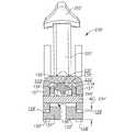
様々な実施形態では、前述に加えて、アンビル130は、例えば、アンビル130がステープルカートリッジ150に接近して対向させられたとき、ハウジング170の少なくとも一部分を受容するように構成され得る、1つ以上の開口部、スロット、または凹部179(図17)を含むことができる。少なくとも1つの実施形態では、アンビル130およびステープルカートリッジ150が、それらの間に干渉がない、または少なくとも実質的に干渉がない状態で、互いに対して動かされ得るように、ハウジング170と凹部179との間には十分な間隙が存在し得る。上記で概説されたように2つ以上の切断部材を有する実施形態では、対向アンビルがハウジングを受容するための2つ以上の対応する開口部を有することができる。様々な実施形態では、アンビルは、可動性切断部材、および、切断部材を少なくとも部分的に覆う、囲む、および/または取り囲むための少なくとも1つのハウジングを含むことができる。ある実施形態では、図示はされていないが、アンビルおよびステープルカートリッジの両方は、少なくとも1つの可動性切断部材、および/または、例えば切断部材が近位位置にあるとき、切断部材を少なくとも部分的に覆う、取り囲む、または囲うように構成された少なくとも1つのハウジングを含むことができる。 In various embodiments, in addition to the foregoing, the
上記で概説されたように、プッシュバー組立体200は、ステープルカートリッジ組立体150内部でステープルスレッド組立体160を動かすために遠位に前進させられ得る。様々な実施形態では、これもまた上記で概説されたように、ステープルスレッド162のウェッジ様カム面167は、ステープルドライバ168の傾斜面169と係合するように動かされ、順次および/または同時に、ステープルをステープルカートリッジ150からアンビル130に対して駆動して例えばB形構成など任意の適切な構成にステープルを成形することができる。少なくとも1つのそのような実施形態では、図17を参照すると、アンビル130は、ステープルを変形するように構成され得る、例えばステープルポケット132などの1つ以上のステープル成形面を含むことができる。ある実施形態では、アンビル130は、例えば、ステープルスレッド162、切断部材164、および/またはプッシュバー202の、少なくとも一部分をスライド可能に受容するように構成され得る、スロット、チャネル、または溝133をさらに含むことができる。少なくとも1つの実施形態では、図示はされていないが、アンビルは、アンビル内部に画定されたアンビルチャネルの内部にしっかりとおよび/または不動式に位置付けられ得るアンビルプレートを含むことができる。様々な他の実施形態では、図18および図19に図示され、以下でさらなる詳細が説明されるように、アンビル130は、アンビルチャネル136の内部に可動式に位置付けられたアンビルプレート134を含むことができる。ある実施形態では、アンビルチャネル136は、対向側壁137、およびそれに加えて、側壁137の間を延びる基部138を含むことができる。少なくとも1つの実施形態では、アンビル130は、例えば、アンビル130に組み合わせられた遠位ノーズ部分139をさらに含むことができ、ノーズ部分139は、例えばアンビルチャネル136内へプレス嵌めおよび/またはスナップ嵌めされるように構成され得、それにより、ノーズ部分139は、アンビルチャネル136内にしっかりと確保され得るようになっている。ある実施形態では、ノーズ部分139は、例えばゴムなどの軟質および/または柔軟な材料から構成され得、例えば手術部位内へのアンビル130の挿入を容易にすることができる任意の適切な形状を含むことができる。いくつかの実施形態では、図28を参照すると、ノーズ部分139’などのノーズ部分は、1つ以上の留め具139a’によりアンビルに確保され得る。同様に、図1を参照すると、ステープルカートリッジチャネルおよび/または例えばステープルカートリッジ150などのステープルカートリッジは、例えば、手術部位内へのステープルカートリッジ150の挿入を容易にすることができる、例えばノーズ部分153などのノーズ部分を含むことができる。 As outlined above, push
上記で示されたように、ステープルは、ステープルカートリッジから配備されて、アンビルに押し付けて変形させられ得る。様々な状況では、アンビル130のステープル成形面とステープルスレッド162との間の距離は、ステープルが変形させられる量を決定することができる。例えば、アンビル130のアンビルポケット132とステープルスレッド162の上面135(図10〜図12)との間の距離が比較的大きい場合、ステープルは、アンビルポケット132とスレッド面135との間の距離が比較的小さい場合と比較して、より少ない量、変形させられるであろう。それに対応して、アンビルポケット132とスレッド面135との間の距離が比較的小さい場合、ステープルは、アンビルポケット132とスレッド面135との間の距離が比較的大きい場合と比較して、より大きい量、変形させられるであろう。しばしば、アンビルポケット132とスレッド面135との間の距離は、ステープルの成形高さと称される。時折、ステープルの成形高さは、ステープルカートリッジの上面すなわちデッキと、アンビル上のステープル成形面との間で測定され得る。しかしながら、この適用の目的のために、ステープル成形高さに対する何らかの基準などが、適当な測定方法および/または任意の他の適切な測定方法の、一方または両方の測定方法を含めることができる。いずれの場合でも、以下でさらなる詳細が説明されるように、例えばステープリング器具100などの外科用ステープリング器具は、ステープル成形高さを調節するための手段を含むことができる。 As indicated above, the staples can be deployed from the staple cartridge and deformed against the anvil. In various situations, the distance between the staple forming surface of the
様々な実施形態では、前述に加えて、アンビルは、ステープルの成形高さを設定するためにステープルカートリッジに向かうよう、および/またはステープルカートリッジから離れるように、動かされ得る1つ以上の成形面を含むことができる。少なくとも1つの実施形態では、図17〜図23を参照すると、アンビル130は、アンビルチャネル136内部で可動式におよび/またはスライド可能に位置付けされ得る、アンビルプレート134を含むことができる。ある実施形態では、アンビル130は、1つ以上の保持ピンまたはガイドピン140をさらに含むことができ、アンビルプレート134は、ピン140の少なくとも一部分をスライド可能に受容するように構成された、1つ以上の保持スロットまたはガイドスロット141を含むことができる。少なくとも1つのそのような実施形態では、ピン140および/またはスロット141は、所定通路であって、アンビルプレート134がその所定通路に沿って動かされ得る、所定通路を定めるように構成され得る。図18を参照すると、ピン140およびスロット141は、アンビルプレート134が直線状または少なくとも実質的に直線状の通路に沿って動かされ得るように構成および配列され得、例えば直線状の通路は、軸142および143によって少なくとも部分的に定められ得る。アンビルプレートが例えば湾曲状および/または曲線的な通路などの非直線状の通路に沿って動かされ得る、他の実施形態が想到される。ある実施形態では、ピン140の少なくとも一部分は、側壁137の開口部144の内部に確保され得、少なくとも1つの実施形態では、ピン140は開口部144内部にプレス嵌めされ得る。いずれの場合でも、本明細書で説明されたように、ピン140は、例えば、アンビルプレート134がステープルカートリッジ150に向かうように、および/またはステープルカートリッジ150から離れるように動かされるときに、アンビルプレート134をガイドすることができる。 In various embodiments, in addition to the foregoing, the anvil has one or more forming surfaces that can be moved toward and / or away from the staple cartridge to set the forming height of the staples. Can be included. In at least one embodiment, referring to FIGS. 17-23,
様々な実施形態では、前述に加えて、例えばステープリング器具100などの外科用ステープリング器具は、例えばアンビルプレート134などのアンビルの一部分を、アンビル組立体の他の部分および/または対向するステープルカートリッジに対して、位置付けるように構成された、1つ以上の調節部材を含むことができる。ある実施形態では、図18および図19を参照すると、ステープリング器具100は、アンビルプレート134の動作範囲を制限するように構成され得る、アンビルプレート調節部材230を含むことができる。少なくとも1つのそのような実施形態では、図20および図21を参照すると、調節部材230は、第1位置でアンビルプレート134の中間に位置付けられ得、この第1位置では、調節部材230の第1表面またはステップ231が、アンビルチャネル136の基部138とアンビルプレート134の第1位置付け面145との中間に位置付けられる。そのような第1位置では、第1ステップ231は、アンビルプレート134とアンビルチャネル136との間の可能な、または許容された相対運動の量を定めることができる。例えば、アンビル130は前述されたように組織に対してクランピングされるとき、アンビルプレート134は、組織と接触し、第1位置付け面145が第1ステップ231に接触するまで基部138に向かって上方へスライドすることができる。いったん面145およびステップ231が接触すると、調節部材230は、アンビルプレート134が基部138に向かってさらに動くことを防ぐ、あるいは少なくとも抑制することができる。少なくとも1つのそのような実施形態では、その結果、調節部材230は、基部138とアンビルプレート134の組織接触面148との間の距離が第1距離234により定められ得るように、停止部として作用することができる。基部138は、本例において基準面として使用されるが、例えばアンビル130の他の部分、および/または対向するステープルカートリッジが基準面として使用され得る。調節部材230がその第1位置にある場合、前述されたように、調節部材230の第2面またはステップ232は、基部138とアンビルプレート134の第2位置付け面146との中間に位置付けられ得、それに加えて、第3面またはステップ233は、基部138と第3位置付け面147との中間に位置付けられ得る。図20を参照すると、調節部材230は、ステップ231、232および/または233の2つ以上の組を含むことができ、アンビルプレート134は、位置付け面145、146および/または147の2つ以上の組を含むことができる。第1ステップ231および第1位置付け面145は、アンビルプレート134の位置を制御するように構成されると前述されたが、調節部材230の第2および第3ステップ(232,233)、ならびにアンビルプレート134の第2および第3位置付け面(146,147)もまた、それぞれ、アンビルプレート134の位置を制御するように構成され得る。しかし、簡略にするために、本例は、アンビルプレート134の位置を制御する面として、第1面またはステップ231を参照して説明されるが、読者は、ステップ232および233もまた、アンビルプレート134の位置を制御できることを理解するであろう。 In various embodiments, in addition to the foregoing, a surgical stapling instrument, such as, for example, stapling
ある実施形態では、調節部材230の第1位置は、比較的小さい、すなわち短いステープル成形高さを提供することができる。他の実施形態では、図示はされていないが、調節部材の第1位置は、中間の、比較的大きな、および/または、任意の他の適切な、ステープル成形高さを提供することができる。調節部材の第1位置に関連する成形高さが適切である場合に、外科医は、前述されたように組織をステープリングおよび/または切開するように外科用ステープリング器具を使用し始めることができる。しかしながら、ステープル成形高さが不適切である場合、調節部材230は、アンビルプレート134がアンビル130とステープルカートリッジ150との中間に位置付けられた組織に接触するとき、アンビルプレート134が異なる距離、上方にスライドすることを可能にし得るように、外科医または他の臨床医は、調節部材230を動かすことができる。少なくとも1つのそのような状況では、アンビルプレート134が上方にスライドすることを許容されている距離は、より大きくなり、それにより、より大きな成形高さをステープルに提供することができる。それに対応して、他の状況では、例えば、アンビルプレート134が組織と接触しているとき、アンビルプレート134はより短い距離、上方へスライドし、それにより、より短いステープル成形高さを提供することができるように、調節部材は動かされ得る。用語「上方」等は、垂直方向上方を意味することができるが、この用語はそのように限定されず、むしろ「上方」は、例えば、アンビルの基部に向かう、および/またはステープルカートリッジから離れる、任意の方向を意味することができる。いずれの場合でも、調節部材230は、ステープル成形高さを増すために、図21に図示されている第1位置と、図22に図示されている第2位置との間で動かされ得る。図22中で矢印「P」により示されているように、調節部材230は、その第1位置と第2位置との間で調節部材230を動かすために、近位にスライドさせられ得るが、調節部材が、調節部材230を調節するために、遠位および/または任意の他の方向にスライドさせられ得る、実施形態が想到される。いったん調節部材230がその第2位置に動かされたら、図22を参照すると、第1面またはステップ231は、基部138とアンビルプレート134の第2位置付け面146との中間に位置付けられ得る。そのような第2位置では、第1ステップ231は、アンビルプレート134とアンビルチャネル136との間に許容される相対運動の量を再度、定めることができる。少なくとも1つの実施形態では、上記と同様に、調節部材230は、基部138とアンビルプレート134の組織接触面148との間の距離が第2距離235により定められ得るように、停止部として作用することができる。 In certain embodiments, the first position of the
前述に加えて、調節部材230は、再度ステープル成形高さを増すために、図22に図示されている第2位置と、図23に図示されている第3位置との間で動かされ得る。図23中で矢印「P」により示されているように、調節部材230は、調節部材230をその第2位置と第3位置との間で動かすために、近位にスライドさせられ得る。いったん調節部材230がその第3位置に動かされたら、図23を参照すると、第1面またはステップ231は、基部138と第3位置付け面147との中間に位置付けられ得る。そのような第3位置では、第1ステップ231は、アンビルプレート134とアンビルチャネル136との間での相対運動の量を再度、定めることができる。少なくとも1つの実施形態では、上記と同様に、調節部材230は、基部138とアンビルプレート134の組織接触面148との間の距離が第3距離236により定められ得るように、停止部として作用することができる。調節部材230は、3つの異なるステープル成形高さを提供するために前述されたように3つの位置の間で選択的に動かされ得るが、3つを超える異なるステープル成形高さを提供するために3つを超える位置の間で動かされ得る調節部材を含む、他の実施形態が想到される。例えば、調節部材は、4つのステープル成形高さを提供するために、4つの位置の間で可動であり得る。2つのステープル成形高さを提供するために2つの位置の間で動かされ得る調節部材を含む、さらなる実施形態が想到される。さらに、調節部材230の面またはステップ231,232および233は降順に配列されているが、それら面またはステップが昇順に配列される、他の配列が想到される。面またはステップが昇順または降順のいずれかに必ずしも配列されない、他の配列が想到される。同様に、アンビルプレート134の位置付け面145,146および147は、昇順、降順(図20)、および/または任意の他の適切な順番で配列され得る。さらに、調節部材230は、軸に沿ってスライドさせられ得るが、調節部材が、例えば湾曲状および/または曲線的な通路などの任意の適切な通路に沿って動かされ得る、他の実施形態が想到される。 In addition to the foregoing, the
前述されたように、図21を参照すると、調節部材230は、3つの面またはステップ231,232および233を含むことができ、一方でアンビルプレート134は、3つの対応する調節面145,146および147を含むことができる。例えば、調節部材230がその第1位置にあるとき、第1面231は、第1面231が第1調節面145に当接するか、または隣接するように位置付けられ得、第2面232は、第2面232が第2調節面146に当接するか、または隣接するように位置付けられ得、第3面233は、第3面233が第3調節面147に当接するか、または隣接するように位置付けられ得る。調節部材230がアンビルプレート134に対してスライドさせられると、前述されたように、そして図22および図23を参照すると、調節部材230の面231,232および233は、順次、アンビルプレート134の面145,146および147に対する指標とされ得る(indexed)。少なくとも1つのそのような実施形態では、調節部材は、アンビルプレート上の位置付け面の数と同数のステップを有することができる。調節部材がアンビルプレート上の位置付け面よりも多い数のステップを有する、他の実施形態が想到される。少なくとも1つのそのような実施形態では、アンビルプレートは、1つの位置付け面を含むことができ、調節部材のステップは、例えばアンビルプレートの上方運動を制限するために選択的に利用され得る。様々な実施形態では、概して調節部材230およびアンビルプレート134を参照すると、アンビルプレートは、例えば位置付け面145などの1つの位置付け面を含んでよく、例えば、調節部材230のステップ231,232および223は、基部138と位置付け面145との中間に選択的に位置付けられ得る。そのような実施形態では、第1ステップ231は、第1ステープル成形高さを定めるためにアンビルプレート134の上方運動を停止させるか、または制限することができる第1厚さすなわち第1高さを有することができ、第2ステップ232は、第2ステープル成形高さを定めるためにアンビルプレート134の上方運動を停止させるか、または制限することができる第2厚さすなわち第2高さを有することができ、それに加えて、第3ステップ233は、第3ステープル成形高さを定めるためにアンビルプレート134の上方運動を停止させるか、または制限することができる第3厚さすなわち第3高さを有することができる。少なくとも1つの実施形態では、ステップ231,232および/または233の厚みすなわち高さは、調節部材230の背面237と、アンビルプレート134に接触することになるステップ(231,232,233)の面との間で測定され得る。様々な実施形態では、第1ステップ231と第2ステップ232との間の高さ、すなわち厚みにおける相違は、第2ステップ232と第3ステップ233との間の高さ、すなわち厚みにおける相違と同一、または少なくとも実質的に同一であり得る。少なくとも1つのそのような実施形態では、その結果、ステップ高さは、線形比率、または少なくとも実質的に線形の比率で増加することができる。代替実施形態では、第1ステップと第2ステップとの間の高さ、すなわち厚みにおける相違は、第2ステップと第3ステップとの間の高さ、すなわち厚みにおける相違とは異なり得る。少なくとも1つのそのような実施形態では、第1、第2および第3ステップは、高さ、すなわち厚みが線形比率で増加または減少しなくてもよく、むしろ、図示はされていないが、ステップは、高さ、すなわち厚みが非線形および/または幾何数列的な比率で増加または減少してもよい。 As described above, referring to FIG. 21,
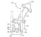
前述されたように、例えば調節部材230などの調節部材は、2つ以上の位置の間で可動であり得る。様々な実施形態では、外科用ステープリング器具は、調節部材を動かすように構成されたアクチュエータを含むことができる。少なくとも1つの実施形態では、図17〜図20を参照すると、外科用ステープリング器具100は、調節部材230に作用可能に取り付けられ得るアクチュエータ250を含むことができ、それにより、力がアクチュエータ250にかけられて調節部材230に伝達され得るようになっている。ある実施形態では、アクチュエータ250は、前述されたようにアンビル130内部で調節部材230を前進または後退させるために、例えば外科医によって把持されるように構成され得る把持部分すなわちハンドル252を含むことができる。ある実施形態では、把持部分252は、アクチュエータ本体251から延びることができ、アクチュエータ本体251は、調節部材230の少なくとも一部分を受容するように構成され得る、1つ以上の開口部、スロット、またはキャビティ253を含むことができる。少なくとも1つのそのような実施形態では、図19を参照すると、調節部材230は、その調節部材230から延びるロック254を含むことができ、ロック254の少なくとも一部分は、アクチュエータ本体251を調節部材230に確保させるために開口部253内部に受容され得る。様々な実施形態では、ロック254は、1つ以上の弾力性または可撓性のレッグ255を含むことができ、レッグ255は、開口部253に挿入されるとき変形させられるが、レッグ255の足部256が開口部253を通して十分に押し込まれた後、それらレッグ255の非収縮位置に弾力的に戻る、あるいは少なくとも部分的に戻ることができる。少なくとも1つのそのような実施形態では、足部256は、アクチュエータ本体251が調節部材230から分離されることを防ぐ、あるいは少なくとも抑制することができる。 As described above, an adjustment member, such as
様々な実施形態では、前述に加えて、外科用ステープリング器具100は、アクチュエータ250および/または調節部材230を適所に保持する、あるいは解放可能に保持するように構成され得る、戻り止め機構をさらに含むことができる。少なくとも1つの実施形態では、図19を参照すると、戻り止め機構260は、アクチュエータ250に取り付けられ得、少なくともいくつかの実施形態では、アクチュエータ本体251は、戻り止め部材260の戻り止め本体261を内部に受容および/または確保するように構成され得る1つ以上のチャネル、溝、または凹部257を含むことができる。少なくとも1つの実施形態では、戻り止め本体261は、例えば、戻り止め本体261をアクチュエータ251に固定するための1つ以上の留め具を受容するように構成され得る、1つ以上の開口部263および/または任意の他の適切なチャネル、スロット、もしくは溝を含むことができる。戻り止め部材260は、例えば第1フレーム部分110内の1つ以上の凹部、開口部、または溝101(図2〜図7)に係合するように構成され得る、戻り止めレッグ262をさらに含むことができる。より詳細には、図2および図3を参照すると、各側方フランジ128が、そこに画定された1つ以上の凹部101(101a,101bおよび101c)を含むことができ、戻り止めレッグ262は、戻り止めレッグ262が、凹部101内へスライドさせられたり凹部101外へスライドさせられたりすることができるように、側方フランジ128の上面に係合するように付勢され得る。図示された実施形態では、各側方フランジは、アクチュエータ250を第1の遠位位置、第2の中間位置、および第3の近位位置に取り外し可能に保持するように構成され得る、3つの凹部101を含むことができ、アクチュエータ250の第1、第2および第3の位置は、それぞれ前述された調節部材230の第1、第2および第3位置と対応することができる。例えば、アクチュエータ250がその第1の遠位位置にある場合、戻り止め部材260の戻り止めレッグ262は、アクチュエータ250および調節部材230をそれらの第1位置に取り外し可能に確保するように、凹部101a内部に位置付けられ得る。十分な力が加えられると、アクチュエータ250は、その第2位置へ近位に動かされ得、それにより、戻り止めレッグ162は、凹部101b内部に位置付けられて、アクチュエータ250および調節部材230はそれらの第2位置に確保されるようになっている。同様に、十分な力が加えられると、アクチュエータ250は、その第3位置へ近位に動かされ得、それにより、戻り止めレッグ162は、凹部101c内部に位置付けられて、アクチュエータ250および調節部材230は、それらの第3位置に確保されるようになっている。様々な実施形態では、戻り止めレッグ162は、アクチュエータ250がその第1位置および/または第2位置に戻され得るように、構成され得る。 In various embodiments, in addition to the foregoing,
前述されたように、調節部材230は、アクチュエータ250によって、2つ以上の位置の間の所定通路に沿って動かされ得る。様々な実施形態では、例えば、外科用ステープリング器具100は、調節部材230および/またはアクチュエータ250の運動を制御または制限するための1つ以上のガイドを含むことができる。いくつかの実施形態では、調節部材230は、アンビル130の側壁137が調節部材230をガイドすることができるように、側壁137の間に密接に受容され得る。少なくとも1つのそのような実施形態では、側壁137は、調節部材230の側方運動または側側運動(side-to-side movement)を制御または制限するように構成され得る。様々な実施形態では、戻り止め部材160の戻り止めレッグ162は弾力部材を含むことができ、この弾力部材は、上方付勢力すなわち上方牽引力を調節部材230にかけて、調節部材230を基部138に押し付けて、あるいは少なくとも基部138に隣接して、かつ側壁137の中間に、位置付けるように構成され得る。ある実施形態では、図19を参照すると、アンビル130の基部138は、ガイドスロット149をさらに含むことができ、このガイドスロット149は、ガイドスロット149が調節部材230およびアクチュエータ250の運動を制限することができるように、調節部材230および/またはアクチュエータ250の少なくとも一部分を内部に受容するように構成され得る。少なくとも1つのそのような実施形態では、調節部材230のロック254は、ガイドスロット149を通って延びるように構成され得、それにより、ロック254が前述されたようにアクチュエータ250の開口部253に挿入されると、アンビル130の基部138は、調節部材230とアクチュエータ250との中間に捕獲され得るようになっている。ある実施形態では、ガイドスロット149は、ロック254の運動を制限するように構成され得、それにより、調節部材230は、調節部材230がその第1位置すなわち最遠位位置にある場合、遠位に動かされることを妨げられる、あるいは少なくとも抑制されることができ、同様に、調節部材230がその第3の位置すなわち最近位位置にある場合、近位に動かされることを妨げられる、あるいは少なくとも抑制されることができるようになっている。 As previously described, the
様々な実施形態では、前述に加えて、例えば戻り止め部材260に類似する戻り止め部材は、第1ハンドル部分102および第2ハンドル部分104を互いから離れるように付勢するために利用され得る。少なくとも1つの実施形態では、図37を参照すると、外科用ステープリング器具100’は、アンビル130とステープルカートリッジ150との間にギャップが存在するよう、第1ハンドル部分102および第2ハンドル部分104を位置付けるように構成された戻り止め部材260’を含むことができる。上記で概説されたように、そのような特徴は、外科医が第1および第2ハンドル部分を互いから離れるように保持する必要なく、外科用器具を容易に操作することを可能にすることができる。ある実施形態では、戻り止め部材260’から延びる戻り止めレッグ262’が、フランジ128を接触することができ、圧迫されると、第1および第2ハンドル部分に付勢力をかけることができるように、戻り止め部材260’は、第2ハンドル部分104に十分に据え付けられ得る。図37に見出されるように、レッグ262’は、フランジ128の接触面101bに接触することができる。戻り止めレッグ262’を圧迫するために、ラッチ機構180は、ラッチアーム188がラッチ突出部131に係合してラッチ突出部131を少なくとも部分的に取り囲むことができるように、部分的に閉鎖された位置へ動かされ得る。この構成では、外科医が、器具を操作して、その器具の位置に満足した場合、ラッチ機構180を閉鎖された位置へ動かして、戻り止めレッグ262’をさらに圧迫することができる。上記と同様に、アクチュエータ250が前述されたようにその第1、第2および第3の位置の間で動かされるとき、レッグ262’が、それぞれ凹部101a、101bおよび101cに係合することができるように、戻り止め部材260’は、アクチュエータ250に固定されるか、または別様にアクチュエータ250と作用可能に係合させられ得る。少なくとも1つのそのような実施形態では、その結果、アクチュエータ250は、アクチュエータ250がその第1位置に対して遠位に位置付けられた前段階位置を有することができ、それに加えて、面101bは、前段階面を含むことができ、アクチュエータ250がその前段階位置にあるとき、レッグ262’が、この前段階面に対して位置付けられ得る。 In various embodiments, in addition to the foregoing, a detent member, eg, similar to
上記で概説されたように、調節部材は、外科用ステープリング器具により配備されるステープルの成形高さを調節するように、第1位置と第2位置との間でスライドすなわち並進運動させられ得る。様々な実施形態では、図示はされていないが、調節部材は、例えばアンビルプレートを対向するステープルカートリッジに向かうように、および/またはステープルカートリッジから離れるように確実に転置するように構成され得る。少なくとも1つのそのような実施形態では、外科用ステープリング器具は、例えば調節部材に対してアンビルプレートを位置付けるように構成された、バネなどの1つ以上の付勢部材を含むことができ、それにより、調節部材がその第1位置と第2位置との間で動かされるときに、調節部材は、第1および第2ステープル成形高さを設定するために、第1位置と第2位置と間でアンビルプレートを転置することができるようになっている。様々な実施形態では、上記の結果として、調節部材は、アンビルの一部分を適所にカム運動させる(cam)ように構成され得る。少なくとも1つのそのような実施形態では、調節部材は、アンビルプレートを確実に転置するために軸に沿ってスライドさせられ得る。他の実施形態では、回転可能な調節部材は、例えばアンビルプレートをステープルカートリッジに向かうように、および/またはステープルカートリッジから離れるように確実に転置するように構成され得る。 As outlined above, the adjustment member can be slid or translated between the first position and the second position to adjust the forming height of the staples deployed by the surgical stapling instrument. . In various embodiments, although not shown, the adjustment member may be configured to securely transpose, for example, the anvil plate toward and / or away from the opposing staple cartridge. In at least one such embodiment, the surgical stapling instrument can include one or more biasing members, such as springs, configured to position the anvil plate relative to the adjustment member, for example. When the adjustment member is moved between its first and second positions, the adjustment member is positioned between the first position and the second position to set the first and second staple forming heights. The anvil plate can be transposed. In various embodiments, as a result of the above, the adjustment member can be configured to cam a portion of the anvil in place. In at least one such embodiment, the adjustment member can be slid along the axis to securely transpose the anvil plate. In other embodiments, the rotatable adjustment member may be configured to securely transpose the anvil plate, for example, toward the staple cartridge and / or away from the staple cartridge.
前述に加えて、以下にさらなる詳細が説明されるように、調節部材は、ステープル成形高さを調節するために回転させられ得る。図24〜図36を参照すると、外科用器具100’は、上記と同様に、アンビル130’とステープルカートリッジ150’との中間の組織をクランピングするために利用され得る、第1ハンドル部分102’、第2ハンドル部分104’、およびラッチ機構180’を含むことができる。図25を参照すると、これもまた上記と同様に、ラッチ機構180’は、1つ以上の旋回軸ピン182’によって第1部分102’に旋回可能に連結され得、ラッチ機構180’は、第2部分104’に係合して、第1および第2ハンドル部分を共にラッチ掛けするように構成され得る、1つ以上のラッチアーム188’を含むことができる。これもまた上記と同様に、図25および図27を参照すると、外科用器具100’は、エンドエフェクタ120’内部で切断部材および/またはステープルスレッドを前進させるように構成され得るプッシュバー組立体200’をさらに含むことができる。少なくとも1つのそのような実施形態では、プッシュバー組立体200’は、近位端203’およびアクチュエータ204’を含むことができ、アクチュエータ204’は、近位端203’に回転可能に据え付けられ得、かつ、ステープリング器具100’の第1および第2側部に選択的に位置付けられ得る。様々な実施形態では、外科用ステープリング器具100’は、外科用ステープリング器具100に関連して説明された特徴と同一または同様の特徴を含むことができ、器具100と同一方法または同様の方法で操作され得、よって、この詳細は、ここでは繰り返さない。 In addition to the foregoing, the adjustment member can be rotated to adjust the staple forming height, as will be described in further detail below. Referring to FIGS. 24-36,
様々な実施形態では、図27を参照すると、外科用器具100’は、異なるステープル成形高さを提供するために、少なくとも第1および第2位置に選択的に位置付けられ得る、回転可能な調節部材230’を含むことができる。ある実施形態では、外科用器具100’は、調節部材230’に作用可能に接続され得るアクチュエータ250’を含むことができ、アクチュエータ250’が調節部材230’を少なくともその第1位置と第2位置との間で動かすことができるようになっている。少なくとも1つ実施形態では、図28を参照すると、アクチュエータ250’は、アクチュエータ本体251’、および把持部分すなわちハンドル252’を含むことができる。アクチュエータ本体251’は、調節部材230’の近位端238’を受容するように構成され得る開口部258’を含むことができ、それにより、回転動作、トルク、および/または力が、アクチュエータ250’と調節部材230’との間で伝達され得るようになっている。少なくとも1つのそのような実施形態では、図36を参照すると、開口部258’は、アクチュエータ本体251’とアクチュエータ230’との間の回転動作を伝達するように構成された、1つ以上の平坦駆動表面を含み得るプロファイル、および/または非円形プロファイルを含むことができる。ある実施形態では、開口部258’は、アクチュエータ230’の近位端238’を密接に受容するように寸法付けられ、かつ構成され得る。少なくとも1つの実施形態では、開口部258’は、プレス嵌めおよび/またはスナップ嵌め式に、近位端238’を受容するように構成され得る。様々な実施形態では、図28を再度参照すると、ハンドル部分104’は、1つ以上のスロット259’を含むことができ、そのスロット259’は、アクチュエータ本体251’の少なくとも一部分がそのスロットを通って延びることを可能にするように構成され得、それにより、把持部分252’が、ハンドル部分104’の少なくとも一部分が、把持部分252’とアクチュエータ本体251’との間に位置付けられている状態で、アクチュエータ本体251’に組み合わせられ得る。少なくとも1つのそのような実施形態では、第2ハンドル部分104’は、凹部253’をさらに含むことができ、この凹部253’は、把持部分252’の全てではなくとも、少なくとも一部分が凹部253’内部に位置付けられるように、構成され得る。ある実施形態では、凹部253’は、把持部分252’が第2ハンドル部分104’の上面よりも上に延びないように構成され得るが、他の実施形態では、把持部分252’の上部分が図30に図示されているように第2ハンドル部分104よりも上に延びることができ、それにより把持部分252’が外科医によって容易にアクセスされ得る。 In various embodiments, referring to FIG. 27, a rotatable adjustment member that can be selectively positioned in at least a first and a second position to provide the
様々な実施形態では、上記で概説されたように、調節部材は、外科用ステープラにより配備されたステープルの成形高さを調節するために、少なくとも第1位置と第2位置との間で回転可能であり得る。ある実施形態では、図28を参照すると、外科用ステープリング器具は、アンビル内部に回転可能に位置付けられた調節部材を含むことができ、調節部材は、可動性アンビル部分の相対運動を制限するように構成され得る。少なくとも1つのそのような実施形態では、外科用ステープリング器具100’は、保持ピンまたはガイドピン140’によりアンビルチャネル136’内部でスライド可能に確保され得るアンビルプレート134’を含むことができ、ガイドピン140’は、アンビルプレート134’が前述されたように組織と接触されると、アンビルプレート134’が上方にスライドすることができるように構成され得る。図27、図30および図31を参照すると、調節部材230’は、第1位置または第1向きに位置付けられ得、それによりアンビルチャネル136’内部でのアンビルプレート134’の上方運動を制限して、ステープルのステープル成形高さを決定することができるようになっている。少なくとも1つのそのような実施形態では、図30および図31を参照すると、調節部材230’は、アンビルチャネル136’の基部138’とアンビルプレート134’の位置付け面145’との中間に位置付けられ得る、対向する第1面231’を含むことができ、それにより、例えば、位置付け面145’が第1面231’の一方と接触すると、アンビルプレート134’の組織接触面148’が、アンビル130’上の基準面129’から第1距離234’離れて位置付けられ得るようになっている。それに対応して、成形面132’は、ステープルカートリッジから第1距離だけ離れて位置付けられ得、それにより、ステープルがステープルカートリッジから配備されるとき、ステープルは、第1ステープル高さまで変形させられ得る。前述に加えて、第1直径241’は、第1面231’の間に定められ得、第1直径241’は、アンビルチャネル136’内部でのアンビルプレート134’の最大上方位置を定めることができる。 In various embodiments, as outlined above, the adjustment member is rotatable between at least a first position and a second position to adjust the forming height of the staples deployed by the surgical stapler. It can be. In certain embodiments, referring to FIG. 28, the surgical stapling instrument can include an adjustment member rotatably positioned within the anvil, the adjustment member configured to limit relative movement of the movable anvil portion. Can be configured. In at least one such embodiment, the
上記で示されたように、調節部材230’は、ステープルの成形高さを調節するために回転させられ得る。様々な実施形態では、調節部材230’は、その第1位置または向き(図30および図31)と第2位置または向き(図32および図33)との間で回転させられ得る。少なくとも1つの実施形態では、図32および図33を参照すると、ハンドル252’は、調節部材230’をその第1位置と第2位置との間で動かすために、矢印「A」により示された方向に回転させられ得る。上記と同様に、アクチュエータ230’がその第2位置または向きにあるとき、アクチュエータ230’は、アンビルチャネル136’内部でのアンビルプレート134’の上方運動を制限してステープルのステープル成形高さを決定することができる。少なくとも1つのそのような実施形態では、図32および図33を参照すると、調節部材230’は、基部138’と位置付け面145’との中間に位置付けられ得る、対向する第2面232’を含むことができ、それにより、位置付け面145’が第2面232’の一方に接触すると、アンビルプレート134’の組織接触面148’が、例えば、基準面129’から第2距離235’離れて位置付けられ得るようになっている。それに対応して、成形面132’は、ステープルカートリッジから第2距離だけ離れて位置付けられ得、それにより、ステープルがステープルカートリッジから配備されると、ステープルは、第2ステープル高さまで変形させられ得るようになっている。様々な実施形態では、上記と同様に、第2直径242’が第2面232’の間に定められ得、第2直径242’は、アンビルチャネル136’内部でのアンビルプレート134’の最大上方位置を定めることができる。第1面231’および第2面232’は、平坦な、または少なくとも実質的に平坦な、面により定められ得るが、第1面231’および第2面232’が少なくとも部分的に弓形の、または湾曲された輪郭を含むことができる、他の実施形態が想到される。いずれの場合でも、図27を参照すると、調節部材230’は、アクチュエータ230’と保持ピン140’との間に間隙を提供するように構成され得る、1つ以上の間隙スロット240’を含んでよい。間隙スロット240’は、アクチュエータ230’がその第1位置、第2位置、および/または任意の他の適切な位置にあるとき、アクチュエータ230’と保持ピン140’との間に間隙を提供するように構成され得る。 As indicated above, the adjustment member 230 'can be rotated to adjust the forming height of the staples. In various embodiments, the adjustment member 230 'can be rotated between its first position or orientation (Figures 30 and 31) and a second position or orientation (Figures 32 and 33). In at least one embodiment, referring to FIGS. 32 and 33, handle 252 ′ is indicated by arrow “A” to move
様々な実施形態では、前述に加えて、調節部材230’は、その第1位置または向き(図30および図31)と第3位置または向き(図34および図35)との間で回転させられ得る。少なくとも1つの実施形態では、図34および図35を参照すると、ハンドル252’は、調節部材230’をその第1位置と第3位置との間で動かすために、矢印「B」により示されている方向に回転させられ得る。上記と同様に、アクチュエータ230’がその第3位置または向きにあるとき、アクチュエータ230’は、アンビルチャネル136’内部でのアンビルプレート134’の上方運動を制限して、ステープルのステープル成形高さを決定することができる。少なくとも1つのそのような実施形態では、図34および図35を参照すると、調節部材230’は、基部138’と位置付け面145’との中間に位置付けられ得る、対向する第3面233’を含むことができ、それにより、位置付け面145’が第3面233’の一方に接触すると、アンビルプレート134’の組織接触面148’は、例えば、基準面129’から第3距離236’だけ離れて位置付けられ得るようになっている。それに対応して、成形面132’は、ステープルカートリッジから第3距離だけ離れて位置付けられ得、それにより、ステープルがステープルカートリッジから配備されると、ステープルは、第3ステープル高さまで変形させられ得るようになっている。様々な実施形態では、上記と同様に、第3直径243’が、第3面233’の間で定められ得、第3直径243’は、アンビルチャネル136’内部でのアンビルプレート134’の最大上方位置を定めることができる。図34および図35を再度参照すると、第3面233’は、少なくとも部分的に弓形の輪郭により定められ得るが、第3面233’が、平坦な、または少なくとも実質的に平坦な輪郭を含むことができる、他の実施形態が想到される。少なくとも1つの実施形態では、調節部材230’は、弓形の第3面233’の間の最大距離すなわち直径が第3ステープル高さを定めるために利用され得るように、構成され得る。 In various embodiments, in addition to the foregoing, the
前述されたように、図30および図31を参照すると、調節部材230’は、外科用ステープリング器具100’により配備されるステープルのための第1成形高さを設定するために、第1位置または向きで位置付けられ得る。これもまた前述されたように、図32および図33を参照すると、アクチュエータ250’は、ステープルのための第2成形高さを設定するために、調節部材230’をその第2位置または向きへ動かすように利用され得る。このためには、少なくとも1つの実施形態では、ハンドル252’、およびそのハンドル252’に取り付けられた調節部材230’を矢印「A」により示されている方向に回転させることができる力が、ハンドル252’にかけられ得る。少なくとも1つの実施形態では、調節部材230’および/またはアクチュエータ250’は、調節部材230’が回転させられると、調節部材230’が例えば軸245’(図27)などの軸周りに回転させられ得るように、十分に確保され得る。少なくとも1つの実施形態では、図25を参照すると、プッシュバー組立体200’の近位端203’は、調節部材230’および/またはアクチュエータ250’の少なくとも一部分を内部に受容および/または確保するように構成され得る、1つ以上の溝、チャネル、または凹部205’を含むことができる。いずれの場合でも、図30〜図33に図示されているように、調節部材230’の第2位置または向きは、調節部材230’がその第1位置にある場合と比較すると、アンビルプレート134’がアンビルチャネル136’内部で、より大きな距離、スライドすることを可能にし得る。少なくとも1つの実施形態では、その結果、第2ステープル成形高さは、第1ステープル成形高さよりも高くなり得る。これもまた前述されたように、図34および図35を参照すると、アクチュエータ250’は、ステープルための第3成形高さを設定するために、調節部材230’をその第3位置または向きへ動かすように利用され得る。このためには、少なくとも1つの実施形態では、ハンドル252’、およびこのハンドル252’に取り付けられた調節部材230’を矢印「B」により示されている方向に回転させることができる力が、ハンドル252’にかけられ得る。図30、図31、図34、および図35に図示されているように、調節部材230’の第3位置または向きは、調節部材230’がその第1位置にある場合と比較すると、アンビルプレート134’がアンビルチャネル136’内部で、より小さい距離、スライドすることを可能にし得る。少なくとも1つの実施形態では、結果として、第1および第2ステープル成形高さは、第3ステープル成形高さよりも高くなり得る。少なくとも1つのそのような実施形態では、調節部材230’およびアクチュエータ250’の第1位置は、中間位置を表すことができ、調節部材230’は、その第1位置から直接、第2位置および第3位置へ選択的に動かされ得る。実際には、調節部材230’の第1位置は、中間ステープル高さを表すことができ、調節部材230’の第2および第3ステープル位置は、それぞれ、より高いステープル高さ、および、より低いステープル高さを表すことができる。ある実施形態では、図24を参照すると、外科用ステープリング器具100’は、選択され得るステープル成形高さ、または少なくとも相対成形高さを伝えるように構成され得る、1つ以上の印をその器具100’上に含むことができる。例えば、第2ハンドル部分104’は、中間の、すなわち第1のステープル高さを示すことができる第1の印245’、より高い、すなわち第2のステープル高さを示すことができる第2の印246’、および、それに加えて、より低い、すなわち第3のステープル高さを示すことができる第3の印247’を含むことができる。 As described above, with reference to FIGS. 30 and 31, the
様々な実施形態では、前述に加えて、第1面231’、第2面232’、および第3面233’のうちの1つ以上は、調節部材230’の周囲、すなわち外周を含む、すなわち定めることができ、あるいは、その外周を少なくとも部分的に含む、すなわち定めることができる。前述されたように、第1面、第2面、および第3面(231’,232’および233’)によりそれぞれ定められた、第1直径、第2直径、および第3直径(241’,242’および243’)ゆえに、調節部材230’の周囲、すなわち外周は、非円形であってよい。しかし、ある実施形態では、調節部材230’の周囲、すなわち外周は、対称性、実質的に対称性、および/または非対称性であってよい。様々な実施形態では、前述に加えて、調節部材は、例えば、アンビル130’の基部138’とアンビルプレート134’の調節面145’との中間に回転可能に位置付けられたカムを含むことができる。少なくとも1つのそのような実施形態では、例えば、第1面231’、第2面232’、および第3面233’のうちの1つ以上が、カムプロファイルを含む、すなわちカムプロファイルを定めることができ、このカムプロファイルは、上記と同様に、アンビルプレート134’を確実に位置付けするよう、および/または、停止部であって、アンビルプレート134’がその停止部に対して位置付けられ得る、停止部を提供するように、構成され得る。いずれの場合でも、図示はされていないが、調節部材が、外科用ステープリング器具により配備されるステープルのための2つ以上のステープル成形高さを設定するために、スライドおよび回転させられ得る、様々な実施形態が想到される。少なくとも1つそのような実施形態では、調節部材は、調節部材の長さに沿って定められ得るカムプロファイルを含むことができ、長さ方向運動および/または回転運動が、カムプロファイルを少なくとも第1位置と第2位置との間で動かすように利用され得る。 In various embodiments, in addition to the foregoing, one or more of the
様々な実施形態では、上記と同様に、外科用器具100’は、アクチュエータ250’を適所に保持する、あるいは少なくとも解放可能に保持するように構成された戻り止め機構をさらに含むことができる。少なくとも1つの実施形態では、図25および図26を参照すると、外科用器具100’は、戻り止め本体261’、および1つ以上の戻り止めレッグ262’を含む戻り止め部材260’をさらに含むことができる。図26を参照すると、戻り止め本体261’は、第2ハンドル部分104’の近位端105’の少なくとも一部分を受容するように構成され得る、1つ以上の溝、凹部、またはチャネル263’を含むことができ、それにより、戻り止め部材260’が適所に確保され得るようになっている。少なくとも1つのそのような実施形態では、近位端105’は、戻り止め部材260’を密接に受容するように構成され得る、1つ以上の溝、チャネル、または凹部265’をさらに含むことができる。ある実施形態では、例えば、チャネル263’などの、戻り止め本体261’の少なくとも一部分は、凹部265’内にプレス嵌め、スナップ嵌め、および/または別様に適切に確保され得る。これもまた図26に図示されているように、戻り止め部材260’の各戻り止めレッグ262’は、そこから延びる1つ以上の突出部264’を含むことができ、この突出部264’は、アクチュエータ本体251’に係合して、アクチュエータ250’を適所に解放可能に保持するように構成され得る。少なくとも1つの実施形態では、図36を参照すると、アクチュエータ本体251’は、突出部264’を受容するように構成され得る、1つ以上の凹部、または穴269’を含むことができる。突出部264’が凹部269’内部に位置付けられているとき、突出部は、例えば、突出部264’が凹部269’から転置させられるように十分な力がアクチュエータ250’にかけられるまで、アクチュエータ250’をその第1位置に保持するように構成され得る。より詳細には、アクチュエータ250’にかけられる力は、突出部264’に伝達されて、突出部264’と凹部269’との間の協働面により、突出部264’に関連する戻り止めレッグ262’は、アクチュエータ本体251’が戻り止めレッグ262’に対して動かされることを可能にするように、近位に曲げられ得るか、または動かされ得る。そのような近位運動を提供するために、図25を参照すると、凹部265’は、レッグ262’の少なくとも一部分を受容するようにそれぞれ構成され得る、細長い部分266’を含むことができ、それによりレッグ262’は、ハンドル部分104’に対して動くことができるようになっている。アクチュエータ250’が、その第2位置または第3位置のいずれかへ動かされると、アクチュエータ本体251’は、別のレッグ262’から延びる突出部264’に接触、そのレッグ262’を近位にゆがめることができ、いったんアクチュエータ250’がその第2位置または第3位置に置かれると、レッグ262’は、前方すなわち遠位に、はね返ることができ、それにより突出部264が、凹部269’の内部に固定され得るようになっている。少なくとも1つの実施形態では、前述に加えて、突出部264’と凹部269’の側壁との間の相互作用は、アクチュエータ250’が、例えばその第1位置、第2位置、および第3位置のうちの1つに固定式に保持され得、さらにアクチュエータ250’が十分な力を受けると動かされることを可能にし得るようなものであり得る。そのような実施形態では、戻り止め部材260’は、アクチュエータ250’およびそれに対応して調節部材230’が意図せずに転置されることを防ぐ、あるいは少なくとも抑制することができる。 In various embodiments, similar to the above, the surgical instrument 100 'can further include a detent mechanism configured to hold the actuator 250' in place, or at least releasably. In at least one embodiment, referring to FIGS. 25 and 26, the
本明細書に開示された装置は、1回使用後、廃棄されるように設計され得るか、または複数回使用されるように設計され得る。しかしながら、いずれの場合でも、本装置は、少なくとも1回使用した後、再使用のために再調整され得る。再調整は、装置の分解ステップ、それに続く特定部品の洗浄または置換のステップ、およびその後の再組立ステップの任意の組み合わせを含むことができる。特に、本装置は、分解され得、そして装置の任意の数の特定部品または部分が、任意の組み合わせで選択的に置換または除去され得る。特定部分の洗浄および/または置換の際、本装置は、その後の使用のために、再調整施設で、または手術処置の直前に外科チームによって、再組立され得る。当業者であれば、装置の再調整は、分解、洗浄/置換、および再組立のための様々な技術を利用できることを認識するであろう。そのような技術の使用、およびその結果の再調整された装置は、全て本願の範囲に含まれる。 The devices disclosed herein can be designed to be discarded after a single use, or can be designed to be used multiple times. In either case, however, the device can be reconditioned for reuse after at least one use. Reconditioning can include any combination of device disassembly steps, followed by specific component cleaning or replacement steps, and subsequent reassembly steps. In particular, the device can be disassembled and any number of specific parts or parts of the device can be selectively replaced or removed in any combination. Upon cleaning and / or replacement of specific parts, the device can be reassembled for subsequent use either at a reconditioning facility or by a surgical team immediately prior to a surgical procedure. One skilled in the art will recognize that reconditioning of the device can utilize a variety of techniques for disassembly, cleaning / replacement, and reassembly. The use of such techniques and the resulting readjusted device are all within the scope of this application.
好ましくは、本明細書で説明された発明は、手術前に処理されるだろう。第1に、新しいまたは使用済み器具が入手されて、必要に応じて洗浄される。その後、器具は殺菌され得る。一殺菌技術では、器具は、プラスチック製またはTYVEK製バッグなどの、閉鎖され密閉された容器の中に置かれる。その後、容器および器具は、γ線、X線、または高エネルギー電子などの、容器を貫通できる放射線の場に置かれる。放射線は、器具上および容器内のバクテリアを死滅させる。その後、殺菌された器具は、滅菌容器内で保管され得る。密閉された容器は、その容器が医療施設で開封されるまで、器具を無菌状態に保つ。 Preferably, the invention described herein will be processed before surgery. First, new or used equipment is obtained and cleaned as needed. The instrument can then be sterilized. In one sterilization technique, the instrument is placed in a closed and sealed container, such as a plastic or TYVEK bag. The container and instrument are then placed in a field of radiation that can penetrate the container, such as gamma rays, x-rays, or high energy electrons. Radiation kills bacteria on the instrument and in the container. The sterilized instrument can then be stored in a sterile container. The sealed container keeps the instrument sterile until it is opened in the medical facility.
本発明は、例示的デザインを有するように説明されてきたが、本発明は、本開示の精神および範囲内でさらに修正されてよい。したがって、本願は、その全般的原理を使用して、本発明のいかなる変形、使用、または改作を含むと意図される。さらに、本願は、本発明が属する技術分野における既知または通例の慣習に含まれるような本開示からのそのような逸脱を含むと意図される。 While this invention has been described as having an exemplary design, the present invention may be further modified within the spirit and scope of this disclosure. This application is therefore intended to cover any variations, uses, or adaptations of the invention using its general principles. Furthermore, this application is intended to cover such departures from the disclosure as included in known or customary practices in the technical field to which the present invention belongs.
Claims (17)
Translated fromJapaneseステープルカートリッジを受容するように構成されたステープルカートリッジチャネルを含む、第1ハンドル部分と、
アンビルを含む、第2ハンドル部分と、
第1駆動スロットと、
第2駆動スロットであって、前記第1および第2駆動スロットの少なくとも一方は、所定通路を定める、第2駆動スロットと、
駆動部材と、
前記駆動部材と作用可能に係合させられたアクチュエータであって、前記アクチュエータは、前記第1駆動スロットおよび前記第2駆動スロットへ選択的に可動であり、前記アクチュエータは、前記駆動部材を前記所定通路に沿って動かすように構成されている、アクチュエータと、
前記アクチュエータと選択的に係合可能なアクチュエータロックと、
前記第1ハンドル部分および前記第2ハンドル部分の一方に回転可能に連結されたラッチであって、前記ラッチは、開放位置と閉鎖された位置との間で可動であり、前記ラッチは、前記第1ハンドル部分および前記第2ハンドル部分の他方に係合するよう、かつ前記アンビルを前記ステープルカートリッジチャネルに対する適所へ動かすように、構成されており、前記ラッチは、前記ラッチが前記閉鎖された位置へ動かされると、前記アクチュエータロックに係合して前記アクチュエータロックを前記アクチュエータから係合解除するように構成されている、ラッチと、
を含む、外科用ステープラ。In surgical stapler,
A first handle portion including a staple cartridge channel configured to receive a staple cartridge;
A second handle portion including an anvil;
A first drive slot;
A second drive slot, wherein at least one of the first and second drive slots defines a predetermined passage; and
A drive member;
An actuator operably engaged with the drive member, wherein the actuator is selectively movable to the first drive slot and the second drive slot, and the actuator moves the drive member to the predetermined An actuator configured to move along the passageway;
An actuator lock selectively engageable with the actuator;
A latch rotatably coupled to one of the first handle portion and the second handle portion, wherein the latch is movable between an open position and a closed position; The latch is configured to engage the other of the one handle portion and the second handle portion, and to move the anvil into position relative to the staple cartridge channel, the latch being moved to the closed position. A latch configured to engage the actuator lock and disengage the actuator lock from the actuator when moved;
Surgical stapler including
前記アクチュエータは、前記第1駆動スロットと前記第2駆動スロットとを接続する中間駆動スロット内に位置付け可能である、外科用ステープラ。The surgical stapler according to claim 1, wherein
The surgical stapler, wherein the actuator is positionable within an intermediate drive slot connecting the first drive slot and the second drive slot.
前記アクチュエータロックは、前記ラッチが前記開放位置にある場合、前記中間駆動スロット内に前記アクチュエータを保持するように構成されている、外科用ステープラ。The surgical stapler according to claim 2, wherein
The surgical stapler, wherein the actuator lock is configured to retain the actuator in the intermediate drive slot when the latch is in the open position.
前記アクチュエータは、前記アクチュエータが前記中間駆動スロット内部に位置付けられているとき、前記第1駆動スロットおよび前記第2駆動スロットの一方へ選択可能に回転させられるように構成されており、
前記アクチュエータロックは、前記アクチュエータロックが前記アクチュエータと係合させられているとき、前記アクチュエータが前記第1駆動スロットおよび前記第2駆動スロットのいずれかへ回転することを防ぐように構成されている、外科用ステープラ。The surgical stapler according to claim 2, wherein
The actuator is configured to be selectively rotated to one of the first drive slot and the second drive slot when the actuator is positioned within the intermediate drive slot;
The actuator lock is configured to prevent the actuator from rotating to either the first drive slot or the second drive slot when the actuator lock is engaged with the actuator. Surgical stapler.
アクチュエータロックは、前記ラッチが前記開放位置にあるとき、前記第1駆動スロットと前記第2駆動スロットとの中間の適所に前記アクチュエータを保持するように構成されている、外科用ステープラ。The surgical stapler according to claim 1, wherein
A surgical stapler, wherein the actuator lock is configured to hold the actuator in place intermediate the first drive slot and the second drive slot when the latch is in the open position.
前記アクチュエータロックを前記アクチュエータと係合させるように付勢するよう構成されたロックバネ、
をさらに含む、外科用ステープラ。The surgical stapler according to claim 1, wherein
A lock spring configured to bias the actuator lock to engage the actuator;
A surgical stapler.
前記駆動部材は、切断部材およびステープルスレッドの少なくとも一方を含む、外科用ステープラ。The surgical stapler according to claim 1, wherein
The surgical stapler, wherein the drive member includes at least one of a cutting member and a staple thread.
第1ハンドル部分であって、
近位端、
遠位端、および、
ステープルカートリッジを受容するように構成されたステープルカートリッジチャネル、
を含む、第1ハンドル部分と、
第2ハンドル部分であって、
近位端、
遠位端、および、
アンビル、
を含む、第2ハンドル部分と、
駆動部材と、
前記駆動部材と作用可能に係合可能なアクチュエータであって、前記アクチュエータは、前記駆動部材を所定通路に沿って遠位に動かすように構成されている、アクチュエータと、
前記アクチュエータと選択的に係合可能なアクチュエータロックと、
前記第1ハンドル部分および前記第2ハンドル部分の一方に回転可能に連結されたラッチであって、前記ラッチは、前記ラッチが開放位置と閉鎖された位置との間で動かされると、前記第1ハンドル部分および前記第2ハンドル部分の他方に係合して、前記アンビルを前記ステープルカートリッジチャネルに対する適所に持ってくるように構成されており、前記ラッチは、前記ラッチが前記閉鎖された位置へ動かされると前記アクチュエータロックに係合するように、また、前記アクチュエータロックを前記アクチュエータから係合解除するように、構成されている、ラッチと、
を含む、外科用ステープラ。In surgical stapler,
A first handle portion,
Proximal end,
The distal end, and
A staple cartridge channel configured to receive a staple cartridge;
A first handle portion comprising:
A second handle part,
Proximal end,
The distal end, and
Anvil,
A second handle portion comprising:
A drive member;
An actuator operably engageable with the drive member, wherein the actuator is configured to move the drive member distally along a predetermined path;
An actuator lock selectively engageable with the actuator;
A latch rotatably coupled to one of the first handle portion and the second handle portion, wherein the latch is moved when the latch is moved between an open position and a closed position. Engaging the other of the handle portion and the second handle portion is configured to bring the anvil in position relative to the staple cartridge channel, the latch being moved to the closed position. A latch configured to engage the actuator lock when engaged and to disengage the actuator lock from the actuator;
Surgical stapler including
前記アクチュエータロックを前記アクチュエータと係合するように付勢するよう構成された、ロックバネ、
をさらに含む、外科用ステープラ。The surgical stapler according to claim 8, wherein
A lock spring configured to bias the actuator lock into engagement with the actuator;
A surgical stapler.
第1駆動スロットと、
第2駆動スロットと、
をさらに含み、
前記アクチュエータは、前記第1駆動スロットおよび前記第2駆動スロットへ選択的に可動であり、
前記第1駆動スロットおよび前記第2駆動スロットの少なくとも一方は、前記所定通路を定めており、
前記アクチュエータロックは、前記アクチュエータロックが前記アクチュエータと係合させられているとき、前記アクチュエータが前記第1駆動スロットおよび前記第2駆動スロットのいずれへも動くことを防ぐように構成されている、外科用ステープラ。The surgical stapler according to claim 8, wherein
A first drive slot;
A second drive slot;
Further including
The actuator is selectively movable to the first drive slot and the second drive slot;
At least one of the first drive slot and the second drive slot defines the predetermined passage;
The actuator lock is configured to prevent the actuator from moving into either the first drive slot or the second drive slot when the actuator lock is engaged with the actuator. Stapler.
第1駆動スロットと、
第2駆動スロットと、
をさらに含み、
前記アクチュエータは、前記第1駆動スロットおよび前記第2駆動スロットへ選択的に可動であり、
前記第1駆動スロットおよび前記第2駆動スロットの少なくとも一方は、前記所定通路を定めており、
アクチュエータロックは、前記ラッチが前記開放位置にあるとき、前記アクチュエータを前記第1駆動スロットと前記第2駆動スロットとの中間の適所に保持するように構成されている、外科用ステープラ。The surgical stapler according to claim 8, wherein
A first drive slot;
A second drive slot;
Further including
The actuator is selectively movable to the first drive slot and the second drive slot;
At least one of the first drive slot and the second drive slot defines the predetermined passage;
A surgical stapler, wherein the actuator lock is configured to hold the actuator in place intermediate the first drive slot and the second drive slot when the latch is in the open position.
前記駆動部材は、切断部材およびステープルスレッドの少なくとも一方を含む、外科用ステープラ。The surgical stapler according to claim 8, wherein
The surgical stapler, wherein the drive member includes at least one of a cutting member and a staple thread.
ステープルカートリッジを受容するように構成されたステープルカートリッジチャネルを含む、第1ハンドル部分と、
アンビルを含む、第2ハンドル部分と、
駆動部材と、
前記駆動部材と作用可能に係合可能なアクチュエータであって、前記アクチュエータは、前記駆動部材を所定通路に沿って動かすように構成されている、アクチュエータと、
前記アクチュエータと係合するように付勢される、アクチュエータロックと、
前記第1ハンドル部分および前記第2ハンドル部分の一方に回転可能に連結された、ラッチであって、前記ラッチは、開放位置と閉鎖された位置との間で回転可能であり、前記ラッチは、前記ラッチが前記開放位置と前記閉鎖された位置との間で動かされると、前記第1ハンドル部分および前記第2ハンドル部分の他方に係合するよう、かつ前記アンビルを前記ステープルカートリッジに対して位置付けるように、構成されており、前記ラッチは、前記ラッチが前記開放位置と前記閉鎖された位置との間で動かされると、前記アクチュエータロックを前記アクチュエータから係合解除するように構成されている、ラッチと、
を含む、外科用ステープラ。In surgical stapler,
A first handle portion including a staple cartridge channel configured to receive a staple cartridge;
A second handle portion including an anvil;
A drive member;
An actuator operably engageable with the drive member, wherein the actuator is configured to move the drive member along a predetermined path; and
An actuator lock biased to engage the actuator;
A latch rotatably coupled to one of the first handle portion and the second handle portion, the latch being rotatable between an open position and a closed position; When the latch is moved between the open position and the closed position, the anvil is positioned relative to the staple cartridge to engage the other of the first handle portion and the second handle portion. And the latch is configured to disengage the actuator lock from the actuator when the latch is moved between the open position and the closed position. A latch,
Surgical stapler including
前記アクチュエータロックを前記アクチュエータに係合するように付勢するよう構成された、ロックバネ、
をさらに含む、外科用ステープラ。The surgical stapler according to claim 13,
A lock spring configured to bias the actuator lock to engage the actuator;
A surgical stapler.
第1駆動スロットと、
第2駆動スロットと、
をさらに含み、
前記アクチュエータは、前記第1駆動スロットおよび前記第2駆動スロットへ選択的に可動であり、
前記第1駆動スロットおよび前記第2駆動スロットの少なくとも一方は、前記所定通路を定めており、
前記アクチュエータロックは、前記アクチュエータロックが前記アクチュエータと係合させられると、前記アクチュエータが前記第1駆動スロットおよび前記第2駆動スロットのいずれへも動くことを防ぐように構成されている、外科用ステープラ。The surgical stapler according to claim 13,
A first drive slot;
A second drive slot;
Further including
The actuator is selectively movable to the first drive slot and the second drive slot;
At least one of the first drive slot and the second drive slot defines the predetermined passage;
The actuator lock is configured to prevent the actuator from moving to either the first drive slot or the second drive slot when the actuator lock is engaged with the actuator. .
第1駆動スロットと、
第2駆動スロットと、
をさらに含み、
前記アクチュエータは、前記第1駆動スロットおよび前記第2駆動スロットへ選択的に可動であり、
前記第1駆動スロットおよび前記第2駆動スロットの少なくとも一方は、前記所定通路を定めており、
アクチュエータロックは、前記ラッチが前記開放位置にあるとき、前記アクチュエータを前記第1駆動スロットと前記第2駆動スロットとの中間の適所に保持するように構成されている、外科用ステープラ。The surgical stapler according to claim 13,
A first drive slot;
A second drive slot;
Further including
The actuator is selectively movable to the first drive slot and the second drive slot;
At least one of the first drive slot and the second drive slot defines the predetermined passage;
A surgical stapler, wherein the actuator lock is configured to hold the actuator in place intermediate the first drive slot and the second drive slot when the latch is in the open position.
前記駆動部材は、切断部材およびステープルスレッドの少なくとも一方を含む、外科用ステープラ。The surgical stapler according to claim 13,
The surgical stapler, wherein the drive member includes at least one of a cutting member and a staple thread.
Applications Claiming Priority (2)
| Application Number | Priority Date | Filing Date | Title |
|---|---|---|---|
| US12/234,113US7832612B2 (en) | 2008-09-19 | 2008-09-19 | Lockout arrangement for a surgical stapler |
| US12/234,113 | 2008-09-19 |
Publications (2)
| Publication Number | Publication Date |
|---|---|
| JP2010069307Atrue JP2010069307A (en) | 2010-04-02 |
| JP5384268B2 JP5384268B2 (en) | 2014-01-08 |
Family
ID=42201597
Family Applications (1)
| Application Number | Title | Priority Date | Filing Date |
|---|---|---|---|
| JP2009216532AActiveJP5384268B2 (en) | 2008-09-19 | 2009-09-18 | Surgical stapler lockout structure |
Country Status (3)
| Country | Link |
|---|---|
| JP (1) | JP5384268B2 (en) |
| BR (1) | BRPI0904975B1 (en) |
| RU (1) | RU2508913C2 (en) |
Cited By (440)
| Publication number | Priority date | Publication date | Assignee | Title |
|---|---|---|---|---|
| JP2014505508A (en)* | 2010-12-16 | 2014-03-06 | 蘇州天臣国際医療科技有限公司 | Linear cutter stapler |
| JP2014518678A (en)* | 2010-09-30 | 2014-08-07 | エシコン・エンド−サージェリィ・インコーポレイテッド | Tissue thickness compensator for surgical staplers with adjustable anvil |
| JP2014176672A (en)* | 2013-03-13 | 2014-09-25 | Covidien Lp | Surgical stapling apparatus |
| JP2017502726A (en)* | 2013-12-17 | 2017-01-26 | ▲蘇▼州天臣国▲際▼医▲療▼科技有限公司 | Linear cutter stapler |
| US9700310B2 (en) | 2013-08-23 | 2017-07-11 | Ethicon Llc | Firing member retraction devices for powered surgical instruments |
| US9706991B2 (en) | 2006-09-29 | 2017-07-18 | Ethicon Endo-Surgery, Inc. | Staple cartridge comprising staples including a lateral base |
| US9724094B2 (en) | 2014-09-05 | 2017-08-08 | Ethicon Llc | Adjunct with integrated sensors to quantify tissue compression |
| US9724098B2 (en) | 2012-03-28 | 2017-08-08 | Ethicon Endo-Surgery, Llc | Staple cartridge comprising an implantable layer |
| US9730697B2 (en) | 2012-02-13 | 2017-08-15 | Ethicon Endo-Surgery, Llc | Surgical cutting and fastening instrument with apparatus for determining cartridge and firing motion status |
| US9737303B2 (en) | 2004-07-28 | 2017-08-22 | Ethicon Llc | Articulating surgical stapling instrument incorporating a two-piece E-beam firing mechanism |
| US9750501B2 (en) | 2007-01-11 | 2017-09-05 | Ethicon Endo-Surgery, Llc | Surgical stapling devices having laterally movable anvils |
| US9750499B2 (en) | 2014-03-26 | 2017-09-05 | Ethicon Llc | Surgical stapling instrument system |
| US9757124B2 (en) | 2014-02-24 | 2017-09-12 | Ethicon Llc | Implantable layer assemblies |
| US9775614B2 (en) | 2011-05-27 | 2017-10-03 | Ethicon Endo-Surgery, Llc | Surgical stapling instruments with rotatable staple deployment arrangements |
| US9795383B2 (en) | 2010-09-30 | 2017-10-24 | Ethicon Llc | Tissue thickness compensator comprising resilient members |
| US9801627B2 (en) | 2014-09-26 | 2017-10-31 | Ethicon Llc | Fastener cartridge for creating a flexible staple line |
| US9808247B2 (en) | 2010-09-30 | 2017-11-07 | Ethicon Llc | Stapling system comprising implantable layers |
| US9808246B2 (en) | 2015-03-06 | 2017-11-07 | Ethicon Endo-Surgery, Llc | Method of operating a powered surgical instrument |
| US9814460B2 (en) | 2013-04-16 | 2017-11-14 | Ethicon Llc | Modular motor driven surgical instruments with status indication arrangements |
| US9814462B2 (en) | 2010-09-30 | 2017-11-14 | Ethicon Llc | Assembly for fastening tissue comprising a compressible layer |
| US9820738B2 (en) | 2014-03-26 | 2017-11-21 | Ethicon Llc | Surgical instrument comprising interactive systems |
| US9826978B2 (en) | 2010-09-30 | 2017-11-28 | Ethicon Llc | End effectors with same side closure and firing motions |
| US9826977B2 (en) | 2014-03-26 | 2017-11-28 | Ethicon Llc | Sterilization verification circuit |
| US9833242B2 (en) | 2010-09-30 | 2017-12-05 | Ethicon Endo-Surgery, Llc | Tissue thickness compensators |
| US9833241B2 (en) | 2014-04-16 | 2017-12-05 | Ethicon Llc | Surgical fastener cartridges with driver stabilizing arrangements |
| US9839420B2 (en) | 2010-09-30 | 2017-12-12 | Ethicon Llc | Tissue thickness compensator comprising at least one medicament |
| US9844374B2 (en) | 2014-12-18 | 2017-12-19 | Ethicon Llc | Surgical instrument systems comprising an articulatable end effector and means for adjusting the firing stroke of a firing member |
| US9844375B2 (en) | 2014-12-18 | 2017-12-19 | Ethicon Llc | Drive arrangements for articulatable surgical instruments |
| US9844376B2 (en) | 2014-11-06 | 2017-12-19 | Ethicon Llc | Staple cartridge comprising a releasable adjunct material |
| US9867618B2 (en) | 2008-02-14 | 2018-01-16 | Ethicon Llc | Surgical stapling apparatus including firing force regulation |
| US9872682B2 (en) | 2007-03-15 | 2018-01-23 | Ethicon Llc | Surgical stapling instrument having a releasable buttress material |
| US9883860B2 (en) | 2013-03-14 | 2018-02-06 | Ethicon Llc | Interchangeable shaft assemblies for use with a surgical instrument |
| US9895147B2 (en) | 2005-11-09 | 2018-02-20 | Ethicon Llc | End effectors for surgical staplers |
| US9895148B2 (en) | 2015-03-06 | 2018-02-20 | Ethicon Endo-Surgery, Llc | Monitoring speed control and precision incrementing of motor for powered surgical instruments |
| US9901342B2 (en) | 2015-03-06 | 2018-02-27 | Ethicon Endo-Surgery, Llc | Signal and power communication system positioned on a rotatable shaft |
| US9901345B2 (en) | 2008-02-14 | 2018-02-27 | Ethicon Llc | Stapling assembly |
| US9907620B2 (en) | 2012-06-28 | 2018-03-06 | Ethicon Endo-Surgery, Llc | Surgical end effectors having angled tissue-contacting surfaces |
| US9924944B2 (en) | 2014-10-16 | 2018-03-27 | Ethicon Llc | Staple cartridge comprising an adjunct material |
| US9924961B2 (en) | 2015-03-06 | 2018-03-27 | Ethicon Endo-Surgery, Llc | Interactive feedback system for powered surgical instruments |
| US9931118B2 (en) | 2015-02-27 | 2018-04-03 | Ethicon Endo-Surgery, Llc | Reinforced battery for a surgical instrument |
| US9943309B2 (en) | 2014-12-18 | 2018-04-17 | Ethicon Llc | Surgical instruments with articulatable end effectors and movable firing beam support arrangements |
| US9962158B2 (en) | 2008-02-14 | 2018-05-08 | Ethicon Llc | Surgical stapling apparatuses with lockable end effector positioning systems |
| US9962161B2 (en) | 2014-02-12 | 2018-05-08 | Ethicon Llc | Deliverable surgical instrument |
| US9974538B2 (en) | 2012-03-28 | 2018-05-22 | Ethicon Llc | Staple cartridge comprising a compressible layer |
| US9987003B2 (en) | 2007-06-04 | 2018-06-05 | Ethicon Llc | Robotic actuator assembly |
| US9987000B2 (en) | 2014-12-18 | 2018-06-05 | Ethicon Llc | Surgical instrument assembly comprising a flexible articulation system |
| US9993258B2 (en) | 2015-02-27 | 2018-06-12 | Ethicon Llc | Adaptable surgical instrument handle |
| US10004498B2 (en) | 2006-01-31 | 2018-06-26 | Ethicon Llc | Surgical instrument comprising a plurality of articulation joints |
| US10045781B2 (en) | 2014-06-13 | 2018-08-14 | Ethicon Llc | Closure lockout systems for surgical instruments |
| US10045776B2 (en) | 2015-03-06 | 2018-08-14 | Ethicon Llc | Control techniques and sub-processor contained within modular shaft with select control processing from handle |
| US10045778B2 (en) | 2008-09-23 | 2018-08-14 | Ethicon Llc | Robotically-controlled motorized surgical instrument with an end effector |
| US10052102B2 (en) | 2015-06-18 | 2018-08-21 | Ethicon Llc | Surgical end effectors with dual cam actuated jaw closing features |
| US10052044B2 (en) | 2015-03-06 | 2018-08-21 | Ethicon Llc | Time dependent evaluation of sensor data to determine stability, creep, and viscoelastic elements of measures |
| US10058963B2 (en) | 2006-01-31 | 2018-08-28 | Ethicon Llc | Automated end effector component reloading system for use with a robotic system |
| US10064621B2 (en) | 2012-06-15 | 2018-09-04 | Ethicon Llc | Articulatable surgical instrument comprising a firing drive |
| US10064688B2 (en) | 2006-03-23 | 2018-09-04 | Ethicon Llc | Surgical system with selectively articulatable end effector |
| US10070863B2 (en) | 2005-08-31 | 2018-09-11 | Ethicon Llc | Fastener cartridge assembly comprising a fixed anvil |
| US10070861B2 (en) | 2006-03-23 | 2018-09-11 | Ethicon Llc | Articulatable surgical device |
| US10076325B2 (en) | 2014-10-13 | 2018-09-18 | Ethicon Llc | Surgical stapling apparatus comprising a tissue stop |
| US10076326B2 (en) | 2015-09-23 | 2018-09-18 | Ethicon Llc | Surgical stapler having current mirror-based motor control |
| US10085748B2 (en) | 2014-12-18 | 2018-10-02 | Ethicon Llc | Locking arrangements for detachable shaft assemblies with articulatable surgical end effectors |
| US10085751B2 (en) | 2015-09-23 | 2018-10-02 | Ethicon Llc | Surgical stapler having temperature-based motor control |
| US10098642B2 (en) | 2015-08-26 | 2018-10-16 | Ethicon Llc | Surgical staples comprising features for improved fastening of tissue |
| US10098636B2 (en) | 2006-01-31 | 2018-10-16 | Ethicon Llc | Surgical instrument having force feedback capabilities |
| US10105139B2 (en) | 2015-09-23 | 2018-10-23 | Ethicon Llc | Surgical stapler having downstream current-based motor control |
| US10117649B2 (en) | 2014-12-18 | 2018-11-06 | Ethicon Llc | Surgical instrument assembly comprising a lockable articulation system |
| US10149683B2 (en) | 2008-10-10 | 2018-12-11 | Ethicon Llc | Powered surgical cutting and stapling apparatus with manually retractable firing system |
| US10172620B2 (en) | 2015-09-30 | 2019-01-08 | Ethicon Llc | Compressible adjuncts with bonding nodes |
| US10180463B2 (en) | 2015-02-27 | 2019-01-15 | Ethicon Llc | Surgical apparatus configured to assess whether a performance parameter of the surgical apparatus is within an acceptable performance band |
| US10188385B2 (en) | 2014-12-18 | 2019-01-29 | Ethicon Llc | Surgical instrument system comprising lockable systems |
| US10201363B2 (en) | 2006-01-31 | 2019-02-12 | Ethicon Llc | Motor-driven surgical instrument |
| US10206678B2 (en) | 2006-10-03 | 2019-02-19 | Ethicon Llc | Surgical stapling instrument with lockout features to prevent advancement of a firing assembly unless an unfired surgical staple cartridge is operably mounted in an end effector portion of the instrument |
| US10206676B2 (en) | 2008-02-14 | 2019-02-19 | Ethicon Llc | Surgical cutting and fastening instrument |
| US10211586B2 (en) | 2017-06-28 | 2019-02-19 | Ethicon Llc | Surgical shaft assemblies with watertight housings |
| US10213201B2 (en) | 2015-03-31 | 2019-02-26 | Ethicon Llc | Stapling end effector configured to compensate for an uneven gap between a first jaw and a second jaw |
| US10226249B2 (en) | 2013-03-01 | 2019-03-12 | Ethicon Llc | Articulatable surgical instruments with conductive pathways for signal communication |
| US10238386B2 (en) | 2015-09-23 | 2019-03-26 | Ethicon Llc | Surgical stapler having motor control based on an electrical parameter related to a motor current |
| US10245032B2 (en) | 2005-08-31 | 2019-04-02 | Ethicon Llc | Staple cartridges for forming staples having differing formed staple heights |
| US10245033B2 (en) | 2015-03-06 | 2019-04-02 | Ethicon Llc | Surgical instrument comprising a lockable battery housing |
| US10245029B2 (en) | 2016-02-09 | 2019-04-02 | Ethicon Llc | Surgical instrument with articulating and axially translatable end effector |
| US10258331B2 (en) | 2016-02-12 | 2019-04-16 | Ethicon Llc | Mechanisms for compensating for drivetrain failure in powered surgical instruments |
| US10258418B2 (en) | 2017-06-29 | 2019-04-16 | Ethicon Llc | System for controlling articulation forces |
| US10258333B2 (en) | 2012-06-28 | 2019-04-16 | Ethicon Llc | Surgical fastening apparatus with a rotary end effector drive shaft for selective engagement with a motorized drive system |
| US10265068B2 (en) | 2015-12-30 | 2019-04-23 | Ethicon Llc | Surgical instruments with separable motors and motor control circuits |
| US10265074B2 (en) | 2010-09-30 | 2019-04-23 | Ethicon Llc | Implantable layers for surgical stapling devices |
| US10271849B2 (en) | 2015-09-30 | 2019-04-30 | Ethicon Llc | Woven constructs with interlocked standing fibers |
| US10271846B2 (en) | 2005-08-31 | 2019-04-30 | Ethicon Llc | Staple cartridge for use with a surgical stapler |
| US10278780B2 (en) | 2007-01-10 | 2019-05-07 | Ethicon Llc | Surgical instrument for use with robotic system |
| US10292704B2 (en) | 2015-12-30 | 2019-05-21 | Ethicon Llc | Mechanisms for compensating for battery pack failure in powered surgical instruments |
| US10293100B2 (en) | 2004-07-28 | 2019-05-21 | Ethicon Llc | Surgical stapling instrument having a medical substance dispenser |
| US10299878B2 (en) | 2015-09-25 | 2019-05-28 | Ethicon Llc | Implantable adjunct systems for determining adjunct skew |
| US10307170B2 (en) | 2017-06-20 | 2019-06-04 | Ethicon Llc | Method for closed loop control of motor velocity of a surgical stapling and cutting instrument |
| US10314589B2 (en) | 2006-06-27 | 2019-06-11 | Ethicon Llc | Surgical instrument including a shifting assembly |
| USD851762S1 (en) | 2017-06-28 | 2019-06-18 | Ethicon Llc | Anvil |
| US10327769B2 (en) | 2015-09-23 | 2019-06-25 | Ethicon Llc | Surgical stapler having motor control based on a drive system component |
| US10327767B2 (en) | 2017-06-20 | 2019-06-25 | Ethicon Llc | Control of motor velocity of a surgical stapling and cutting instrument based on angle of articulation |
| US10335145B2 (en) | 2016-04-15 | 2019-07-02 | Ethicon Llc | Modular surgical instrument with configurable operating mode |
| USD854151S1 (en) | 2017-06-28 | 2019-07-16 | Ethicon Llc | Surgical instrument shaft |
| US10357247B2 (en) | 2016-04-15 | 2019-07-23 | Ethicon Llc | Surgical instrument with multiple program responses during a firing motion |
| US10363037B2 (en) | 2016-04-18 | 2019-07-30 | Ethicon Llc | Surgical instrument system comprising a magnetic lockout |
| US10363031B2 (en) | 2010-09-30 | 2019-07-30 | Ethicon Llc | Tissue thickness compensators for surgical staplers |
| US10363036B2 (en) | 2015-09-23 | 2019-07-30 | Ethicon Llc | Surgical stapler having force-based motor control |
| US10368864B2 (en) | 2017-06-20 | 2019-08-06 | Ethicon Llc | Systems and methods for controlling displaying motor velocity for a surgical instrument |
| US10368865B2 (en) | 2015-12-30 | 2019-08-06 | Ethicon Llc | Mechanisms for compensating for drivetrain failure in powered surgical instruments |
| US10376263B2 (en) | 2016-04-01 | 2019-08-13 | Ethicon Llc | Anvil modification members for surgical staplers |
| US10390841B2 (en) | 2017-06-20 | 2019-08-27 | Ethicon Llc | Control of motor velocity of a surgical stapling and cutting instrument based on angle of articulation |
| US10398433B2 (en) | 2007-03-28 | 2019-09-03 | Ethicon Llc | Laparoscopic clamp load measuring devices |
| US10398434B2 (en) | 2017-06-29 | 2019-09-03 | Ethicon Llc | Closed loop velocity control of closure member for robotic surgical instrument |
| US10405859B2 (en) | 2016-04-15 | 2019-09-10 | Ethicon Llc | Surgical instrument with adjustable stop/start control during a firing motion |
| US10413294B2 (en) | 2012-06-28 | 2019-09-17 | Ethicon Llc | Shaft assembly arrangements for surgical instruments |
| US10420549B2 (en) | 2008-09-23 | 2019-09-24 | Ethicon Llc | Motorized surgical instrument |
| US10420550B2 (en) | 2009-02-06 | 2019-09-24 | Ethicon Llc | Motor driven surgical fastener device with switching system configured to prevent firing initiation until activated |
| US10426463B2 (en) | 2006-01-31 | 2019-10-01 | Ehticon LLC | Surgical instrument having a feedback system |
| US10426481B2 (en) | 2014-02-24 | 2019-10-01 | Ethicon Llc | Implantable layer assemblies |
| US10426467B2 (en) | 2016-04-15 | 2019-10-01 | Ethicon Llc | Surgical instrument with detection sensors |
| US10426471B2 (en) | 2016-12-21 | 2019-10-01 | Ethicon Llc | Surgical instrument with multiple failure response modes |
| US10441285B2 (en) | 2012-03-28 | 2019-10-15 | Ethicon Llc | Tissue thickness compensator comprising tissue ingrowth features |
| US10448950B2 (en) | 2016-12-21 | 2019-10-22 | Ethicon Llc | Surgical staplers with independently actuatable closing and firing systems |
| US10448948B2 (en) | 2016-02-12 | 2019-10-22 | Ethicon Llc | Mechanisms for compensating for drivetrain failure in powered surgical instruments |
| US10456137B2 (en) | 2016-04-15 | 2019-10-29 | Ethicon Llc | Staple formation detection mechanisms |
| US10463370B2 (en) | 2008-02-14 | 2019-11-05 | Ethicon Llc | Motorized surgical instrument |
| US10485536B2 (en) | 2010-09-30 | 2019-11-26 | Ethicon Llc | Tissue stapler having an anti-microbial agent |
| US10485543B2 (en) | 2016-12-21 | 2019-11-26 | Ethicon Llc | Anvil having a knife slot width |
| US10492783B2 (en) | 2016-04-15 | 2019-12-03 | Ethicon, Llc | Surgical instrument with improved stop/start control during a firing motion |
| US10492785B2 (en) | 2016-12-21 | 2019-12-03 | Ethicon Llc | Shaft assembly comprising a lockout |
| US10499890B2 (en) | 2006-01-31 | 2019-12-10 | Ethicon Llc | Endoscopic surgical instrument with a handle that can articulate with respect to the shaft |
| US10499914B2 (en) | 2016-12-21 | 2019-12-10 | Ethicon Llc | Staple forming pocket arrangements |
| US10517595B2 (en) | 2016-12-21 | 2019-12-31 | Ethicon Llc | Jaw actuated lock arrangements for preventing advancement of a firing member in a surgical end effector unless an unfired cartridge is installed in the end effector |
| US10517590B2 (en) | 2007-01-10 | 2019-12-31 | Ethicon Llc | Powered surgical instrument having a transmission system |
| US10517594B2 (en) | 2014-10-29 | 2019-12-31 | Ethicon Llc | Cartridge assemblies for surgical staplers |
| US10524790B2 (en) | 2011-05-27 | 2020-01-07 | Ethicon Llc | Robotically-controlled surgical stapling devices that produce formed staples having different lengths |
| US10537325B2 (en) | 2016-12-21 | 2020-01-21 | Ethicon Llc | Staple forming pocket arrangement to accommodate different types of staples |
| US10568625B2 (en) | 2016-12-21 | 2020-02-25 | Ethicon Llc | Staple cartridges and arrangements of staples and staple cavities therein |
| US10568626B2 (en) | 2016-12-21 | 2020-02-25 | Ethicon Llc | Surgical instruments with jaw opening features for increasing a jaw opening distance |
| US10568652B2 (en) | 2006-09-29 | 2020-02-25 | Ethicon Llc | Surgical staples having attached drivers of different heights and stapling instruments for deploying the same |
| US10575868B2 (en) | 2013-03-01 | 2020-03-03 | Ethicon Llc | Surgical instrument with coupler assembly |
| US10588623B2 (en) | 2010-09-30 | 2020-03-17 | Ethicon Llc | Adhesive film laminate |
| US10588633B2 (en) | 2017-06-28 | 2020-03-17 | Ethicon Llc | Surgical instruments with open and closable jaws and axially movable firing member that is initially parked in close proximity to the jaws prior to firing |
| US10588632B2 (en) | 2016-12-21 | 2020-03-17 | Ethicon Llc | Surgical end effectors and firing members thereof |
| USD879809S1 (en) | 2017-06-20 | 2020-03-31 | Ethicon Llc | Display panel with changeable graphical user interface |
| USD879808S1 (en) | 2017-06-20 | 2020-03-31 | Ethicon Llc | Display panel with graphical user interface |
| US10617418B2 (en) | 2015-08-17 | 2020-04-14 | Ethicon Llc | Implantable layers for a surgical instrument |
| US10617412B2 (en) | 2015-03-06 | 2020-04-14 | Ethicon Llc | System for detecting the mis-insertion of a staple cartridge into a surgical stapler |
| US10617416B2 (en) | 2013-03-14 | 2020-04-14 | Ethicon Llc | Control systems for surgical instruments |
| US10617413B2 (en) | 2016-04-01 | 2020-04-14 | Ethicon Llc | Closure system arrangements for surgical cutting and stapling devices with separate and distinct firing shafts |
| US10624633B2 (en) | 2017-06-20 | 2020-04-21 | Ethicon Llc | Systems and methods for controlling motor velocity of a surgical stapling and cutting instrument |
| US10624861B2 (en) | 2010-09-30 | 2020-04-21 | Ethicon Llc | Tissue thickness compensator configured to redistribute compressive forces |
| US10631859B2 (en) | 2017-06-27 | 2020-04-28 | Ethicon Llc | Articulation systems for surgical instruments |
| US10646220B2 (en) | 2017-06-20 | 2020-05-12 | Ethicon Llc | Systems and methods for controlling displacement member velocity for a surgical instrument |
| US10660640B2 (en) | 2008-02-14 | 2020-05-26 | Ethicon Llc | Motorized surgical cutting and fastening instrument |
| US10667809B2 (en) | 2016-12-21 | 2020-06-02 | Ethicon Llc | Staple cartridge and staple cartridge channel comprising windows defined therein |
| US10675028B2 (en) | 2006-01-31 | 2020-06-09 | Ethicon Llc | Powered surgical instruments with firing system lockout arrangements |
| US10682134B2 (en) | 2017-12-21 | 2020-06-16 | Ethicon Llc | Continuous use self-propelled stapling instrument |
| US10687813B2 (en) | 2017-12-15 | 2020-06-23 | Ethicon Llc | Adapters with firing stroke sensing arrangements for use in connection with electromechanical surgical instruments |
| US10687806B2 (en) | 2015-03-06 | 2020-06-23 | Ethicon Llc | Adaptive tissue compression techniques to adjust closure rates for multiple tissue types |
| US10695062B2 (en) | 2010-10-01 | 2020-06-30 | Ethicon Llc | Surgical instrument including a retractable firing member |
| US10716614B2 (en) | 2017-06-28 | 2020-07-21 | Ethicon Llc | Surgical shaft assemblies with slip ring assemblies with increased contact pressure |
| US10716565B2 (en) | 2017-12-19 | 2020-07-21 | Ethicon Llc | Surgical instruments with dual articulation drivers |
| USD890784S1 (en) | 2017-06-20 | 2020-07-21 | Ethicon Llc | Display panel with changeable graphical user interface |
| US10729509B2 (en) | 2017-12-19 | 2020-08-04 | Ethicon Llc | Surgical instrument comprising closure and firing locking mechanism |
| US10729501B2 (en) | 2017-09-29 | 2020-08-04 | Ethicon Llc | Systems and methods for language selection of a surgical instrument |
| US10736628B2 (en) | 2008-09-23 | 2020-08-11 | Ethicon Llc | Motor-driven surgical cutting instrument |
| US10736636B2 (en) | 2014-12-10 | 2020-08-11 | Ethicon Llc | Articulatable surgical instrument system |
| US10743851B2 (en) | 2008-02-14 | 2020-08-18 | Ethicon Llc | Interchangeable tools for surgical instruments |
| US10743874B2 (en) | 2017-12-15 | 2020-08-18 | Ethicon Llc | Sealed adapters for use with electromechanical surgical instruments |
| US10743872B2 (en) | 2017-09-29 | 2020-08-18 | Ethicon Llc | System and methods for controlling a display of a surgical instrument |
| US10743875B2 (en) | 2017-12-15 | 2020-08-18 | Ethicon Llc | Surgical end effectors with jaw stiffener arrangements configured to permit monitoring of firing member |
| US10751076B2 (en) | 2009-12-24 | 2020-08-25 | Ethicon Llc | Motor-driven surgical cutting instrument with electric actuator directional control assembly |
| US10758230B2 (en) | 2016-12-21 | 2020-09-01 | Ethicon Llc | Surgical instrument with primary and safety processors |
| US10758229B2 (en) | 2016-12-21 | 2020-09-01 | Ethicon Llc | Surgical instrument comprising improved jaw control |
| US10758233B2 (en) | 2009-02-05 | 2020-09-01 | Ethicon Llc | Articulatable surgical instrument comprising a firing drive |
| US10765427B2 (en) | 2017-06-28 | 2020-09-08 | Ethicon Llc | Method for articulating a surgical instrument |
| US10765429B2 (en) | 2017-09-29 | 2020-09-08 | Ethicon Llc | Systems and methods for providing alerts according to the operational state of a surgical instrument |
| US10772629B2 (en) | 2017-06-27 | 2020-09-15 | Ethicon Llc | Surgical anvil arrangements |
| US10779821B2 (en) | 2018-08-20 | 2020-09-22 | Ethicon Llc | Surgical stapler anvils with tissue stop features configured to avoid tissue pinch |
| US10779903B2 (en) | 2017-10-31 | 2020-09-22 | Ethicon Llc | Positive shaft rotation lock activated by jaw closure |
| US10779824B2 (en) | 2017-06-28 | 2020-09-22 | Ethicon Llc | Surgical instrument comprising an articulation system lockable by a closure system |
| US10779825B2 (en) | 2017-12-15 | 2020-09-22 | Ethicon Llc | Adapters with end effector position sensing and control arrangements for use in connection with electromechanical surgical instruments |
| US10779820B2 (en) | 2017-06-20 | 2020-09-22 | Ethicon Llc | Systems and methods for controlling motor speed according to user input for a surgical instrument |
| US10779826B2 (en) | 2017-12-15 | 2020-09-22 | Ethicon Llc | Methods of operating surgical end effectors |
| US10796471B2 (en) | 2017-09-29 | 2020-10-06 | Ethicon Llc | Systems and methods of displaying a knife position for a surgical instrument |
| US10813639B2 (en) | 2017-06-20 | 2020-10-27 | Ethicon Llc | Closed loop feedback control of motor velocity of a surgical stapling and cutting instrument based on system conditions |
| US10828028B2 (en) | 2016-04-15 | 2020-11-10 | Ethicon Llc | Surgical instrument with multiple program responses during a firing motion |
| US10828033B2 (en) | 2017-12-15 | 2020-11-10 | Ethicon Llc | Handheld electromechanical surgical instruments with improved motor control arrangements for positioning components of an adapter coupled thereto |
| US10835330B2 (en) | 2017-12-19 | 2020-11-17 | Ethicon Llc | Method for determining the position of a rotatable jaw of a surgical instrument attachment assembly |
| US10842492B2 (en) | 2018-08-20 | 2020-11-24 | Ethicon Llc | Powered articulatable surgical instruments with clutching and locking arrangements for linking an articulation drive system to a firing drive system |
| US10842490B2 (en) | 2017-10-31 | 2020-11-24 | Ethicon Llc | Cartridge body design with force reduction based on firing completion |
| US10842491B2 (en) | 2006-01-31 | 2020-11-24 | Ethicon Llc | Surgical system with an actuation console |
| US10856870B2 (en) | 2018-08-20 | 2020-12-08 | Ethicon Llc | Switching arrangements for motor powered articulatable surgical instruments |
| US10856869B2 (en) | 2017-06-27 | 2020-12-08 | Ethicon Llc | Surgical anvil arrangements |
| US10869666B2 (en) | 2017-12-15 | 2020-12-22 | Ethicon Llc | Adapters with control systems for controlling multiple motors of an electromechanical surgical instrument |
| USD906355S1 (en) | 2017-06-28 | 2020-12-29 | Ethicon Llc | Display screen or portion thereof with a graphical user interface for a surgical instrument |
| US10881399B2 (en) | 2017-06-20 | 2021-01-05 | Ethicon Llc | Techniques for adaptive control of motor velocity of a surgical stapling and cutting instrument |
| US10881396B2 (en) | 2017-06-20 | 2021-01-05 | Ethicon Llc | Surgical instrument with variable duration trigger arrangement |
| USD907648S1 (en) | 2017-09-29 | 2021-01-12 | Ethicon Llc | Display screen or portion thereof with animated graphical user interface |
| USD907647S1 (en) | 2017-09-29 | 2021-01-12 | Ethicon Llc | Display screen or portion thereof with animated graphical user interface |
| US10888321B2 (en) | 2017-06-20 | 2021-01-12 | Ethicon Llc | Systems and methods for controlling velocity of a displacement member of a surgical stapling and cutting instrument |
| US10898183B2 (en) | 2017-06-29 | 2021-01-26 | Ethicon Llc | Robotic surgical instrument with closed loop feedback techniques for advancement of closure member during firing |
| US10903685B2 (en) | 2017-06-28 | 2021-01-26 | Ethicon Llc | Surgical shaft assemblies with slip ring assemblies forming capacitive channels |
| US10912559B2 (en) | 2018-08-20 | 2021-02-09 | Ethicon Llc | Reinforced deformable anvil tip for surgical stapler anvil |
| USD910847S1 (en) | 2017-12-19 | 2021-02-16 | Ethicon Llc | Surgical instrument assembly |
| US10932772B2 (en) | 2017-06-29 | 2021-03-02 | Ethicon Llc | Methods for closed loop velocity control for robotic surgical instrument |
| US10945731B2 (en) | 2010-09-30 | 2021-03-16 | Ethicon Llc | Tissue thickness compensator comprising controlled release and expansion |
| USD914878S1 (en) | 2018-08-20 | 2021-03-30 | Ethicon Llc | Surgical instrument anvil |
| US10966718B2 (en) | 2017-12-15 | 2021-04-06 | Ethicon Llc | Dynamic clamping assemblies with improved wear characteristics for use in connection with electromechanical surgical instruments |
| US10980537B2 (en) | 2017-06-20 | 2021-04-20 | Ethicon Llc | Closed loop feedback control of motor velocity of a surgical stapling and cutting instrument based on measured time over a specified number of shaft rotations |
| US10980539B2 (en) | 2015-09-30 | 2021-04-20 | Ethicon Llc | Implantable adjunct comprising bonded layers |
| US10987102B2 (en) | 2010-09-30 | 2021-04-27 | Ethicon Llc | Tissue thickness compensator comprising a plurality of layers |
| USD917500S1 (en) | 2017-09-29 | 2021-04-27 | Ethicon Llc | Display screen or portion thereof with graphical user interface |
| US10993716B2 (en) | 2017-06-27 | 2021-05-04 | Ethicon Llc | Surgical anvil arrangements |
| US11007004B2 (en) | 2012-06-28 | 2021-05-18 | Ethicon Llc | Powered multi-axial articulable electrosurgical device with external dissection features |
| US11006951B2 (en) | 2007-01-10 | 2021-05-18 | Ethicon Llc | Surgical instrument with wireless communication between control unit and sensor transponders |
| US11006955B2 (en) | 2017-12-15 | 2021-05-18 | Ethicon Llc | End effectors with positive jaw opening features for use with adapters for electromechanical surgical instruments |
| US11007022B2 (en) | 2017-06-29 | 2021-05-18 | Ethicon Llc | Closed loop velocity control techniques based on sensed tissue parameters for robotic surgical instrument |
| US11013511B2 (en) | 2007-06-22 | 2021-05-25 | Ethicon Llc | Surgical stapling instrument with an articulatable end effector |
| US11020112B2 (en) | 2017-12-19 | 2021-06-01 | Ethicon Llc | Surgical tools configured for interchangeable use with different controller interfaces |
| US11033267B2 (en) | 2017-12-15 | 2021-06-15 | Ethicon Llc | Systems and methods of controlling a clamping member firing rate of a surgical instrument |
| US11039836B2 (en) | 2007-01-11 | 2021-06-22 | Cilag Gmbh International | Staple cartridge for use with a surgical stapling instrument |
| US11039834B2 (en) | 2018-08-20 | 2021-06-22 | Cilag Gmbh International | Surgical stapler anvils with staple directing protrusions and tissue stability features |
| US11045192B2 (en) | 2018-08-20 | 2021-06-29 | Cilag Gmbh International | Fabricating techniques for surgical stapler anvils |
| US11045270B2 (en) | 2017-12-19 | 2021-06-29 | Cilag Gmbh International | Robotic attachment comprising exterior drive actuator |
| US11051813B2 (en) | 2006-01-31 | 2021-07-06 | Cilag Gmbh International | Powered surgical instruments with firing system lockout arrangements |
| US11051807B2 (en) | 2019-06-28 | 2021-07-06 | Cilag Gmbh International | Packaging assembly including a particulate trap |
| US11071545B2 (en) | 2014-09-05 | 2021-07-27 | Cilag Gmbh International | Smart cartridge wake up operation and data retention |
| US11071543B2 (en) | 2017-12-15 | 2021-07-27 | Cilag Gmbh International | Surgical end effectors with clamping assemblies configured to increase jaw aperture ranges |
| US11071554B2 (en) | 2017-06-20 | 2021-07-27 | Cilag Gmbh International | Closed loop feedback control of motor velocity of a surgical stapling and cutting instrument based on magnitude of velocity error measurements |
| US11076853B2 (en) | 2017-12-21 | 2021-08-03 | Cilag Gmbh International | Systems and methods of displaying a knife position during transection for a surgical instrument |
| US11083458B2 (en) | 2018-08-20 | 2021-08-10 | Cilag Gmbh International | Powered surgical instruments with clutching arrangements to convert linear drive motions to rotary drive motions |
| US11090075B2 (en) | 2017-10-30 | 2021-08-17 | Cilag Gmbh International | Articulation features for surgical end effector |
| US11090046B2 (en) | 2017-06-20 | 2021-08-17 | Cilag Gmbh International | Systems and methods for controlling displacement member motion of a surgical stapling and cutting instrument |
| US11133106B2 (en) | 2013-08-23 | 2021-09-28 | Cilag Gmbh International | Surgical instrument assembly comprising a retraction assembly |
| US11129680B2 (en) | 2017-12-21 | 2021-09-28 | Cilag Gmbh International | Surgical instrument comprising a projector |
| US11134944B2 (en) | 2017-10-30 | 2021-10-05 | Cilag Gmbh International | Surgical stapler knife motion controls |
| US11134942B2 (en) | 2016-12-21 | 2021-10-05 | Cilag Gmbh International | Surgical stapling instruments and staple-forming anvils |
| US11141153B2 (en) | 2014-10-29 | 2021-10-12 | Cilag Gmbh International | Staple cartridges comprising driver arrangements |
| US11147553B2 (en) | 2019-03-25 | 2021-10-19 | Cilag Gmbh International | Firing drive arrangements for surgical systems |
| US11147551B2 (en) | 2019-03-25 | 2021-10-19 | Cilag Gmbh International | Firing drive arrangements for surgical systems |
| US11154301B2 (en) | 2015-02-27 | 2021-10-26 | Cilag Gmbh International | Modular stapling assembly |
| US11172929B2 (en) | 2019-03-25 | 2021-11-16 | Cilag Gmbh International | Articulation drive arrangements for surgical systems |
| US11179150B2 (en) | 2016-04-15 | 2021-11-23 | Cilag Gmbh International | Systems and methods for controlling a surgical stapling and cutting instrument |
| US11197671B2 (en) | 2012-06-28 | 2021-12-14 | Cilag Gmbh International | Stapling assembly comprising a lockout |
| US11197670B2 (en) | 2017-12-15 | 2021-12-14 | Cilag Gmbh International | Surgical end effectors with pivotal jaws configured to touch at their respective distal ends when fully closed |
| US11202633B2 (en) | 2014-09-26 | 2021-12-21 | Cilag Gmbh International | Surgical stapling buttresses and adjunct materials |
| US11207065B2 (en) | 2018-08-20 | 2021-12-28 | Cilag Gmbh International | Method for fabricating surgical stapler anvils |
| US11207064B2 (en) | 2011-05-27 | 2021-12-28 | Cilag Gmbh International | Automated end effector component reloading system for use with a robotic system |
| US11213293B2 (en) | 2016-02-09 | 2022-01-04 | Cilag Gmbh International | Articulatable surgical instruments with single articulation link arrangements |
| US11219455B2 (en) | 2019-06-28 | 2022-01-11 | Cilag Gmbh International | Surgical instrument including a lockout key |
| US11224497B2 (en) | 2019-06-28 | 2022-01-18 | Cilag Gmbh International | Surgical systems with multiple RFID tags |
| US11224426B2 (en) | 2016-02-12 | 2022-01-18 | Cilag Gmbh International | Mechanisms for compensating for drivetrain failure in powered surgical instruments |
| US11224423B2 (en) | 2015-03-06 | 2022-01-18 | Cilag Gmbh International | Smart sensors with local signal processing |
| US11224427B2 (en) | 2006-01-31 | 2022-01-18 | Cilag Gmbh International | Surgical stapling system including a console and retraction assembly |
| US11224428B2 (en) | 2016-12-21 | 2022-01-18 | Cilag Gmbh International | Surgical stapling systems |
| US11229437B2 (en) | 2019-06-28 | 2022-01-25 | Cilag Gmbh International | Method for authenticating the compatibility of a staple cartridge with a surgical instrument |
| US11234698B2 (en) | 2019-12-19 | 2022-02-01 | Cilag Gmbh International | Stapling system comprising a clamp lockout and a firing lockout |
| US11241230B2 (en) | 2012-06-28 | 2022-02-08 | Cilag Gmbh International | Clip applier tool for use with a robotic surgical system |
| US11246592B2 (en) | 2017-06-28 | 2022-02-15 | Cilag Gmbh International | Surgical instrument comprising an articulation system lockable to a frame |
| US11246678B2 (en) | 2019-06-28 | 2022-02-15 | Cilag Gmbh International | Surgical stapling system having a frangible RFID tag |
| US11246590B2 (en) | 2005-08-31 | 2022-02-15 | Cilag Gmbh International | Staple cartridge including staple drivers having different unfired heights |
| US11253256B2 (en) | 2018-08-20 | 2022-02-22 | Cilag Gmbh International | Articulatable motor powered surgical instruments with dedicated articulation motor arrangements |
| US11253254B2 (en) | 2019-04-30 | 2022-02-22 | Cilag Gmbh International | Shaft rotation actuator on a surgical instrument |
| US11259803B2 (en) | 2019-06-28 | 2022-03-01 | Cilag Gmbh International | Surgical stapling system having an information encryption protocol |
| US11259799B2 (en) | 2014-03-26 | 2022-03-01 | Cilag Gmbh International | Interface systems for use with surgical instruments |
| US11259805B2 (en) | 2017-06-28 | 2022-03-01 | Cilag Gmbh International | Surgical instrument comprising firing member supports |
| US11266405B2 (en) | 2017-06-27 | 2022-03-08 | Cilag Gmbh International | Surgical anvil manufacturing methods |
| US11266409B2 (en) | 2014-04-16 | 2022-03-08 | Cilag Gmbh International | Fastener cartridge comprising a sled including longitudinally-staggered ramps |
| US11272927B2 (en) | 2008-02-15 | 2022-03-15 | Cilag Gmbh International | Layer arrangements for surgical staple cartridges |
| US11278279B2 (en) | 2006-01-31 | 2022-03-22 | Cilag Gmbh International | Surgical instrument assembly |
| US11284898B2 (en) | 2014-09-18 | 2022-03-29 | Cilag Gmbh International | Surgical instrument including a deployable knife |
| US11291451B2 (en) | 2019-06-28 | 2022-04-05 | Cilag Gmbh International | Surgical instrument with battery compatibility verification functionality |
| US11291440B2 (en) | 2018-08-20 | 2022-04-05 | Cilag Gmbh International | Method for operating a powered articulatable surgical instrument |
| US11291449B2 (en) | 2009-12-24 | 2022-04-05 | Cilag Gmbh International | Surgical cutting instrument that analyzes tissue thickness |
| US11291447B2 (en) | 2019-12-19 | 2022-04-05 | Cilag Gmbh International | Stapling instrument comprising independent jaw closing and staple firing systems |
| US11291441B2 (en) | 2007-01-10 | 2022-04-05 | Cilag Gmbh International | Surgical instrument with wireless communication between control unit and remote sensor |
| US11298125B2 (en) | 2010-09-30 | 2022-04-12 | Cilag Gmbh International | Tissue stapler having a thickness compensator |
| US11298127B2 (en) | 2019-06-28 | 2022-04-12 | Cilag GmbH Interational | Surgical stapling system having a lockout mechanism for an incompatible cartridge |
| US11298132B2 (en) | 2019-06-28 | 2022-04-12 | Cilag GmbH Inlernational | Staple cartridge including a honeycomb extension |
| US11304696B2 (en) | 2019-12-19 | 2022-04-19 | Cilag Gmbh International | Surgical instrument comprising a powered articulation system |
| US11304695B2 (en) | 2017-08-03 | 2022-04-19 | Cilag Gmbh International | Surgical system shaft interconnection |
| US11311290B2 (en) | 2017-12-21 | 2022-04-26 | Cilag Gmbh International | Surgical instrument comprising an end effector dampener |
| US11311294B2 (en) | 2014-09-05 | 2022-04-26 | Cilag Gmbh International | Powered medical device including measurement of closure state of jaws |
| US11317917B2 (en) | 2016-04-18 | 2022-05-03 | Cilag Gmbh International | Surgical stapling system comprising a lockable firing assembly |
| US11317913B2 (en) | 2016-12-21 | 2022-05-03 | Cilag Gmbh International | Lockout arrangements for surgical end effectors and replaceable tool assemblies |
| US11324503B2 (en) | 2017-06-27 | 2022-05-10 | Cilag Gmbh International | Surgical firing member arrangements |
| US11324501B2 (en) | 2018-08-20 | 2022-05-10 | Cilag Gmbh International | Surgical stapling devices with improved closure members |
| US11350928B2 (en) | 2016-04-18 | 2022-06-07 | Cilag Gmbh International | Surgical instrument comprising a tissue thickness lockout and speed control system |
| US11376098B2 (en) | 2019-06-28 | 2022-07-05 | Cilag Gmbh International | Surgical instrument system comprising an RFID system |
| US11382627B2 (en) | 2014-04-16 | 2022-07-12 | Cilag Gmbh International | Surgical stapling assembly comprising a firing member including a lateral extension |
| US11382638B2 (en) | 2017-06-20 | 2022-07-12 | Cilag Gmbh International | Closed loop feedback control of motor velocity of a surgical stapling and cutting instrument based on measured time over a specified displacement distance |
| US11399837B2 (en) | 2019-06-28 | 2022-08-02 | Cilag Gmbh International | Mechanisms for motor control adjustments of a motorized surgical instrument |
| US11399829B2 (en) | 2017-09-29 | 2022-08-02 | Cilag Gmbh International | Systems and methods of initiating a power shutdown mode for a surgical instrument |
| US11419606B2 (en) | 2016-12-21 | 2022-08-23 | Cilag Gmbh International | Shaft assembly comprising a clutch configured to adapt the output of a rotary firing member to two different systems |
| US11426251B2 (en) | 2019-04-30 | 2022-08-30 | Cilag Gmbh International | Articulation directional lights on a surgical instrument |
| US11426167B2 (en) | 2019-06-28 | 2022-08-30 | Cilag Gmbh International | Mechanisms for proper anvil attachment surgical stapling head assembly |
| US11432816B2 (en) | 2019-04-30 | 2022-09-06 | Cilag Gmbh International | Articulation pin for a surgical instrument |
| US11446029B2 (en) | 2019-12-19 | 2022-09-20 | Cilag Gmbh International | Staple cartridge comprising projections extending from a curved deck surface |
| US11452526B2 (en) | 2020-10-29 | 2022-09-27 | Cilag Gmbh International | Surgical instrument comprising a staged voltage regulation start-up system |
| US11452528B2 (en) | 2019-04-30 | 2022-09-27 | Cilag Gmbh International | Articulation actuators for a surgical instrument |
| US11464512B2 (en) | 2019-12-19 | 2022-10-11 | Cilag Gmbh International | Staple cartridge comprising a curved deck surface |
| USD966512S1 (en) | 2020-06-02 | 2022-10-11 | Cilag Gmbh International | Staple cartridge |
| US11464601B2 (en) | 2019-06-28 | 2022-10-11 | Cilag Gmbh International | Surgical instrument comprising an RFID system for tracking a movable component |
| US11464513B2 (en) | 2012-06-28 | 2022-10-11 | Cilag Gmbh International | Surgical instrument system including replaceable end effectors |
| USD967421S1 (en) | 2020-06-02 | 2022-10-18 | Cilag Gmbh International | Staple cartridge |
| US11471155B2 (en) | 2017-08-03 | 2022-10-18 | Cilag Gmbh International | Surgical system bailout |
| US11471157B2 (en) | 2019-04-30 | 2022-10-18 | Cilag Gmbh International | Articulation control mapping for a surgical instrument |
| US11478241B2 (en) | 2019-06-28 | 2022-10-25 | Cilag Gmbh International | Staple cartridge including projections |
| US11478247B2 (en) | 2010-07-30 | 2022-10-25 | Cilag Gmbh International | Tissue acquisition arrangements and methods for surgical stapling devices |
| US11484312B2 (en) | 2005-08-31 | 2022-11-01 | Cilag Gmbh International | Staple cartridge comprising a staple driver arrangement |
| US11497492B2 (en) | 2019-06-28 | 2022-11-15 | Cilag Gmbh International | Surgical instrument including an articulation lock |
| US11504122B2 (en) | 2019-12-19 | 2022-11-22 | Cilag Gmbh International | Surgical instrument comprising a nested firing member |
| US11517390B2 (en) | 2020-10-29 | 2022-12-06 | Cilag Gmbh International | Surgical instrument comprising a limited travel switch |
| US11517325B2 (en) | 2017-06-20 | 2022-12-06 | Cilag Gmbh International | Closed loop feedback control of motor velocity of a surgical stapling and cutting instrument based on measured displacement distance traveled over a specified time interval |
| US11523821B2 (en) | 2014-09-26 | 2022-12-13 | Cilag Gmbh International | Method for creating a flexible staple line |
| US11523822B2 (en) | 2019-06-28 | 2022-12-13 | Cilag Gmbh International | Battery pack including a circuit interrupter |
| US11523823B2 (en) | 2016-02-09 | 2022-12-13 | Cilag Gmbh International | Surgical instruments with non-symmetrical articulation arrangements |
| US11529139B2 (en) | 2019-12-19 | 2022-12-20 | Cilag Gmbh International | Motor driven surgical instrument |
| US11529137B2 (en) | 2019-12-19 | 2022-12-20 | Cilag Gmbh International | Staple cartridge comprising driver retention members |
| US11534259B2 (en) | 2020-10-29 | 2022-12-27 | Cilag Gmbh International | Surgical instrument comprising an articulation indicator |
| USD974560S1 (en) | 2020-06-02 | 2023-01-03 | Cilag Gmbh International | Staple cartridge |
| USD975278S1 (en) | 2020-06-02 | 2023-01-10 | Cilag Gmbh International | Staple cartridge |
| US11553971B2 (en) | 2019-06-28 | 2023-01-17 | Cilag Gmbh International | Surgical RFID assemblies for display and communication |
| USD975851S1 (en) | 2020-06-02 | 2023-01-17 | Cilag Gmbh International | Staple cartridge |
| USD975850S1 (en) | 2020-06-02 | 2023-01-17 | Cilag Gmbh International | Staple cartridge |
| US11559304B2 (en) | 2019-12-19 | 2023-01-24 | Cilag Gmbh International | Surgical instrument comprising a rapid closure mechanism |
| USD976401S1 (en) | 2020-06-02 | 2023-01-24 | Cilag Gmbh International | Staple cartridge |
| US11564686B2 (en) | 2017-06-28 | 2023-01-31 | Cilag Gmbh International | Surgical shaft assemblies with flexible interfaces |
| US11564682B2 (en) | 2007-06-04 | 2023-01-31 | Cilag Gmbh International | Surgical stapler device |
| US11571215B2 (en) | 2010-09-30 | 2023-02-07 | Cilag Gmbh International | Layer of material for a surgical end effector |
| US11576672B2 (en) | 2019-12-19 | 2023-02-14 | Cilag Gmbh International | Surgical instrument comprising a closure system including a closure member and an opening member driven by a drive screw |
| USD980425S1 (en) | 2020-10-29 | 2023-03-07 | Cilag Gmbh International | Surgical instrument assembly |
| US11607219B2 (en) | 2019-12-19 | 2023-03-21 | Cilag Gmbh International | Staple cartridge comprising a detachable tissue cutting knife |
| US11607239B2 (en) | 2016-04-15 | 2023-03-21 | Cilag Gmbh International | Systems and methods for controlling a surgical stapling and cutting instrument |
| US11617577B2 (en) | 2020-10-29 | 2023-04-04 | Cilag Gmbh International | Surgical instrument comprising a sensor configured to sense whether an articulation drive of the surgical instrument is actuatable |
| US11622763B2 (en) | 2013-04-16 | 2023-04-11 | Cilag Gmbh International | Stapling assembly comprising a shiftable drive |
| US11622766B2 (en) | 2012-06-28 | 2023-04-11 | Cilag Gmbh International | Empty clip cartridge lockout |
| US11627959B2 (en) | 2019-06-28 | 2023-04-18 | Cilag Gmbh International | Surgical instruments including manual and powered system lockouts |
| US11627960B2 (en) | 2020-12-02 | 2023-04-18 | Cilag Gmbh International | Powered surgical instruments with smart reload with separately attachable exteriorly mounted wiring connections |
| US11638582B2 (en) | 2020-07-28 | 2023-05-02 | Cilag Gmbh International | Surgical instruments with torsion spine drive arrangements |
| US11638587B2 (en) | 2019-06-28 | 2023-05-02 | Cilag Gmbh International | RFID identification systems for surgical instruments |
| US11648009B2 (en) | 2019-04-30 | 2023-05-16 | Cilag Gmbh International | Rotatable jaw tip for a surgical instrument |
| US11648005B2 (en) | 2008-09-23 | 2023-05-16 | Cilag Gmbh International | Robotically-controlled motorized surgical instrument with an end effector |
| US11653920B2 (en) | 2020-12-02 | 2023-05-23 | Cilag Gmbh International | Powered surgical instruments with communication interfaces through sterile barrier |
| US11653915B2 (en) | 2020-12-02 | 2023-05-23 | Cilag Gmbh International | Surgical instruments with sled location detection and adjustment features |
| US11653914B2 (en) | 2017-06-20 | 2023-05-23 | Cilag Gmbh International | Systems and methods for controlling motor velocity of a surgical stapling and cutting instrument according to articulation angle of end effector |
| US11660163B2 (en) | 2019-06-28 | 2023-05-30 | Cilag Gmbh International | Surgical system with RFID tags for updating motor assembly parameters |
| US11678877B2 (en) | 2014-12-18 | 2023-06-20 | Cilag Gmbh International | Surgical instrument including a flexible support configured to support a flexible firing member |
| US11678882B2 (en) | 2020-12-02 | 2023-06-20 | Cilag Gmbh International | Surgical instruments with interactive features to remedy incidental sled movements |
| US11684434B2 (en) | 2019-06-28 | 2023-06-27 | Cilag Gmbh International | Surgical RFID assemblies for instrument operational setting control |
| US11696757B2 (en) | 2021-02-26 | 2023-07-11 | Cilag Gmbh International | Monitoring of internal systems to detect and track cartridge motion status |
| US11696761B2 (en) | 2019-03-25 | 2023-07-11 | Cilag Gmbh International | Firing drive arrangements for surgical systems |
| US11701113B2 (en) | 2021-02-26 | 2023-07-18 | Cilag Gmbh International | Stapling instrument comprising a separate power antenna and a data transfer antenna |
| US11701111B2 (en) | 2019-12-19 | 2023-07-18 | Cilag Gmbh International | Method for operating a surgical stapling instrument |
| US11717291B2 (en) | 2021-03-22 | 2023-08-08 | Cilag Gmbh International | Staple cartridge comprising staples configured to apply different tissue compression |
| US11717289B2 (en) | 2020-10-29 | 2023-08-08 | Cilag Gmbh International | Surgical instrument comprising an indicator which indicates that an articulation drive is actuatable |
| US11717294B2 (en) | 2014-04-16 | 2023-08-08 | Cilag Gmbh International | End effector arrangements comprising indicators |
| US11723658B2 (en) | 2021-03-22 | 2023-08-15 | Cilag Gmbh International | Staple cartridge comprising a firing lockout |
| US11723662B2 (en) | 2021-05-28 | 2023-08-15 | Cilag Gmbh International | Stapling instrument comprising an articulation control display |
| US11723657B2 (en) | 2021-02-26 | 2023-08-15 | Cilag Gmbh International | Adjustable communication based on available bandwidth and power capacity |
| US11730473B2 (en) | 2021-02-26 | 2023-08-22 | Cilag Gmbh International | Monitoring of manufacturing life-cycle |
| US11737751B2 (en) | 2020-12-02 | 2023-08-29 | Cilag Gmbh International | Devices and methods of managing energy dissipated within sterile barriers of surgical instrument housings |
| US11737749B2 (en) | 2021-03-22 | 2023-08-29 | Cilag Gmbh International | Surgical stapling instrument comprising a retraction system |
| US11749877B2 (en) | 2021-02-26 | 2023-09-05 | Cilag Gmbh International | Stapling instrument comprising a signal antenna |
| US11744581B2 (en) | 2020-12-02 | 2023-09-05 | Cilag Gmbh International | Powered surgical instruments with multi-phase tissue treatment |
| US11744603B2 (en) | 2021-03-24 | 2023-09-05 | Cilag Gmbh International | Multi-axis pivot joints for surgical instruments and methods for manufacturing same |
| US11744583B2 (en) | 2021-02-26 | 2023-09-05 | Cilag Gmbh International | Distal communication array to tune frequency of RF systems |
| US11751869B2 (en) | 2021-02-26 | 2023-09-12 | Cilag Gmbh International | Monitoring of multiple sensors over time to detect moving characteristics of tissue |
| US11759202B2 (en) | 2021-03-22 | 2023-09-19 | Cilag Gmbh International | Staple cartridge comprising an implantable layer |
| US11766259B2 (en) | 2016-12-21 | 2023-09-26 | Cilag Gmbh International | Method of deforming staples from two different types of staple cartridges with the same surgical stapling instrument |
| US11766260B2 (en) | 2016-12-21 | 2023-09-26 | Cilag Gmbh International | Methods of stapling tissue |
| US11771419B2 (en) | 2019-06-28 | 2023-10-03 | Cilag Gmbh International | Packaging for a replaceable component of a surgical stapling system |
| US11779330B2 (en) | 2020-10-29 | 2023-10-10 | Cilag Gmbh International | Surgical instrument comprising a jaw alignment system |
| US11786239B2 (en) | 2021-03-24 | 2023-10-17 | Cilag Gmbh International | Surgical instrument articulation joint arrangements comprising multiple moving linkage features |
| US11786243B2 (en) | 2021-03-24 | 2023-10-17 | Cilag Gmbh International | Firing members having flexible portions for adapting to a load during a surgical firing stroke |
| US11793518B2 (en) | 2006-01-31 | 2023-10-24 | Cilag Gmbh International | Powered surgical instruments with firing system lockout arrangements |
| US11793522B2 (en) | 2015-09-30 | 2023-10-24 | Cilag Gmbh International | Staple cartridge assembly including a compressible adjunct |
| US11793514B2 (en) | 2021-02-26 | 2023-10-24 | Cilag Gmbh International | Staple cartridge comprising sensor array which may be embedded in cartridge body |
| US11793516B2 (en) | 2021-03-24 | 2023-10-24 | Cilag Gmbh International | Surgical staple cartridge comprising longitudinal support beam |
| US11806011B2 (en) | 2021-03-22 | 2023-11-07 | Cilag Gmbh International | Stapling instrument comprising tissue compression systems |
| US11812964B2 (en) | 2021-02-26 | 2023-11-14 | Cilag Gmbh International | Staple cartridge comprising a power management circuit |
| US11826012B2 (en) | 2021-03-22 | 2023-11-28 | Cilag Gmbh International | Stapling instrument comprising a pulsed motor-driven firing rack |
| US11826048B2 (en) | 2017-06-28 | 2023-11-28 | Cilag Gmbh International | Surgical instrument comprising selectively actuatable rotatable couplers |
| US11826132B2 (en) | 2015-03-06 | 2023-11-28 | Cilag Gmbh International | Time dependent evaluation of sensor data to determine stability, creep, and viscoelastic elements of measures |
| US11826042B2 (en) | 2021-03-22 | 2023-11-28 | Cilag Gmbh International | Surgical instrument comprising a firing drive including a selectable leverage mechanism |
| US11832816B2 (en) | 2021-03-24 | 2023-12-05 | Cilag Gmbh International | Surgical stapling assembly comprising nonplanar staples and planar staples |
| US11844520B2 (en) | 2019-12-19 | 2023-12-19 | Cilag Gmbh International | Staple cartridge comprising driver retention members |
| US11844518B2 (en) | 2020-10-29 | 2023-12-19 | Cilag Gmbh International | Method for operating a surgical instrument |
| JP2023182759A (en)* | 2018-08-13 | 2023-12-26 | エシコン エルエルシー | Clamp assembly for linear surgical stapler |
| US11849944B2 (en) | 2021-03-24 | 2023-12-26 | Cilag Gmbh International | Drivers for fastener cartridge assemblies having rotary drive screws |
| US11849941B2 (en) | 2007-06-29 | 2023-12-26 | Cilag Gmbh International | Staple cartridge having staple cavities extending at a transverse angle relative to a longitudinal cartridge axis |
| US11849952B2 (en) | 2010-09-30 | 2023-12-26 | Cilag Gmbh International | Staple cartridge comprising staples positioned within a compressible portion thereof |
| US11849943B2 (en) | 2020-12-02 | 2023-12-26 | Cilag Gmbh International | Surgical instrument with cartridge release mechanisms |
| US11849945B2 (en) | 2021-03-24 | 2023-12-26 | Cilag Gmbh International | Rotary-driven surgical stapling assembly comprising eccentrically driven firing member |
| US11857183B2 (en) | 2021-03-24 | 2024-01-02 | Cilag Gmbh International | Stapling assembly components having metal substrates and plastic bodies |
| US11877745B2 (en) | 2021-10-18 | 2024-01-23 | Cilag Gmbh International | Surgical stapling assembly having longitudinally-repeating staple leg clusters |
| USD1013170S1 (en) | 2020-10-29 | 2024-01-30 | Cilag Gmbh International | Surgical instrument assembly |
| US11883026B2 (en) | 2014-04-16 | 2024-01-30 | Cilag Gmbh International | Fastener cartridge assemblies and staple retainer cover arrangements |
| US11890010B2 (en) | 2020-12-02 | 2024-02-06 | Cllag GmbH International | Dual-sided reinforced reload for surgical instruments |
| US11890012B2 (en) | 2004-07-28 | 2024-02-06 | Cilag Gmbh International | Staple cartridge comprising cartridge body and attached support |
| US11896219B2 (en) | 2021-03-24 | 2024-02-13 | Cilag Gmbh International | Mating features between drivers and underside of a cartridge deck |
| US11896217B2 (en) | 2020-10-29 | 2024-02-13 | Cilag Gmbh International | Surgical instrument comprising an articulation lock |
| US11896218B2 (en) | 2021-03-24 | 2024-02-13 | Cilag Gmbh International | Method of using a powered stapling device |
| US11903581B2 (en) | 2019-04-30 | 2024-02-20 | Cilag Gmbh International | Methods for stapling tissue using a surgical instrument |
| US11903582B2 (en) | 2021-03-24 | 2024-02-20 | Cilag Gmbh International | Leveraging surfaces for cartridge installation |
| US11911032B2 (en) | 2019-12-19 | 2024-02-27 | Cilag Gmbh International | Staple cartridge comprising a seating cam |
| US11925349B2 (en) | 2021-02-26 | 2024-03-12 | Cilag Gmbh International | Adjustment to transfer parameters to improve available power |
| US11931033B2 (en) | 2019-12-19 | 2024-03-19 | Cilag Gmbh International | Staple cartridge comprising a latch lockout |
| US11931025B2 (en) | 2020-10-29 | 2024-03-19 | Cilag Gmbh International | Surgical instrument comprising a releasable closure drive lock |
| US11937816B2 (en) | 2021-10-28 | 2024-03-26 | Cilag Gmbh International | Electrical lead arrangements for surgical instruments |
| US11944300B2 (en) | 2017-08-03 | 2024-04-02 | Cilag Gmbh International | Method for operating a surgical system bailout |
| US11944336B2 (en) | 2021-03-24 | 2024-04-02 | Cilag Gmbh International | Joint arrangements for multi-planar alignment and support of operational drive shafts in articulatable surgical instruments |
| US11944338B2 (en) | 2015-03-06 | 2024-04-02 | Cilag Gmbh International | Multiple level thresholds to modify operation of powered surgical instruments |
| US11944296B2 (en) | 2020-12-02 | 2024-04-02 | Cilag Gmbh International | Powered surgical instruments with external connectors |
| US11950777B2 (en) | 2021-02-26 | 2024-04-09 | Cilag Gmbh International | Staple cartridge comprising an information access control system |
| US11950779B2 (en) | 2021-02-26 | 2024-04-09 | Cilag Gmbh International | Method of powering and communicating with a staple cartridge |
| US11957337B2 (en) | 2021-10-18 | 2024-04-16 | Cilag Gmbh International | Surgical stapling assembly with offset ramped drive surfaces |
| US11974742B2 (en) | 2017-08-03 | 2024-05-07 | Cilag Gmbh International | Surgical system comprising an articulation bailout |
| US11980366B2 (en) | 2006-10-03 | 2024-05-14 | Cilag Gmbh International | Surgical instrument |
| US11980363B2 (en) | 2021-10-18 | 2024-05-14 | Cilag Gmbh International | Row-to-row staple array variations |
| US11980362B2 (en) | 2021-02-26 | 2024-05-14 | Cilag Gmbh International | Surgical instrument system comprising a power transfer coil |
| US11986183B2 (en) | 2008-02-14 | 2024-05-21 | Cilag Gmbh International | Surgical cutting and fastening instrument comprising a plurality of sensors to measure an electrical parameter |
| US11998198B2 (en) | 2004-07-28 | 2024-06-04 | Cilag Gmbh International | Surgical stapling instrument incorporating a two-piece E-beam firing mechanism |
| US12004745B2 (en) | 2016-12-21 | 2024-06-11 | Cilag Gmbh International | Surgical instrument system comprising an end effector lockout and a firing assembly lockout |
| US12004740B2 (en) | 2019-06-28 | 2024-06-11 | Cilag Gmbh International | Surgical stapling system having an information decryption protocol |
| US12035913B2 (en) | 2019-12-19 | 2024-07-16 | Cilag Gmbh International | Staple cartridge comprising a deployable knife |
| US12053175B2 (en) | 2020-10-29 | 2024-08-06 | Cilag Gmbh International | Surgical instrument comprising a stowed closure actuator stop |
| US12089841B2 (en) | 2021-10-28 | 2024-09-17 | Cilag CmbH International | Staple cartridge identification systems |
| US12102323B2 (en) | 2021-03-24 | 2024-10-01 | Cilag Gmbh International | Rotary-driven surgical stapling assembly comprising a floatable component |
| US12108951B2 (en) | 2021-02-26 | 2024-10-08 | Cilag Gmbh International | Staple cartridge comprising a sensing array and a temperature control system |
| US12171507B2 (en) | 2016-08-16 | 2024-12-24 | Cilag Gmbh International | Surgical tool with manual control of end effector jaws |
| US12213666B2 (en) | 2010-09-30 | 2025-02-04 | Cilag Gmbh International | Tissue thickness compensator comprising layers |
| US12232723B2 (en) | 2014-03-26 | 2025-02-25 | Cilag Gmbh International | Systems and methods for controlling a segmented circuit |
| US12239317B2 (en) | 2021-10-18 | 2025-03-04 | Cilag Gmbh International | Anvil comprising an arrangement of forming pockets proximal to tissue stop |
| US12245764B2 (en) | 2016-12-21 | 2025-03-11 | Cilag Gmbh International | Shaft assembly comprising a lockout |
| US12262888B2 (en) | 2018-08-20 | 2025-04-01 | Cilag Gmbh International | Surgical instruments with progressive jaw closure arrangements |
| US12274442B2 (en) | 2016-12-21 | 2025-04-15 | Cilag Gmbh International | Surgical staple cartridge alignment features |
| US12324580B2 (en) | 2021-02-26 | 2025-06-10 | Cilag Gmbh International | Method of powering and communicating with a staple cartridge |
| US12336705B2 (en) | 2017-12-21 | 2025-06-24 | Cilag Gmbh International | Continuous use self-propelled stapling instrument |
| US12364466B2 (en) | 2010-09-30 | 2025-07-22 | Cilag Gmbh International | Implantable layer comprising a plurality of layers |
| US12383267B2 (en) | 2012-06-28 | 2025-08-12 | Cilag Gmbh International | Robotically powered surgical device with manually-actuatable reversing system |
| US12432790B2 (en) | 2021-10-28 | 2025-09-30 | Cilag Gmbh International | Method and device for transmitting UART communications over a security short range wireless communication |
| US12440208B2 (en) | 2023-08-23 | 2025-10-14 | Cilag Gmbh International | Powered surgical instrument |
Citations (3)
| Publication number | Priority date | Publication date | Assignee | Title |
|---|---|---|---|---|
| US3499591A (en)* | 1967-06-23 | 1970-03-10 | United States Surgical Corp | Instrument for placing lateral gastro-intestinal anastomoses |
| JPS56119239A (en)* | 1980-02-05 | 1981-09-18 | United States Surgical Corp | Device for surgical operation |
| JP2007252952A (en)* | 2000-10-13 | 2007-10-04 | Tyco Healthcare Group Lp | Surgical fastener applying device |
Family Cites Families (8)
| Publication number | Priority date | Publication date | Assignee | Title |
|---|---|---|---|---|
| SU1022355A1 (en)* | 1980-09-23 | 1986-02-07 | Предприятие П/Я Г-4147 | Laser surgical suturing apparatus |
| SU1138145A1 (en)* | 1983-08-12 | 1985-02-07 | Центральная Научно-Исследовательская Лаборатория 4-Го Главного Управления Мз Ссср | Surgical suture apparatus for placing line staple sutures |
| US4605001A (en)* | 1984-10-19 | 1986-08-12 | Senmed, Inc. | Surgical stapling instrument with dual staple height mechanism |
| US4633861A (en)* | 1984-10-19 | 1987-01-06 | Senmed, Inc. | Surgical stapling instrument with jaw clamping mechanism |
| SU1377053A1 (en)* | 1985-10-02 | 1988-02-28 | В. Г. Сахаутдинов, Р. А. Талипов, Р. М. Халиков и 3. X. Гарифуллин | Surgical suturing apparatus |
| SU1333319A2 (en)* | 1985-12-10 | 1987-08-30 | Петрозаводский государственный университет им.О.В.Куусинена | Suture appliance for hollow organs |
| US7147138B2 (en)* | 2004-07-28 | 2006-12-12 | Ethicon Endo-Surgery, Inc. | Surgical stapling instrument having an electroactive polymer actuated buttress deployment mechanism |
| US7845537B2 (en)* | 2006-01-31 | 2010-12-07 | Ethicon Endo-Surgery, Inc. | Surgical instrument having recording capabilities |
- 2009
- 2009-09-17BRBRPI0904975Apatent/BRPI0904975B1/enactiveIP Right Grant
- 2009-09-18JPJP2009216532Apatent/JP5384268B2/enactiveActive
- 2009-09-18RURU2009134964/14Apatent/RU2508913C2/ennot_activeIP Right Cessation
Patent Citations (4)
| Publication number | Priority date | Publication date | Assignee | Title |
|---|---|---|---|---|
| US3499591A (en)* | 1967-06-23 | 1970-03-10 | United States Surgical Corp | Instrument for placing lateral gastro-intestinal anastomoses |
| US3499591B1 (en)* | 1967-06-23 | 1988-09-20 | ||
| JPS56119239A (en)* | 1980-02-05 | 1981-09-18 | United States Surgical Corp | Device for surgical operation |
| JP2007252952A (en)* | 2000-10-13 | 2007-10-04 | Tyco Healthcare Group Lp | Surgical fastener applying device |
Cited By (1136)
| Publication number | Priority date | Publication date | Assignee | Title |
|---|---|---|---|---|
| US11135352B2 (en) | 2004-07-28 | 2021-10-05 | Cilag Gmbh International | End effector including a gradually releasable medical adjunct |
| US10485547B2 (en) | 2004-07-28 | 2019-11-26 | Ethicon Llc | Surgical staple cartridges |
| US12011165B2 (en) | 2004-07-28 | 2024-06-18 | Cilag Gmbh International | Surgical stapling instrument comprising replaceable staple cartridge |
| US10687817B2 (en) | 2004-07-28 | 2020-06-23 | Ethicon Llc | Stapling device comprising a firing member lockout |
| US11812960B2 (en) | 2004-07-28 | 2023-11-14 | Cilag Gmbh International | Method of segmenting the operation of a surgical stapling instrument |
| US11998198B2 (en) | 2004-07-28 | 2024-06-04 | Cilag Gmbh International | Surgical stapling instrument incorporating a two-piece E-beam firing mechanism |
| US10383634B2 (en) | 2004-07-28 | 2019-08-20 | Ethicon Llc | Stapling system incorporating a firing lockout |
| US11684365B2 (en) | 2004-07-28 | 2023-06-27 | Cilag Gmbh International | Replaceable staple cartridges for surgical instruments |
| US11963679B2 (en) | 2004-07-28 | 2024-04-23 | Cilag Gmbh International | Articulating surgical stapling instrument incorporating a two-piece E-beam firing mechanism |
| US11083456B2 (en) | 2004-07-28 | 2021-08-10 | Cilag Gmbh International | Articulating surgical instrument incorporating a two-piece firing mechanism |
| US10799240B2 (en) | 2004-07-28 | 2020-10-13 | Ethicon Llc | Surgical instrument comprising a staple firing lockout |
| US9737303B2 (en) | 2004-07-28 | 2017-08-22 | Ethicon Llc | Articulating surgical stapling instrument incorporating a two-piece E-beam firing mechanism |
| US10278702B2 (en) | 2004-07-28 | 2019-05-07 | Ethicon Llc | Stapling system comprising a firing bar and a lockout |
| US12029423B2 (en) | 2004-07-28 | 2024-07-09 | Cilag Gmbh International | Surgical stapling instrument comprising a staple cartridge |
| US10568629B2 (en) | 2004-07-28 | 2020-02-25 | Ethicon Llc | Articulating surgical stapling instrument |
| US11896225B2 (en) | 2004-07-28 | 2024-02-13 | Cilag Gmbh International | Staple cartridge comprising a pan |
| US10292707B2 (en) | 2004-07-28 | 2019-05-21 | Ethicon Llc | Articulating surgical stapling instrument incorporating a firing mechanism |
| US10716563B2 (en) | 2004-07-28 | 2020-07-21 | Ethicon Llc | Stapling system comprising an instrument assembly including a lockout |
| US11116502B2 (en) | 2004-07-28 | 2021-09-14 | Cilag Gmbh International | Surgical stapling instrument incorporating a two-piece firing mechanism |
| US10293100B2 (en) | 2004-07-28 | 2019-05-21 | Ethicon Llc | Surgical stapling instrument having a medical substance dispenser |
| US11890012B2 (en) | 2004-07-28 | 2024-02-06 | Cilag Gmbh International | Staple cartridge comprising cartridge body and attached support |
| US10314590B2 (en) | 2004-07-28 | 2019-06-11 | Ethicon Llc | Articulating surgical stapling instrument incorporating a two-piece e-beam firing mechanism |
| US11882987B2 (en) | 2004-07-28 | 2024-01-30 | Cilag Gmbh International | Articulating surgical stapling instrument incorporating a two-piece E-beam firing mechanism |
| US11484312B2 (en) | 2005-08-31 | 2022-11-01 | Cilag Gmbh International | Staple cartridge comprising a staple driver arrangement |
| US10463369B2 (en) | 2005-08-31 | 2019-11-05 | Ethicon Llc | Disposable end effector for use with a surgical instrument |
| US10842488B2 (en) | 2005-08-31 | 2020-11-24 | Ethicon Llc | Fastener cartridge assembly comprising a fixed anvil and different staple heights |
| US11793512B2 (en) | 2005-08-31 | 2023-10-24 | Cilag Gmbh International | Staple cartridges for forming staples having differing formed staple heights |
| US10842489B2 (en) | 2005-08-31 | 2020-11-24 | Ethicon Llc | Fastener cartridge assembly comprising a cam and driver arrangement |
| US10729436B2 (en) | 2005-08-31 | 2020-08-04 | Ethicon Llc | Robotically-controlled surgical stapling devices that produce formed staples having different lengths |
| US11179153B2 (en) | 2005-08-31 | 2021-11-23 | Cilag Gmbh International | Staple cartridges for forming staples having differing formed staple heights |
| US10159482B2 (en) | 2005-08-31 | 2018-12-25 | Ethicon Llc | Fastener cartridge assembly comprising a fixed anvil and different staple heights |
| US11576673B2 (en) | 2005-08-31 | 2023-02-14 | Cilag Gmbh International | Stapling assembly for forming staples to different heights |
| US10321909B2 (en) | 2005-08-31 | 2019-06-18 | Ethicon Llc | Staple cartridge comprising a staple including deformable members |
| US10932774B2 (en) | 2005-08-31 | 2021-03-02 | Ethicon Llc | Surgical end effector for forming staples to different heights |
| US11134947B2 (en) | 2005-08-31 | 2021-10-05 | Cilag Gmbh International | Fastener cartridge assembly comprising a camming sled with variable cam arrangements |
| US11771425B2 (en) | 2005-08-31 | 2023-10-03 | Cilag Gmbh International | Stapling assembly for forming staples to different formed heights |
| US11172927B2 (en) | 2005-08-31 | 2021-11-16 | Cilag Gmbh International | Staple cartridges for forming staples having differing formed staple heights |
| US11730474B2 (en) | 2005-08-31 | 2023-08-22 | Cilag Gmbh International | Fastener cartridge assembly comprising a movable cartridge and a staple driver arrangement |
| US11484311B2 (en) | 2005-08-31 | 2022-11-01 | Cilag Gmbh International | Staple cartridge comprising a staple driver arrangement |
| US10869664B2 (en) | 2005-08-31 | 2020-12-22 | Ethicon Llc | End effector for use with a surgical stapling instrument |
| US11090045B2 (en) | 2005-08-31 | 2021-08-17 | Cilag Gmbh International | Staple cartridges for forming staples having differing formed staple heights |
| US10278697B2 (en) | 2005-08-31 | 2019-05-07 | Ethicon Llc | Staple cartridge comprising a staple driver arrangement |
| US10070863B2 (en) | 2005-08-31 | 2018-09-11 | Ethicon Llc | Fastener cartridge assembly comprising a fixed anvil |
| US11246590B2 (en) | 2005-08-31 | 2022-02-15 | Cilag Gmbh International | Staple cartridge including staple drivers having different unfired heights |
| US10245032B2 (en) | 2005-08-31 | 2019-04-02 | Ethicon Llc | Staple cartridges for forming staples having differing formed staple heights |
| US11839375B2 (en) | 2005-08-31 | 2023-12-12 | Cilag Gmbh International | Fastener cartridge assembly comprising an anvil and different staple heights |
| US11272928B2 (en) | 2005-08-31 | 2022-03-15 | Cilag GmbH Intemational | Staple cartridges for forming staples having differing formed staple heights |
| US10245035B2 (en) | 2005-08-31 | 2019-04-02 | Ethicon Llc | Stapling assembly configured to produce different formed staple heights |
| US11399828B2 (en) | 2005-08-31 | 2022-08-02 | Cilag Gmbh International | Fastener cartridge assembly comprising a fixed anvil and different staple heights |
| US10271846B2 (en) | 2005-08-31 | 2019-04-30 | Ethicon Llc | Staple cartridge for use with a surgical stapler |
| US10271845B2 (en) | 2005-08-31 | 2019-04-30 | Ethicon Llc | Fastener cartridge assembly comprising a cam and driver arrangement |
| US10420553B2 (en) | 2005-08-31 | 2019-09-24 | Ethicon Llc | Staple cartridge comprising a staple driver arrangement |
| US10149679B2 (en) | 2005-11-09 | 2018-12-11 | Ethicon Llc | Surgical instrument comprising drive systems |
| US9968356B2 (en) | 2005-11-09 | 2018-05-15 | Ethicon Llc | Surgical instrument drive systems |
| US11793511B2 (en) | 2005-11-09 | 2023-10-24 | Cilag Gmbh International | Surgical instruments |
| US9895147B2 (en) | 2005-11-09 | 2018-02-20 | Ethicon Llc | End effectors for surgical staplers |
| US10806449B2 (en) | 2005-11-09 | 2020-10-20 | Ethicon Llc | End effectors for surgical staplers |
| US10993713B2 (en) | 2005-11-09 | 2021-05-04 | Ethicon Llc | Surgical instruments |
| US10299817B2 (en) | 2006-01-31 | 2019-05-28 | Ethicon Llc | Motor-driven fastening assembly |
| US11000275B2 (en) | 2006-01-31 | 2021-05-11 | Ethicon Llc | Surgical instrument |
| US11350916B2 (en) | 2006-01-31 | 2022-06-07 | Cilag Gmbh International | Endoscopic surgical instrument with a handle that can articulate with respect to the shaft |
| US10499890B2 (en) | 2006-01-31 | 2019-12-10 | Ethicon Llc | Endoscopic surgical instrument with a handle that can articulate with respect to the shaft |
| US11166717B2 (en) | 2006-01-31 | 2021-11-09 | Cilag Gmbh International | Surgical instrument with firing lockout |
| US10893853B2 (en) | 2006-01-31 | 2021-01-19 | Ethicon Llc | Stapling assembly including motor drive systems |
| US12433584B2 (en) | 2006-01-31 | 2025-10-07 | Cilag Gmbh International | Robotically-controlled end effector |
| US11801051B2 (en) | 2006-01-31 | 2023-10-31 | Cilag Gmbh International | Accessing data stored in a memory of a surgical instrument |
| US10485539B2 (en) | 2006-01-31 | 2019-11-26 | Ethicon Llc | Surgical instrument with firing lockout |
| US10278722B2 (en) | 2006-01-31 | 2019-05-07 | Ethicon Llc | Motor-driven surgical cutting and fastening instrument |
| US10918380B2 (en) | 2006-01-31 | 2021-02-16 | Ethicon Llc | Surgical instrument system including a control system |
| US11648024B2 (en) | 2006-01-31 | 2023-05-16 | Cilag Gmbh International | Motor-driven surgical cutting and fastening instrument with position feedback |
| US10709468B2 (en) | 2006-01-31 | 2020-07-14 | Ethicon Llc | Motor-driven surgical cutting and fastening instrument |
| US11648008B2 (en) | 2006-01-31 | 2023-05-16 | Cilag Gmbh International | Surgical instrument having force feedback capabilities |
| US11278279B2 (en) | 2006-01-31 | 2022-03-22 | Cilag Gmbh International | Surgical instrument assembly |
| US11612393B2 (en) | 2006-01-31 | 2023-03-28 | Cilag Gmbh International | Robotically-controlled end effector |
| US11051813B2 (en) | 2006-01-31 | 2021-07-06 | Cilag Gmbh International | Powered surgical instruments with firing system lockout arrangements |
| US11660110B2 (en) | 2006-01-31 | 2023-05-30 | Cilag Gmbh International | Motor-driven surgical cutting and fastening instrument with tactile position feedback |
| US10463384B2 (en) | 2006-01-31 | 2019-11-05 | Ethicon Llc | Stapling assembly |
| US10004498B2 (en) | 2006-01-31 | 2018-06-26 | Ethicon Llc | Surgical instrument comprising a plurality of articulation joints |
| US12161329B2 (en) | 2006-01-31 | 2024-12-10 | Cilag Gmbh International | Surgical systems comprising a control circuit including a timer |
| US10743849B2 (en) | 2006-01-31 | 2020-08-18 | Ethicon Llc | Stapling system including an articulation system |
| US10426463B2 (en) | 2006-01-31 | 2019-10-01 | Ehticon LLC | Surgical instrument having a feedback system |
| US11051811B2 (en) | 2006-01-31 | 2021-07-06 | Ethicon Llc | End effector for use with a surgical instrument |
| US10463383B2 (en) | 2006-01-31 | 2019-11-05 | Ethicon Llc | Stapling instrument including a sensing system |
| US10842491B2 (en) | 2006-01-31 | 2020-11-24 | Ethicon Llc | Surgical system with an actuation console |
| US11020113B2 (en) | 2006-01-31 | 2021-06-01 | Cilag Gmbh International | Surgical instrument having force feedback capabilities |
| US11058420B2 (en) | 2006-01-31 | 2021-07-13 | Cilag Gmbh International | Surgical stapling apparatus comprising a lockout system |
| US11944299B2 (en) | 2006-01-31 | 2024-04-02 | Cilag Gmbh International | Surgical instrument having force feedback capabilities |
| US10201363B2 (en) | 2006-01-31 | 2019-02-12 | Ethicon Llc | Motor-driven surgical instrument |
| US11246616B2 (en) | 2006-01-31 | 2022-02-15 | Cilag Gmbh International | Motor-driven surgical cutting and fastening instrument with tactile position feedback |
| US11793518B2 (en) | 2006-01-31 | 2023-10-24 | Cilag Gmbh International | Powered surgical instruments with firing system lockout arrangements |
| US10052099B2 (en) | 2006-01-31 | 2018-08-21 | Ethicon Llc | Surgical instrument system comprising a firing system including a rotatable shaft and first and second actuation ramps |
| US10952728B2 (en) | 2006-01-31 | 2021-03-23 | Ethicon Llc | Powered surgical instruments with firing system lockout arrangements |
| US10052100B2 (en) | 2006-01-31 | 2018-08-21 | Ethicon Llc | Surgical instrument system configured to detect resistive forces experienced by a tissue cutting implement |
| US10058963B2 (en) | 2006-01-31 | 2018-08-28 | Ethicon Llc | Automated end effector component reloading system for use with a robotic system |
| US11883020B2 (en) | 2006-01-31 | 2024-01-30 | Cilag Gmbh International | Surgical instrument having a feedback system |
| US10653435B2 (en) | 2006-01-31 | 2020-05-19 | Ethicon Llc | Motor-driven surgical cutting and fastening instrument with tactile position feedback |
| US10993717B2 (en) | 2006-01-31 | 2021-05-04 | Ethicon Llc | Surgical stapling system comprising a control system |
| US11890008B2 (en) | 2006-01-31 | 2024-02-06 | Cilag Gmbh International | Surgical instrument with firing lockout |
| US11103269B2 (en) | 2006-01-31 | 2021-08-31 | Cilag Gmbh International | Motor-driven surgical cutting and fastening instrument with tactile position feedback |
| US11364046B2 (en) | 2006-01-31 | 2022-06-21 | Cilag Gmbh International | Motor-driven surgical cutting and fastening instrument with tactile position feedback |
| US10653417B2 (en) | 2006-01-31 | 2020-05-19 | Ethicon Llc | Surgical instrument |
| US10959722B2 (en) | 2006-01-31 | 2021-03-30 | Ethicon Llc | Surgical instrument for deploying fasteners by way of rotational motion |
| US10806479B2 (en) | 2006-01-31 | 2020-10-20 | Ethicon Llc | Motor-driven surgical cutting and fastening instrument with tactile position feedback |
| US11224454B2 (en) | 2006-01-31 | 2022-01-18 | Cilag Gmbh International | Motor-driven surgical cutting and fastening instrument with tactile position feedback |
| US11890029B2 (en) | 2006-01-31 | 2024-02-06 | Cilag Gmbh International | Motor-driven surgical cutting and fastening instrument |
| US10098636B2 (en) | 2006-01-31 | 2018-10-16 | Ethicon Llc | Surgical instrument having force feedback capabilities |
| US10675028B2 (en) | 2006-01-31 | 2020-06-09 | Ethicon Llc | Powered surgical instruments with firing system lockout arrangements |
| US11224427B2 (en) | 2006-01-31 | 2022-01-18 | Cilag Gmbh International | Surgical stapling system including a console and retraction assembly |
| US10070861B2 (en) | 2006-03-23 | 2018-09-11 | Ethicon Llc | Articulatable surgical device |
| US10064688B2 (en) | 2006-03-23 | 2018-09-04 | Ethicon Llc | Surgical system with selectively articulatable end effector |
| US12171508B2 (en) | 2006-03-23 | 2024-12-24 | Cilag Gmbh International | Robotically-controlled surgical instrument with selectively articulatable end effector |
| US10213262B2 (en) | 2006-03-23 | 2019-02-26 | Ethicon Llc | Manipulatable surgical systems with selectively articulatable fastening device |
| US11272938B2 (en) | 2006-06-27 | 2022-03-15 | Cilag Gmbh International | Surgical instrument including dedicated firing and retraction assemblies |
| US10314589B2 (en) | 2006-06-27 | 2019-06-11 | Ethicon Llc | Surgical instrument including a shifting assembly |
| US10420560B2 (en) | 2006-06-27 | 2019-09-24 | Ethicon Llc | Manually driven surgical cutting and fastening instrument |
| US11622785B2 (en) | 2006-09-29 | 2023-04-11 | Cilag Gmbh International | Surgical staples having attached drivers and stapling instruments for deploying the same |
| US9706991B2 (en) | 2006-09-29 | 2017-07-18 | Ethicon Endo-Surgery, Inc. | Staple cartridge comprising staples including a lateral base |
| US11571231B2 (en) | 2006-09-29 | 2023-02-07 | Cilag Gmbh International | Staple cartridge having a driver for driving multiple staples |
| US10568652B2 (en) | 2006-09-29 | 2020-02-25 | Ethicon Llc | Surgical staples having attached drivers of different heights and stapling instruments for deploying the same |
| US10595862B2 (en) | 2006-09-29 | 2020-03-24 | Ethicon Llc | Staple cartridge including a compressible member |
| US10172616B2 (en) | 2006-09-29 | 2019-01-08 | Ethicon Llc | Surgical staple cartridge |
| US10448952B2 (en) | 2006-09-29 | 2019-10-22 | Ethicon Llc | End effector for use with a surgical fastening instrument |
| US11382626B2 (en) | 2006-10-03 | 2022-07-12 | Cilag Gmbh International | Surgical system including a knife bar supported for rotational and axial travel |
| US11877748B2 (en) | 2006-10-03 | 2024-01-23 | Cilag Gmbh International | Robotically-driven surgical instrument with E-beam driver |
| US11980366B2 (en) | 2006-10-03 | 2024-05-14 | Cilag Gmbh International | Surgical instrument |
| US10206678B2 (en) | 2006-10-03 | 2019-02-19 | Ethicon Llc | Surgical stapling instrument with lockout features to prevent advancement of a firing assembly unless an unfired surgical staple cartridge is operably mounted in an end effector portion of the instrument |
| US10342541B2 (en) | 2006-10-03 | 2019-07-09 | Ethicon Llc | Surgical instruments with E-beam driver and rotary drive arrangements |
| US12178434B2 (en) | 2006-10-03 | 2024-12-31 | Cilag Gmbh International | Surgical stapling system including control circuit to monitor clamping pressure |
| US10918386B2 (en) | 2007-01-10 | 2021-02-16 | Ethicon Llc | Interlock and surgical instrument including same |
| US11812961B2 (en) | 2007-01-10 | 2023-11-14 | Cilag Gmbh International | Surgical instrument including a motor control system |
| US10945729B2 (en) | 2007-01-10 | 2021-03-16 | Ethicon Llc | Interlock and surgical instrument including same |
| US11931032B2 (en) | 2007-01-10 | 2024-03-19 | Cilag Gmbh International | Surgical instrument with wireless communication between a control unit of a robotic system and remote sensor |
| US11064998B2 (en) | 2007-01-10 | 2021-07-20 | Cilag Gmbh International | Surgical instrument with wireless communication between a control unit of a robotic system and remote sensor |
| US11771426B2 (en) | 2007-01-10 | 2023-10-03 | Cilag Gmbh International | Surgical instrument with wireless communication |
| US10952727B2 (en) | 2007-01-10 | 2021-03-23 | Ethicon Llc | Surgical instrument for assessing the state of a staple cartridge |
| US11000277B2 (en) | 2007-01-10 | 2021-05-11 | Ethicon Llc | Surgical instrument with wireless communication between control unit and remote sensor |
| US10433918B2 (en) | 2007-01-10 | 2019-10-08 | Ethicon Llc | Surgical instrument system configured to evaluate the load applied to a firing member at the initiation of a firing stroke |
| US11166720B2 (en) | 2007-01-10 | 2021-11-09 | Cilag Gmbh International | Surgical instrument including a control module for assessing an end effector |
| US11918211B2 (en) | 2007-01-10 | 2024-03-05 | Cilag Gmbh International | Surgical stapling instrument for use with a robotic system |
| US11849947B2 (en) | 2007-01-10 | 2023-12-26 | Cilag Gmbh International | Surgical system including a control circuit and a passively-powered transponder |
| US11134943B2 (en) | 2007-01-10 | 2021-10-05 | Cilag Gmbh International | Powered surgical instrument including a control unit and sensor |
| US11666332B2 (en) | 2007-01-10 | 2023-06-06 | Cilag Gmbh International | Surgical instrument comprising a control circuit configured to adjust the operation of a motor |
| US12004743B2 (en) | 2007-01-10 | 2024-06-11 | Cilag Gmbh International | Staple cartridge comprising a sloped wall |
| US11350929B2 (en) | 2007-01-10 | 2022-06-07 | Cilag Gmbh International | Surgical instrument with wireless communication between control unit and sensor transponders |
| US10751138B2 (en) | 2007-01-10 | 2020-08-25 | Ethicon Llc | Surgical instrument for use with a robotic system |
| US11006951B2 (en) | 2007-01-10 | 2021-05-18 | Ethicon Llc | Surgical instrument with wireless communication between control unit and sensor transponders |
| US10517682B2 (en) | 2007-01-10 | 2019-12-31 | Ethicon Llc | Surgical instrument with wireless communication between control unit and remote sensor |
| US10441369B2 (en) | 2007-01-10 | 2019-10-15 | Ethicon Llc | Articulatable surgical instrument configured for detachable use with a robotic system |
| US11291441B2 (en) | 2007-01-10 | 2022-04-05 | Cilag Gmbh International | Surgical instrument with wireless communication between control unit and remote sensor |
| US11844521B2 (en) | 2007-01-10 | 2023-12-19 | Cilag Gmbh International | Surgical instrument for use with a robotic system |
| US12082806B2 (en) | 2007-01-10 | 2024-09-10 | Cilag Gmbh International | Surgical instrument with wireless communication between control unit and sensor transponders |
| US10278780B2 (en) | 2007-01-10 | 2019-05-07 | Ethicon Llc | Surgical instrument for use with robotic system |
| US10517590B2 (en) | 2007-01-10 | 2019-12-31 | Ethicon Llc | Powered surgical instrument having a transmission system |
| US11937814B2 (en) | 2007-01-10 | 2024-03-26 | Cilag Gmbh International | Surgical instrument for use with a robotic system |
| US11839352B2 (en) | 2007-01-11 | 2023-12-12 | Cilag Gmbh International | Surgical stapling device with an end effector |
| US9750501B2 (en) | 2007-01-11 | 2017-09-05 | Ethicon Endo-Surgery, Llc | Surgical stapling devices having laterally movable anvils |
| US10912575B2 (en) | 2007-01-11 | 2021-02-09 | Ethicon Llc | Surgical stapling device having supports for a flexible drive mechanism |
| US11039836B2 (en) | 2007-01-11 | 2021-06-22 | Cilag Gmbh International | Staple cartridge for use with a surgical stapling instrument |
| US11337693B2 (en) | 2007-03-15 | 2022-05-24 | Cilag Gmbh International | Surgical stapling instrument having a releasable buttress material |
| US10702267B2 (en) | 2007-03-15 | 2020-07-07 | Ethicon Llc | Surgical stapling instrument having a releasable buttress material |
| US9872682B2 (en) | 2007-03-15 | 2018-01-23 | Ethicon Llc | Surgical stapling instrument having a releasable buttress material |
| US10398433B2 (en) | 2007-03-28 | 2019-09-03 | Ethicon Llc | Laparoscopic clamp load measuring devices |
| US10363033B2 (en) | 2007-06-04 | 2019-07-30 | Ethicon Llc | Robotically-controlled surgical instruments |
| US11672531B2 (en) | 2007-06-04 | 2023-06-13 | Cilag Gmbh International | Rotary drive systems for surgical instruments |
| US11564682B2 (en) | 2007-06-04 | 2023-01-31 | Cilag Gmbh International | Surgical stapler device |
| US10441280B2 (en) | 2007-06-04 | 2019-10-15 | Ethicon Llc | Robotically-controlled shaft based rotary drive systems for surgical instruments |
| US12035906B2 (en) | 2007-06-04 | 2024-07-16 | Cilag Gmbh International | Surgical instrument including a handle system for advancing a cutting member |
| US11154298B2 (en) | 2007-06-04 | 2021-10-26 | Cilag Gmbh International | Stapling system for use with a robotic surgical system |
| US11911028B2 (en) | 2007-06-04 | 2024-02-27 | Cilag Gmbh International | Surgical instruments for use with a robotic surgical system |
| US11147549B2 (en) | 2007-06-04 | 2021-10-19 | Cilag Gmbh International | Stapling instrument including a firing system and a closure system |
| US11134938B2 (en) | 2007-06-04 | 2021-10-05 | Cilag Gmbh International | Robotically-controlled shaft based rotary drive systems for surgical instruments |
| US12023024B2 (en) | 2007-06-04 | 2024-07-02 | Cilag Gmbh International | Robotically-controlled shaft based rotary drive systems for surgical instruments |
| US11559302B2 (en) | 2007-06-04 | 2023-01-24 | Cilag Gmbh International | Surgical instrument including a firing member movable at different speeds |
| US11648006B2 (en) | 2007-06-04 | 2023-05-16 | Cilag Gmbh International | Robotically-controlled shaft based rotary drive systems for surgical instruments |
| US10368863B2 (en) | 2007-06-04 | 2019-08-06 | Ethicon Llc | Robotically-controlled shaft based rotary drive systems for surgical instruments |
| US9987003B2 (en) | 2007-06-04 | 2018-06-05 | Ethicon Llc | Robotic actuator assembly |
| US11992208B2 (en) | 2007-06-04 | 2024-05-28 | Cilag Gmbh International | Rotary drive systems for surgical instruments |
| US11857181B2 (en) | 2007-06-04 | 2024-01-02 | Cilag Gmbh International | Robotically-controlled shaft based rotary drive systems for surgical instruments |
| US10327765B2 (en) | 2007-06-04 | 2019-06-25 | Ethicon Llc | Drive systems for surgical instruments |
| US10299787B2 (en) | 2007-06-04 | 2019-05-28 | Ethicon Llc | Stapling system comprising rotary inputs |
| US11998200B2 (en) | 2007-06-22 | 2024-06-04 | Cilag Gmbh International | Surgical stapling instrument with an articulatable end effector |
| US11013511B2 (en) | 2007-06-22 | 2021-05-25 | Ethicon Llc | Surgical stapling instrument with an articulatable end effector |
| US11849941B2 (en) | 2007-06-29 | 2023-12-26 | Cilag Gmbh International | Staple cartridge having staple cavities extending at a transverse angle relative to a longitudinal cartridge axis |
| US11925346B2 (en) | 2007-06-29 | 2024-03-12 | Cilag Gmbh International | Surgical staple cartridge including tissue supporting surfaces |
| US12023025B2 (en) | 2007-06-29 | 2024-07-02 | Cilag Gmbh International | Surgical stapling instrument having a releasable buttress material |
| US9980729B2 (en) | 2008-02-14 | 2018-05-29 | Ethicon Endo-Surgery, Llc | Detachable motor powered surgical instrument |
| US9901346B2 (en) | 2008-02-14 | 2018-02-27 | Ethicon Llc | Stapling assembly |
| US10888330B2 (en) | 2008-02-14 | 2021-01-12 | Ethicon Llc | Surgical system |
| US10743851B2 (en) | 2008-02-14 | 2020-08-18 | Ethicon Llc | Interchangeable tools for surgical instruments |
| US10888329B2 (en) | 2008-02-14 | 2021-01-12 | Ethicon Llc | Detachable motor powered surgical instrument |
| US10898194B2 (en) | 2008-02-14 | 2021-01-26 | Ethicon Llc | Detachable motor powered surgical instrument |
| US10898195B2 (en) | 2008-02-14 | 2021-01-26 | Ethicon Llc | Detachable motor powered surgical instrument |
| US10682141B2 (en) | 2008-02-14 | 2020-06-16 | Ethicon Llc | Surgical device including a control system |
| US11484307B2 (en) | 2008-02-14 | 2022-11-01 | Cilag Gmbh International | Loading unit coupleable to a surgical stapling system |
| US11717285B2 (en) | 2008-02-14 | 2023-08-08 | Cilag Gmbh International | Surgical cutting and fastening instrument having RF electrodes |
| US10660640B2 (en) | 2008-02-14 | 2020-05-26 | Ethicon Llc | Motorized surgical cutting and fastening instrument |
| US10743870B2 (en) | 2008-02-14 | 2020-08-18 | Ethicon Llc | Surgical stapling apparatus with interlockable firing system |
| US10307163B2 (en) | 2008-02-14 | 2019-06-04 | Ethicon Llc | Detachable motor powered surgical instrument |
| US11571212B2 (en) | 2008-02-14 | 2023-02-07 | Cilag Gmbh International | Surgical stapling system including an impedance sensor |
| US10874396B2 (en) | 2008-02-14 | 2020-12-29 | Ethicon Llc | Stapling instrument for use with a surgical robot |
| US10905427B2 (en) | 2008-02-14 | 2021-02-02 | Ethicon Llc | Surgical System |
| US10470763B2 (en) | 2008-02-14 | 2019-11-12 | Ethicon Llc | Surgical cutting and fastening instrument including a sensing system |
| US10463370B2 (en) | 2008-02-14 | 2019-11-05 | Ethicon Llc | Motorized surgical instrument |
| US10542974B2 (en) | 2008-02-14 | 2020-01-28 | Ethicon Llc | Surgical instrument including a control system |
| US10639036B2 (en) | 2008-02-14 | 2020-05-05 | Ethicon Llc | Robotically-controlled motorized surgical cutting and fastening instrument |
| US10905426B2 (en) | 2008-02-14 | 2021-02-02 | Ethicon Llc | Detachable motor powered surgical instrument |
| US10004505B2 (en) | 2008-02-14 | 2018-06-26 | Ethicon Llc | Detachable motor powered surgical instrument |
| US11986183B2 (en) | 2008-02-14 | 2024-05-21 | Cilag Gmbh International | Surgical cutting and fastening instrument comprising a plurality of sensors to measure an electrical parameter |
| US10925605B2 (en) | 2008-02-14 | 2021-02-23 | Ethicon Llc | Surgical stapling system |
| US10722232B2 (en) | 2008-02-14 | 2020-07-28 | Ethicon Llc | Surgical instrument for use with different cartridges |
| US10765432B2 (en) | 2008-02-14 | 2020-09-08 | Ethicon Llc | Surgical device including a control system |
| US9999426B2 (en) | 2008-02-14 | 2018-06-19 | Ethicon Llc | Detachable motor powered surgical instrument |
| US12213671B2 (en) | 2008-02-14 | 2025-02-04 | Cilag Gmbh International | Motorized system having a plurality of power sources |
| US10206676B2 (en) | 2008-02-14 | 2019-02-19 | Ethicon Llc | Surgical cutting and fastening instrument |
| US10716568B2 (en) | 2008-02-14 | 2020-07-21 | Ethicon Llc | Surgical stapling apparatus with control features operable with one hand |
| US10265067B2 (en) | 2008-02-14 | 2019-04-23 | Ethicon Llc | Surgical instrument including a regulator and a control system |
| US10682142B2 (en) | 2008-02-14 | 2020-06-16 | Ethicon Llc | Surgical stapling apparatus including an articulation system |
| US11801047B2 (en) | 2008-02-14 | 2023-10-31 | Cilag Gmbh International | Surgical stapling system comprising a control circuit configured to selectively monitor tissue impedance and adjust control of a motor |
| US11464514B2 (en) | 2008-02-14 | 2022-10-11 | Cilag Gmbh International | Motorized surgical stapling system including a sensing array |
| US10806450B2 (en) | 2008-02-14 | 2020-10-20 | Ethicon Llc | Surgical cutting and fastening instrument having a control system |
| US11998206B2 (en) | 2008-02-14 | 2024-06-04 | Cilag Gmbh International | Detachable motor powered surgical instrument |
| US9867618B2 (en) | 2008-02-14 | 2018-01-16 | Ethicon Llc | Surgical stapling apparatus including firing force regulation |
| US11446034B2 (en) | 2008-02-14 | 2022-09-20 | Cilag Gmbh International | Surgical stapling assembly comprising first and second actuation systems configured to perform different functions |
| US9962158B2 (en) | 2008-02-14 | 2018-05-08 | Ethicon Llc | Surgical stapling apparatuses with lockable end effector positioning systems |
| US9872684B2 (en) | 2008-02-14 | 2018-01-23 | Ethicon Llc | Surgical stapling apparatus including firing force regulation |
| US11638583B2 (en) | 2008-02-14 | 2023-05-02 | Cilag Gmbh International | Motorized surgical system having a plurality of power sources |
| US10238387B2 (en) | 2008-02-14 | 2019-03-26 | Ethicon Llc | Surgical instrument comprising a control system |
| US11612395B2 (en) | 2008-02-14 | 2023-03-28 | Cilag Gmbh International | Surgical system including a control system having an RFID tag reader |
| US10238385B2 (en) | 2008-02-14 | 2019-03-26 | Ethicon Llc | Surgical instrument system for evaluating tissue impedance |
| US9877723B2 (en) | 2008-02-14 | 2018-01-30 | Ethicon Llc | Surgical stapling assembly comprising a selector arrangement |
| US10779822B2 (en) | 2008-02-14 | 2020-09-22 | Ethicon Llc | System including a surgical cutting and fastening instrument |
| US9901344B2 (en) | 2008-02-14 | 2018-02-27 | Ethicon Llc | Stapling assembly |
| US9901345B2 (en) | 2008-02-14 | 2018-02-27 | Ethicon Llc | Stapling assembly |
| US11154297B2 (en) | 2008-02-15 | 2021-10-26 | Cilag Gmbh International | Layer arrangements for surgical staple cartridges |
| US11058418B2 (en) | 2008-02-15 | 2021-07-13 | Cilag Gmbh International | Surgical end effector having buttress retention features |
| US10856866B2 (en) | 2008-02-15 | 2020-12-08 | Ethicon Llc | Surgical end effector having buttress retention features |
| US11272927B2 (en) | 2008-02-15 | 2022-03-15 | Cilag Gmbh International | Layer arrangements for surgical staple cartridges |
| US10390823B2 (en) | 2008-02-15 | 2019-08-27 | Ethicon Llc | End effector comprising an adjunct |
| US11998194B2 (en) | 2008-02-15 | 2024-06-04 | Cilag Gmbh International | Surgical stapling assembly comprising an adjunct applicator |
| US10238389B2 (en) | 2008-09-23 | 2019-03-26 | Ethicon Llc | Robotically-controlled motorized surgical instrument with an end effector |
| US10736628B2 (en) | 2008-09-23 | 2020-08-11 | Ethicon Llc | Motor-driven surgical cutting instrument |
| US10420549B2 (en) | 2008-09-23 | 2019-09-24 | Ethicon Llc | Motorized surgical instrument |
| US11617576B2 (en) | 2008-09-23 | 2023-04-04 | Cilag Gmbh International | Motor-driven surgical cutting instrument |
| US11812954B2 (en) | 2008-09-23 | 2023-11-14 | Cilag Gmbh International | Robotically-controlled motorized surgical instrument with an end effector |
| US10130361B2 (en) | 2008-09-23 | 2018-11-20 | Ethicon Llc | Robotically-controller motorized surgical tool with an end effector |
| US11045189B2 (en) | 2008-09-23 | 2021-06-29 | Cilag Gmbh International | Robotically-controlled motorized surgical instrument with an end effector |
| US11617575B2 (en) | 2008-09-23 | 2023-04-04 | Cilag Gmbh International | Motor-driven surgical cutting instrument |
| US10980535B2 (en) | 2008-09-23 | 2021-04-20 | Ethicon Llc | Motorized surgical instrument with an end effector |
| US10898184B2 (en) | 2008-09-23 | 2021-01-26 | Ethicon Llc | Motor-driven surgical cutting instrument |
| US11648005B2 (en) | 2008-09-23 | 2023-05-16 | Cilag Gmbh International | Robotically-controlled motorized surgical instrument with an end effector |
| US10045778B2 (en) | 2008-09-23 | 2018-08-14 | Ethicon Llc | Robotically-controlled motorized surgical instrument with an end effector |
| US11103241B2 (en) | 2008-09-23 | 2021-08-31 | Cilag Gmbh International | Motor-driven surgical cutting instrument |
| US10485537B2 (en) | 2008-09-23 | 2019-11-26 | Ethicon Llc | Motorized surgical instrument |
| US11517304B2 (en) | 2008-09-23 | 2022-12-06 | Cilag Gmbh International | Motor-driven surgical cutting instrument |
| US10456133B2 (en) | 2008-09-23 | 2019-10-29 | Ethicon Llc | Motorized surgical instrument |
| US11871923B2 (en) | 2008-09-23 | 2024-01-16 | Cilag Gmbh International | Motorized surgical instrument |
| US12029415B2 (en) | 2008-09-23 | 2024-07-09 | Cilag Gmbh International | Motor-driven surgical cutting instrument |
| US10765425B2 (en) | 2008-09-23 | 2020-09-08 | Ethicon Llc | Robotically-controlled motorized surgical instrument with an end effector |
| US10105136B2 (en) | 2008-09-23 | 2018-10-23 | Ethicon Llc | Robotically-controlled motorized surgical instrument with an end effector |
| US11684361B2 (en) | 2008-09-23 | 2023-06-27 | Cilag Gmbh International | Motor-driven surgical cutting instrument |
| US11406380B2 (en) | 2008-09-23 | 2022-08-09 | Cilag Gmbh International | Motorized surgical instrument |
| US11730477B2 (en) | 2008-10-10 | 2023-08-22 | Cilag Gmbh International | Powered surgical system with manually retractable firing system |
| US11793521B2 (en) | 2008-10-10 | 2023-10-24 | Cilag Gmbh International | Powered surgical cutting and stapling apparatus with manually retractable firing system |
| US11583279B2 (en) | 2008-10-10 | 2023-02-21 | Cilag Gmbh International | Powered surgical cutting and stapling apparatus with manually retractable firing system |
| US10932778B2 (en) | 2008-10-10 | 2021-03-02 | Ethicon Llc | Powered surgical cutting and stapling apparatus with manually retractable firing system |
| US10149683B2 (en) | 2008-10-10 | 2018-12-11 | Ethicon Llc | Powered surgical cutting and stapling apparatus with manually retractable firing system |
| US10758233B2 (en) | 2009-02-05 | 2020-09-01 | Ethicon Llc | Articulatable surgical instrument comprising a firing drive |
| US11129615B2 (en) | 2009-02-05 | 2021-09-28 | Cilag Gmbh International | Surgical stapling system |
| US10420550B2 (en) | 2009-02-06 | 2019-09-24 | Ethicon Llc | Motor driven surgical fastener device with switching system configured to prevent firing initiation until activated |
| US10751076B2 (en) | 2009-12-24 | 2020-08-25 | Ethicon Llc | Motor-driven surgical cutting instrument with electric actuator directional control assembly |
| US12207835B2 (en) | 2009-12-24 | 2025-01-28 | Cilag Gmbh International | Motor-driven surgical cutting instrument with electric actuator directional control assembly |
| US11291449B2 (en) | 2009-12-24 | 2022-04-05 | Cilag Gmbh International | Surgical cutting instrument that analyzes tissue thickness |
| US11478247B2 (en) | 2010-07-30 | 2022-10-25 | Cilag Gmbh International | Tissue acquisition arrangements and methods for surgical stapling devices |
| US10123798B2 (en) | 2010-09-30 | 2018-11-13 | Ethicon Llc | Tissue thickness compensator comprising controlled release and expansion |
| US11812965B2 (en) | 2010-09-30 | 2023-11-14 | Cilag Gmbh International | Layer of material for a surgical end effector |
| JP2014518678A (en)* | 2010-09-30 | 2014-08-07 | エシコン・エンド−サージェリィ・インコーポレイテッド | Tissue thickness compensator for surgical staplers with adjustable anvil |
| US10888328B2 (en) | 2010-09-30 | 2021-01-12 | Ethicon Llc | Surgical end effector |
| US11540824B2 (en) | 2010-09-30 | 2023-01-03 | Cilag Gmbh International | Tissue thickness compensator |
| US10743877B2 (en) | 2010-09-30 | 2020-08-18 | Ethicon Llc | Surgical stapler with floating anvil |
| US10485536B2 (en) | 2010-09-30 | 2019-11-26 | Ethicon Llc | Tissue stapler having an anti-microbial agent |
| US11925354B2 (en) | 2010-09-30 | 2024-03-12 | Cilag Gmbh International | Staple cartridge comprising staples positioned within a compressible portion thereof |
| US11911027B2 (en) | 2010-09-30 | 2024-02-27 | Cilag Gmbh International | Adhesive film laminate |
| US10064624B2 (en) | 2010-09-30 | 2018-09-04 | Ethicon Llc | End effector with implantable layer |
| US11944292B2 (en) | 2010-09-30 | 2024-04-02 | Cilag Gmbh International | Anvil layer attached to a proximal end of an end effector |
| US10149682B2 (en) | 2010-09-30 | 2018-12-11 | Ethicon Llc | Stapling system including an actuation system |
| US10898193B2 (en) | 2010-09-30 | 2021-01-26 | Ethicon Llc | End effector for use with a surgical instrument |
| US10182819B2 (en) | 2010-09-30 | 2019-01-22 | Ethicon Llc | Implantable layer assemblies |
| US11571215B2 (en) | 2010-09-30 | 2023-02-07 | Cilag Gmbh International | Layer of material for a surgical end effector |
| US10869669B2 (en) | 2010-09-30 | 2020-12-22 | Ethicon Llc | Surgical instrument assembly |
| US10463372B2 (en) | 2010-09-30 | 2019-11-05 | Ethicon Llc | Staple cartridge comprising multiple regions |
| US11583277B2 (en) | 2010-09-30 | 2023-02-21 | Cilag Gmbh International | Layer of material for a surgical end effector |
| US10548600B2 (en) | 2010-09-30 | 2020-02-04 | Ethicon Llc | Multiple thickness implantable layers for surgical stapling devices |
| US11883025B2 (en) | 2010-09-30 | 2024-01-30 | Cilag Gmbh International | Tissue thickness compensator comprising a plurality of layers |
| US10194910B2 (en) | 2010-09-30 | 2019-02-05 | Ethicon Llc | Stapling assemblies comprising a layer |
| US12364466B2 (en) | 2010-09-30 | 2025-07-22 | Cilag Gmbh International | Implantable layer comprising a plurality of layers |
| US11602340B2 (en) | 2010-09-30 | 2023-03-14 | Cilag Gmbh International | Adhesive film laminate |
| US11957795B2 (en) | 2010-09-30 | 2024-04-16 | Cilag Gmbh International | Tissue thickness compensator configured to redistribute compressive forces |
| US11857187B2 (en) | 2010-09-30 | 2024-01-02 | Cilag Gmbh International | Tissue thickness compensator comprising controlled release and expansion |
| US11406377B2 (en) | 2010-09-30 | 2022-08-09 | Cilag Gmbh International | Adhesive film laminate |
| US11850310B2 (en) | 2010-09-30 | 2023-12-26 | Cilag Gmbh International | Staple cartridge including an adjunct |
| US10028743B2 (en) | 2010-09-30 | 2018-07-24 | Ethicon Llc | Staple cartridge assembly comprising an implantable layer |
| US11559496B2 (en) | 2010-09-30 | 2023-01-24 | Cilag Gmbh International | Tissue thickness compensator configured to redistribute compressive forces |
| US11849952B2 (en) | 2010-09-30 | 2023-12-26 | Cilag Gmbh International | Staple cartridge comprising staples positioned within a compressible portion thereof |
| US10588623B2 (en) | 2010-09-30 | 2020-03-17 | Ethicon Llc | Adhesive film laminate |
| US11083452B2 (en) | 2010-09-30 | 2021-08-10 | Cilag Gmbh International | Staple cartridge including a tissue thickness compensator |
| US11154296B2 (en) | 2010-09-30 | 2021-10-26 | Cilag Gmbh International | Anvil layer attached to a proximal end of an end effector |
| US9795383B2 (en) | 2010-09-30 | 2017-10-24 | Ethicon Llc | Tissue thickness compensator comprising resilient members |
| US11395651B2 (en) | 2010-09-30 | 2022-07-26 | Cilag Gmbh International | Adhesive film laminate |
| US9801634B2 (en) | 2010-09-30 | 2017-10-31 | Ethicon Llc | Tissue thickness compensator for a surgical stapler |
| US12213666B2 (en) | 2010-09-30 | 2025-02-04 | Cilag Gmbh International | Tissue thickness compensator comprising layers |
| US9808247B2 (en) | 2010-09-30 | 2017-11-07 | Ethicon Llc | Stapling system comprising implantable layers |
| US9814462B2 (en) | 2010-09-30 | 2017-11-14 | Ethicon Llc | Assembly for fastening tissue comprising a compressible layer |
| US9924947B2 (en) | 2010-09-30 | 2018-03-27 | Ethicon Llc | Staple cartridge comprising a compressible portion |
| US10835251B2 (en) | 2010-09-30 | 2020-11-17 | Ethicon Llc | Surgical instrument assembly including an end effector configurable in different positions |
| US9826978B2 (en) | 2010-09-30 | 2017-11-28 | Ethicon Llc | End effectors with same side closure and firing motions |
| US11298125B2 (en) | 2010-09-30 | 2022-04-12 | Cilag Gmbh International | Tissue stapler having a thickness compensator |
| US10945731B2 (en) | 2010-09-30 | 2021-03-16 | Ethicon Llc | Tissue thickness compensator comprising controlled release and expansion |
| US10398436B2 (en) | 2010-09-30 | 2019-09-03 | Ethicon Llc | Staple cartridge comprising staples positioned within a compressible portion thereof |
| US9833242B2 (en) | 2010-09-30 | 2017-12-05 | Ethicon Endo-Surgery, Llc | Tissue thickness compensators |
| US12178432B2 (en) | 2010-09-30 | 2024-12-31 | Cilag Gmbh International | Tissue thickness compensator comprising laterally offset layers |
| US10258330B2 (en) | 2010-09-30 | 2019-04-16 | Ethicon Llc | End effector including an implantable arrangement |
| US10258332B2 (en) | 2010-09-30 | 2019-04-16 | Ethicon Llc | Stapling system comprising an adjunct and a flowable adhesive |
| US9883861B2 (en) | 2010-09-30 | 2018-02-06 | Ethicon Llc | Retainer assembly including a tissue thickness compensator |
| US11672536B2 (en) | 2010-09-30 | 2023-06-13 | Cilag Gmbh International | Layer of material for a surgical end effector |
| US10363031B2 (en) | 2010-09-30 | 2019-07-30 | Ethicon Llc | Tissue thickness compensators for surgical staplers |
| US10624861B2 (en) | 2010-09-30 | 2020-04-21 | Ethicon Llc | Tissue thickness compensator configured to redistribute compressive forces |
| US10265072B2 (en) | 2010-09-30 | 2019-04-23 | Ethicon Llc | Surgical stapling system comprising an end effector including an implantable layer |
| US10265074B2 (en) | 2010-09-30 | 2019-04-23 | Ethicon Llc | Implantable layers for surgical stapling devices |
| US11684360B2 (en) | 2010-09-30 | 2023-06-27 | Cilag Gmbh International | Staple cartridge comprising a variable thickness compressible portion |
| US9833236B2 (en) | 2010-09-30 | 2017-12-05 | Ethicon Llc | Tissue thickness compensator for surgical staplers |
| US9844372B2 (en) | 2010-09-30 | 2017-12-19 | Ethicon Llc | Retainer assembly including a tissue thickness compensator |
| US10987102B2 (en) | 2010-09-30 | 2021-04-27 | Ethicon Llc | Tissue thickness compensator comprising a plurality of layers |
| US9839420B2 (en) | 2010-09-30 | 2017-12-12 | Ethicon Llc | Tissue thickness compensator comprising at least one medicament |
| US9833238B2 (en) | 2010-09-30 | 2017-12-05 | Ethicon Endo-Surgery, Llc | Retainer assembly including a tissue thickness compensator |
| US10335150B2 (en) | 2010-09-30 | 2019-07-02 | Ethicon Llc | Staple cartridge comprising an implantable layer |
| US11737754B2 (en) | 2010-09-30 | 2023-08-29 | Cilag Gmbh International | Surgical stapler with floating anvil |
| US10335148B2 (en) | 2010-09-30 | 2019-07-02 | Ethicon Llc | Staple cartridge including a tissue thickness compensator for a surgical stapler |
| US11529142B2 (en) | 2010-10-01 | 2022-12-20 | Cilag Gmbh International | Surgical instrument having a power control circuit |
| US10695062B2 (en) | 2010-10-01 | 2020-06-30 | Ethicon Llc | Surgical instrument including a retractable firing member |
| JP2014505508A (en)* | 2010-12-16 | 2014-03-06 | 蘇州天臣国際医療科技有限公司 | Linear cutter stapler |
| US9700315B2 (en) | 2010-12-16 | 2017-07-11 | Touchstone International Medical Science Co., Ltd. | Linear cutting stapler |
| US10117652B2 (en) | 2011-04-29 | 2018-11-06 | Ethicon Llc | End effector comprising a tissue thickness compensator and progressively released attachment members |
| US11504116B2 (en) | 2011-04-29 | 2022-11-22 | Cilag Gmbh International | Layer of material for a surgical end effector |
| US11129616B2 (en) | 2011-05-27 | 2021-09-28 | Cilag Gmbh International | Surgical stapling system |
| US10524790B2 (en) | 2011-05-27 | 2020-01-07 | Ethicon Llc | Robotically-controlled surgical stapling devices that produce formed staples having different lengths |
| US12059154B2 (en) | 2011-05-27 | 2024-08-13 | Cilag Gmbh International | Surgical instrument with detachable motor control unit |
| US11266410B2 (en) | 2011-05-27 | 2022-03-08 | Cilag Gmbh International | Surgical device for use with a robotic system |
| US10980534B2 (en) | 2011-05-27 | 2021-04-20 | Ethicon Llc | Robotically-controlled motorized surgical instrument with an end effector |
| US10335151B2 (en) | 2011-05-27 | 2019-07-02 | Ethicon Llc | Robotically-driven surgical instrument |
| US10383633B2 (en) | 2011-05-27 | 2019-08-20 | Ethicon Llc | Robotically-driven surgical assembly |
| US10780539B2 (en) | 2011-05-27 | 2020-09-22 | Ethicon Llc | Stapling instrument for use with a robotic system |
| US11918208B2 (en) | 2011-05-27 | 2024-03-05 | Cilag Gmbh International | Robotically-controlled shaft based rotary drive systems for surgical instruments |
| US10617420B2 (en) | 2011-05-27 | 2020-04-14 | Ethicon Llc | Surgical system comprising drive systems |
| US10420561B2 (en) | 2011-05-27 | 2019-09-24 | Ethicon Llc | Robotically-driven surgical instrument |
| US11207064B2 (en) | 2011-05-27 | 2021-12-28 | Cilag Gmbh International | Automated end effector component reloading system for use with a robotic system |
| US12239316B2 (en) | 2011-05-27 | 2025-03-04 | Cilag Gmbh International | Automated end effector component reloading system for use with a robotic system |
| US12256930B2 (en) | 2011-05-27 | 2025-03-25 | Cilag Gmbh International | Robotically-driven surgical instrument with E-beam driver |
| US10071452B2 (en) | 2011-05-27 | 2018-09-11 | Ethicon Llc | Automated end effector component reloading system for use with a robotic system |
| US10130366B2 (en) | 2011-05-27 | 2018-11-20 | Ethicon Llc | Automated reloading devices for replacing used end effectors on robotic surgical systems |
| US10231794B2 (en) | 2011-05-27 | 2019-03-19 | Ethicon Llc | Surgical stapling instruments with rotatable staple deployment arrangements |
| US10004506B2 (en) | 2011-05-27 | 2018-06-26 | Ethicon Llc | Surgical system |
| US10736634B2 (en) | 2011-05-27 | 2020-08-11 | Ethicon Llc | Robotically-driven surgical instrument including a drive system |
| US10426478B2 (en) | 2011-05-27 | 2019-10-01 | Ethicon Llc | Surgical stapling systems |
| US11974747B2 (en) | 2011-05-27 | 2024-05-07 | Cilag Gmbh International | Surgical stapling instruments with rotatable staple deployment arrangements |
| US9775614B2 (en) | 2011-05-27 | 2017-10-03 | Ethicon Endo-Surgery, Llc | Surgical stapling instruments with rotatable staple deployment arrangements |
| US11612394B2 (en) | 2011-05-27 | 2023-03-28 | Cilag Gmbh International | Automated end effector component reloading system for use with a robotic system |
| US11439470B2 (en) | 2011-05-27 | 2022-09-13 | Cilag Gmbh International | Robotically-controlled surgical instrument with selectively articulatable end effector |
| US12290261B2 (en) | 2011-05-27 | 2025-05-06 | Cilag Gmbh International | Robotically-driven surgical instrument with E-beam driver |
| US11583278B2 (en) | 2011-05-27 | 2023-02-21 | Cilag Gmbh International | Surgical stapling system having multi-direction articulation |
| US10485546B2 (en) | 2011-05-27 | 2019-11-26 | Ethicon Llc | Robotically-driven surgical assembly |
| US10813641B2 (en) | 2011-05-27 | 2020-10-27 | Ethicon Llc | Robotically-driven surgical instrument |
| US10695063B2 (en) | 2012-02-13 | 2020-06-30 | Ethicon Llc | Surgical cutting and fastening instrument with apparatus for determining cartridge and firing motion status |
| US9730697B2 (en) | 2012-02-13 | 2017-08-15 | Ethicon Endo-Surgery, Llc | Surgical cutting and fastening instrument with apparatus for determining cartridge and firing motion status |
| US10667808B2 (en) | 2012-03-28 | 2020-06-02 | Ethicon Llc | Staple cartridge comprising an absorbable adjunct |
| US11793509B2 (en) | 2012-03-28 | 2023-10-24 | Cilag Gmbh International | Staple cartridge including an implantable layer |
| US11406378B2 (en) | 2012-03-28 | 2022-08-09 | Cilag Gmbh International | Staple cartridge comprising a compressible tissue thickness compensator |
| US9974538B2 (en) | 2012-03-28 | 2018-05-22 | Ethicon Llc | Staple cartridge comprising a compressible layer |
| US12121234B2 (en) | 2012-03-28 | 2024-10-22 | Cilag Gmbh International | Staple cartridge assembly comprising a compensator |
| US10441285B2 (en) | 2012-03-28 | 2019-10-15 | Ethicon Llc | Tissue thickness compensator comprising tissue ingrowth features |
| US9724098B2 (en) | 2012-03-28 | 2017-08-08 | Ethicon Endo-Surgery, Llc | Staple cartridge comprising an implantable layer |
| US11918220B2 (en) | 2012-03-28 | 2024-03-05 | Cilag Gmbh International | Tissue thickness compensator comprising tissue ingrowth features |
| US9918716B2 (en) | 2012-03-28 | 2018-03-20 | Ethicon Llc | Staple cartridge comprising implantable layers |
| US10064621B2 (en) | 2012-06-15 | 2018-09-04 | Ethicon Llc | Articulatable surgical instrument comprising a firing drive |
| US11707273B2 (en) | 2012-06-15 | 2023-07-25 | Cilag Gmbh International | Articulatable surgical instrument comprising a firing drive |
| US10959725B2 (en) | 2012-06-15 | 2021-03-30 | Ethicon Llc | Articulatable surgical instrument comprising a firing drive |
| US11141155B2 (en) | 2012-06-28 | 2021-10-12 | Cilag Gmbh International | Drive system for surgical tool |
| US11806013B2 (en) | 2012-06-28 | 2023-11-07 | Cilag Gmbh International | Firing system arrangements for surgical instruments |
| US11918213B2 (en) | 2012-06-28 | 2024-03-05 | Cilag Gmbh International | Surgical stapler including couplers for attaching a shaft to an end effector |
| US10932775B2 (en) | 2012-06-28 | 2021-03-02 | Ethicon Llc | Firing system lockout arrangements for surgical instruments |
| US11109860B2 (en) | 2012-06-28 | 2021-09-07 | Cilag Gmbh International | Surgical end effectors for use with hand-held and robotically-controlled rotary powered surgical systems |
| US10420555B2 (en) | 2012-06-28 | 2019-09-24 | Ethicon Llc | Hand held rotary powered surgical instruments with end effectors that are articulatable about multiple axes |
| US11058423B2 (en) | 2012-06-28 | 2021-07-13 | Cilag Gmbh International | Stapling system including first and second closure systems for use with a surgical robot |
| US11540829B2 (en) | 2012-06-28 | 2023-01-03 | Cilag Gmbh International | Surgical instrument system including replaceable end effectors |
| US10413294B2 (en) | 2012-06-28 | 2019-09-17 | Ethicon Llc | Shaft assembly arrangements for surgical instruments |
| US11857189B2 (en) | 2012-06-28 | 2024-01-02 | Cilag Gmbh International | Surgical instrument including first and second articulation joints |
| US11622766B2 (en) | 2012-06-28 | 2023-04-11 | Cilag Gmbh International | Empty clip cartridge lockout |
| US11141156B2 (en) | 2012-06-28 | 2021-10-12 | Cilag Gmbh International | Surgical stapling assembly comprising flexible output shaft |
| US10485541B2 (en) | 2012-06-28 | 2019-11-26 | Ethicon Llc | Robotically powered surgical device with manually-actuatable reversing system |
| US12383267B2 (en) | 2012-06-28 | 2025-08-12 | Cilag Gmbh International | Robotically powered surgical device with manually-actuatable reversing system |
| US11534162B2 (en) | 2012-06-28 | 2022-12-27 | Cilag GmbH Inlernational | Robotically powered surgical device with manually-actuatable reversing system |
| US11039837B2 (en) | 2012-06-28 | 2021-06-22 | Cilag Gmbh International | Firing system lockout arrangements for surgical instruments |
| US10687812B2 (en) | 2012-06-28 | 2020-06-23 | Ethicon Llc | Surgical instrument system including replaceable end effectors |
| US10258333B2 (en) | 2012-06-28 | 2019-04-16 | Ethicon Llc | Surgical fastening apparatus with a rotary end effector drive shaft for selective engagement with a motorized drive system |
| US11154299B2 (en) | 2012-06-28 | 2021-10-26 | Cilag Gmbh International | Stapling assembly comprising a firing lockout |
| US9907620B2 (en) | 2012-06-28 | 2018-03-06 | Ethicon Endo-Surgery, Llc | Surgical end effectors having angled tissue-contacting surfaces |
| US10874391B2 (en) | 2012-06-28 | 2020-12-29 | Ethicon Llc | Surgical instrument system including replaceable end effectors |
| US11602346B2 (en) | 2012-06-28 | 2023-03-14 | Cilag Gmbh International | Robotically powered surgical device with manually-actuatable reversing system |
| US11007004B2 (en) | 2012-06-28 | 2021-05-18 | Ethicon Llc | Powered multi-axial articulable electrosurgical device with external dissection features |
| US11278284B2 (en) | 2012-06-28 | 2022-03-22 | Cilag Gmbh International | Rotary drive arrangements for surgical instruments |
| US12343013B2 (en) | 2012-06-28 | 2025-07-01 | Cilag Gmbh International | Interconnected joint segments forming drive tube for stapling assembly |
| US11197671B2 (en) | 2012-06-28 | 2021-12-14 | Cilag Gmbh International | Stapling assembly comprising a lockout |
| US11779420B2 (en) | 2012-06-28 | 2023-10-10 | Cilag Gmbh International | Robotic surgical attachments having manually-actuated retraction assemblies |
| US11510671B2 (en) | 2012-06-28 | 2022-11-29 | Cilag Gmbh International | Firing system lockout arrangements for surgical instruments |
| US12369911B2 (en) | 2012-06-28 | 2025-07-29 | Cilag Gmbh International | Firing system lockout arrangements for surgical instruments |
| US11202631B2 (en) | 2012-06-28 | 2021-12-21 | Cilag Gmbh International | Stapling assembly comprising a firing lockout |
| US11241230B2 (en) | 2012-06-28 | 2022-02-08 | Cilag Gmbh International | Clip applier tool for use with a robotic surgical system |
| US10383630B2 (en) | 2012-06-28 | 2019-08-20 | Ethicon Llc | Surgical stapling device with rotary driven firing member |
| US10639115B2 (en) | 2012-06-28 | 2020-05-05 | Ethicon Llc | Surgical end effectors having angled tissue-contacting surfaces |
| US11464513B2 (en) | 2012-06-28 | 2022-10-11 | Cilag Gmbh International | Surgical instrument system including replaceable end effectors |
| US11083457B2 (en) | 2012-06-28 | 2021-08-10 | Cilag Gmbh International | Surgical instrument system including replaceable end effectors |
| US11373755B2 (en) | 2012-08-23 | 2022-06-28 | Cilag Gmbh International | Surgical device drive system including a ratchet mechanism |
| US11246618B2 (en) | 2013-03-01 | 2022-02-15 | Cilag Gmbh International | Surgical instrument soft stop |
| US10285695B2 (en) | 2013-03-01 | 2019-05-14 | Ethicon Llc | Articulatable surgical instruments with conductive pathways |
| US11529138B2 (en) | 2013-03-01 | 2022-12-20 | Cilag Gmbh International | Powered surgical instrument including a rotary drive screw |
| US10575868B2 (en) | 2013-03-01 | 2020-03-03 | Ethicon Llc | Surgical instrument with coupler assembly |
| US10226249B2 (en) | 2013-03-01 | 2019-03-12 | Ethicon Llc | Articulatable surgical instruments with conductive pathways for signal communication |
| US11957345B2 (en) | 2013-03-01 | 2024-04-16 | Cilag Gmbh International | Articulatable surgical instruments with conductive pathways for signal communication |
| US12433627B2 (en) | 2013-03-01 | 2025-10-07 | Cilag Gmbh International | Surgical instrument soft stop |
| JP2014176672A (en)* | 2013-03-13 | 2014-09-25 | Covidien Lp | Surgical stapling apparatus |
| US11266406B2 (en) | 2013-03-14 | 2022-03-08 | Cilag Gmbh International | Control systems for surgical instruments |
| US10617416B2 (en) | 2013-03-14 | 2020-04-14 | Ethicon Llc | Control systems for surgical instruments |
| US10893867B2 (en) | 2013-03-14 | 2021-01-19 | Ethicon Llc | Drive train control arrangements for modular surgical instruments |
| US11992214B2 (en) | 2013-03-14 | 2024-05-28 | Cilag Gmbh International | Control systems for surgical instruments |
| US10238391B2 (en) | 2013-03-14 | 2019-03-26 | Ethicon Llc | Drive train control arrangements for modular surgical instruments |
| US9883860B2 (en) | 2013-03-14 | 2018-02-06 | Ethicon Llc | Interchangeable shaft assemblies for use with a surgical instrument |
| US10470762B2 (en) | 2013-03-14 | 2019-11-12 | Ethicon Llc | Multi-function motor for a surgical instrument |
| US11406381B2 (en) | 2013-04-16 | 2022-08-09 | Cilag Gmbh International | Powered surgical stapler |
| US11395652B2 (en) | 2013-04-16 | 2022-07-26 | Cilag Gmbh International | Powered surgical stapler |
| US10405857B2 (en) | 2013-04-16 | 2019-09-10 | Ethicon Llc | Powered linear surgical stapler |
| US11690615B2 (en) | 2013-04-16 | 2023-07-04 | Cilag Gmbh International | Surgical system including an electric motor and a surgical instrument |
| US12161320B2 (en) | 2013-04-16 | 2024-12-10 | Cilag Gmbh International | Powered surgical stapler |
| US9814460B2 (en) | 2013-04-16 | 2017-11-14 | Ethicon Llc | Modular motor driven surgical instruments with status indication arrangements |
| US9844368B2 (en) | 2013-04-16 | 2017-12-19 | Ethicon Llc | Surgical system comprising first and second drive systems |
| US9867612B2 (en) | 2013-04-16 | 2018-01-16 | Ethicon Llc | Powered surgical stapler |
| US11622763B2 (en) | 2013-04-16 | 2023-04-11 | Cilag Gmbh International | Stapling assembly comprising a shiftable drive |
| US12178429B2 (en) | 2013-04-16 | 2024-12-31 | Cilag Gmbh International | Surgical instruments having modular end effector selectively coupleable to housing assembly |
| US11638581B2 (en) | 2013-04-16 | 2023-05-02 | Cilag Gmbh International | Powered surgical stapler |
| US10702266B2 (en) | 2013-04-16 | 2020-07-07 | Ethicon Llc | Surgical instrument system |
| US10888318B2 (en) | 2013-04-16 | 2021-01-12 | Ethicon Llc | Powered surgical stapler |
| US10149680B2 (en) | 2013-04-16 | 2018-12-11 | Ethicon Llc | Surgical instrument comprising a gap setting system |
| US10136887B2 (en) | 2013-04-16 | 2018-11-27 | Ethicon Llc | Drive system decoupling arrangement for a surgical instrument |
| US11633183B2 (en) | 2013-04-16 | 2023-04-25 | Cilag International GmbH | Stapling assembly comprising a retraction drive |
| US11564679B2 (en) | 2013-04-16 | 2023-01-31 | Cilag Gmbh International | Powered surgical stapler |
| US11701110B2 (en) | 2013-08-23 | 2023-07-18 | Cilag Gmbh International | Surgical instrument including a drive assembly movable in a non-motorized mode of operation |
| US10441281B2 (en) | 2013-08-23 | 2019-10-15 | Ethicon Llc | surgical instrument including securing and aligning features |
| US11504119B2 (en) | 2013-08-23 | 2022-11-22 | Cilag Gmbh International | Surgical instrument including an electronic firing lockout |
| US11918209B2 (en) | 2013-08-23 | 2024-03-05 | Cilag Gmbh International | Torque optimization for surgical instruments |
| US11109858B2 (en) | 2013-08-23 | 2021-09-07 | Cilag Gmbh International | Surgical instrument including a display which displays the position of a firing element |
| US9924942B2 (en) | 2013-08-23 | 2018-03-27 | Ethicon Llc | Motor-powered articulatable surgical instruments |
| US10898190B2 (en) | 2013-08-23 | 2021-01-26 | Ethicon Llc | Secondary battery arrangements for powered surgical instruments |
| US11133106B2 (en) | 2013-08-23 | 2021-09-28 | Cilag Gmbh International | Surgical instrument assembly comprising a retraction assembly |
| US11134940B2 (en) | 2013-08-23 | 2021-10-05 | Cilag Gmbh International | Surgical instrument including a variable speed firing member |
| US11026680B2 (en) | 2013-08-23 | 2021-06-08 | Cilag Gmbh International | Surgical instrument configured to operate in different states |
| US11389160B2 (en) | 2013-08-23 | 2022-07-19 | Cilag Gmbh International | Surgical system comprising a display |
| US9700310B2 (en) | 2013-08-23 | 2017-07-11 | Ethicon Llc | Firing member retraction devices for powered surgical instruments |
| US11000274B2 (en) | 2013-08-23 | 2021-05-11 | Ethicon Llc | Powered surgical instrument |
| US10828032B2 (en) | 2013-08-23 | 2020-11-10 | Ethicon Llc | End effector detection systems for surgical instruments |
| US10201349B2 (en) | 2013-08-23 | 2019-02-12 | Ethicon Llc | End effector detection and firing rate modulation systems for surgical instruments |
| US11376001B2 (en) | 2013-08-23 | 2022-07-05 | Cilag Gmbh International | Surgical stapling device with rotary multi-turn retraction mechanism |
| US10624634B2 (en) | 2013-08-23 | 2020-04-21 | Ethicon Llc | Firing trigger lockout arrangements for surgical instruments |
| US10869665B2 (en) | 2013-08-23 | 2020-12-22 | Ethicon Llc | Surgical instrument system including a control system |
| US12053176B2 (en) | 2013-08-23 | 2024-08-06 | Cilag Gmbh International | End effector detention systems for surgical instruments |
| JP2017502726A (en)* | 2013-12-17 | 2017-01-26 | ▲蘇▼州天臣国▲際▼医▲療▼科技有限公司 | Linear cutter stapler |
| US10327770B2 (en) | 2013-12-17 | 2019-06-25 | Suzhou Touchstone International Medical Science Co., Ltd. | Linear cutting stapler |
| US11020115B2 (en) | 2014-02-12 | 2021-06-01 | Cilag Gmbh International | Deliverable surgical instrument |
| US9962161B2 (en) | 2014-02-12 | 2018-05-08 | Ethicon Llc | Deliverable surgical instrument |
| US9775608B2 (en) | 2014-02-24 | 2017-10-03 | Ethicon Llc | Fastening system comprising a firing member lockout |
| US9839422B2 (en) | 2014-02-24 | 2017-12-12 | Ethicon Llc | Implantable layers and methods for altering implantable layers for use with surgical fastening instruments |
| US9839423B2 (en) | 2014-02-24 | 2017-12-12 | Ethicon Llc | Implantable layers and methods for modifying the shape of the implantable layers for use with a surgical fastening instrument |
| US9884456B2 (en) | 2014-02-24 | 2018-02-06 | Ethicon Llc | Implantable layers and methods for altering one or more properties of implantable layers for use with fastening instruments |
| US10426481B2 (en) | 2014-02-24 | 2019-10-01 | Ethicon Llc | Implantable layer assemblies |
| US9757124B2 (en) | 2014-02-24 | 2017-09-12 | Ethicon Llc | Implantable layer assemblies |
| US10898185B2 (en) | 2014-03-26 | 2021-01-26 | Ethicon Llc | Surgical instrument power management through sleep and wake up control |
| US9826977B2 (en) | 2014-03-26 | 2017-11-28 | Ethicon Llc | Sterilization verification circuit |
| US12232723B2 (en) | 2014-03-26 | 2025-02-25 | Cilag Gmbh International | Systems and methods for controlling a segmented circuit |
| US11259799B2 (en) | 2014-03-26 | 2022-03-01 | Cilag Gmbh International | Interface systems for use with surgical instruments |
| US12285166B2 (en) | 2014-03-26 | 2025-04-29 | Cilag Gmbh International | Feedback algorithms for manual bailout systems for surgical instruments |
| US10136889B2 (en) | 2014-03-26 | 2018-11-27 | Ethicon Llc | Systems and methods for controlling a segmented circuit |
| US9820738B2 (en) | 2014-03-26 | 2017-11-21 | Ethicon Llc | Surgical instrument comprising interactive systems |
| US10004497B2 (en) | 2014-03-26 | 2018-06-26 | Ethicon Llc | Interface systems for use with surgical instruments |
| US9750499B2 (en) | 2014-03-26 | 2017-09-05 | Ethicon Llc | Surgical stapling instrument system |
| US10117653B2 (en) | 2014-03-26 | 2018-11-06 | Ethicon Llc | Systems and methods for controlling a segmented circuit |
| US12023023B2 (en) | 2014-03-26 | 2024-07-02 | Cilag Gmbh International | Interface systems for use with surgical instruments |
| US10863981B2 (en) | 2014-03-26 | 2020-12-15 | Ethicon Llc | Interface systems for use with surgical instruments |
| US10588626B2 (en) | 2014-03-26 | 2020-03-17 | Ethicon Llc | Surgical instrument displaying subsequent step of use |
| US11497488B2 (en) | 2014-03-26 | 2022-11-15 | Cilag Gmbh International | Systems and methods for controlling a segmented circuit |
| US10201364B2 (en) | 2014-03-26 | 2019-02-12 | Ethicon Llc | Surgical instrument comprising a rotatable shaft |
| US12023022B2 (en) | 2014-03-26 | 2024-07-02 | Cilag Gmbh International | Systems and methods for controlling a segmented circuit |
| US11883026B2 (en) | 2014-04-16 | 2024-01-30 | Cilag Gmbh International | Fastener cartridge assemblies and staple retainer cover arrangements |
| US10010324B2 (en) | 2014-04-16 | 2018-07-03 | Ethicon Llc | Fastener cartridge compromising fastener cavities including fastener control features |
| US10327776B2 (en) | 2014-04-16 | 2019-06-25 | Ethicon Llc | Surgical stapling buttresses and adjunct materials |
| US11266409B2 (en) | 2014-04-16 | 2022-03-08 | Cilag Gmbh International | Fastener cartridge comprising a sled including longitudinally-staggered ramps |
| US12089849B2 (en) | 2014-04-16 | 2024-09-17 | Cilag Gmbh International | Staple cartridges including a projection |
| US12256931B2 (en) | 2014-04-16 | 2025-03-25 | Cilag Gmbh International | Fastener cartridges including extensions having different configurations |
| US11717294B2 (en) | 2014-04-16 | 2023-08-08 | Cilag Gmbh International | End effector arrangements comprising indicators |
| US10470768B2 (en) | 2014-04-16 | 2019-11-12 | Ethicon Llc | Fastener cartridge including a layer attached thereto |
| US11944307B2 (en) | 2014-04-16 | 2024-04-02 | Cilag Gmbh International | Surgical stapling system including jaw windows |
| US11918222B2 (en) | 2014-04-16 | 2024-03-05 | Cilag Gmbh International | Stapling assembly having firing member viewing windows |
| US9877721B2 (en) | 2014-04-16 | 2018-01-30 | Ethicon Llc | Fastener cartridge comprising tissue control features |
| US12324585B2 (en) | 2014-04-16 | 2025-06-10 | Cilag Gmbh International | Fastener cartridges including extensions having different configurations |
| US11963678B2 (en) | 2014-04-16 | 2024-04-23 | Cilag Gmbh International | Fastener cartridges including extensions having different configurations |
| US11382625B2 (en) | 2014-04-16 | 2022-07-12 | Cilag Gmbh International | Fastener cartridge comprising non-uniform fasteners |
| US11596406B2 (en) | 2014-04-16 | 2023-03-07 | Cilag Gmbh International | Fastener cartridges including extensions having different configurations |
| US11185330B2 (en) | 2014-04-16 | 2021-11-30 | Cilag Gmbh International | Fastener cartridge assemblies and staple retainer cover arrangements |
| US11517315B2 (en) | 2014-04-16 | 2022-12-06 | Cilag Gmbh International | Fastener cartridges including extensions having different configurations |
| US9833241B2 (en) | 2014-04-16 | 2017-12-05 | Ethicon Llc | Surgical fastener cartridges with driver stabilizing arrangements |
| US9844369B2 (en) | 2014-04-16 | 2017-12-19 | Ethicon Llc | Surgical end effectors with firing element monitoring arrangements |
| US11974746B2 (en) | 2014-04-16 | 2024-05-07 | Cilag Gmbh International | Anvil for use with a surgical stapling assembly |
| US10299792B2 (en) | 2014-04-16 | 2019-05-28 | Ethicon Llc | Fastener cartridge comprising non-uniform fasteners |
| US10561422B2 (en) | 2014-04-16 | 2020-02-18 | Ethicon Llc | Fastener cartridge comprising deployable tissue engaging members |
| US10542988B2 (en) | 2014-04-16 | 2020-01-28 | Ethicon Llc | End effector comprising an anvil including projections extending therefrom |
| US11382627B2 (en) | 2014-04-16 | 2022-07-12 | Cilag Gmbh International | Surgical stapling assembly comprising a firing member including a lateral extension |
| US11298134B2 (en) | 2014-04-16 | 2022-04-12 | Cilag Gmbh International | Fastener cartridge comprising non-uniform fasteners |
| US12274445B2 (en) | 2014-04-16 | 2025-04-15 | Cilag Gmbh International | Fastener cartridges including extensions having different configurations |
| US11925353B2 (en) | 2014-04-16 | 2024-03-12 | Cilag Gmbh International | Surgical stapling instrument comprising internal passage between stapling cartridge and elongate channel |
| US12285171B2 (en) | 2014-04-16 | 2025-04-29 | Cilag Gmbh International | Fastener cartridges including extensions having different configurations |
| US10045781B2 (en) | 2014-06-13 | 2018-08-14 | Ethicon Llc | Closure lockout systems for surgical instruments |
| US11406386B2 (en) | 2014-09-05 | 2022-08-09 | Cilag Gmbh International | End effector including magnetic and impedance sensors |
| US12336709B2 (en) | 2014-09-05 | 2025-06-24 | Cilag Gmbh International | Smart cartridge wake up operation and data retention |
| US11389162B2 (en) | 2014-09-05 | 2022-07-19 | Cilag Gmbh International | Smart cartridge wake up operation and data retention |
| US12042147B2 (en) | 2014-09-05 | 2024-07-23 | Cllag GmbH International | Smart cartridge wake up operation and data retention |
| US11311294B2 (en) | 2014-09-05 | 2022-04-26 | Cilag Gmbh International | Powered medical device including measurement of closure state of jaws |
| US11076854B2 (en) | 2014-09-05 | 2021-08-03 | Cilag Gmbh International | Smart cartridge wake up operation and data retention |
| US9757128B2 (en) | 2014-09-05 | 2017-09-12 | Ethicon Llc | Multiple sensors with one sensor affecting a second sensor's output or interpretation |
| US10135242B2 (en) | 2014-09-05 | 2018-11-20 | Ethicon Llc | Smart cartridge wake up operation and data retention |
| US9737301B2 (en) | 2014-09-05 | 2017-08-22 | Ethicon Llc | Monitoring device degradation based on component evaluation |
| US12414768B2 (en) | 2014-09-05 | 2025-09-16 | Cilag Gmbh International | Staple cartridge electrical contacts |
| US10111679B2 (en) | 2014-09-05 | 2018-10-30 | Ethicon Llc | Circuitry and sensors for powered medical device |
| US11717297B2 (en) | 2014-09-05 | 2023-08-08 | Cilag Gmbh International | Smart cartridge wake up operation and data retention |
| US10905423B2 (en) | 2014-09-05 | 2021-02-02 | Ethicon Llc | Smart cartridge wake up operation and data retention |
| US9788836B2 (en) | 2014-09-05 | 2017-10-17 | Ethicon Llc | Multiple motor control for powered medical device |
| US11071545B2 (en) | 2014-09-05 | 2021-07-27 | Cilag Gmbh International | Smart cartridge wake up operation and data retention |
| US11653918B2 (en) | 2014-09-05 | 2023-05-23 | Cilag Gmbh International | Local display of tissue parameter stabilization |
| US9724094B2 (en) | 2014-09-05 | 2017-08-08 | Ethicon Llc | Adjunct with integrated sensors to quantify tissue compression |
| US10016199B2 (en) | 2014-09-05 | 2018-07-10 | Ethicon Llc | Polarity of hall magnet to identify cartridge type |
| US12076017B2 (en) | 2014-09-18 | 2024-09-03 | Cilag Gmbh International | Surgical instrument including a deployable knife |
| US11284898B2 (en) | 2014-09-18 | 2022-03-29 | Cilag Gmbh International | Surgical instrument including a deployable knife |
| US9801627B2 (en) | 2014-09-26 | 2017-10-31 | Ethicon Llc | Fastener cartridge for creating a flexible staple line |
| US12383259B2 (en) | 2014-09-26 | 2025-08-12 | Cilag Gmbh International | Method for creating a flexible staple line |
| US10751053B2 (en) | 2014-09-26 | 2020-08-25 | Ethicon Llc | Fastener cartridges for applying expandable fastener lines |
| US10327764B2 (en) | 2014-09-26 | 2019-06-25 | Ethicon Llc | Method for creating a flexible staple line |
| US10206677B2 (en) | 2014-09-26 | 2019-02-19 | Ethicon Llc | Surgical staple and driver arrangements for staple cartridges |
| US12016564B2 (en) | 2014-09-26 | 2024-06-25 | Cilag Gmbh International | Circular fastener cartridges for applying radially expandable fastener lines |
| US10426476B2 (en) | 2014-09-26 | 2019-10-01 | Ethicon Llc | Circular fastener cartridges for applying radially expandable fastener lines |
| US10426477B2 (en) | 2014-09-26 | 2019-10-01 | Ethicon Llc | Staple cartridge assembly including a ramp |
| US9801628B2 (en) | 2014-09-26 | 2017-10-31 | Ethicon Llc | Surgical staple and driver arrangements for staple cartridges |
| US11523821B2 (en) | 2014-09-26 | 2022-12-13 | Cilag Gmbh International | Method for creating a flexible staple line |
| US11202633B2 (en) | 2014-09-26 | 2021-12-21 | Cilag Gmbh International | Surgical stapling buttresses and adjunct materials |
| US10076325B2 (en) | 2014-10-13 | 2018-09-18 | Ethicon Llc | Surgical stapling apparatus comprising a tissue stop |
| US10736630B2 (en) | 2014-10-13 | 2020-08-11 | Ethicon Llc | Staple cartridge |
| US11185325B2 (en) | 2014-10-16 | 2021-11-30 | Cilag Gmbh International | End effector including different tissue gaps |
| US11931031B2 (en) | 2014-10-16 | 2024-03-19 | Cilag Gmbh International | Staple cartridge comprising a deck including an upper surface and a lower surface |
| US10052104B2 (en) | 2014-10-16 | 2018-08-21 | Ethicon Llc | Staple cartridge comprising a tissue thickness compensator |
| US9924944B2 (en) | 2014-10-16 | 2018-03-27 | Ethicon Llc | Staple cartridge comprising an adjunct material |
| US11701114B2 (en) | 2014-10-16 | 2023-07-18 | Cilag Gmbh International | Staple cartridge |
| US12004741B2 (en) | 2014-10-16 | 2024-06-11 | Cilag Gmbh International | Staple cartridge comprising a tissue thickness compensator |
| US10905418B2 (en) | 2014-10-16 | 2021-02-02 | Ethicon Llc | Staple cartridge comprising a tissue thickness compensator |
| US11918210B2 (en) | 2014-10-16 | 2024-03-05 | Cilag Gmbh International | Staple cartridge comprising a cartridge body including a plurality of wells |
| US11141153B2 (en) | 2014-10-29 | 2021-10-12 | Cilag Gmbh International | Staple cartridges comprising driver arrangements |
| US11457918B2 (en) | 2014-10-29 | 2022-10-04 | Cilag Gmbh International | Cartridge assemblies for surgical staplers |
| US11241229B2 (en) | 2014-10-29 | 2022-02-08 | Cilag Gmbh International | Staple cartridges comprising driver arrangements |
| US10517594B2 (en) | 2014-10-29 | 2019-12-31 | Ethicon Llc | Cartridge assemblies for surgical staplers |
| US11864760B2 (en) | 2014-10-29 | 2024-01-09 | Cilag Gmbh International | Staple cartridges comprising driver arrangements |
| US11931038B2 (en) | 2014-10-29 | 2024-03-19 | Cilag Gmbh International | Cartridge assemblies for surgical staplers |
| US10617417B2 (en) | 2014-11-06 | 2020-04-14 | Ethicon Llc | Staple cartridge comprising a releasable adjunct material |
| US11337698B2 (en) | 2014-11-06 | 2022-05-24 | Cilag Gmbh International | Staple cartridge comprising a releasable adjunct material |
| US9844376B2 (en) | 2014-11-06 | 2017-12-19 | Ethicon Llc | Staple cartridge comprising a releasable adjunct material |
| US10736636B2 (en) | 2014-12-10 | 2020-08-11 | Ethicon Llc | Articulatable surgical instrument system |
| US11382628B2 (en) | 2014-12-10 | 2022-07-12 | Cilag Gmbh International | Articulatable surgical instrument system |
| US12114859B2 (en) | 2014-12-10 | 2024-10-15 | Cilag Gmbh International | Articulatable surgical instrument system |
| US12108950B2 (en) | 2014-12-18 | 2024-10-08 | Cilag Gmbh International | Surgical instrument assembly comprising a flexible articulation system |
| US11678877B2 (en) | 2014-12-18 | 2023-06-20 | Cilag Gmbh International | Surgical instrument including a flexible support configured to support a flexible firing member |
| US9844374B2 (en) | 2014-12-18 | 2017-12-19 | Ethicon Llc | Surgical instrument systems comprising an articulatable end effector and means for adjusting the firing stroke of a firing member |
| US10004501B2 (en) | 2014-12-18 | 2018-06-26 | Ethicon Llc | Surgical instruments with improved closure arrangements |
| US10945728B2 (en) | 2014-12-18 | 2021-03-16 | Ethicon Llc | Locking arrangements for detachable shaft assemblies with articulatable surgical end effectors |
| US10188385B2 (en) | 2014-12-18 | 2019-01-29 | Ethicon Llc | Surgical instrument system comprising lockable systems |
| US11547403B2 (en) | 2014-12-18 | 2023-01-10 | Cilag Gmbh International | Surgical instrument having a laminate firing actuator and lateral buckling supports |
| US10695058B2 (en) | 2014-12-18 | 2020-06-30 | Ethicon Llc | Surgical instrument systems comprising an articulatable end effector and means for adjusting the firing stroke of a firing member |
| US11083453B2 (en) | 2014-12-18 | 2021-08-10 | Cilag Gmbh International | Surgical stapling system including a flexible firing actuator and lateral buckling supports |
| US11547404B2 (en) | 2014-12-18 | 2023-01-10 | Cilag Gmbh International | Surgical instrument assembly comprising a flexible articulation system |
| US9943309B2 (en) | 2014-12-18 | 2018-04-17 | Ethicon Llc | Surgical instruments with articulatable end effectors and movable firing beam support arrangements |
| US10245027B2 (en) | 2014-12-18 | 2019-04-02 | Ethicon Llc | Surgical instrument with an anvil that is selectively movable about a discrete non-movable axis relative to a staple cartridge |
| US11399831B2 (en) | 2014-12-18 | 2022-08-02 | Cilag Gmbh International | Drive arrangements for articulatable surgical instruments |
| US10743873B2 (en) | 2014-12-18 | 2020-08-18 | Ethicon Llc | Drive arrangements for articulatable surgical instruments |
| US11517311B2 (en) | 2014-12-18 | 2022-12-06 | Cilag Gmbh International | Surgical instrument systems comprising an articulatable end effector and means for adjusting the firing stroke of a firing member |
| US11812958B2 (en) | 2014-12-18 | 2023-11-14 | Cilag Gmbh International | Locking arrangements for detachable shaft assemblies with articulatable surgical end effectors |
| US9968355B2 (en) | 2014-12-18 | 2018-05-15 | Ethicon Llc | Surgical instruments with articulatable end effectors and improved firing beam support arrangements |
| US9987000B2 (en) | 2014-12-18 | 2018-06-05 | Ethicon Llc | Surgical instrument assembly comprising a flexible articulation system |
| US10117649B2 (en) | 2014-12-18 | 2018-11-06 | Ethicon Llc | Surgical instrument assembly comprising a lockable articulation system |
| US10806448B2 (en) | 2014-12-18 | 2020-10-20 | Ethicon Llc | Surgical instrument assembly comprising a flexible articulation system |
| US11571207B2 (en) | 2014-12-18 | 2023-02-07 | Cilag Gmbh International | Surgical system including lateral supports for a flexible drive member |
| US10085748B2 (en) | 2014-12-18 | 2018-10-02 | Ethicon Llc | Locking arrangements for detachable shaft assemblies with articulatable surgical end effectors |
| US12029419B2 (en) | 2014-12-18 | 2024-07-09 | Cilag Gmbh International | Surgical instrument including a flexible support configured to support a flexible firing member |
| US11553911B2 (en) | 2014-12-18 | 2023-01-17 | Cilag Gmbh International | Surgical instrument assembly comprising a flexible articulation system |
| US9844375B2 (en) | 2014-12-18 | 2017-12-19 | Ethicon Llc | Drive arrangements for articulatable surgical instruments |
| US11154301B2 (en) | 2015-02-27 | 2021-10-26 | Cilag Gmbh International | Modular stapling assembly |
| US10321907B2 (en) | 2015-02-27 | 2019-06-18 | Ethicon Llc | System for monitoring whether a surgical instrument needs to be serviced |
| US10045779B2 (en) | 2015-02-27 | 2018-08-14 | Ethicon Llc | Surgical instrument system comprising an inspection station |
| US11744588B2 (en) | 2015-02-27 | 2023-09-05 | Cilag Gmbh International | Surgical stapling instrument including a removably attachable battery pack |
| US10245028B2 (en) | 2015-02-27 | 2019-04-02 | Ethicon Llc | Power adapter for a surgical instrument |
| US10180463B2 (en) | 2015-02-27 | 2019-01-15 | Ethicon Llc | Surgical apparatus configured to assess whether a performance parameter of the surgical apparatus is within an acceptable performance band |
| US9931118B2 (en) | 2015-02-27 | 2018-04-03 | Ethicon Endo-Surgery, Llc | Reinforced battery for a surgical instrument |
| US10182816B2 (en) | 2015-02-27 | 2019-01-22 | Ethicon Llc | Charging system that enables emergency resolutions for charging a battery |
| US10226250B2 (en) | 2015-02-27 | 2019-03-12 | Ethicon Llc | Modular stapling assembly |
| US10159483B2 (en) | 2015-02-27 | 2018-12-25 | Ethicon Llc | Surgical apparatus configured to track an end-of-life parameter |
| US9993258B2 (en) | 2015-02-27 | 2018-06-12 | Ethicon Llc | Adaptable surgical instrument handle |
| US12076018B2 (en) | 2015-02-27 | 2024-09-03 | Cilag Gmbh International | Modular stapling assembly |
| US11324506B2 (en) | 2015-02-27 | 2022-05-10 | Cilag Gmbh International | Modular stapling assembly |
| US9901342B2 (en) | 2015-03-06 | 2018-02-27 | Ethicon Endo-Surgery, Llc | Signal and power communication system positioned on a rotatable shaft |
| US10531887B2 (en) | 2015-03-06 | 2020-01-14 | Ethicon Llc | Powered surgical instrument including speed display |
| US11944338B2 (en) | 2015-03-06 | 2024-04-02 | Cilag Gmbh International | Multiple level thresholds to modify operation of powered surgical instruments |
| US9924961B2 (en) | 2015-03-06 | 2018-03-27 | Ethicon Endo-Surgery, Llc | Interactive feedback system for powered surgical instruments |
| US10772625B2 (en) | 2015-03-06 | 2020-09-15 | Ethicon Llc | Signal and power communication system positioned on a rotatable shaft |
| US9895148B2 (en) | 2015-03-06 | 2018-02-20 | Ethicon Endo-Surgery, Llc | Monitoring speed control and precision incrementing of motor for powered surgical instruments |
| US10617412B2 (en) | 2015-03-06 | 2020-04-14 | Ethicon Llc | System for detecting the mis-insertion of a staple cartridge into a surgical stapler |
| US10524787B2 (en) | 2015-03-06 | 2020-01-07 | Ethicon Llc | Powered surgical instrument with parameter-based firing rate |
| US10045776B2 (en) | 2015-03-06 | 2018-08-14 | Ethicon Llc | Control techniques and sub-processor contained within modular shaft with select control processing from handle |
| US10966627B2 (en) | 2015-03-06 | 2021-04-06 | Ethicon Llc | Time dependent evaluation of sensor data to determine stability, creep, and viscoelastic elements of measures |
| US10729432B2 (en) | 2015-03-06 | 2020-08-04 | Ethicon Llc | Methods for operating a powered surgical instrument |
| US10206605B2 (en) | 2015-03-06 | 2019-02-19 | Ethicon Llc | Time dependent evaluation of sensor data to determine stability, creep, and viscoelastic elements of measures |
| US9808246B2 (en) | 2015-03-06 | 2017-11-07 | Ethicon Endo-Surgery, Llc | Method of operating a powered surgical instrument |
| US10245033B2 (en) | 2015-03-06 | 2019-04-02 | Ethicon Llc | Surgical instrument comprising a lockable battery housing |
| US11224423B2 (en) | 2015-03-06 | 2022-01-18 | Cilag Gmbh International | Smart sensors with local signal processing |
| US11109859B2 (en) | 2015-03-06 | 2021-09-07 | Cilag Gmbh International | Surgical instrument comprising a lockable battery housing |
| US11426160B2 (en) | 2015-03-06 | 2022-08-30 | Cilag Gmbh International | Smart sensors with local signal processing |
| US10548504B2 (en) | 2015-03-06 | 2020-02-04 | Ethicon Llc | Overlaid multi sensor radio frequency (RF) electrode system to measure tissue compression |
| US11350843B2 (en) | 2015-03-06 | 2022-06-07 | Cilag Gmbh International | Time dependent evaluation of sensor data to determine stability, creep, and viscoelastic elements of measures |
| US10052044B2 (en) | 2015-03-06 | 2018-08-21 | Ethicon Llc | Time dependent evaluation of sensor data to determine stability, creep, and viscoelastic elements of measures |
| US11826132B2 (en) | 2015-03-06 | 2023-11-28 | Cilag Gmbh International | Time dependent evaluation of sensor data to determine stability, creep, and viscoelastic elements of measures |
| US10687806B2 (en) | 2015-03-06 | 2020-06-23 | Ethicon Llc | Adaptive tissue compression techniques to adjust closure rates for multiple tissue types |
| US10390825B2 (en) | 2015-03-31 | 2019-08-27 | Ethicon Llc | Surgical instrument with progressive rotary drive systems |
| US11918212B2 (en) | 2015-03-31 | 2024-03-05 | Cilag Gmbh International | Surgical instrument with selectively disengageable drive systems |
| US10433844B2 (en) | 2015-03-31 | 2019-10-08 | Ethicon Llc | Surgical instrument with selectively disengageable threaded drive systems |
| US10213201B2 (en) | 2015-03-31 | 2019-02-26 | Ethicon Llc | Stapling end effector configured to compensate for an uneven gap between a first jaw and a second jaw |
| US10052102B2 (en) | 2015-06-18 | 2018-08-21 | Ethicon Llc | Surgical end effectors with dual cam actuated jaw closing features |
| US10617418B2 (en) | 2015-08-17 | 2020-04-14 | Ethicon Llc | Implantable layers for a surgical instrument |
| US10835249B2 (en) | 2015-08-17 | 2020-11-17 | Ethicon Llc | Implantable layers for a surgical instrument |
| US11058425B2 (en) | 2015-08-17 | 2021-07-13 | Ethicon Llc | Implantable layers for a surgical instrument |
| US10390829B2 (en) | 2015-08-26 | 2019-08-27 | Ethicon Llc | Staples comprising a cover |
| US10098642B2 (en) | 2015-08-26 | 2018-10-16 | Ethicon Llc | Surgical staples comprising features for improved fastening of tissue |
| US10433845B2 (en) | 2015-08-26 | 2019-10-08 | Ethicon Llc | Surgical staple strips for permitting varying staple properties and enabling easy cartridge loading |
| US10363036B2 (en) | 2015-09-23 | 2019-07-30 | Ethicon Llc | Surgical stapler having force-based motor control |
| US10863986B2 (en) | 2015-09-23 | 2020-12-15 | Ethicon Llc | Surgical stapler having downstream current-based motor control |
| US11344299B2 (en) | 2015-09-23 | 2022-05-31 | Cilag Gmbh International | Surgical stapler having downstream current-based motor control |
| US10105139B2 (en) | 2015-09-23 | 2018-10-23 | Ethicon Llc | Surgical stapler having downstream current-based motor control |
| US11490889B2 (en) | 2015-09-23 | 2022-11-08 | Cilag Gmbh International | Surgical stapler having motor control based on an electrical parameter related to a motor current |
| US11026678B2 (en) | 2015-09-23 | 2021-06-08 | Cilag Gmbh International | Surgical stapler having motor control based on an electrical parameter related to a motor current |
| US10238386B2 (en) | 2015-09-23 | 2019-03-26 | Ethicon Llc | Surgical stapler having motor control based on an electrical parameter related to a motor current |
| US10085751B2 (en) | 2015-09-23 | 2018-10-02 | Ethicon Llc | Surgical stapler having temperature-based motor control |
| US11849946B2 (en) | 2015-09-23 | 2023-12-26 | Cilag Gmbh International | Surgical stapler having downstream current-based motor control |
| US10076326B2 (en) | 2015-09-23 | 2018-09-18 | Ethicon Llc | Surgical stapler having current mirror-based motor control |
| US10327769B2 (en) | 2015-09-23 | 2019-06-25 | Ethicon Llc | Surgical stapler having motor control based on a drive system component |
| US11076929B2 (en) | 2015-09-25 | 2021-08-03 | Cilag Gmbh International | Implantable adjunct systems for determining adjunct skew |
| US10299878B2 (en) | 2015-09-25 | 2019-05-28 | Ethicon Llc | Implantable adjunct systems for determining adjunct skew |
| US12245901B2 (en) | 2015-09-25 | 2025-03-11 | Cilag Gmbh International | Implantable layer comprising boundary indicators |
| US10478188B2 (en) | 2015-09-30 | 2019-11-19 | Ethicon Llc | Implantable layer comprising a constricted configuration |
| US10327777B2 (en) | 2015-09-30 | 2019-06-25 | Ethicon Llc | Implantable layer comprising plastically deformed fibers |
| US11712244B2 (en) | 2015-09-30 | 2023-08-01 | Cilag Gmbh International | Implantable layer with spacer fibers |
| US10285699B2 (en) | 2015-09-30 | 2019-05-14 | Ethicon Llc | Compressible adjunct |
| US10932779B2 (en) | 2015-09-30 | 2021-03-02 | Ethicon Llc | Compressible adjunct with crossing spacer fibers |
| US11793522B2 (en) | 2015-09-30 | 2023-10-24 | Cilag Gmbh International | Staple cartridge assembly including a compressible adjunct |
| US10603039B2 (en) | 2015-09-30 | 2020-03-31 | Ethicon Llc | Progressively releasable implantable adjunct for use with a surgical stapling instrument |
| US10271849B2 (en) | 2015-09-30 | 2019-04-30 | Ethicon Llc | Woven constructs with interlocked standing fibers |
| US11690623B2 (en) | 2015-09-30 | 2023-07-04 | Cilag Gmbh International | Method for applying an implantable layer to a fastener cartridge |
| US11903586B2 (en) | 2015-09-30 | 2024-02-20 | Cilag Gmbh International | Compressible adjunct with crossing spacer fibers |
| US10307160B2 (en) | 2015-09-30 | 2019-06-04 | Ethicon Llc | Compressible adjunct assemblies with attachment layers |
| US11553916B2 (en) | 2015-09-30 | 2023-01-17 | Cilag Gmbh International | Compressible adjunct with crossing spacer fibers |
| US10736633B2 (en) | 2015-09-30 | 2020-08-11 | Ethicon Llc | Compressible adjunct with looping members |
| US10524788B2 (en) | 2015-09-30 | 2020-01-07 | Ethicon Llc | Compressible adjunct with attachment regions |
| US10561420B2 (en) | 2015-09-30 | 2020-02-18 | Ethicon Llc | Tubular absorbable constructs |
| US10980539B2 (en) | 2015-09-30 | 2021-04-20 | Ethicon Llc | Implantable adjunct comprising bonded layers |
| US11944308B2 (en) | 2015-09-30 | 2024-04-02 | Cilag Gmbh International | Compressible adjunct with crossing spacer fibers |
| US12137912B2 (en) | 2015-09-30 | 2024-11-12 | Cilag Gmbh International | Compressible adjunct with attachment regions |
| US11890015B2 (en) | 2015-09-30 | 2024-02-06 | Cilag Gmbh International | Compressible adjunct with crossing spacer fibers |
| US10172620B2 (en) | 2015-09-30 | 2019-01-08 | Ethicon Llc | Compressible adjuncts with bonding nodes |
| US10433846B2 (en) | 2015-09-30 | 2019-10-08 | Ethicon Llc | Compressible adjunct with crossing spacer fibers |
| US12324579B2 (en) | 2015-12-30 | 2025-06-10 | Cilag Gmbh International | Mechanisms for compensating for battery pack failure in powered surgical instruments |
| US10292704B2 (en) | 2015-12-30 | 2019-05-21 | Ethicon Llc | Mechanisms for compensating for battery pack failure in powered surgical instruments |
| US11083454B2 (en) | 2015-12-30 | 2021-08-10 | Cilag Gmbh International | Mechanisms for compensating for drivetrain failure in powered surgical instruments |
| US11058422B2 (en) | 2015-12-30 | 2021-07-13 | Cilag Gmbh International | Mechanisms for compensating for battery pack failure in powered surgical instruments |
| US11129613B2 (en) | 2015-12-30 | 2021-09-28 | Cilag Gmbh International | Surgical instruments with separable motors and motor control circuits |
| US11484309B2 (en) | 2015-12-30 | 2022-11-01 | Cilag Gmbh International | Surgical stapling system comprising a controller configured to cause a motor to reset a firing sequence |
| US10265068B2 (en) | 2015-12-30 | 2019-04-23 | Ethicon Llc | Surgical instruments with separable motors and motor control circuits |
| US10368865B2 (en) | 2015-12-30 | 2019-08-06 | Ethicon Llc | Mechanisms for compensating for drivetrain failure in powered surgical instruments |
| US11759208B2 (en) | 2015-12-30 | 2023-09-19 | Cilag Gmbh International | Mechanisms for compensating for battery pack failure in powered surgical instruments |
| US12156653B2 (en) | 2015-12-30 | 2024-12-03 | Cilag Gmbh International | Surgical instruments with motor control circuits |
| US10245029B2 (en) | 2016-02-09 | 2019-04-02 | Ethicon Llc | Surgical instrument with articulating and axially translatable end effector |
| US10653413B2 (en) | 2016-02-09 | 2020-05-19 | Ethicon Llc | Surgical instruments with an end effector that is highly articulatable relative to an elongate shaft assembly |
| US10470764B2 (en) | 2016-02-09 | 2019-11-12 | Ethicon Llc | Surgical instruments with closure stroke reduction arrangements |
| US11213293B2 (en) | 2016-02-09 | 2022-01-04 | Cilag Gmbh International | Articulatable surgical instruments with single articulation link arrangements |
| US10413291B2 (en) | 2016-02-09 | 2019-09-17 | Ethicon Llc | Surgical instrument articulation mechanism with slotted secondary constraint |
| US10433837B2 (en) | 2016-02-09 | 2019-10-08 | Ethicon Llc | Surgical instruments with multiple link articulation arrangements |
| US11523823B2 (en) | 2016-02-09 | 2022-12-13 | Cilag Gmbh International | Surgical instruments with non-symmetrical articulation arrangements |
| US10245030B2 (en) | 2016-02-09 | 2019-04-02 | Ethicon Llc | Surgical instruments with tensioning arrangements for cable driven articulation systems |
| US10588625B2 (en) | 2016-02-09 | 2020-03-17 | Ethicon Llc | Articulatable surgical instruments with off-axis firing beam arrangements |
| US11730471B2 (en) | 2016-02-09 | 2023-08-22 | Cilag Gmbh International | Articulatable surgical instruments with single articulation link arrangements |
| US10448948B2 (en) | 2016-02-12 | 2019-10-22 | Ethicon Llc | Mechanisms for compensating for drivetrain failure in powered surgical instruments |
| US11224426B2 (en) | 2016-02-12 | 2022-01-18 | Cilag Gmbh International | Mechanisms for compensating for drivetrain failure in powered surgical instruments |
| US11779336B2 (en) | 2016-02-12 | 2023-10-10 | Cilag Gmbh International | Mechanisms for compensating for drivetrain failure in powered surgical instruments |
| US10258331B2 (en) | 2016-02-12 | 2019-04-16 | Ethicon Llc | Mechanisms for compensating for drivetrain failure in powered surgical instruments |
| US11826045B2 (en) | 2016-02-12 | 2023-11-28 | Cilag Gmbh International | Mechanisms for compensating for drivetrain failure in powered surgical instruments |
| US11344303B2 (en) | 2016-02-12 | 2022-05-31 | Cilag Gmbh International | Mechanisms for compensating for drivetrain failure in powered surgical instruments |
| US10376263B2 (en) | 2016-04-01 | 2019-08-13 | Ethicon Llc | Anvil modification members for surgical staplers |
| US10617413B2 (en) | 2016-04-01 | 2020-04-14 | Ethicon Llc | Closure system arrangements for surgical cutting and stapling devices with separate and distinct firing shafts |
| US10426467B2 (en) | 2016-04-15 | 2019-10-01 | Ethicon Llc | Surgical instrument with detection sensors |
| US11931028B2 (en) | 2016-04-15 | 2024-03-19 | Cilag Gmbh International | Surgical instrument with multiple program responses during a firing motion |
| US11051810B2 (en) | 2016-04-15 | 2021-07-06 | Cilag Gmbh International | Modular surgical instrument with configurable operating mode |
| US11026684B2 (en) | 2016-04-15 | 2021-06-08 | Ethicon Llc | Surgical instrument with multiple program responses during a firing motion |
| US11517306B2 (en) | 2016-04-15 | 2022-12-06 | Cilag Gmbh International | Surgical instrument with detection sensors |
| US10335145B2 (en) | 2016-04-15 | 2019-07-02 | Ethicon Llc | Modular surgical instrument with configurable operating mode |
| US11771454B2 (en) | 2016-04-15 | 2023-10-03 | Cilag Gmbh International | Stapling assembly including a controller for monitoring a clamping laod |
| US10357247B2 (en) | 2016-04-15 | 2019-07-23 | Ethicon Llc | Surgical instrument with multiple program responses during a firing motion |
| US11317910B2 (en) | 2016-04-15 | 2022-05-03 | Cilag Gmbh International | Surgical instrument with detection sensors |
| US11350932B2 (en) | 2016-04-15 | 2022-06-07 | Cilag Gmbh International | Surgical instrument with improved stop/start control during a firing motion |
| US11311292B2 (en) | 2016-04-15 | 2022-04-26 | Cilag Gmbh International | Surgical instrument with detection sensors |
| US10456137B2 (en) | 2016-04-15 | 2019-10-29 | Ethicon Llc | Staple formation detection mechanisms |
| US11642125B2 (en) | 2016-04-15 | 2023-05-09 | Cilag Gmbh International | Robotic surgical system including a user interface and a control circuit |
| US10405859B2 (en) | 2016-04-15 | 2019-09-10 | Ethicon Llc | Surgical instrument with adjustable stop/start control during a firing motion |
| US11284891B2 (en) | 2016-04-15 | 2022-03-29 | Cilag Gmbh International | Surgical instrument with multiple program responses during a firing motion |
| US11179150B2 (en) | 2016-04-15 | 2021-11-23 | Cilag Gmbh International | Systems and methods for controlling a surgical stapling and cutting instrument |
| US10492783B2 (en) | 2016-04-15 | 2019-12-03 | Ethicon, Llc | Surgical instrument with improved stop/start control during a firing motion |
| US11191545B2 (en) | 2016-04-15 | 2021-12-07 | Cilag Gmbh International | Staple formation detection mechanisms |
| US11607239B2 (en) | 2016-04-15 | 2023-03-21 | Cilag Gmbh International | Systems and methods for controlling a surgical stapling and cutting instrument |
| US10828028B2 (en) | 2016-04-15 | 2020-11-10 | Ethicon Llc | Surgical instrument with multiple program responses during a firing motion |
| US12144500B2 (en) | 2016-04-15 | 2024-11-19 | Cilag Gmbh International | Surgical instrument with multiple program responses during a firing motion |
| US10368867B2 (en) | 2016-04-18 | 2019-08-06 | Ethicon Llc | Surgical instrument comprising a lockout |
| US10478181B2 (en) | 2016-04-18 | 2019-11-19 | Ethicon Llc | Cartridge lockout arrangements for rotary powered surgical cutting and stapling instruments |
| US10433840B2 (en) | 2016-04-18 | 2019-10-08 | Ethicon Llc | Surgical instrument comprising a replaceable cartridge jaw |
| US11559303B2 (en) | 2016-04-18 | 2023-01-24 | Cilag Gmbh International | Cartridge lockout arrangements for rotary powered surgical cutting and stapling instruments |
| US10426469B2 (en) | 2016-04-18 | 2019-10-01 | Ethicon Llc | Surgical instrument comprising a primary firing lockout and a secondary firing lockout |
| US11811253B2 (en) | 2016-04-18 | 2023-11-07 | Cilag Gmbh International | Surgical robotic system with fault state detection configurations based on motor current draw |
| US11350928B2 (en) | 2016-04-18 | 2022-06-07 | Cilag Gmbh International | Surgical instrument comprising a tissue thickness lockout and speed control system |
| US11147554B2 (en) | 2016-04-18 | 2021-10-19 | Cilag Gmbh International | Surgical instrument system comprising a magnetic lockout |
| US10363037B2 (en) | 2016-04-18 | 2019-07-30 | Ethicon Llc | Surgical instrument system comprising a magnetic lockout |
| US11317917B2 (en) | 2016-04-18 | 2022-05-03 | Cilag Gmbh International | Surgical stapling system comprising a lockable firing assembly |
| US12261471B2 (en) | 2016-04-18 | 2025-03-25 | Cilag Gmbh International | Technologies for detection of drive train failures in a surgical instrument |
| US12171507B2 (en) | 2016-08-16 | 2024-12-24 | Cilag Gmbh International | Surgical tool with manual control of end effector jaws |
| US10667809B2 (en) | 2016-12-21 | 2020-06-02 | Ethicon Llc | Staple cartridge and staple cartridge channel comprising windows defined therein |
| US10675025B2 (en) | 2016-12-21 | 2020-06-09 | Ethicon Llc | Shaft assembly comprising separately actuatable and retractable systems |
| US10568624B2 (en) | 2016-12-21 | 2020-02-25 | Ethicon Llc | Surgical instruments with jaws that are pivotable about a fixed axis and include separate and distinct closure and firing systems |
| US10524789B2 (en) | 2016-12-21 | 2020-01-07 | Ethicon Llc | Laterally actuatable articulation lock arrangements for locking an end effector of a surgical instrument in an articulated configuration |
| US11317913B2 (en) | 2016-12-21 | 2022-05-03 | Cilag Gmbh International | Lockout arrangements for surgical end effectors and replaceable tool assemblies |
| US11350934B2 (en) | 2016-12-21 | 2022-06-07 | Cilag Gmbh International | Staple forming pocket arrangement to accommodate different types of staples |
| US11350935B2 (en) | 2016-12-21 | 2022-06-07 | Cilag Gmbh International | Surgical tool assemblies with closure stroke reduction features |
| US10905422B2 (en) | 2016-12-21 | 2021-02-02 | Ethicon Llc | Surgical instrument for use with a robotic surgical system |
| US11992213B2 (en) | 2016-12-21 | 2024-05-28 | Cilag Gmbh International | Surgical stapling instruments with replaceable staple cartridges |
| US10918385B2 (en) | 2016-12-21 | 2021-02-16 | Ethicon Llc | Surgical system comprising a firing member rotatable into an articulation state to articulate an end effector of the surgical system |
| US12274442B2 (en) | 2016-12-21 | 2025-04-15 | Cilag Gmbh International | Surgical staple cartridge alignment features |
| US10517596B2 (en) | 2016-12-21 | 2019-12-31 | Ethicon Llc | Articulatable surgical instruments with articulation stroke amplification features |
| US10610224B2 (en) | 2016-12-21 | 2020-04-07 | Ethicon Llc | Lockout arrangements for surgical end effectors and replaceable tool assemblies |
| US10617414B2 (en) | 2016-12-21 | 2020-04-14 | Ethicon Llc | Closure member arrangements for surgical instruments |
| US10517595B2 (en) | 2016-12-21 | 2019-12-31 | Ethicon Llc | Jaw actuated lock arrangements for preventing advancement of a firing member in a surgical end effector unless an unfired cartridge is installed in the end effector |
| US10779823B2 (en) | 2016-12-21 | 2020-09-22 | Ethicon Llc | Firing member pin angle |
| US10499914B2 (en) | 2016-12-21 | 2019-12-10 | Ethicon Llc | Staple forming pocket arrangements |
| US12011166B2 (en) | 2016-12-21 | 2024-06-18 | Cilag Gmbh International | Articulatable surgical stapling instruments |
| US10856868B2 (en) | 2016-12-21 | 2020-12-08 | Ethicon Llc | Firing member pin configurations |
| US10603036B2 (en) | 2016-12-21 | 2020-03-31 | Ethicon Llc | Articulatable surgical instrument with independent pivotable linkage distal of an articulation lock |
| US10758229B2 (en) | 2016-12-21 | 2020-09-01 | Ethicon Llc | Surgical instrument comprising improved jaw control |
| US10624635B2 (en) | 2016-12-21 | 2020-04-21 | Ethicon Llc | Firing members with non-parallel jaw engagement features for surgical end effectors |
| US10758230B2 (en) | 2016-12-21 | 2020-09-01 | Ethicon Llc | Surgical instrument with primary and safety processors |
| US11419606B2 (en) | 2016-12-21 | 2022-08-23 | Cilag Gmbh International | Shaft assembly comprising a clutch configured to adapt the output of a rotary firing member to two different systems |
| US10835247B2 (en) | 2016-12-21 | 2020-11-17 | Ethicon Llc | Lockout arrangements for surgical end effectors |
| US11766259B2 (en) | 2016-12-21 | 2023-09-26 | Cilag Gmbh International | Method of deforming staples from two different types of staple cartridges with the same surgical stapling instrument |
| US11497499B2 (en) | 2016-12-21 | 2022-11-15 | Cilag Gmbh International | Articulatable surgical stapling instruments |
| US11957344B2 (en) | 2016-12-21 | 2024-04-16 | Cilag Gmbh International | Surgical stapler having rows of obliquely oriented staples |
| US10492785B2 (en) | 2016-12-21 | 2019-12-03 | Ethicon Llc | Shaft assembly comprising a lockout |
| US10639034B2 (en) | 2016-12-21 | 2020-05-05 | Ethicon Llc | Surgical instruments with lockout arrangements for preventing firing system actuation unless an unspent staple cartridge is present |
| US12245764B2 (en) | 2016-12-21 | 2025-03-11 | Cilag Gmbh International | Shaft assembly comprising a lockout |
| US10835245B2 (en) | 2016-12-21 | 2020-11-17 | Ethicon Llc | Method for attaching a shaft assembly to a surgical instrument and, alternatively, to a surgical robot |
| US10485543B2 (en) | 2016-12-21 | 2019-11-26 | Ethicon Llc | Anvil having a knife slot width |
| US10568626B2 (en) | 2016-12-21 | 2020-02-25 | Ethicon Llc | Surgical instruments with jaw opening features for increasing a jaw opening distance |
| US11564688B2 (en) | 2016-12-21 | 2023-01-31 | Cilag Gmbh International | Robotic surgical tool having a retraction mechanism |
| US10959727B2 (en) | 2016-12-21 | 2021-03-30 | Ethicon Llc | Articulatable surgical end effector with asymmetric shaft arrangement |
| US10639035B2 (en) | 2016-12-21 | 2020-05-05 | Ethicon Llc | Surgical stapling instruments and replaceable tool assemblies thereof |
| US11090048B2 (en) | 2016-12-21 | 2021-08-17 | Cilag Gmbh International | Method for resetting a fuse of a surgical instrument shaft |
| US11571210B2 (en) | 2016-12-21 | 2023-02-07 | Cilag Gmbh International | Firing assembly comprising a multiple failed-state fuse |
| US10537325B2 (en) | 2016-12-21 | 2020-01-21 | Ethicon Llc | Staple forming pocket arrangement to accommodate different types of staples |
| US11224428B2 (en) | 2016-12-21 | 2022-01-18 | Cilag Gmbh International | Surgical stapling systems |
| US11701115B2 (en) | 2016-12-21 | 2023-07-18 | Cilag Gmbh International | Methods of stapling tissue |
| US11369376B2 (en) | 2016-12-21 | 2022-06-28 | Cilag Gmbh International | Surgical stapling systems |
| US11918215B2 (en) | 2016-12-21 | 2024-03-05 | Cilag Gmbh International | Staple cartridge with array of staple pockets |
| US10448950B2 (en) | 2016-12-21 | 2019-10-22 | Ethicon Llc | Surgical staplers with independently actuatable closing and firing systems |
| US10667811B2 (en) | 2016-12-21 | 2020-06-02 | Ethicon Llc | Surgical stapling instruments and staple-forming anvils |
| US11766260B2 (en) | 2016-12-21 | 2023-09-26 | Cilag Gmbh International | Methods of stapling tissue |
| US10667810B2 (en) | 2016-12-21 | 2020-06-02 | Ethicon Llc | Closure members with cam surface arrangements for surgical instruments with separate and distinct closure and firing systems |
| US12004745B2 (en) | 2016-12-21 | 2024-06-11 | Cilag Gmbh International | Surgical instrument system comprising an end effector lockout and a firing assembly lockout |
| US10675026B2 (en) | 2016-12-21 | 2020-06-09 | Ethicon Llc | Methods of stapling tissue |
| US11191543B2 (en) | 2016-12-21 | 2021-12-07 | Cilag Gmbh International | Assembly comprising a lock |
| US10542982B2 (en) | 2016-12-21 | 2020-01-28 | Ethicon Llc | Shaft assembly comprising first and second articulation lockouts |
| US10582928B2 (en) | 2016-12-21 | 2020-03-10 | Ethicon Llc | Articulation lock arrangements for locking an end effector in an articulated position in response to actuation of a jaw closure system |
| US11191539B2 (en) | 2016-12-21 | 2021-12-07 | Cilag Gmbh International | Shaft assembly comprising a manually-operable retraction system for use with a motorized surgical instrument system |
| US11849948B2 (en) | 2016-12-21 | 2023-12-26 | Cilag Gmbh International | Method for resetting a fuse of a surgical instrument shaft |
| US10898186B2 (en) | 2016-12-21 | 2021-01-26 | Ethicon Llc | Staple forming pocket arrangements comprising primary sidewalls and pocket sidewalls |
| US11191540B2 (en) | 2016-12-21 | 2021-12-07 | Cilag Gmbh International | Protective cover arrangements for a joint interface between a movable jaw and actuator shaft of a surgical instrument |
| US11179155B2 (en) | 2016-12-21 | 2021-11-23 | Cilag Gmbh International | Anvil arrangements for surgical staplers |
| US10426471B2 (en) | 2016-12-21 | 2019-10-01 | Ethicon Llc | Surgical instrument with multiple failure response modes |
| US11096689B2 (en) | 2016-12-21 | 2021-08-24 | Cilag Gmbh International | Shaft assembly comprising a lockout |
| US10588632B2 (en) | 2016-12-21 | 2020-03-17 | Ethicon Llc | Surgical end effectors and firing members thereof |
| US10682138B2 (en) | 2016-12-21 | 2020-06-16 | Ethicon Llc | Bilaterally asymmetric staple forming pocket pairs |
| US12185946B2 (en) | 2016-12-21 | 2025-01-07 | Cilag Gmbh International | Articulatable surgical stapling instruments |
| US10736629B2 (en) | 2016-12-21 | 2020-08-11 | Ethicon Llc | Surgical tool assemblies with clutching arrangements for shifting between closure systems with closure stroke reduction features and articulation and firing systems |
| US10881401B2 (en) | 2016-12-21 | 2021-01-05 | Ethicon Llc | Staple firing member comprising a missing cartridge and/or spent cartridge lockout |
| US11160553B2 (en) | 2016-12-21 | 2021-11-02 | Cilag Gmbh International | Surgical stapling systems |
| US11931034B2 (en) | 2016-12-21 | 2024-03-19 | Cilag Gmbh International | Surgical stapling instruments with smart staple cartridges |
| US11160551B2 (en) | 2016-12-21 | 2021-11-02 | Cilag Gmbh International | Articulatable surgical stapling instruments |
| US12226100B2 (en) | 2016-12-21 | 2025-02-18 | Cilag Gmbh International | Method of deforming staples from two different types of staple cartridges with the same surgical stapling instrument |
| US10568625B2 (en) | 2016-12-21 | 2020-02-25 | Ethicon Llc | Staple cartridges and arrangements of staples and staple cavities therein |
| US10893864B2 (en) | 2016-12-21 | 2021-01-19 | Ethicon | Staple cartridges and arrangements of staples and staple cavities therein |
| US10973516B2 (en) | 2016-12-21 | 2021-04-13 | Ethicon Llc | Surgical end effectors and adaptable firing members therefor |
| US10813638B2 (en) | 2016-12-21 | 2020-10-27 | Ethicon Llc | Surgical end effectors with expandable tissue stop arrangements |
| US10588631B2 (en) | 2016-12-21 | 2020-03-17 | Ethicon Llc | Surgical instruments with positive jaw opening features |
| US10687809B2 (en) | 2016-12-21 | 2020-06-23 | Ethicon Llc | Surgical staple cartridge with movable camming member configured to disengage firing member lockout features |
| US10980536B2 (en) | 2016-12-21 | 2021-04-20 | Ethicon Llc | No-cartridge and spent cartridge lockout arrangements for surgical staplers |
| US10695055B2 (en) | 2016-12-21 | 2020-06-30 | Ethicon Llc | Firing assembly comprising a lockout |
| US11134942B2 (en) | 2016-12-21 | 2021-10-05 | Cilag Gmbh International | Surgical stapling instruments and staple-forming anvils |
| US10588630B2 (en) | 2016-12-21 | 2020-03-17 | Ethicon Llc | Surgical tool assemblies with closure stroke reduction features |
| US10888322B2 (en) | 2016-12-21 | 2021-01-12 | Ethicon Llc | Surgical instrument comprising a cutting member |
| US11653917B2 (en) | 2016-12-21 | 2023-05-23 | Cilag Gmbh International | Surgical stapling systems |
| US11090046B2 (en) | 2017-06-20 | 2021-08-17 | Cilag Gmbh International | Systems and methods for controlling displacement member motion of a surgical stapling and cutting instrument |
| US11071554B2 (en) | 2017-06-20 | 2021-07-27 | Cilag Gmbh International | Closed loop feedback control of motor velocity of a surgical stapling and cutting instrument based on magnitude of velocity error measurements |
| USD890784S1 (en) | 2017-06-20 | 2020-07-21 | Ethicon Llc | Display panel with changeable graphical user interface |
| US11653914B2 (en) | 2017-06-20 | 2023-05-23 | Cilag Gmbh International | Systems and methods for controlling motor velocity of a surgical stapling and cutting instrument according to articulation angle of end effector |
| US11672532B2 (en) | 2017-06-20 | 2023-06-13 | Cilag Gmbh International | Techniques for adaptive control of motor velocity of a surgical stapling and cutting instrument |
| US10327767B2 (en) | 2017-06-20 | 2019-06-25 | Ethicon Llc | Control of motor velocity of a surgical stapling and cutting instrument based on angle of articulation |
| US10368864B2 (en) | 2017-06-20 | 2019-08-06 | Ethicon Llc | Systems and methods for controlling displaying motor velocity for a surgical instrument |
| US10390841B2 (en) | 2017-06-20 | 2019-08-27 | Ethicon Llc | Control of motor velocity of a surgical stapling and cutting instrument based on angle of articulation |
| US10813639B2 (en) | 2017-06-20 | 2020-10-27 | Ethicon Llc | Closed loop feedback control of motor velocity of a surgical stapling and cutting instrument based on system conditions |
| US11213302B2 (en) | 2017-06-20 | 2022-01-04 | Cilag Gmbh International | Method for closed loop control of motor velocity of a surgical stapling and cutting instrument |
| US10881396B2 (en) | 2017-06-20 | 2021-01-05 | Ethicon Llc | Surgical instrument with variable duration trigger arrangement |
| US10888321B2 (en) | 2017-06-20 | 2021-01-12 | Ethicon Llc | Systems and methods for controlling velocity of a displacement member of a surgical stapling and cutting instrument |
| US10307170B2 (en) | 2017-06-20 | 2019-06-04 | Ethicon Llc | Method for closed loop control of motor velocity of a surgical stapling and cutting instrument |
| US11517325B2 (en) | 2017-06-20 | 2022-12-06 | Cilag Gmbh International | Closed loop feedback control of motor velocity of a surgical stapling and cutting instrument based on measured displacement distance traveled over a specified time interval |
| US10881399B2 (en) | 2017-06-20 | 2021-01-05 | Ethicon Llc | Techniques for adaptive control of motor velocity of a surgical stapling and cutting instrument |
| US11382638B2 (en) | 2017-06-20 | 2022-07-12 | Cilag Gmbh International | Closed loop feedback control of motor velocity of a surgical stapling and cutting instrument based on measured time over a specified displacement distance |
| USD1039559S1 (en) | 2017-06-20 | 2024-08-20 | Cilag Gmbh International | Display panel with changeable graphical user interface |
| USD879808S1 (en) | 2017-06-20 | 2020-03-31 | Ethicon Llc | Display panel with graphical user interface |
| US10779820B2 (en) | 2017-06-20 | 2020-09-22 | Ethicon Llc | Systems and methods for controlling motor speed according to user input for a surgical instrument |
| US10624633B2 (en) | 2017-06-20 | 2020-04-21 | Ethicon Llc | Systems and methods for controlling motor velocity of a surgical stapling and cutting instrument |
| US11871939B2 (en) | 2017-06-20 | 2024-01-16 | Cilag Gmbh International | Method for closed loop control of motor velocity of a surgical stapling and cutting instrument |
| US10980537B2 (en) | 2017-06-20 | 2021-04-20 | Ethicon Llc | Closed loop feedback control of motor velocity of a surgical stapling and cutting instrument based on measured time over a specified number of shaft rotations |
| US12274438B2 (en) | 2017-06-20 | 2025-04-15 | Cilag Gmbh International | Systems and methods for controlling motor velocity of a surgical stapling and cutting instrument according to articulation angle of end effector |
| US10646220B2 (en) | 2017-06-20 | 2020-05-12 | Ethicon Llc | Systems and methods for controlling displacement member velocity for a surgical instrument |
| US10595882B2 (en) | 2017-06-20 | 2020-03-24 | Ethicon Llc | Methods for closed loop control of motor velocity of a surgical stapling and cutting instrument |
| USD879809S1 (en) | 2017-06-20 | 2020-03-31 | Ethicon Llc | Display panel with changeable graphical user interface |
| US11793513B2 (en) | 2017-06-20 | 2023-10-24 | Cilag Gmbh International | Systems and methods for controlling motor speed according to user input for a surgical instrument |
| US11266405B2 (en) | 2017-06-27 | 2022-03-08 | Cilag Gmbh International | Surgical anvil manufacturing methods |
| US11090049B2 (en) | 2017-06-27 | 2021-08-17 | Cilag Gmbh International | Staple forming pocket arrangements |
| US10631859B2 (en) | 2017-06-27 | 2020-04-28 | Ethicon Llc | Articulation systems for surgical instruments |
| US11766258B2 (en) | 2017-06-27 | 2023-09-26 | Cilag Gmbh International | Surgical anvil arrangements |
| US11141154B2 (en) | 2017-06-27 | 2021-10-12 | Cilag Gmbh International | Surgical end effectors and anvils |
| US10856869B2 (en) | 2017-06-27 | 2020-12-08 | Ethicon Llc | Surgical anvil arrangements |
| US12161326B2 (en) | 2017-06-27 | 2024-12-10 | Cilag Gmbh International | Surgical anvil manufacturing methods |
| US10993716B2 (en) | 2017-06-27 | 2021-05-04 | Ethicon Llc | Surgical anvil arrangements |
| US11324503B2 (en) | 2017-06-27 | 2022-05-10 | Cilag Gmbh International | Surgical firing member arrangements |
| US12207820B2 (en) | 2017-06-27 | 2025-01-28 | Cilag Gmbh International | Surgical anvil arrangements |
| US10772629B2 (en) | 2017-06-27 | 2020-09-15 | Ethicon Llc | Surgical anvil arrangements |
| US11642128B2 (en) | 2017-06-28 | 2023-05-09 | Cilag Gmbh International | Method for articulating a surgical instrument |
| USD1018577S1 (en) | 2017-06-28 | 2024-03-19 | Cilag Gmbh International | Display screen or portion thereof with a graphical user interface for a surgical instrument |
| US10588633B2 (en) | 2017-06-28 | 2020-03-17 | Ethicon Llc | Surgical instruments with open and closable jaws and axially movable firing member that is initially parked in close proximity to the jaws prior to firing |
| US11478242B2 (en) | 2017-06-28 | 2022-10-25 | Cilag Gmbh International | Jaw retainer arrangement for retaining a pivotable surgical instrument jaw in pivotable retaining engagement with a second surgical instrument jaw |
| US10765427B2 (en) | 2017-06-28 | 2020-09-08 | Ethicon Llc | Method for articulating a surgical instrument |
| US10758232B2 (en) | 2017-06-28 | 2020-09-01 | Ethicon Llc | Surgical instrument with positive jaw opening features |
| US11826048B2 (en) | 2017-06-28 | 2023-11-28 | Cilag Gmbh International | Surgical instrument comprising selectively actuatable rotatable couplers |
| US11020114B2 (en) | 2017-06-28 | 2021-06-01 | Cilag Gmbh International | Surgical instruments with articulatable end effector with axially shortened articulation joint configurations |
| US10779824B2 (en) | 2017-06-28 | 2020-09-22 | Ethicon Llc | Surgical instrument comprising an articulation system lockable by a closure system |
| US11389161B2 (en) | 2017-06-28 | 2022-07-19 | Cilag Gmbh International | Surgical instrument comprising selectively actuatable rotatable couplers |
| US12324581B2 (en) | 2017-06-28 | 2025-06-10 | Cilag Gmbh International | Surgical instrument comprising selectively actuatable rotatable couplers |
| US11058424B2 (en) | 2017-06-28 | 2021-07-13 | Cilag Gmbh International | Surgical instrument comprising an offset articulation joint |
| US10786253B2 (en) | 2017-06-28 | 2020-09-29 | Ethicon Llc | Surgical end effectors with improved jaw aperture arrangements |
| US11000279B2 (en) | 2017-06-28 | 2021-05-11 | Ethicon Llc | Surgical instrument comprising an articulation system ratio |
| US11484310B2 (en) | 2017-06-28 | 2022-11-01 | Cilag Gmbh International | Surgical instrument comprising a shaft including a closure tube profile |
| US11083455B2 (en) | 2017-06-28 | 2021-08-10 | Cilag Gmbh International | Surgical instrument comprising an articulation system ratio |
| US10903685B2 (en) | 2017-06-28 | 2021-01-26 | Ethicon Llc | Surgical shaft assemblies with slip ring assemblies forming capacitive channels |
| US11696759B2 (en) | 2017-06-28 | 2023-07-11 | Cilag Gmbh International | Surgical stapling instruments comprising shortened staple cartridge noses |
| USD906355S1 (en) | 2017-06-28 | 2020-12-29 | Ethicon Llc | Display screen or portion thereof with a graphical user interface for a surgical instrument |
| USD854151S1 (en) | 2017-06-28 | 2019-07-16 | Ethicon Llc | Surgical instrument shaft |
| US11529140B2 (en) | 2017-06-28 | 2022-12-20 | Cilag Gmbh International | Surgical instrument lockout arrangement |
| USD851762S1 (en) | 2017-06-28 | 2019-06-18 | Ethicon Llc | Anvil |
| US10211586B2 (en) | 2017-06-28 | 2019-02-19 | Ethicon Llc | Surgical shaft assemblies with watertight housings |
| US11259805B2 (en) | 2017-06-28 | 2022-03-01 | Cilag Gmbh International | Surgical instrument comprising firing member supports |
| US11678880B2 (en) | 2017-06-28 | 2023-06-20 | Cilag Gmbh International | Surgical instrument comprising a shaft including a housing arrangement |
| US10716614B2 (en) | 2017-06-28 | 2020-07-21 | Ethicon Llc | Surgical shaft assemblies with slip ring assemblies with increased contact pressure |
| US10695057B2 (en) | 2017-06-28 | 2020-06-30 | Ethicon Llc | Surgical instrument lockout arrangement |
| US10639037B2 (en) | 2017-06-28 | 2020-05-05 | Ethicon Llc | Surgical instrument with axially movable closure member |
| US11564686B2 (en) | 2017-06-28 | 2023-01-31 | Cilag Gmbh International | Surgical shaft assemblies with flexible interfaces |
| US11246592B2 (en) | 2017-06-28 | 2022-02-15 | Cilag Gmbh International | Surgical instrument comprising an articulation system lockable to a frame |
| US10398434B2 (en) | 2017-06-29 | 2019-09-03 | Ethicon Llc | Closed loop velocity control of closure member for robotic surgical instrument |
| US11890005B2 (en) | 2017-06-29 | 2024-02-06 | Cilag Gmbh International | Methods for closed loop velocity control for robotic surgical instrument |
| US11007022B2 (en) | 2017-06-29 | 2021-05-18 | Ethicon Llc | Closed loop velocity control techniques based on sensed tissue parameters for robotic surgical instrument |
| US10898183B2 (en) | 2017-06-29 | 2021-01-26 | Ethicon Llc | Robotic surgical instrument with closed loop feedback techniques for advancement of closure member during firing |
| US10932772B2 (en) | 2017-06-29 | 2021-03-02 | Ethicon Llc | Methods for closed loop velocity control for robotic surgical instrument |
| US10258418B2 (en) | 2017-06-29 | 2019-04-16 | Ethicon Llc | System for controlling articulation forces |
| US11304695B2 (en) | 2017-08-03 | 2022-04-19 | Cilag Gmbh International | Surgical system shaft interconnection |
| US11471155B2 (en) | 2017-08-03 | 2022-10-18 | Cilag Gmbh International | Surgical system bailout |
| US11944300B2 (en) | 2017-08-03 | 2024-04-02 | Cilag Gmbh International | Method for operating a surgical system bailout |
| US11974742B2 (en) | 2017-08-03 | 2024-05-07 | Cilag Gmbh International | Surgical system comprising an articulation bailout |
| USD917500S1 (en) | 2017-09-29 | 2021-04-27 | Ethicon Llc | Display screen or portion thereof with graphical user interface |
| US10765429B2 (en) | 2017-09-29 | 2020-09-08 | Ethicon Llc | Systems and methods for providing alerts according to the operational state of a surgical instrument |
| US11998199B2 (en) | 2017-09-29 | 2024-06-04 | Cllag GmbH International | System and methods for controlling a display of a surgical instrument |
| US10743872B2 (en) | 2017-09-29 | 2020-08-18 | Ethicon Llc | System and methods for controlling a display of a surgical instrument |
| US11399829B2 (en) | 2017-09-29 | 2022-08-02 | Cilag Gmbh International | Systems and methods of initiating a power shutdown mode for a surgical instrument |
| USD907647S1 (en) | 2017-09-29 | 2021-01-12 | Ethicon Llc | Display screen or portion thereof with animated graphical user interface |
| US10796471B2 (en) | 2017-09-29 | 2020-10-06 | Ethicon Llc | Systems and methods of displaying a knife position for a surgical instrument |
| USD907648S1 (en) | 2017-09-29 | 2021-01-12 | Ethicon Llc | Display screen or portion thereof with animated graphical user interface |
| US10729501B2 (en) | 2017-09-29 | 2020-08-04 | Ethicon Llc | Systems and methods for language selection of a surgical instrument |
| US11090075B2 (en) | 2017-10-30 | 2021-08-17 | Cilag Gmbh International | Articulation features for surgical end effector |
| US11134944B2 (en) | 2017-10-30 | 2021-10-05 | Cilag Gmbh International | Surgical stapler knife motion controls |
| US12076011B2 (en) | 2017-10-30 | 2024-09-03 | Cilag Gmbh International | Surgical stapler knife motion controls |
| US11478244B2 (en) | 2017-10-31 | 2022-10-25 | Cilag Gmbh International | Cartridge body design with force reduction based on firing completion |
| US10779903B2 (en) | 2017-10-31 | 2020-09-22 | Ethicon Llc | Positive shaft rotation lock activated by jaw closure |
| US10842490B2 (en) | 2017-10-31 | 2020-11-24 | Ethicon Llc | Cartridge body design with force reduction based on firing completion |
| US11963680B2 (en) | 2017-10-31 | 2024-04-23 | Cilag Gmbh International | Cartridge body design with force reduction based on firing completion |
| US11896222B2 (en) | 2017-12-15 | 2024-02-13 | Cilag Gmbh International | Methods of operating surgical end effectors |
| US11006955B2 (en) | 2017-12-15 | 2021-05-18 | Ethicon Llc | End effectors with positive jaw opening features for use with adapters for electromechanical surgical instruments |
| US10869666B2 (en) | 2017-12-15 | 2020-12-22 | Ethicon Llc | Adapters with control systems for controlling multiple motors of an electromechanical surgical instrument |
| US11071543B2 (en) | 2017-12-15 | 2021-07-27 | Cilag Gmbh International | Surgical end effectors with clamping assemblies configured to increase jaw aperture ranges |
| US11033267B2 (en) | 2017-12-15 | 2021-06-15 | Ethicon Llc | Systems and methods of controlling a clamping member firing rate of a surgical instrument |
| US10743875B2 (en) | 2017-12-15 | 2020-08-18 | Ethicon Llc | Surgical end effectors with jaw stiffener arrangements configured to permit monitoring of firing member |
| US11197670B2 (en) | 2017-12-15 | 2021-12-14 | Cilag Gmbh International | Surgical end effectors with pivotal jaws configured to touch at their respective distal ends when fully closed |
| US10687813B2 (en) | 2017-12-15 | 2020-06-23 | Ethicon Llc | Adapters with firing stroke sensing arrangements for use in connection with electromechanical surgical instruments |
| US10779825B2 (en) | 2017-12-15 | 2020-09-22 | Ethicon Llc | Adapters with end effector position sensing and control arrangements for use in connection with electromechanical surgical instruments |
| US10828033B2 (en) | 2017-12-15 | 2020-11-10 | Ethicon Llc | Handheld electromechanical surgical instruments with improved motor control arrangements for positioning components of an adapter coupled thereto |
| US10779826B2 (en) | 2017-12-15 | 2020-09-22 | Ethicon Llc | Methods of operating surgical end effectors |
| US10966718B2 (en) | 2017-12-15 | 2021-04-06 | Ethicon Llc | Dynamic clamping assemblies with improved wear characteristics for use in connection with electromechanical surgical instruments |
| US10743874B2 (en) | 2017-12-15 | 2020-08-18 | Ethicon Llc | Sealed adapters for use with electromechanical surgical instruments |
| US10729509B2 (en) | 2017-12-19 | 2020-08-04 | Ethicon Llc | Surgical instrument comprising closure and firing locking mechanism |
| US10716565B2 (en) | 2017-12-19 | 2020-07-21 | Ethicon Llc | Surgical instruments with dual articulation drivers |
| US10835330B2 (en) | 2017-12-19 | 2020-11-17 | Ethicon Llc | Method for determining the position of a rotatable jaw of a surgical instrument attachment assembly |
| US11045270B2 (en) | 2017-12-19 | 2021-06-29 | Cilag Gmbh International | Robotic attachment comprising exterior drive actuator |
| USD910847S1 (en) | 2017-12-19 | 2021-02-16 | Ethicon Llc | Surgical instrument assembly |
| US11020112B2 (en) | 2017-12-19 | 2021-06-01 | Ethicon Llc | Surgical tools configured for interchangeable use with different controller interfaces |
| US11284953B2 (en) | 2017-12-19 | 2022-03-29 | Cilag Gmbh International | Method for determining the position of a rotatable jaw of a surgical instrument attachment assembly |
| US12076096B2 (en) | 2017-12-19 | 2024-09-03 | Cilag Gmbh International | Method for determining the position of a rotatable jaw of a surgical instrument attachment assembly |
| US11883019B2 (en) | 2017-12-21 | 2024-01-30 | Cilag Gmbh International | Stapling instrument comprising a staple feeding system |
| US11311290B2 (en) | 2017-12-21 | 2022-04-26 | Cilag Gmbh International | Surgical instrument comprising an end effector dampener |
| US11583274B2 (en) | 2017-12-21 | 2023-02-21 | Cilag Gmbh International | Self-guiding stapling instrument |
| US11576668B2 (en) | 2017-12-21 | 2023-02-14 | Cilag Gmbh International | Staple instrument comprising a firing path display |
| US11369368B2 (en) | 2017-12-21 | 2022-06-28 | Cilag Gmbh International | Surgical instrument comprising synchronized drive systems |
| US11076853B2 (en) | 2017-12-21 | 2021-08-03 | Cilag Gmbh International | Systems and methods of displaying a knife position during transection for a surgical instrument |
| US11364027B2 (en) | 2017-12-21 | 2022-06-21 | Cilag Gmbh International | Surgical instrument comprising speed control |
| US11337691B2 (en) | 2017-12-21 | 2022-05-24 | Cilag Gmbh International | Surgical instrument configured to determine firing path |
| US11751867B2 (en) | 2017-12-21 | 2023-09-12 | Cilag Gmbh International | Surgical instrument comprising sequenced systems |
| US10743868B2 (en) | 2017-12-21 | 2020-08-18 | Ethicon Llc | Surgical instrument comprising a pivotable distal head |
| US11849939B2 (en) | 2017-12-21 | 2023-12-26 | Cilag Gmbh International | Continuous use self-propelled stapling instrument |
| US11179152B2 (en) | 2017-12-21 | 2021-11-23 | Cilag Gmbh International | Surgical instrument comprising a tissue grasping system |
| US11129680B2 (en) | 2017-12-21 | 2021-09-28 | Cilag Gmbh International | Surgical instrument comprising a projector |
| US12336705B2 (en) | 2017-12-21 | 2025-06-24 | Cilag Gmbh International | Continuous use self-propelled stapling instrument |
| US11179151B2 (en) | 2017-12-21 | 2021-11-23 | Cilag Gmbh International | Surgical instrument comprising a display |
| US10682134B2 (en) | 2017-12-21 | 2020-06-16 | Ethicon Llc | Continuous use self-propelled stapling instrument |
| JP2023182759A (en)* | 2018-08-13 | 2023-12-26 | エシコン エルエルシー | Clamp assembly for linear surgical stapler |
| US10912559B2 (en) | 2018-08-20 | 2021-02-09 | Ethicon Llc | Reinforced deformable anvil tip for surgical stapler anvil |
| US11957339B2 (en) | 2018-08-20 | 2024-04-16 | Cilag Gmbh International | Method for fabricating surgical stapler anvils |
| US11039834B2 (en) | 2018-08-20 | 2021-06-22 | Cilag Gmbh International | Surgical stapler anvils with staple directing protrusions and tissue stability features |
| USD914878S1 (en) | 2018-08-20 | 2021-03-30 | Ethicon Llc | Surgical instrument anvil |
| US12262888B2 (en) | 2018-08-20 | 2025-04-01 | Cilag Gmbh International | Surgical instruments with progressive jaw closure arrangements |
| US10856870B2 (en) | 2018-08-20 | 2020-12-08 | Ethicon Llc | Switching arrangements for motor powered articulatable surgical instruments |
| US11207065B2 (en) | 2018-08-20 | 2021-12-28 | Cilag Gmbh International | Method for fabricating surgical stapler anvils |
| US11253256B2 (en) | 2018-08-20 | 2022-02-22 | Cilag Gmbh International | Articulatable motor powered surgical instruments with dedicated articulation motor arrangements |
| US10779821B2 (en) | 2018-08-20 | 2020-09-22 | Ethicon Llc | Surgical stapler anvils with tissue stop features configured to avoid tissue pinch |
| US11083458B2 (en) | 2018-08-20 | 2021-08-10 | Cilag Gmbh International | Powered surgical instruments with clutching arrangements to convert linear drive motions to rotary drive motions |
| US10842492B2 (en) | 2018-08-20 | 2020-11-24 | Ethicon Llc | Powered articulatable surgical instruments with clutching and locking arrangements for linking an articulation drive system to a firing drive system |
| US11045192B2 (en) | 2018-08-20 | 2021-06-29 | Cilag Gmbh International | Fabricating techniques for surgical stapler anvils |
| US11324501B2 (en) | 2018-08-20 | 2022-05-10 | Cilag Gmbh International | Surgical stapling devices with improved closure members |
| US12076008B2 (en) | 2018-08-20 | 2024-09-03 | Cilag Gmbh International | Method for operating a powered articulatable surgical instrument |
| US11291440B2 (en) | 2018-08-20 | 2022-04-05 | Cilag Gmbh International | Method for operating a powered articulatable surgical instrument |
| US11147553B2 (en) | 2019-03-25 | 2021-10-19 | Cilag Gmbh International | Firing drive arrangements for surgical systems |
| US12290259B2 (en) | 2019-03-25 | 2025-05-06 | Cilag Gmbh International | Firing drive arrangements for surgical systems |
| US11696761B2 (en) | 2019-03-25 | 2023-07-11 | Cilag Gmbh International | Firing drive arrangements for surgical systems |
| US11147551B2 (en) | 2019-03-25 | 2021-10-19 | Cilag Gmbh International | Firing drive arrangements for surgical systems |
| US11172929B2 (en) | 2019-03-25 | 2021-11-16 | Cilag Gmbh International | Articulation drive arrangements for surgical systems |
| US11253254B2 (en) | 2019-04-30 | 2022-02-22 | Cilag Gmbh International | Shaft rotation actuator on a surgical instrument |
| US11903581B2 (en) | 2019-04-30 | 2024-02-20 | Cilag Gmbh International | Methods for stapling tissue using a surgical instrument |
| US11426251B2 (en) | 2019-04-30 | 2022-08-30 | Cilag Gmbh International | Articulation directional lights on a surgical instrument |
| US11432816B2 (en) | 2019-04-30 | 2022-09-06 | Cilag Gmbh International | Articulation pin for a surgical instrument |
| US11452528B2 (en) | 2019-04-30 | 2022-09-27 | Cilag Gmbh International | Articulation actuators for a surgical instrument |
| US11471157B2 (en) | 2019-04-30 | 2022-10-18 | Cilag Gmbh International | Articulation control mapping for a surgical instrument |
| US11648009B2 (en) | 2019-04-30 | 2023-05-16 | Cilag Gmbh International | Rotatable jaw tip for a surgical instrument |
| US11219455B2 (en) | 2019-06-28 | 2022-01-11 | Cilag Gmbh International | Surgical instrument including a lockout key |
| US11224497B2 (en) | 2019-06-28 | 2022-01-18 | Cilag Gmbh International | Surgical systems with multiple RFID tags |
| US11638587B2 (en) | 2019-06-28 | 2023-05-02 | Cilag Gmbh International | RFID identification systems for surgical instruments |
| US11350938B2 (en) | 2019-06-28 | 2022-06-07 | Cilag Gmbh International | Surgical instrument comprising an aligned rfid sensor |
| US11298132B2 (en) | 2019-06-28 | 2022-04-12 | Cilag GmbH Inlernational | Staple cartridge including a honeycomb extension |
| US11298127B2 (en) | 2019-06-28 | 2022-04-12 | Cilag GmbH Interational | Surgical stapling system having a lockout mechanism for an incompatible cartridge |
| US11627959B2 (en) | 2019-06-28 | 2023-04-18 | Cilag Gmbh International | Surgical instruments including manual and powered system lockouts |
| US11376098B2 (en) | 2019-06-28 | 2022-07-05 | Cilag Gmbh International | Surgical instrument system comprising an RFID system |
| US11399837B2 (en) | 2019-06-28 | 2022-08-02 | Cilag Gmbh International | Mechanisms for motor control adjustments of a motorized surgical instrument |
| US11771419B2 (en) | 2019-06-28 | 2023-10-03 | Cilag Gmbh International | Packaging for a replaceable component of a surgical stapling system |
| US11684434B2 (en) | 2019-06-28 | 2023-06-27 | Cilag Gmbh International | Surgical RFID assemblies for instrument operational setting control |
| US11426167B2 (en) | 2019-06-28 | 2022-08-30 | Cilag Gmbh International | Mechanisms for proper anvil attachment surgical stapling head assembly |
| US11051807B2 (en) | 2019-06-28 | 2021-07-06 | Cilag Gmbh International | Packaging assembly including a particulate trap |
| US11684369B2 (en) | 2019-06-28 | 2023-06-27 | Cilag Gmbh International | Method of using multiple RFID chips with a surgical assembly |
| US11291451B2 (en) | 2019-06-28 | 2022-04-05 | Cilag Gmbh International | Surgical instrument with battery compatibility verification functionality |
| US11259803B2 (en) | 2019-06-28 | 2022-03-01 | Cilag Gmbh International | Surgical stapling system having an information encryption protocol |
| US12004740B2 (en) | 2019-06-28 | 2024-06-11 | Cilag Gmbh International | Surgical stapling system having an information decryption protocol |
| US11744593B2 (en) | 2019-06-28 | 2023-09-05 | Cilag Gmbh International | Method for authenticating the compatibility of a staple cartridge with a surgical instrument |
| US11464601B2 (en) | 2019-06-28 | 2022-10-11 | Cilag Gmbh International | Surgical instrument comprising an RFID system for tracking a movable component |
| US11660163B2 (en) | 2019-06-28 | 2023-05-30 | Cilag Gmbh International | Surgical system with RFID tags for updating motor assembly parameters |
| US11478241B2 (en) | 2019-06-28 | 2022-10-25 | Cilag Gmbh International | Staple cartridge including projections |
| US11246678B2 (en) | 2019-06-28 | 2022-02-15 | Cilag Gmbh International | Surgical stapling system having a frangible RFID tag |
| US11497492B2 (en) | 2019-06-28 | 2022-11-15 | Cilag Gmbh International | Surgical instrument including an articulation lock |
| US11241235B2 (en) | 2019-06-28 | 2022-02-08 | Cilag Gmbh International | Method of using multiple RFID chips with a surgical assembly |
| US11523822B2 (en) | 2019-06-28 | 2022-12-13 | Cilag Gmbh International | Battery pack including a circuit interrupter |
| US11553971B2 (en) | 2019-06-28 | 2023-01-17 | Cilag Gmbh International | Surgical RFID assemblies for display and communication |
| US11553919B2 (en) | 2019-06-28 | 2023-01-17 | Cilag Gmbh International | Method for authenticating the compatibility of a staple cartridge with a surgical instrument |
| US11229437B2 (en) | 2019-06-28 | 2022-01-25 | Cilag Gmbh International | Method for authenticating the compatibility of a staple cartridge with a surgical instrument |
| US11576672B2 (en) | 2019-12-19 | 2023-02-14 | Cilag Gmbh International | Surgical instrument comprising a closure system including a closure member and an opening member driven by a drive screw |
| US11464512B2 (en) | 2019-12-19 | 2022-10-11 | Cilag Gmbh International | Staple cartridge comprising a curved deck surface |
| US11304696B2 (en) | 2019-12-19 | 2022-04-19 | Cilag Gmbh International | Surgical instrument comprising a powered articulation system |
| US11529137B2 (en) | 2019-12-19 | 2022-12-20 | Cilag Gmbh International | Staple cartridge comprising driver retention members |
| US11529139B2 (en) | 2019-12-19 | 2022-12-20 | Cilag Gmbh International | Motor driven surgical instrument |
| US11701111B2 (en) | 2019-12-19 | 2023-07-18 | Cilag Gmbh International | Method for operating a surgical stapling instrument |
| US11234698B2 (en) | 2019-12-19 | 2022-02-01 | Cilag Gmbh International | Stapling system comprising a clamp lockout and a firing lockout |
| US11844520B2 (en) | 2019-12-19 | 2023-12-19 | Cilag Gmbh International | Staple cartridge comprising driver retention members |
| US11931033B2 (en) | 2019-12-19 | 2024-03-19 | Cilag Gmbh International | Staple cartridge comprising a latch lockout |
| US11504122B2 (en) | 2019-12-19 | 2022-11-22 | Cilag Gmbh International | Surgical instrument comprising a nested firing member |
| US11911032B2 (en) | 2019-12-19 | 2024-02-27 | Cilag Gmbh International | Staple cartridge comprising a seating cam |
| US11607219B2 (en) | 2019-12-19 | 2023-03-21 | Cilag Gmbh International | Staple cartridge comprising a detachable tissue cutting knife |
| US11559304B2 (en) | 2019-12-19 | 2023-01-24 | Cilag Gmbh International | Surgical instrument comprising a rapid closure mechanism |
| US11291447B2 (en) | 2019-12-19 | 2022-04-05 | Cilag Gmbh International | Stapling instrument comprising independent jaw closing and staple firing systems |
| US11446029B2 (en) | 2019-12-19 | 2022-09-20 | Cilag Gmbh International | Staple cartridge comprising projections extending from a curved deck surface |
| US12035913B2 (en) | 2019-12-19 | 2024-07-16 | Cilag Gmbh International | Staple cartridge comprising a deployable knife |
| USD966512S1 (en) | 2020-06-02 | 2022-10-11 | Cilag Gmbh International | Staple cartridge |
| USD974560S1 (en) | 2020-06-02 | 2023-01-03 | Cilag Gmbh International | Staple cartridge |
| USD976401S1 (en) | 2020-06-02 | 2023-01-24 | Cilag Gmbh International | Staple cartridge |
| USD975278S1 (en) | 2020-06-02 | 2023-01-10 | Cilag Gmbh International | Staple cartridge |
| USD975851S1 (en) | 2020-06-02 | 2023-01-17 | Cilag Gmbh International | Staple cartridge |
| USD967421S1 (en) | 2020-06-02 | 2022-10-18 | Cilag Gmbh International | Staple cartridge |
| USD975850S1 (en) | 2020-06-02 | 2023-01-17 | Cilag Gmbh International | Staple cartridge |
| US11871925B2 (en) | 2020-07-28 | 2024-01-16 | Cilag Gmbh International | Surgical instruments with dual spherical articulation joint arrangements |
| US11737748B2 (en) | 2020-07-28 | 2023-08-29 | Cilag Gmbh International | Surgical instruments with double spherical articulation joints with pivotable links |
| US12161323B2 (en) | 2020-07-28 | 2024-12-10 | Cilag Gmbh International | Surgical instruments with torsion spine drive arrangements |
| US11883024B2 (en) | 2020-07-28 | 2024-01-30 | Cilag Gmbh International | Method of operating a surgical instrument |
| US11864756B2 (en) | 2020-07-28 | 2024-01-09 | Cilag Gmbh International | Surgical instruments with flexible ball chain drive arrangements |
| US11857182B2 (en) | 2020-07-28 | 2024-01-02 | Cilag Gmbh International | Surgical instruments with combination function articulation joint arrangements |
| US12064107B2 (en) | 2020-07-28 | 2024-08-20 | Cilag Gmbh International | Articulatable surgical instruments with articulation joints comprising flexible exoskeleton arrangements |
| US11660090B2 (en) | 2020-07-28 | 2023-05-30 | Cllag GmbH International | Surgical instruments with segmented flexible drive arrangements |
| US11826013B2 (en) | 2020-07-28 | 2023-11-28 | Cilag Gmbh International | Surgical instruments with firing member closure features |
| US11638582B2 (en) | 2020-07-28 | 2023-05-02 | Cilag Gmbh International | Surgical instruments with torsion spine drive arrangements |
| US12220126B2 (en) | 2020-07-28 | 2025-02-11 | Cilag Gmbh International | Surgical instruments with double pivot articulation joint arrangements |
| US11974741B2 (en) | 2020-07-28 | 2024-05-07 | Cilag Gmbh International | Surgical instruments with differential articulation joint arrangements for accommodating flexible actuators |
| US11717289B2 (en) | 2020-10-29 | 2023-08-08 | Cilag Gmbh International | Surgical instrument comprising an indicator which indicates that an articulation drive is actuatable |
| US11931025B2 (en) | 2020-10-29 | 2024-03-19 | Cilag Gmbh International | Surgical instrument comprising a releasable closure drive lock |
| US11844518B2 (en) | 2020-10-29 | 2023-12-19 | Cilag Gmbh International | Method for operating a surgical instrument |
| US11517390B2 (en) | 2020-10-29 | 2022-12-06 | Cilag Gmbh International | Surgical instrument comprising a limited travel switch |
| US11896217B2 (en) | 2020-10-29 | 2024-02-13 | Cilag Gmbh International | Surgical instrument comprising an articulation lock |
| US12226099B2 (en) | 2020-10-29 | 2025-02-18 | Cilag Gmbh International | Surgical stapler with pulse width modulated driven adjustable speed staple firing stroke |
| US12053175B2 (en) | 2020-10-29 | 2024-08-06 | Cilag Gmbh International | Surgical instrument comprising a stowed closure actuator stop |
| US11534259B2 (en) | 2020-10-29 | 2022-12-27 | Cilag Gmbh International | Surgical instrument comprising an articulation indicator |
| US11617577B2 (en) | 2020-10-29 | 2023-04-04 | Cilag Gmbh International | Surgical instrument comprising a sensor configured to sense whether an articulation drive of the surgical instrument is actuatable |
| US12029421B2 (en) | 2020-10-29 | 2024-07-09 | Cilag Gmbh International | Surgical instrument comprising a staged voltage regulation start-up system |
| US11779330B2 (en) | 2020-10-29 | 2023-10-10 | Cilag Gmbh International | Surgical instrument comprising a jaw alignment system |
| USD1013170S1 (en) | 2020-10-29 | 2024-01-30 | Cilag Gmbh International | Surgical instrument assembly |
| US12076194B2 (en) | 2020-10-29 | 2024-09-03 | Cilag Gmbh International | Surgical instrument comprising an articulation indicator |
| USD980425S1 (en) | 2020-10-29 | 2023-03-07 | Cilag Gmbh International | Surgical instrument assembly |
| US11452526B2 (en) | 2020-10-29 | 2022-09-27 | Cilag Gmbh International | Surgical instrument comprising a staged voltage regulation start-up system |
| US11653915B2 (en) | 2020-12-02 | 2023-05-23 | Cilag Gmbh International | Surgical instruments with sled location detection and adjustment features |
| US12016559B2 (en) | 2020-12-02 | 2024-06-25 | Cllag GmbH International | Powered surgical instruments with communication interfaces through sterile barrier |
| US11653920B2 (en) | 2020-12-02 | 2023-05-23 | Cilag Gmbh International | Powered surgical instruments with communication interfaces through sterile barrier |
| US11678882B2 (en) | 2020-12-02 | 2023-06-20 | Cilag Gmbh International | Surgical instruments with interactive features to remedy incidental sled movements |
| US12232724B2 (en) | 2020-12-02 | 2025-02-25 | Cilag Gmbh International | Surgical instruments with sled location detection and adjustment features |
| US11849943B2 (en) | 2020-12-02 | 2023-12-26 | Cilag Gmbh International | Surgical instrument with cartridge release mechanisms |
| US11944296B2 (en) | 2020-12-02 | 2024-04-02 | Cilag Gmbh International | Powered surgical instruments with external connectors |
| US11890010B2 (en) | 2020-12-02 | 2024-02-06 | Cllag GmbH International | Dual-sided reinforced reload for surgical instruments |
| US11744581B2 (en) | 2020-12-02 | 2023-09-05 | Cilag Gmbh International | Powered surgical instruments with multi-phase tissue treatment |
| US12369912B2 (en) | 2020-12-02 | 2025-07-29 | Cilag Gmbh International | Surgical instruments with interactive features to remedy incidental sled movements |
| US12133648B2 (en) | 2020-12-02 | 2024-11-05 | Cilag Gmbh International | Surgical instrument with cartridge release mechanisms |
| US11627960B2 (en) | 2020-12-02 | 2023-04-18 | Cilag Gmbh International | Powered surgical instruments with smart reload with separately attachable exteriorly mounted wiring connections |
| US12171427B2 (en) | 2020-12-02 | 2024-12-24 | Cilag Gmbh International | Powered surgical instruments with smart reload with separately attachable exteriorly mounted wiring connections |
| US11737751B2 (en) | 2020-12-02 | 2023-08-29 | Cilag Gmbh International | Devices and methods of managing energy dissipated within sterile barriers of surgical instrument housings |
| US11723657B2 (en) | 2021-02-26 | 2023-08-15 | Cilag Gmbh International | Adjustable communication based on available bandwidth and power capacity |
| US11751869B2 (en) | 2021-02-26 | 2023-09-12 | Cilag Gmbh International | Monitoring of multiple sensors over time to detect moving characteristics of tissue |
| US12035912B2 (en) | 2021-02-26 | 2024-07-16 | Cilag Gmbh International | Adjustable communication based on available bandwidth and power capacity |
| US11925349B2 (en) | 2021-02-26 | 2024-03-12 | Cilag Gmbh International | Adjustment to transfer parameters to improve available power |
| US12369909B2 (en) | 2021-02-26 | 2025-07-29 | Cilag Gmbh International | Monitoring of multiple sensors over time to detect moving characteristics of tissue |
| US11730473B2 (en) | 2021-02-26 | 2023-08-22 | Cilag Gmbh International | Monitoring of manufacturing life-cycle |
| US11980362B2 (en) | 2021-02-26 | 2024-05-14 | Cilag Gmbh International | Surgical instrument system comprising a power transfer coil |
| US12144501B2 (en) | 2021-02-26 | 2024-11-19 | Cilag Gmbh International | Monitoring of manufacturing life-cycle |
| US12357309B2 (en) | 2021-02-26 | 2025-07-15 | Cilag Gmbh International | Staple cartridge comprising a power management circuit |
| US11812964B2 (en) | 2021-02-26 | 2023-11-14 | Cilag Gmbh International | Staple cartridge comprising a power management circuit |
| US12035910B2 (en) | 2021-02-26 | 2024-07-16 | Cllag GmbH International | Monitoring of internal systems to detect and track cartridge motion status |
| US11950779B2 (en) | 2021-02-26 | 2024-04-09 | Cilag Gmbh International | Method of powering and communicating with a staple cartridge |
| US11749877B2 (en) | 2021-02-26 | 2023-09-05 | Cilag Gmbh International | Stapling instrument comprising a signal antenna |
| US12035911B2 (en) | 2021-02-26 | 2024-07-16 | Cilag Gmbh International | Stapling instrument comprising a separate power antenna and a data transfer antenna |
| US12324580B2 (en) | 2021-02-26 | 2025-06-10 | Cilag Gmbh International | Method of powering and communicating with a staple cartridge |
| US11793514B2 (en) | 2021-02-26 | 2023-10-24 | Cilag Gmbh International | Staple cartridge comprising sensor array which may be embedded in cartridge body |
| US11950777B2 (en) | 2021-02-26 | 2024-04-09 | Cilag Gmbh International | Staple cartridge comprising an information access control system |
| US12108951B2 (en) | 2021-02-26 | 2024-10-08 | Cilag Gmbh International | Staple cartridge comprising a sensing array and a temperature control system |
| US11701113B2 (en) | 2021-02-26 | 2023-07-18 | Cilag Gmbh International | Stapling instrument comprising a separate power antenna and a data transfer antenna |
| US11744583B2 (en) | 2021-02-26 | 2023-09-05 | Cilag Gmbh International | Distal communication array to tune frequency of RF systems |
| US11696757B2 (en) | 2021-02-26 | 2023-07-11 | Cilag Gmbh International | Monitoring of internal systems to detect and track cartridge motion status |
| US11826012B2 (en) | 2021-03-22 | 2023-11-28 | Cilag Gmbh International | Stapling instrument comprising a pulsed motor-driven firing rack |
| US12042146B2 (en) | 2021-03-22 | 2024-07-23 | Cilag Gmbh International | Surgical stapling instrument comprising a retraction system |
| US11826042B2 (en) | 2021-03-22 | 2023-11-28 | Cilag Gmbh International | Surgical instrument comprising a firing drive including a selectable leverage mechanism |
| US11717291B2 (en) | 2021-03-22 | 2023-08-08 | Cilag Gmbh International | Staple cartridge comprising staples configured to apply different tissue compression |
| US11806011B2 (en) | 2021-03-22 | 2023-11-07 | Cilag Gmbh International | Stapling instrument comprising tissue compression systems |
| US11759202B2 (en) | 2021-03-22 | 2023-09-19 | Cilag Gmbh International | Staple cartridge comprising an implantable layer |
| US11723658B2 (en) | 2021-03-22 | 2023-08-15 | Cilag Gmbh International | Staple cartridge comprising a firing lockout |
| US12023026B2 (en) | 2021-03-22 | 2024-07-02 | Cilag Gmbh International | Staple cartridge comprising a firing lockout |
| US11737749B2 (en) | 2021-03-22 | 2023-08-29 | Cilag Gmbh International | Surgical stapling instrument comprising a retraction system |
| US11849944B2 (en) | 2021-03-24 | 2023-12-26 | Cilag Gmbh International | Drivers for fastener cartridge assemblies having rotary drive screws |
| US11832816B2 (en) | 2021-03-24 | 2023-12-05 | Cilag Gmbh International | Surgical stapling assembly comprising nonplanar staples and planar staples |
| US11786239B2 (en) | 2021-03-24 | 2023-10-17 | Cilag Gmbh International | Surgical instrument articulation joint arrangements comprising multiple moving linkage features |
| US11786243B2 (en) | 2021-03-24 | 2023-10-17 | Cilag Gmbh International | Firing members having flexible portions for adapting to a load during a surgical firing stroke |
| US11857183B2 (en) | 2021-03-24 | 2024-01-02 | Cilag Gmbh International | Stapling assembly components having metal substrates and plastic bodies |
| US11744603B2 (en) | 2021-03-24 | 2023-09-05 | Cilag Gmbh International | Multi-axis pivot joints for surgical instruments and methods for manufacturing same |
| US11903582B2 (en) | 2021-03-24 | 2024-02-20 | Cilag Gmbh International | Leveraging surfaces for cartridge installation |
| US11793516B2 (en) | 2021-03-24 | 2023-10-24 | Cilag Gmbh International | Surgical staple cartridge comprising longitudinal support beam |
| US12102323B2 (en) | 2021-03-24 | 2024-10-01 | Cilag Gmbh International | Rotary-driven surgical stapling assembly comprising a floatable component |
| US11896219B2 (en) | 2021-03-24 | 2024-02-13 | Cilag Gmbh International | Mating features between drivers and underside of a cartridge deck |
| US11944336B2 (en) | 2021-03-24 | 2024-04-02 | Cilag Gmbh International | Joint arrangements for multi-planar alignment and support of operational drive shafts in articulatable surgical instruments |
| US11849945B2 (en) | 2021-03-24 | 2023-12-26 | Cilag Gmbh International | Rotary-driven surgical stapling assembly comprising eccentrically driven firing member |
| US11896218B2 (en) | 2021-03-24 | 2024-02-13 | Cilag Gmbh International | Method of using a powered stapling device |
| US11998201B2 (en) | 2021-05-28 | 2024-06-04 | Cilag CmbH International | Stapling instrument comprising a firing lockout |
| US11723662B2 (en) | 2021-05-28 | 2023-08-15 | Cilag Gmbh International | Stapling instrument comprising an articulation control display |
| US11826047B2 (en) | 2021-05-28 | 2023-11-28 | Cilag Gmbh International | Stapling instrument comprising jaw mounts |
| US11918217B2 (en) | 2021-05-28 | 2024-03-05 | Cilag Gmbh International | Stapling instrument comprising a staple cartridge insertion stop |
| US11980363B2 (en) | 2021-10-18 | 2024-05-14 | Cilag Gmbh International | Row-to-row staple array variations |
| US11957337B2 (en) | 2021-10-18 | 2024-04-16 | Cilag Gmbh International | Surgical stapling assembly with offset ramped drive surfaces |
| US12239317B2 (en) | 2021-10-18 | 2025-03-04 | Cilag Gmbh International | Anvil comprising an arrangement of forming pockets proximal to tissue stop |
| US11877745B2 (en) | 2021-10-18 | 2024-01-23 | Cilag Gmbh International | Surgical stapling assembly having longitudinally-repeating staple leg clusters |
| US12089841B2 (en) | 2021-10-28 | 2024-09-17 | Cilag CmbH International | Staple cartridge identification systems |
| US12432790B2 (en) | 2021-10-28 | 2025-09-30 | Cilag Gmbh International | Method and device for transmitting UART communications over a security short range wireless communication |
| US11937816B2 (en) | 2021-10-28 | 2024-03-26 | Cilag Gmbh International | Electrical lead arrangements for surgical instruments |
| US12440213B2 (en) | 2022-12-05 | 2025-10-14 | Cilag Gmbh International | Surgical instrument having a power control circuit |
| US12440209B2 (en) | 2023-05-09 | 2025-10-14 | Cilag Gmbh International | Surgical instrument with multiple program responses during a firing motion |
| US12440208B2 (en) | 2023-08-23 | 2025-10-14 | Cilag Gmbh International | Powered surgical instrument |
Also Published As
| Publication number | Publication date |
|---|---|
| RU2508913C2 (en) | 2014-03-10 |
| JP5384268B2 (en) | 2014-01-08 |
| BRPI0904975A2 (en) | 2011-03-15 |
| RU2009134964A (en) | 2011-03-27 |
| BRPI0904975B1 (en) | 2019-09-10 |
Similar Documents
| Publication | Publication Date | Title |
|---|---|---|
| JP5384268B2 (en) | Surgical stapler lockout structure | |
| JP5631568B2 (en) | Surgical stapling instrument with cutting member structure | |
| JP5586904B2 (en) | Surgical stapler with intermediate closed position | |
| US11944306B2 (en) | Surgical stapler including a replaceable staple cartridge |
Legal Events
| Date | Code | Title | Description |
|---|---|---|---|
| RD04 | Notification of resignation of power of attorney | Free format text:JAPANESE INTERMEDIATE CODE: A7424 Effective date:20100709 | |
| RD04 | Notification of resignation of power of attorney | Free format text:JAPANESE INTERMEDIATE CODE: A7424 Effective date:20111213 | |
| A621 | Written request for application examination | Free format text:JAPANESE INTERMEDIATE CODE: A621 Effective date:20120726 | |
| A977 | Report on retrieval | Free format text:JAPANESE INTERMEDIATE CODE: A971007 Effective date:20130827 | |
| TRDD | Decision of grant or rejection written | ||
| A01 | Written decision to grant a patent or to grant a registration (utility model) | Free format text:JAPANESE INTERMEDIATE CODE: A01 Effective date:20130903 | |
| A61 | First payment of annual fees (during grant procedure) | Free format text:JAPANESE INTERMEDIATE CODE: A61 Effective date:20131002 | |
| R150 | Certificate of patent or registration of utility model | Ref document number:5384268 Country of ref document:JP Free format text:JAPANESE INTERMEDIATE CODE: R150 Free format text:JAPANESE INTERMEDIATE CODE: R150 | |
| R250 | Receipt of annual fees | Free format text:JAPANESE INTERMEDIATE CODE: R250 | |
| R250 | Receipt of annual fees | Free format text:JAPANESE INTERMEDIATE CODE: R250 | |
| R250 | Receipt of annual fees | Free format text:JAPANESE INTERMEDIATE CODE: R250 | |
| R250 | Receipt of annual fees | Free format text:JAPANESE INTERMEDIATE CODE: R250 | |
| R250 | Receipt of annual fees | Free format text:JAPANESE INTERMEDIATE CODE: R250 | |
| R250 | Receipt of annual fees | Free format text:JAPANESE INTERMEDIATE CODE: R250 | |
| R250 | Receipt of annual fees | Free format text:JAPANESE INTERMEDIATE CODE: R250 | |
| R250 | Receipt of annual fees | Free format text:JAPANESE INTERMEDIATE CODE: R250 | |
| R250 | Receipt of annual fees | Free format text:JAPANESE INTERMEDIATE CODE: R250 |