JP2010069300A - Intravascular pressure sensor - Google Patents
Intravascular pressure sensorDownload PDFInfo
- Publication number
- JP2010069300A JP2010069300AJP2009212670AJP2009212670AJP2010069300AJP 2010069300 AJP2010069300 AJP 2010069300AJP 2009212670 AJP2009212670 AJP 2009212670AJP 2009212670 AJP2009212670 AJP 2009212670AJP 2010069300 AJP2010069300 AJP 2010069300A
- Authority
- JP
- Japan
- Prior art keywords
- sensor die
- pressure
- trocar
- patient
- blood vessel
- Prior art date
- Legal status (The legal status is an assumption and is not a legal conclusion. Google has not performed a legal analysis and makes no representation as to the accuracy of the status listed.)
- Withdrawn
Links
- 238000000034methodMethods0.000claimsabstractdescription35
- 210000004204blood vesselAnatomy0.000claimsabstractdescription26
- 238000002513implantationMethods0.000claimsabstractdescription11
- 230000008569processEffects0.000claimsabstractdescription6
- 238000003780insertionMethods0.000claimsabstractdescription5
- 230000037431insertionEffects0.000claimsabstractdescription5
- 210000003484anatomyAnatomy0.000claimsdescription11
- 210000001367arteryAnatomy0.000claimsdescription7
- 210000002302brachial arteryAnatomy0.000claimsdescription5
- 238000012545processingMethods0.000claimsdescription5
- 230000004044responseEffects0.000claimsdescription4
- 238000011282treatmentMethods0.000claimsdescription3
- 238000012285ultrasound imagingMethods0.000claimsdescription3
- 238000007920subcutaneous administrationMethods0.000abstract1
- 238000010586diagramMethods0.000description12
- 238000012544monitoring processMethods0.000description5
- 238000013459approachMethods0.000description4
- 239000003990capacitorSubstances0.000description4
- 230000007246mechanismEffects0.000description4
- 206010020772HypertensionDiseases0.000description3
- 230000036772blood pressureEffects0.000description3
- 239000012530fluidSubstances0.000description3
- 238000001361intraarterial administrationMethods0.000description3
- 230000017531blood circulationEffects0.000description2
- 238000009530blood pressure measurementMethods0.000description2
- 239000003814drugSubstances0.000description2
- 229940079593drugDrugs0.000description2
- 239000007943implantSubstances0.000description2
- 208000014674injuryDiseases0.000description2
- 238000005259measurementMethods0.000description2
- 210000000056organAnatomy0.000description2
- 230000008733traumaEffects0.000description2
- 210000003462veinAnatomy0.000description2
- 210000000013bile ductAnatomy0.000description1
- 239000000560biocompatible materialSubstances0.000description1
- 230000005540biological transmissionEffects0.000description1
- 210000004369bloodAnatomy0.000description1
- 239000008280bloodSubstances0.000description1
- 230000008859changeEffects0.000description1
- 238000013461designMethods0.000description1
- 238000001647drug administrationMethods0.000description1
- 230000035876healingEffects0.000description1
- 230000036541healthEffects0.000description1
- 230000006698inductionEffects0.000description1
- 238000007917intracranial administrationMethods0.000description1
- 230000004410intraocular pressureEffects0.000description1
- 238000002690local anesthesiaMethods0.000description1
- 210000004072lungAnatomy0.000description1
- 238000002324minimally invasive surgeryMethods0.000description1
- 238000012986modificationMethods0.000description1
- 230000004048modificationEffects0.000description1
- 210000005036nerveAnatomy0.000description1
- 208000024891symptomDiseases0.000description1
- 239000010409thin filmSubstances0.000description1
Images


Classifications
- A—HUMAN NECESSITIES
- A61—MEDICAL OR VETERINARY SCIENCE; HYGIENE
- A61B—DIAGNOSIS; SURGERY; IDENTIFICATION
- A61B5/00—Measuring for diagnostic purposes; Identification of persons
- A61B5/02—Detecting, measuring or recording for evaluating the cardiovascular system, e.g. pulse, heart rate, blood pressure or blood flow
- A61B5/021—Measuring pressure in heart or blood vessels
- A61B5/0215—Measuring pressure in heart or blood vessels by means inserted into the body
- A—HUMAN NECESSITIES
- A61—MEDICAL OR VETERINARY SCIENCE; HYGIENE
- A61B—DIAGNOSIS; SURGERY; IDENTIFICATION
- A61B5/00—Measuring for diagnostic purposes; Identification of persons
- A61B5/68—Arrangements of detecting, measuring or recording means, e.g. sensors, in relation to patient
- A61B5/6846—Arrangements of detecting, measuring or recording means, e.g. sensors, in relation to patient specially adapted to be brought in contact with an internal body part, i.e. invasive
Landscapes
- Health & Medical Sciences (AREA)
- Life Sciences & Earth Sciences (AREA)
- Surgery (AREA)
- Biophysics (AREA)
- Pathology (AREA)
- Engineering & Computer Science (AREA)
- Biomedical Technology (AREA)
- Heart & Thoracic Surgery (AREA)
- Medical Informatics (AREA)
- Molecular Biology (AREA)
- Physics & Mathematics (AREA)
- Animal Behavior & Ethology (AREA)
- General Health & Medical Sciences (AREA)
- Public Health (AREA)
- Veterinary Medicine (AREA)
- Cardiology (AREA)
- Vascular Medicine (AREA)
- Physiology (AREA)
- Measuring Pulse, Heart Rate, Blood Pressure Or Blood Flow (AREA)
- Measuring And Recording Apparatus For Diagnosis (AREA)
- Electrotherapy Devices (AREA)
- Infusion, Injection, And Reservoir Apparatuses (AREA)
Abstract
Description
Translated fromJapanese〔発明の分野〕
本発明は、概して医療装置に関し、具体的には植え込み可能な圧力センサーに関する。(Field of the Invention)
The present invention relates generally to medical devices, and specifically to implantable pressure sensors.
〔発明の背景〕
高血圧などの症状を適切に監視および制御するために、動脈内圧を継続的に測定することが望ましい。しかしながら、実在する動脈内圧モニターは、大方、歩行中の使用に適していない。BACKGROUND OF THE INVENTION
In order to properly monitor and control symptoms such as hypertension, it is desirable to continuously measure intra-arterial pressure. However, existing intra-arterial pressure monitors are often not suitable for use during walking.
可能性のある一解決策として、参照によってその開示内容が本明細書に組み込まれる米国特許第6,053,873号に、圧力検知ステントが記載されている。流体パラメーターセンサーがステントに固定され、ステントを通る血流の速度に関連するパラメーターを測定する。伝達装置が、測定されたパラメーターに反応する信号を体外の受信機に伝達する。 As a possible solution, a pressure sensing stent is described in US Pat. No. 6,053,873, the disclosure of which is incorporated herein by reference. A fluid parameter sensor is secured to the stent and measures a parameter related to the velocity of blood flow through the stent. A transmission device transmits a signal responsive to the measured parameter to a receiver outside the body.
別の例として、参照によってその開示内容が本明細書に組み込まれる米国特許第6,939,299号に、植え込み可能な小型圧力センサーが記載されており、このセンサーは、キャパシターおよびインダクターを1つの小さいチップに一体化し、共鳴LC回路を形成している。センサーは、密閉されており、外部の流体、気体、または機械的圧力によって、上部キャパシタープレートに対して偏向される薄膜を有する。センサーの共鳴周波数は、センサーの近くに配された外部検出器ピックアップコイル(external detector pick up coil)で、遠隔的に監視され、継続的に測定されることができる。圧力センサーは、眼内圧、脈管内圧、頭蓋内圧、肺圧、胆管圧、血圧、関節での圧力、および、任意の身体組織または流体の圧力を測定するために使用されてよい。 As another example, US Pat. No. 6,939,299, whose disclosure is incorporated herein by reference, describes an implantable miniature pressure sensor that integrates a capacitor and inductor into one small chip. To form a resonant LC circuit. The sensor is sealed and has a thin film that is deflected to the upper capacitor plate by an external fluid, gas, or mechanical pressure. The resonant frequency of the sensor can be monitored remotely and measured continuously with an external detector pick up coil placed near the sensor. The pressure sensor may be used to measure intraocular pressure, intravascular pressure, intracranial pressure, lung pressure, bile duct pressure, blood pressure, joint pressure, and any body tissue or fluid pressure.
圧力測定のために使用され得る他のタイプの植え込み可能なセンサーは、参照によってその開示内容が本明細書に組み込まれる米国特許第6,802,811号および米国特許出願公開第2002/0045921号に記載されている。 Other types of implantable sensors that can be used for pressure measurement are described in US Pat. No. 6,802,811 and US Patent Application Publication No. 2002/0045921, the disclosures of which are incorporated herein by reference. .
〔発明の概要〕
以下に記載される本発明の実施形態は、経皮的に植え込み可能な脈管内圧検知装置を提供する。装置は、血管の壁を通して経皮的に挿入される圧力センサーダイ、および、ワイヤによって圧力センサーダイに接続され、かつ、皮膚下で血管上に直接的に植え込まれ得る、電子機器パッケージ(electronics package)を具備する。電子機器パッケージは、パッケージ上の皮膚に近接して設置される体外の制御ユニットによって電気供給され、反応指令信号を送信されて(interrogated)よい。[Summary of the Invention]
The embodiments of the present invention described below provide an intravascular pressure sensing device that can be implanted percutaneously. The device includes a pressure sensor die that is inserted percutaneously through the wall of the blood vessel and an electronics package that is connected to the pressure sensor die by a wire and can be implanted directly onto the blood vessel under the skin. package). The electronics package may be electrically powered and interrogated with a reaction command signal by an extracorporeal control unit placed in proximity to the skin on the package.
この検知装置は、継続的で正確な、歩行中の血圧監視を可能にし、同時に、血管からの漏出および正常な血流への干渉を最小化する。この装置は、低侵襲性処置を使用して導入され得、血管壁および周辺組織への外傷を最小化する。分割設計(split design)により、圧力センサーは非常に小さくされることができ、同時に、体外から容易にアクセスされ得る精巧な電子機器パッケージがさらに提供される。当業分野で既知の、概して非侵襲性の歩行中血圧監視の方法とは異なり、本発明の実施形態の低侵襲性アプローチは、正確で客観的な、継続的な読取値を提供する。この特徴は、不安定高血圧症の患者の監視において、特に重要である。 This sensing device allows continuous and accurate blood pressure monitoring during walking, while minimizing leakage from blood vessels and interference with normal blood flow. The device can be introduced using a minimally invasive procedure to minimize trauma to the vessel wall and surrounding tissue. Due to the split design, the pressure sensor can be made very small while at the same time providing an elaborate electronics package that can be easily accessed from outside the body. Unlike the generally non-invasive ambulatory blood pressure monitoring methods known in the art, the minimally invasive approach of embodiments of the present invention provides accurate, objective and continuous readings. This feature is particularly important in monitoring patients with unstable hypertension.
以下に記載される実施形態は、具体的には、動脈内圧測定に関するが、本発明の原理は、静脈ならびに他の身体器官および通路など他の解剖学的構造部の内側の圧力の測定に、同様に適用されてよい。 Although the embodiments described below relate specifically to intra-arterial pressure measurement, the principles of the present invention include the measurement of pressure inside other anatomical structures such as veins and other body organs and passageways, The same applies.
したがって、本発明の実施形態によると、圧力検知器具が提供され、
圧力検知器具は、
血管の圧力に反応する電気信号を生成するために患者の血管の壁を通して経皮的に挿入されるよう構成されるセンサーダイと、
センサーダイに接続された第1の端部を有し、かつ、第2の端部を有するワイヤと、
皮下に植え込まれるよう構成される電子機器パッケージであって、圧力を表示する出力を提供する目的で、センサーダイによって生成される電気信号を受信および処理するために、ワイヤの第2の端部に接続されている、電子機器パッケージと、
を含む。Thus, according to an embodiment of the present invention, a pressure sensing instrument is provided,
Pressure sensing instrument
A sensor die configured to be percutaneously inserted through the wall of a patient's blood vessel to generate an electrical signal that is responsive to the pressure of the blood vessel;
A wire having a first end connected to the sensor die and having a second end;
An electronic package configured to be implanted subcutaneously, wherein the second end of the wire is used to receive and process an electrical signal generated by the sensor die for the purpose of providing an output indicative of pressure. An electronic device package connected to the
including.
典型的には、センサーダイは、1mm以下の横断外形寸法(transverse outer dimension)を有する。 Typically, the sensor die has a transverse outer dimension of 1 mm or less.
いくつかの実施形態では、器具は、ワイヤに接続されているアンカーであって、血管からのセンサーダイの偶発的な除去を防ぐ目的で、検知装置の植え込みの後に患者の皮膚下で開くよう構成される、アンカーを含む。 In some embodiments, the instrument is an anchor connected to a wire configured to open under the patient's skin after implantation of the sensing device to prevent accidental removal of the sensor die from the blood vessel. Including an anchor.
追加的にまたは代替的に、器具は、圧力の読取値を提供するために、ワイヤレスリンクを介して電子機器パッケージから出力を受信し、かつ、出力を処理するよう構成される、制御ユニットを含む。一実施形態では、装置は、圧力の読取値を継続的に提供し、かつ、圧力に反応して患者に治療を自動的に施すよう、構成される。患者の肢部に結び付けられている制御ユニットによって、読取値が提供され、かつ、治療が施されてよい。 Additionally or alternatively, the instrument includes a control unit configured to receive and process the output from the electronics package via a wireless link to provide a pressure reading. . In one embodiment, the device is configured to continuously provide pressure readings and automatically treat the patient in response to the pressure. Readings may be provided and treatment may be provided by a control unit associated with the patient's limb.
開示される実施形態では、器具は、患者の皮膚を通して血管の近傍に挿入されるトロカールと、トロカールを通して挿入され、かつ、血管の壁を貫いて穴を作成するよう構成される、穿刺用具と、トロカールを介して穴を通して血管の中にセンサーダイを挿入するために、穿刺用具の引き出し後にトロカールを通して挿入されるよう構成される挿入具と、を含む。トロカールは、長さ方向のスロットを有するシャフトを含んでよく、センサーダイをトロカールの外側の電子機器パッケージに接続するために、ワイヤはスロットを通り、一方、センサーダイはトロカールの中にある。 In disclosed embodiments, the instrument includes a trocar that is inserted through the patient's skin into the vicinity of the blood vessel, and a puncture device that is inserted through the trocar and configured to create a hole through the wall of the blood vessel; An insertion tool configured to be inserted through the trocar after withdrawal of the puncture tool to insert the sensor die into the blood vessel through the hole through the trocar. The trocar may include a shaft having a longitudinal slot, and the wire passes through the slot while the sensor die is in the trocar to connect the sensor die to the electronics package outside the trocar.
本発明の実施形態によると、圧力を検知するための方法もまた提供され、圧力を検知するための方法は、
患者の身体の解剖学的構造部の壁を通して経皮的にセンサーダイを植え込むことと、
ワイヤによってセンサーダイに接続されている電子機器パッケージを皮下に植え込むことと、
解剖学的構造部の圧力を表示する出力を提供する目的で、センサーダイからワイヤを介して受信された電気信号を電子機器パッケージで処理することと、
を含む。According to an embodiment of the present invention, a method for sensing pressure is also provided, and the method for sensing pressure comprises:
Implanting the sensor die percutaneously through the wall of the patient's body anatomy,
Implanting the electronics package connected to the sensor die by wire under the skin,
Processing the electrical signal received via the wire from the sensor die with the electronics package for the purpose of providing an output indicating the pressure of the anatomical structure;
including.
いくつかの実施形態では、センサーダイを植え込むことは、患者の皮膚を通して解剖学的構造部の近傍にトロカールを挿入することと、解剖学的構造部の壁を貫いて穴を作成するためにトロカールを通して穿刺用具を通すことと、トロカールを介して穴を通して解剖学的構造部の中にセンサーダイを挿入することと、を含む。 In some embodiments, implanting the sensor die includes inserting a trocar through the patient's skin and in the vicinity of the anatomical structure and creating a hole through the wall of the anatomical structure. Passing the puncture device through the trocar and inserting the sensor die into the anatomy through the hole through the trocar.
開示される実施形態において、センサーダイを植え込むことは、上腕動脈などの動脈の壁を通してセンサーダイを挿入することを含む。動脈は、センサーダイを挿入する前に、超音波画像法を使用して視覚化されてよい。 In disclosed embodiments, implanting the sensor die includes inserting the sensor die through the wall of an artery, such as the brachial artery. The artery may be visualized using ultrasound imaging before inserting the sensor die.
本発明は、図面と共に考慮される、以下における本発明の実施形態の詳細な説明から、より完全に理解されるだろう。 The invention will be more fully understood from the following detailed description of embodiments of the invention considered in conjunction with the drawings.
〔実施形態の詳細な説明〕
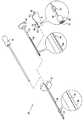
図1は、本発明の実施形態による、脈管内圧検知装置21の植え込みに使用するためのキット20を示す概略絵図である。[Detailed Description of Embodiment]
FIG. 1 is a schematic pictorial diagram illustrating a
装置21自体は、以下の図に示されるように、血管の壁を通して経皮的に挿入されるよう構成されるセンサーダイ22を具備する。センサーダイ22は、ワイヤ26によって電子機器パッケージ24に接続され、この電子機器パッケージ24は、血管の圧力を表示する出力を提供する目的で、センサーダイによって生成される電気信号を処理する。血管壁を通しての挿入を促進するために、センサーダイの横断外形寸法は、典型的には、1mm未満であるが、より大きいダイサイズおよびより小さいダイサイズもまた、技術的制約および適用要件次第で、使用されてよい。電子機器パッケージは、生体適合性材料で作成され、皮膚下への植え込みに適しており、一辺が約3〜4mmおよび高さが約0.5〜0.8mmの矩形の形態で作成されてよい。電子機器パッケージは、体外の制御ユニットによって電力供給され、反応指令信号を送信されて(interrogated)よく、この制御ユニットは、図7に示されるように、パッケージ上の皮膚に近接して設置される。 The
センサーダイ22は、いかなる適するタイプの圧力感知要素を具備してもよい。例えば、センサーダイは、圧力を受けてキャパシタンスを変形させ、要するに変更させるキャパシターを具備してよい。キャパシターは、上記に言及した米国特許第6,939,299号に記載されるように共鳴回路の一部として接続されてよく、共鳴回路のインダクターおよび他の要素が、ダイ22に、および/または、電子機器パッケージ24に備わっていてもよい。次に、センサーダイのキャパシタンスは、回路反応における共鳴ピークを検出することによって測定されてよい。代替的に、ダイ22は、ダイが遭遇する圧力に比例して電子機器パッケージ24に電圧信号を出力する圧電性の要素を具備してよい。代替的に、ダイ22は、当業分野で既知の、あらゆる他の適するタイプの圧力検知要素を具備してもよい。 The sensor die 22 may comprise any suitable type of pressure sensing element. For example, the sensor die may include a capacitor that undergoes pressure to deform and, in effect, change the capacitance. The capacitor may be connected as part of the resonant circuit as described in the above-referenced US Pat. No. 6,939,299, where the resonant circuit inductor and other elements are connected to the die 22 and / or the electronics package. 24 may be provided. The capacitance of the sensor die may then be measured by detecting a resonance peak in the circuit response. Alternatively, the
図1に示される実施形態では、ワイヤ26は、患者の身体への検知装置の配備後に張力を軽減するためのアンカー30を含む。加えて、ワイヤは、安全解放機構28によってセンサーダイ22に接続されて、センサーダイが植え込み後に血管壁から偶発的に引き抜かれるのを防いでよい。 In the embodiment shown in FIG. 1, the
検知装置21は、図1に示されるキット20の部品を使用して血管に経皮的に植え込まれ、このキット20は、
(以下に示されるようにワイヤ26を収容するための)長さ方向スロット36を備えたシャフト34を有するトロカール32と、
穿刺用具38と、
ワイヤ26のためのスロット44を備えたシャフト42をも具備する挿入具40と、
を含む。The
A
An
including.
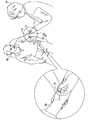
図2は、本発明の実施形態による、患者52の腕50に検知装置21を植え込むためにキット20の要素を使用している医療従事者48を示す概略絵図である。描かれた例では、従事者48は、患者の上腕動脈にセンサーダイを挿入している。この経皮的処置では、従事者は概して標的動脈を直接的には見ることができないので、この処置は、動脈を可視化するため、ならびに、神経および近くの他の構造部を偶発的に損傷することを避けるために、おそらくは超音波映像法または他の手段を使用して、局部麻酔のもとで実施されてよい。上腕動脈は経皮的アプローチによって容易にアクセス可能なので、都合がよい。代替的に、本明細書に記載される装置および方法は、他の動脈および静脈、ならびに、この種のアプローチを受けることが可能な他の器官および身体通路における圧力の測定に適用されてよい。 FIG. 2 is a schematic pictorial diagram illustrating a
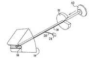
図3〜図5は、本発明の実施形態による、上腕動脈などの血管56への検知装置21の植え込みにおける連続的段階の詳細を示す概略絵図である。第一に図3に示されるように、従事者48は、患者52の皮膚54を通して、および、下層組織を通して、トロカール32の遠位端部を、血管56に達するまで、通す。次に従事者は、トロカールのシャフトを通して穿刺用具38を挿入し、穿刺用具の端部の遠位先端58を使用して血管壁に小さい穴を作成する。 3-5 are schematic pictorial diagrams showing details of successive stages in the implantation of the
次に図4に示されるように、従事者は、穿刺用具を引き出し、挿入具40を使用して、トロカール32を通して血管56の中にセンサーダイ(この図では見られない)を押し込む。ワイヤ26の近位端部は、スロット44およびスロット36を通して電子機器パッケージ24まで外に延びる(というのも、電子機器パッケージは大きすぎてトロカールシャフトの中に収まらないからである)。図5に示されるように完全に延びた状態では、センサーダイ22は、血管56の中にわずかに突出し、一方、電子機器パッケージ24は皮膚54の表面の直ぐ上に留まる。センサーダイの小さいサイズ、および、本明細書に例示される植え込みに対する経皮的なアプローチによって、血管への外傷および血液の漏出が最小化され、植え込み後の迅速な治癒が促進される。センサーダイは、血管壁の内側の側部に延びるアンカー機構(不図示)を使用して血管内部の所定の場所に固着されてよく、アンカー機構の例には、参照によってその開示内容が本明細書に組み込まれる米国特許第6,783,499号に記載されるものと同様の機構などがある。 Next, as shown in FIG. 4, the practitioner pulls the puncture tool and uses the
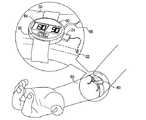
図6は、本発明の実施形態による、植え込み後の検知装置21の配備を示す概略絵図である。センサーダイ22が、図5に示されるように、血管の壁を通して挿入された後、従事者48は、皮膚54を通して挿入具40およびトロカール32を引き出す。トロカールの引き出しにより、センサーダイの近くの、ワイヤ26上のアンカー30が外方に開き、ゆえに、センサーが血管56から偶発的に引き抜かれるのを防ぐ。従事者はまた、適する切開部を通して皮膚54の表面の直ぐ下に電子機器パッケージ24を植え込んでもよい。 FIG. 6 is a schematic pictorial diagram illustrating deployment of the
図7は、本発明の実施形態による、センサーダイ22および電子機器パッケージ24と連結した、脈管内圧測定のための制御ユニット60を示す概略絵図である。例えば、制御ユニットは、図に示されるように腕50などの身体の肢部の周囲に結び付けられてよく、ゆえに、センサーダイから(電子機器パッケージを介して)圧力読取値を継続的に受信してよい。代替的に制御ユニットは、必要に応じて、断続的にのみ、腕に近接して設置されてよい。いずれの場合も、制御ユニットは、例えば誘導(induction)を使用して、ワイヤレスリンクによって、電子機器パッケージ24に電力を送り、電子機器パッケージから出力信号を受信してよい。 FIG. 7 is a schematic pictorial diagram illustrating a
図7に示される構成では、制御ユニット60のマイクロコントローラー62がワイヤレスリンクを介して電子機器パッケージ24に反応指令信号を送信し、電子機器パッケージの出力を処理して、較正された圧力読取値を導き出す。この読取値は、表示器64に提示されてよい。代替的にまたは追加的に、読取値は、制御ユニットの記憶装置に保存されてよく、および/または、ワイヤレスまたはワイヤ接続によって監視ステーション(不図示)に移送されてよい。 In the configuration shown in FIG. 7, the
別の選択肢として、制御ユニット60によって提供される継続的な圧力監視は、高血圧を制御するための他の治療または閉ループ投薬(closed-loop drug administration)を調整するために使用され得る。例えば図7に示される実施形態では、制御ユニット60は、薬貯蔵部およびポンプ(不図示)を具備し、これらは、測定された圧力に基づく服用量で、管66を通して患者の身体に薬剤を投与する。 As another option, the continuous pressure monitoring provided by the
上記に記載された実施形態は例として引用されており、かつ、本発明は本明細書において上記で特に示され説明された内容に制限されるものではないことが、認識されるだろう。それどころか、本発明の範囲は、本明細書において上記に記載された様々な特徴部のコンビネーションおよびサブコンビネーションの双方、ならびに、前述の説明を読むことで当業者が想到し、かつ、先行技術において開示されていない、それらの変形物および改変物をも含む。 It will be appreciated that the embodiments described above are cited by way of example, and that the present invention is not limited to what has been particularly shown and described hereinabove. On the contrary, the scope of the present invention has been conceived by those skilled in the art upon reading both the various feature combinations and sub-combinations described hereinabove, as well as the foregoing description, and disclosed in the prior art. Those modifications and variations that have not been included are also included.
Claims (17)
Translated fromJapanese血管の圧力に反応する電気信号を生成するために患者の血管の壁を通して経皮的に挿入されるよう構成されたセンサーダイと、
前記センサーダイに接続された第1の端部を有し、かつ、第2の端部を有する、ワイヤと、
皮下に植え込まれるよう構成される電子機器パッケージであって、前記圧力を表示する出力を提供する目的で、前記センサーダイによって生成される前記電気信号を受信および処理するために、前記ワイヤの前記第2の端部に接続されている、電子機器パッケージと、
を具備する、器具。For pressure sensing instruments,
A sensor die configured to be inserted percutaneously through the wall of a patient's blood vessel to generate an electrical signal that is responsive to blood vessel pressure;
A wire having a first end connected to the sensor die and having a second end;
An electronics package configured to be implanted subcutaneously, for receiving and processing the electrical signal generated by the sensor die for the purpose of providing an output indicative of the pressure; An electronic device package connected to the second end;
A device comprising:
前記センサーダイは、1mm以下の横断外形寸法を有する、器具。The instrument of claim 1,
The sensor die has a transverse outer dimension of 1 mm or less.
前記ワイヤに接続されたアンカーであって、前記血管からの前記センサーダイの偶発的な除去を防ぐ目的で、前記検知装置の植え込みの後に前記患者の皮膚下で開くよう構成された、アンカー、
をさらに具備する、器具。The instrument of claim 1,
An anchor connected to the wire, the anchor configured to open under the patient's skin after implantation of the sensing device for the purpose of preventing accidental removal of the sensor die from the blood vessel;
A device further comprising:
前記圧力の読取値を提供するために、ワイヤレスリンクを介して前記電子機器パッケージから前記出力を受信し、かつ、前記出力を処理するよう構成された、制御ユニット、
をさらに具備する、器具。The instrument of claim 1,
A control unit configured to receive and process the output from the electronics package via a wireless link to provide the pressure reading;
A device further comprising:
前記装置は、前記圧力の前記読取値を継続的に提供し、かつ、前記圧力に反応して前記患者に治療を自動的に施すよう構成される、器具。The instrument of claim 4,
The apparatus is configured to continually provide the reading of the pressure and to automatically treat the patient in response to the pressure.
前記患者の皮膚を通して前記血管の近傍に挿入されるトロカールと、
前記トロカールを通して挿入され、かつ、前記血管の壁を貫いて穴を作成するよう構成された穿刺用具と、
前記トロカールを介して前記穴を通して前記血管の中に前記センサーダイを挿入するために、前記穿刺用具の引き出し後に前記トロカールを通して挿入されるよう構成された挿入具と、
をさらに具備する、器具。The instrument of claim 1,
A trocar inserted near the blood vessel through the patient's skin;
A puncture device inserted through the trocar and configured to create a hole through the vessel wall;
An insertion tool configured to be inserted through the trocar after withdrawal of the puncture tool to insert the sensor die into the blood vessel through the hole through the trocar;
A device further comprising:
前記トロカールは、長さ方向スロットを有するシャフトを具備し、
前記センサーダイを前記トロカールの外側の前記電子機器パッケージに接続するために、前記ワイヤは前記スロットを通り、一方、前記センサーダイは前記トロカールの中にある、器具。The instrument of claim 6,
The trocar comprises a shaft having a longitudinal slot;
An instrument for connecting the sensor die to the electronics package outside the trocar, wherein the wire passes through the slot, while the sensor die is in the trocar.
患者の身体の解剖学的構造部の壁を通して経皮的にセンサーダイを植え込むことと、
ワイヤによって前記センサーダイに接続されている電子機器パッケージを皮下に植え込むことと、
前記解剖学的構造部の圧力を表示する出力を提供する目的で、前記センサーダイから前記ワイヤを介して受信された電気信号を前記電子機器パッケージで処理することと、
を具備する、方法。In a method for detecting pressure,
Implanting the sensor die percutaneously through the wall of the patient's body anatomy,
Implanting an electronic device package connected to the sensor die by a wire subcutaneously;
Processing an electrical signal received via the wire from the sensor die with the electronics package for the purpose of providing an output indicating the pressure of the anatomical structure;
A method comprising:
前記センサーダイは、1mm以下の横断外形寸法を有する、方法。The method of claim 8, wherein
The method wherein the sensor die has a cross-sectional dimension of 1 mm or less.
前記センサーダイを植え込むことは、前記血管からの前記センサーダイの偶発的な除去を防ぐ目的で、前記センサーダイの植え込みの後に前記患者の皮膚下で、前記ワイヤに接続されているアンカーを開くことを具備する、方法。The method of claim 8, wherein
Implanting the sensor die opens an anchor connected to the wire under the patient's skin after implantation of the sensor die for the purpose of preventing accidental removal of the sensor die from the blood vessel. A method comprising:
前記圧力の読取値を提供するために、ワイヤレスリンクを介して前記電子機器パッケージから前記出力を受信すること、および、前記出力を処理すること、
を具備する、方法。The method of claim 8, wherein
Receiving the output from the electronics package via a wireless link and processing the output to provide a reading of the pressure;
A method comprising:
前記出力を処理することは、前記圧力の前記読取値を継続的に提供することを具備し、
前記方法は、
前記圧力に反応して前記患者に治療を自動的に施すこと、
を具備する、方法。The method of claim 11, wherein
Processing the output comprises continuously providing the reading of the pressure;
The method
Automatically treating the patient in response to the pressure;
A method comprising:
前記患者の肢部に結び付けられている制御ユニットによって、前記読取値は提供され、かつ、前記治療は施される、方法。The method of claim 12, wherein
A method wherein the reading is provided and the treatment is administered by a control unit associated with the patient's limb.
前記センサーダイを植え込むことは、
前記患者の皮膚を通して前記解剖学的構造部の近傍にトロカールを挿入することと、
前記解剖学的構造部の壁を貫いて穴を作成するために、前記トロカールを通して穿刺用具を通すことと、
前記トロカールを介して前記穴を通して前記解剖学的構造部の中に前記センサーダイを挿入することと、
を具備する、方法。The method of claim 8, wherein
Implanting the sensor die
Inserting a trocar through the patient's skin in the vicinity of the anatomical structure;
Passing a puncture device through the trocar to create a hole through the wall of the anatomical structure;
Inserting the sensor die into the anatomical structure through the hole through the trocar;
A method comprising:
前記センサーダイを植え込むことは、動脈の壁を通して前記センサーダイを挿入することを具備する、方法。The method of claim 8, wherein
Implanting the sensor die comprises inserting the sensor die through an arterial wall.
前記動脈は、上腕動脈を具備する、方法。The method of claim 15, wherein
The method wherein the artery comprises a brachial artery.
前記センサーダイを挿入することは、前記センサーダイを挿入する前に、超音波映像法を使用して前記動脈を可視化することを具備する、方法。The method of claim 15, wherein
Inserting the sensor die comprises visualizing the artery using ultrasound imaging prior to inserting the sensor die.
Applications Claiming Priority (1)
| Application Number | Priority Date | Filing Date | Title |
|---|---|---|---|
| US12/211,592US20100069763A1 (en) | 2008-09-16 | 2008-09-16 | Intravascular pressure sensor |
Publications (1)
| Publication Number | Publication Date |
|---|---|
| JP2010069300Atrue JP2010069300A (en) | 2010-04-02 |
Family
ID=41278225
Family Applications (1)
| Application Number | Title | Priority Date | Filing Date |
|---|---|---|---|
| JP2009212670AWithdrawnJP2010069300A (en) | 2008-09-16 | 2009-09-15 | Intravascular pressure sensor |
Country Status (7)
| Country | Link |
|---|---|
| US (1) | US20100069763A1 (en) |
| EP (1) | EP2163192A3 (en) |
| JP (1) | JP2010069300A (en) |
| CN (1) | CN101683261B (en) |
| AU (1) | AU2009213069A1 (en) |
| CA (1) | CA2680567A1 (en) |
| IL (1) | IL200955A0 (en) |
Families Citing this family (9)
| Publication number | Priority date | Publication date | Assignee | Title |
|---|---|---|---|---|
| US9254091B2 (en) | 2010-07-28 | 2016-02-09 | Medtronic, Inc. | Measurement of cardiac cycle length and pressure metrics from pulmonary arterial pressure |
| US9314205B2 (en) | 2011-04-28 | 2016-04-19 | Medtronic, Inc. | Measurement of cardiac cycle length and pressure metrics from pulmonary arterial pressure |
| US20130109980A1 (en)* | 2011-11-01 | 2013-05-02 | Tat-Jin Teo | Systems and methods for a wireless vascular pressure measurement device |
| CN103284710A (en)* | 2013-05-21 | 2013-09-11 | 陈绍良 | Implantable recyclable pulmonary vessel pressure sensor and use method thereof |
| WO2018001389A1 (en)* | 2016-06-27 | 2018-01-04 | Dongping Lin | Implantable monitor |
| CN106361303A (en)* | 2016-08-30 | 2017-02-01 | 福州瑞芯微电子股份有限公司 | Blood vessel detection integrated chip and implementation method thereof |
| US11583193B2 (en)* | 2016-11-14 | 2023-02-21 | Philips Image Guided Therapy Corporation | Wireless intraluminal device and system |
| CN110049721B (en)* | 2016-12-07 | 2022-06-28 | 财团法人峨山社会福祉财团 | Brain pressure measuring device |
| CN112386241A (en)* | 2020-11-13 | 2021-02-23 | 深圳大学 | Implantable blood pressure meter based on NFC |
Family Cites Families (16)
| Publication number | Priority date | Publication date | Assignee | Title |
|---|---|---|---|---|
| GB8408656D0 (en)* | 1984-04-04 | 1984-05-16 | Semple C | Animal identification |
| US5113868A (en)* | 1987-06-01 | 1992-05-19 | The Regents Of The University Of Michigan | Ultraminiature pressure sensor with addressable read-out circuit |
| DE69123982T2 (en)* | 1990-11-20 | 1997-12-04 | Innerdyne Medical Inc | STRETCH MAINTENANCE GUIDE ELEMENT AND DILATATOR |
| DE69724781T2 (en)* | 1997-01-03 | 2004-07-01 | Biosense, Inc., Miami | STENT FOR MEASURING PRESSURE |
| US6024704A (en)* | 1998-04-30 | 2000-02-15 | Medtronic, Inc | Implantable medical device for sensing absolute blood pressure and barometric pressure |
| US6149600A (en)* | 1998-05-08 | 2000-11-21 | Poorman-Ketchum; Rebekah | Blood pressure measuring device |
| US6802811B1 (en)* | 1999-09-17 | 2004-10-12 | Endoluminal Therapeutics, Inc. | Sensing, interrogating, storing, telemetering and responding medical implants |
| US6939299B1 (en)* | 1999-12-13 | 2005-09-06 | Kurt Petersen | Implantable continuous intraocular pressure sensor |
| US6764446B2 (en)* | 2000-10-16 | 2004-07-20 | Remon Medical Technologies Ltd | Implantable pressure sensors and methods for making and using them |
| US6783499B2 (en)* | 2000-12-18 | 2004-08-31 | Biosense, Inc. | Anchoring mechanism for implantable telemetric medical sensor |
| US6702847B2 (en)* | 2001-06-29 | 2004-03-09 | Scimed Life Systems, Inc. | Endoluminal device with indicator member for remote detection of endoleaks and/or changes in device morphology |
| WO2004026363A2 (en)* | 2002-09-17 | 2004-04-01 | U.S. Government As Represented By The Secretary Of The Army | Needle with fiberoptic capability |
| US8303511B2 (en)* | 2002-09-26 | 2012-11-06 | Pacesetter, Inc. | Implantable pressure transducer system optimized for reduced thrombosis effect |
| US20050197585A1 (en)* | 2004-03-06 | 2005-09-08 | Transoma Medical, Inc. | Vascular blood pressure monitoring system with transdermal catheter and telemetry capability |
| US7988674B2 (en)* | 2006-10-30 | 2011-08-02 | Medtronic, Inc. | Externally releasable body portal anchors and systems |
| US8043223B2 (en)* | 2006-11-22 | 2011-10-25 | The General Electric Company | Method and apparatus for automated vascular function testing |
- 2008
- 2008-09-16USUS12/211,592patent/US20100069763A1/ennot_activeAbandoned
- 2009
- 2009-09-10EPEP09169956Apatent/EP2163192A3/ennot_activeWithdrawn
- 2009-09-11AUAU2009213069Apatent/AU2009213069A1/ennot_activeAbandoned
- 2009-09-15ILIL200955Apatent/IL200955A0/enunknown
- 2009-09-15JPJP2009212670Apatent/JP2010069300A/ennot_activeWithdrawn
- 2009-09-16CNCN2009101690770Apatent/CN101683261B/ennot_activeExpired - Fee Related
- 2009-09-16CACA2680567Apatent/CA2680567A1/ennot_activeAbandoned
Also Published As
| Publication number | Publication date |
|---|---|
| EP2163192A2 (en) | 2010-03-17 |
| CA2680567A1 (en) | 2010-03-16 |
| CN101683261B (en) | 2013-05-01 |
| IL200955A0 (en) | 2010-06-16 |
| AU2009213069A1 (en) | 2010-04-01 |
| EP2163192A3 (en) | 2010-03-24 |
| US20100069763A1 (en) | 2010-03-18 |
| CN101683261A (en) | 2010-03-31 |
Similar Documents
| Publication | Publication Date | Title |
|---|---|---|
| JP2010069300A (en) | Intravascular pressure sensor | |
| US11666746B2 (en) | Medical product comprising a functional element for the invasive use in a patient's body | |
| EP4241821B1 (en) | Cardiac implant devices with integrated pressure sensing | |
| JP2972251B2 (en) | Long-term measurement system for internal pressure | |
| US11185245B2 (en) | Catheter for monitoring pressure for muscle compartment syndrome | |
| US20220087554A1 (en) | Delivery devices, systems, and methods of use for positioning and using hemodynamic monitoring systems | |
| KR20050013980A (en) | Energy transfer amplification for intrabody devices | |
| JP2009165842A (en) | Apparatus and method for minimally invasive calibration of implanted pressure transducers | |
| CN110087534A (en) | For the hydrostatic offset adjustment of the pressure cvd value measured | |
| CN112870543B (en) | Drug release control device, control method thereof, and computer-readable storage medium | |
| US7488345B2 (en) | Endovascular graft with pressor and attachment methods | |
| CN116113354A (en) | Sensor stabilizer | |
| Hammond et al. | A wireless and battery-less miniature intracardiac pressure sensor: early implantation studies | |
| US20220000381A1 (en) | Catheter for monitoring pressure for muscle compartment syndrome | |
| US20180168839A1 (en) | Methods and devices for confirming placement of a device within a cavity | |
| TW202300091A (en) | Embedded sensor implant devices | |
| TW202304549A (en) | Sensor implant device anchoring | |
| WO2018222557A1 (en) | Catheter for monitoring pressure for muscle compartment syndrome | |
| EP4537741A1 (en) | Intravascular implant | |
| WO1993000037A1 (en) | Method and apparatus for the measurement of atrial pressure | |
| AU665747B2 (en) | Method and apparatus for the measurement of atrial pressure |
Legal Events
| Date | Code | Title | Description |
|---|---|---|---|
| RD04 | Notification of resignation of power of attorney | Free format text:JAPANESE INTERMEDIATE CODE: A7424 Effective date:20100708 | |
| RD04 | Notification of resignation of power of attorney | Free format text:JAPANESE INTERMEDIATE CODE: A7424 Effective date:20111212 | |
| A300 | Application deemed to be withdrawn because no request for examination was validly filed | Free format text:JAPANESE INTERMEDIATE CODE: A300 Effective date:20121204 |