Movatterモバイル変換


[0]ホーム

URL:


JP2010063702A - Multiple clip unit - Google Patents

Multiple clip unit
Download PDF

Info

Publication number
JP2010063702A
JP2010063702AJP2008233656AJP2008233656AJP2010063702AJP 2010063702 AJP2010063702 AJP 2010063702AJP 2008233656 AJP2008233656 AJP 2008233656AJP 2008233656 AJP2008233656 AJP 2008233656AJP 2010063702 AJP2010063702 AJP 2010063702A
Authority
JP
Japan
Prior art keywords
clip
sheath
hook
connection
unit
Prior art date
Legal status (The legal status is an assumption and is not a legal conclusion. Google has not performed a legal analysis and makes no representation as to the accuracy of the status listed.)
Abandoned
Application number
JP2008233656A
Other languages
Japanese (ja)
Inventor
Masafuku Sai
勝福 崔
Takayuki Iida
孝之 飯田
Yoshiyuki Kunuki
義幸 九貫
Current Assignee (The listed assignees may be inaccurate. Google has not performed a legal analysis and makes no representation or warranty as to the accuracy of the list.)
Fujifilm Corp
Original Assignee
Fujifilm Corp
Priority date (The priority date is an assumption and is not a legal conclusion. Google has not performed a legal analysis and makes no representation as to the accuracy of the date listed.)
Filing date
Publication date
Application filed by Fujifilm CorpfiledCriticalFujifilm Corp
Priority to JP2008233656ApriorityCriticalpatent/JP2010063702A/en
Priority to EP09006037Aprioritypatent/EP2113208A3/en
Priority to US12/434,196prioritypatent/US20090275959A1/en
Publication of JP2010063702ApublicationCriticalpatent/JP2010063702A/en
Abandonedlegal-statusCriticalCurrent

Links

Images

Landscapes

Abstract

Translated fromJapanese

【課題】シース内へ容易に装填され、且つメンテナンス性を向上させた連結クリップユニットを提供する。
【解決手段】連結クリップユニット13は、1列に連結された複数個の止血クリップ体17A〜17Cと、最後尾の止血クリップ体17Cに連結された連結用クリップ体18からなる。止血クリップ体17は、クリップ19A〜19Cと、連結リング20A〜20Cとを備えている。連結用クリップ体18は、クリップ19Cの後端に係合するダミークリップ47と、ダミークリップ47を保持する連結部材48とからなる。操作ワイヤ12の先端には、フック57が設けられている。連結部材48の後端側には、一対の弾性アーム53が設けられている。フック57は、前フック58及び後フック59からなる。弾性アーム53に前フック58を重ねて連結部材48の径方向にフック57を押圧すると連結部材48とフック57とが係合される。
【選択図】図2
A connection clip unit that is easily loaded into a sheath and has improved maintainability.
A connection clip unit 13 includes a plurality of hemostatic clip bodies 17A to 17C connected in a row and a connection clip body 18 connected to the last hemostatic clip body 17C. The hemostatic clip body 17 includes clips 19A to 19C and connecting rings 20A to 20C. The connecting clip body 18 includes a dummy clip 47 that engages with the rear end of the clip 19 </ b> C and a connecting member 48 that holds the dummy clip 47. A hook 57 is provided at the tip of the operation wire 12. A pair of elastic arms 53 are provided on the rear end side of the connecting member 48. The hook 57 includes a front hook 58 and a rear hook 59. When the front hook 58 is overlapped on the elastic arm 53 and the hook 57 is pressed in the radial direction of the connecting member 48, the connecting member 48 and the hook 57 are engaged.
[Selection] Figure 2

Description

Translated fromJapanese

本発明は、複数のクリップが連結され、生体内等で止血や傷口の閉塞等を連続して行うことができるクリップ処置具に装填される連結クリップユニットに関する。  The present invention relates to a connected clip unit that is loaded into a clip treatment instrument that is connected to a plurality of clips and can continuously perform hemostasis, wound closure, and the like in a living body.

クリップ処置具は、内視鏡の鉗子チャンネルを通じて生体内に挿入され、その先端からクリップを突出させ、出血部や病変組織を除去した部位といった患部をクリップで挟み、止血や傷口の閉塞等を行うクリップ処置に用いられる。特許文献1に記載されているように、クリップ処置具は、操作ワイヤが挿通されたシースを有しており、クリップは操作ワイヤに連結された状態でシース内に装填される。  The clip treatment tool is inserted into the living body through the forceps channel of the endoscope, the clip protrudes from the tip, the affected part such as the site where the bleeding part or the lesioned tissue has been removed is sandwiched between the clips, and hemostasis or wound closure is performed. Used for clip treatment. As described inPatent Document 1, the clip treatment tool has a sheath through which an operation wire is inserted, and the clip is loaded into the sheath while being connected to the operation wire.

特許文献1のクリップ処置具は、クリップを1つしか装填できないため、一回のクリップ処置を行うごとにクリップ処置具を内視鏡から引き出し、次のクリップを装填して再び内視鏡に挿入するという煩雑な作業が必要である。  Since only one clip can be loaded with the clip treatment tool ofPatent Document 1, the clip treatment tool is pulled out from the endoscope every time a clip treatment is performed, and the next clip is loaded and reinserted into the endoscope. It is necessary to carry out complicated work.

こうした煩雑さを解消するために、連続的なクリップ処置を可能にする連発式クリップ処置具が提案されている。例えば、特許文献2には、前方に配されたクリップの後端部分に形成された連結孔に、後方に配されたクリップの先端の爪部を係合させることにより、複数のクリップが90度ずつ交互に向きを変えて直接連結されるようにした連発式クリップ処置具が記載されている。  In order to eliminate such complications, a repetitive clip treatment tool that enables continuous clip treatment has been proposed. For example, Patent Document 2 discloses that a plurality of clips are 90 degrees by engaging a claw portion at the front end of a clip disposed rearward with a connecting hole formed in a rear end portion of a clip disposed forward. A repetitive clip treatment device is described in which the directions are alternately changed and connected directly.

特許文献2に記載されたクリップは、一枚の細長の板材を略U字状に屈曲させて形成され、先端には、板材の開放端のそれぞれに形成された一対の爪部が設けられる。クリップは、一対の爪部は板材が弾性変形することにより開閉する。爪部はシース内に装填されるとシースの内壁によって押圧されて閉じた状態となる。これにより、後方のクリップの爪部が前方のクリップの後端を挟み込むことにより、隣接するクリップ同士が係合し、シース内においては、クリップ間の安定的な連結状態が得られる。処置の際には、先頭のクリップから順番に使用される。操作ワイヤの押し込みにより、処置に使用する先頭のクリップをその後端までシース外へ送り出すと、後方のクリップの爪部が開き、係合が解除される。  The clip described in Patent Document 2 is formed by bending a single elongated plate material into a substantially U shape, and a pair of claw portions formed at each of the open ends of the plate material is provided at the tip. The pair of claws are opened and closed by elastic deformation of the plate material. When the claw portion is loaded in the sheath, it is pressed by the inner wall of the sheath to be in a closed state. Thereby, when the claw part of the rear clip sandwiches the rear end of the front clip, adjacent clips are engaged with each other, and a stable connection state between the clips is obtained in the sheath. At the time of treatment, it is used in order from the first clip. When the leading clip used for the treatment is pushed out of the sheath to the rear end by pushing the operating wire, the claw portion of the rear clip opens and the engagement is released.

操作ワイヤは、1列に連結されたクリップの最後尾のクリップと連結する。操作ワイヤの先端には、最後尾のクリップと連結するための連結部材が固定的に設けられている。連結部材は、クリップと同様の弾性を有する細長の板材で形成され、先端に開閉可能な一対の爪部を有する弾性部材を有している。そのため、クリップ同士の係合と同様に、連結部材の先端の爪部が、最後尾のクリップの後端を挟み込んで係合する。このように、連結部材と最後尾のクリップの係合方法が同じであるため、1番目のクリップから最後尾のクリップまで、係合の解除操作(操作ワイヤの押し込み)を共通にすることができ、操作性が良好である。
特開2005−021857号公報特開2006−187391号公報
The operation wire is connected to the last clip of the clips connected in one row. A connecting member for connecting to the last clip is fixedly provided at the tip of the operation wire. The connecting member is formed of an elongated plate material having elasticity similar to that of the clip, and has an elastic member having a pair of claw portions that can be opened and closed at the tip. Therefore, similarly to the engagement between the clips, the claw portion at the front end of the connecting member engages with the rear end of the rearmost clip interposed therebetween. In this way, since the engagement method of the connecting member and the last clip is the same, it is possible to share the release operation (pushing of the operation wire) from the first clip to the last clip. The operability is good.
JP 2005-021857 A JP 2006-187391 A

しかしながら、特許文献2の連発式クリップ処置具は、操作性は良好であるものの、操作ワイヤに固定された連結部材が弾性変形することによりクリップと連結する構成であるため、クリップのみを交換して操作ワイヤを繰り返し使用する場合には、連結部材の弾性変形による劣化が懸念されている。連結部材が劣化した場合、操作ワイヤごと交換しなければならず、メンテナンス性に問題がある。  However, although the continuous clip treatment tool of Patent Document 2 has good operability, the connection member fixed to the operation wire is elastically deformed so that it is connected to the clip. When the operation wire is repeatedly used, there is a concern about deterioration due to elastic deformation of the connecting member. When the connecting member deteriorates, the entire operation wire must be replaced, and there is a problem in maintainability.

本発明は、連発式クリップ処置具の良好な操作性を維持しつつ、そのメンテナンス性を向上させることが可能な連結クリップユニットを提供することを目的とする。  An object of this invention is to provide the connection clip unit which can improve the maintainability, maintaining the favorable operativity of a continuous-type clip treatment tool.

本発明の連結クリップパッケージは、前方のクリップの後端と、後方のクリップの先端に形成された1対の爪部とを係合させることにより、1列に並べて連結された複数のクリップと、各クリップと同形状の爪部を有し、爪部によって最後尾のクリップの後端と係合するダミークリップと、前記ダミークリップを保持するとともに、処置具のシースに挿通された操作ワイヤの先端に形成されたフックと着脱可能に連結される連結部材であり、弾性変形することによって前記フックを挟み込んで連結する連結部材とを備えたことを特徴とする。  The connection clip package of the present invention includes a plurality of clips connected in a line by engaging a rear end of a front clip and a pair of claw portions formed at a tip of a rear clip, A dummy clip that has a claw portion of the same shape as each clip, and engages with the rear end of the rearmost clip by the claw portion, and holds the dummy clip and the distal end of the operation wire inserted through the sheath of the treatment instrument A connecting member that is detachably connected to the hook formed on the hook, and includes a connecting member that sandwiches and connects the hook by elastic deformation.

なお、前記連結部材は、前記シースへの挿入方向に向かって先細になるように、その後端部が傾斜していることが好ましい。  In addition, it is preferable that the rear-end part of the said connection member inclines so that it may taper toward the insertion direction to the said sheath.

本発明によれば、1列に並べて連結されたクリップの後端部に係合するダミークリップを連結部材が保持し、この連結部材と、操作ワイヤの先端に形成されたフックとが着脱可能に連結されるので、連結クリップユニットがシース内へ容易に装填され、且つメンテナンス性を向上させることができる。  According to the present invention, the connecting member holds the dummy clip that engages with the rear end portion of the clips connected in a line, and the connecting member and the hook formed at the tip of the operation wire can be attached and detached. Since they are connected, the connecting clip unit can be easily loaded into the sheath, and maintainability can be improved.

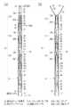
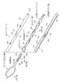
図1に示すように、連発式クリップ処置具(以下、クリップ処置具と呼ぶ)10は、円筒状のシース11と、シース11内に挿通された操作ワイヤ12と、シース11内に装填されて操作ワイヤ12に連結される連結クリップユニット13と、シース11と操作ワイヤ12との牽引操作に用いる操作部14を備えている。  As shown in FIG. 1, a repetitive clip treatment tool (hereinafter referred to as a “clip treatment tool”) 10 is loaded into acylindrical sheath 11, anoperation wire 12 inserted through thesheath 11, and thesheath 11. Aconnection clip unit 13 connected to theoperation wire 12 and an operation unit 14 used for a pulling operation of thesheath 11 and theoperation wire 12 are provided.

図2に示すように、連結クリップユニット13は、1列に連結された複数個の止血クリップ体17(17A〜17C)と、最後尾の止血クリップ体17Cに連結された連結用クリップ体18から構成されている。止血クリップ体17は、クリップ19(19A〜19C)と、クリップ19の外側に装着された筒状の連結リング20(20A〜20C)とを備えている。  As shown in FIG. 2, the connectingclip unit 13 includes a plurality of hemostatic clip bodies 17 (17A to 17C) connected in a row and a connectingclip body 18 connected to the lasthemostatic clip body 17C. It is configured. The hemostatic clip body 17 includes a clip 19 (19A to 19C) and a cylindrical connection ring 20 (20A to 20C) attached to the outside of the clip 19.

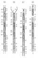
図3に示すように、クリップ19は、一枚の細長い板を180度湾曲させて閉塞端を作った後、その両片を交差させ、かつ2つの開放端が対向するように屈曲させて爪部23,23を形成している。クリップ19は、細長い板を交差させた交差部24を境にして、開放端側が腕部25,25であり、閉塞端側がターン部26である。腕部25,25の中央部分には、部分的に広幅とされた凸部27,27が形成されている。  As shown in FIG. 3, the clip 19 is formed by bending a single elongated plate 180 degrees to form a closed end, crossing the two pieces, and bending the two open ends to oppose each other.Portions 23 and 23 are formed. The clip 19 hasarm portions 25 and 25 on the open end side and aturn portion 26 on the closed end side, with acrossing portion 24 crossing the elongated plates as a boundary. Convexportions 27 and 27 that are partially wide are formed at the central portions of thearm portions 25 and 25.

腕部25,25は、外力が加えられていないときに、爪部23,23が離れた開放状態となり、互いに接近するように弾性変形したときに爪部23,23が噛合し、クリップ処置の対象となる患部を挟む閉じ状態となる。爪部23,23は、患部を確実に挟むために、V字のオス型とメス型に形成されている。クリップ19には、生体適合性のある金属を用いることができ、例えば、ばね用ステンレス鋼であるSUS631を用いることができる。  When the external force is not applied, thearm portions 25 and 25 are in an open state in which theclaw portions 23 and 23 are separated, and when thearm portions 25 and 25 are elastically deformed so as to approach each other, theclaw portions 23 and 23 mesh with each other. It will be in the closed state which pinches | interposes the affected part used as object. The nail |claw parts 23 and 23 are formed in the V-shaped male type and female type | mold in order to pinch | interpose an affected part reliably. The clip 19 can be made of a biocompatible metal, for example, SUS631 which is stainless steel for springs.

筒状部材である連結リング20は、略円筒形状であり、先端側に配された金属製の締付部30と、後端側に配されたプラスチック製の保持部31とを備えている。止血クリップ体17は、締付部30に形成された締付穴30aに、クリップ19がターン部26側から挿入され、連結リング20がクリップ19の外側に装着されることにより形成される。締付部30は、交差部24の外周を覆う初期位置にセットされ、クリップ19の腕部25,25は、開いた状態となる。  The connecting ring 20, which is a cylindrical member, has a substantially cylindrical shape, and includes ametal fastening portion 30 disposed on the front end side and aplastic holding portion 31 disposed on the rear end side. The hemostatic clip body 17 is formed by inserting the clip 19 into thetightening hole 30 a formed in the tighteningportion 30 from theturn portion 26 side and mounting the connecting ring 20 on the outside of the clip 19. The tighteningportion 30 is set at an initial position covering the outer periphery of the intersectingportion 24, and thearm portions 25, 25 of the clip 19 are in an open state.

締付穴30aは、クリップ19が連結リング20内に引き込まれたときに、腕部25,25を締め付けて爪部23,23を閉じる。爪部23,23は、腕部25,25が締め付けられることにより、所定の噛合力を発揮する。締付穴30aの径は、クリップ19の凸部27の幅よりも小さいので、クリップ19の凸部27から先は連結リング20内に挿入されない。  When the clip 19 is pulled into the connecting ring 20, the tighteninghole 30 a tightens thearm portions 25 and 25 and closes theclaw portions 23 and 23. Theclaw portions 23 and 23 exhibit a predetermined meshing force when thearm portions 25 and 25 are tightened. Since the diameter of thefastening hole 30 a is smaller than the width of theconvex portion 27 of the clip 19, the tip from theconvex portion 27 of the clip 19 is not inserted into the connecting ring 20.

図4に示すように、保持部31には、締付穴30aに連なる保持穴31aが形成されている。締付穴30aから挿入されたターン部26は、保持穴31a内に収容される。保持部31の外周面には、中心軸に対して対称に、2つのスカート部38,38が形成されている。スカート部38,38は、保持部31の先端側から後端側に向かって半径方向に広がるように形成されており、外力が加えられていないときに自身の弾性で開き、外側から押されたときに保持部31内に入り込むようにして閉じる。  As shown in FIG. 4, theholding portion 31 is formed with aholding hole 31a that is continuous with the tighteninghole 30a. Theturn part 26 inserted from the tighteninghole 30a is accommodated in theholding hole 31a. Twoskirt portions 38 are formed on the outer peripheral surface of theholding portion 31 symmetrically with respect to the central axis. Theskirt portions 38, 38 are formed so as to expand in the radial direction from the front end side to the rear end side of theholding portion 31, and are opened by their own elasticity when external force is not applied, and are pressed from the outside. Sometimes it closes so as to enter theholding part 31.

連結リング20は、爪部23,23の開閉方向と、スカート部38,38の開閉方向とが90°ずれるように、クリップ19の外側に装着される。スカート部38,38は、連結クリップユニット13がシース11内に装填されて閉じたときに、保持穴31a内に収容されているターン部26を挟み込み、連結リング20をクリップ19と一体化させる。  The connecting ring 20 is attached to the outside of the clip 19 so that the opening / closing direction of theclaw portions 23, 23 and the opening / closing direction of theskirt portions 38, 38 are shifted by 90 °. When the connectingclip unit 13 is loaded into thesheath 11 and closed, theskirt portions 38 and 38 sandwich theturn portion 26 accommodated in theholding hole 31 a and integrate the connecting ring 20 with the clip 19.

複数個の止血クリップ体17は、前方に配されているクリップ19のターン部26に後方のクリップ19の爪部23,23を係合することによって1列に連結している。連結リング20は、後方のクリップ19の爪部23,23の外側を覆い、爪部23,23が開かないようにして、クリップ19の連結を維持する。クリップ19の凸部27は、保持穴31aの径よりも大きな幅寸法を有しており、連結リング20の後方に配されたときに、その連結リング20の後端に当接する。これにより、連結リング20は、上述した初期位置から、連結クリップユニット13の後端側への移動が規制される。  The plurality of hemostatic clip bodies 17 are connected in a row by engaging theclaw portions 23 and 23 of the rear clip 19 with theturn portion 26 of the clip 19 disposed on the front side. The connection ring 20 covers the outside of theclaw portions 23 and 23 of the rear clip 19 and maintains the connection of the clip 19 so that theclaw portions 23 and 23 do not open. The projectingportion 27 of the clip 19 has a width that is greater than the diameter of theholding hole 31 a, and abuts against the rear end of the connecting ring 20 when disposed behind the connecting ring 20. Thereby, the movement of the connection ring 20 from the initial position described above to the rear end side of theconnection clip unit 13 is restricted.

連結リング20の後端部44、すなわち、スカート部38よりも後方部分には、周方向においてスカート部38,38から90°ずれた2箇所に、スリット44a,44aが形成されている。スリット44a,44aは、連結リング20の軸方向に沿って形成されており、後端部44が弾性変形してその内径が広がるようになっている。このスリット44aは、内視鏡の湾曲に合わせて連結クリップユニット13が湾曲するように、連結リング20のフレキシブル性を向上させる。また、スリット44aによって、後端部44の内径が広がるため、組立時において、2つのクリップ19の係合作業が行いやすい。  Slits 44 a and 44 a are formed at two positions that are shifted from theskirt portions 38 and 38 in the circumferential direction by 90 ° in the rear end portion 44 of the connecting ring 20, that is, the rear portion of theskirt portion 38. Theslits 44a and 44a are formed along the axial direction of the connecting ring 20, and the rear end portion 44 is elastically deformed so that the inner diameter thereof is expanded. Theslit 44a improves the flexibility of the connecting ring 20 so that the connectingclip unit 13 is bent in accordance with the bending of the endoscope. Further, since the inner diameter of the rear end portion 44 is widened by theslit 44a, it is easy to engage the two clips 19 during assembly.

保持部31には、生体適合性があり、かつ、スカート部38に要求される弾性および剛性を満たす材料が用いられる。このような保持部31の材料としては、例えば、PPSU(ポリフェニルサルホン、polyphenylsulfone)が用いられる。  A material that is biocompatible and satisfies the elasticity and rigidity required for theskirt portion 38 is used for theholding portion 31. For example, PPSU (polyphenylsulfone) is used as the material of the holdingunit 31.

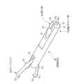
図5及び図6に示すように、連結用クリップ体18は、最後尾のクリップ19Cのターン部26に係合するダミークリップ47と、ダミークリップ47を保持する連結部材48とから構成されている。ダミークリップ47は、金属製の薄板を屈曲して形成されており、ターン部26と係合する爪部47b,47bと、連結リング20Cの後端に当接する凸部47a,47aを有している。爪部47b,47bは、クリップ19の爪部23,23と同形状に形成され、クリップ19と同様に外力が加えられていないときに自身の弾性で開き、外側から押されたときに弾性変形して閉じる。  As shown in FIGS. 5 and 6, the connectingclip body 18 includes adummy clip 47 that engages with theturn portion 26 of the rearmost clip 19 </ b> C and a connectingmember 48 that holds thedummy clip 47. . Thedummy clip 47 is formed by bending a metal thin plate, and hasclaw portions 47b and 47b that engage with theturn portion 26, andconvex portions 47a and 47a that abut on the rear end of the connectingring 20C. Yes. Theclaw portions 47b and 47b are formed in the same shape as theclaw portions 23 and 23 of the clip 19 and, like the clip 19, open by their own elasticity when external force is not applied, and elastically deform when pressed from the outside. And close.

連結部材48は、例えば、連結リング20の保持部31と同じ材質で形成された略円柱形状である。連結部材48の先端側には、ダミークリップ47を保持する切欠状の保持部51が設けられている。連結部材48の後端側には、操作ワイヤ12と連結するための係合部52が設けられている。  The connectingmember 48 has, for example, a substantially cylindrical shape formed of the same material as that of the holdingportion 31 of the connecting ring 20. A notch-shaped holdingportion 51 that holds thedummy clip 47 is provided on the distal end side of the connectingmember 48. On the rear end side of the connectingmember 48, an engagingportion 52 for connecting to theoperation wire 12 is provided.

係合部52は、連結部材48の半径方向において弾性自在にされた一対の弾性アーム53,53と、弾性アーム53,53の先端にそれぞれ設けられた挟持部54,54とを有している。一対の挟持部54,54の隙間は、操作ワイヤ12の外径よりも細くされている。また、一対の挟持部54,54には、連結部材48の中心軸に沿って、操作ワイヤ12の外径と同径の半円形の溝54a,54aが形成されている。  The engagingpart 52 has a pair ofelastic arms 53, 53 that are made elastic in the radial direction of the connectingmember 48, and clampingparts 54, 54 provided at the ends of theelastic arms 53, 53, respectively. . The gap between the pair of sandwichingportions 54, 54 is made thinner than the outer diameter of theoperation wire 12. In addition,semi-circular grooves 54 a and 54 a having the same diameter as the outer diameter of theoperation wire 12 are formed in the pair of sandwichingportions 54 and 54 along the central axis of the connectingmember 48.

挟持部54,54は、シース11への挿入方向に向かって先細になるように、外周面から後端面に掛けての外周側縁に傾斜面55が形成されている。よって、連結部材48は、後端の外径が最も小さくなっているため、シース11へ挿入を容易に行うことができる。  The sandwichingportions 54, 54 are formed with aninclined surface 55 on the outer peripheral side edge from the outer peripheral surface to the rear end surface so as to taper in the insertion direction into thesheath 11. Therefore, since the connectingmember 48 has the smallest outer diameter at the rear end, the connectingmember 48 can be easily inserted into thesheath 11.

シース11は、例えば、金属ワイヤを密着巻きした可撓性のコイルシースである。シース11の内径は、先のクリップ19のターン部26と、次のクリップ19の爪部23,23との係合が解除される寸法である。すなわち、シース11の内径は、2つの爪部23,23の長さと、ターン部26の爪部23,23が係合する部分の幅とを足し合わせた長さよりも大きい。  Thesheath 11 is, for example, a flexible coil sheath in which a metal wire is tightly wound. The inner diameter of thesheath 11 is a dimension in which the engagement between theturn portion 26 of the previous clip 19 and theclaws 23 and 23 of the next clip 19 is released. That is, the inner diameter of thesheath 11 is larger than the length obtained by adding the lengths of the twoclaw portions 23 and 23 and the width of the portion where theclaw portions 23 and 23 of theturn portion 26 are engaged.

操作ワイヤ12は、生体適合性を有する金属で形成された金属ワイヤである。図6に示すように、操作ワイヤ12の先端には、連結用クリップ体18との連結に用いられるフック57が設けられている。フック57は、操作ワイヤ12の先端に取り付けられた前フック58と、後フック59とを備えている。  Theoperation wire 12 is a metal wire formed of a metal having biocompatibility. As shown in FIG. 6, a hook 57 used for connection with theconnection clip body 18 is provided at the distal end of theoperation wire 12. The hook 57 includes afront hook 58 attached to the tip of theoperation wire 12 and arear hook 59.

前フック58は、弾性アーム53,53の間の隙間と同じ長さの1辺を有する正方形状の四角柱部58aと、弾性アーム53,53の隙間に合せた四角錐部58bと有している。後フック59は、前フック58の外径よりも大きく、連結部材48の外径よりもわずかに小さな外径を有する円柱形状である。後フック59は、前フック58の後端から所定距離だけ離れた後方に配されている。この所定距離とは、挟持部54の軸方向の長さと同じ長さである。  Thefront hook 58 has a squarecolumnar part 58 a having a side with the same length as the gap between theelastic arms 53 and 53, and aquadrangular pyramid part 58 b that matches the gap between theelastic arms 53 and 53. Yes. Therear hook 59 has a cylindrical shape having an outer diameter that is larger than the outer diameter of thefront hook 58 and slightly smaller than the outer diameter of the connectingmember 48. Therear hook 59 is disposed behind the rear end of thefront hook 58 by a predetermined distance. This predetermined distance is the same length as the axial length of the clampingpart 54.

前フック58は、係合部52の軸方向に沿って重ねられ、連結部材48の径方向に押圧されて弾性アーム53,53の間に押し込まれる。前フック58が押し込まれた弾性アーム53,53は、弾性変形することによって前フック58を挟み込んで連結する。また前フック58は、各弾性アーム53の端部に形成された一対の挟持部54と当接する。前フック58と、円柱形状の後フック59との間の操作ワイヤ12は、挟持部54により挟持される。後フック59は、挟持部54の後端に当接する。これにより、操作ワイヤ12の牽引と回転とを連結クリップユニット13に伝達し、シース11の牽引時に生じる摩擦力によって連結クリップユニット13がシース11と一緒に動かないように押さえることができる。  Thefront hook 58 is overlapped along the axial direction of the engagingportion 52, is pressed in the radial direction of the connectingmember 48, and is pushed between theelastic arms 53 and 53. Theelastic arms 53 and 53 into which thefront hook 58 is pushed are elastically deformed so as to sandwich and connect thefront hook 58. Further, thefront hook 58 comes into contact with a pair of sandwichingportions 54 formed at the end portions of theelastic arms 53. Theoperation wire 12 between thefront hook 58 and the columnarrear hook 59 is clamped by the clampingunit 54. Therear hook 59 abuts on the rear end of the holdingportion 54. Accordingly, the pulling and rotation of theoperation wire 12 can be transmitted to the connectingclip unit 13, and the connectingclip unit 13 can be pressed so as not to move together with thesheath 11 by the frictional force generated when thesheath 11 is pulled.

また、連結クリップユニット13の使用後は、シース11から操作ワイヤ12とともに引き出され、フック57を連結部材48に対して径方向に引っ張ることにより前フック58が弾性アーム53,53の間から離脱して連結部材48とフック57との係合が解除される。  Further, after theconnection clip unit 13 is used, it is pulled out together with theoperation wire 12 from thesheath 11, and thefront hook 58 is detached from between theelastic arms 53, 53 by pulling the hook 57 radially with respect to theconnection member 48. Thus, the engagement between the connectingmember 48 and the hook 57 is released.

図1に示すように、操作部14は、シース11と操作ワイヤ12とをそれぞれ牽引するシース操作ハンドル63と、ワイヤ操作ハンドル62とを有している。シース操作ハンドル63は、略円筒形状であり、先端にシース11の後端が固定されている。シース操作ハンドル63は、ワイヤ操作ハンドル62の先端に設けられたパイプ64の外側にスライド自在に装着されており、パイプ64に沿ってワイヤ操作ハンドル62側にスライドすることにより、シース11が操作ワイヤ12に対して後端側に牽引される。符合69は、シース11が操作ワイヤ12に対して後退するときに、その後退量を術者に対して触知させるためのノッチである。ノッチ69の間隔は、連結クリップユニット13のクリップ19を、1つずつシース11から押し出すための後退量に対応して設定されている。  As shown in FIG. 1, the operation unit 14 includes a sheath operation handle 63 that pulls thesheath 11 and theoperation wire 12, and a wire operation handle 62. The sheath operation handle 63 has a substantially cylindrical shape, and the rear end of thesheath 11 is fixed to the tip. The sheath operation handle 63 is slidably attached to the outside of apipe 64 provided at the tip of the wire operation handle 62. By sliding along thepipe 64 toward the wire operation handle 62, thesheath 11 is operated by the operation wire. 12 is pulled to the rear end side.Reference numeral 69 is a notch for allowing the operator to feel the amount of retraction when thesheath 11 is retreated with respect to theoperation wire 12. The interval between thenotches 69 is set corresponding to the retraction amount for pushing out the clips 19 of the connectingclip unit 13 from thesheath 11 one by one.

ワイヤ操作ハンドル62は、略円筒形状であり、スライド自在な操作レバー66を内蔵した貫通窓65を有している。操作ワイヤ12は、シース操作ハンドル63内を通って、操作レバー66に後端が係止されている。操作レバー66をスライドすると、連結リング20によるクリップ19の締め付けに必要な量だけ、操作ワイヤ12がシース11に対して牽引される。  The wire operation handle 62 has a substantially cylindrical shape and has a throughwindow 65 with aslidable operation lever 66 built therein. Theoperation wire 12 passes through the sheath operation handle 63, and the rear end is locked to theoperation lever 66. When theoperation lever 66 is slid, theoperation wire 12 is pulled with respect to thesheath 11 by an amount necessary for tightening the clip 19 by the connecting ring 20.

次に、クリップ処置具10の作用について、簡単に説明する。図7(A)に示すように、連結クリップユニット13は、先頭のクリップ19Aの先端がシース11の先端に一致するようにシース11内に装填されている。シース11は、生体内に挿入された内視鏡の鉗子チャンネルに挿入される。シース11の先端は、内視鏡先端の鉗子出口から突出して患部に近付けられる。  Next, the operation of theclip treatment tool 10 will be briefly described. As shown in FIG. 7A, the connectingclip unit 13 is loaded in thesheath 11 so that the tip of the leading clip 19 </ b> A coincides with the tip of thesheath 11. Thesheath 11 is inserted into a forceps channel of an endoscope inserted in the living body. The distal end of thesheath 11 protrudes from the forceps exit at the distal end of the endoscope and approaches the affected part.

シース操作ハンドル63を所定量だけ牽引すると、シース11が操作ワイヤ12に対して、所定量だけ後退する。操作ワイヤ12と連結クリップユニット13は連結されているので、連結クリップユニット13がシース11に対して前進し、図7(B)に示すように、シース11の先端から、先頭のクリップ19Aと連結リング20Aとが送り出される。  When the sheath operation handle 63 is pulled by a predetermined amount, thesheath 11 is retracted by a predetermined amount with respect to theoperation wire 12. Since theoperation wire 12 and theconnection clip unit 13 are connected, theconnection clip unit 13 moves forward with respect to thesheath 11 and, as shown in FIG. 7B, is connected to the leadingclip 19A from the distal end of thesheath 11. Thering 20A is sent out.

この際に、シース11の内壁面と接触している連結リング20A〜20Cに対しては、シース11との間に生じる摩擦力によって、シース11とともに後端側へ移動する力が働く。しかし、連結リング20A〜20Cは、閉じたスカート部38,38によってクリップ19A〜19Cと一体化されており、また、後方のクリップ19B,19Cの凸部27と、ダミークリップ47の凸部47aとにより後端側への移動が規制されている。このため、連結リング20A〜20Cが後退することはなく、クリップ19A〜19Cとともにシース11に対して前進する。  At this time, a force that moves to the rear end side together with thesheath 11 acts on the coupling rings 20 </ b> A to 20 </ b> C that are in contact with the inner wall surface of thesheath 11 due to a frictional force generated between thesheath 11 and the coupling rings 20 </ b> A to 20 </ b> C. However, the connectingrings 20A to 20C are integrated with theclips 19A to 19C by theclosed skirt portions 38 and 38, and theconvex portions 27 of therear clips 19B and 19C and theconvex portion 47a of thedummy clip 47 The movement to the rear end side is restricted by the above. For this reason, the connection rings 20A to 20C do not move backward, but move forward with respect to thesheath 11 together with theclips 19A to 19C.

シース11から出たクリップ19Aは、自身の弾性による爪部23,23を開く(図2(B)に示す状態)、また、図2(A)に示すように、連結リング20Aは、スカート部38,38がシース11の内径よりも広幅に開き、連結リング20Aがシース11内に戻らないように係合する。  Theclip 19A coming out of thesheath 11 opens theclaw portions 23 and 23 due to its own elasticity (the state shown in FIG. 2 (B)), and as shown in FIG. 2 (A), the connectingring 20A has a skirt portion. 38 and 38 are opened wider than the inner diameter of thesheath 11, and the connecting ring 20 </ b> A is engaged so as not to return into thesheath 11.

クリップ処置具10を移動させて、開放状態にあるクリップ19Aの爪部23,23を患部に押し付ける。この状態で、ワイヤ操作ハンドル62の操作レバー66を引くと、操作ワイヤ12が所定量だけ引っ張られ、連結用クリップ体18から順に係合している全クリップ19A〜19Cが、一様に引っ張られる。  Theclip treatment tool 10 is moved, and theclaws 23 and 23 of theclip 19A in the open state are pressed against the affected part. In this state, when theoperation lever 66 of the wire operation handle 62 is pulled, theoperation wire 12 is pulled by a predetermined amount, and all the clips 19 </ b> A to 19 </ b> C sequentially engaged from the connectingclip body 18 are pulled uniformly. .

図7(C)に示すように、シース11から送りだされたクリップ19Aは、連結リング20Aのスカート部38,38が開いているので、スカート部38,38による押圧保持が解除されている。また、連結リング20Aは、スカート部38,38によりシース11内への後退が阻止されている。そのため、先頭のクリップ19Aは、操作ワイヤ12が引かれることにより、連結リング20Aに対して後退する。締付部30がクリップ19Aの凸部27の直下まで押し込まれることにより、連結リング20Aによるクリップ19Aの締め付けが完了する。  As shown in FIG. 7C, theclip 19A fed from thesheath 11 is released from the press and hold by theskirt portions 38, 38 because theskirt portions 38, 38 of the connectingring 20A are open. Further, the connecting ring 20 </ b> A is prevented from retreating into thesheath 11 by theskirt portions 38, 38. Therefore, the leadingclip 19A moves backward with respect to the connectingring 20A when theoperation wire 12 is pulled. When the tighteningportion 30 is pushed to just below theconvex portion 27 of theclip 19A, the tightening of theclip 19A by the connectingring 20A is completed.

クリップ19Aの締め付け完了と同時に、クリップ19Aと次のクリップ19Bの係合部が連結リング20Aの後端から抜け出る。クリップ19Bの腕部25,25は、自身の弾性力によってシース11の内壁に当たるまで拡開し、爪部23,23の間がクリップ19Aのターン部26の幅よりも広く開いて、クリップ19Aとクリップ19Bとの連結が解除される。図7(D)に示すように、シース11の先端を患部から離すと、止血クリップ体17Aがシース11の先端から抜け出る。  Simultaneously with the completion of the fastening of theclip 19A, the engaging portion of theclip 19A and thenext clip 19B comes out from the rear end of the connectingring 20A. Thearm portions 25, 25 of theclip 19B are expanded by their own elastic force until they hit the inner wall of thesheath 11, and the gap between theclaw portions 23, 23 opens wider than the width of theturn portion 26 of theclip 19A. The connection with theclip 19B is released. As shown in FIG. 7D, when the distal end of thesheath 11 is separated from the affected part, the hemostatic clip body 17 </ b> A comes out from the distal end of thesheath 11.

操作レバー66の牽引操作をやめると、操作レバー66は図示しないバネの付勢力によって元の位置に復帰する。これにともない、操作ワイヤ12がシース11内で先端側に移動し、連結用クリップ体18、クリップ19B,19Cが押されるので、図7(D)に示すように、2発目のクリップ19Bの先端は、シース11の先端にほぼ一致する位置に移動する。以降、1発目の止血クリップ体17Aと同様に、操作部14を操作して、2発目、3発目の止血クリップ体17B,17Cでクリップ処置を行うことができる。上述したように、ダミークリップ47が、クリップ19A〜19Cの爪部23,23と同形状の爪部47b,47bを有することから、1,2発目のクリップ19A,19Bのターン部26と係合する爪部23,23と同様に、3発目のクリップ19Cのターン部26に爪部47b,47bが係合している。よって、1〜3発目の止血クリップ体17A〜17Cの全てが、操作部14を同様に操作することによって同じ作用、すなわち止血、シース11内の移動、離脱などの各動作を得ることができる。  When the pulling operation of theoperation lever 66 is stopped, theoperation lever 66 returns to the original position by a biasing force of a spring (not shown). Accordingly, theoperation wire 12 moves to the distal end side in thesheath 11 and the connectingclip body 18 and theclips 19B and 19C are pushed. Therefore, as shown in FIG. The distal end moves to a position that substantially coincides with the distal end of thesheath 11. Thereafter, similarly to the firsthemostatic clip body 17A, the operation unit 14 can be operated to perform the clip treatment with the second and thirdhemostatic clip bodies 17B and 17C. As described above, since thedummy clip 47 has theclaw portions 47b and 47b having the same shape as theclaw portions 23 and 23 of theclips 19A to 19C, thedummy clip 47 is associated with theturn portion 26 of the first andsecond clips 19A and 19B. Similarly to theclaw portions 23 and 23 to be joined, theclaw portions 47b and 47b are engaged with theturn portion 26 of thethird clip 19C. Therefore, all of the first to thirdhemostatic clip bodies 17A to 17C can obtain the same operation, that is, each operation such as hemostasis, movement in thesheath 11 and removal by operating the operation unit 14 in the same manner. .

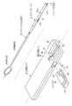
次に、連結クリップパッケージ80について説明する。図8〜10に示すように、連結クリップパッケージ80は、連結クリップユニット13を収容した円筒形状のクリップケース81と、クリップケース81の先端が挿入された長方形状の装填治具82とを備えている。装填治具82には、クリップケース81から装填治具82内に連結クリップユニット13を引き込むクリップ引込み部材83と、操作ワイヤ12と連結用クリップ体18との連結に用いられるスライダ84とが組み込まれている。  Next, theconnection clip package 80 will be described. As shown in FIGS. 8 to 10, theconnection clip package 80 includes acylindrical clip case 81 that houses theconnection clip unit 13, and arectangular loading jig 82 into which the tip of theclip case 81 is inserted. Yes. Theloading jig 82 incorporates aclip retracting member 83 that pulls thecoupling clip unit 13 from theclip case 81 into theloading jig 82, and aslider 84 that is used to couple theoperation wire 12 and thecoupling clip body 18. ing.

クリップケース81は、内側に円柱状の空間であるクリップ収容部87が設けられている。クリップケース81の外径、及びクリップ収容部87の内径は、シース11の外径及び内径とほぼ同じである。クリップ収容部87内には、先頭のクリップ19Aがクリップケース81の先端側に配されるように連結クリップユニット13が収容されている。  Theclip case 81 is provided with aclip accommodating portion 87 which is a cylindrical space on the inner side. The outer diameter of theclip case 81 and the inner diameter of theclip housing portion 87 are substantially the same as the outer diameter and inner diameter of thesheath 11. In theclip accommodating portion 87, the connectingclip unit 13 is accommodated so that the leadingclip 19A is arranged on the distal end side of theclip case 81.

装填治具82は、クリップケース81から引き込まれた連結クリップユニット13の各スカート部38を閉じ、シース11内に連結クリップユニット13を装填するための治具である。装填治具82の長手方向の一端部側には、高さ方向で凹まされた凹部90が形成されている。凹部90内には、クリップケース81の外径よりもわずかに大きな内径を有し、上部が開放されたケース挿入溝91が形成されている。凹部90内の側面には、ケース挿入溝91に連なるように、同径のケース挿入穴92が形成されている。  Theloading jig 82 is a jig for closing theskirt portions 38 of thecoupling clip unit 13 drawn from theclip case 81 and loading thecoupling clip unit 13 into thesheath 11. Arecess 90 that is recessed in the height direction is formed on one end side in the longitudinal direction of theloading jig 82. In therecess 90, acase insertion groove 91 having an inner diameter slightly larger than the outer diameter of theclip case 81 and having an open upper portion is formed. Acase insertion hole 92 having the same diameter is formed on the side surface in therecess 90 so as to be continuous with thecase insertion groove 91.

ケース挿入溝91及びケース挿入穴92には、クリップケース81が挿入されている。また、装填治具82からシース11に連結クリップユニット13を装填する際には、ケース挿入溝91及びケース挿入穴92からクリップケース81が抜き取られ、代わりにシース11が挿入される。ケース挿入溝91内に挿入されたクリップケース81、あるいはシース11は、その上部が一部露呈される。したがって、凹部90内を把持することにより、クリップケース81と装填治具82、あるいはシース11と装填治具82を一緒に保持することができる。  Aclip case 81 is inserted into thecase insertion groove 91 and thecase insertion hole 92. When the connectingclip unit 13 is loaded from theloading jig 82 to thesheath 11, theclip case 81 is extracted from thecase insertion groove 91 and thecase insertion hole 92, and thesheath 11 is inserted instead. The upper part of theclip case 81 or thesheath 11 inserted into thecase insertion groove 91 is partially exposed. Therefore, theclip case 81 and theloading jig 82 or thesheath 11 and theloading jig 82 can be held together by gripping the inside of therecess 90.

装填治具82の上面には、凹部90に隣接して連結用開口95と、ワイヤ用スリット96とが設けられている。連結用開口95は、操作ワイヤ12のフック57をクリップケース81の挿入方向と直交する横方向から装填治具82内に挿入するための開口であり、フック57を横から見たときの外径寸法よりも大きな開口面積を有している。ワイヤ用スリット96は、ケース挿入穴92と連結用開口95とを接続するように形成されており、操作ワイヤ12が横から挿入可能な幅寸法を有している。操作ワイヤ12及びフック57は、シース11がケース挿入溝91に挿入されたときに、同時にワイヤ用スリット96及び連結用開口95に挿入され、装填治具82内に引き込まれた連結用クリップ体18の連結部材48に連結される(図5参照)。  On the upper surface of theloading jig 82, aconnection opening 95 and a wire slit 96 are provided adjacent to therecess 90. Theconnection opening 95 is an opening for inserting the hook 57 of theoperation wire 12 into theloading jig 82 from the lateral direction perpendicular to the insertion direction of theclip case 81, and the outer diameter when the hook 57 is viewed from the side. The opening area is larger than the dimension. The wire slit 96 is formed so as to connect thecase insertion hole 92 and theconnection opening 95, and has a width dimension in which theoperation wire 12 can be inserted from the side. Theoperation wire 12 and the hook 57 are inserted into the wire slit 96 and theconnection opening 95 at the same time when thesheath 11 is inserted into thecase insertion groove 91, and are drawn into theloading jig 82. To the connecting member 48 (see FIG. 5).

装填治具82内には、ケース挿入穴92の奥に、円柱状の空間であるスカート閉じ通路97が設けられている。スカート閉じ通路97は、シース11及びクリップ収容部87と同じ内径を有しており、その内径面がケース挿入穴92に挿入されたクリップケース81及びシース11の内径面と連接する。スカート閉じ通路97は、クリップ収容部87から引き込まれた連結クリップユニット13の各スカート部38を内径面によって押して閉じる。  Askirt closing passage 97 that is a cylindrical space is provided in theloading jig 82 at the back of thecase insertion hole 92. Theskirt closing passage 97 has the same inner diameter as thesheath 11 and theclip accommodating portion 87, and the inner diameter surface thereof is connected to the inner diameter surface of theclip case 81 and thesheath 11 inserted into thecase insertion hole 92. Theskirt closing passage 97 closes eachskirt portion 38 of theconnection clip unit 13 drawn from theclip accommodating portion 87 by pushing the inner diameter surface.

クリップ引込み部材83は、装填治具82の長手方向の他端部側から外に突出された略楕円形の牽引部98と、牽引部98が一端に設けられた挿通部99と、挿通部99の他端に設けられた係合部100(図10も参照)とを備えている。挿通部99は、スカート閉じ通路97を貫通する長さを有した棒状体であり、スカート閉じ通路97に挿通される。係合部100は、クリップ収容部87に挿入され、先頭のクリップ19Aと係合している。  Theclip retracting member 83 includes a substantially elliptical traction portion 98 protruding outward from the other end side in the longitudinal direction of theloading jig 82, aninsertion portion 99 provided with the traction portion 98 at one end, and theinsertion portion 99. And an engaging portion 100 (see also FIG. 10) provided at the other end. Theinsertion part 99 is a rod-like body having a length penetrating theskirt closing passage 97 and is inserted into theskirt closing passage 97. The engagingportion 100 is inserted into theclip accommodating portion 87 and is engaged with the leadingclip 19A.

クリップ引込み部材83は、牽引部98の環を潰すように弾性変形させ、クリップケース81とともにケース挿入穴92に挿入される。挿通部99は、スカート閉じ通路97に挿入され、牽引部98は、スカート閉じ通路97の端部に形成された牽引穴(図11〜13の符号103参照)を通して装填治具82の外に突出される。連結クリップユニット13は、牽引部98が装填治具82に対して牽引されたときに、係合部100により先頭のクリップ19Aが引っ張られ、クリップ収容部87からスカート閉じ通路97内に引き込まれる。  Theclip retracting member 83 is elastically deformed so as to crush the ring of the pulling portion 98 and is inserted into thecase insertion hole 92 together with theclip case 81. Theinsertion portion 99 is inserted into theskirt closing passage 97, and the pulling portion 98 protrudes out of theloading jig 82 through a pulling hole (seereference numeral 103 in FIGS. 11 to 13) formed at the end of theskirt closing passage 97. Is done. When the pulling portion 98 is pulled with respect to theloading jig 82, the leading clip 19 </ b> A is pulled by the engagingportion 100 and theconnected clip unit 13 is drawn from theclip accommodating portion 87 into theskirt closing passage 97.

スライダ84は、装填治具82の側面に貫通するように設けられたスライダ通路101内に、スライド自在に挿入されている。スライダ84は、装填治具82内に引き込まれた連結用クリップ体18と、連結用開口95から挿入されたフック57とを連結させる際に、スライダ通路101内に押し込まれる。  Theslider 84 is slidably inserted into aslider passage 101 provided so as to penetrate the side surface of theloading jig 82. Theslider 84 is pushed into theslider passage 101 when the connectingclip body 18 drawn into theloading jig 82 and the hook 57 inserted from the connectingopening 95 are connected.

ケース挿入溝91の底部には、位置決め溝102が形成されている。クリップケース81が軸方向からケース挿入溝91及びケース挿入穴92に挿入されたときに、クリップケース81の下面に設けられた位置決め部116が挿入される位置決め溝102が軸方向に沿って設けられている。位置決め部116及び位置決め溝102は、連結クリップユニット13が装填治具82に対して所定の回転位置でセットされるように、装填治具82に対するクリップケース81の挿入姿勢を位置決めする。  Apositioning groove 102 is formed at the bottom of thecase insertion groove 91. When theclip case 81 is inserted into thecase insertion groove 91 and thecase insertion hole 92 from the axial direction, thepositioning groove 102 into which thepositioning portion 116 provided on the lower surface of theclip case 81 is inserted is provided along the axial direction. ing. Thepositioning portion 116 and thepositioning groove 102 position the insertion posture of theclip case 81 with respect to theloading jig 82 so that the connectingclip unit 13 is set at a predetermined rotational position with respect to theloading jig 82.

位置決め部116は、クリップケース81の軸方向のほぼ中央と後端にそれぞれ設けられている。中央に配置された位置決め部116は、クリップケース81の先端がケース挿入穴92の奥まで挿入されたときに、位置決め溝102の終端に突き当たり、装填治具82に対するクリップケース81の軸方向の位置決めを行う。  The positioningportions 116 are provided at substantially the center and the rear end of theclip case 81 in the axial direction. Thepositioning portion 116 disposed in the center hits the end of thepositioning groove 102 when the tip of theclip case 81 is inserted to the back of thecase insertion hole 92, and positions theclip case 81 in the axial direction with respect to theloading jig 82. I do.

スライダ通路101は、ケース挿入溝91と直交する方向に形成されている。スライダ通路101は、スライダ84の幅寸法とほぼ等しい幅を有する矩形状であり、装填治具82の短手方向を貫通するように設けられている。装填治具82は、連結クリップユニット13、クリップケース81、クリップ引込み部材83、スライダ84等が外側から視認できるように、例えば、透明なプラスチックで形成されている。  Theslider passage 101 is formed in a direction orthogonal to thecase insertion groove 91. Theslider passage 101 has a rectangular shape having a width substantially equal to the width dimension of theslider 84 and is provided so as to penetrate the short direction of theloading jig 82. Theloading jig 82 is made of, for example, transparent plastic so that the connectingclip unit 13, theclip case 81, theclip retracting member 83, theslider 84, and the like can be seen from the outside.

クリップ引込み部材83の挿通部99は、ケース挿入溝91の反対側に位置する牽引穴103(図12〜14参照)に挿通される。図11に示すように、挿通部99の係合部100側の端部には、側面を貫通するようにスリット99aが設けられている。スリット99aの上下には、牽引部98から係合部100に向かって広がる逆止突起99bが設けられている。逆止突起99bは、挿通部99がスリット99a部分で弾性変形することにより、牽引穴103から装填治具82の外に飛び出る。逆止突起99bは、挿通部99が再びスカート閉じ通路97内に戻らないように、挿通部99を係止する。  Theinsertion portion 99 of theclip retracting member 83 is inserted into the pulling hole 103 (see FIGS. 12 to 14) located on the opposite side of thecase insertion groove 91. As shown in FIG. 11, aslit 99a is provided at the end of theinsertion portion 99 on the engagingportion 100 side so as to penetrate the side surface. On the top and bottom of theslit 99a, checkprotrusions 99b extending from the pulling portion 98 toward the engagingportion 100 are provided. Thecheck protrusion 99b jumps out of theloading jig 82 from the pullinghole 103 when theinsertion portion 99 is elastically deformed at theslit 99a portion. Thecheck protrusion 99b locks theinsertion portion 99 so that theinsertion portion 99 does not return into theskirt closing passage 97 again.

係合部100は、連結リング20と同じ外径を有し、上下方向に配された一対のガイド片100a,100aを有している。ガイド片100a,100aの間には、ガイド片100a,100aの間隔を保つリブ100bが一体に設けられている。リブ100bの両側面には、挿通部99寄りの位置に、左右方向に突出した係合片100c、100cが一体に形成されている。  Theengaging part 100 has a pair ofguide pieces 100a, 100a that have the same outer diameter as the connection ring 20 and are arranged in the vertical direction. Arib 100b that keeps the distance between theguide pieces 100a and 100a is integrally provided between theguide pieces 100a and 100a.Engagement pieces 100c and 100c protruding in the left-right direction are integrally formed on both side surfaces of therib 100b at positions close to theinsertion portion 99.

係合部100は、連結クリップユニット13とともにクリップケース81のクリップ収容部87に収容されている。先頭のクリップ19Aは、クリップ収容部87に押されて閉じ状態となり、爪部23,23を係合片100c、100cに係合している。牽引部98を装填治具82に対して牽引すると、挿通部99は、スカート閉じ通路97内を移動し、係合部100がクリップ収容部87からスカート閉じ通路97内に移動する。  Theengaging part 100 is accommodated in theclip accommodating part 87 of theclip case 81 together with the connectingclip unit 13. The leadingclip 19A is pushed into the closed state by theclip accommodating portion 87, and engages theclaw portions 23 and 23 with the engagingpieces 100c and 100c. When the pulling portion 98 is pulled with respect to theloading jig 82, theinsertion portion 99 moves in theskirt closing passage 97, and the engagingportion 100 moves from theclip accommodating portion 87 into theskirt closing passage 97.

連結クリップユニット13は、係合部100に引っ張られてスカート閉じ通路97内に引き込まれる。スカート閉じ通路97の牽引穴103近傍には、左右方向に張り出した解除溝104(図12〜14参照)が形成されている。解除溝104の左右方向は、先頭のクリップ19Aの腕部25,25が、クリップ引込み部材83の係合部100との係合を解除する程度まで開くことができる幅寸法を有している。解除溝104は、連結用クリップ体18の係合部52が、連結用開口95に対面する位置に到達したときに、先頭のクリップ19Aが解除溝104内に到達するように配置されている。  The connectingclip unit 13 is pulled by the engagingportion 100 and pulled into theskirt closing passage 97. In the vicinity of the pullinghole 103 of theskirt closing passage 97, a release groove 104 (see FIGS. 12 to 14) protruding in the left-right direction is formed. Therelease groove 104 has a width dimension that allows thearms 25 and 25 of the leading clip 19 </ b> A to open to the extent that the engagement with theengagement portion 100 of theclip retracting member 83 is released. Therelease groove 104 is arranged so that the leading clip 19 </ b> A reaches therelease groove 104 when the engagingportion 52 of theconnection clip body 18 reaches a position facing theconnection opening 95.

先頭のクリップ19Aは、解除溝104内に到達すると自身の弾性によって開放状態に変位し、係合部100との係合を解除する。これにより、連結クリップユニット13は、連結用クリップ体18の係合部52が、ケース挿入穴92内でスライダ通路101に位置するように、スカート閉じ通路97内で停止される。  When the leading clip 19 </ b> A reaches therelease groove 104, the top clip 19 </ b> A is displaced into an open state by its own elasticity, and releases the engagement with theengagement portion 100. Thereby, the connectingclip unit 13 is stopped in theskirt closing passage 97 so that the engagingportion 52 of the connectingclip body 18 is positioned in theslider passage 101 in thecase insertion hole 92.

なお、止血クリップ体17は、爪部23,23の開閉方向と、スカート部38,38の開閉方向とが90°ずれているので、先頭のクリップ19Aが解除溝104内にあるときでも、先頭の連結リング20Aのスカート部38,38が開くことはない。  In addition, since the opening and closing direction of theclaw portions 23 and 23 and the opening and closing direction of theskirt portions 38 and 38 are shifted by 90 °, the hemostatic clip body 17 has a leading end even when the leadingclip 19A is in therelease groove 104. Theskirt portions 38, 38 of the connectingring 20A are not opened.

クリップ引込み部材83を構成する牽引部98、挿通部99、係合部100は、例えば、適度な弾性を有するプラスチックによって一体に形成されている。なお、挿通部99と係合部100とを別体で形成し、装填治具82内で連結させてもよい。  The pulling portion 98, theinsertion portion 99, and the engagingportion 100 constituting theclip retracting member 83 are integrally formed of, for example, plastic having appropriate elasticity. Note that theinsertion portion 99 and theengagement portion 100 may be formed separately and connected in theloading jig 82.

図10に示すように、スライダ84は、スライダ通路101への押し込み操作に用いられる操作部105と、操作部105から二股状に設けられて上下方向で対面する下片106及び上片107とが、プラスチックによって一体に成形されている。下片106及び上片107は、スライダ通路101に挿入され、シース11又はクリップケース81を挟み込む。  As shown in FIG. 10, theslider 84 includes anoperation unit 105 that is used for pushing into theslider passage 101, and alower piece 106 and anupper piece 107 that are bifurcated from theoperation unit 105 and face each other in the vertical direction. , Molded integrally with plastic. Thelower piece 106 and theupper piece 107 are inserted into theslider passage 101 and sandwich thesheath 11 or theclip case 81.

下片106の上面と上片107の下面とには、シース11及びクリップケース81の外径と同じ内径を有する第1凹部108,108、第2凹部109,109がそれぞれ形成されている。スライダ84は、先端側の第1凹部108,108がケース挿入穴92に合致する初期位置と、第2凹部109,109がケース挿入穴92に合致する連結位置との間でスライド自在とされている。  First recesses 108 and 108 andsecond recesses 109 and 109 having the same inner diameter as the outer diameters of thesheath 11 and theclip case 81 are formed on the upper surface of thelower piece 106 and the lower surface of theupper piece 107, respectively. Theslider 84 is slidable between an initial position where thefirst recesses 108, 108 on the distal end side match thecase insertion hole 92 and a connection position where thesecond recesses 109, 109 match thecase insertion hole 92. Yes.

スライダ84の上片107には、初期位置から連結位置にスライドされたときに、スライダ通路101を通してケース挿入穴92内のフック57を押圧し、連結用クリップ体18の連結部材48にフック57を連結させる連結用斜面110が設けられている。  When theupper piece 107 of theslider 84 is slid from the initial position to the connecting position, the hook 57 in thecase insertion hole 92 is pressed through theslider passage 101, and the hook 57 is attached to the connectingmember 48 of the connectingclip body 18. A connectingslope 110 to be connected is provided.

連結用開口95に横方向から挿入されたフック57は、前フック58の四角柱部58aの角部を、連結用開口95を通して連結部材48の弾性アーム53、53の間に挿入される(図5及び図6参照)。スライダ84をスライダ通路101内に押し込むと、連結用斜面110が前フック58及び後フック59に当接し、これを下方に向けて徐々に押圧する。前フック58は、四角柱状の外周面が連結用斜面110に沿うように回転し、弾性アーム53,53を弾性変形させて、その間に押し込められる。操作ワイヤ12も挟持部54,54を押し広げて両者の間に入り込む。また、後フック59は、挟持部54,54の後端面に当接する。  The hook 57 inserted from the lateral direction into theconnection opening 95 is inserted between theelastic arms 53 and 53 of theconnection member 48 through theconnection opening 95 at the corners of thesquare column part 58a of the front hook 58 (see FIG. 5 and FIG. 6). When theslider 84 is pushed into theslider passage 101, the connectingslope 110 comes into contact with thefront hook 58 and therear hook 59 and gradually presses them downward. Thefront hook 58 rotates so that a square pillar-shaped outer peripheral surface follows the connectingslope 110, elastically deforms theelastic arms 53, 53, and is pushed in between them. Theoperation wire 12 also spreads between the holdingportions 54 and 54 and enters between them. Further, therear hook 59 abuts against the rear end surfaces of the holdingportions 54 and 54.

図12〜14を参照して、連結クリップパッケージ80から、シース11に連結クリップユニット13を装填する方法について説明する。  With reference to FIGS. 12-14, the method to load theconnection clip unit 13 to thesheath 11 from theconnection clip package 80 is demonstrated.

先ず、図8に示すように、凹部90を利用してクリップケース81と装填治具82とを一緒に保持し、牽引部98を装填治具82から牽引する。挿通部99は、装填治具82から引き出され、係合部100がこれに追随してスカート閉じ通路97に移動する。連結クリップユニット13は、係合部100に引っ張られてクリップ収容部87からスカート閉じ通路97に引き込まれる。  First, as shown in FIG. 8, theclip case 81 and theloading jig 82 are held together using therecess 90, and the pulling portion 98 is pulled from theloading jig 82. Theinsertion portion 99 is pulled out from theloading jig 82, and the engagingportion 100 follows this and moves to theskirt closing passage 97. The connectingclip unit 13 is pulled by the engagingportion 100 and pulled into theskirt closing passage 97 from theclip accommodating portion 87.

図12(A)に示すように、スカート閉じ通路97内に引き込まれた連結クリップユニット13は、各連結リング20の各スカート部38がスカート閉じ通路97の内壁に押されて閉じていく。先頭のクリップ19Aが解除溝104に到達すると、クリップ19Aの腕部25,25が解放状態となり、爪部23,23と係合部100との係合が解除される。連結クリップユニット13は、スカート閉じ通路97内の所定位置で停止する。この停止位置では、連結用クリップ体18の連結部材48が、連結用開口95に対応する位置に到達する。クリップ引込み部材83は、逆止突起99bが装填治具82の外に突き出るまで牽引される。  As shown in FIG. 12A, the connectingclip unit 13 drawn into theskirt closing passage 97 is closed by pushing theskirt portions 38 of the connecting rings 20 against the inner wall of theskirt closing passage 97. When the leadingclip 19A reaches therelease groove 104, thearms 25 and 25 of theclip 19A are released, and the engagement between theclaw portions 23 and 23 and the engagingportion 100 is released. The connectingclip unit 13 stops at a predetermined position in theskirt closing passage 97. At this stop position, the connectingmember 48 of the connectingclip body 18 reaches a position corresponding to the connectingopening 95. Theclip retracting member 83 is pulled until thecheck protrusion 99b protrudes out of theloading jig 82.

図12(B)に示すように、クリップケース81は、ケース挿入穴92から軸方向に抜き取られる。クリップケース81が抜き取られると、ケース挿入穴92から、連結用クリップ体18の連結部材48の一部が露呈される。連結部材48の係合部52は、スライダ通路101を介して、連結用開口95に対面する。  As shown in FIG. 12B, theclip case 81 is extracted from thecase insertion hole 92 in the axial direction. When theclip case 81 is extracted, a part of theconnection member 48 of theconnection clip body 18 is exposed from thecase insertion hole 92. The engagingportion 52 of the connectingmember 48 faces the connectingopening 95 through theslider passage 101.

シース11の先端からは、ワイヤ操作ハンドル62に対するシース操作ハンドル63の牽引操作により、操作ワイヤ12とフック57とが予め突出している。図13(A)に示すように、シース11と操作ワイヤ12及びフック57は、ケース挿入溝91、ワイヤ用スリット96及び連結用開口95に対し、装填治具82の上方から挿入される。シース11等の挿入後、シース11と装填治具82は、凹部90を利用して一緒に保持される。前フック58は、四角柱部58aの角部が弾性アーム53,53の間に挿入される。  From the distal end of thesheath 11, theoperation wire 12 and the hook 57 protrude in advance by a pulling operation of the sheath operation handle 63 with respect to the wire operation handle 62. As shown in FIG. 13A, thesheath 11, theoperation wire 12, and the hook 57 are inserted into thecase insertion groove 91, the wire slit 96, and the connection opening 95 from above theloading jig 82. After insertion of thesheath 11 or the like, thesheath 11 and theloading jig 82 are held together using therecess 90. Thefront hook 58 is inserted between theelastic arms 53, 53 at the corners of thesquare column part 58 a.

スライダ84をスライダ通路101に押し込むと、連結用斜面110が前フック58及び後フック59を下方に向けて押圧する。図13(B)に示すように、スライダ84によって押圧された前フック58は、弾性アーム53,53の間に挿入される。前フック58は、弾性アーム53,53の弾性によって挟み込まれて両者が連結される。また、操作ワイヤ12は、挟持部54,54に挟み込まれる。後フック59は、挟持部54,54の後端面に当接する。  When theslider 84 is pushed into theslider passage 101, the connectingslope 110 presses thefront hook 58 and therear hook 59 downward. As shown in FIG. 13B, thefront hook 58 pressed by theslider 84 is inserted between theelastic arms 53 and 53. Thefront hook 58 is sandwiched by the elasticity of theelastic arms 53 and 53 so that both are connected. Further, theoperation wire 12 is sandwiched between the sandwichingportions 54 and 54. Therear hook 59 comes into contact with the rear end surfaces of the holdingportions 54 and 54.

図14(A)に示すように、装填治具82に対してクリップ処置具10全体が押圧される。これにより、シース11がケース挿入穴92の奥まで押し込まれ、シース11の内径面とスカート閉じ通路97の内径面とが連接する。また、後フック59に押された連結クリップユニット13は、スカート閉じ通路97内を前進する。  As shown in FIG. 14A, the entireclip treatment instrument 10 is pressed against theloading jig 82. As a result, thesheath 11 is pushed into thecase insertion hole 92 and the inner diameter surface of thesheath 11 and the inner diameter surface of theskirt closing passage 97 are connected. Further, the connectingclip unit 13 pushed by therear hook 59 advances in theskirt closing passage 97.

次に、操作ワイヤ12をシース11に対して牽引する。例えば、ワイヤ操作ハンドル62をシース操作ハンドル63に対して引くことにより、操作ワイヤ12をシース11に対して大きく動かすことができる。  Next, theoperation wire 12 is pulled with respect to thesheath 11. For example, by pulling the wire operation handle 62 with respect to the sheath operation handle 63, theoperation wire 12 can be moved largely with respect to thesheath 11.

図14(B)に示すように、操作ワイヤ12が牽引されると、操作ワイヤ12に接続されている連結クリップユニット13は、その後端側からシース11内に一緒に引き込まれていく。連結クリップユニット13の装填中、スカート閉じ通路97とシース11の内径面とが連接しているので、スカート部38を閉じたまま連結クリップユニット13を移動することができ、抵抗を小さくすることができる。これにより、各クリップ19A〜19Cと各連結リング20A〜20Cとの間に位置ずれが生じさせることなく、連結クリップユニット13をシース11内に装填することができる。  As shown in FIG. 14B, when theoperation wire 12 is pulled, the connectingclip unit 13 connected to theoperation wire 12 is drawn together into thesheath 11 from the rear end side. Since theskirt closing passage 97 and the inner diameter surface of thesheath 11 are connected while the connectingclip unit 13 is being loaded, the connectingclip unit 13 can be moved while theskirt portion 38 is closed, and the resistance can be reduced. it can. Thereby, theconnection clip unit 13 can be loaded into thesheath 11 without causing a positional shift between theclips 19A to 19C and the connection rings 20A to 20C.

シース操作ハンドル63がワイヤ操作ハンドル62の最初のノッチ69に係合したときに、連結クリップユニット13の装填が完了する。連結クリップユニット13が装填されたシース11は、装填治具82から抜きとられる。  When thesheath operating handle 63 is engaged with thefirst notch 69 of thewire operating handle 62, the loading of the connectingclip unit 13 is completed. Thesheath 11 loaded with the connectingclip unit 13 is removed from theloading jig 82.

以上で説明したように、連結クリップユニット13の最後尾のクリップ19Cに係合するダミークリップ47と、このダミークリップ47に係合し、操作ワイヤ12のフック57と係合する連結部材48とを設けているので、止血クリップ体17A〜17Cの全てが、操作部14の操作で同じ作用となる。よって、1発目の止血クリップ体17Aから最後の止血クリップ体17Cまで良好な操作性を維持することができる。さらに、従来は、操作ワイヤと固定された連結部材と、連結クリップユニットとを連結させるため、連結クリップユニットの装填を繰り返して連結部材が劣化すると操作ワイヤごと交換しなければならなかったが、本実施形態では、連結部材48とフック57とは着脱可能に連結されるため、連結部材が劣化しても操作ワイヤを交換する必要が無いから、メンテンナンス性が向上する。  As described above, thedummy clip 47 that engages with therearmost clip 19C of theconnection clip unit 13 and theconnection member 48 that engages with thedummy clip 47 and engages with the hook 57 of theoperation wire 12 are provided. Since it is provided, all of the hemostatic clip bodies 17 </ b> A to 17 </ b> C have the same effect when the operation unit 14 is operated. Therefore, good operability can be maintained from the firsthemostatic clip body 17A to the lasthemostatic clip body 17C. Furthermore, conventionally, in order to connect the connection member fixed to the operation wire and the connection clip unit, if the connection member deteriorates due to repeated loading of the connection clip unit, the operation wire must be replaced. In the embodiment, since the connectingmember 48 and the hook 57 are detachably connected, there is no need to replace the operation wire even if the connecting member deteriorates, so that maintenance is improved.

さらにまた、連結部材48は、係合部52の端面外周が先細になる傾斜面55であるため、シース11への挿入が容易であり、この点から連結クリップユニット13の装填を間単にすることができる。  Furthermore, since the connectingmember 48 is theinclined surface 55 whose outer periphery of the engagingportion 52 is tapered, the connectingmember 48 can be easily inserted into thesheath 11, and from this point, the connectingclip unit 13 can be easily loaded. Can do.

上記実施形態では、スライダ84の押し込み操作によって、フック57がスライダ84から押圧を受けて連結部材48と連結する構成となっているが、本発明はこれに限らず、スライダ84の押し込み操作によって連結部材48が押圧を受けて、フック57と連結する構成にも適用することができる。  In the above embodiment, the hook 57 receives the pressure from theslider 84 by the pushing operation of theslider 84 and is connected to the connectingmember 48. However, the present invention is not limited to this, and the hook 57 is connected by the pushing operation of theslider 84. The present invention can also be applied to a configuration in which themember 48 is pressed and connected to the hook 57.

また、クリップユニットの連結部材と操作ワイヤのフックとを連結させる連結補助部材としては、装填治具またはクリップケースに対してスライド自在に設けたスライダに限るものではなく、装填治具またはクリップケースに挿入された連結部材48及びフック57のいずれか一方を他方に向けて押圧して連結させる連結補助部材であればよい。  Further, the connection auxiliary member for connecting the connection member of the clip unit and the hook of the operation wire is not limited to the slider provided to be slidable with respect to the loading jig or the clip case. What is necessary is just a connection auxiliary member which presses and connects any one of the insertedconnection member 48 and the hook 57 toward the other.

以上、本発明に係る連結クリップパッケージについて詳細に説明したが、本発明は上記の実施例に限定されず、本発明の主旨を逸脱しない範囲において、種々の改良や変更をしてもよいのはもちろんである。また、本発明の連結クリップパッケージを用いる連発式クリップ処置具は、軟性鏡のほか、硬性鏡にも用いることができる。  The connection clip package according to the present invention has been described in detail above. However, the present invention is not limited to the above-described embodiments, and various improvements and modifications may be made without departing from the gist of the present invention. Of course. Moreover, the repetitive clip treatment tool using the connection clip package of the present invention can be used not only for a flexible endoscope but also for a rigid endoscope.

連発式クリップ処置具の一例を示す斜視図である。It is a perspective view which shows an example of a repetitive clip treatment tool.連発式クリップ処置具のシース先端側の断面図である。It is sectional drawing of the sheath front end side of a repetitive clip treatment tool.クリップ及び連結リングの斜視図である。It is a perspective view of a clip and a connection ring.連結リングの断面図である。It is sectional drawing of a connection ring.最後尾の止血クリップ体と、連結用クリップ体、操作ワイヤの連結状態を示す斜視図である。It is a perspective view which shows the connection state of the last hemostatic clip body, the clip body for connection, and an operation wire.連結用クリップ体の構成を示す斜視図である。It is a perspective view which shows the structure of the clip body for a connection.連発式クリップ処置具のクリップ処置操作における段階的な状態を示す部分断面図である。It is a fragmentary sectional view which shows the stepped state in the clip treatment operation of a repetitive clip treatment tool.連結クリップパッケージの斜視図である。It is a perspective view of a connection clip package.連結クリップパッケージの断面図である。It is sectional drawing of a connection clip package.連結クリップパッケージの分解斜視図である。It is a disassembled perspective view of a connection clip package.連結クリップユニット分解斜視図、及びケース、クリップ引込み部材の斜視図である。It is a connection clip unit exploded perspective view, and a perspective view of a case and a clip drawing member.ケースから装填治具に連結クリップユニットを引き込み、装填治具からケースを抜き取った状態を示す断面図である。It is sectional drawing which shows the state which pulled the connection clip unit from the case to the loading jig, and extracted the case from the loading jig.シース等を装填治具に挿入し、連結クリップユニットと操作ワイヤとを連結させた状態を示す断面図である。It is sectional drawing which shows the state which inserted the sheath etc. in the loading jig | tool and connected the connection clip unit and the operation wire.シースを装填治具に挿入し、装填治具からシース内に連結クリップユニットを引き込んだ状態を示す断面図である。It is sectional drawing which shows the state which inserted the sheath in the loading jig | tool and pulled the connection clip unit in the sheath from the loading jig | tool.

符号の説明Explanation of symbols

10 クリップ処置具
11 シース
12 操作ワイヤ
13 連結クリップユニット
14 操作部
17 止血クリップ体
18 連結用クリップ体
19 クリップ
20 連結リング
23 爪部
27 凸部
38 スカート部
47 ダミークリップ
48 連結部材
51 保持部
52 係合部
53 弾性アーム
54 挟持部
55 傾斜面
57 フック
58 前フック
59 後フック
DESCRIPTION OFSYMBOLS 10Clip treatment tool 11Sheath 12Operation wire 13 Connection clip unit 14 Operation part 17Hemostatic clip body 18 Connection clip body 19 Clip 20Connection ring 23Claw part 27Projection part 38Skirt part 47Dummy clip 48Connection member 51Holding part 52Engagement Joint part 53Elastic arm 54Holding part 55 Inclined surface 57Hook 58Front hook 59 Rear hook

Claims (2)

Translated fromJapanese
前方のクリップの後端と、後方のクリップの先端に形成された1対の爪部とを係合させることにより、1列に並べて連結された複数のクリップと、
各クリップと同形状の爪部を有し、爪部によって最後尾のクリップの後端と係合するダミークリップと、
前記ダミークリップを保持するとともに、処置具のシースに挿通された操作ワイヤの先端に形成されたフックと着脱可能に連結される連結部材であり、弾性変形することによって前記フックを挟み込んで連結する連結部材とを備えたことを特徴とする連結クリップユニット。
A plurality of clips connected in a line by engaging the rear end of the front clip and a pair of claws formed at the front end of the rear clip;
A dummy clip having a claw portion of the same shape as each clip and engaged with the rear end of the rearmost clip by the claw portion;
A connecting member that holds the dummy clip and is detachably connected to a hook formed at the distal end of an operation wire inserted through the sheath of the treatment instrument, and is connected by sandwiching the hook by elastic deformation. A connecting clip unit comprising a member.
前記連結部材は、前記シースへの挿入方向に向かって先細になるように、その後端部が傾斜していることを特徴とする請求項1記載の連結クリップユニット。  The connecting clip unit according to claim 1, wherein a rear end portion of the connecting member is inclined so as to taper in an insertion direction into the sheath.
JP2008233656A2008-05-022008-09-11Multiple clip unitAbandonedJP2010063702A (en)

Priority Applications (3)

Application NumberPriority DateFiling DateTitle
JP2008233656AJP2010063702A (en)2008-09-112008-09-11Multiple clip unit
EP09006037AEP2113208A3 (en)2008-05-022009-04-30Multiple clip device and multiple clip application apparatus
US12/434,196US20090275959A1 (en)2008-05-022009-05-01Multiple clip device and multiple clip application apparatus

Applications Claiming Priority (1)

Application NumberPriority DateFiling DateTitle
JP2008233656AJP2010063702A (en)2008-09-112008-09-11Multiple clip unit

Publications (1)

Publication NumberPublication Date
JP2010063702Atrue JP2010063702A (en)2010-03-25

Family

ID=42189828

Family Applications (1)

Application NumberTitlePriority DateFiling Date
JP2008233656AAbandonedJP2010063702A (en)2008-05-022008-09-11Multiple clip unit

Country Status (1)

CountryLink
JP (1)JP2010063702A (en)

Cited By (1)

* Cited by examiner, † Cited by third party
Publication numberPriority datePublication dateAssigneeTitle
CN115444491A (en)*2022-10-112022-12-09常州市久虹医疗器械有限公司Clip assembly and hemostatic device for endoscope

Citations (2)

* Cited by examiner, † Cited by third party
Publication numberPriority datePublication dateAssigneeTitle
JP2006187391A (en)*2005-01-052006-07-20Pentax Corp Endoscopic clip device
JP2008036003A (en)*2006-08-032008-02-21Olympus Medical Systems Corp Endoscopic treatment tool

Patent Citations (2)

* Cited by examiner, † Cited by third party
Publication numberPriority datePublication dateAssigneeTitle
JP2006187391A (en)*2005-01-052006-07-20Pentax Corp Endoscopic clip device
JP2008036003A (en)*2006-08-032008-02-21Olympus Medical Systems Corp Endoscopic treatment tool

Cited By (2)

* Cited by examiner, † Cited by third party
Publication numberPriority datePublication dateAssigneeTitle
CN115444491A (en)*2022-10-112022-12-09常州市久虹医疗器械有限公司Clip assembly and hemostatic device for endoscope
CN115444491B (en)*2022-10-112024-01-30常州市久虹医疗器械有限公司Clamping assembly and hemostatic device for endoscope

Similar Documents

PublicationPublication DateTitle
JP2010193994A (en)Clip package, multiple clip system, and mechanism for preventing mismatch of the multiple clip system
JP2010136819A (en)Coupled clip package
JP5064334B2 (en) Clip package and clip loading method
WO2011024886A1 (en)Clip package
JP2010069292A (en)Clip package
JP2010011973A (en)Successive clipping device
JP2010063702A (en)Multiple clip unit
JP2009268637A (en)Dummy clip, multiple clip package, and clip filling method
JP2010042200A (en)Manipulating handle for clipping device, clipping device using the manipulating handle, successive clipping device, and method for maintaining protrusion of wire
JP2010035808A (en)Connection clip package
JP2010046277A (en)Clip package
JP2009261772A (en)Coupling ring, coupling clip package, and clip loading method
JP2010063701A (en)Multiple clip package
JP2010213990A (en)Connection clip package, and clip loading method
JP2010029631A (en)Clip coupling method and connected clip package
JP2010046275A (en)Clip package
JP2010012168A (en)Successive clipping device
JP2010035852A (en)Clip loading device and clip loading method
JP2010000337A (en)Successive-firing clip treatment instrument
JP2009233309A (en)Magazine type clipping device
JP2010035820A (en)Clipping tool
JP2010136820A (en)Cylindrical member and repeating type clip treatment instrument
JP2009291535A (en)Repeating clip treatment instrument
JP4782806B2 (en) Linked clip package and clip loading method
JP2010004941A (en)Cylindrical member and multiple clip application apparatus

Legal Events

DateCodeTitleDescription
A621Written request for application examination

Free format text:JAPANESE INTERMEDIATE CODE: A621

Effective date:20110208

A131Notification of reasons for refusal

Free format text:JAPANESE INTERMEDIATE CODE: A131

Effective date:20120718

A762Written abandonment of application

Free format text:JAPANESE INTERMEDIATE CODE: A762

Effective date:20120914


[8]ページ先頭

©2009-2025 Movatter.jp