JP2010056208A - Substrate cleaning device - Google Patents
Substrate cleaning deviceDownload PDFInfo
- Publication number
- JP2010056208A JP2010056208AJP2008217996AJP2008217996AJP2010056208AJP 2010056208 AJP2010056208 AJP 2010056208AJP 2008217996 AJP2008217996 AJP 2008217996AJP 2008217996 AJP2008217996 AJP 2008217996AJP 2010056208 AJP2010056208 AJP 2010056208A
- Authority
- JP
- Japan
- Prior art keywords
- pipe
- substrate
- cleaning
- cleaning liquid
- liquid
- Prior art date
- Legal status (The legal status is an assumption and is not a legal conclusion. Google has not performed a legal analysis and makes no representation as to the accuracy of the status listed.)
- Pending
Links
- 238000004140cleaningMethods0.000titleclaimsabstractdescription135
- 239000000758substrateSubstances0.000titleclaimsabstractdescription88
- 239000007788liquidSubstances0.000claimsabstractdescription122
- 239000000126substanceSubstances0.000claimsabstractdescription30
- 239000000356contaminantSubstances0.000abstractdescription6
- 239000002184metalSubstances0.000abstractdescription4
- XLYOFNOQVPJJNP-UHFFFAOYSA-NwaterSubstancesOXLYOFNOQVPJJNP-UHFFFAOYSA-N0.000description54
- 230000001590oxidative effectEffects0.000description39
- 239000008367deionised waterSubstances0.000description33
- 229910021641deionized waterInorganic materials0.000description33
- 239000003960organic solventSubstances0.000description30
- KFZMGEQAYNKOFK-UHFFFAOYSA-NIsopropanolChemical compoundCC(C)OKFZMGEQAYNKOFK-UHFFFAOYSA-N0.000description18
- 238000000034methodMethods0.000description13
- 239000007789gasSubstances0.000description11
- QOSATHPSBFQAML-UHFFFAOYSA-Nhydrogen peroxide;hydrateChemical compoundO.OOQOSATHPSBFQAML-UHFFFAOYSA-N0.000description10
- OKKJLVBELUTLKV-UHFFFAOYSA-NMethanolChemical compoundOCOKKJLVBELUTLKV-UHFFFAOYSA-N0.000description9
- VEXZGXHMUGYJMC-UHFFFAOYSA-NHydrochloric acidChemical compoundClVEXZGXHMUGYJMC-UHFFFAOYSA-N0.000description8
- CBENFWSGALASAD-UHFFFAOYSA-NOzoneChemical compound[O-][O+]=OCBENFWSGALASAD-UHFFFAOYSA-N0.000description8
- 238000001035dryingMethods0.000description8
- KRHYYFGTRYWZRS-UHFFFAOYSA-NFluoraneChemical compoundFKRHYYFGTRYWZRS-UHFFFAOYSA-N0.000description7
- LFQSCWFLJHTTHZ-UHFFFAOYSA-NEthanolChemical compoundCCOLFQSCWFLJHTTHZ-UHFFFAOYSA-N0.000description6
- LYCAIKOWRPUZTN-UHFFFAOYSA-NEthylene glycolChemical compoundOCCOLYCAIKOWRPUZTN-UHFFFAOYSA-N0.000description6
- 238000011109contaminationMethods0.000description6
- 239000004065semiconductorSubstances0.000description6
- VHUUQVKOLVNVRT-UHFFFAOYSA-NAmmonium hydroxideChemical compound[NH4+].[OH-]VHUUQVKOLVNVRT-UHFFFAOYSA-N0.000description4
- CURLTUGMZLYLDI-UHFFFAOYSA-NCarbon dioxideChemical compoundO=C=OCURLTUGMZLYLDI-UHFFFAOYSA-N0.000description4
- IAZDPXIOMUYVGZ-UHFFFAOYSA-NDimethylsulphoxideChemical compoundCS(C)=OIAZDPXIOMUYVGZ-UHFFFAOYSA-N0.000description4
- QAOWNCQODCNURD-UHFFFAOYSA-NSulfuric acidChemical compoundOS(O)(=O)=OQAOWNCQODCNURD-UHFFFAOYSA-N0.000description4
- 235000011114ammonium hydroxideNutrition0.000description4
- 239000000203mixtureSubstances0.000description4
- 239000005416organic matterSubstances0.000description4
- BDERNNFJNOPAEC-UHFFFAOYSA-Npropan-1-olChemical compoundCCCOBDERNNFJNOPAEC-UHFFFAOYSA-N0.000description4
- 239000002253acidSubstances0.000description3
- IJGRMHOSHXDMSA-UHFFFAOYSA-NAtomic nitrogenChemical compoundN#NIJGRMHOSHXDMSA-UHFFFAOYSA-N0.000description2
- QDHHCQZDFGDHMP-UHFFFAOYSA-NChloramineChemical compoundClNQDHHCQZDFGDHMP-UHFFFAOYSA-N0.000description2
- UFHFLCQGNIYNRP-UHFFFAOYSA-NHydrogenChemical compound[H][H]UFHFLCQGNIYNRP-UHFFFAOYSA-N0.000description2
- MHAJPDPJQMAIIY-UHFFFAOYSA-NHydrogen peroxideChemical compoundOOMHAJPDPJQMAIIY-UHFFFAOYSA-N0.000description2
- GRYLNZFGIOXLOG-UHFFFAOYSA-NNitric acidChemical compoundO[N+]([O-])=OGRYLNZFGIOXLOG-UHFFFAOYSA-N0.000description2
- DKGAVHZHDRPRBM-UHFFFAOYSA-NTert-ButanolChemical compoundCC(C)(C)ODKGAVHZHDRPRBM-UHFFFAOYSA-N0.000description2
- 150000007513acidsChemical class0.000description2
- 230000015572biosynthetic processEffects0.000description2
- 239000001569carbon dioxideSubstances0.000description2
- 229910002092carbon dioxideInorganic materials0.000description2
- 238000007599dischargingMethods0.000description2
- QWPPOHNGKGFGJK-UHFFFAOYSA-Nhypochlorous acidChemical compoundClOQWPPOHNGKGFGJK-UHFFFAOYSA-N0.000description2
- 239000000463materialSubstances0.000description2
- 229910017604nitric acidInorganic materials0.000description2
- 238000005406washingMethods0.000description2
- XUIMIQQOPSSXEZ-UHFFFAOYSA-NSiliconChemical compound[Si]XUIMIQQOPSSXEZ-UHFFFAOYSA-N0.000description1
- 238000010586diagramMethods0.000description1
- 230000000694effectsEffects0.000description1
- 150000002222fluorine compoundsChemical class0.000description1
- 239000001257hydrogenSubstances0.000description1
- 229910052739hydrogenInorganic materials0.000description1
- 229910000040hydrogen fluorideInorganic materials0.000description1
- 238000004519manufacturing processMethods0.000description1
- 229910021645metal ionInorganic materials0.000description1
- 239000012299nitrogen atmosphereSubstances0.000description1
- 150000002894organic compoundsChemical class0.000description1
- 239000002957persistent organic pollutantSubstances0.000description1
- 125000005498phthalate groupChemical class0.000description1
- 239000004014plasticizerSubstances0.000description1
- 239000002994raw materialSubstances0.000description1
- 229910052710siliconInorganic materials0.000description1
- 239000010703siliconSubstances0.000description1
- 239000008400supply waterSubstances0.000description1
- 239000003643water by typeSubstances0.000description1
Images


Landscapes
- Coating Apparatus (AREA)
- Cleaning Or Drying Semiconductors (AREA)
Abstract
Translated fromJapaneseDescription
Translated fromJapanese本発明は、基板を洗浄する基板洗浄装置に関する。 The present invention relates to a substrate cleaning apparatus for cleaning a substrate.
シリコンウエハ等の半導体基板の成膜パターン条件は微細化の方向にあり、それに伴い洗浄技術も微細化に対応するために様々な方法が採られている。
しかし、ウエハを洗浄した際、その表面は非常に活性であるため、様々な要因で洗浄面を保ち続けることは非常に困難であることは既知の事実である。
また、ウエハを酸等による洗浄液にて洗浄し、リンス工程を経て乾燥させる一連の作業のうち、従来から問題視されている金属汚染等以外に有機汚染にも対応しなければならないが、各工程で使用する薬液や純水と共に持ち込まれる有機物が装置内に蓄積し、これが原因となる汚染が発生している。The film formation pattern conditions of a semiconductor substrate such as a silicon wafer are in the direction of miniaturization, and accordingly, various methods have been adopted for the cleaning technique to cope with the miniaturization.
However, it is a known fact that when cleaning a wafer, its surface is very active and it is very difficult to keep the cleaning surface for various reasons.
In addition, in a series of operations in which the wafer is cleaned with a cleaning solution such as an acid and dried through a rinsing process, it is necessary to deal with organic contamination in addition to metal contamination that has been regarded as a problem in the past. Organic substances brought together with the chemicals and pure water used in the system accumulate in the apparatus, and contamination is caused by this.
基板洗浄装置において、半導体基板を洗浄する際、酸またはアルカリ等(例えばフッ化水素酸、塩酸、硫酸、またはアンモニア水、過酸化水素水)を1種類以上混ぜ、脱イオン水(DIW)で希釈したもの(SC1液:アンモニア水と過酸化水素水を混ぜDIWで希釈したもの、SC2液:塩酸と過酸化水素水を混ぜDIWで希釈したもの、など)や機能水と呼ばれるDIWにオゾンガスや水素ガスを溶解させたものなどが使用されている。また、薬液を置換するリンス液としてはDIWや炭酸ガスを溶解させた水などが使用されている。しかし、これらの原材料は供給タンクからユースポイントまでの配管材等によって有機汚染を受けてしまい、これらの一部が装置内に蓄積されてしまうといった問題があった。また、半導体基板を洗浄する洗浄液や機能水、リンス液等は、含有する金属イオン量については厳しく管理されているが、有機物の管理はあまり厳しくない。そのため、洗浄工程全般にて有機物の半導体基板への再付着による有機汚染が問題となる。さらに、一部の薬液・機能水によってはこれらの有機汚染を除去できるものもあるが、それら以外の薬液・機能液では除去できないため、使用と共に装置内部に有機物が蓄積してしまうことになる。 When cleaning a semiconductor substrate in a substrate cleaning apparatus, mix one or more acids or alkalis (for example, hydrofluoric acid, hydrochloric acid, sulfuric acid, ammonia water, hydrogen peroxide water) and dilute with deionized water (DIW) (1) SC1 liquid: Ammonia water and hydrogen peroxide water mixed and diluted with DIW, SC2 liquid: hydrochloric acid and hydrogen peroxide water mixed and diluted with DIW, etc. and DIW called functional water with ozone gas and hydrogen What dissolved gas is used. Further, DIW, water in which carbon dioxide gas is dissolved, or the like is used as a rinsing liquid for replacing the chemical liquid. However, these raw materials are subject to organic contamination by piping materials from the supply tank to the point of use, and there is a problem that some of these materials are accumulated in the apparatus. In addition, the cleaning liquid, functional water, rinsing liquid, and the like for cleaning the semiconductor substrate are strictly controlled with respect to the amount of metal ions contained, but the management of organic substances is not so strict. Therefore, organic contamination due to redeposition of organic substances onto the semiconductor substrate becomes a problem in the entire cleaning process. Further, some chemical liquids / functional waters can remove these organic contaminations, but other chemical liquids / functional liquids cannot remove them, and organic substances accumulate inside the apparatus with use.
本発明は、装置内に蓄積された金属汚染物質や有機汚染物質を除去することができる基板洗浄装置を提供することを目的としている。 An object of the present invention is to provide a substrate cleaning apparatus capable of removing metal contaminants and organic contaminants accumulated in the apparatus.
本発明の一態様によれば、基板を薬液により洗浄する処理室と、前記処理室内で基板を支持する支持具と、前記処理室内の前記基板に対して薬液を供給する第1の配管と、前記処理室内の前記基板に対してリンス液を供給する第2の配管と、前記第1の配管内及び前記第2の配管内の少なくとも一方に配管洗浄液を供給する配管洗浄液供給系と、を有する基板洗浄装置が提供される。 According to one aspect of the present invention, a processing chamber that cleans a substrate with a chemical solution, a support that supports the substrate in the processing chamber, a first pipe that supplies the chemical solution to the substrate in the processing chamber, A second pipe for supplying a rinsing liquid to the substrate in the processing chamber; and a pipe cleaning liquid supply system for supplying a pipe cleaning liquid to at least one of the first pipe and the second pipe. A substrate cleaning apparatus is provided.
本発明によれば、必要に応じて各配管内に過酸化水素水やオゾン水等の酸化性の液体もしくはIPA(イソプロピルアルコール)等の有機溶媒を切替えて流す経路を作ることで、装置内に蓄積した金属汚染物質や有機汚染物質を除去することができる。 According to the present invention, by creating a path for switching an oxidizing liquid such as hydrogen peroxide water or ozone water or an organic solvent such as IPA (isopropyl alcohol) in each pipe as necessary, Accumulated metal and organic contaminants can be removed.
次に本発明の実施形態を図面に基づいて説明する。
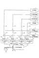
図1は、本発明の実施形態に係る基板洗浄装置を示す。Next, embodiments of the present invention will be described with reference to the drawings.
FIG. 1 shows a substrate cleaning apparatus according to an embodiment of the present invention.
基板洗浄装置本体12内に薬液であるDHF(希フッ酸)を供給するDHF供給部14は、配管14a、第1の切替え部15a及び装置本体内に薬液を供給する第1の配管である配管16aを介して装置本体12に接続されている。また、薬液であるSC1液を供給するSC1洗浄液供給部17は、配管17a、第2の切替え部15b及び第1の配管である配管16bを介して装置本体12に接続されている。また、薬液であるSC2液を供給するSC2洗浄液供給部18は、配管18a、第3の切替え部15c及び第1の配管である配管16cを介して装置本体12に接続されている。 A DHF
基板洗浄装置本体12内にリンス液であるDIWを供給するDIW供給部20は、配管20a、第4の切替え部15d及び装置本体内にリンス液を供給する第2の配管である配管21を介して装置本体12に接続されている。 The DIW
基板洗浄装置本体12内に配管洗浄液である酸化性クリーニング液を供給する酸化性クリーニング液供給部22は、配管22a、22b、22c、22dを介して第1の切替え部15a、第2の切替え部15b、第3の切替え部15c、第4の切替え部15dにそれぞれ接続されている。酸化性クリーニング液としては、例えば過酸化水素水やオゾン水、次亜塩素酸、硝酸、クロラミン、ジメチルスルホキシドのいずれか1種類以上を混合した酸化性の液体が挙げられる。 An oxidizing cleaning
基板洗浄装置本体12内に配管洗浄液である有機溶媒クリーニング液を供給する有機溶媒クリーニング液供給部24は、配管24a、24b、24c、24dを介して第1の切替え部15a、第2の切替え部15b、第3の切替え部15c、第4の切替え部15dにそれぞれ接続されている。有機溶媒クリーニング液としては、例えばメタノール、エタノール、イソプロピルアルコール、n−プロピルアルコール、エチレングリコール、2-メチル-2-プロパノールのいずれか1種類以上を混合した有機溶媒が挙げられる。 An organic solvent cleaning
したがって、DHF供給部14は、配管14a、第1の切替え部15a及び配管16aを介して洗浄装置本体12内にDHFを供給し、第1の切替え部15aが酸化性クリーニング液供給部22側に切替えられることで、装置本体12内へのDHFの供給は停止し、酸化性クリーニング液供給部22に備えられた酸化性クリーニング液が配管22a、第1の切替え部15a及び配管16aを介して装置本体12内に供給される。また、第1の切替え部15aが有機溶媒クリーニング液供給部24側に切替えられることで有機溶媒クリーニング液供給部24に備えられた有機溶媒クリーニング液が配管24a、第1の切替え部15a及び配管16aを介して装置本体12内に供給される。 Therefore, the DHF
また、SC1洗浄液供給部17は、配管17a、第2の切替え部15b及び配管16bを介して洗浄装置本体12内にSC1液を供給し、第2の切替え部15bが酸化性クリーニング液供給部22側に切替えられることで、装置本体12内へのSC1液の供給は停止し、酸化性クリーニング液供給部22に備えられた酸化性クリーニング液が配管22b、第2の切替え部15b及び配管16bを介して装置本体12内に供給される。また、第2の切替え部15bが有機溶媒クリーニング液供給部24側に切替えられることで有機溶媒クリーニング液供給部24に備えられた有機溶媒クリーニング液が配管24b、第2の切替え部15b及び配管16bを介して装置本体12内に供給される。 Further, the SC1 cleaning
また、SC2洗浄液供給部18は、配管18a、第3の切替え部15c及び配管16cを介して洗浄装置本体12内にSC2液を供給し、第3の切替え部15cが酸化性クリーニング液供給部22側に切替えられることで、装置本体12内へのSC2液の供給は停止し、酸化性クリーニング液供給部22に備えられた酸化性クリーニング液が配管22c、第3の切替え部15c及び配管16cを介して装置本体12内に供給される。また、第3の切替え部15cが有機溶媒クリーニング液供給部24側に切替えられることで有機溶媒クリーニング液供給部24に備えられた有機溶媒クリーニング液が配管24c、第3の切替え部15c及び配管16cを介して装置本体12内に供給される。 Further, the SC2 cleaning
さらに、DIW供給部20は、配管20a、第4の切替え部15d及び配管21を介して洗浄装置本体12内にDIWを供給し、第4の切替え部15dが酸化性クリーニング液供給部22側に切替えられることで、装置本体12内へのDIWの供給は停止し、酸化性クリーニング液供給部22に備えられた酸化性クリーニング液が配管22d、第4の切替え部15d及び配管21を介して装置本体12内に供給される。また、第4の切替え部15dが有機溶媒クリーニング液供給部24側に切替えられることで有機溶媒クリーニング液供給部24に備えられた有機溶媒クリーニング液が配管24d、第4の切替え部15d及び配管21を介して装置本体12内に供給される。 Further, the DIW
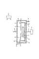
図2は、本発明の実施形態に係る基板洗浄装置10の装置本体12内を示す。
基板洗浄装置本体(洗浄容器)12に囲まれて洗浄室30が構成されている。この洗浄室30には、半導体ウエハ等の基板32を水平に支持する支持具34が配置されている。この支持具34は、モータ等からなる回転機構36に回転軸37を介して接続され、この回転機構36により、水平に支持された状態の基板32を回転させるようになっている。FIG. 2 shows the inside of the apparatus
A
支持具34の周囲はカバー38により囲まれている。このカバー38は、後述するように、支持具34により基板32が回転する際に基板32から飛ぶ薬液を受け止めるようになっている。 The periphery of the
装置本体12の側面には、基板搬入搬出口33(図1参照)が形成されている。この基板搬入搬出口33にはゲートバルブ35(図1参照)が設けられており、このゲートバルブ35により基板搬入搬出口33が開閉される。また、この基板搬入搬出口33を介して基板32を支持具34に移載するための基板移載機39(図1参照)が設けられている。 A substrate loading / unloading port 33 (see FIG. 1) is formed on the side surface of the
前述した洗浄室30には、第1のノズル40と第2のノズル42とが挿入されている。第1のノズル40は薬液である例えばDHF、SC1液、SC2液を供給する第1の配管(配管16a、16b、16c)に接続され、第2のノズル42はリンス液である例えばDIWを供給する第2の配管(配管21)に接続され、第1のノズル40と第2のノズル42とは、それぞれの先端が支持具34に支持された基板32の中心付近手前まで延びるように水平に配置されている。したがって、第1のノズル40からは第1の配管である配管16a、16b、16cを介してDHF、SC1液、SC2液が基板32の中心に供給される。また、第2のノズル42からは第2の配管である配管21を介してDIWが基板32の中心に供給される。また、第1の切替え部15a、第2の切替え部15b、第3の切替え部15c又は第4の切替え部15dが酸化性クリーニング液供給部側、または有機溶媒クリーニング液供給部側に切替えられることで、配管洗浄液である酸化性クリーニング液または有機溶媒クリーニング液が配管16a、16b、16c又は配管21内に供給され、第1のノズル40及び第2のノズル42の両方又は少なくとも一方から基板洗浄装置本体12内に供給される。 A
給水部50は、前述したカバー38の内側上部の周囲に開口し、カバー38の内面に純水(脱イオン水)を供給できるようになっている。 The
カバー38の下面には、カバー38に供給された純水を排出するための排水管54が接続されており、この排水管54は、基板洗浄装置本体12の外部へ延び、この排水管54を介してカバー38内の純水が排出される。なお、基板32に対して供給された薬液やリンス液も排水管54を介して排出される。 A
また、基板洗浄装置本体12の上部には、乾燥用ガス供給管56が接続されている。乾燥用ガスとしては、例えば窒素(N2)が用いられる。さらに、基板洗浄装置本体12の下部には乾燥用ガスを排出するための排気管60が接続されている。A drying
コントローラ62はコンピュータから構成され、回転機構36による支持具34の回転、ゲートバルブ35による基板搬入搬出口33の開閉、基板移載機39による基板32の搬入及び搬出、第1のノズル40によるDHF、SC1液、SC2液の供給、第2のノズル42によるDIWの供給、配管16a、16b、16c、21内への酸化性クリーニング液の供給、配管16a、16b、16c、21内への有機溶媒クリーニング液の供給、第1の切替え部15a、第2の切替え部15b、第3の切替え部15c及び第4の切替え部15dの各切替え作業、給水部50からの純水の供給、乾燥用ガス供給管56からの窒素(N2)の供給等を制御する。The
次に、上記構成に係る基板洗浄装置10を用いて半導体装置(デバイス)の製造工程の一工程として、基板を洗浄する方法について説明する。 Next, a method for cleaning a substrate will be described as one step of a semiconductor device (device) manufacturing process using the substrate cleaning apparatus 10 having the above-described configuration.
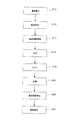
図3は、コントローラ62による制御フローを示すフローチャートである。
まず、ステップS10において、ゲートバルブ35により基板搬入搬出口33を開き、パターンが形成された基板32を基板移載機39により洗浄室30内に搬入する。FIG. 3 is a flowchart showing a control flow by the
First, in step S <b> 10, the substrate loading / unloading
次のステップS12においては、さらに基板移載機39を制御して基板32を支持具34に支持(セット)し、ゲートバルブ35により基板搬入搬出口33を閉じる。 In the
次のステップS14においては、回転機構36により回転軸37を介して支持具34を回転させることにより基板32の回転を開始する。 In the next step S <b> 14, the rotation of the
次のステップS16においては、図4に示すように、基板32の回転を維持しつつ、第1の切替え部15aをDHF供給部14側に切替え、第1の配管である配管16aを介して第1のノズル40からDHFを供給し、基板32の表面を洗浄する。このとき、第2の切替え部15bをSC1洗浄液供給部17側に切替え、配管16bを介して第1のノズル40からSC1洗浄液を供給するようにしてもよいし、第3の切替え部15cをSC2洗浄液供給部18側に切替え、配管16cを介して第1のノズル40からSC2洗浄液を供給するようにしてもよい。 In the next step S16, as shown in FIG. 4, the
次のステップS18においては、図5に示すように、基板32の回転を維持しつつ、第1のノズル40からのDHFの供給を停止し、第4の切替え部15dをDIW供給部20側に切替え、第2の配管である配管21を介して第2のノズル42からリンス液としてのDIWを基板32の中心に向けて供給し、基板表面に残留するDHFを洗い流し、リンスを行う。 In the next step S18, as shown in FIG. 5, while the rotation of the
次のステップS20においては、図6に示すように、基板32の回転を維持しつつ、第2のノズル42からのDIWの供給を停止し、基板上のDIW等を回転による遠心力でふるい落とす。このステップS20においては、洗浄室30には、乾燥用ガス供給管56を介して乾燥用ガスとしてのN2を供給しつつ排気管58より排気して洗浄室30をN2雰囲気とし、このN2雰囲気中で基板32を乾燥させる。
なお、給水部50からカバー38の内面への水の供給は、安全性を高めるため、ステップS16の洗浄工程または、ステップS18のリンス工程からステップS20の乾燥工程にかけて連続的に行うのが好ましい。即ち、少なくとも基板32からDHFやDIW等がカバー38へ飛ぶ間はカバー38の内面に純水を供給するようにするのがよい。なお、後述する配管洗浄工程においてもカバー38の内面に純水を供給するようにするのがよい。In the next step S20, as shown in FIG. 6, while the rotation of the
In addition, in order to improve safety, it is preferable to continuously supply water from the
次のステップS22においては、回転機構36による支持具34の回転を停止することにより基板32の回転を停止する。また、洗浄室30内へのN2の供給を停止する。In the next step S <b> 22, the rotation of the
次のステップS24によれば、ゲートバルブ35により基板搬入搬出口33を開き、基板移載機39により基板32を洗浄室30内から搬出する。その後、他の装置、例えばエピタキシャル成長装置等へ搬送し、成膜等の処理を行う。 According to the next step S24, the substrate loading / unloading
本発明においては、必要に応じて、例えば上述のステップS10からステップS24の一連の基板洗浄工程以外の時にDHFを供給する第1の切替え部15a及びDIWを供給する第4の切替え部15dの両方又は少なくとも一方を酸化性クリーニング液供給部22側に切替える。そして、酸化性クリーニング液供給部22から過酸化水素水やオゾン水等の酸化性の液体を流すことで、この酸化性の液体を第1の切替え部15aを介して第1の配管である配管16a内へ、また、第4の切替え部15dを介して第2の配管である配管21内へ流すことができる。配管16a内、21内へ流れた酸化性の液体は、第1のノズル40、第2のノズル42を介して洗浄装置本体12内に供給され、排水管54より排出される。これにより、第1及び第2の配管内、第1のノズル40、第2のノズル42内、装置本体12内に蓄積した有機物を酸化分解し、系外へ排出させることができる。 In the present invention, if necessary, for example, both the
また、DHFの代わりにSC1液又はSC2液を使用する場合にも、必要に応じて、SC1液又はSC2液を供給する第2の切替え部15b又は第3の切替え部15cを酸化性クリーニング液供給部22側に切替え、酸化性クリーニング液供給部22から過酸化水素水やオゾン水等の酸化性の液体を流すことで、この酸化性の液体を第2の切替え部15b又は第3の切替え部15cを介して第1の配管である配管16b内又は配管16c内へ流すことができる。配管16b内、16c内へ流れた酸化性の液体は第1のノズル40を介して洗浄装置本体12内に供給され、排水管54より排出される。これにより第1の配管内、第1のノズル40内、装置本体12内に蓄積した有機物を酸化分解し、系外へ排出させることができる。 Further, when the SC1 liquid or the SC2 liquid is used instead of DHF, the
また、第1及び第2の配管内、第1のノズル40、第2のノズル42内、洗浄装置本体12内に蓄積した有機物の除去に際しては、酸化性クリーニング液供給部22の代わりに有機溶媒クリーニング液供給部24を用いてもよい。
有機溶媒を第1の配管内及び第2の配管内の両方又は少なくとも一方に流すことで、第1及び第2の配管内、第1のノズル40、第2のノズル42内、洗浄装置本体12内に蓄積した有機物を直接溶解させて、系外へ排出させることができる。When removing organic substances accumulated in the first and second pipes, the
By flowing the organic solvent through both or at least one of the first pipe and the second pipe, the
また、これら2種類の液体(酸化性の液体、有機溶媒)をそれぞれの配管に応じて1種類以上若しくは内容や濃度を個別に変化させて(例えば第1の配管にはIPA,第2の配管にはメタノールなど)流してもよい。但し、配管洗浄液供給系において、酸化性の液体と有機溶媒の両方を用いる場合は、それぞれの液体によるクリーニング工程の間に、DIWによる配管内置換が必要となり、このための設備も設ける必要がある。 In addition, one or more of these two types of liquids (oxidizing liquid and organic solvent) are changed according to the respective pipes, or the contents and concentration are individually changed (for example, IPA and second pipes are used for the first pipe). Or methanol). However, when both an oxidizing liquid and an organic solvent are used in the pipe cleaning liquid supply system, it is necessary to replace the pipe with DIW during the cleaning process with each liquid, and it is also necessary to provide equipment for this purpose. .
薬液やDIWを装置内部のユースポイントまで供給する配管やバルブ等からは可塑剤として加えられているフタル酸エステル類やフッ素化合物等が微量ながら溶出する。また供給タンクから装置までの配管やバルブ等によっても有機化合物は微量ながら溶出する。これらの有機物は装置内部のタンク壁や配管壁、流路上の僅かなデッドスペースなどに蓄積され、別のタイミング(温度や振動などの影響)で再溶出し洗浄中のウエハに付着する。本発明では、装置内部をセルフクリーニングすることで、装置内部に蓄積した有機物等を系外へ排出できるようにすることを最大の特徴とする。 A small amount of phthalates and fluorine compounds added as plasticizers are eluted from pipes and valves that supply chemicals and DIW to the use point inside the equipment. In addition, organic compounds are eluted in a trace amount by piping and valves from the supply tank to the apparatus. These organic substances are accumulated in the tank wall and piping wall inside the apparatus, a slight dead space on the flow path, etc., re-eluted at another timing (effect of temperature, vibration, etc.) and adhere to the wafer being cleaned. The greatest feature of the present invention is that the organic matter accumulated in the apparatus can be discharged out of the system by self-cleaning the inside of the apparatus.
本発明によれば、使用する薬液やDIWの配管に本来使用する薬液とは異なる過酸化水素水やオゾン水、イソプロピルアルコール等を別途加えることで、装置内部に蓄積した有機汚染物質を分解・溶解し、クリーニング処理を行うことができる。さらに、これによって、ウエハ洗浄時におけるウエハへの有機汚染物質の付着を抑制し、ウエハを清浄に保つことができ、表面洗浄度に敏感な成膜工程前のウエハ洗浄に利用することができる。
以下、本発明の好ましい態様について付記する。According to the present invention, by separately adding hydrogen peroxide water, ozone water, isopropyl alcohol, etc., which are different from the chemical solution originally used to the chemical solution or DIW piping, the organic pollutants accumulated in the apparatus are decomposed and dissolved. In addition, a cleaning process can be performed. In addition, this prevents organic contaminants from adhering to the wafer during wafer cleaning, keeps the wafer clean, and can be used for wafer cleaning prior to a film forming process sensitive to the degree of surface cleaning.
Hereinafter, preferred embodiments of the present invention will be additionally described.
本発明の一態様によれば、基板を薬液により洗浄する処理室と、前記処理室内で基板を支持する支持具と、前記処理室内の前記基板に対して薬液を供給する第1の配管と、前記処理室内の前記基板に対してリンス液を供給する第2の配管と、前記第1の配管及び前記第2の配管内の少なくとも一方に配管洗浄液を供給する配管洗浄液供給系と、を有する基板洗浄装置が提供される。 According to one aspect of the present invention, a processing chamber that cleans a substrate with a chemical solution, a support that supports the substrate in the processing chamber, a first pipe that supplies the chemical solution to the substrate in the processing chamber, A substrate having a second pipe for supplying a rinsing liquid to the substrate in the processing chamber, and a pipe cleaning liquid supply system for supplying a pipe cleaning liquid to at least one of the first pipe and the second pipe. A cleaning device is provided.
好ましくは、前記薬液は、酸またはアルカリ等(例えばフッ化水素、塩酸、硫酸、またはアンモニア水、過酸化水素水)を1種類以上混ぜ、脱イオン水(DIW)で希釈したものや、機能水と呼ばれる脱イオン水(DIW)にオゾンガスや水素ガスを溶解させたものである。 Preferably, the chemical solution is a mixture of one or more acids or alkalis (for example, hydrogen fluoride, hydrochloric acid, sulfuric acid, ammonia water, hydrogen peroxide water) diluted with deionized water (DIW), or functional water. Ozone gas and hydrogen gas are dissolved in deionized water (DIW).
好ましくは、前記薬液は、希フッ酸(DHF),アンモニア水と過酸化水素水を混ぜDIWで希釈したもの(SC1),または塩酸と過酸化水素水を混ぜDIWで希釈したもの(SC2)である。 Preferably, the chemical solution is dilute hydrofluoric acid (DHF), a mixture of ammonia water and hydrogen peroxide solution diluted with DIW (SC1), or a mixture of hydrochloric acid and hydrogen peroxide solution diluted with DIW (SC2). is there.
好ましくは、前記リンス液は、炭酸ガスを溶解させた水である。 Preferably, the rinse liquid is water in which carbon dioxide gas is dissolved.
好ましくは、前記リンス液は、脱イオン水(DIW)である。 Preferably, the rinse liquid is deionized water (DIW).
好ましくは、前記洗浄液は、過酸化水素水、オゾン水、次亜塩素酸、硝酸、クロラミン、ジメチルスルホキシドのいずれか1種類以上を混合した酸化性の液体である。 Preferably, the cleaning liquid is an oxidizing liquid in which one or more of hydrogen peroxide water, ozone water, hypochlorous acid, nitric acid, chloramine, and dimethyl sulfoxide are mixed.
好ましくは、前記洗浄液は、メタノール、エタノール、イソプロピルアルコール、n−プロピルアルコール、エチレングリコール、2−メチル−2−プロパノールのいずれか1種類以上を混合した有機溶媒である。 Preferably, the cleaning liquid is an organic solvent in which at least one of methanol, ethanol, isopropyl alcohol, n-propyl alcohol, ethylene glycol, and 2-methyl-2-propanol is mixed.
好ましくは、上記酸化性の液体の濃度が10重量%以下である。 Preferably, the concentration of the oxidizing liquid is 10% by weight or less.
好ましくは、上記酸化性の液体の濃度が1重量%以下である。 Preferably, the concentration of the oxidizing liquid is 1% by weight or less.
好ましくは、上記酸化性の液体の濃度が0.1重量%以下である。 Preferably, the concentration of the oxidizing liquid is 0.1% by weight or less.
好ましくは、上記酸化性の液体の濃度が0.01重量%以下である。 Preferably, the concentration of the oxidizing liquid is 0.01% by weight or less.
好ましくは、上記有機溶媒の濃度が10重量%以下である。 Preferably, the concentration of the organic solvent is 10% by weight or less.
好ましくは、上記有機溶媒の濃度が1重量%以下である。 Preferably, the concentration of the organic solvent is 1% by weight or less.
好ましくは、上記有機溶媒の濃度が0.1重量%以下である。 Preferably, the concentration of the organic solvent is 0.1% by weight or less.
好ましくは、上記有機溶媒の濃度が0.01重量%以下である。 Preferably, the concentration of the organic solvent is 0.01% by weight or less.
10 基板洗浄装置
12 基板洗浄装置本体
14 DHF供給部
17 SC1洗浄液供給部
18 SC2洗浄液供給部
20 DIW供給部
22 酸化性クリーニング液供給部
24 有機溶媒クリーニング液供給部
30 洗浄室
32 基板
34 支持具DESCRIPTION OF SYMBOLS 10
Claims (1)
Translated fromJapanese前記処理室内で基板を支持する支持具と、
前記処理室内の前記基板に対して薬液を供給する第1の配管と、
前記処理室内の前記基板に対してリンス液を供給する第2の配管と、
前記第1の配管内及び前記第2の配管内の少なくとも一方に配管洗浄液を供給する配管洗浄液供給系と、
を有することを特徴とする基板洗浄装置。A processing chamber for cleaning the substrate with a chemical solution;
A support for supporting the substrate in the processing chamber;
A first pipe for supplying a chemical to the substrate in the processing chamber;
A second pipe for supplying a rinsing liquid to the substrate in the processing chamber;
A pipe cleaning liquid supply system for supplying pipe cleaning liquid to at least one of the first pipe and the second pipe;
A substrate cleaning apparatus comprising:
Priority Applications (1)
| Application Number | Priority Date | Filing Date | Title |
|---|---|---|---|
| JP2008217996AJP2010056208A (en) | 2008-08-27 | 2008-08-27 | Substrate cleaning device |
Applications Claiming Priority (1)
| Application Number | Priority Date | Filing Date | Title |
|---|---|---|---|
| JP2008217996AJP2010056208A (en) | 2008-08-27 | 2008-08-27 | Substrate cleaning device |
Publications (1)
| Publication Number | Publication Date |
|---|---|
| JP2010056208Atrue JP2010056208A (en) | 2010-03-11 |
Family
ID=42071829
Family Applications (1)
| Application Number | Title | Priority Date | Filing Date |
|---|---|---|---|
| JP2008217996APendingJP2010056208A (en) | 2008-08-27 | 2008-08-27 | Substrate cleaning device |
Country Status (1)
| Country | Link |
|---|---|
| JP (1) | JP2010056208A (en) |
Cited By (6)
| Publication number | Priority date | Publication date | Assignee | Title |
|---|---|---|---|---|
| JP2014074215A (en)* | 2012-10-05 | 2014-04-24 | Taiyo Nippon Sanso Corp | Cleaning method for gas-phase growth apparatus piping, and gas-phase growth apparatus |
| JPWO2014013902A1 (en)* | 2012-07-19 | 2016-06-30 | 日産化学工業株式会社 | Cleaning liquid for semiconductor and cleaning method using the same |
| JP2020155649A (en)* | 2019-03-20 | 2020-09-24 | 株式会社Screenホールディングス | Substrate processing equipment and piping cleaning method for substrate processing equipment |
| CN113348534A (en)* | 2019-01-23 | 2021-09-03 | 东京毅力科创株式会社 | Substrate processing apparatus and substrate processing method |
| JP2023012573A (en)* | 2021-07-14 | 2023-01-26 | 東京エレクトロン株式会社 | Substrate processing equipment |
| JP2023032028A (en)* | 2021-08-26 | 2023-03-09 | 株式会社荏原製作所 | Substrate processing device, method for cleaning piping in the same |
- 2008
- 2008-08-27JPJP2008217996Apatent/JP2010056208A/enactivePending
Cited By (9)
| Publication number | Priority date | Publication date | Assignee | Title |
|---|---|---|---|---|
| JPWO2014013902A1 (en)* | 2012-07-19 | 2016-06-30 | 日産化学工業株式会社 | Cleaning liquid for semiconductor and cleaning method using the same |
| JP2014074215A (en)* | 2012-10-05 | 2014-04-24 | Taiyo Nippon Sanso Corp | Cleaning method for gas-phase growth apparatus piping, and gas-phase growth apparatus |
| CN113348534A (en)* | 2019-01-23 | 2021-09-03 | 东京毅力科创株式会社 | Substrate processing apparatus and substrate processing method |
| CN113348534B (en)* | 2019-01-23 | 2024-03-26 | 东京毅力科创株式会社 | Substrate processing device and substrate processing method |
| JP2020155649A (en)* | 2019-03-20 | 2020-09-24 | 株式会社Screenホールディングス | Substrate processing equipment and piping cleaning method for substrate processing equipment |
| JP7302997B2 (en) | 2019-03-20 | 2023-07-04 | 株式会社Screenホールディングス | SUBSTRATE PROCESSING APPARATUS AND PIPE CLEANING METHOD OF SUBSTRATE PROCESSING APPARATUS |
| JP2023012573A (en)* | 2021-07-14 | 2023-01-26 | 東京エレクトロン株式会社 | Substrate processing equipment |
| JP2023032028A (en)* | 2021-08-26 | 2023-03-09 | 株式会社荏原製作所 | Substrate processing device, method for cleaning piping in the same |
| JP7734532B2 (en) | 2021-08-26 | 2025-09-05 | 株式会社荏原製作所 | Substrate processing apparatus and method for cleaning piping in substrate processing apparatus |
Similar Documents
| Publication | Publication Date | Title |
|---|---|---|
| JP7080134B2 (en) | Particle removal method of board processing device and board processing device | |
| CN100501921C (en) | Substrate processing method and substrate processing apparatus | |
| WO2006137330A1 (en) | Substrate processing apparatus and substrate processing method | |
| JP7149087B2 (en) | Substrate processing method and substrate processing apparatus | |
| JP2010056208A (en) | Substrate cleaning device | |
| JP2009543344A (en) | Post-etch wafer surface cleaning with liquid meniscus | |
| JP2007012859A (en) | Equipment and method for processing substrate | |
| JP4763756B2 (en) | Method for cleaning, drying and hydrophilizing a semiconductor wafer | |
| JP2002050600A (en) | Substrate-processing method and substrate processor | |
| JP4791905B2 (en) | Substrate cleaning method | |
| KR101021544B1 (en) | Substrate processing apparatus and substrate processing method thereof | |
| JP2008311266A (en) | Semiconductor device manufacturing method and substrate cleaning apparatus | |
| CN101001704A (en) | System and method for carrying out liquid and subsequent drying treatments on one or more wafers | |
| JP4484639B2 (en) | Substrate processing method and substrate processing apparatus | |
| JP2006278955A (en) | Method and device for substrate processing | |
| JP7703568B2 (en) | Method and apparatus for removing particles or photoresist on a substrate - Patents.com | |
| KR100825965B1 (en) | Substrate Cleaning Method | |
| JP2000308859A (en) | Treating device and treating method | |
| KR100436900B1 (en) | Apparatus for cleaning wafers | |
| JP2000340632A (en) | Substrate chemical treatment apparatus and substrate chemical treatment method | |
| JP2005051101A (en) | Method of cleaning substrate | |
| JP2005051099A (en) | Method of cleaning substrate | |
| JP4357456B2 (en) | Semiconductor substrate cleaning method | |
| JP6020626B2 (en) | Device Ge substrate cleaning method, cleaning water supply device and cleaning device | |
| JP2003297792A (en) | Substrate cleaning method, cleaning and drying apparatus, and semiconductor device manufacturing method |