JP2010054096A - Liquid supply/discharge device, steam generator using the same, cleaning method of liquid supply/discharge device, and cleaning method of steam generator - Google Patents
Liquid supply/discharge device, steam generator using the same, cleaning method of liquid supply/discharge device, and cleaning method of steam generatorDownload PDFInfo
- Publication number
- JP2010054096A JP2010054096AJP2008218114AJP2008218114AJP2010054096AJP 2010054096 AJP2010054096 AJP 2010054096AJP 2008218114 AJP2008218114 AJP 2008218114AJP 2008218114 AJP2008218114 AJP 2008218114AJP 2010054096 AJP2010054096 AJP 2010054096A
- Authority
- JP
- Japan
- Prior art keywords
- tank
- liquid
- drainage
- steam generator
- liquid supply
- Prior art date
- Legal status (The legal status is an assumption and is not a legal conclusion. Google has not performed a legal analysis and makes no representation as to the accuracy of the status listed.)
- Pending
Links
Images


Landscapes
- Cleaning By Liquid Or Steam (AREA)
Abstract
Translated fromJapaneseDescription
Translated fromJapanese本発明は、給排液装置及びこれを用いる蒸気発生装置、給排液装置の洗浄方法、及び蒸気発生装置の洗浄方法に関する。 The present invention relates to a supply / drainage device, a steam generator using the same, a cleaning method for the supply / drainage device, and a cleaning method for the steam generation device.
第1タンクから第2タンクに必要なだけの液体を給液し、第2タンクでの用が済んだ液体を第2タンクから排液する給排液装置は、様々な産業分野で利用されている。その例を特許文献1、2に見ることができる。 2. Description of the Related Art A supply / drainage device that supplies only necessary liquid from a first tank to a second tank and drains liquid that has been used in the second tank from the second tank is used in various industrial fields. Yes. Examples thereof can be seen in
特許文献1には加熱調理器に用いられる蒸気発生装置が記載されている。第1タンクである給水タンクの水を第2タンクである蒸発容器に給水ポンプで給水する。蒸発容器の中の水は、蒸発容器の底部に接続された排水管の排水弁を開くことにより排水される。
特許文献2には蒸気調理器に用いられる蒸気発生装置が記載されている。第1タンクである水タンクの水を第2タンクであるポットにポンプで給水する。ポットの中の水は、ポットの底部に接続された排水パイプの排水バルブを開くことにより排水される。
特許文献1や特許文献2に記載された給排液装置は、第2タンクの底部に接続された電磁弁を開いて第2タンクの中の液体を排液している。この構成であると、排液用に電磁弁が必要である上、その電磁弁の故障を懸念しなければならない。特にその電磁弁が、蒸気発生装置の蒸発容器に接続されている場合、電磁弁を通る液体はスケールの組成物質である不純物が濃縮された液体であることが多く、電磁弁内部にスケールが発生することによる故障の可能性を排除できない。 The supply / drainage device described in
本発明は上記の点に鑑みなされたものであり、排液の仕組みが簡素化された、故障の少ない給排液装置を提供することを目的とする。また、かかる給排液装置を用いた故障の少ない蒸気発生装置を提供することを目的とする。さらに、このような給排液装置または上記発生装置を十分に洗浄する方法を提供することを目的とする。 The present invention has been made in view of the above points, and an object of the present invention is to provide a supply / drainage device that has a simplified drainage mechanism and has few failures. It is another object of the present invention to provide a steam generator with less failure using such a supply / drainage device. Furthermore, it aims at providing the method of fully wash | cleaning such a supply / drainage apparatus or the said generator.
上記目的を達成するために、本発明に係る給排液装置は、第1タンクと、前記第1タンクよりも高位に配置された第2タンクと、前記第1タンク内の液体を前記第2タンクに汲み上げる給液ポンプと、前記第2タンクの底部に接続され、前記底部より所定高さ上のレベルを頂点とする屈曲ラインを描いた上で、前記底部より下の位置に設けられた排液口まで下がる排液管と、前記第2タンクに設けられた液位検知装置と、前記給液ポンプの制御を行う制御装置と、を備え、前記制御装置は、前記第2タンク内の液位が前記排液管の頂点より下のレベルに保たれるように前記給液ポンプを駆動する通常時運転制御と、前記第2タンク内の液位が一時的に前記排液管の頂点を越えるレベルに達するまで前記給液ポンプを駆動する排液時運転制御を遂行することを特徴としている。 In order to achieve the above object, a water supply / drainage device according to the present invention includes a first tank, a second tank disposed higher than the first tank, and liquid in the first tank as the second tank. A liquid supply pump that is pumped into the tank, and a drain line that is connected to the bottom of the second tank and has a bent line with the level at a predetermined height above the bottom as a vertex, and is provided at a position below the bottom. A drainage pipe that descends to a liquid port; a liquid level detection device provided in the second tank; and a control device that controls the liquid supply pump, wherein the control device includes liquid in the second tank. A normal operation control for driving the liquid supply pump so that the position is maintained at a level below the top of the drainage pipe, and the liquid level in the second tank temporarily reaches the top of the drainage pipe. Operation control at the time of drainage that drives the feed pump until it reaches a level exceeding It is characterized by rows.
第2タンク内の液位が一時的に排液管の頂点を越えるレベルに達するまで第2タンクに給液すると、排液管にサイフォン現象が生じ、第2タンク内の液体は残らず排液される。排液用の電磁弁が存在しないので部品コストが安くつき、排液系統に故障が生じる可能性は小さい。また給液ポンプの運転制御だけで排液を実現できるので、制御設計も容易である。 When the liquid level in the second tank temporarily reaches the level exceeding the top of the drain pipe, the siphon phenomenon occurs in the drain pipe and the liquid in the second tank does not remain and drains. Is done. Since there is no solenoid valve for drainage, the parts cost is low, and the possibility of failure in the drainage system is small. Moreover, since the drainage can be realized only by the operation control of the liquid supply pump, the control design is easy.
また本発明は、上記構成の給排液装置において、前記排液管は前記第1タンクに排液することを特徴としている。 According to the present invention, in the supply / drainage device having the above-described configuration, the drainage pipe drains into the first tank.
この構成によると、液体の循環使用が可能になり、液体のランニングコストを低減できる。 According to this configuration, it becomes possible to circulate and use the liquid, and the running cost of the liquid can be reduced.
また本発明は、上記構成の給排液装置を用いる蒸気発生装置であって、前記第1タンクを液源として用い、前記第2タンクを蒸発容器として用いることを特徴としている。 Further, the present invention is a steam generating apparatus using the supply / drainage apparatus having the above-described configuration, wherein the first tank is used as a liquid source and the second tank is used as an evaporation container.
この構成によると、長時間蒸気を発生させた結果、不純物を多く含む液体が蒸発容器に溜まっていたとしても、それを電磁弁経由でなく排液するから、電磁弁内部にスケールが付着して電磁弁が故障するといった事態を迎えずに済む。 According to this configuration, even if a liquid containing a large amount of impurities accumulates in the evaporation container as a result of generating steam for a long time, the liquid is discharged not via the solenoid valve. It is not necessary for the solenoid valve to fail.
また本発明は、上記構成の給排液装置において、前記第1タンクに洗浄液を入れ、前記排液時運転制御を複数回実行することを特徴としている。 Further, the present invention is characterized in that, in the supply / drainage device having the above-described configuration, a cleaning liquid is put into the first tank, and the operation control during drainage is executed a plurality of times.
この構成によると、給排液装置の第2タンクを十分に洗浄することができる。第2タンクからの排液経路を洗浄液が何度も通るにも関わらず、そこに電磁弁は存在しないので、排液経路中の電磁弁が洗浄液で傷むという心配をする必要がない。 According to this configuration, the second tank of the supply / drainage device can be sufficiently cleaned. Even though the cleaning liquid passes through the drainage path from the second tank many times, there is no electromagnetic valve there, so there is no need to worry that the electromagnetic valve in the drainage path is damaged by the cleaning liquid.
また本発明は、上記構成の蒸気発生装置において、前記第1タンクに洗浄液を入れ、前記排液時運転制御を複数回実行することを特徴としている。 According to the present invention, in the steam generator configured as described above, a cleaning liquid is placed in the first tank, and the drain operation control is executed a plurality of times.
この構成によると、蒸気発生装置の第2タンクを十分に洗浄することができる。第2タンクからの排液経路を洗浄液が何度も通るにも関わらず、そこに電磁弁は存在しないので、排液経路中の電磁弁が洗浄液で傷むという心配をする必要がない。 According to this configuration, the second tank of the steam generator can be sufficiently cleaned. Even though the cleaning liquid passes through the drainage path from the second tank many times, there is no electromagnetic valve there, so there is no need to worry that the electromagnetic valve in the drainage path is damaged by the cleaning liquid.
本発明によると、第1タンクより給液される第2タンクからの排液を、サイフォン現象を利用して、電磁弁を用いることなく行うから、部品コストが安くつき、電磁弁が故障する懸念もない。また給液ポンプの運転制御だけで排液を実現できるので、制御設計も容易である。 According to the present invention, since the drainage from the second tank supplied from the first tank is performed without using the solenoid valve using the siphon phenomenon, the parts cost is low and the solenoid valve may be broken. Nor. Moreover, since the drainage can be realized only by the operation control of the liquid supply pump, the control design is easy.
以下本発明の実施形態を図1から図5に基づき説明する。本実施形態では給排液装置が蒸気発生装置の形で実現されており、図1から図4までは蒸気発生装置の概略構成図にしてそれぞれ異なる状態を示す。図5は第2タンクを洗浄する洗浄コースのフローチャートである。 Hereinafter, embodiments of the present invention will be described with reference to FIGS. In the present embodiment, the supply / drainage device is realized in the form of a steam generator, and FIGS. 1 to 4 show different states in schematic configuration diagrams of the steam generator. FIG. 5 is a flowchart of a cleaning course for cleaning the second tank.
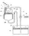
蒸気発生装置1は、液源として用いられる第1タンク10と、蒸発容器である第2タンク20を備える。第2タンク20は第1タンク10よりも高位に配置される。 The
第1タンク10は十分な容量を備えておりさえすればよく、材質や形状に限定はない。第1タンク10からは、その中の液体Lを第2タンク20に移すための給液管11が立ち上がる。給液管11は第2タンク20の頂部20Tに接続されるものであり、途中に給液ポンプ12が設けられている。給液ポンプ12は制御装置30により駆動制御される。 The
蒸発容器として構成される第2タンク20は、熱伝導の良い金属を略円筒形の容器の形に仕上げたものであり、ドーム形の頂部20Tと漏斗形の底部20Bを有する。第2タンク20の胴部の外側をシーズヒータや誘導加熱コイル等のヒータ21が取り巻く。ヒータ21は制御装置30により通電制御される。第2タンク20の頂部20Tには、その中心の最も高くなった箇所に蒸気放出管22が接続されている。頂部20Tには、長短3本の電極23a、23b、23cにより構成される液位検知装置23も配置される。 The
第2タンク20の底部20Bには、その中心の最も低くなった箇所に、排液管24が接続される。排液管24は一旦上方に持ち上がり、底部20Bより所定高さ上のレベルを頂点24Sとする屈曲ラインを描いた上で、底部20Bより下の位置に設けられた排液口24Dまで下がっている。実施形態では、排液管24は第1タンク10に導入されており、第1タンク10の天井面より下で、液体Lの液面より上の位置に、排液口24Dが設けられている。 A
液位検知装置23を構成する3本の電極の中で、最も短い電極23cの下端は、排液管24の頂点24Sより少し上のレベルにある。中間の長さの電極23bの下端は、排液管24の頂点24Sより少し下のレベルにある。最も長い電極23aの下端は、電極23bの下端よりさらに下のレベルにある。この状況を最も良く示すのが図4である。 Among the three electrodes constituting the liquid
蒸気発生装置1の動作は次の通りである。蒸気を発生させるときは、第1タンク10の中に十分な量の液体L(水蒸気を発生させるのであれば水)を入れておき、それを給液ポンプ12で第2タンク20に汲み上げる。図1に示すように、液体Lの液位が電極23bの下端に届いたところで給液ポンプ12の運転を停止する。そしてヒータ21に通電し、液体Lの加熱を開始する。やがて液体Lは沸騰し、蒸気が発生する。蒸気はそれを必要とする箇所へ蒸気放出管22を通じて導かれる。 The operation of the
蒸気を発生させ続けていると、第2タンク20の中の液体Lの量が減少し、液位が下がって行く。図2に示すように、電極23aの下端よりも下のレベルまで液位が下がると、給液ポンプ12の運転が再開され、第1タンク10から新たな液体Lが第2タンク20に供給される。第2タンク20の中の液位が電極23bの下端に届いたら給液ポンプ12の運転は停止される。このように、第2タンク20内の液位が排液管24の頂点24Sより下のレベルに保たれるように給液ポンプ12を駆動する制御(これを「通常時運転制御」と称する)を、制御部30は蒸気発生期間中実行し続ける。 If the steam is continuously generated, the amount of the liquid L in the
蒸気発生装置1を休止状態にするときは、第2タンク20を空にするのが望ましい。第2タンク20を空にするとの指令を受けた制御部30は、図3に示すように、第2タンク内の液位が電極23cの下端に届くまで、給液ポンプ12を駆動する。電極23cの下端に液位が届いたら給液ポンプ12の駆動を停止する。制御部30によるこのような制御を「排液時運転制御」と称する。 When putting the
前述の通り、電極23cの下端は排液管24の頂点24Sより少し上のレベルにあるので、ここまで液体Lを入れると、第2タンク20内の液位は一時的に排液管24の頂点を越えるレベルに達することになる。排液管24の内部も頂点24Sまで液体Lで満たされる。すると排液管24にサイフォン現象が生じ、第2タンク20の中の液体Lは排液管24を通じて吸い出され、排液口24Dから放出される。一旦サイフォン現象が生じると、図4に示すように、第2タンク20がすっかり空になるまで液体Lの流出が続く。 As described above, since the lower end of the
このように、排液用の電磁弁を用いることなく第2タンク20から排液できるから、部品コストが安くつき、液体Lの中にスケールの組成物質である不純物が濃縮されていたとしても、排液系統に故障が生じる可能性は小さい。また給液ポンプ12の運転制御だけで排液を実現できるので、制御設計も容易である。 In this way, since the liquid can be drained from the
排液口24Dは第1タンク10の内部に開口しているので、液体Lは第1タンク10に戻り、循環使用されることになる。これにより液体Lのランニングコストを低減できる。 Since the
長期にわたり蒸気発生装置1を使用していると、装置各所、特に第2タンク20の内面にスケールが付着する。この時は、第1タンク10に洗浄液を入れ、図5に示す洗浄コースを実施するのがよい。洗浄液としては、例えばクエン酸の水溶液を用いることができる。 When the
図5のステップ#101では、蒸気発生装置1の操作パネル(図示せず)を操作して洗浄コースを開始する。するとステップ#102に進み、制御部30が給液ポンプ12を駆動する。 In
ステップ#103では、第2タンク20の中の洗浄液の液位が蒸気発生液位(電極23aの下端以上、電極23bの下端以下)にあるかどうかをチェックする。蒸気発生液位になったらステップ#104に進み、制御部30はヒータ21に通電して第2タンク20を加熱する。この時、洗浄液が沸騰するほど加熱する必要はない。洗浄液の化学反応力が高まり、第2タンク20の内面のスケールが良く溶け込む程度にまで加温すればよい。ヒータ21の出力と通電時間を制御して必要十分な加熱を行う。 In
第2タンク20内の洗浄液の温度が十分に高くなったところでステップ#105に進む。ステップ#105では制御部30が排液時運転制御を行い、追加の洗浄液を給液して、第2タンク20内の液位を排液用液位(電極23cの下端に届くところ)まで高める。これにより排液管24にサイフォン現象が生じる。 When the temperature of the cleaning liquid in the
ステップ#106では第2タンク20内の洗浄液が第1タンク10に自動排液される。第2タンク20から流出する洗浄液は、途中で排液管24の内面のスケールを溶かしつつ、第1タンク10に戻る。 In
第1タンク10から第2タンク20に洗浄液を送り、第2タンクの洗浄液を加温し、それを第1タンク10に戻すというサイクルを所定回数(例えば10回)繰り返す。ステップ#107でその回数をチェックし、所定回数に達したら洗浄コースは終了となる。 A cycle of sending the cleaning liquid from the
洗浄コースを実行すると、第2タンク20からの排液経路を洗浄液が何度も通ることになるが、そこに電磁弁は存在しないので、排液経路中の電磁弁が洗浄液で傷むという心配をする必要がない。 When the cleaning course is executed, the cleaning liquid passes through the drainage path from the
以上、本発明の実施形態につき説明したが、本発明の範囲はこれに限定されるものではなく、発明の主旨を逸脱しない範囲で種々の変更を加えて実施することができる。 Although the embodiments of the present invention have been described above, the scope of the present invention is not limited to these embodiments, and various modifications can be made without departing from the spirit of the invention.
本発明は蒸気発生装置等の給排液装置に広く利用可能である。 The present invention is widely applicable to supply / drainage devices such as a steam generator.
1 蒸気発生装置
10 第1タンク
11 給液管
12 給液ポンプ
20 第2タンク
23 液位検知装置
24 排液管
24S 頂点
24D 排液口
30 制御装置DESCRIPTION OF
Claims (5)
Translated fromJapanese前記第1タンクよりも高位に配置された第2タンクと、
前記第1タンク内の液体を前記第2タンクに汲み上げる給液ポンプと、
前記第2タンクの底部に接続され、前記底部より所定高さ上のレベルを頂点とする屈曲ラインを描いた上で、前記底部より下の位置に設けられた排液口まで下がる排液管と、
前記第2タンクに設けられた液位検知装置と、
前記給液ポンプの制御を行う制御装置と、を備え、
前記制御装置は、前記第2タンク内の液位が前記排液管の頂点より下のレベルに保たれるように前記給液ポンプを駆動する通常時運転制御と、前記第2タンク内の液位が一時的に前記排液管の頂点を越えるレベルに達するまで前記給液ポンプを駆動する排液時運転制御を遂行することを特徴とする給排液装置。A first tank;
A second tank disposed higher than the first tank;
A feed pump for pumping the liquid in the first tank to the second tank;
A drainage pipe connected to the bottom of the second tank and drawn to a drainage port provided at a position below the bottom after drawing a bent line having a level at a predetermined height above the bottom; ,
A liquid level detection device provided in the second tank;
A control device for controlling the liquid supply pump,
The control device includes: a normal operation control for driving the liquid supply pump so that the liquid level in the second tank is maintained at a level below the top of the drainage pipe; and the liquid in the second tank. A drainage device that performs drainage operation control to drive the feed pump until the position temporarily reaches a level exceeding the top of the drainage pipe.
前記第1タンクを液源として用い、前記第2タンクを蒸発容器として用いることを特徴とする蒸気発生装置。A steam generator using the supply / drainage device according to claim 1 or 2,
A steam generator using the first tank as a liquid source and the second tank as an evaporation container.
前記第1タンクに洗浄液を入れ、前記排液時運転制御を複数回実行することを特徴とする給排液装置の洗浄方法。The supply / drainage device according to claim 1 or 2,
A cleaning method for a supply / drainage device, wherein a cleaning solution is put into the first tank, and the draining operation control is executed a plurality of times.
前記第1タンクに洗浄液を入れ、前記排液時運転制御を複数回実行することを特徴とする蒸気発生装置の洗浄方法。The steam generator according to claim 3,
A cleaning method for a steam generator, wherein a cleaning liquid is placed in the first tank, and the drain operation control is executed a plurality of times.
Priority Applications (1)
| Application Number | Priority Date | Filing Date | Title |
|---|---|---|---|
| JP2008218114AJP2010054096A (en) | 2008-08-27 | 2008-08-27 | Liquid supply/discharge device, steam generator using the same, cleaning method of liquid supply/discharge device, and cleaning method of steam generator |
Applications Claiming Priority (1)
| Application Number | Priority Date | Filing Date | Title |
|---|---|---|---|
| JP2008218114AJP2010054096A (en) | 2008-08-27 | 2008-08-27 | Liquid supply/discharge device, steam generator using the same, cleaning method of liquid supply/discharge device, and cleaning method of steam generator |
Publications (1)
| Publication Number | Publication Date |
|---|---|
| JP2010054096Atrue JP2010054096A (en) | 2010-03-11 |
Family
ID=42070225
Family Applications (1)
| Application Number | Title | Priority Date | Filing Date |
|---|---|---|---|
| JP2008218114APendingJP2010054096A (en) | 2008-08-27 | 2008-08-27 | Liquid supply/discharge device, steam generator using the same, cleaning method of liquid supply/discharge device, and cleaning method of steam generator |
Country Status (1)
| Country | Link |
|---|---|
| JP (1) | JP2010054096A (en) |
Cited By (11)
| Publication number | Priority date | Publication date | Assignee | Title |
|---|---|---|---|---|
| US8495851B2 (en) | 2004-09-10 | 2013-07-30 | Serious Energy, Inc. | Acoustical sound proofing material and methods for manufacturing same |
| WO2013136773A1 (en) | 2012-03-15 | 2013-09-19 | パナソニック株式会社 | Steam generator and heating cooker comprising steam generator |
| WO2014136431A1 (en) | 2013-03-08 | 2014-09-12 | パナソニック株式会社 | Heating cooker |
| WO2014141712A1 (en) | 2013-03-14 | 2014-09-18 | パナソニック株式会社 | Vapor generation device |
| WO2014141714A1 (en) | 2013-03-14 | 2014-09-18 | パナソニック株式会社 | Vapor generation device |
| JP2014234940A (en)* | 2013-05-31 | 2014-12-15 | パナソニック株式会社 | Heating cooker |
| JP2019066142A (en)* | 2017-10-04 | 2019-04-25 | シャープ株式会社 | Steam generator and heating cooker |
| CN110522299A (en)* | 2019-08-20 | 2019-12-03 | 华帝股份有限公司 | Steam generator and cooking equipment |
| US10835072B2 (en) | 2013-05-08 | 2020-11-17 | Panasonic Intellectual Property Management Co., Ltd. | Steam generator |
| CN113280319A (en)* | 2021-04-22 | 2021-08-20 | 华帝股份有限公司 | Steam generation system and descaling control method thereof |
| EP4295733A1 (en)* | 2022-06-23 | 2023-12-27 | Miele & Cie. KG | Liquid-conducting device for preparing food and/or beverages or for cleaning a material to be cleaned and pump for a liquid-conducting device |
- 2008
- 2008-08-27JPJP2008218114Apatent/JP2010054096A/enactivePending
Cited By (23)
| Publication number | Priority date | Publication date | Assignee | Title |
|---|---|---|---|---|
| US8495851B2 (en) | 2004-09-10 | 2013-07-30 | Serious Energy, Inc. | Acoustical sound proofing material and methods for manufacturing same |
| US9841182B2 (en) | 2012-03-15 | 2017-12-12 | Panasonic Intellectual Property Management Co., Ltd. | Steam generator and heating cooker comprising steam generator |
| EP2827057A4 (en)* | 2012-03-15 | 2015-08-12 | Panasonic Corp | STEAM GENERATOR AND COOKING DEVICE WITH THE STEAM GENERATOR |
| JPWO2013136773A1 (en)* | 2012-03-15 | 2015-08-03 | パナソニックIpマネジメント株式会社 | Steam generator and cooking device provided with steam generator |
| CN104285098A (en)* | 2012-03-15 | 2015-01-14 | 松下电器产业株式会社 | Steam generator and heating cooker equipped with steam generator |
| WO2013136773A1 (en) | 2012-03-15 | 2013-09-19 | パナソニック株式会社 | Steam generator and heating cooker comprising steam generator |
| WO2014136431A1 (en) | 2013-03-08 | 2014-09-12 | パナソニック株式会社 | Heating cooker |
| JPWO2014136431A1 (en)* | 2013-03-08 | 2017-02-09 | パナソニックIpマネジメント株式会社 | Cooker |
| EP2966359A4 (en)* | 2013-03-08 | 2016-01-13 | Panasonic Ip Man Co Ltd | HEATED COOKING APPARATUS |
| CN105190182A (en)* | 2013-03-08 | 2015-12-23 | 松下知识产权经营株式会社 | Heating cooker |
| US10492637B2 (en) | 2013-03-08 | 2019-12-03 | Panasonic Intellectual Property Management Co., Ltd. | Heating cooker |
| WO2014141714A1 (en) | 2013-03-14 | 2014-09-18 | パナソニック株式会社 | Vapor generation device |
| WO2014141712A1 (en) | 2013-03-14 | 2014-09-18 | パナソニック株式会社 | Vapor generation device |
| US9890946B2 (en) | 2013-03-14 | 2018-02-13 | Panasonic Intellectual Property Management Co., Ltd. | Steam generator |
| US10125978B2 (en) | 2013-03-14 | 2018-11-13 | Panasonic Intellectual Property Management Co., Ltd. | Steam generator |
| US10835072B2 (en) | 2013-05-08 | 2020-11-17 | Panasonic Intellectual Property Management Co., Ltd. | Steam generator |
| JP2014234940A (en)* | 2013-05-31 | 2014-12-15 | パナソニック株式会社 | Heating cooker |
| JP2019066142A (en)* | 2017-10-04 | 2019-04-25 | シャープ株式会社 | Steam generator and heating cooker |
| JP7001415B2 (en) | 2017-10-04 | 2022-01-19 | シャープ株式会社 | Steam generator and cooker |
| CN110522299A (en)* | 2019-08-20 | 2019-12-03 | 华帝股份有限公司 | Steam generator and cooking equipment |
| CN113280319A (en)* | 2021-04-22 | 2021-08-20 | 华帝股份有限公司 | Steam generation system and descaling control method thereof |
| EP4295733A1 (en)* | 2022-06-23 | 2023-12-27 | Miele & Cie. KG | Liquid-conducting device for preparing food and/or beverages or for cleaning a material to be cleaned and pump for a liquid-conducting device |
| BE1030659B1 (en)* | 2022-06-23 | 2024-01-29 | Miele & Cie | Liquid-carrying device for preparing food and/or drinks or for cleaning an item to be cleaned, as well as a pump for a liquid-carrying device |
Similar Documents
| Publication | Publication Date | Title |
|---|---|---|
| JP2010054096A (en) | Liquid supply/discharge device, steam generator using the same, cleaning method of liquid supply/discharge device, and cleaning method of steam generator | |
| EP2289385B1 (en) | Dishwasher comprising a descaling arrangement | |
| JP5582450B2 (en) | Cleaning device | |
| JPWO2019244597A1 (en) | Extractor and extraction method | |
| DK2594185T3 (en) | A cleaning device with vessels, waste water tank and the connecting conduit | |
| JP6304674B2 (en) | Drying apparatus and drying method | |
| JP2007007178A (en) | Dishwasher | |
| JP5463970B2 (en) | Cleaning device | |
| CN109805741B (en) | Boiler type steam heater, food processor and anti-scale treatment method | |
| KR100943772B1 (en) | Cleaning apparatus and method for supplying hot water of tableware washing machine | |
| KR101816175B1 (en) | Dishwasher | |
| JP5381731B2 (en) | Bathtub cleaning device and hot water supply device with reheating function provided with the same | |
| KR20190142081A (en) | Cooking device and method for controlling the same | |
| JP5897226B1 (en) | Liquid supply device and endoscope reprocessing device | |
| JP2009291496A (en) | Dish washer which employs electrolysis creation alkaline water as cleaning fluid | |
| EP0333251A2 (en) | Improved overflow system | |
| EP4186459A1 (en) | Apparatus for the washing and disinfection of medical items | |
| CN222944121U (en) | Automatic cleaning device for heat-insulating continuous pipe | |
| JP2005152525A (en) | Noodle boiling apparatus | |
| CN211191307U (en) | CIP belt cleaning device | |
| CN218722446U (en) | Ice making water path structure and ice making machine | |
| JP4969408B2 (en) | Dishwasher | |
| JP2010057756A (en) | Dishwasher using electrolytically generated alkaline water as washing water | |
| JP7363090B2 (en) | hot water tank | |
| JP3687668B2 (en) | Electric water heater |