JP2010051786A - Apparatus and method for transplanting fastener of catheter base using resolution of transplanting force - Google Patents
Apparatus and method for transplanting fastener of catheter base using resolution of transplanting forceDownload PDFInfo
- Publication number
- JP2010051786A JP2010051786AJP2009122573AJP2009122573AJP2010051786AJP 2010051786 AJP2010051786 AJP 2010051786AJP 2009122573 AJP2009122573 AJP 2009122573AJP 2009122573 AJP2009122573 AJP 2009122573AJP 2010051786 AJP2010051786 AJP 2010051786A
- Authority
- JP
- Japan
- Prior art keywords
- fastener
- prosthesis
- applier
- force
- component
- Prior art date
- Legal status (The legal status is an assumption and is not a legal conclusion. Google has not performed a legal analysis and makes no representation as to the accuracy of the status listed.)
- Pending
Links
- 238000000034methodMethods0.000titleabstractdescription25
- 210000000056organAnatomy0.000abstractdescription22
- 238000001727in vivoMethods0.000abstract1
- 230000006641stabilisationEffects0.000description39
- 238000011105stabilizationMethods0.000description39
- 230000000087stabilizing effectEffects0.000description32
- 238000002513implantationMethods0.000description28
- 230000007246mechanismEffects0.000description27
- 239000007943implantSubstances0.000description24
- 230000008878couplingEffects0.000description18
- 238000010168coupling processMethods0.000description18
- 238000005859coupling reactionMethods0.000description18
- 230000006870functionEffects0.000description17
- 239000000463materialSubstances0.000description13
- 206010002329AneurysmDiseases0.000description12
- 238000004080punchingMethods0.000description12
- 230000002792vascularEffects0.000description10
- 238000004873anchoringMethods0.000description8
- 208000007474aortic aneurysmDiseases0.000description8
- 230000008901benefitEffects0.000description7
- 230000017531blood circulationEffects0.000description7
- 239000004744fabricSubstances0.000description6
- 238000000926separation methodMethods0.000description6
- 208000002223abdominal aortic aneurysmDiseases0.000description5
- 230000000149penetrating effectEffects0.000description5
- 230000008569processEffects0.000description5
- 230000004044responseEffects0.000description5
- 238000006243chemical reactionMethods0.000description4
- 238000013461designMethods0.000description4
- 230000008439repair processEffects0.000description4
- 230000009471actionEffects0.000description3
- 239000008280bloodSubstances0.000description3
- 210000004369bloodAnatomy0.000description3
- 210000000746body regionAnatomy0.000description3
- 210000000038chestAnatomy0.000description3
- 239000000696magnetic materialSubstances0.000description3
- 238000003825pressingMethods0.000description3
- 239000010935stainless steelSubstances0.000description3
- 229910001220stainless steelInorganic materials0.000description3
- 230000004913activationEffects0.000description2
- 210000004204blood vesselAnatomy0.000description2
- 239000000969carrierSubstances0.000description2
- 230000006378damageEffects0.000description2
- 208000014674injuryDiseases0.000description2
- 239000002184metalSubstances0.000description2
- 229910052751metalInorganic materials0.000description2
- 150000002739metalsChemical class0.000description2
- 230000035515penetrationEffects0.000description2
- 210000002254renal arteryAnatomy0.000description2
- 239000003381stabilizerSubstances0.000description2
- 238000001356surgical procedureMethods0.000description2
- 238000012546transferMethods0.000description2
- 238000002604ultrasonographyMethods0.000description2
- 210000005166vasculatureAnatomy0.000description2
- AILDTIZEPVHXBF-UHFFFAOYSA-NArgentineNatural productsC1C(C2)C3=CC=CC(=O)N3CC1CN2C(=O)N1CC(C=2N(C(=O)C=CC=2)C2)CC2C1AILDTIZEPVHXBF-UHFFFAOYSA-N0.000description1
- 244000308495Potentilla anserinaSpecies0.000description1
- 235000016594Potentilla anserinaNutrition0.000description1
- 208000002847Surgical WoundDiseases0.000description1
- 206010053649Vascular ruptureDiseases0.000description1
- 208000027418Wounds and injuryDiseases0.000description1
- 230000003187abdominal effectEffects0.000description1
- 238000004026adhesive bondingMethods0.000description1
- WYTGDNHDOZPMIW-RCBQFDQVSA-NalstonineNatural productsC1=CC2=C3C=CC=CC3=NC2=C2N1C[C@H]1[C@H](C)OC=C(C(=O)OC)[C@H]1C2WYTGDNHDOZPMIW-RCBQFDQVSA-N0.000description1
- 210000000709aortaAnatomy0.000description1
- 210000000702aorta abdominalAnatomy0.000description1
- 210000002376aorta thoracicAnatomy0.000description1
- 238000013459approachMethods0.000description1
- 210000001367arteryAnatomy0.000description1
- 230000000712assemblyEffects0.000description1
- 238000000429assemblyMethods0.000description1
- 230000004888barrier functionEffects0.000description1
- 238000005452bendingMethods0.000description1
- 230000005540biological transmissionEffects0.000description1
- 230000000740bleeding effectEffects0.000description1
- 230000000295complement effectEffects0.000description1
- 230000006835compressionEffects0.000description1
- 238000007906compressionMethods0.000description1
- 238000005520cutting processMethods0.000description1
- 238000000354decomposition reactionMethods0.000description1
- 229910003460diamondInorganic materials0.000description1
- 239000010432diamondSubstances0.000description1
- 201000010099diseaseDiseases0.000description1
- 208000037265diseases, disorders, signs and symptomsDiseases0.000description1
- 238000002224dissectionMethods0.000description1
- 238000010494dissociation reactionMethods0.000description1
- 230000005593dissociationsEffects0.000description1
- 230000000694effectsEffects0.000description1
- 239000013013elastic materialSubstances0.000description1
- 229920000295expanded polytetrafluoroethylenePolymers0.000description1
- 210000001105femoral arteryAnatomy0.000description1
- 238000010304firingMethods0.000description1
- 229920001002functional polymerPolymers0.000description1
- 239000011521glassSubstances0.000description1
- 210000003709heart valveAnatomy0.000description1
- 210000003090iliac arteryAnatomy0.000description1
- 230000003993interactionEffects0.000description1
- 230000014759maintenance of locationEffects0.000description1
- 239000012528membraneSubstances0.000description1
- 239000007769metal materialSubstances0.000description1
- 238000012986modificationMethods0.000description1
- 230000004048modificationEffects0.000description1
- 230000017074necrotic cell deathEffects0.000description1
- 229920000728polyesterPolymers0.000description1
- 229920000642polymerPolymers0.000description1
- 230000003014reinforcing effectEffects0.000description1
- 102000012498secondary active transmembrane transporter activity proteinsHuman genes0.000description1
- 108040003878secondary active transmembrane transporter activity proteinsProteins0.000description1
- 239000012781shape memory materialSubstances0.000description1
- 229910001285shape-memory alloyInorganic materials0.000description1
- 238000013519translationMethods0.000description1
- 238000002054transplantationMethods0.000description1
- 230000008733traumaEffects0.000description1
- 230000000472traumatic effectEffects0.000description1
- 230000024883vasodilationEffects0.000description1
- 230000004304visual acuityEffects0.000description1
- 230000003313weakening effectEffects0.000description1
- 238000003466weldingMethods0.000description1
- 238000004804windingMethods0.000description1
Images


Classifications
- A—HUMAN NECESSITIES
- A61—MEDICAL OR VETERINARY SCIENCE; HYGIENE
- A61B—DIAGNOSIS; SURGERY; IDENTIFICATION
- A61B17/00—Surgical instruments, devices or methods
- A61B17/064—Surgical staples, i.e. penetrating the tissue
- A—HUMAN NECESSITIES
- A61—MEDICAL OR VETERINARY SCIENCE; HYGIENE
- A61B—DIAGNOSIS; SURGERY; IDENTIFICATION
- A61B17/00—Surgical instruments, devices or methods
- A61B17/064—Surgical staples, i.e. penetrating the tissue
- A61B17/0644—Surgical staples, i.e. penetrating the tissue penetrating the tissue, deformable to closed position
- A—HUMAN NECESSITIES
- A61—MEDICAL OR VETERINARY SCIENCE; HYGIENE
- A61B—DIAGNOSIS; SURGERY; IDENTIFICATION
- A61B17/00—Surgical instruments, devices or methods
- A61B17/068—Surgical staplers, e.g. containing multiple staples or clamps
- A—HUMAN NECESSITIES
- A61—MEDICAL OR VETERINARY SCIENCE; HYGIENE
- A61B—DIAGNOSIS; SURGERY; IDENTIFICATION
- A61B17/00—Surgical instruments, devices or methods
- A61B17/10—Surgical instruments, devices or methods for applying or removing wound clamps, e.g. containing only one clamp or staple; Wound clamp magazines
- A—HUMAN NECESSITIES
- A61—MEDICAL OR VETERINARY SCIENCE; HYGIENE
- A61F—FILTERS IMPLANTABLE INTO BLOOD VESSELS; PROSTHESES; DEVICES PROVIDING PATENCY TO, OR PREVENTING COLLAPSING OF, TUBULAR STRUCTURES OF THE BODY, e.g. STENTS; ORTHOPAEDIC, NURSING OR CONTRACEPTIVE DEVICES; FOMENTATION; TREATMENT OR PROTECTION OF EYES OR EARS; BANDAGES, DRESSINGS OR ABSORBENT PADS; FIRST-AID KITS
- A61F2/00—Filters implantable into blood vessels; Prostheses, i.e. artificial substitutes or replacements for parts of the body; Appliances for connecting them with the body; Devices providing patency to, or preventing collapsing of, tubular structures of the body, e.g. stents
- A61F2/02—Prostheses implantable into the body
- A61F2/04—Hollow or tubular parts of organs, e.g. bladders, tracheae, bronchi or bile ducts
- A61F2/06—Blood vessels
- A61F2/064—Blood vessels with special features to facilitate anastomotic coupling
- A—HUMAN NECESSITIES
- A61—MEDICAL OR VETERINARY SCIENCE; HYGIENE
- A61F—FILTERS IMPLANTABLE INTO BLOOD VESSELS; PROSTHESES; DEVICES PROVIDING PATENCY TO, OR PREVENTING COLLAPSING OF, TUBULAR STRUCTURES OF THE BODY, e.g. STENTS; ORTHOPAEDIC, NURSING OR CONTRACEPTIVE DEVICES; FOMENTATION; TREATMENT OR PROTECTION OF EYES OR EARS; BANDAGES, DRESSINGS OR ABSORBENT PADS; FIRST-AID KITS
- A61F2/00—Filters implantable into blood vessels; Prostheses, i.e. artificial substitutes or replacements for parts of the body; Appliances for connecting them with the body; Devices providing patency to, or preventing collapsing of, tubular structures of the body, e.g. stents
- A61F2/02—Prostheses implantable into the body
- A61F2/04—Hollow or tubular parts of organs, e.g. bladders, tracheae, bronchi or bile ducts
- A61F2/06—Blood vessels
- A61F2/07—Stent-grafts
- A—HUMAN NECESSITIES
- A61—MEDICAL OR VETERINARY SCIENCE; HYGIENE
- A61B—DIAGNOSIS; SURGERY; IDENTIFICATION
- A61B17/00—Surgical instruments, devices or methods
- A61B2017/00367—Details of actuation of instruments, e.g. relations between pushing buttons, or the like, and activation of the tool, working tip, or the like
- A61B2017/00398—Details of actuation of instruments, e.g. relations between pushing buttons, or the like, and activation of the tool, working tip, or the like using powered actuators, e.g. stepper motors, solenoids
- A—HUMAN NECESSITIES
- A61—MEDICAL OR VETERINARY SCIENCE; HYGIENE
- A61B—DIAGNOSIS; SURGERY; IDENTIFICATION
- A61B17/00—Surgical instruments, devices or methods
- A61B2017/00535—Surgical instruments, devices or methods pneumatically or hydraulically operated
- A61B2017/00539—Surgical instruments, devices or methods pneumatically or hydraulically operated hydraulically
- A—HUMAN NECESSITIES
- A61—MEDICAL OR VETERINARY SCIENCE; HYGIENE
- A61B—DIAGNOSIS; SURGERY; IDENTIFICATION
- A61B17/00—Surgical instruments, devices or methods
- A61B2017/00535—Surgical instruments, devices or methods pneumatically or hydraulically operated
- A61B2017/00544—Surgical instruments, devices or methods pneumatically or hydraulically operated pneumatically
- A—HUMAN NECESSITIES
- A61—MEDICAL OR VETERINARY SCIENCE; HYGIENE
- A61B—DIAGNOSIS; SURGERY; IDENTIFICATION
- A61B17/00—Surgical instruments, devices or methods
- A61B2017/00681—Aspects not otherwise provided for
- A61B2017/00734—Aspects not otherwise provided for battery operated
- A—HUMAN NECESSITIES
- A61—MEDICAL OR VETERINARY SCIENCE; HYGIENE
- A61B—DIAGNOSIS; SURGERY; IDENTIFICATION
- A61B17/00—Surgical instruments, devices or methods
- A61B17/064—Surgical staples, i.e. penetrating the tissue
- A61B2017/0647—Surgical staples, i.e. penetrating the tissue having one single leg, e.g. tacks
- A61B2017/0648—Surgical staples, i.e. penetrating the tissue having one single leg, e.g. tacks threaded, e.g. tacks with a screw thread
- A—HUMAN NECESSITIES
- A61—MEDICAL OR VETERINARY SCIENCE; HYGIENE
- A61B—DIAGNOSIS; SURGERY; IDENTIFICATION
- A61B17/00—Surgical instruments, devices or methods
- A61B17/064—Surgical staples, i.e. penetrating the tissue
- A61B2017/0649—Coils or spirals
- A—HUMAN NECESSITIES
- A61—MEDICAL OR VETERINARY SCIENCE; HYGIENE
- A61B—DIAGNOSIS; SURGERY; IDENTIFICATION
- A61B17/00—Surgical instruments, devices or methods
- A61B17/28—Surgical forceps
- A61B17/29—Forceps for use in minimally invasive surgery
- A61B2017/2901—Details of shaft
- A61B2017/2905—Details of shaft flexible
- A—HUMAN NECESSITIES
- A61—MEDICAL OR VETERINARY SCIENCE; HYGIENE
- A61F—FILTERS IMPLANTABLE INTO BLOOD VESSELS; PROSTHESES; DEVICES PROVIDING PATENCY TO, OR PREVENTING COLLAPSING OF, TUBULAR STRUCTURES OF THE BODY, e.g. STENTS; ORTHOPAEDIC, NURSING OR CONTRACEPTIVE DEVICES; FOMENTATION; TREATMENT OR PROTECTION OF EYES OR EARS; BANDAGES, DRESSINGS OR ABSORBENT PADS; FIRST-AID KITS
- A61F2/00—Filters implantable into blood vessels; Prostheses, i.e. artificial substitutes or replacements for parts of the body; Appliances for connecting them with the body; Devices providing patency to, or preventing collapsing of, tubular structures of the body, e.g. stents
- A61F2/82—Devices providing patency to, or preventing collapsing of, tubular structures of the body, e.g. stents
- A61F2/848—Devices providing patency to, or preventing collapsing of, tubular structures of the body, e.g. stents having means for fixation to the vessel wall, e.g. barbs
- A—HUMAN NECESSITIES
- A61—MEDICAL OR VETERINARY SCIENCE; HYGIENE
- A61F—FILTERS IMPLANTABLE INTO BLOOD VESSELS; PROSTHESES; DEVICES PROVIDING PATENCY TO, OR PREVENTING COLLAPSING OF, TUBULAR STRUCTURES OF THE BODY, e.g. STENTS; ORTHOPAEDIC, NURSING OR CONTRACEPTIVE DEVICES; FOMENTATION; TREATMENT OR PROTECTION OF EYES OR EARS; BANDAGES, DRESSINGS OR ABSORBENT PADS; FIRST-AID KITS
- A61F2/00—Filters implantable into blood vessels; Prostheses, i.e. artificial substitutes or replacements for parts of the body; Appliances for connecting them with the body; Devices providing patency to, or preventing collapsing of, tubular structures of the body, e.g. stents
- A61F2/82—Devices providing patency to, or preventing collapsing of, tubular structures of the body, e.g. stents
- A61F2/86—Stents in a form characterised by the wire-like elements; Stents in the form characterised by a net-like or mesh-like structure
- A61F2/89—Stents in a form characterised by the wire-like elements; Stents in the form characterised by a net-like or mesh-like structure the wire-like elements comprising two or more adjacent rings flexibly connected by separate members
- A—HUMAN NECESSITIES
- A61—MEDICAL OR VETERINARY SCIENCE; HYGIENE
- A61F—FILTERS IMPLANTABLE INTO BLOOD VESSELS; PROSTHESES; DEVICES PROVIDING PATENCY TO, OR PREVENTING COLLAPSING OF, TUBULAR STRUCTURES OF THE BODY, e.g. STENTS; ORTHOPAEDIC, NURSING OR CONTRACEPTIVE DEVICES; FOMENTATION; TREATMENT OR PROTECTION OF EYES OR EARS; BANDAGES, DRESSINGS OR ABSORBENT PADS; FIRST-AID KITS
- A61F2/00—Filters implantable into blood vessels; Prostheses, i.e. artificial substitutes or replacements for parts of the body; Appliances for connecting them with the body; Devices providing patency to, or preventing collapsing of, tubular structures of the body, e.g. stents
- A61F2/02—Prostheses implantable into the body
- A61F2/04—Hollow or tubular parts of organs, e.g. bladders, tracheae, bronchi or bile ducts
- A61F2/06—Blood vessels
- A61F2002/065—Y-shaped blood vessels
Landscapes
- Health & Medical Sciences (AREA)
- Life Sciences & Earth Sciences (AREA)
- Surgery (AREA)
- Veterinary Medicine (AREA)
- Public Health (AREA)
- General Health & Medical Sciences (AREA)
- Engineering & Computer Science (AREA)
- Biomedical Technology (AREA)
- Heart & Thoracic Surgery (AREA)
- Animal Behavior & Ethology (AREA)
- Nuclear Medicine, Radiotherapy & Molecular Imaging (AREA)
- Medical Informatics (AREA)
- Molecular Biology (AREA)
- Vascular Medicine (AREA)
- Transplantation (AREA)
- Oral & Maxillofacial Surgery (AREA)
- Cardiology (AREA)
- Pulmonology (AREA)
- Gastroenterology & Hepatology (AREA)
- Prostheses (AREA)
- Surgical Instruments (AREA)
- Media Introduction/Drainage Providing Device (AREA)
Abstract
Description
Translated fromJapanese (関連の出願)
本出願は、2002年11月29日出願の、係属中の米国特許出願第10/307,226号の利益を主張する。本出願はまた、2002年10月15日出願の、係属中の米国特許出願第10/271,334号の利益を主張する。本出願はまた、2002年3月15日出願の、係属中の米国特許出願第10/099,149号の利益を主張する。米国特許出願第10/099,149号は、1999年9月17日出願の、「Endovascular Fastener Applicator」と題された米国特許出願第09/787,135号の分割出願である。米国特許出願第09/787,135号は、1998年9月18日出願の、米国仮出願第60/101,050の利益を主張し、また、2000年8月18日出願の、「Endovascular Device for Application of Prosthesis with Sutures」と題された米国特許出願第09/640,554号(現在、米国特許第6,336,933号)の利益を主張する。米国特許出願第09/640,554号は、1999年3月10日出願の、「Endovascular Device for Application of Prosthesis with Sutures」と題された米国特許出願第09/266,200号(現在、放棄済み)の継続出願であり、さらに、1998年3月13日出願の、「Endovascular Device for Application of Prosthesis with Sutures」と題されたアルゼンチン特許出願第P19980101145号の利益を主張する。本出願はまた、2001年11月28日出願の、係属中の米国仮出願第60/333,937号の利益を主張する。(Related application)
This application claims the benefit of pending US patent application Ser. No. 10 / 307,226, filed Nov. 29, 2002. This application also claims the benefit of pending US patent application Ser. No. 10 / 271,334, filed Oct. 15, 2002. This application also claims the benefit of pending US patent application Ser. No. 10 / 099,149, filed Mar. 15, 2002. US patent application Ser. No. 10 / 099,149 is a divisional application of US patent application Ser. No. 09 / 787,135 filed Sep. 17, 1999 and entitled “Endovascular Fastener Applicator”. US patent application Ser. No. 09 / 787,135 claims the benefit of US Provisional Application No. 60 / 101,050, filed Sep. 18, 1998, and “Endovascular Device”, filed Aug. 18, 2000. claims the benefit of US patent application Ser. No. 09 / 640,554 (currently US Pat. No. 6,336,933) entitled “For Application of Prosthesis with Structures”. US patent application Ser. No. 09 / 640,554 is filed on Mar. 10, 1999, entitled “Endovascular Device for Application of Prosthesis with Structures”, US Ser. No. 09 / 266,200 (currently abandoned). And claims the benefit of Argentine Patent Application No. P19980101145, filed Mar. 13, 1998, entitled “Endovascular Device for Application of Procedure with Stures”. This application also claims the benefit of pending US Provisional Application No. 60 / 333,937, filed Nov. 28, 2001.
本発明は、広義には、たとえば中空の身体器官(hollow body organ)および/または血管のうちの罹患部分および/または損傷部分を修復するために、補綴物を体内の目標位置へ送達することに関する。 The present invention broadly relates to delivering a prosthesis to a target location in the body, for example, to repair a diseased and / or damaged portion of a hollow body organ and / or blood vessel. .
損傷または疾患に由来する、脈管壁の弱化は、脈管の拡張および動脈瘤をもたらし得る。未処置のままであると、動脈瘤は大きくなり得、最終的に破裂する恐れがある。 Vascular wall weakening resulting from injury or disease can lead to vasodilation and aneurysms. If left untreated, the aneurysm can become large and eventually rupture.
たとえば、大動脈の動脈瘤は、主として腹部の領域で起こり、通常は腎臓下の領域の、腎臓動脈と大動脈分岐点との間において起こる。動脈瘤はまた、胸郭の領域の、大動脈弓と腎臓動脈との間においても起こり得る。大動脈瘤の破裂は、大出血につながり、死亡率が高い。 For example, an aortic aneurysm occurs mainly in the abdominal region, usually between the renal artery and the aortic bifurcation, in the subrenal region. An aneurysm can also occur between the aortic arch and the renal artery in the region of the thorax. Rupture of an aortic aneurysm leads to major bleeding and high mortality.
脈管の罹患部分または損傷部分の開胸外科交換は、脈管の破裂の危険性を排除し得る。この手順において、脈管の罹患部分または損傷部分が除去され、そして補綴物移植片(一直線状の構造または分岐した構造のいずれかにて作製される)が挿入され、次いで、縫合によって、生来の(native)脈管の端部に永久的に取り付けられ、そして密着される。これらの手順のための補綴物移植片は、通常、支持されていない織成チューブ(woven tube)であり、一般的に、ポリエステル、ePTFE、またはその他の適切な材料から作製される。この移植片は、長手軸方向に支持されていないため、動脈瘤および生来の脈管の形態の変化に適合し得る。しかし、これらの手順は、大きな外科的切開を必要とし、罹患率および死亡率が高い。また、多くの患者は他の共存症のため、この種の大手術に適合しない。 Thoracosurgical replacement of a diseased or damaged vessel can eliminate the risk of vascular rupture. In this procedure, the affected or damaged part of the vessel is removed and a prosthetic implant (made of either a straight or branched structure) is inserted and then sutured, and the native (Native) Permanently attached to the end of the vessel and intimately attached. Prosthetic implants for these procedures are usually unsupported woven tubes and are typically made from polyester, ePTFE, or other suitable material. Because the implant is not longitudinally supported, it can adapt to changes in aneurysm and native vascular morphology. However, these procedures require large surgical incisions and have high morbidity and mortality. Also, many patients are not compatible with this type of major surgery because of other comorbidities.
開胸外科手術に付随する問題を克服するために、脈管内動脈瘤修復が導入されている。脈管補綴物を用いて動脈瘤が架橋され、この架橋は管腔内に配置される。代表的に、大動脈瘤のためのこれらの補綴物移植片は、カテーテル上に折り畳まれた状態で、大腿動脈を介して送達される。これらの移植片は、通常、ファブリック材料が金属性の足場(ステント)構造体に付着されて設計される。この構造体は、拡張し、あるいは拡張され、脈管の内径と接触する。開胸外科動脈瘤修復とは異なり、管腔内で配備される移植片は、生来の脈管に縫合されるのではなく、ステントから延びており配備の間に生来の脈管に貫入する、それらの突起に依存するか、あるいはステント自体の半径方向拡張力が、この移植片を適所に保持するために利用されるかのいずれかである。これらの移植片取り付け手段は、縫合と比較すると、同じレベルの取り付けを提供せず、配備の際に生来の脈管を損傷し得る。 In order to overcome the problems associated with open chest surgery, intravascular aneurysm repair has been introduced. An aneurysm is bridged using a vascular prosthesis and the bridge is placed in the lumen. Typically, these prosthetic implants for aortic aneurysms are delivered via the femoral artery in a folded state on the catheter. These implants are usually designed with the fabric material attached to a metallic scaffold (stent) structure. This structure expands or expands and contacts the inner diameter of the vessel. Unlike an open chest surgical aneurysm repair, a graft deployed in the lumen is not sutured to the native vessel, but extends from the stent and penetrates the native vessel during deployment. Either depends on the protrusions or the radial expansion force of the stent itself is utilized to hold the implant in place. These graft attachment means do not provide the same level of attachment when compared to sutures and may damage the native vessel during deployment.
本発明の一局面は、対象とする体内領域へファスナーを移植するための装置および方法を提供する。この装置および方法は、作動される部材(actuated member)を含む固定アセンブリを、目標とする体内領域へ配備(deploy)する。作動される部材は、選択的に、目標とする体内領域における組織内へファスナーを移植するための移植力(implantation force)を発生するように動作可能である。ファスナーは、たとえば補綴物を固定するために移植され得る。補綴物は、たとえば脈管内移植片を備え得、この移植片は、動脈系または静脈系のいずれにおいても、生来の血管を損傷することなく配備され得る。この脈管内移植片は、たとえば、半径方向に拡張する脈管ステントおよび/またはステント移植片を備え得る。この移植片は、たとえば、腹部大動脈瘤等の動脈瘤を排除または架橋するために、脈管構造に配置され得る。この移植片は、望ましくは、動脈瘤の形態の変化に適合し、そして脈管内の動脈瘤を修復する。固定装置および方法は、脈管構造を介して配備され、体外から操作されて、ファスナーを送達し移植片を脈管壁へ取り付ける。 One aspect of the present invention provides an apparatus and method for implanting a fastener into a body region of interest. The apparatus and method deploys a fixation assembly including an actuated member to a targeted body region. The actuated member is selectively operable to generate an implantation force for implanting a fastener into tissue in a targeted body region. The fastener can be implanted, for example, to secure the prosthesis. The prosthesis can comprise, for example, an intravascular graft, which can be deployed in any arterial or venous system without damaging the native blood vessel. The intravascular graft may comprise, for example, a radially expanding vascular stent and / or stent graft. The implant can be placed in the vasculature, for example, to eliminate or bridge an aneurysm such as an abdominal aortic aneurysm. The graft desirably adapts to changes in the shape of the aneurysm and repairs the intravascular aneurysm. The fixation devices and methods are deployed through the vasculature and manipulated from outside the body to deliver fasteners and attach the graft to the vessel wall.
本発明のこの局面によると、システムおよび装置は、移植力のうちの一部または全部または実質的な部分に反作用または対抗する、分解力(resolution force)を加える。脈管内腔(またはその他の中空の身体器官)自体における移植力のうちの一部または全部または実質的な部分を分解(resolve)することが望ましい。また、好ましくは、移植位置に可能な限り近く、それによって安定し信頼できるカテーテルベースの固定プラットフォームを可能にする。 In accordance with this aspect of the invention, the system and device apply a resolution force that counteracts or counters part or all or a substantial portion of the implant force. It may be desirable to resolve some or all or a substantial portion of the implantation force in the vascular lumen (or other hollow body organ) itself. It is also preferably as close as possible to the implantation location, thereby enabling a stable and reliable catheter-based fixation platform.
一実施形態において、分解力は、脈管または中空の身体器官の壁に対し、実質的に等しくかつ対抗する反作用力を備える。望ましくは、一般的にこの力は移植位置に対抗する。 In one embodiment, the resolving force comprises a reaction force that is substantially equal and opposed to the walls of the vessel or hollow body organ. Desirably, this force generally opposes the implantation location.
一実施形態において、作動される部材は螺旋状ファスナーを移植するための駆動式部材を備えるが、作動される部材は、たとえば超音波、レーザ、または衝撃という概念を利用して移植力を働かせるための任意の機構を備えることができる。 In one embodiment, the actuated member comprises a driveable member for implanting a helical fastener, but the actuated member may be used to exert an implant force utilizing, for example, the concept of ultrasound, laser, or impact. Any mechanism can be provided.
一実施形態において、システムおよび方法は、方向付け構成要素とファスナーアプライア構成要素とを含む。方向付け構成要素は、所望の移植位置上またはその近傍にファスナーアプライア構成要素を方向付けおよび/または配置する。この配置において、方向付け構成要素は、方向付け構成要素の配置を安定させるための手段を含むことができ、それによって、分解力を提供する。かつ/または、方向付け構成要素は、追加の安定化手段を備えても備えなくても十分な分解力を自身に提供するような寸法および構成にされ得る。別の配置において、ファスナーアプライア構成要素は、追加の安定化手段を備えても備えなくても、また、方向付け構成要素から与えられる分解力が存在してもしなくても、十分な分解力を自身に提供するような寸法および構成にされ得る。 In one embodiment, the system and method includes an orientation component and a fastener applier component. The orientation component directs and / or places the fastener applier component on or near the desired implantation location. In this arrangement, the orientation component can include means for stabilizing the orientation component arrangement, thereby providing a resolving force. And / or the orientation component may be sized and configured to provide it with sufficient resolving power with or without additional stabilization means. In other arrangements, the fastener applier component may or may not have additional stabilizing means and may have sufficient disassembly force whether or not there is a disassembly force provided by the orientation component. It can be sized and configured to provide itself.
一実施形態において、安定化手段は、方向付け構成要素を中空の身体器官または脈管において安定させるために、拡張可能な(expandable)部材、薄膜、結合部、および/またはその他の機械的なシステムを含むことができる。安定化手段はまた、ファスナーを移植する前に中空の身体器官または脈管または補綴の壁部を把持および/または係留するための手段をも含むことができる。把持手段または係留手段は、貫通する針および/またはフック、または突起を含むことができる。 In one embodiment, the stabilizing means may be an expandable member, membrane, joint, and / or other mechanical system to stabilize the orientation component in the hollow body organ or vessel. Can be included. Stabilization means may also include means for grasping and / or anchoring the hollow body organ or vessel or prosthetic wall prior to implanting the fastener. The gripping means or anchoring means can include penetrating needles and / or hooks, or protrusions.
一実施形態において、方向付け構成要素と連携された安定化手段の代わりに、あるいはそれと組み合わせて、安定化手段はファスナーアプライア構成要素と連携され得る。 In one embodiment, the stabilizing means may be associated with the fastener applier component instead of, or in combination with, the stabilizing means associated with the orientation component.
一実施形態において、安定化手段は、方向付け構成要素およびアプライア構成要素からは分離された安定化デバイスという形をとることができる。この配置において、独立した安定化デバイスは、方向付け構成要素および/またはファスナーアプライア構成要素と協働するように利用される。
例えば、本発明は以下の項目を提供する。
(項目1)
ファスナーを中空の身体器官内に移植するための固定システムであって、該システムは、
ファスナー取り付けアセンブリであって、中空の身体器官内に配置されるように寸法決めおよび構成され、かつ、該中空の身体器官において組織中にファスナーを移植するための移植力を発生するように選択的に動作可能である作動される部材を含む、ファスナー取り付けアセンブリと、
該ファスナー取り付けアセンブリと連携された手段であって、該中空の身体器官内の移植力のうちの少なくとも一部分を分解するための分解力を加える手段と
を備える、固定システム。
(項目2)
目標とされる脈管内領域にファスナーを移植するための固定システムであって、該システムは、
ファスナー取り付けアセンブリであって、中空の身体器官内に配置されるように寸法決めおよび構成され、かつ、該中空の身体器官において組織中にファスナーを移植するための移植力を発生するように選択的に動作可能である作動される部材を含む、ファスナー取り付けアセンブリと、
該ファスナー取り付けアセンブリと連携された手段であって、該目標とされる脈管内領域内の移植力のうちの少なくとも一部分を分解するための分解力を加える手段と
を備える、固定システム。
(項目3)
前記手段が安定化部材を含む、請求項1または2に記載の固定システム。
(項目4)
前記安定化部材が支柱アセンブリを含む、請求項3に記載の固定システム。
(項目5)
前記安定化部材が、組織との接触部に対して適合されたバネ荷重式アームを含む、請求項3に記載の固定システム。
(項目6)
前記安定化部材が、組織との接触部に対して適合された拡張可能な部材を含む、請求項3に記載の固定システム。
(項目7)
前記安定化部材が、組織把持要素を含む、請求項3に記載の固定システム。
(項目8)
前記ファスナー取り付けアセンブリが、前記作動される部材を備えるファスナーアプライア構成要素と、前記ファスナーアプライアおよび該作動される部材の管腔適合通路を有するガイド構成要素とを含む、請求項1または2に記載の固定システム。
(項目9)
前記手段が、前記ガイド構成要素によって担われた安定化手段を含む、請求項8に記載の固定システム。
(項目10)
前記安定化部材が、前記ガイド構成要素上の支柱アセンブリを含む、請求項9に記載の固定システム。
(項目11)
前記安定化部材が、組織と接触するように適合された前記ガイド構成要素上の、バネ荷重式アームを含む、請求項9に記載の固定システム。
(項目12)
前記安定化部材が、組織と接触するように適合された前記ガイド構成要素上の、拡張可能な部材を含む、請求項9に記載の固定システム。
(項目13)
前記安定化部材が、前記ガイド構成要素上の組織把持要素を含む、請求項9に記載の固定システム。
(項目14)
前記ガイド構成要素が、偏向可能な遠位領域を含む、請求項8に記載の固定システム。
(項目15)
前記ファスナー取り付けアセンブリが、前記作動される部材を備えるファスナーアプライア構成要素と、前記ファスナーアプライアおよび該作動される部材の管腔適合通路を有するガイド構成要素とを含み、前記手段が該ファスナーアプライアと連携されている、請求項1または2に記載の固定システム。
(項目16)
前記手段が、前記ファスナーアプライア構成要素によって担われた安定化部材を含む、請求項15に記載の固定システム。
(項目17)
前記安定化部材が、前記ガイド構成要素上の支柱アセンブリを含む、請求項16に記載の固定システム。
(項目18)
前記安定化部材が、組織と接触するように適合された前記ガイド構成要素上の、バネ荷重式アームを含む、請求項16に記載の固定システム。
(項目19)
前記安定化部材が、組織と接触するように適合された前記ガイド構成要素上の、拡張可能な部材を含む、請求項16に記載の固定システム。
(項目20)
前記安定化部材が、前記ガイド構成要素上の組織把持要素を含む、請求項16に記載の固定システム。
(項目21)
前記作動される部材が、螺旋状ファスナーを移植するための駆動式部材を備える、請求項1または2に記載の固定システム。
(項目22)
前記ファスナー取り付けアセンブリが、前記作動される部材を備えるファスナーアプライア構成要素を含み、
前記手段が該ファスナーアプライアと連携されている、請求項1または2に記載の固定システム。
(項目23)
前記ファスナーアプライア構成要素が、前記作動される部材を備えるカテーテル本体を備え、該カテーテル本体は柱強度を有し、
前記手段が、該カテーテル本体の該柱強度を少なくとも部分的に含む、請求項22に記載の固定システム。
(項目24)
前記ファスナーアプライア構成要素が、前記作動される部材を備えるカテーテル本体を備え、
前記手段が、該カテーテル本体によって担われた安定化部材を少なくとも部分的に含む、請求項22に記載の固定システム。
(項目25)
前記安定化部材が、前記カテーテル本体上の支柱アセンブリを含む、請求項24に記載の固定システム。
(項目26)
前記安定化部材が、組織と接触するように適合された前記カテーテル本体上の、バネ荷重式アームを含む、請求項24に記載の固定システム。
(項目27)
前記安定化部材が、組織と接触するように適合された前記カテーテル本体上の、拡張可
能な部材を含む、請求項24に記載の固定システム。
(項目28)
前記安定化部材が、前記カテーテル本体上の組織把持要素を含む、請求項24に記載の固定システム。
(項目29)
前記ファスナー取り付けアセンブリが、前記作動される部材を備えるファスナーアプライア構成要素を含み、
前記手段が、該ファスナーアプライアから独立した安定化デバイスであって、該ファスナーアプライアと協働して動作する安定化デバイスを含む、請求項1または2に記載の固定システム。
(項目30)
前記ファスナー取り付けアセンブリが、前記作動される部材のためのガイド構成要素を含み、
前記手段が該ガイド構成要素と連携されている、請求項1または2に記載の固定システム。
(項目31)
前記ガイド構成要素が柱強度を有し、
前記手段が、該ガイドコンポーネントの柱強度を少なくとも部分的に含む、請求項30に記載の固定システム。
(項目32)
前記手段が、前記ガイド構成要素によって担われた安定化部材を少なくとも部分的に含む、請求項30に記載の固定システム。
(項目33)
前記安定化部材が、前記ガイド構成要素上の支柱アセンブリを含む、請求項32に記載の固定システム。
(項目34)
前記安定化部材が、組織と接触するように適合された前記ガイド構成要素上の、バネ荷重式アームを含む、請求項32に記載の固定システム。
(項目35)
前記安定化部材が、組織と接触するように適合された前記ガイド構成要素上の、拡張可能な部材を含む、請求項32に記載の固定システム。
(項目36)
前記安定化部材が、前記ガイド構成要素上の組織把持要素を含む、請求項32に記載の固定システム。
(項目37)
前記ファスナー取り付けアセンブリが、前記作動される部材のためのガイド構成要素を含み、
前記手段が、該ガイド構成要素から独立した安定化デバイスであって、該ガイド構成要素と協働して動作する安定化デバイスを含む、請求項1または2に記載の固定システム。
(項目38)
中空の体腔内にファスナーを移植する方法であって、該方法は、
中空の身体器官内に、該中空の身体器官内の組織中へファスナーを移植するための移植力を発生するように選択的に動作可能である作動される部材を含む、ファスナー取り付けアセンブリを配備する、ステップと、
該中空の身体器官における該移植力のうちの少なくとも一部分を分解するために、該作動される部材またはその近傍において分解力を加える、ステップと
を包含する、方法。
(項目39)
目標とされる脈管内領域にファスナーを移植する方法であって、該方法は、
該目標脈管内領域に、管腔内通路によって、該目標脈管内領域の組織中へファスナーを
移植するための移植力を発生するように選択的に動作可能である作動される部材を含む、ファスナー取り付けアセンブリを配備する、ステップと、
該目標脈管内領域における該移植力のうちの少なくとも一部分を分解するために、該作動される部材またはその近傍において分解力を加える、ステップと
を包含する、方法。In one embodiment, the stabilization means may take the form of a stabilization device that is separate from the directing component and the applier component. In this arrangement, a separate stabilization device is utilized to cooperate with the orientation component and / or the fastener applier component.
For example, the present invention provides the following items.
(Item 1)
A fixation system for implanting a fastener into a hollow body organ, the system comprising:
A fastener attachment assembly that is sized and configured to be disposed within a hollow body organ and is selective to generate an implantation force for implanting a fastener into tissue in the hollow body organ. A fastener attachment assembly including an actuated member operable to
Means associated with the fastener mounting assembly for applying a resolving force to dissociate at least a portion of the implantation force within the hollow body organ;
A fixing system comprising:
(Item 2)
A fixation system for implanting a fastener in a targeted intravascular region, the system comprising:
A fastener attachment assembly that is sized and configured to be disposed within a hollow body organ and is selective to generate an implantation force for implanting a fastener into tissue in the hollow body organ. A fastener attachment assembly including an actuated member operable to
Means associated with the fastener mounting assembly for applying a resolving force to dissociate at least a portion of the implantation force within the targeted intravascular region;
A fixing system comprising:
(Item 3)
3. A fixation system according to
(Item 4)
The fixation system of claim 3, wherein the stabilizing member comprises a strut assembly.
(Item 5)
The fixation system of claim 3, wherein the stabilizing member includes a spring loaded arm adapted for contact with tissue.
(Item 6)
4. The fixation system of claim 3, wherein the stabilizing member includes an expandable member adapted for contact with tissue.
(Item 7)
The fixation system of claim 3, wherein the stabilizing member includes a tissue grasping element.
(Item 8)
3. A fastener applier component comprising the actuated member and a guide component having a fastener applier and a lumen-matching passage for the actuated member according to
(Item 9)
9. A fixation system according to claim 8, wherein said means comprise stabilizing means carried by said guide component.
(Item 10)
The fixation system of claim 9, wherein the stabilization member comprises a post assembly on the guide component.
(Item 11)
The fixation system of claim 9, wherein the stabilization member includes a spring loaded arm on the guide component adapted to contact tissue.
(Item 12)
The fixation system of claim 9, wherein the stabilization member comprises an expandable member on the guide component adapted to contact tissue.
(Item 13)
The fixation system of claim 9, wherein the stabilization member includes a tissue grasping element on the guide component.
(Item 14)
The fixation system of claim 8, wherein the guide component includes a deflectable distal region.
(Item 15)
The fastener mounting assembly includes a fastener applier component comprising the actuated member, and a guide component having the fastener applier and a lumen-matching passage for the actuated member, the means cooperating with the fastener applier. The fixing system according to
(Item 16)
The fixation system of
(Item 17)
The fixation system of
(Item 18)
The fixation system of
(Item 19)
The fixation system of
(Item 20)
The fixation system of
(Item 21)
The fixation system of
(Item 22)
The fastener mounting assembly includes a fastener applier component comprising the actuated member;
The fastening system according to
(Item 23)
The fastener applier component comprises a catheter body comprising the actuated member, the catheter body having column strength;
24. The fixation system of
(Item 24)
The fastener applier component comprises a catheter body comprising the actuated member;
23. The fixation system of
(Item 25)
25. The fixation system of
(Item 26)
25. The fixation system of
(Item 27)
The stabilizing member is expandable on the catheter body adapted to contact tissue.
25. The fixation system of
(Item 28)
25. The fixation system of
(Item 29)
The fastener mounting assembly includes a fastener applier component comprising the actuated member;
The fixation system according to
(Item 30)
The fastener mounting assembly includes a guide component for the actuated member;
3. A fixation system according to
(Item 31)
The guide component has column strength;
32. The fixation system of
(Item 32)
31. The fixation system of
(Item 33)
33. The fixation system of
(Item 34)
33. The fixation system of
(Item 35)
35. The fixation system of
(Item 36)
33. The fixation system of
(Item 37)
The fastener mounting assembly includes a guide component for the actuated member;
3. A fixation system according to
(Item 38)
A method of implanting a fastener in a hollow body cavity, the method comprising:
Deploying a fastener attachment assembly in a hollow body organ including an actuated member that is selectively operable to generate an implantation force for implanting the fastener into tissue within the hollow body organ. , Steps and
Applying a resolving force at or near the actuated member to dissociate at least a portion of the implantation force in the hollow body organ; and
Including the method.
(Item 39)
A method of implanting a fastener in a targeted intravascular region, the method comprising:
A fastener is inserted into the tissue in the target intravascular region by an intraluminal passage in the target intravascular region.
Deploying a fastener attachment assembly including an actuated member that is selectively operable to generate an implantation force for implantation;
Applying a resolving force at or near the actuated member to dissociate at least a portion of the implantation force in the target intravascular region;
Including the method.
(I.補綴物の送達)
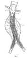
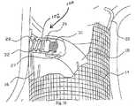
図1は、脈管内移植片送達カテーテル10を、体腔内のガイドワイヤ12の上に配置されているように示す。カテーテル10は、補綴物14(図2参照)を備える。この補綴物は、たとえば、補綴物14の半径方向の拡張によって、目標部位に配置される(図3参照)。補綴物14の部分的または完全な拡張の後、1つ以上のファスナー28(図15および図16参照)がファスナー取り付けアセンブリによって導入され、補綴物14を適所に係留する。
例示説明の目的で、図1は、目標部位を腹部大動脈瘤11の内部にあるものとして示す。この目標部位は、身体内のどこであってもよい。図示した配置において、補綴物14は脈管内移植片という形態をとる。(I. Prosthesis delivery)
FIG. 1 shows an intravascular
For illustrative purposes, FIG. 1 shows the target site as being within the abdominal
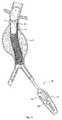
図2は、目標部位における移植片の配備の初期段階を示す。この配備方法は変化し得るが、図示した実施形態において、送達カテーテル10は、可動カバー13を有し、このカバーが、移植片14を覆う。カバー13が近位に引かれると、移植片14は、半径方向に自由に拡張し、それによって拡大し、血管の内壁に接触する。移植片14は、自己拡張性であるように示される。代替的に、移植片14は拡張部材(たとえばバルーンまたは機械的なエキスパンダ)を利用し得る。 FIG. 2 shows the initial stage of graft deployment at the target site. Although this deployment method may vary, in the illustrated embodiment, the
移植片配備のプロセスは、移植片14が脈管内で完全に配備されるか、部分的に配備されるまで続けられる。移植片14は、直線状の形態か分岐した形態かのいずれかの、寸法および構成にされ得る。図3は、完全に配備された直線状の移植片14を示す。図4は、完全に配備された分岐した移植片15を示す。 The process of graft deployment continues until the
(A.補綴物)
移植片14は、支持フレームまたは足場16を望ましくは組み込む。足場16は、弾性であり得、たとえば、形状記憶合金弾性ステンレススチールなどから構成され得る。弾性足場について、拡張は、一般的には、拘束状態から足場を解放し、その足場を移植部位で自己拡張できるようにすることを包含する。図示した配置において、カバー13は、半径方向の拘束として作用する。あるいは、管状カテーテル、送達シースなどを足場16上に配置することが、半径方向に縮小された構成に足場を維持するために作用し得る。この配置において、足場16の自己拡張は、半径方向拘束部材上で後ろに引かれることによって達成され、足場16がより直径の大きい構成になることを可能にする。(A. Prosthesis)
The
代替的に、足場16は、たとえば、内側管、ロッド、カテーテルなどに、足場のいずれかの端部を取り付けることによって、軸方向に伸長された構成で拘束され得る。このことは、足場16を、より直径の短い、伸長された構成に維持する。次いで、この足場16は、自己拡張を可能にするために、このような軸方向の拘束から解放され得る。 Alternatively, the
代替的に、足場16は、他の金属の可鍛性ステンレススチールのような可鍛性材料から形成され得る。このとき、拡張は、半径方向の拡張力を足場内に加えて拡張させることを包含し得る。たとえば、拡張を引き起こすために、足場内で足場送達カテーテルを膨張させることが包含され得る。この配置において、内部移植片の配置および配備は、配備カテーテルと離れているかまたは配備カテーテル中に組み込まれている拡張手段の使用によって達成され得る。このことは、内部移植片が、脈管内に配置され、その脈管内での相対位置をチェックしながら部分的に配備されることを可能にする。この拡張は、バルーンまたは機械的な拡張デバイスのいずれかを介して達成され得る。また、この拡張は、内部移植片に対する血液の力に抵抗することによって、その内部移植片が完全に配備するまで、動脈内の内部移植片の位置を安定させる。 Alternatively, the
移植片14は、広範囲にわたる様々な従来の構成を有し得る。移植片14は、一般的には、足場16によって支持される、ファブリックまたは一部の他の血液半透過性可撓性バリアを備え、ステント構造体の形態を取り得る。このステント構造体は、任意の従来のステント構成を有し得る。従来のステント構成とは、たとえば、ジグザグ、ヘビ状、配備ダイアモンド(expanding diamond)、またはこれらの組み合わせ等である。このステント構造体は、移植片の全長を伸長し得、一部の例においては、移植片のファブリック構成要素よりも長くあり得る。代替的に、このステント構造体は、たとえば補綴物の末端に存在する部分等、補綴物の小さな部分のみをカバーし得る。このステント構造体は、二叉に分かれる血管領域を処置するために構成される場合、3つ以上の末端を有し得る。このような場合とは、たとえば、腸骨動脈中にステント移植片を伸長するときの、腹部大動脈瘤の処置等である。特定の場合において、このステント構造体は、全長、または少なくともその全長の大部分に沿って離間され得る。ここで、個々のステント構造体は互いに直接接続されず、移植片のファブリックまたは他の可撓性構成要素に接続される。 The
移植片足場16またはステント構造体の1つの例示的な実施形態を、図4中の切り取られた領域中に図示する。ここで、ステント構造体は、単純なジグザグパターンの形態であるが、ステントのデザインは、図5に示されるようなより複雑なパターン17を含み得るという点が意図される。図4および図5において、1つのステント構造体のみが移植片中に示されているが、前述のとおり、複数の独立したステント構造体がこの移植片中に組み込まれ得るという点が意図される。 One exemplary embodiment of a
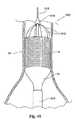
図40は、補綴物14のための補綴物送達カテーテル600の実施形態を示す。この補綴物送達カテーテル600において、ステント構造体16は、たとえば補綴物の末端に存在する部分等、補綴物の一部のみをカバーする。図40に示すように、この補綴物送達カテーテル600(ガイドワイヤ610にわたって配備されて図示されている)は、安定化支柱612のアレイを備え、この安定化支柱612は、補綴物14の末端でステント構造体16に取り外し可能であるように連結される。この連結は、たとえば、カテーテル600中の管腔を通る引きひも(図示せず)を引くことによって解放され得るような縫合によって行われる。この安定化支柱612は、自己拡張ステント構造体16を脈管壁34に対する位置に保持し、この補綴物14の残りの部分は、(送達シース614を引き抜くことによって)配備されている。支柱612は、補綴物が配備する間、脈管を通る血流の力に対して、ステント構造体16(および、したがって補綴物14全体)を保持する。カテーテル600はまた、その遠位端に円錐頭618を備え得、血流を脈管壁に拡散させ、補綴物14の配備の間、この補綴物14を支持するのを補助する。補綴物14の配備の際、支柱612は、縫合を解放するための引きひもを引くことによってステント構造体14から取り外され得、そしてカテーテル600は、送達シース614を通るガイドワイヤ610上を、一緒に引かれる(ステント構造体16から自由にされた支柱612は、送達シース614を通る間にカテーテル600上で折り返される)。 FIG. 40 shows an embodiment of a
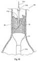
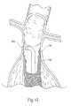
図41は、補綴物14のための補綴物送達カテーテル700の代替実施形態を示す。この補綴物送達カテーテル700において、ステント構造体16は、たとえば補綴物の末端に存在している部分等、補綴物の一部のみをカバーする。図40に示すように、補綴物送達カテーテル700(これも、ガイドワイヤ710上で配備されて示される)は、反転された安定化支柱712のアレイを備え、この支柱712は、たとえば、カテーテル700中の管腔を通る引きひも(図示せず)を引くことによって解放され得るような縫合によって、補綴物14の末端でステント構造体16に取り外し可能であるように接続される。この反転された安定化支柱712は、図40に示される支柱612と同様に、脈管壁34に対する位置に自己拡張ステント構造体16を保持し、補綴物14の残りの部分は、(送達シース714を引くことによって)配備されている。図40におけるカテーテル600のように、カテーテル700はまた、その遠位端に脈管壁に向けて血流を拡散させるための円錐頭718を備え得る。補綴物14が配備する際に、支柱712は、引きひも(図示せず)を引くことによってステント構造体14から取り外され、そしてカテーテル700は、送達シース714を通るガイドワイヤ710上を引かれる(ステント構造体16から自由にされた支柱612は、送達シース614を通る間にカテーテル600上で折り返される)。 FIG. 41 shows an alternative embodiment of a
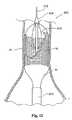
図42は、補綴物14のための補綴物送達カテーテル800の代替実施形態を示し、この中で、ステント構造体16は、たとえば補綴物の末端に存在する部分等、補綴物の一部のみをカバーする。図42に示すように、補綴物送達カテーテル800(これも、ガイドワイヤ810上で配備されて示されている)は、自己拡張安定化バスケット812を備える。この安定化バスケット812は、脈管壁に対する位置に自己拡張ステント構造体16を保持し、補綴物14の残りの部分は、(送達シース814を引くことによって)配備されている。図40のカテーテル600および図41のカテーテル700のように、カテーテル800はまた、脈管壁に向けて血流を拡散させるための円錐頭818をその遠位端に備え得る。補綴物14が配備する際に、安定化バスケットは、カテーテル800がガイドワイヤ810上で引かれるように、送達シース814を通って引くことによって折り畳まれた状態で配置される。 FIG. 42 shows an alternative embodiment of a
記載した全ての実施形態において、ファスナー28を導入する前に補綴物14が完全に配備され、かつ/あるいは補綴物送達カテーテル600、700、または800が目標部位から引き抜かれた場合、ガイドワイヤ610、710、810は、補綴物14のためのファスナー取り付けアセンブリを目標部位へ配備するために連続的に使用され得る。このことについては、次いでより詳細に説明する。代替的に、ファスナー28が適用される時点で補綴物14が完全に配備されていない場合、あるいはいかなる理由であれ、補綴物送達カテーテル600、700、または800を引き抜くことが所望されていない場合、補綴物送達カテーテル600、700、または800、ならびにその各ガイドワイヤ610、710、または810は、補綴物14のためのファスナー取り付けアセンブリが身体の別のアクセスポイントから個々のガイドワイヤを介して目標部位へ導入される間、目標部位に維持され得る。この配置において、補綴物14を配備することおよび/または補綴物送達カテーテル600、700、または800を引き抜くことは、ファスナー28が適用された後に完了され得る。 In all the described embodiments, when the
(II.補綴物の固定)
望ましい実施形態において、管腔内のファスナーの取り付けを可能にするファスナー取り付けアセンブリが提供される。この取り付けアセンブリは、様々に構成され得る。(II. Fixation of prosthesis)
In a preferred embodiment, a fastener attachment assembly is provided that allows attachment of a fastener within a lumen. The mounting assembly can be variously configured.
(A.2つの構成要素のファスナーガイドおよび取り付けアセンブリ)
一配置において、ファスナー取り付けアセンブリは、ファスナーガイドまたは方向付け構成要素18とファスナーアプライア構成要素27とを備える。このガイド構成要素18は、望ましくは、操縦可能または偏向可能な(deflectable)先端部を有し、最初にガイドワイヤ12上で配備される。図示した実施形態において使用する場合、補綴物14を送達および配置するために使用されるガイドワイヤ12は、ファスナーガイド構成要素18を引き続いて配備するために脈管内に留まる。代替的に、ファスナーガイド構成要素18を配備するために、身体の別のアクセスポイントからの別のガイドワイヤが利用され得る。いずれの配置においても、望ましくは、ガイド構成要素18が送達されたガイドワイヤの除去後に、そのガイド構成要素18を介してファスナーアプライア構成要素27が配備される。ファスナーアプライア27は、少なくとも1つのファスナー28と、ファスナー駆動機構100とを備える。ファスナー駆動機構100は、ファスナー28が補綴物14およびその下の脈管壁を貫通し、それによって補綴物14を適所にしっかりと係留するように、ファスナー28を前進させる。(A. Two component fastener guide and mounting assembly)
In one arrangement, the fastener mounting assembly comprises a fastener guide or
(1.ファスナー方向付け構成要素)
図6は、方向付けまたはガイド構成要素18の1つの実施形態を示し、この構成要素18は、ファスナー取り付けアセンブリの一部を形成する。この構成要素18は、閉塞具19の通過を適合する管腔を含む。閉塞具19は、図7に示すように、ガイドワイヤ12上で方向付けデバイス18の送達を可能にするための管腔を含む。一旦所望の位置に配備されると、閉塞具19およびガイドワイヤ12は取り外され、ファスナーアプライア構成要素27を通過させるために中央の管腔を開いたままにする。このことについては後述する。(1. Fastener orientation component)
FIG. 6 shows one embodiment of an orientation or
図示した実施形態(図8参照)において、方向付けデバイス18は、制御アセンブリ21を備える。1つの実施形態において、制御アセンブリ21は、可動ホイールまたは可動レバー22を特徴とする。図9に示すように、可動ホイールまたは可動レバー22は、方向付けデバイス18の遠位先端部23を所望の位置に偏向する従来の様式で内部ステアリングワイヤを操作する。方向付けデバイス18のための制御アセンブリが、機械的、電気的、液圧的、または空気力的に作動され得るという点が意図される。制御アセンブリ21は、閉塞具19(今記載した)およびアプライア構成要素27の通過を可能にする通過管腔を有する。このことについては次いで説明する。 In the illustrated embodiment (see FIG. 8), the directing
(2.ファスナーアプライア構成要素)
図14は、ファスナー取り付けアセンブリの一部を形成するファスナーアプライア構成要素27の一実施形態を示す。図15に示すように、ファスナーアプライア構成要素27は、方向付けデバイス18の中央の管腔を介して、ファスナー28が設置される部位に配備される。(2. Fastener applier components)
FIG. 14 illustrates one embodiment of a
ファスナーアプライア構成要素27(図14参照)の遠位端には、ファスナー駆動機構100が配置されている。図示した実施形態(図14A参照)において、駆動機構100は、担体102に結合されるドライバ29を含む。ドライバ29と担体102との間の結合は、様々な形態をとり得る。様々な形態とは、たとえば、磁石、把持器具、または他の適切な機械的接続である。図14Aに示す実施形態において、ドライバ29および担体102は、単一のユニットとして一体的に接続される。 A
担体102は、選択されたファスナー28を係合するように寸法決めされ、構成される。図14Aにおいて、ファスナーは、図18および図27に示されるタイプのうち、螺旋状ファスナーという形態をとっている。図27に最良に示され、より詳細に以下に記載されるように、図26の螺旋状ファスナー28は、鋭くされたリード先端部142を有する開口コイル148である。ファスナー28の近位端144は、L字型脚部146を備える。L字型脚部146は、望ましくは、このコイル148の内径全体を横切る。すなわち、L字型脚部146は、図27が示すように、コイル148の内径を完全に横切って延びる。L字型脚部146は、ファスナーアプライア27の担体102を係合するように機能し、螺旋状ファスナーを回転させて移植を達成させる。L字型脚部146はまた、螺旋状ファスナーが組織中であまり遠くに貫入するのを防ぐための停止具としても機能する。 The
図14A中の担体102は、スロット180を備える。スロット180は、L字型脚部146を受容してファスナー28を担体102と共に回転させるために接続する。コイル148の巻きは、担体102を取り囲む相補的な内溝32中に収まる。溝32は、ファスナー28の全長またはその長さの一部に沿って配置され得る。 The
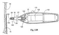
駆動機構100の作動は、当然、様々な方法で達成され得る。たとえば、機械的(すなわち、手動つまり手の力による)方法、電気的方法、液圧的方法、または空気力的方法で達成され得る。図示した実施形態(図14B参照)において、駆動ケーブル30は、ファスナードライバ29をアプライアハンドル108中に備えられる電気モータ106に結合する。駆動ケーブル30は、望ましくは、屈曲および回転の両方を可能にする適切な材料で作製される。モータ106によって駆動されると(後述するとおり、順番に、モータ制御ユニット31の制御下で)、駆動ケーブル30は、ドライバ29、およびそれと共に担体102を回転させる。担体102は、組織中への移植のための螺旋状ファスナー28に回転およびトルクを与える。 The operation of the
図16は、ファスナーアプライア27および方向付けデバイス18の拡大断面図である。図17は、ファスナードライバ29の断面図を伴うファスナーアプライア27の拡大断面図であり、ファスナードライバ29と螺旋状ファスナー28との間の係合を示す。図19は、ファスナー駆動機構100の作動中の、ファスナーアプライア27を示す。駆動機構100の作動(activation)は、駆動シャフト30と、ドライバ29と、担体102と、螺旋状ファスナー28とを、ユニットとして回転させる。この回転は、螺旋状ファスナー28をファスナーアプライアの内溝32内ならびに補綴物14および脈管壁34中に移動させる(図20参照)。図21は、移植片14の脈管壁34への取り付けが完了された螺旋状ファスナー28を図示する。 FIG. 16 is an enlarged cross-sectional view of the
使用の際に、アプライア構成要素27は、方向付け構成要素18を通って前進され、補綴物と接触する。操作者は、制御スイッチ110に接触することによって制御ユニット31を作動させる(図14および14B参照)。この動作は、螺旋状ファスナー28を回転させ、担体102から離し、補綴物14を通して脈管壁34に入らせる。モータ制御ユニット31は、望ましくは、駆動ケーブル30を、各作動コマンドで特定の旋回数、回転させる。これは、機械式計数機または電気式計数機を組み込むことによって達成され得る。 In use, the
ファスナー28の配備によって、ファスナーアプライア27は、方向付けデバイス18を通って回収され、そして別のファスナー28が担体102中に充填される。この方向付けデバイス18は、再配置および安定化され、そしてアプライア27は、再び、方向付けデバイス18を通って補綴物14と接触する方向に前進される。操作者は、再び、制御スイッチ110に接触することによって制御ユニット31を作動させ、別のファスナー28を配備する。このプロセスは、補綴物14の近位端および/または遠位端の両方において、補綴物14が脈管壁34に適切に接続され、そしてその脈管壁にシールされるまで、繰り返される。約2〜約12個のファスナー28が固定をもたらすために補綴物14の各末端において適用され得ることが意図される。ファスナー28は、単一の周囲に間隔をあけられた並びで適用され得るか、または軸方向に整列されるかもしくは周囲に少しずつずらされている個々のファスナーを有する1つより多い並びで適用され得る。 Due to the deployment of
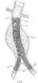
図22は、近位および遠位の両方で脈管壁に取りつけられた移植片補綴物の斜視図を示す。本発明は、大動脈および他の分枝脈管内の直線状移植片および二叉に分かれた移植片の両方の取りつけのために使用され得ることが意図される。 FIG. 22 shows a perspective view of a graft prosthesis attached to the vessel wall both proximally and distally. It is contemplated that the present invention can be used for the attachment of both straight and bifurcated grafts in the aorta and other branch vessels.
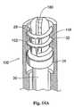
駆動機構100の代替の実施形態を、図25Aおよび図25Bに示す。この実施形態において、ドライバ29は、担体150に結合され、この担体150は、図28Aにも示されるように、螺旋状ファスナー28それ自体の一部を形成する。図28Aに示されるように、螺旋状ファスナー28は、図27に示されるファスナーと同様の、鋭くされたリード先端部142を有する開口コイル148である。ファスナー28の近位端144は、担体150を備える。 An alternative embodiment of the
担体150は、スロット182を備える。スロット182は、ドライバ29上の駆動フランジ184に係合し(図25A参照)、移植プロセスの間、ドライバ29の回転を、螺旋状ファスナー28の回転に与える。図27に示されるファスナーのL型脚部のように、担体150はまた、螺旋状ファスナーが離れすぎて組織に貫入しないことを防止するための停止具としても作用する。 The
担体150とドライバ29との間の結合係合は、様々な様式において達成され得る。たとえば、分離グラスパーまたは分離グリッパー、磁気結合、または任意の他の適切な機械的結合手段によって達成され得る。図示した実施形態において、ドライバ29は、磁性材料から作製され、担体150は、磁性材料の方に磁気的に引き寄せられる材料から作製される。当然のことながら、磁性材料および磁気的に誘引される材料の逆の配置が使用され得る。 Coupling engagement between the
この配置において、駆動ケーブル30とモータ106との間のモータ結合132は、モータ106との駆動結合を分断せずにモータケーブル30の軸方向の移動(図25Aおよび図25Bにおいて左および右)に適合する。補綴物14と接触するアプライアデバイス27の遠位先端部(図25A参照)で、操作者は、制御スイッチ110に接触することによって制御ユニット31を作動させる。制御ユニット31は、モータ106が駆動ケーブル30を回転させ、回転をドライバ29および磁気結合螺旋状ファスナー28に与えることを命令する。この作用は、磁気的に結合された螺旋状ファスナー28が、補綴物14および脈管壁34へと回転されるようにする(図25B参照)。磁気結合によって、ファスナー28は、図25Bの左に配備される場合、ドライバ29が、担体150と縦一列に並んで(図25Bにおいても左に)移動するように配備される。担体150とドライバ29との間の磁気結合に起因して、操作者は、ドライバ29から担体150(およびそれと共にファスナー28)を分断する故意の分離力を働かせなければならない。この配置は、ファスナー28の不注意の解離を防止する。 In this arrangement, the
先に記載したように、ファスナー28を配備させると、アプライア構成要素27は、方向付けデバイス18によって回収され、別のファスナー28が、ドライバ29に磁気的に結合される。方向付け構成要素18は、再配置され、安定化され、アプライア構成要素27は方向付け構成要素18によって再度前進され、補綴物14と接触される。操作者は、再度、制御スイッチ110に接触することによって制御ユニット31を作動させ、別のファスナー28を配備する。このプロセスは、補綴物14が、脈管壁34に適切に取り付けられ、密着されるまで、補綴物14の近位端および/または遠位端の両方で繰り返される。 As previously described, once the
上記で示したように、アプライア構成要素27の外径は、方向付け構成要素18の管腔を通過するように、望ましく寸法決めされ、構成される。方向付け構成要素18は、適切な操縦可能ガイドカテーテルの形態をとり得、アプライア構成要素27を所望の位置に方向付けする。また上述のように、アプライア構成要素27は、望ましくは、一度に1つのファスナー28を移植するように(いわゆる「シングルファイヤ」アプローチ)構成される。このことは、設計の複雑性を低減し、蛇行性構造を通してアプライア27のアクセスを受け入れるため、望ましいと考えられる。単一のファスナーを備えるファスナーアプライア構成要素27は、複数のファスナーを保有するファスナーアプライアよりも、低いプロフィールを有し得、効果的であり得、外傷性が低くあり得る。なお、代替の実施形態において、アプライア構成要素27は、所望の場合、複数のファスナーを備えるように構成され得る。さらに、ファスナーアプライア27は、周囲において好ましく離間された、上記のスペースパターンにおいて、複数のファスナーを同時に配備し得る。
(3.力の分解(Force Resoluton))
アプライア構成要素27を用いて組織内へファスナー28を貫入および移植するには、アプライア構成要素27が補綴物14および脈管壁34において、あるいはその近傍で、移植力を加える必要がある。図示した実施形態において、アプライア構成要素27は、螺旋状ファスナーを移植するための駆動式部材を備える。しかしながら、アプライア構成要素27は、実際には、たとえば超音波、レーザ、または衝撃という概念を用いて移植力を加える任意の作動される部材を備えることができる。As indicated above, the outer diameter of the
(3. Force Resolution)
In order to use the
移植力が生じる詳細な方法とは無関係に、アプライア構成要素27の移植力は、望ましくは分解され、何らかの方法で、部分的な安定を提供し、移植部位に対してアプライア構成要素27の意図しない移動を抑える。換言すれば、分解力は、望ましくは、アプライア構成要素27の移植力に反作用および/または対抗するために加えられる。脈管内腔(vessel lumen)(またはその他の中空の身体器官)自体における移植力のうちの一部または全部または実質的な部分を分解することが望ましい。また、移植位置に可能な限り近いことが好ましい。 Regardless of the detailed manner in which the grafting force occurs, the grafting force of the
方向付け構成要素18の管状体、およびファスナーアプライア構成要素27のシャフトは、脈管内腔またはその他の中空の身体器官における移植力のうちの一部または全て、あるいは少なくとも一部分を分解するために十分な柱強度を有するように寸法決めされ得、構成され得る。それに加えて、または代替的に、方向付け構成要素18および/またはファスナーアプライア構成要素27は、ファスナーを移植するファスナーアプライア構成要素27の駆動式部材、あるいはその近傍に反作用力を加えるための安定化手段20を含むことができる。 The tubular body of the directing
図示した実施形態は、安定化手段20の様々な代替実施形態を示す。図8および図9に示すように、安定化手段20は、接触している組織に対する方向付け要素18上でバネ荷重アームという形態をとる。この配置において、バネ荷重式の安定化手段20は、閉塞具19およびガイドワイヤ12が方向付け構成要素18から取り外されたときに(図8参照)配備されるように配置される。図10および図11に示す代替実施形態において、安定化手段20は、組織に接触する方向付け構成要素18上で、可動支柱アセンブリ24という形態をとる。この代替実施形態において、可動支柱アセンブリ24は、たとえば、制御アセンブリ(図11参照)上のレバー25を介して作動され得る。両方の実施形態において(図7および図10)安定化デバイス20は方向付け構成要素18の遠位端にある。図12に示す代替実施形態において、安定化手段20は、方向付け構成要素18の先端部近傍に配置された拡張可能部材26という形態をとる。この代替配置において(図13参照)、拡張可能部材26は、たとえば、制御アセンブリ21上のレバー25を介して作動され得る。しかしながら、このタイプの安定化手段20は膨張することもでき得るということが意図される。別の代替実施形態(図43参照)において、安定化手段20は、方向付け構成要素18および/またはファスナーアプライア構成要素27が備える、ファスナーを移植する前に中空の身体器官、脈管あるいは補綴物の壁部を把持および/または係留するための部材200を含む。把持手段または係留手段200は、貫通する針および/またはフック、または突起を含むことができる。これらは、ファスナーを移植する前に、制御アセンブリ等によって配備される。 The illustrated embodiment shows various alternative embodiments of the stabilizing
全ての実施形態において、安定化手段20は、集中的または分散的に脈管内に方向付け要素18を安定化するために用いられ得る。 In all embodiments, the stabilizing means 20 can be used to stabilize the directing
当然、安定化手段20のこれらの代替的な形態は、方向付け構成要素18と連携され得るのと同様の方法で、ファスナーアプライア27と連携され得る。あるいは、同様の機能を有する安定化機構の、その他の一部の形態をとる。さらに別の実施形態において、安定化手段20は、方向付け構成要素18および/またはファスナーアプライア構成要素27と協働して用いられる独立した安定化デバイスという形態をとることができる。この配置において、独立した安定化デバイスは、上記の安定化デバイスのうちの任意の代替的な安定化デバイスという形態、あるいは、操縦可能または操縦不可能な、その他の一部の安定化機構という形態をとることができる。 Of course, these alternative forms of stabilization means 20 can be associated with the
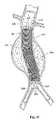
たとえば(図44Aおよび図44B参照)、ファスナーアプライア27は、拡張可能なバスケット202またはバスケット状の構造体を遠位端に担うことができる。前述したように、バスケット構造体202は、ファスナー駆動機構100を取り囲んでいる。バスケット構造体202は、ファスナー駆動機構100に関して、低いプロファイルで、一般的に折りたたまれた状態(図44Aに示す)から、拡張されたプロファイル状態(図44Bに示す)まで、動作可能である。 For example (see FIGS. 44A and 44B), the
一般的に折りたたまれた状態において、ファスナーアプライア27は、脈管を介して移植片14の近傍まで配備され得る。図44Aは、自己拡張式の足場16を含んで移植片14を示す。一般的に折りたたまれた状態において、ファスナーアプライア27は、脈管内を介して目標となる移植片部位まで、その低いプロファイル状態にて配備され得る。ファスナーアプライア27は、自動的に、あるいは、操縦可能または操縦不可能な、方向付け構成要素18や適切なガイドシースと連携して配備し得る。 In the generally folded state, the
移植片部位(図44B参照)に位置する場合、バスケット構造体202は移植片14と接触するように拡張可能である(たとえば、適切な押し引きの制御機構によって)。前述したとおり、ファスナーアプライア27は、移植片14に接触するように拡張されたバスケット構造体202内で操縦され得、ファスナー28を配備するように操作され得る。バスケット構造体202は、移植力のうちの少なくとも一部を分解して、部分的な安定を提供し、ファスナーアプライア27の意図しない移動を抑える。 When located at the graft site (see FIG. 44B), the
これらの全ての代替実施形態において、安定化手段20は、脈管上の位置に対して実質的に等しくかつ対抗する反作用力を脈管内(図45参照)に加えるために機能する。望ましくは、脈管上の位置とは一般的に移植部位に対向の位置である。連携された方向付け構成要素18および/またはファスナーアプライア27の柱の強度は、安定化手段20とも協働し、移植部位における管腔内移植力を分解するためにも機能することができる。 In all these alternative embodiments, the stabilizing means 20 functions to apply a reaction force in the vessel (see FIG. 45) that is substantially equal and opposed to the location on the vessel. Desirably, the position on the vessel is generally the position opposite the implantation site. The strength of the associated
ガイド構成要素18および/またはファスナーアプライア構成要素27が提供する、力分解機能は、アプライア構成要素27の組織貫通および移植力を、反作用するか、対抗するか、あるいはそれ以外の方法で分解するように機能する。それによって、力分解機能は移植部位に対してアプライア構成要素27の移動をも抑え、それによって安定的で信頼性のある管腔内の(または器官内の)固定プラットフォームを可能にする。
(4.補綴物/組織接触感知)
ファスナーアプライア構成要素27は、望ましくは、アプライア構成要素27の先端部が、補綴物または組織表面と所望される程度の接触になるまで、モータ106の作動を防止する機能を組込む。これは、ファスナー28の不注意の発射および/またはファスナー28の離脱を防止する。この機能は、たとえば、設計において、機械的または電気的のいずれかである接触センサまたは力センサを使用して、実行され得る。The force-resolving function provided by the
(4. Prosthesis / tissue contact sensing)
The
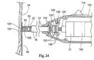
ファスナーアプライア構成要素27が、図14A、図14Bおよび図14Cに示される型である場合(図23および図24参照)、接触感知機能または力感知機能は、たとえば、接触力を伝達するための担体102の遠位先端部120を使用し得る。この力は、たとえば、ファスナーアプライアハンドル108内に位置する力または接触感知スイッチ122に伝達され得る。この配置において、スイッチ122は、アクチュエータスイッチ110と制御ユニット31との間の電気回路の一部であり得る。 When the
図示した実施形態において、スイッチ122は、静止スイッチ要素128(ハンドル108の内部に結合される)および可動性スイッチ要素130(駆動ケーブル31によって保持される)を備える。この配置において、駆動ケーブル30とモータ106との間のモータ結合132は、モータ106との駆動結合を分断することなく、モータケーブル30の軸方向移動(図23および図24において左および右)に適合する。駆動ケーブル30は、ベアリング134によって、可動性スイッチ要素130に連結され、その結果、スイッチ要素130は、駆動ケーブル30の移動に応答して移動する。静止スイッチ要素128は、移動性駆動ケーブル30に結合されず、これは、スイッチ要素130をスライド可能に通過する。 In the illustrated embodiment, the
この配置によって、駆動ケーブル30の軸方向移動は、スイッチ要素128に関してスイッチ要素130を移動させる。より具体的には、駆動ケーブル30の図23における左への移動は、スイッチ要素130を、スイッチ要素128から離れて左に移動させる。逆に、駆動ケーブル30の図23における右への移動は、スイッチ要素130を、スイッチ要素128の方へ右に移動させる。 With this arrangement, axial movement of the
バネ126は、通常、スイッチ要素128と130から離れて偏らされ、電気的に開いた状態を備える。この状態において、作動スイッチ110の操作は、制御ユニット31を作動させるようには働かない。なぜならば、電気的開放スイッチ122が、モータ制御ユニット31に対する作動シグナルの伝達を分断するからである。スイッチ要素128および130が、電気的に開いた状態にある場合、駆動ケーブル30は、ファスナーアプライア27の遠位先端部124を越えて担体先端部120を位置決めするように、左に移動される。従って、担体先端部120は、アプライア先端部124の前で補綴物14または組織と接触される。 The
担体先端部120は、バネ126を圧縮するのに十分な力で、補綴物または組織の表面と接触する場合、駆動ケーブル30は、バネの偏位力に対抗して、図23の右へ移動される。これは、スイッチ要素130を右に移動する。最終的には、スイッチ要素128と130との間の接触は、図24に示すように生じる。この接触は、電気的に閉じた状態を確立する。この状態において、作動スイッチ110の操作は、制御ユニット31を作動するように作用する。図23および図24に示されるように、接触スクリュー136は、スイッチ要素128および130を閉じるために必要な移動の大きさを調整するように提供され得る。 When the
接触力の除去の際、または十分な接触力の非存在下において、バネ126は、スイッチ要素128および130を電気的に開いた状態の方へ駆動する、担体102の遠位先端部は、アプライア27の遠位先端部を越えて遠位に位置される。 Upon removal of the contact force, or in the absence of sufficient contact force, the
担体先端部120のスイッチ122への並進移動が、駆動ケーブル30の全長に沿って起こる必要がないという点が理解されるべきである。たとえば、スイッチ122は、担体102とドライバ29との間の並進空間に位置され得る。この配置において、駆動ケーブル30に結合されるドライバ29は、軸方向の移動に適合する必要はない。代わりに、補綴物14との接触に応答しての担体102のドライバ29の方への相対的移動は、(たとえば、図25Aおよび図25Bに示されるものと類似のスロットおよびフランジ接続によって)担体10をドライバ29と機械的に結合させ、一方、アクチュエータスイッチ110とモータ制御ユニット31との間の回路に電圧を加えるためにスイッチ122を再び閉じる。 It should be understood that translational movement of the
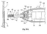
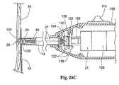
ファスナーアプライア構成要素27が、図25Aおよび図25Bに示すタイプのものである場合(図26A、図26B、および図26C参照)、接触または力感知機能は、たとえば、担体150’(担体150’は、図28Bに示される)、ドライバ29および駆動ケーブル30における中央通路192をスライド可能に通過する、力感知ロッド190を使用し得る。このロッド190は、可動性スイッチ要素130に結合される。この実施形態において、スイッチ要素130は、駆動ケーブル30に関して左および右に並進し、これは、スイッチ要素130内のベアリング134において回転する。 If the
先の実施形態のように、バネ126は、通常、スイッチ要素128および130を離して偏位させ、これは、電気的に開いた状態を備える。スイッチ要素128および130が、電気的に開いた状態にある場合、力感知ロッド190は、ファスナーアプライア27の遠位先端部124を超えて左に移動される。従って、力感知ロッド190は、補綴物14またはアプライア先端部124の前の足場構造16と接触する。 As in the previous embodiment, the
ロッド190が、バネ126を圧縮するのに十分な力で補綴物または足場構造の表面と接触する場合、ロッド190は、バネ126の偏位力に対抗して、図26Aの右へ移動される。これは、スイッチ要素130を右へ移動する。最終的には、スイッチ要素128と130との間の接触は、図26Bに示すように生じる。この接触は、電気的に閉じた状態を確立する。この状態において、スイッチ110を作動する操作は、制御ユニット31を作動するように働く。この作用によって、螺旋状ファスナー28が、足場構造中16に、そして脈管壁34中に回転して入る(図26C参照)。ファスナー28が配備される場合、ドライバ29と担体150’との間の磁気結合に起因して、ドライバ29は、結合された担体150’と縦一列に並んで図26Bの左に移動される。また、担体150とドライバ29との間の磁気結合のため、操作者は、ドライバ29から担体150(および、それと共にファスナー28)を解離するように分離力を働かせなければならない。前に記載されるように、この配置は、ファスナー28の不注意の解離を防止する。接触ネジ136は、スイッチ要素128および130を近づけるために必要とされる移動の大きさを調整するように備えられ得る。 When
接触力の除去の際、または十分な接触力の非存在下で、バネ126は、スイッチ要素128および130を電気的に開いた状態の方へ推進し、ロッド190の先端部を、アプライア27の遠位先端部124を越えて移動させる。 Upon removal of the contact force, or in the absence of sufficient contact force, the
先ほど説明した接触感知配置または力感知配置はまた、操作者に対して可聴の出力および/または可視の出力を生成し、アプライアデバイス27と補綴物または組織との間の十分な接触力が、存在することを示す。 The previously described contact sensing or force sensing arrangement also produces an audible and / or visible output for the operator, and there is sufficient contact force between the
(B.角度を付けた構成要素ファスナーガイドおよび取り付けアセンブリ)
別の配置において(図29参照)、ファスナー取り付けアセンブリは、単一の角度を付けたファスナーガイドおよびアプライア構成要素160を備える。この配置において、構成要素160は、補綴物または組織に関して垂直の位置にまたは垂直に近い位置にファスナー28を保持する担体164を配置するファスナー駆動機構162を備える。この構成は、前に記載された、ファスナー構成要素27のための、分離された操縦性ガイド構成要素18に対する必要性を排除する。(B. Angled component fastener guide and mounting assembly)
In another arrangement (see FIG. 29), the fastener mounting assembly comprises a single angled fastener guide and
駆動機構162は、変化し得る。示された実施形態において(図29に示される)、機構162は、駆動ケーブル30に連結された駆動ギヤ168を備える。駆動ギヤ168は、トランスファーギヤすなわちピニオンギヤ170と作動可能なようにかみ合い、この駆動ギヤ168は、担体164に接続される。駆動ギヤ168およびピニオンギヤ170の回転軸は、約90°オフセットされており、その結果、脈管軸に沿った駆動ケーブル30の回転は、脈管壁にほぼ垂直な担体164の回転に移される。ファスナーガイドおよびアプライア構成成分160は、種々の方法で(たとえば、外部バネ荷重式の支柱などを使用することによって(上で議論される方向付け構成要素18と関連して示される場合)、または拡張可能部材166の使用によって(図29に示されるように))脈管内に位置決めされ、安定化され得る。拡張部材166は、バルーンまたは機械的拡張デバイスのいずれかを備え得る。拡張部材166は、補綴物が固定され得るまで、血液の力に抵抗することによって、補綴物ならびにファスナーガイドおよび脈管内のアプライア構成要素160の両方の位置を安定化する。 The
図30に示すように、ファスナーガイドおよびアプライア構成要素160は、必要な場合、駆動ケーブル30と担体164との間に角度を付けた配備(この角度は、90°よりいくらか低い)を提供し、脈管壁に対して垂直の接触位置への担体の層内操作を補助する。図31に示すように、ファスナーガイドおよびアプライア構成要素160は、所望される場合、駆動ケーブル30と担体164とのあいだで接合され得る。担体164を、目標部位への配備のための第1のほぼまっすぐな位置(図31において点線で示す)から、脈管壁に対して接触する担体164の配置のための第2の接合位置(図31において実線で示す)まで移動する場合、この配置において、遠隔制御機構が所望される。 As shown in FIG. 30, the fastener guide and
(III.ファスナー)
以上に図示説明したように、ファスナー28の導入は、代表的には、補綴物14が、最初に配置された後、作用する。すなわち、補綴物14の初期配置は、自己拡張またはバルーン拡張によって達成され、その後に、補綴物14は、複数の個々のファスナーの導入によって適所に固定または係留される。ファスナー28は、補綴物14のファブリックを介してのみ(すなわち、足場構造を避けること)配置され得る。あるいは、ファスナー28は、足場構造そのものの部分にそこを通して導入され得る。補綴物14は、予備形成されたレセプタクル、アパーチャまたはグロメットを備え得、これらは、特にファスナーを受け入れるように構成される。ファスナー28は、ファブリックを介して、および足場構造を介しての両方で、導入され得る。ファスナーは、単独に(すなわち一度に1つずつ)、補綴物14の内部壁を超えて周囲に空間を空けたパターンで、導入され得る。(III. Fastener)
As illustrated and described above, the introduction of the
例示的な実施形態において、ファスナー28は、螺旋状ファスナーであり、その結果、これらは、回転し得、補綴物14および脈管壁に「ねじ込まれ」得る。螺旋状ファスナー28(図27、図28A、および図28B参照)に対して所望される構成は、開口コイル148であり、これは、コイルバネに非常に類似する。この構成は、ファスナー28が、より大きな領域の組織を捕捉することを可能にし、このことによって、組織の壊死を導き得る組織圧縮にかけずに、従来のステープルより有意に大きな保持力を生じる。 In the exemplary embodiment,
図27、図28A、および図28Bが示すように、螺旋状ファスナー28のリーディング先端部142は、望ましく鋭く、このリーディング先端部142を、動脈壁および/または石灰化組織に貫入させる。この遠位先端部142は、組織を通る螺旋経路を切断するように鋭くされ得るか、または切断せずに組織に貫入するように一点にまで鋭くされ得る。 As shown in FIGS. 27, 28A, and 28B, the leading
ファスナーの近位端144は、2つの設計機能を供する。第1の機能は、ファスナーアプライア27の担体102に係合することであり、このファスナーアプライアは、移植プロセスの間、螺旋状ファスナーを回転する。第2の機能は、螺旋状ファスナーが組織のあまり遠くに貫入しないようにする停止具として作用することである。 The
1つの実施形態において(図27参照)、螺旋状ファスナー28の近位端144は、コイル148のL型脚部146を備え、これは、ファスナー直径を横切る。コイル148の脚部146は、完全に直径を横断し、ファスナーが開口コイルではないようにし、そして組織への貫入の深さを制御する。さらに、コイル148の脚部146は、以前のコイルに結合され、全体の構造を強化し得、そして、より安定な駆動結合点をファスナーアプライアに提供し得る。この結合は、溶接、接着または任意の他の適切な手段によって達成され得る。 In one embodiment (see FIG. 27), the
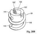
代替的に、(図28Aおよび図28Bに示されるように)、ファスナー28の近位端144は、分離キャップまたは担体150もしくは150’を組み込み得、これは、図27においてコイル148の脚部146と同じ機能を提供する。担体150または150’は、ファスナーアプライア駆動機構100に連結するいくつかの方法を特徴とし得る。これらは、分離グラスパーもしくは分離グリッパー、磁気結合(前記のような)、または任意の他の適切な機械的結合手段を備える。図28Aおよび図28Bにおいて、担体150および150’は、スロット180および182’を備え、駆動フランジ(前記のような)とかみ合う。また前記されるように、磁気結合は、担体150および150’と対応する駆動部材との間に与えられ、使用中の不注意による分離を防止する。 Alternatively (as shown in FIGS. 28A and 28B), the
図28Bにおいて、担体150’はまた、図26A、図26B、および図26Cに示される接触/力感知ロッド190を保持するための通路152を備える。 In FIG. 28B, the carrier 150 'also includes a passage 152 for holding the contact /
図27、図28A、および図28Bに示すファスナー28は、ステンレススチールまたは他のタイプの移植可能な金属から作製され得るが、上記におけるファスナーは、移植可能なポリマーから作製され得るか、または生体分解性ポリマーもしくはこれらの全ての材料の組み合わせから作製され得るということもまた構想される。望ましくは、ファスナー28は、2ターンと10ターンとの間を有し、1mm〜10mmの長さである。個々のコイル間の間隔は、0.25mm〜3mmである。ファスナー28の直径は、1mm〜6mmである。 The
(IV.一体型ファスナーアセンブリを用いる補綴物)
図32は、少なくとも1つの一体型ファスナーアセンブリ502を備える補綴物500を示す。図32は、目標の管腔内領域、特に、腹部大動脈瘤504内に配備された補綴物500を示す。補綴物500は、身体の他の場所に配備され得る。(IV. Prosthesis using integral fastener assembly)
FIG. 32 shows a
補綴物500は、望ましくは、前に記載されたように、支持フレームまたは足場504によって保持される構造材料などを備える。足場504は、たとえば、シースからの配備の間に半径方向に自己拡張する弾性材料、またはバルーンもしくは機械的な拡張デバイスによって、足場内に適用される半径方向での拡張力に応じて半径方向に拡張する、可鍛性の材料から作製され得る。 The
目標領域における補綴物500の配備に続いて、補綴物500上の一体型ファスナーアセンブリ502を操作して、脈管壁に補綴物500を係留する。示された実施形態において、補綴物500は、補綴物500の各端部領域において1つずつ、2つの一体型ファスナーアセンブリ502を保持する。 Following deployment of the
図示した実施形態において、各ファスナーアセンブリ502は、それぞれの端部領域において、補強フランジ区域506に包埋される。各ファスナーアセンブリ502は、フランジ506の円周に間隔をあけてファスナー508のアレイを備える。アレイにおけるファスナー508の数は、たとえば、各フランジ区域506に対して約2から約12のファスナーで変化し得る。アレイの形状はまた、たとえば、円周状アレイで変化し得、ファスナー508も同様に、軸方向に間隔をあけ得る。 In the illustrated embodiment, each
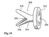
ファスナー508は、金属材料またはプラスチック材料から形成され得、そして種々に構成され得る。示された実施形態において、各ファスナー508は、ディスク形状ヘッド512および2つの翼516および518へ二又状になる幹部514を備え、これらは、プラスチック材料または形状記憶材料の蝶番領域520によって結合される。蝶番領域520の材料は、翼516および518を拡張した間隔のあいた状態に偏らせる(図34に示すように)弾性記憶材料で形成される。 The
各ファスナー508は、フランジ区域506上のグロメット510内に保持される(図35参照)。蝶番領域520が、グロメット510内に制限される場合(図35参照)、翼516および518は、隣接した閉じた状態で弾性記憶材料に対して保持される。ヘッド512(図35参照)に対する押し付け力または打ち抜き力の適用に応答して、翼516および518は、グロメット510から隣接する脈管壁にそこを通って閉じた状態で進められる(図36参照)。連続した進行の際に、蝶番領域520は、グロメット510(図37参照)の制限から解放される。その結果、翼516および518は、それらの通常の広がった状態に弾性的に伸びる。 Each
この配置において、管腔内器具522(図33参照)は、補綴物500へと配備され、所定のファスナー508のヘッド512に対して押し付け力または打ち抜き力を作動させる。示された実施形態において、器具522は、その遠位端に打ち抜き部材526を保有するカテーテル524を備える。所望の配置において、カテーテル524の遠位端は、操縦可能であり、所定のファスナー508の打ち抜き部材526とヘッド512との間の点接触を確立するのに役立つ。ヘッド512は、凹部528を備え、使用の間にヘッド512に関して打ち抜き部材526の先端部を受け入れそして安定化させ得る(図34参照)。 In this arrangement, an intraluminal device 522 (see FIG. 33) is deployed on the
使用の際には、打ち抜き部材526を操作して、選択されたファスナーヘッド512に対して押し付け力または打ち抜き力を適用する。図35および図36が示すように、打ち抜き部材526による打ち抜き力の適用は、脈管壁34の近側に対して翼516および518を押し付ける。翼516および518は、依然としてそれらの閉じた状態である。なぜなら、蝶番領域520が、依然としてグロメット510内に制限されているためである。閉じた翼516および518は、脈管壁の遠側に進むにつれて組織に貫入する閉塞具を形成する。蝶番領域520が、グロメット510(図37)から解放されるにつれて、翼516および518は、脈管の遠側に対してそれらの拡張した間隔のあいた状態に弾性的に戻る。打ち抜き部材526(図38参照)の取り除きの際に、ヘッド512ならびに拡張して間隔の空いた翼516および518は、脈管壁内でのそれらの相互に対向した状態のままであり、脈管壁に対して補綴物500を固定する。使用に際して、医師は、各ファスナー508に対して連続して打ち抜き部材526を位置決めおよび操作し、脈管壁に対する補綴物500の係留を完了させる。 In use, the punching
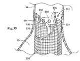
一実施形態において(図39参照)、各ファスナー508は、ヘッド512に対して解放可能に連結されたトラッキングワイヤ530を備え得る。トラッキングワイヤ530は、脈管の外側の接近のために身体の外側のヘッド512から延びる。この配置において、打ち抜き部材526は、トラッキングワイヤ530の通過に適応するような管腔を備える。トラッキングワイヤ530は、それぞれのファスナー508への管腔内通路に打ち抜き部材526を誘導する。打ち抜き部材526を操作して、ファスナー508を脈管壁へと駆動させた後に、打ち抜き部材526は、トラッキングワイヤ530上で引き出され得る。トラッキングワイヤ530は、たとえば、トラッキングワイヤ530に対して適度の引き込み力を適用することによって、現在固定されているヘッド512から解放され得る。次いで、トラッキングワイヤ530が引き込み得る。続いて、打ち抜き部材526は、所望の程度の係留が、達成されるまで、ファスナー508のうちの別の1つとの相互作用のために、別のトラッキングワイヤ530上で誘導される。 In one embodiment (see FIG. 39), each
代替的な実施形態において、補綴物500上の一体型ファスナーアセンブリ502を使用して、永久的な係留技術が、実行される間、補綴物500を適所に一時的に仮留し得る。たとえば、この配置において、一体型ファスナーアセンブリ502を使用して、所望の位置に補綴物500を一時的に保持した後に、分離螺旋状ファスナー28は、前に記載の様式で配備し、脈管壁に対して補綴物500を永久的に係留する。 In an alternative embodiment, the
本明細書に記載の好ましい実施形態の構成要素および/または特徴は、共に、または別個に使用され得、示した方法およびデバイスは、全体または一部が組み合わされ得るか、あるいは改変され得るということが理解されよう。方向付けデバイス、つまりファスナーアプライアおよび螺旋状ファスナーの構成要素は、互いが、たとえば、オフセット、二軸等に方向付けられ得ることが意図される。さらに、種々の実施形態が、本明細書に記載されていないさらなる手順(たとえば、脈管内そして一般的に身体内での脈管外傷、動脈解離、人工心臓弁装着および他の補綴物デバイスの装着)において使用され得ることが理解される。 The components and / or features of the preferred embodiments described herein may be used together or separately, and the methods and devices shown may be combined in whole or in part or modified. Will be understood. It is contemplated that the components of the orientation device, i.e., fastener applier and helical fastener, may be oriented with respect to each other, e.g., offset, biaxial, etc. In addition, various embodiments provide additional procedures not described herein (eg, vascular trauma, arterial dissection, prosthetic heart valve attachment, and other prosthetic device attachments within the vessel and generally within the body. It is understood that
完全な開示を示す目的のため、また説明および明瞭性のために、本発明の好ましい実施形態を詳細に上述してある。当業者は、本開示の範囲および精神内の他の改変を構想する。 For the purpose of providing a complete disclosure, and for the sake of explanation and clarity, preferred embodiments of the invention have been described above in detail. Those skilled in the art will envision other modifications within the scope and spirit of the present disclosure.
Claims (1)
Translated fromJapaneseApplications Claiming Priority (1)
| Application Number | Priority Date | Filing Date | Title |
|---|---|---|---|
| US10/669,881US7491232B2 (en) | 1998-09-18 | 2003-09-24 | Catheter-based fastener implantation apparatus and methods with implantation force resolution |
Related Parent Applications (1)
| Application Number | Title | Priority Date | Filing Date |
|---|---|---|---|
| JP2006528036ADivisionJP4465359B2 (en) | 2003-09-24 | 2004-09-10 | Apparatus and method for implanting catheter-based fasteners using graft force degradation |
Publications (1)
| Publication Number | Publication Date |
|---|---|
| JP2010051786Atrue JP2010051786A (en) | 2010-03-11 |
Family
ID=34421985
Family Applications (3)
| Application Number | Title | Priority Date | Filing Date |
|---|---|---|---|
| JP2006528036AExpired - Fee RelatedJP4465359B2 (en) | 2003-09-24 | 2004-09-10 | Apparatus and method for implanting catheter-based fasteners using graft force degradation |
| JP2008323290AWithdrawnJP2009112827A (en) | 2003-09-24 | 2008-12-19 | Apparatus and method for transplanting fastener on catheter basis using resolution of transplanting force |
| JP2009122573APendingJP2010051786A (en) | 2003-09-24 | 2009-05-20 | Apparatus and method for transplanting fastener of catheter base using resolution of transplanting force |
Family Applications Before (2)
| Application Number | Title | Priority Date | Filing Date |
|---|---|---|---|
| JP2006528036AExpired - Fee RelatedJP4465359B2 (en) | 2003-09-24 | 2004-09-10 | Apparatus and method for implanting catheter-based fasteners using graft force degradation |
| JP2008323290AWithdrawnJP2009112827A (en) | 2003-09-24 | 2008-12-19 | Apparatus and method for transplanting fastener on catheter basis using resolution of transplanting force |
Country Status (7)
| Country | Link |
|---|---|
| US (7) | US7491232B2 (en) |
| EP (1) | EP1675528B1 (en) |
| JP (3) | JP4465359B2 (en) |
| CN (1) | CN1856280B (en) |
| AU (1) | AU2004277897B2 (en) |
| CA (1) | CA2539585C (en) |
| WO (1) | WO2005032333A2 (en) |
Cited By (8)
| Publication number | Priority date | Publication date | Assignee | Title |
|---|---|---|---|---|
| US8685044B2 (en) | 2001-11-28 | 2014-04-01 | Aptus Endosystems, Inc. | Systems and methods for attaching a prosthesis with a body lumen or hollow organ |
| US8690897B2 (en) | 2001-11-28 | 2014-04-08 | Aptus Endosystems, Inc. | Devices, systems, and methods for prosthesis delivery and implantation, including the use of a fastener tool |
| US9023065B2 (en) | 2001-11-28 | 2015-05-05 | Aptus Endosystems, Inc. | Devices, systems, and methods for supporting tissue and/or structures within a hollow body organ |
| US9320589B2 (en) | 2001-11-28 | 2016-04-26 | Medtronic Vascular, Inc. | Endovascular aneurysm repair system |
| US9320503B2 (en) | 2001-11-28 | 2016-04-26 | Medtronic Vascular, Inc. | Devices, system, and methods for guiding an operative tool into an interior body region |
| US9968353B2 (en) | 2001-06-04 | 2018-05-15 | Medtronic Vascular, Inc. | Catheter based fastener implantation apparatus and methods |
| US10098770B2 (en) | 2001-11-28 | 2018-10-16 | Medtronic Vascular, Inc. | Endovascular aneurysm devices, systems, and methods |
| US10194905B2 (en) | 2001-11-28 | 2019-02-05 | Medtronic Vascular, Inc. | Devices, systems, and methods for endovascular staple and/or prosthesis delivery and implantation |
Families Citing this family (611)
| Publication number | Priority date | Publication date | Assignee | Title |
|---|---|---|---|---|
| EP1309289A2 (en) | 2000-08-18 | 2003-05-14 | Atritech, Inc. | Expandable implant devices for filtering blood flow from atrial appendages |
| US7637932B2 (en)* | 2001-11-28 | 2009-12-29 | Aptus Endosystems, Inc. | Devices, systems, and methods for prosthesis delivery and implantation |
| US20090112303A1 (en)* | 2001-11-28 | 2009-04-30 | Lee Bolduc | Devices, systems, and methods for endovascular staple and/or prosthesis delivery and implantation |
| US20110087320A1 (en)* | 2001-11-28 | 2011-04-14 | Aptus Endosystems, Inc. | Devices, Systems, and Methods for Prosthesis Delivery and Implantation, Including a Prosthesis Assembly |
| US7137993B2 (en) | 2001-12-03 | 2006-11-21 | Xtent, Inc. | Apparatus and methods for delivery of multiple distributed stents |
| US7892273B2 (en) | 2001-12-03 | 2011-02-22 | Xtent, Inc. | Custom length stent apparatus |
| US6700444B2 (en)* | 2002-01-28 | 2004-03-02 | Cree Microwave, Inc. | N-way RF power amplifier with increased backoff power and power added efficiency |
| US7077850B2 (en)* | 2002-05-01 | 2006-07-18 | Scimed Life Systems, Inc. | Tissue fastening devices and related insertion tools and methods |
| ES2279156T3 (en) | 2002-06-11 | 2007-08-16 | Tyco Healthcare Group Lp | MALE TIGHTS FOR HERNIAS. |
| US20070084897A1 (en) | 2003-05-20 | 2007-04-19 | Shelton Frederick E Iv | Articulating surgical stapling instrument incorporating a two-piece e-beam firing mechanism |
| US9060770B2 (en) | 2003-05-20 | 2015-06-23 | Ethicon Endo-Surgery, Inc. | Robotically-driven surgical instrument with E-beam driver |
| US8926637B2 (en) | 2003-06-13 | 2015-01-06 | Covidien Lp | Multiple member interconnect for surgical instrument and absorbable screw fastener |
| US7670362B2 (en) | 2003-06-13 | 2010-03-02 | Tyco Healthcare Group Lp | Multiple member interconnect for surgical instrument and absorbable screw fastener |
| US7425219B2 (en)* | 2003-10-10 | 2008-09-16 | Arshad Quadri | System and method for endoluminal grafting of bifurcated and branched vessels |
| US8182528B2 (en) | 2003-12-23 | 2012-05-22 | Sadra Medical, Inc. | Locking heart valve anchor |
| US7780725B2 (en) | 2004-06-16 | 2010-08-24 | Sadra Medical, Inc. | Everting heart valve |
| US7381219B2 (en) | 2003-12-23 | 2008-06-03 | Sadra Medical, Inc. | Low profile heart valve and delivery system |
| US8603160B2 (en) | 2003-12-23 | 2013-12-10 | Sadra Medical, Inc. | Method of using a retrievable heart valve anchor with a sheath |
| US8343213B2 (en) | 2003-12-23 | 2013-01-01 | Sadra Medical, Inc. | Leaflet engagement elements and methods for use thereof |
| US7445631B2 (en) | 2003-12-23 | 2008-11-04 | Sadra Medical, Inc. | Methods and apparatus for endovascularly replacing a patient's heart valve |
| US20120041550A1 (en) | 2003-12-23 | 2012-02-16 | Sadra Medical, Inc. | Methods and Apparatus for Endovascular Heart Valve Replacement Comprising Tissue Grasping Elements |
| US8840663B2 (en)* | 2003-12-23 | 2014-09-23 | Sadra Medical, Inc. | Repositionable heart valve method |
| US9526609B2 (en) | 2003-12-23 | 2016-12-27 | Boston Scientific Scimed, Inc. | Methods and apparatus for endovascularly replacing a patient's heart valve |
| EP1547526A1 (en)* | 2003-12-23 | 2005-06-29 | UMC Utrecht Holding B.V. | Operation element, operation set and method for use thereof |
| US7959666B2 (en) | 2003-12-23 | 2011-06-14 | Sadra Medical, Inc. | Methods and apparatus for endovascularly replacing a heart valve |
| US8828078B2 (en) | 2003-12-23 | 2014-09-09 | Sadra Medical, Inc. | Methods and apparatus for endovascular heart valve replacement comprising tissue grasping elements |
| US7326236B2 (en) | 2003-12-23 | 2008-02-05 | Xtent, Inc. | Devices and methods for controlling and indicating the length of an interventional element |
| US9005273B2 (en) | 2003-12-23 | 2015-04-14 | Sadra Medical, Inc. | Assessing the location and performance of replacement heart valves |
| US20050137694A1 (en) | 2003-12-23 | 2005-06-23 | Haug Ulrich R. | Methods and apparatus for endovascularly replacing a patient's heart valve |
| US20050137687A1 (en) | 2003-12-23 | 2005-06-23 | Sadra Medical | Heart valve anchor and method |
| US11278398B2 (en) | 2003-12-23 | 2022-03-22 | Boston Scientific Scimed, Inc. | Methods and apparatus for endovascular heart valve replacement comprising tissue grasping elements |
| US8579962B2 (en) | 2003-12-23 | 2013-11-12 | Sadra Medical, Inc. | Methods and apparatus for performing valvuloplasty |
| EP1715826B1 (en)* | 2004-02-02 | 2013-03-06 | Conceptus, Inc. | Enhancing tissue ingrowth for contraception |
| US8114099B2 (en)* | 2004-04-27 | 2012-02-14 | Tyco Healthcare Group Lp | Absorbable anchor for hernia mesh fixation |
| US10478179B2 (en) | 2004-04-27 | 2019-11-19 | Covidien Lp | Absorbable fastener for hernia mesh fixation |
| US8317859B2 (en) | 2004-06-28 | 2012-11-27 | J.W. Medical Systems Ltd. | Devices and methods for controlling expandable prostheses during deployment |
| US20050288766A1 (en) | 2004-06-28 | 2005-12-29 | Xtent, Inc. | Devices and methods for controlling expandable prostheses during deployment |
| US9072535B2 (en) | 2011-05-27 | 2015-07-07 | Ethicon Endo-Surgery, Inc. | Surgical stapling instruments with rotatable staple deployment arrangements |
| US11998198B2 (en) | 2004-07-28 | 2024-06-04 | Cilag Gmbh International | Surgical stapling instrument incorporating a two-piece E-beam firing mechanism |
| US8215531B2 (en) | 2004-07-28 | 2012-07-10 | Ethicon Endo-Surgery, Inc. | Surgical stapling instrument having a medical substance dispenser |
| US11890012B2 (en) | 2004-07-28 | 2024-02-06 | Cilag Gmbh International | Staple cartridge comprising cartridge body and attached support |
| US20060135966A1 (en)* | 2004-11-15 | 2006-06-22 | Laurent Schaller | Catheter-based tissue remodeling devices and methods |
| DE102005003632A1 (en) | 2005-01-20 | 2006-08-17 | Fraunhofer-Gesellschaft zur Förderung der angewandten Forschung e.V. | Catheter for the transvascular implantation of heart valve prostheses |
| US20060235386A1 (en)* | 2005-04-14 | 2006-10-19 | Sdgi Holdings, Inc. | Magnetic manipulation of a cable in blind approach |
| US8333777B2 (en) | 2005-04-22 | 2012-12-18 | Benvenue Medical, Inc. | Catheter-based tissue remodeling devices and methods |
| US7962208B2 (en) | 2005-04-25 | 2011-06-14 | Cardiac Pacemakers, Inc. | Method and apparatus for pacing during revascularization |
| US7947047B2 (en)* | 2005-06-20 | 2011-05-24 | Ams Research Corporation | Medical screwdrivers and methods |
| US7981121B2 (en)* | 2005-08-22 | 2011-07-19 | St. Jude Medical Ab | Tool and a method for attaching a cardiac stimulator lead at a desired position inside a heart |
| US7934630B2 (en) | 2005-08-31 | 2011-05-03 | Ethicon Endo-Surgery, Inc. | Staple cartridges for forming staples having differing formed staple heights |
| US11484312B2 (en) | 2005-08-31 | 2022-11-01 | Cilag Gmbh International | Staple cartridge comprising a staple driver arrangement |
| US7669746B2 (en) | 2005-08-31 | 2010-03-02 | Ethicon Endo-Surgery, Inc. | Staple cartridges for forming staples having differing formed staple heights |
| US10159482B2 (en) | 2005-08-31 | 2018-12-25 | Ethicon Llc | Fastener cartridge assembly comprising a fixed anvil and different staple heights |
| US11246590B2 (en) | 2005-08-31 | 2022-02-15 | Cilag Gmbh International | Staple cartridge including staple drivers having different unfired heights |
| US9237891B2 (en) | 2005-08-31 | 2016-01-19 | Ethicon Endo-Surgery, Inc. | Robotically-controlled surgical stapling devices that produce formed staples having different lengths |
| US20070106317A1 (en) | 2005-11-09 | 2007-05-10 | Shelton Frederick E Iv | Hydraulically and electrically actuated articulation joints for surgical instruments |
| US7815659B2 (en) | 2005-11-15 | 2010-10-19 | Ethicon Endo-Surgery, Inc. | Suture anchor applicator |
| US20070213813A1 (en) | 2005-12-22 | 2007-09-13 | Symetis Sa | Stent-valves for valve replacement and associated methods and systems for surgery |
| US11278279B2 (en) | 2006-01-31 | 2022-03-22 | Cilag Gmbh International | Surgical instrument assembly |
| US7753904B2 (en) | 2006-01-31 | 2010-07-13 | Ethicon Endo-Surgery, Inc. | Endoscopic surgical instrument with a handle that can articulate with respect to the shaft |
| US7845537B2 (en) | 2006-01-31 | 2010-12-07 | Ethicon Endo-Surgery, Inc. | Surgical instrument having recording capabilities |
| US8820603B2 (en) | 2006-01-31 | 2014-09-02 | Ethicon Endo-Surgery, Inc. | Accessing data stored in a memory of a surgical instrument |
| US8708213B2 (en) | 2006-01-31 | 2014-04-29 | Ethicon Endo-Surgery, Inc. | Surgical instrument having a feedback system |
| US11224427B2 (en) | 2006-01-31 | 2022-01-18 | Cilag Gmbh International | Surgical stapling system including a console and retraction assembly |
| US20120292367A1 (en) | 2006-01-31 | 2012-11-22 | Ethicon Endo-Surgery, Inc. | Robotically-controlled end effector |
| US11793518B2 (en) | 2006-01-31 | 2023-10-24 | Cilag Gmbh International | Powered surgical instruments with firing system lockout arrangements |
| US20110295295A1 (en) | 2006-01-31 | 2011-12-01 | Ethicon Endo-Surgery, Inc. | Robotically-controlled surgical instrument having recording capabilities |
| US8186555B2 (en) | 2006-01-31 | 2012-05-29 | Ethicon Endo-Surgery, Inc. | Motor-driven surgical cutting and fastening instrument with mechanical closure system |
| US20110024477A1 (en) | 2009-02-06 | 2011-02-03 | Hall Steven G | Driven Surgical Stapler Improvements |
| EP1988851A2 (en) | 2006-02-14 | 2008-11-12 | Sadra Medical, Inc. | Systems and methods for delivering a medical implant |
| US7749249B2 (en) | 2006-02-21 | 2010-07-06 | Kardium Inc. | Method and device for closing holes in tissue |
| WO2007099448A2 (en)* | 2006-03-03 | 2007-09-07 | Vayro Ltd. | A fastening device |
| CA2540218A1 (en)* | 2006-03-17 | 2007-09-17 | Hafedh Trigui | Asymmetric beams for spectrum efficiency |
| WO2007109621A2 (en) | 2006-03-20 | 2007-09-27 | Xtent, Inc. | Apparatus and methods for deployment of linked prosthetic segments |
| US8992422B2 (en) | 2006-03-23 | 2015-03-31 | Ethicon Endo-Surgery, Inc. | Robotically-controlled endoscopic accessory channel |
| US8322455B2 (en) | 2006-06-27 | 2012-12-04 | Ethicon Endo-Surgery, Inc. | Manually driven surgical cutting and fastening instrument |
| US8449605B2 (en) | 2006-06-28 | 2013-05-28 | Kardium Inc. | Method for anchoring a mitral valve |
| US7837610B2 (en) | 2006-08-02 | 2010-11-23 | Kardium Inc. | System for improving diastolic dysfunction |
| US7506791B2 (en) | 2006-09-29 | 2009-03-24 | Ethicon Endo-Surgery, Inc. | Surgical stapling instrument with mechanical mechanism for limiting maximum tissue compression |
| US10568652B2 (en) | 2006-09-29 | 2020-02-25 | Ethicon Llc | Surgical staples having attached drivers of different heights and stapling instruments for deploying the same |
| US11980366B2 (en) | 2006-10-03 | 2024-05-14 | Cilag Gmbh International | Surgical instrument |
| FR2910269B1 (en)* | 2006-12-22 | 2009-02-27 | Corevalve Inc | TREATMENT EQUIPMENT FOR A CARDIAC VALVE, IN PARTICULAR A MITRAL VALVE |
| US8684253B2 (en) | 2007-01-10 | 2014-04-01 | Ethicon Endo-Surgery, Inc. | Surgical instrument with wireless communication between a control unit of a robotic system and remote sensor |
| US8652120B2 (en) | 2007-01-10 | 2014-02-18 | Ethicon Endo-Surgery, Inc. | Surgical instrument with wireless communication between control unit and sensor transponders |
| US8632535B2 (en) | 2007-01-10 | 2014-01-21 | Ethicon Endo-Surgery, Inc. | Interlock and surgical instrument including same |
| US11291441B2 (en) | 2007-01-10 | 2022-04-05 | Cilag Gmbh International | Surgical instrument with wireless communication between control unit and remote sensor |
| US20080169333A1 (en) | 2007-01-11 | 2008-07-17 | Shelton Frederick E | Surgical stapler end effector with tapered distal end |
| US11039836B2 (en) | 2007-01-11 | 2021-06-22 | Cilag Gmbh International | Staple cartridge for use with a surgical stapling instrument |
| US20080199510A1 (en) | 2007-02-20 | 2008-08-21 | Xtent, Inc. | Thermo-mechanically controlled implants and methods of use |
| US7673782B2 (en) | 2007-03-15 | 2010-03-09 | Ethicon Endo-Surgery, Inc. | Surgical stapling instrument having a releasable buttress material |
| US8486132B2 (en) | 2007-03-22 | 2013-07-16 | J.W. Medical Systems Ltd. | Devices and methods for controlling expandable prostheses during deployment |
| US8893946B2 (en) | 2007-03-28 | 2014-11-25 | Ethicon Endo-Surgery, Inc. | Laparoscopic tissue thickness and clamp load measuring devices |
| US7896915B2 (en) | 2007-04-13 | 2011-03-01 | Jenavalve Technology, Inc. | Medical device for treating a heart valve insufficiency |
| US8931682B2 (en) | 2007-06-04 | 2015-01-13 | Ethicon Endo-Surgery, Inc. | Robotically-controlled shaft based rotary drive systems for surgical instruments |
| US11564682B2 (en) | 2007-06-04 | 2023-01-31 | Cilag Gmbh International | Surgical stapler device |
| US7753245B2 (en) | 2007-06-22 | 2010-07-13 | Ethicon Endo-Surgery, Inc. | Surgical stapling instruments |
| US11849941B2 (en) | 2007-06-29 | 2023-12-26 | Cilag Gmbh International | Staple cartridge having staple cavities extending at a transverse angle relative to a longitudinal cartridge axis |
| US20090125096A1 (en)* | 2007-11-12 | 2009-05-14 | Medtronic Vascular, Inc. | Stent Graft With Pins |
| US10022250B2 (en) | 2007-12-12 | 2018-07-17 | Intact Vascular, Inc. | Deployment device for placement of multiple intraluminal surgical staples |
| US8128677B2 (en) | 2007-12-12 | 2012-03-06 | Intact Vascular LLC | Device and method for tacking plaque to a blood vessel wall |
| US10166127B2 (en) | 2007-12-12 | 2019-01-01 | Intact Vascular, Inc. | Endoluminal device and method |
| US7896911B2 (en) | 2007-12-12 | 2011-03-01 | Innovasc Llc | Device and method for tacking plaque to blood vessel wall |
| US7959640B2 (en)* | 2008-02-13 | 2011-06-14 | Apollo Endosurgery, Inc. | Method of performing transgastric ventral hernia repair and tissue anchors and deployment devices therefor |
| US7866527B2 (en) | 2008-02-14 | 2011-01-11 | Ethicon Endo-Surgery, Inc. | Surgical stapling apparatus with interlockable firing system |
| JP5410110B2 (en) | 2008-02-14 | 2014-02-05 | エシコン・エンド−サージェリィ・インコーポレイテッド | Surgical cutting / fixing instrument with RF electrode |
| US8573465B2 (en) | 2008-02-14 | 2013-11-05 | Ethicon Endo-Surgery, Inc. | Robotically-controlled surgical end effector system with rotary actuated closure systems |
| US11986183B2 (en) | 2008-02-14 | 2024-05-21 | Cilag Gmbh International | Surgical cutting and fastening instrument comprising a plurality of sensors to measure an electrical parameter |
| US7819298B2 (en) | 2008-02-14 | 2010-10-26 | Ethicon Endo-Surgery, Inc. | Surgical stapling apparatus with control features operable with one hand |
| US9179912B2 (en) | 2008-02-14 | 2015-11-10 | Ethicon Endo-Surgery, Inc. | Robotically-controlled motorized surgical cutting and fastening instrument |
| US8758391B2 (en) | 2008-02-14 | 2014-06-24 | Ethicon Endo-Surgery, Inc. | Interchangeable tools for surgical instruments |
| US8636736B2 (en) | 2008-02-14 | 2014-01-28 | Ethicon Endo-Surgery, Inc. | Motorized surgical cutting and fastening instrument |
| US9585657B2 (en) | 2008-02-15 | 2017-03-07 | Ethicon Endo-Surgery, Llc | Actuator for releasing a layer of material from a surgical end effector |
| US11272927B2 (en) | 2008-02-15 | 2022-03-15 | Cilag Gmbh International | Layer arrangements for surgical staple cartridges |
| US9301826B2 (en) | 2008-02-18 | 2016-04-05 | Covidien Lp | Lock bar spring and clip for implant deployment device |
| US9398944B2 (en) | 2008-02-18 | 2016-07-26 | Covidien Lp | Lock bar spring and clip for implant deployment device |
| US9044235B2 (en) | 2008-02-18 | 2015-06-02 | Covidien Lp | Magnetic clip for implant deployment device |
| US8317808B2 (en) | 2008-02-18 | 2012-11-27 | Covidien Lp | Device and method for rolling and inserting a prosthetic patch into a body cavity |
| US9833240B2 (en) | 2008-02-18 | 2017-12-05 | Covidien Lp | Lock bar spring and clip for implant deployment device |
| US8758373B2 (en) | 2008-02-18 | 2014-06-24 | Covidien Lp | Means and method for reversibly connecting a patch to a patch deployment device |
| US9034002B2 (en) | 2008-02-18 | 2015-05-19 | Covidien Lp | Lock bar spring and clip for implant deployment device |
| US9393093B2 (en) | 2008-02-18 | 2016-07-19 | Covidien Lp | Clip for implant deployment device |
| WO2009104182A2 (en) | 2008-02-18 | 2009-08-27 | Polytouch Medical Ltd | A device and method for deploying and attaching a patch to a biological tissue |
| US8808314B2 (en) | 2008-02-18 | 2014-08-19 | Covidien Lp | Device and method for deploying and attaching an implant to a biological tissue |
| US9393002B2 (en) | 2008-02-18 | 2016-07-19 | Covidien Lp | Clip for implant deployment device |
| WO2009105699A1 (en) | 2008-02-22 | 2009-08-27 | Endologix, Inc. | Design and method of placement of a graft or graft system |
| US9044318B2 (en) | 2008-02-26 | 2015-06-02 | Jenavalve Technology Gmbh | Stent for the positioning and anchoring of a valvular prosthesis |
| BR112012021347A2 (en) | 2008-02-26 | 2019-09-24 | Jenavalve Tecnology Inc | stent for positioning and anchoring a valve prosthesis at an implantation site in a patient's heart |
| US9101503B2 (en) | 2008-03-06 | 2015-08-11 | J.W. Medical Systems Ltd. | Apparatus having variable strut length and methods of use |
| US20090287304A1 (en) | 2008-05-13 | 2009-11-19 | Kardium Inc. | Medical Device for Constricting Tissue or a Bodily Orifice, for example a mitral valve |
| US20090287045A1 (en) | 2008-05-15 | 2009-11-19 | Vladimir Mitelberg | Access Systems and Methods of Intra-Abdominal Surgery |
| US9005230B2 (en) | 2008-09-23 | 2015-04-14 | Ethicon Endo-Surgery, Inc. | Motorized surgical instrument |
| US9386983B2 (en) | 2008-09-23 | 2016-07-12 | Ethicon Endo-Surgery, Llc | Robotically-controlled motorized surgical instrument |
| US8210411B2 (en) | 2008-09-23 | 2012-07-03 | Ethicon Endo-Surgery, Inc. | Motor-driven surgical cutting instrument |
| US11648005B2 (en) | 2008-09-23 | 2023-05-16 | Cilag Gmbh International | Robotically-controlled motorized surgical instrument with an end effector |
| US8608045B2 (en) | 2008-10-10 | 2013-12-17 | Ethicon Endo-Sugery, Inc. | Powered surgical cutting and stapling apparatus with manually retractable firing system |
| EP3238661B1 (en) | 2008-10-10 | 2019-05-22 | Boston Scientific Scimed, Inc. | Medical devices and delivery systems for delivering medical devices |
| CA2739603A1 (en)* | 2008-10-13 | 2010-04-22 | Stryker Corporation | Vaso-occlusive coil delivery system |
| EP2337502B1 (en) | 2008-10-20 | 2014-08-06 | Covidien LP | A device for attaching a patch to a biological tissue |
| US8517239B2 (en) | 2009-02-05 | 2013-08-27 | Ethicon Endo-Surgery, Inc. | Surgical stapling instrument comprising a magnetic element driver |
| RU2525225C2 (en) | 2009-02-06 | 2014-08-10 | Этикон Эндо-Серджери, Инк. | Improvement of drive surgical suturing instrument |
| US8444036B2 (en) | 2009-02-06 | 2013-05-21 | Ethicon Endo-Surgery, Inc. | Motor driven surgical fastener device with mechanisms for adjusting a tissue gap within the end effector |
| US20110054587A1 (en) | 2009-04-28 | 2011-03-03 | Endologix, Inc. | Apparatus and method of placement of a graft or graft system |
| US8459524B2 (en)* | 2009-08-14 | 2013-06-11 | Covidien Lp | Tissue fastening system for a medical device |
| US8906045B2 (en) | 2009-08-17 | 2014-12-09 | Covidien Lp | Articulating patch deployment device and method of use |
| WO2011021082A1 (en) | 2009-08-17 | 2011-02-24 | PolyTouch Medical, Inc. | Means and method for reversibly connecting an implant to a deployment device |
| WO2011041571A2 (en) | 2009-10-01 | 2011-04-07 | Kardium Inc. | Medical device, kit and method for constricting tissue or a bodily orifice, for example, a mitral valve |
| US8851354B2 (en) | 2009-12-24 | 2014-10-07 | Ethicon Endo-Surgery, Inc. | Surgical cutting instrument that analyzes tissue thickness |
| US8220688B2 (en) | 2009-12-24 | 2012-07-17 | Ethicon Endo-Surgery, Inc. | Motor-driven surgical cutting instrument with electric actuator directional control assembly |
| US10856978B2 (en) | 2010-05-20 | 2020-12-08 | Jenavalve Technology, Inc. | Catheter system |
| WO2011147849A1 (en) | 2010-05-25 | 2011-12-01 | Jenavalve Technology Inc. | Prosthetic heart valve and transcatheter delivered endoprosthesis comprising a prosthetic heart valve and a stent |
| US9050066B2 (en) | 2010-06-07 | 2015-06-09 | Kardium Inc. | Closing openings in anatomical tissue |
| ES2707987T3 (en)* | 2010-07-08 | 2019-04-08 | Intact Vascular Inc | Deployment device for placement of multiple intraluminal surgical staples |
| US8801734B2 (en)* | 2010-07-30 | 2014-08-12 | Ethicon Endo-Surgery, Inc. | Circular stapling instruments with secondary cutting arrangements and methods of using same |
| US8783543B2 (en) | 2010-07-30 | 2014-07-22 | Ethicon Endo-Surgery, Inc. | Tissue acquisition arrangements and methods for surgical stapling devices |
| US8360296B2 (en) | 2010-09-09 | 2013-01-29 | Ethicon Endo-Surgery, Inc. | Surgical stapling head assembly with firing lockout for a surgical stapler |
| AU2011300644B2 (en) | 2010-09-10 | 2015-08-20 | Symetis Sa | Valve replacement devices and a system comprising the valve replacement device and a delivery device therefor |
| US10076327B2 (en)* | 2010-09-14 | 2018-09-18 | Evalve, Inc. | Flexible actuator mandrel for tissue apposition systems |
| US10321998B2 (en) | 2010-09-23 | 2019-06-18 | Transmural Systems Llc | Methods and systems for delivering prostheses using rail techniques |
| US9579193B2 (en) | 2010-09-23 | 2017-02-28 | Transmural Systems Llc | Methods and systems for delivering prostheses using rail techniques |
| US9788834B2 (en) | 2010-09-30 | 2017-10-17 | Ethicon Llc | Layer comprising deployable attachment members |
| US10945731B2 (en) | 2010-09-30 | 2021-03-16 | Ethicon Llc | Tissue thickness compensator comprising controlled release and expansion |
| US9629814B2 (en) | 2010-09-30 | 2017-04-25 | Ethicon Endo-Surgery, Llc | Tissue thickness compensator configured to redistribute compressive forces |
| US9232941B2 (en) | 2010-09-30 | 2016-01-12 | Ethicon Endo-Surgery, Inc. | Tissue thickness compensator comprising a reservoir |
| US11925354B2 (en) | 2010-09-30 | 2024-03-12 | Cilag Gmbh International | Staple cartridge comprising staples positioned within a compressible portion thereof |
| US9016542B2 (en) | 2010-09-30 | 2015-04-28 | Ethicon Endo-Surgery, Inc. | Staple cartridge comprising compressible distortion resistant components |
| US9351730B2 (en) | 2011-04-29 | 2016-05-31 | Ethicon Endo-Surgery, Llc | Tissue thickness compensator comprising channels |
| US9364233B2 (en) | 2010-09-30 | 2016-06-14 | Ethicon Endo-Surgery, Llc | Tissue thickness compensators for circular surgical staplers |
| US11298125B2 (en) | 2010-09-30 | 2022-04-12 | Cilag Gmbh International | Tissue stapler having a thickness compensator |
| US12213666B2 (en) | 2010-09-30 | 2025-02-04 | Cilag Gmbh International | Tissue thickness compensator comprising layers |
| US8940002B2 (en) | 2010-09-30 | 2015-01-27 | Kardium Inc. | Tissue anchor system |
| US9386988B2 (en) | 2010-09-30 | 2016-07-12 | Ethicon End-Surgery, LLC | Retainer assembly including a tissue thickness compensator |
| US11812965B2 (en) | 2010-09-30 | 2023-11-14 | Cilag Gmbh International | Layer of material for a surgical end effector |
| US8695866B2 (en) | 2010-10-01 | 2014-04-15 | Ethicon Endo-Surgery, Inc. | Surgical instrument having a power control circuit |
| US20120109279A1 (en) | 2010-11-02 | 2012-05-03 | Endologix, Inc. | Apparatus and method of placement of a graft or graft system |
| US12070222B2 (en) | 2011-01-11 | 2024-08-27 | Amsel Medical Corporation | Apparatus and method for temporary occlusion of blood vessels |
| US9211122B2 (en) | 2011-03-14 | 2015-12-15 | Ethicon Endo-Surgery, Inc. | Surgical access devices with anvil introduction and specimen retrieval structures |
| US9072511B2 (en) | 2011-03-25 | 2015-07-07 | Kardium Inc. | Medical kit for constricting tissue or a bodily orifice, for example, a mitral valve |
| AU2012250197B2 (en) | 2011-04-29 | 2017-08-10 | Ethicon Endo-Surgery, Inc. | Staple cartridge comprising staples positioned within a compressible portion thereof |
| EP2520251A1 (en) | 2011-05-05 | 2012-11-07 | Symetis SA | Method and Apparatus for Compressing Stent-Valves |
| US11207064B2 (en) | 2011-05-27 | 2021-12-28 | Cilag Gmbh International | Automated end effector component reloading system for use with a robotic system |
| US10285831B2 (en) | 2011-06-03 | 2019-05-14 | Intact Vascular, Inc. | Endovascular implant |
| JP2013013490A (en)* | 2011-07-01 | 2013-01-24 | Olympus Corp | Tissue-securing device |
| US8998976B2 (en) | 2011-07-12 | 2015-04-07 | Boston Scientific Scimed, Inc. | Coupling system for medical devices |
| US9549817B2 (en) | 2011-09-22 | 2017-01-24 | Transmural Systems Llc | Devices, systems and methods for repairing lumenal systems |
| US8951243B2 (en) | 2011-12-03 | 2015-02-10 | Boston Scientific Scimed, Inc. | Medical device handle |
| US9173657B2 (en) | 2011-12-15 | 2015-11-03 | Ethicon Endo-Surgery, Inc. | Devices and methods for endoluminal plication |
| US9113868B2 (en) | 2011-12-15 | 2015-08-25 | Ethicon Endo-Surgery, Inc. | Devices and methods for endoluminal plication |
| WO2013112547A1 (en) | 2012-01-25 | 2013-08-01 | Boston Scientific Scimed, Inc. | Valve assembly with a bioabsorbable gasket and a replaceable valve implant |
| US9044230B2 (en) | 2012-02-13 | 2015-06-02 | Ethicon Endo-Surgery, Inc. | Surgical cutting and fastening instrument with apparatus for determining cartridge and firing motion status |
| US8992547B2 (en) | 2012-03-21 | 2015-03-31 | Ethicon Endo-Surgery, Inc. | Methods and devices for creating tissue plications |
| MX358135B (en) | 2012-03-28 | 2018-08-06 | Ethicon Endo Surgery Inc | Tissue thickness compensator comprising a plurality of layers. |
| JP6224070B2 (en) | 2012-03-28 | 2017-11-01 | エシコン・エンド−サージェリィ・インコーポレイテッドEthicon Endo−Surgery,Inc. | Retainer assembly including tissue thickness compensator |
| BR112014024098B1 (en) | 2012-03-28 | 2021-05-25 | Ethicon Endo-Surgery, Inc. | staple cartridge |
| US20130334280A1 (en)* | 2012-06-14 | 2013-12-19 | Covidien Lp | Sliding Anvil/Retracting Cartridge Reload |
| US9101358B2 (en) | 2012-06-15 | 2015-08-11 | Ethicon Endo-Surgery, Inc. | Articulatable surgical instrument comprising a firing drive |
| US9883941B2 (en) | 2012-06-19 | 2018-02-06 | Boston Scientific Scimed, Inc. | Replacement heart valve |
| US20140005718A1 (en) | 2012-06-28 | 2014-01-02 | Ethicon Endo-Surgery, Inc. | Multi-functional powered surgical device with external dissection features |
| US9289256B2 (en) | 2012-06-28 | 2016-03-22 | Ethicon Endo-Surgery, Llc | Surgical end effectors having angled tissue-contacting surfaces |
| US11278284B2 (en) | 2012-06-28 | 2022-03-22 | Cilag Gmbh International | Rotary drive arrangements for surgical instruments |
| US20140001231A1 (en) | 2012-06-28 | 2014-01-02 | Ethicon Endo-Surgery, Inc. | Firing system lockout arrangements for surgical instruments |
| US9408606B2 (en) | 2012-06-28 | 2016-08-09 | Ethicon Endo-Surgery, Llc | Robotically powered surgical device with manually-actuatable reversing system |
| JP6290201B2 (en) | 2012-06-28 | 2018-03-07 | エシコン・エンド−サージェリィ・インコーポレイテッドEthicon Endo−Surgery,Inc. | Lockout for empty clip cartridge |
| US12383267B2 (en) | 2012-06-28 | 2025-08-12 | Cilag Gmbh International | Robotically powered surgical device with manually-actuatable reversing system |
| BR112014032776B1 (en) | 2012-06-28 | 2021-09-08 | Ethicon Endo-Surgery, Inc | SURGICAL INSTRUMENT SYSTEM AND SURGICAL KIT FOR USE WITH A SURGICAL INSTRUMENT SYSTEM |
| US9282974B2 (en) | 2012-06-28 | 2016-03-15 | Ethicon Endo-Surgery, Llc | Empty clip cartridge lockout |
| US20140018818A1 (en)* | 2012-07-12 | 2014-01-16 | Pacesetter, Inc. | System and method of implanting a medical device |
| US12053378B2 (en) | 2012-11-07 | 2024-08-06 | Transmural Systems Llc | Devices, systems and methods for repairing lumenal systems |
| US9351733B2 (en) | 2013-01-18 | 2016-05-31 | Covidien Lp | Surgical fastener applier |
| BR112015021082B1 (en) | 2013-03-01 | 2022-05-10 | Ethicon Endo-Surgery, Inc | surgical instrument |
| RU2672520C2 (en) | 2013-03-01 | 2018-11-15 | Этикон Эндо-Серджери, Инк. | Hingedly turnable surgical instruments with conducting ways for signal transfer |
| US9358010B2 (en) | 2013-03-12 | 2016-06-07 | Covidien Lp | Flex cable and spring-loaded tube for tacking device |
| US9629629B2 (en) | 2013-03-14 | 2017-04-25 | Ethicon Endo-Surgey, LLC | Control systems for surgical instruments |
| US9808244B2 (en) | 2013-03-14 | 2017-11-07 | Ethicon Llc | Sensor arrangements for absolute positioning system for surgical instruments |
| US9867620B2 (en) | 2013-03-14 | 2018-01-16 | Covidien Lp | Articulation joint for apparatus for endoscopic procedures |
| US9655621B2 (en) | 2013-03-15 | 2017-05-23 | Covidien Lp | Surgical instrument for dispensing tacks and solution |
| BR112015026109B1 (en) | 2013-04-16 | 2022-02-22 | Ethicon Endo-Surgery, Inc | surgical instrument |
| US9826976B2 (en) | 2013-04-16 | 2017-11-28 | Ethicon Llc | Motor driven surgical instruments with lockable dual drive shafts |
| US9351728B2 (en) | 2013-06-28 | 2016-05-31 | Covidien Lp | Articulating apparatus for endoscopic procedures |
| US10085746B2 (en) | 2013-06-28 | 2018-10-02 | Covidien Lp | Surgical instrument including rotating end effector and rotation-limiting structure |
| US9358004B2 (en) | 2013-06-28 | 2016-06-07 | Covidien Lp | Articulating apparatus for endoscopic procedures |
| US9668730B2 (en) | 2013-06-28 | 2017-06-06 | Covidien Lp | Articulating apparatus for endoscopic procedures with timing system |
| US20150032130A1 (en) | 2013-07-24 | 2015-01-29 | Covidien Lp | Expanding absorbable tack |
| US9675343B2 (en)* | 2013-08-12 | 2017-06-13 | Boston Scientific Scimed, Inc. | Wire coil tissue fixation device |
| MX369362B (en) | 2013-08-23 | 2019-11-06 | Ethicon Endo Surgery Llc | Firing member retraction devices for powered surgical instruments. |
| US9775609B2 (en) | 2013-08-23 | 2017-10-03 | Ethicon Llc | Tamper proof circuit for surgical instrument battery pack |
| CN105491978A (en) | 2013-08-30 | 2016-04-13 | 耶拿阀门科技股份有限公司 | Radially collapsible frame for a prosthetic valve and method for manufacturing such a frame |
| US9526498B2 (en) | 2013-09-17 | 2016-12-27 | Covidien Lp | Surgical device with a trigger lockout mechanism device |
| KR102211335B1 (en) | 2013-12-20 | 2021-02-03 | 마이크로벤션, 인코포레이티드 | Device delivery system |
| US9962161B2 (en) | 2014-02-12 | 2018-05-08 | Ethicon Llc | Deliverable surgical instrument |
| JP6462004B2 (en) | 2014-02-24 | 2019-01-30 | エシコン エルエルシー | Fastening system with launcher lockout |
| BR112016021943B1 (en) | 2014-03-26 | 2022-06-14 | Ethicon Endo-Surgery, Llc | SURGICAL INSTRUMENT FOR USE BY AN OPERATOR IN A SURGICAL PROCEDURE |
| US10013049B2 (en) | 2014-03-26 | 2018-07-03 | Ethicon Llc | Power management through sleep options of segmented circuit and wake up control |
| US10004497B2 (en) | 2014-03-26 | 2018-06-26 | Ethicon Llc | Interface systems for use with surgical instruments |
| US20150272580A1 (en) | 2014-03-26 | 2015-10-01 | Ethicon Endo-Surgery, Inc. | Verification of number of battery exchanges/procedure count |
| US12232723B2 (en) | 2014-03-26 | 2025-02-25 | Cilag Gmbh International | Systems and methods for controlling a segmented circuit |
| US20170014115A1 (en) | 2014-03-27 | 2017-01-19 | Transmural Systems Llc | Devices and methods for closure of transvascular or transcameral access ports |
| US10335146B2 (en) | 2014-04-02 | 2019-07-02 | Coviden Lp | Surgical fastener applying apparatus, kits and methods for endoscopic procedures |
| CN106456159B (en) | 2014-04-16 | 2019-03-08 | 伊西康内外科有限责任公司 | Fastener Cartridge Assembly and Nail Retainer Cover Arrangement |
| BR112016023825B1 (en) | 2014-04-16 | 2022-08-02 | Ethicon Endo-Surgery, Llc | STAPLE CARTRIDGE FOR USE WITH A SURGICAL STAPLER AND STAPLE CARTRIDGE FOR USE WITH A SURGICAL INSTRUMENT |
| US20150297225A1 (en) | 2014-04-16 | 2015-10-22 | Ethicon Endo-Surgery, Inc. | Fastener cartridges including extensions having different configurations |
| CN106456176B (en) | 2014-04-16 | 2019-06-28 | 伊西康内外科有限责任公司 | Fastener Cartridge Including Extensions With Different Configurations |
| US10327764B2 (en) | 2014-09-26 | 2019-06-25 | Ethicon Llc | Method for creating a flexible staple line |
| US10470768B2 (en) | 2014-04-16 | 2019-11-12 | Ethicon Llc | Fastener cartridge including a layer attached thereto |
| US11311294B2 (en) | 2014-09-05 | 2022-04-26 | Cilag Gmbh International | Powered medical device including measurement of closure state of jaws |
| BR112017004361B1 (en) | 2014-09-05 | 2023-04-11 | Ethicon Llc | ELECTRONIC SYSTEM FOR A SURGICAL INSTRUMENT |
| US10135242B2 (en) | 2014-09-05 | 2018-11-20 | Ethicon Llc | Smart cartridge wake up operation and data retention |
| US10105142B2 (en) | 2014-09-18 | 2018-10-23 | Ethicon Llc | Surgical stapler with plurality of cutting elements |
| CN107427300B (en) | 2014-09-26 | 2020-12-04 | 伊西康有限责任公司 | Surgical suture buttresses and auxiliary materials |
| US11523821B2 (en) | 2014-09-26 | 2022-12-13 | Cilag Gmbh International | Method for creating a flexible staple line |
| US10076325B2 (en) | 2014-10-13 | 2018-09-18 | Ethicon Llc | Surgical stapling apparatus comprising a tissue stop |
| US9924944B2 (en) | 2014-10-16 | 2018-03-27 | Ethicon Llc | Staple cartridge comprising an adjunct material |
| US10517594B2 (en) | 2014-10-29 | 2019-12-31 | Ethicon Llc | Cartridge assemblies for surgical staplers |
| US11141153B2 (en) | 2014-10-29 | 2021-10-12 | Cilag Gmbh International | Staple cartridges comprising driver arrangements |
| US9844376B2 (en) | 2014-11-06 | 2017-12-19 | Ethicon Llc | Staple cartridge comprising a releasable adjunct material |
| US9901445B2 (en) | 2014-11-21 | 2018-02-27 | Boston Scientific Scimed, Inc. | Valve locking mechanism |
| US10736636B2 (en) | 2014-12-10 | 2020-08-11 | Ethicon Llc | Articulatable surgical instrument system |
| US10188385B2 (en) | 2014-12-18 | 2019-01-29 | Ethicon Llc | Surgical instrument system comprising lockable systems |
| US9987000B2 (en) | 2014-12-18 | 2018-06-05 | Ethicon Llc | Surgical instrument assembly comprising a flexible articulation system |
| US10085748B2 (en) | 2014-12-18 | 2018-10-02 | Ethicon Llc | Locking arrangements for detachable shaft assemblies with articulatable surgical end effectors |
| MX389118B (en) | 2014-12-18 | 2025-03-20 | Ethicon Llc | SURGICAL INSTRUMENT WITH AN ANVIL THAT CAN BE SELECTIVELY MOVED ON A DISCRETE, NON-MOBILE AXIS RELATIVE TO A STAPLE CARTRIDGE. |
| US9844375B2 (en) | 2014-12-18 | 2017-12-19 | Ethicon Llc | Drive arrangements for articulatable surgical instruments |
| US9844374B2 (en) | 2014-12-18 | 2017-12-19 | Ethicon Llc | Surgical instrument systems comprising an articulatable end effector and means for adjusting the firing stroke of a firing member |
| US9943309B2 (en) | 2014-12-18 | 2018-04-17 | Ethicon Llc | Surgical instruments with articulatable end effectors and movable firing beam support arrangements |
| WO2016115375A1 (en) | 2015-01-16 | 2016-07-21 | Boston Scientific Scimed, Inc. | Displacement based lock and release mechanism |
| US9861477B2 (en) | 2015-01-26 | 2018-01-09 | Boston Scientific Scimed Inc. | Prosthetic heart valve square leaflet-leaflet stitch |
| US9375336B1 (en) | 2015-01-29 | 2016-06-28 | Intact Vascular, Inc. | Delivery device and method of delivery |
| US9433520B2 (en) | 2015-01-29 | 2016-09-06 | Intact Vascular, Inc. | Delivery device and method of delivery |
| US9788942B2 (en) | 2015-02-03 | 2017-10-17 | Boston Scientific Scimed Inc. | Prosthetic heart valve having tubular seal |
| WO2016126524A1 (en) | 2015-02-03 | 2016-08-11 | Boston Scientific Scimed, Inc. | Prosthetic heart valve having tubular seal |
| US10180463B2 (en) | 2015-02-27 | 2019-01-15 | Ethicon Llc | Surgical apparatus configured to assess whether a performance parameter of the surgical apparatus is within an acceptable performance band |
| US10159483B2 (en) | 2015-02-27 | 2018-12-25 | Ethicon Llc | Surgical apparatus configured to track an end-of-life parameter |
| US11154301B2 (en) | 2015-02-27 | 2021-10-26 | Cilag Gmbh International | Modular stapling assembly |
| US10426617B2 (en) | 2015-03-06 | 2019-10-01 | Boston Scientific Scimed, Inc. | Low profile valve locking mechanism and commissure assembly |
| US9924961B2 (en) | 2015-03-06 | 2018-03-27 | Ethicon Endo-Surgery, Llc | Interactive feedback system for powered surgical instruments |
| US9808246B2 (en) | 2015-03-06 | 2017-11-07 | Ethicon Endo-Surgery, Llc | Method of operating a powered surgical instrument |
| US10548504B2 (en) | 2015-03-06 | 2020-02-04 | Ethicon Llc | Overlaid multi sensor radio frequency (RF) electrode system to measure tissue compression |
| US10441279B2 (en) | 2015-03-06 | 2019-10-15 | Ethicon Llc | Multiple level thresholds to modify operation of powered surgical instruments |
| US9901342B2 (en) | 2015-03-06 | 2018-02-27 | Ethicon Endo-Surgery, Llc | Signal and power communication system positioned on a rotatable shaft |
| US9993248B2 (en) | 2015-03-06 | 2018-06-12 | Ethicon Endo-Surgery, Llc | Smart sensors with local signal processing |
| US10245033B2 (en) | 2015-03-06 | 2019-04-02 | Ethicon Llc | Surgical instrument comprising a lockable battery housing |
| US10687806B2 (en) | 2015-03-06 | 2020-06-23 | Ethicon Llc | Adaptive tissue compression techniques to adjust closure rates for multiple tissue types |
| US10617412B2 (en) | 2015-03-06 | 2020-04-14 | Ethicon Llc | System for detecting the mis-insertion of a staple cartridge into a surgical stapler |
| JP2020121162A (en) | 2015-03-06 | 2020-08-13 | エシコン エルエルシーEthicon LLC | Time dependent evaluation of sensor data to determine stability element, creep element and viscoelastic element of measurement |
| US10285809B2 (en) | 2015-03-06 | 2019-05-14 | Boston Scientific Scimed Inc. | TAVI anchoring assist device |
| US10080652B2 (en) | 2015-03-13 | 2018-09-25 | Boston Scientific Scimed, Inc. | Prosthetic heart valve having an improved tubular seal |
| US11090097B2 (en) | 2015-03-17 | 2021-08-17 | Covidien Lp | Connecting end effectors to surgical devices |
| EP3270825B1 (en) | 2015-03-20 | 2020-04-22 | JenaValve Technology, Inc. | Heart valve prosthesis delivery system |
| US10433844B2 (en) | 2015-03-31 | 2019-10-08 | Ethicon Llc | Surgical instrument with selectively disengageable threaded drive systems |
| US10709555B2 (en) | 2015-05-01 | 2020-07-14 | Jenavalve Technology, Inc. | Device and method with reduced pacemaker rate in heart valve replacement |
| US10092286B2 (en) | 2015-05-27 | 2018-10-09 | Covidien Lp | Suturing loading unit |
| WO2017004265A1 (en) | 2015-06-30 | 2017-01-05 | Endologix, Inc. | Locking assembly for coupling guidewire to delivery system |
| WO2017004377A1 (en) | 2015-07-02 | 2017-01-05 | Boston Scientific Scimed, Inc. | Adjustable nosecone |
| US10195392B2 (en) | 2015-07-02 | 2019-02-05 | Boston Scientific Scimed, Inc. | Clip-on catheter |
| US10179041B2 (en) | 2015-08-12 | 2019-01-15 | Boston Scientific Scimed Icn. | Pinless release mechanism |
| US10136991B2 (en) | 2015-08-12 | 2018-11-27 | Boston Scientific Scimed Inc. | Replacement heart valve implant |
| US10835249B2 (en) | 2015-08-17 | 2020-11-17 | Ethicon Llc | Implantable layers for a surgical instrument |
| EP3349687B1 (en) | 2015-09-15 | 2020-09-09 | THE UNITED STATES OF AMERICA, represented by the S | Devices for effectuating percutaneous glenn and fontan procedures |
| US10238386B2 (en) | 2015-09-23 | 2019-03-26 | Ethicon Llc | Surgical stapler having motor control based on an electrical parameter related to a motor current |
| US10105139B2 (en) | 2015-09-23 | 2018-10-23 | Ethicon Llc | Surgical stapler having downstream current-based motor control |
| US10327769B2 (en) | 2015-09-23 | 2019-06-25 | Ethicon Llc | Surgical stapler having motor control based on a drive system component |
| US10363036B2 (en) | 2015-09-23 | 2019-07-30 | Ethicon Llc | Surgical stapler having force-based motor control |
| US10299878B2 (en) | 2015-09-25 | 2019-05-28 | Ethicon Llc | Implantable adjunct systems for determining adjunct skew |
| US10980539B2 (en) | 2015-09-30 | 2021-04-20 | Ethicon Llc | Implantable adjunct comprising bonded layers |
| US11890015B2 (en) | 2015-09-30 | 2024-02-06 | Cilag Gmbh International | Compressible adjunct with crossing spacer fibers |
| US10478188B2 (en) | 2015-09-30 | 2019-11-19 | Ethicon Llc | Implantable layer comprising a constricted configuration |
| US10433846B2 (en) | 2015-09-30 | 2019-10-08 | Ethicon Llc | Compressible adjunct with crossing spacer fibers |
| US10368865B2 (en) | 2015-12-30 | 2019-08-06 | Ethicon Llc | Mechanisms for compensating for drivetrain failure in powered surgical instruments |
| US10292704B2 (en) | 2015-12-30 | 2019-05-21 | Ethicon Llc | Mechanisms for compensating for battery pack failure in powered surgical instruments |
| US10265068B2 (en) | 2015-12-30 | 2019-04-23 | Ethicon Llc | Surgical instruments with separable motors and motor control circuits |
| US10993824B2 (en) | 2016-01-01 | 2021-05-04 | Intact Vascular, Inc. | Delivery device and method of delivery |
| US10342660B2 (en) | 2016-02-02 | 2019-07-09 | Boston Scientific Inc. | Tensioned sheathing aids |
| US10413291B2 (en) | 2016-02-09 | 2019-09-17 | Ethicon Llc | Surgical instrument articulation mechanism with slotted secondary constraint |
| US11213293B2 (en) | 2016-02-09 | 2022-01-04 | Cilag Gmbh International | Articulatable surgical instruments with single articulation link arrangements |
| BR112018016098B1 (en) | 2016-02-09 | 2023-02-23 | Ethicon Llc | SURGICAL INSTRUMENT |
| US11224426B2 (en) | 2016-02-12 | 2022-01-18 | Cilag Gmbh International | Mechanisms for compensating for drivetrain failure in powered surgical instruments |
| US10258331B2 (en) | 2016-02-12 | 2019-04-16 | Ethicon Llc | Mechanisms for compensating for drivetrain failure in powered surgical instruments |
| US10448948B2 (en) | 2016-02-12 | 2019-10-22 | Ethicon Llc | Mechanisms for compensating for drivetrain failure in powered surgical instruments |
| US11284890B2 (en) | 2016-04-01 | 2022-03-29 | Cilag Gmbh International | Circular stapling system comprising an incisable tissue support |
| JP7010838B2 (en) | 2016-04-01 | 2022-01-26 | エシコン エルエルシー | Surgical staple fasteners |
| US10413297B2 (en) | 2016-04-01 | 2019-09-17 | Ethicon Llc | Surgical stapling system configured to apply annular rows of staples having different heights |
| US10617413B2 (en) | 2016-04-01 | 2020-04-14 | Ethicon Llc | Closure system arrangements for surgical cutting and stapling devices with separate and distinct firing shafts |
| US10420552B2 (en) | 2016-04-01 | 2019-09-24 | Ethicon Llc | Surgical stapling system configured to provide selective cutting of tissue |
| US10531874B2 (en) | 2016-04-01 | 2020-01-14 | Ethicon Llc | Surgical cutting and stapling end effector with anvil concentric drive member |
| US10335145B2 (en) | 2016-04-15 | 2019-07-02 | Ethicon Llc | Modular surgical instrument with configurable operating mode |
| US10492783B2 (en) | 2016-04-15 | 2019-12-03 | Ethicon, Llc | Surgical instrument with improved stop/start control during a firing motion |
| US10357247B2 (en) | 2016-04-15 | 2019-07-23 | Ethicon Llc | Surgical instrument with multiple program responses during a firing motion |
| US11607239B2 (en) | 2016-04-15 | 2023-03-21 | Cilag Gmbh International | Systems and methods for controlling a surgical stapling and cutting instrument |
| US11179150B2 (en) | 2016-04-15 | 2021-11-23 | Cilag Gmbh International | Systems and methods for controlling a surgical stapling and cutting instrument |
| US10456137B2 (en) | 2016-04-15 | 2019-10-29 | Ethicon Llc | Staple formation detection mechanisms |
| US10828028B2 (en) | 2016-04-15 | 2020-11-10 | Ethicon Llc | Surgical instrument with multiple program responses during a firing motion |
| US10426467B2 (en) | 2016-04-15 | 2019-10-01 | Ethicon Llc | Surgical instrument with detection sensors |
| US10405859B2 (en) | 2016-04-15 | 2019-09-10 | Ethicon Llc | Surgical instrument with adjustable stop/start control during a firing motion |
| US11317917B2 (en) | 2016-04-18 | 2022-05-03 | Cilag Gmbh International | Surgical stapling system comprising a lockable firing assembly |
| US20170296173A1 (en) | 2016-04-18 | 2017-10-19 | Ethicon Endo-Surgery, Llc | Method for operating a surgical instrument |
| US10363037B2 (en) | 2016-04-18 | 2019-07-30 | Ethicon Llc | Surgical instrument system comprising a magnetic lockout |
| WO2017195125A1 (en) | 2016-05-13 | 2017-11-16 | Jenavalve Technology, Inc. | Heart valve prosthesis delivery system and method for delivery of heart valve prosthesis with introducer sheath and loading system |
| US10583005B2 (en) | 2016-05-13 | 2020-03-10 | Boston Scientific Scimed, Inc. | Medical device handle |
| US10201416B2 (en) | 2016-05-16 | 2019-02-12 | Boston Scientific Scimed, Inc. | Replacement heart valve implant with invertible leaflets |
| US10500000B2 (en) | 2016-08-16 | 2019-12-10 | Ethicon Llc | Surgical tool with manual control of end effector jaws |
| US10617409B2 (en) | 2016-10-21 | 2020-04-14 | Covidien Lp | Surgical end effectors |
| US11298123B2 (en) | 2016-10-21 | 2022-04-12 | Covidien Lp | Surgical end effectors |
| US10743859B2 (en) | 2016-10-21 | 2020-08-18 | Covidien Lp | Surgical end effectors |
| JP7010957B2 (en) | 2016-12-21 | 2022-01-26 | エシコン エルエルシー | Shaft assembly with lockout |
| US11090048B2 (en) | 2016-12-21 | 2021-08-17 | Cilag Gmbh International | Method for resetting a fuse of a surgical instrument shaft |
| US10695055B2 (en) | 2016-12-21 | 2020-06-30 | Ethicon Llc | Firing assembly comprising a lockout |
| US20180168615A1 (en) | 2016-12-21 | 2018-06-21 | Ethicon Endo-Surgery, Llc | Method of deforming staples from two different types of staple cartridges with the same surgical stapling instrument |
| US10426471B2 (en) | 2016-12-21 | 2019-10-01 | Ethicon Llc | Surgical instrument with multiple failure response modes |
| US10758229B2 (en) | 2016-12-21 | 2020-09-01 | Ethicon Llc | Surgical instrument comprising improved jaw control |
| CN110087565A (en) | 2016-12-21 | 2019-08-02 | 爱惜康有限责任公司 | Surgical stapling system |
| US10980536B2 (en) | 2016-12-21 | 2021-04-20 | Ethicon Llc | No-cartridge and spent cartridge lockout arrangements for surgical staplers |
| MX2019007295A (en) | 2016-12-21 | 2019-10-15 | Ethicon Llc | Surgical instrument system comprising an end effector lockout and a firing assembly lockout. |
| US10568625B2 (en) | 2016-12-21 | 2020-02-25 | Ethicon Llc | Staple cartridges and arrangements of staples and staple cavities therein |
| US11419606B2 (en) | 2016-12-21 | 2022-08-23 | Cilag Gmbh International | Shaft assembly comprising a clutch configured to adapt the output of a rotary firing member to two different systems |
| US10582928B2 (en) | 2016-12-21 | 2020-03-10 | Ethicon Llc | Articulation lock arrangements for locking an end effector in an articulated position in response to actuation of a jaw closure system |
| JP2020501815A (en) | 2016-12-21 | 2020-01-23 | エシコン エルエルシーEthicon LLC | Surgical stapling system |
| US10485543B2 (en) | 2016-12-21 | 2019-11-26 | Ethicon Llc | Anvil having a knife slot width |
| US10813638B2 (en) | 2016-12-21 | 2020-10-27 | Ethicon Llc | Surgical end effectors with expandable tissue stop arrangements |
| JP7010956B2 (en) | 2016-12-21 | 2022-01-26 | エシコン エルエルシー | How to staple tissue |
| US10542982B2 (en) | 2016-12-21 | 2020-01-28 | Ethicon Llc | Shaft assembly comprising first and second articulation lockouts |
| US20180168625A1 (en) | 2016-12-21 | 2018-06-21 | Ethicon Endo-Surgery, Llc | Surgical stapling instruments with smart staple cartridges |
| US10973516B2 (en) | 2016-12-21 | 2021-04-13 | Ethicon Llc | Surgical end effectors and adaptable firing members therefor |
| US11134942B2 (en) | 2016-12-21 | 2021-10-05 | Cilag Gmbh International | Surgical stapling instruments and staple-forming anvils |
| US10898186B2 (en) | 2016-12-21 | 2021-01-26 | Ethicon Llc | Staple forming pocket arrangements comprising primary sidewalls and pocket sidewalls |
| JP6983893B2 (en) | 2016-12-21 | 2021-12-17 | エシコン エルエルシーEthicon LLC | Lockout configuration for surgical end effectors and replaceable tool assemblies |
| WO2018138658A1 (en) | 2017-01-27 | 2018-08-02 | Jenavalve Technology, Inc. | Heart valve mimicry |
| US10888309B2 (en) | 2017-01-31 | 2021-01-12 | Covidien Lp | Surgical fastener devices with geometric tubes |
| US10456282B2 (en)* | 2017-04-06 | 2019-10-29 | Medtronic Vascular, Inc. | Delivery system for anchor and method |
| US10828154B2 (en) | 2017-06-08 | 2020-11-10 | Boston Scientific Scimed, Inc. | Heart valve implant commissure support structure |
| US11382638B2 (en) | 2017-06-20 | 2022-07-12 | Cilag Gmbh International | Closed loop feedback control of motor velocity of a surgical stapling and cutting instrument based on measured time over a specified displacement distance |
| USD890784S1 (en) | 2017-06-20 | 2020-07-21 | Ethicon Llc | Display panel with changeable graphical user interface |
| US10327767B2 (en) | 2017-06-20 | 2019-06-25 | Ethicon Llc | Control of motor velocity of a surgical stapling and cutting instrument based on angle of articulation |
| US10888321B2 (en) | 2017-06-20 | 2021-01-12 | Ethicon Llc | Systems and methods for controlling velocity of a displacement member of a surgical stapling and cutting instrument |
| US10390841B2 (en) | 2017-06-20 | 2019-08-27 | Ethicon Llc | Control of motor velocity of a surgical stapling and cutting instrument based on angle of articulation |
| US10881396B2 (en) | 2017-06-20 | 2021-01-05 | Ethicon Llc | Surgical instrument with variable duration trigger arrangement |
| US10646220B2 (en) | 2017-06-20 | 2020-05-12 | Ethicon Llc | Systems and methods for controlling displacement member velocity for a surgical instrument |
| US10980537B2 (en) | 2017-06-20 | 2021-04-20 | Ethicon Llc | Closed loop feedback control of motor velocity of a surgical stapling and cutting instrument based on measured time over a specified number of shaft rotations |
| USD879808S1 (en) | 2017-06-20 | 2020-03-31 | Ethicon Llc | Display panel with graphical user interface |
| US10624633B2 (en) | 2017-06-20 | 2020-04-21 | Ethicon Llc | Systems and methods for controlling motor velocity of a surgical stapling and cutting instrument |
| US11517325B2 (en) | 2017-06-20 | 2022-12-06 | Cilag Gmbh International | Closed loop feedback control of motor velocity of a surgical stapling and cutting instrument based on measured displacement distance traveled over a specified time interval |
| US10368864B2 (en) | 2017-06-20 | 2019-08-06 | Ethicon Llc | Systems and methods for controlling displaying motor velocity for a surgical instrument |
| US11090046B2 (en) | 2017-06-20 | 2021-08-17 | Cilag Gmbh International | Systems and methods for controlling displacement member motion of a surgical stapling and cutting instrument |
| USD879809S1 (en) | 2017-06-20 | 2020-03-31 | Ethicon Llc | Display panel with changeable graphical user interface |
| US10813639B2 (en) | 2017-06-20 | 2020-10-27 | Ethicon Llc | Closed loop feedback control of motor velocity of a surgical stapling and cutting instrument based on system conditions |
| US10779820B2 (en) | 2017-06-20 | 2020-09-22 | Ethicon Llc | Systems and methods for controlling motor speed according to user input for a surgical instrument |
| US10307170B2 (en) | 2017-06-20 | 2019-06-04 | Ethicon Llc | Method for closed loop control of motor velocity of a surgical stapling and cutting instrument |
| US11071554B2 (en) | 2017-06-20 | 2021-07-27 | Cilag Gmbh International | Closed loop feedback control of motor velocity of a surgical stapling and cutting instrument based on magnitude of velocity error measurements |
| US11653914B2 (en) | 2017-06-20 | 2023-05-23 | Cilag Gmbh International | Systems and methods for controlling motor velocity of a surgical stapling and cutting instrument according to articulation angle of end effector |
| US10881399B2 (en) | 2017-06-20 | 2021-01-05 | Ethicon Llc | Techniques for adaptive control of motor velocity of a surgical stapling and cutting instrument |
| US11266405B2 (en) | 2017-06-27 | 2022-03-08 | Cilag Gmbh International | Surgical anvil manufacturing methods |
| US10993716B2 (en) | 2017-06-27 | 2021-05-04 | Ethicon Llc | Surgical anvil arrangements |
| US11090049B2 (en) | 2017-06-27 | 2021-08-17 | Cilag Gmbh International | Staple forming pocket arrangements |
| US11324503B2 (en) | 2017-06-27 | 2022-05-10 | Cilag Gmbh International | Surgical firing member arrangements |
| US10772629B2 (en) | 2017-06-27 | 2020-09-15 | Ethicon Llc | Surgical anvil arrangements |
| US10856869B2 (en) | 2017-06-27 | 2020-12-08 | Ethicon Llc | Surgical anvil arrangements |
| USD854151S1 (en) | 2017-06-28 | 2019-07-16 | Ethicon Llc | Surgical instrument shaft |
| US10211586B2 (en) | 2017-06-28 | 2019-02-19 | Ethicon Llc | Surgical shaft assemblies with watertight housings |
| USD906355S1 (en) | 2017-06-28 | 2020-12-29 | Ethicon Llc | Display screen or portion thereof with a graphical user interface for a surgical instrument |
| US11484310B2 (en) | 2017-06-28 | 2022-11-01 | Cilag Gmbh International | Surgical instrument comprising a shaft including a closure tube profile |
| US10765427B2 (en) | 2017-06-28 | 2020-09-08 | Ethicon Llc | Method for articulating a surgical instrument |
| US10758232B2 (en) | 2017-06-28 | 2020-09-01 | Ethicon Llc | Surgical instrument with positive jaw opening features |
| US11246592B2 (en) | 2017-06-28 | 2022-02-15 | Cilag Gmbh International | Surgical instrument comprising an articulation system lockable to a frame |
| US10903685B2 (en) | 2017-06-28 | 2021-01-26 | Ethicon Llc | Surgical shaft assemblies with slip ring assemblies forming capacitive channels |
| USD869655S1 (en) | 2017-06-28 | 2019-12-10 | Ethicon Llc | Surgical fastener cartridge |
| US10716614B2 (en) | 2017-06-28 | 2020-07-21 | Ethicon Llc | Surgical shaft assemblies with slip ring assemblies with increased contact pressure |
| US11259805B2 (en) | 2017-06-28 | 2022-03-01 | Cilag Gmbh International | Surgical instrument comprising firing member supports |
| USD851762S1 (en) | 2017-06-28 | 2019-06-18 | Ethicon Llc | Anvil |
| US11564686B2 (en) | 2017-06-28 | 2023-01-31 | Cilag Gmbh International | Surgical shaft assemblies with flexible interfaces |
| EP3420947B1 (en) | 2017-06-28 | 2022-05-25 | Cilag GmbH International | Surgical instrument comprising selectively actuatable rotatable couplers |
| US10398434B2 (en) | 2017-06-29 | 2019-09-03 | Ethicon Llc | Closed loop velocity control of closure member for robotic surgical instrument |
| NL2019146B1 (en)* | 2017-06-29 | 2019-01-14 | Deam Holding B V | Medical device with flexible tip |
| US10932772B2 (en) | 2017-06-29 | 2021-03-02 | Ethicon Llc | Methods for closed loop velocity control for robotic surgical instrument |
| US10898183B2 (en) | 2017-06-29 | 2021-01-26 | Ethicon Llc | Robotic surgical instrument with closed loop feedback techniques for advancement of closure member during firing |
| US10258418B2 (en) | 2017-06-29 | 2019-04-16 | Ethicon Llc | System for controlling articulation forces |
| US11007022B2 (en) | 2017-06-29 | 2021-05-18 | Ethicon Llc | Closed loop velocity control techniques based on sensed tissue parameters for robotic surgical instrument |
| US11660218B2 (en) | 2017-07-26 | 2023-05-30 | Intact Vascular, Inc. | Delivery device and method of delivery |
| EP3661458A1 (en) | 2017-08-01 | 2020-06-10 | Boston Scientific Scimed, Inc. | Medical implant locking mechanism |
| US11974742B2 (en) | 2017-08-03 | 2024-05-07 | Cilag Gmbh International | Surgical system comprising an articulation bailout |
| US11471155B2 (en) | 2017-08-03 | 2022-10-18 | Cilag Gmbh International | Surgical system bailout |
| US11304695B2 (en) | 2017-08-03 | 2022-04-19 | Cilag Gmbh International | Surgical system shaft interconnection |
| US11944300B2 (en) | 2017-08-03 | 2024-04-02 | Cilag Gmbh International | Method for operating a surgical system bailout |
| US10939996B2 (en) | 2017-08-16 | 2021-03-09 | Boston Scientific Scimed, Inc. | Replacement heart valve commissure assembly |
| JP7249332B2 (en) | 2017-09-01 | 2023-03-30 | トランスミューラル システムズ エルエルシー | Percutaneous shunt device and related methods |
| US10765429B2 (en) | 2017-09-29 | 2020-09-08 | Ethicon Llc | Systems and methods for providing alerts according to the operational state of a surgical instrument |
| US11399829B2 (en) | 2017-09-29 | 2022-08-02 | Cilag Gmbh International | Systems and methods of initiating a power shutdown mode for a surgical instrument |
| US10729501B2 (en) | 2017-09-29 | 2020-08-04 | Ethicon Llc | Systems and methods for language selection of a surgical instrument |
| USD917500S1 (en) | 2017-09-29 | 2021-04-27 | Ethicon Llc | Display screen or portion thereof with graphical user interface |
| USD907647S1 (en) | 2017-09-29 | 2021-01-12 | Ethicon Llc | Display screen or portion thereof with animated graphical user interface |
| US10743872B2 (en) | 2017-09-29 | 2020-08-18 | Ethicon Llc | System and methods for controlling a display of a surgical instrument |
| USD907648S1 (en) | 2017-09-29 | 2021-01-12 | Ethicon Llc | Display screen or portion thereof with animated graphical user interface |
| US10796471B2 (en) | 2017-09-29 | 2020-10-06 | Ethicon Llc | Systems and methods of displaying a knife position for a surgical instrument |
| US11134944B2 (en) | 2017-10-30 | 2021-10-05 | Cilag Gmbh International | Surgical stapler knife motion controls |
| US11090075B2 (en) | 2017-10-30 | 2021-08-17 | Cilag Gmbh International | Articulation features for surgical end effector |
| US10842490B2 (en) | 2017-10-31 | 2020-11-24 | Ethicon Llc | Cartridge body design with force reduction based on firing completion |
| US10779903B2 (en) | 2017-10-31 | 2020-09-22 | Ethicon Llc | Positive shaft rotation lock activated by jaw closure |
| US11197670B2 (en) | 2017-12-15 | 2021-12-14 | Cilag Gmbh International | Surgical end effectors with pivotal jaws configured to touch at their respective distal ends when fully closed |
| US11006955B2 (en) | 2017-12-15 | 2021-05-18 | Ethicon Llc | End effectors with positive jaw opening features for use with adapters for electromechanical surgical instruments |
| US11033267B2 (en) | 2017-12-15 | 2021-06-15 | Ethicon Llc | Systems and methods of controlling a clamping member firing rate of a surgical instrument |
| US10828033B2 (en) | 2017-12-15 | 2020-11-10 | Ethicon Llc | Handheld electromechanical surgical instruments with improved motor control arrangements for positioning components of an adapter coupled thereto |
| US11071543B2 (en) | 2017-12-15 | 2021-07-27 | Cilag Gmbh International | Surgical end effectors with clamping assemblies configured to increase jaw aperture ranges |
| US10779825B2 (en) | 2017-12-15 | 2020-09-22 | Ethicon Llc | Adapters with end effector position sensing and control arrangements for use in connection with electromechanical surgical instruments |
| US10743874B2 (en) | 2017-12-15 | 2020-08-18 | Ethicon Llc | Sealed adapters for use with electromechanical surgical instruments |
| US10779826B2 (en) | 2017-12-15 | 2020-09-22 | Ethicon Llc | Methods of operating surgical end effectors |
| US10966718B2 (en) | 2017-12-15 | 2021-04-06 | Ethicon Llc | Dynamic clamping assemblies with improved wear characteristics for use in connection with electromechanical surgical instruments |
| US10869666B2 (en) | 2017-12-15 | 2020-12-22 | Ethicon Llc | Adapters with control systems for controlling multiple motors of an electromechanical surgical instrument |
| US10743875B2 (en) | 2017-12-15 | 2020-08-18 | Ethicon Llc | Surgical end effectors with jaw stiffener arrangements configured to permit monitoring of firing member |
| US10687813B2 (en) | 2017-12-15 | 2020-06-23 | Ethicon Llc | Adapters with firing stroke sensing arrangements for use in connection with electromechanical surgical instruments |
| US10835330B2 (en) | 2017-12-19 | 2020-11-17 | Ethicon Llc | Method for determining the position of a rotatable jaw of a surgical instrument attachment assembly |
| US11020112B2 (en) | 2017-12-19 | 2021-06-01 | Ethicon Llc | Surgical tools configured for interchangeable use with different controller interfaces |
| US10716565B2 (en) | 2017-12-19 | 2020-07-21 | Ethicon Llc | Surgical instruments with dual articulation drivers |
| US10729509B2 (en) | 2017-12-19 | 2020-08-04 | Ethicon Llc | Surgical instrument comprising closure and firing locking mechanism |
| USD910847S1 (en) | 2017-12-19 | 2021-02-16 | Ethicon Llc | Surgical instrument assembly |
| US11045270B2 (en) | 2017-12-19 | 2021-06-29 | Cilag Gmbh International | Robotic attachment comprising exterior drive actuator |
| US11179151B2 (en) | 2017-12-21 | 2021-11-23 | Cilag Gmbh International | Surgical instrument comprising a display |
| US11076853B2 (en) | 2017-12-21 | 2021-08-03 | Cilag Gmbh International | Systems and methods of displaying a knife position during transection for a surgical instrument |
| US11129680B2 (en) | 2017-12-21 | 2021-09-28 | Cilag Gmbh International | Surgical instrument comprising a projector |
| US12336705B2 (en) | 2017-12-21 | 2025-06-24 | Cilag Gmbh International | Continuous use self-propelled stapling instrument |
| US11311290B2 (en) | 2017-12-21 | 2022-04-26 | Cilag Gmbh International | Surgical instrument comprising an end effector dampener |
| US11246625B2 (en) | 2018-01-19 | 2022-02-15 | Boston Scientific Scimed, Inc. | Medical device delivery system with feedback loop |
| EP3740160A2 (en) | 2018-01-19 | 2020-11-25 | Boston Scientific Scimed Inc. | Inductance mode deployment sensors for transcatheter valve system |
| EP3749252A1 (en) | 2018-02-07 | 2020-12-16 | Boston Scientific Scimed, Inc. | Medical device delivery system with alignment feature |
| EP3758651B1 (en) | 2018-02-26 | 2022-12-07 | Boston Scientific Scimed, Inc. | Embedded radiopaque marker in adaptive seal |
| US11298126B2 (en) | 2018-05-02 | 2022-04-12 | Covidien Lp | Shipping wedge for end effector installation onto surgical devices |
| CN112399836B (en) | 2018-05-15 | 2024-10-15 | 波士顿科学国际有限公司 | Replacement heart valve commissure assembly |
| US11241310B2 (en) | 2018-06-13 | 2022-02-08 | Boston Scientific Scimed, Inc. | Replacement heart valve delivery device |
| WO2019239409A1 (en) | 2018-06-13 | 2019-12-19 | Endoron Medical Ltd | Graft securing system, applicator and method |
| US11116500B2 (en) | 2018-06-28 | 2021-09-14 | Covidien Lp | Surgical fastener applying device, kits and methods for endoscopic procedures |
| US11039834B2 (en) | 2018-08-20 | 2021-06-22 | Cilag Gmbh International | Surgical stapler anvils with staple directing protrusions and tissue stability features |
| US11083458B2 (en) | 2018-08-20 | 2021-08-10 | Cilag Gmbh International | Powered surgical instruments with clutching arrangements to convert linear drive motions to rotary drive motions |
| US11207065B2 (en) | 2018-08-20 | 2021-12-28 | Cilag Gmbh International | Method for fabricating surgical stapler anvils |
| US10856870B2 (en) | 2018-08-20 | 2020-12-08 | Ethicon Llc | Switching arrangements for motor powered articulatable surgical instruments |
| US10912559B2 (en) | 2018-08-20 | 2021-02-09 | Ethicon Llc | Reinforced deformable anvil tip for surgical stapler anvil |
| US20200054321A1 (en) | 2018-08-20 | 2020-02-20 | Ethicon Llc | Surgical instruments with progressive jaw closure arrangements |
| USD914878S1 (en) | 2018-08-20 | 2021-03-30 | Ethicon Llc | Surgical instrument anvil |
| US11324501B2 (en) | 2018-08-20 | 2022-05-10 | Cilag Gmbh International | Surgical stapling devices with improved closure members |
| US11291440B2 (en) | 2018-08-20 | 2022-04-05 | Cilag Gmbh International | Method for operating a powered articulatable surgical instrument |
| US11253256B2 (en) | 2018-08-20 | 2022-02-22 | Cilag Gmbh International | Articulatable motor powered surgical instruments with dedicated articulation motor arrangements |
| US10779821B2 (en) | 2018-08-20 | 2020-09-22 | Ethicon Llc | Surgical stapler anvils with tissue stop features configured to avoid tissue pinch |
| US10842492B2 (en) | 2018-08-20 | 2020-11-24 | Ethicon Llc | Powered articulatable surgical instruments with clutching and locking arrangements for linking an articulation drive system to a firing drive system |
| US11045192B2 (en) | 2018-08-20 | 2021-06-29 | Cilag Gmbh International | Fabricating techniques for surgical stapler anvils |
| US11241312B2 (en) | 2018-12-10 | 2022-02-08 | Boston Scientific Scimed, Inc. | Medical device delivery system including a resistance member |
| FI3941392T3 (en) | 2019-03-20 | 2025-07-28 | Inqb8 Medical Tech Llc | Aortic dissection implant |
| US11147553B2 (en) | 2019-03-25 | 2021-10-19 | Cilag Gmbh International | Firing drive arrangements for surgical systems |
| US11172929B2 (en) | 2019-03-25 | 2021-11-16 | Cilag Gmbh International | Articulation drive arrangements for surgical systems |
| US11696761B2 (en) | 2019-03-25 | 2023-07-11 | Cilag Gmbh International | Firing drive arrangements for surgical systems |
| US11147551B2 (en) | 2019-03-25 | 2021-10-19 | Cilag Gmbh International | Firing drive arrangements for surgical systems |
| US11471157B2 (en) | 2019-04-30 | 2022-10-18 | Cilag Gmbh International | Articulation control mapping for a surgical instrument |
| US11903581B2 (en) | 2019-04-30 | 2024-02-20 | Cilag Gmbh International | Methods for stapling tissue using a surgical instrument |
| US11648009B2 (en) | 2019-04-30 | 2023-05-16 | Cilag Gmbh International | Rotatable jaw tip for a surgical instrument |
| US11253254B2 (en) | 2019-04-30 | 2022-02-22 | Cilag Gmbh International | Shaft rotation actuator on a surgical instrument |
| US11432816B2 (en) | 2019-04-30 | 2022-09-06 | Cilag Gmbh International | Articulation pin for a surgical instrument |
| US11452528B2 (en) | 2019-04-30 | 2022-09-27 | Cilag Gmbh International | Articulation actuators for a surgical instrument |
| US11426251B2 (en) | 2019-04-30 | 2022-08-30 | Cilag Gmbh International | Articulation directional lights on a surgical instrument |
| US11439504B2 (en) | 2019-05-10 | 2022-09-13 | Boston Scientific Scimed, Inc. | Replacement heart valve with improved cusp washout and reduced loading |
| US11523817B2 (en) | 2019-06-27 | 2022-12-13 | Covidien Lp | Endoluminal pursestring device |
| US11523822B2 (en) | 2019-06-28 | 2022-12-13 | Cilag Gmbh International | Battery pack including a circuit interrupter |
| US11298132B2 (en) | 2019-06-28 | 2022-04-12 | Cilag GmbH Inlernational | Staple cartridge including a honeycomb extension |
| US11660163B2 (en) | 2019-06-28 | 2023-05-30 | Cilag Gmbh International | Surgical system with RFID tags for updating motor assembly parameters |
| US11246678B2 (en) | 2019-06-28 | 2022-02-15 | Cilag Gmbh International | Surgical stapling system having a frangible RFID tag |
| US11464601B2 (en) | 2019-06-28 | 2022-10-11 | Cilag Gmbh International | Surgical instrument comprising an RFID system for tracking a movable component |
| US11627959B2 (en) | 2019-06-28 | 2023-04-18 | Cilag Gmbh International | Surgical instruments including manual and powered system lockouts |
| US11259803B2 (en) | 2019-06-28 | 2022-03-01 | Cilag Gmbh International | Surgical stapling system having an information encryption protocol |
| US11399837B2 (en) | 2019-06-28 | 2022-08-02 | Cilag Gmbh International | Mechanisms for motor control adjustments of a motorized surgical instrument |
| US11241235B2 (en) | 2019-06-28 | 2022-02-08 | Cilag Gmbh International | Method of using multiple RFID chips with a surgical assembly |
| US11684434B2 (en) | 2019-06-28 | 2023-06-27 | Cilag Gmbh International | Surgical RFID assemblies for instrument operational setting control |
| US11219455B2 (en) | 2019-06-28 | 2022-01-11 | Cilag Gmbh International | Surgical instrument including a lockout key |
| US12004740B2 (en) | 2019-06-28 | 2024-06-11 | Cilag Gmbh International | Surgical stapling system having an information decryption protocol |
| US11497492B2 (en) | 2019-06-28 | 2022-11-15 | Cilag Gmbh International | Surgical instrument including an articulation lock |
| US11291451B2 (en) | 2019-06-28 | 2022-04-05 | Cilag Gmbh International | Surgical instrument with battery compatibility verification functionality |
| US11224497B2 (en) | 2019-06-28 | 2022-01-18 | Cilag Gmbh International | Surgical systems with multiple RFID tags |
| US11051807B2 (en) | 2019-06-28 | 2021-07-06 | Cilag Gmbh International | Packaging assembly including a particulate trap |
| US11298127B2 (en) | 2019-06-28 | 2022-04-12 | Cilag GmbH Interational | Surgical stapling system having a lockout mechanism for an incompatible cartridge |
| US11638587B2 (en) | 2019-06-28 | 2023-05-02 | Cilag Gmbh International | RFID identification systems for surgical instruments |
| US11771419B2 (en) | 2019-06-28 | 2023-10-03 | Cilag Gmbh International | Packaging for a replaceable component of a surgical stapling system |
| US11376098B2 (en) | 2019-06-28 | 2022-07-05 | Cilag Gmbh International | Surgical instrument system comprising an RFID system |
| US11426167B2 (en) | 2019-06-28 | 2022-08-30 | Cilag Gmbh International | Mechanisms for proper anvil attachment surgical stapling head assembly |
| US11478241B2 (en) | 2019-06-28 | 2022-10-25 | Cilag Gmbh International | Staple cartridge including projections |
| US11553971B2 (en) | 2019-06-28 | 2023-01-17 | Cilag Gmbh International | Surgical RFID assemblies for display and communication |
| WO2021011902A1 (en) | 2019-07-17 | 2021-01-21 | NXgenPort, L.L.C. | Implantable venous access port with remote physiological monitoring capabilities |
| US11197675B2 (en) | 2019-12-19 | 2021-12-14 | Covidien Lp | Positioning guide for surgical instruments and surgical instrument systems |
| US11504122B2 (en) | 2019-12-19 | 2022-11-22 | Cilag Gmbh International | Surgical instrument comprising a nested firing member |
| US11304696B2 (en) | 2019-12-19 | 2022-04-19 | Cilag Gmbh International | Surgical instrument comprising a powered articulation system |
| US11911032B2 (en) | 2019-12-19 | 2024-02-27 | Cilag Gmbh International | Staple cartridge comprising a seating cam |
| US11931033B2 (en) | 2019-12-19 | 2024-03-19 | Cilag Gmbh International | Staple cartridge comprising a latch lockout |
| US11576672B2 (en) | 2019-12-19 | 2023-02-14 | Cilag Gmbh International | Surgical instrument comprising a closure system including a closure member and an opening member driven by a drive screw |
| USD944985S1 (en) | 2019-12-19 | 2022-03-01 | Covidien Lp | Positioning guide cuff |
| US11701111B2 (en) | 2019-12-19 | 2023-07-18 | Cilag Gmbh International | Method for operating a surgical stapling instrument |
| US11529137B2 (en) | 2019-12-19 | 2022-12-20 | Cilag Gmbh International | Staple cartridge comprising driver retention members |
| US11529139B2 (en) | 2019-12-19 | 2022-12-20 | Cilag Gmbh International | Motor driven surgical instrument |
| US11607219B2 (en) | 2019-12-19 | 2023-03-21 | Cilag Gmbh International | Staple cartridge comprising a detachable tissue cutting knife |
| USD944984S1 (en) | 2019-12-19 | 2022-03-01 | Covidien Lp | Tubular positioning guide |
| US11234698B2 (en) | 2019-12-19 | 2022-02-01 | Cilag Gmbh International | Stapling system comprising a clamp lockout and a firing lockout |
| US12035913B2 (en) | 2019-12-19 | 2024-07-16 | Cilag Gmbh International | Staple cartridge comprising a deployable knife |
| US11559304B2 (en) | 2019-12-19 | 2023-01-24 | Cilag Gmbh International | Surgical instrument comprising a rapid closure mechanism |
| US11844520B2 (en) | 2019-12-19 | 2023-12-19 | Cilag Gmbh International | Staple cartridge comprising driver retention members |
| US11464512B2 (en) | 2019-12-19 | 2022-10-11 | Cilag Gmbh International | Staple cartridge comprising a curved deck surface |
| US11446029B2 (en) | 2019-12-19 | 2022-09-20 | Cilag Gmbh International | Staple cartridge comprising projections extending from a curved deck surface |
| US11291447B2 (en) | 2019-12-19 | 2022-04-05 | Cilag Gmbh International | Stapling instrument comprising independent jaw closing and staple firing systems |
| WO2021178389A1 (en)* | 2020-03-03 | 2021-09-10 | W. L. Gore & Associates, Inc. | Transcatheter manipulation systems, methods, and devices |
| USD975278S1 (en) | 2020-06-02 | 2023-01-10 | Cilag Gmbh International | Staple cartridge |
| USD974560S1 (en) | 2020-06-02 | 2023-01-03 | Cilag Gmbh International | Staple cartridge |
| USD966512S1 (en) | 2020-06-02 | 2022-10-11 | Cilag Gmbh International | Staple cartridge |
| USD975851S1 (en) | 2020-06-02 | 2023-01-17 | Cilag Gmbh International | Staple cartridge |
| USD976401S1 (en) | 2020-06-02 | 2023-01-24 | Cilag Gmbh International | Staple cartridge |
| USD975850S1 (en) | 2020-06-02 | 2023-01-17 | Cilag Gmbh International | Staple cartridge |
| USD967421S1 (en) | 2020-06-02 | 2022-10-18 | Cilag Gmbh International | Staple cartridge |
| US11871925B2 (en) | 2020-07-28 | 2024-01-16 | Cilag Gmbh International | Surgical instruments with dual spherical articulation joint arrangements |
| KR20250134710A (en)* | 2020-08-28 | 2025-09-11 | 보스톤 싸이엔티픽 싸이메드 인코포레이티드 | stabilization and leverage device and stabilization and leverage system |
| US11534259B2 (en) | 2020-10-29 | 2022-12-27 | Cilag Gmbh International | Surgical instrument comprising an articulation indicator |
| USD1013170S1 (en) | 2020-10-29 | 2024-01-30 | Cilag Gmbh International | Surgical instrument assembly |
| US11717289B2 (en) | 2020-10-29 | 2023-08-08 | Cilag Gmbh International | Surgical instrument comprising an indicator which indicates that an articulation drive is actuatable |
| US12053175B2 (en) | 2020-10-29 | 2024-08-06 | Cilag Gmbh International | Surgical instrument comprising a stowed closure actuator stop |
| US11517390B2 (en) | 2020-10-29 | 2022-12-06 | Cilag Gmbh International | Surgical instrument comprising a limited travel switch |
| US11896217B2 (en) | 2020-10-29 | 2024-02-13 | Cilag Gmbh International | Surgical instrument comprising an articulation lock |
| US11617577B2 (en) | 2020-10-29 | 2023-04-04 | Cilag Gmbh International | Surgical instrument comprising a sensor configured to sense whether an articulation drive of the surgical instrument is actuatable |
| US11779330B2 (en) | 2020-10-29 | 2023-10-10 | Cilag Gmbh International | Surgical instrument comprising a jaw alignment system |
| US11452526B2 (en) | 2020-10-29 | 2022-09-27 | Cilag Gmbh International | Surgical instrument comprising a staged voltage regulation start-up system |
| US11931025B2 (en) | 2020-10-29 | 2024-03-19 | Cilag Gmbh International | Surgical instrument comprising a releasable closure drive lock |
| US11844518B2 (en) | 2020-10-29 | 2023-12-19 | Cilag Gmbh International | Method for operating a surgical instrument |
| USD980425S1 (en) | 2020-10-29 | 2023-03-07 | Cilag Gmbh International | Surgical instrument assembly |
| US11678882B2 (en) | 2020-12-02 | 2023-06-20 | Cilag Gmbh International | Surgical instruments with interactive features to remedy incidental sled movements |
| US11653920B2 (en) | 2020-12-02 | 2023-05-23 | Cilag Gmbh International | Powered surgical instruments with communication interfaces through sterile barrier |
| US11744581B2 (en) | 2020-12-02 | 2023-09-05 | Cilag Gmbh International | Powered surgical instruments with multi-phase tissue treatment |
| US11944296B2 (en) | 2020-12-02 | 2024-04-02 | Cilag Gmbh International | Powered surgical instruments with external connectors |
| US11627960B2 (en) | 2020-12-02 | 2023-04-18 | Cilag Gmbh International | Powered surgical instruments with smart reload with separately attachable exteriorly mounted wiring connections |
| US11849943B2 (en) | 2020-12-02 | 2023-12-26 | Cilag Gmbh International | Surgical instrument with cartridge release mechanisms |
| US11737751B2 (en) | 2020-12-02 | 2023-08-29 | Cilag Gmbh International | Devices and methods of managing energy dissipated within sterile barriers of surgical instrument housings |
| US11653915B2 (en) | 2020-12-02 | 2023-05-23 | Cilag Gmbh International | Surgical instruments with sled location detection and adjustment features |
| US11890010B2 (en) | 2020-12-02 | 2024-02-06 | Cllag GmbH International | Dual-sided reinforced reload for surgical instruments |
| US11744583B2 (en) | 2021-02-26 | 2023-09-05 | Cilag Gmbh International | Distal communication array to tune frequency of RF systems |
| US11812964B2 (en) | 2021-02-26 | 2023-11-14 | Cilag Gmbh International | Staple cartridge comprising a power management circuit |
| US11701113B2 (en) | 2021-02-26 | 2023-07-18 | Cilag Gmbh International | Stapling instrument comprising a separate power antenna and a data transfer antenna |
| US12108951B2 (en) | 2021-02-26 | 2024-10-08 | Cilag Gmbh International | Staple cartridge comprising a sensing array and a temperature control system |
| US11751869B2 (en) | 2021-02-26 | 2023-09-12 | Cilag Gmbh International | Monitoring of multiple sensors over time to detect moving characteristics of tissue |
| US11950777B2 (en) | 2021-02-26 | 2024-04-09 | Cilag Gmbh International | Staple cartridge comprising an information access control system |
| US11730473B2 (en) | 2021-02-26 | 2023-08-22 | Cilag Gmbh International | Monitoring of manufacturing life-cycle |
| US11925349B2 (en) | 2021-02-26 | 2024-03-12 | Cilag Gmbh International | Adjustment to transfer parameters to improve available power |
| US11980362B2 (en) | 2021-02-26 | 2024-05-14 | Cilag Gmbh International | Surgical instrument system comprising a power transfer coil |
| US11950779B2 (en) | 2021-02-26 | 2024-04-09 | Cilag Gmbh International | Method of powering and communicating with a staple cartridge |
| US11696757B2 (en) | 2021-02-26 | 2023-07-11 | Cilag Gmbh International | Monitoring of internal systems to detect and track cartridge motion status |
| US12324580B2 (en) | 2021-02-26 | 2025-06-10 | Cilag Gmbh International | Method of powering and communicating with a staple cartridge |
| US11793514B2 (en) | 2021-02-26 | 2023-10-24 | Cilag Gmbh International | Staple cartridge comprising sensor array which may be embedded in cartridge body |
| US11749877B2 (en) | 2021-02-26 | 2023-09-05 | Cilag Gmbh International | Stapling instrument comprising a signal antenna |
| US11723657B2 (en) | 2021-02-26 | 2023-08-15 | Cilag Gmbh International | Adjustable communication based on available bandwidth and power capacity |
| US11737749B2 (en) | 2021-03-22 | 2023-08-29 | Cilag Gmbh International | Surgical stapling instrument comprising a retraction system |
| US11723658B2 (en) | 2021-03-22 | 2023-08-15 | Cilag Gmbh International | Staple cartridge comprising a firing lockout |
| US11826042B2 (en) | 2021-03-22 | 2023-11-28 | Cilag Gmbh International | Surgical instrument comprising a firing drive including a selectable leverage mechanism |
| US11759202B2 (en) | 2021-03-22 | 2023-09-19 | Cilag Gmbh International | Staple cartridge comprising an implantable layer |
| US11717291B2 (en) | 2021-03-22 | 2023-08-08 | Cilag Gmbh International | Staple cartridge comprising staples configured to apply different tissue compression |
| US11806011B2 (en) | 2021-03-22 | 2023-11-07 | Cilag Gmbh International | Stapling instrument comprising tissue compression systems |
| US11826012B2 (en) | 2021-03-22 | 2023-11-28 | Cilag Gmbh International | Stapling instrument comprising a pulsed motor-driven firing rack |
| US11786243B2 (en) | 2021-03-24 | 2023-10-17 | Cilag Gmbh International | Firing members having flexible portions for adapting to a load during a surgical firing stroke |
| US11793516B2 (en) | 2021-03-24 | 2023-10-24 | Cilag Gmbh International | Surgical staple cartridge comprising longitudinal support beam |
| US11849944B2 (en) | 2021-03-24 | 2023-12-26 | Cilag Gmbh International | Drivers for fastener cartridge assemblies having rotary drive screws |
| US11903582B2 (en) | 2021-03-24 | 2024-02-20 | Cilag Gmbh International | Leveraging surfaces for cartridge installation |
| US11857183B2 (en) | 2021-03-24 | 2024-01-02 | Cilag Gmbh International | Stapling assembly components having metal substrates and plastic bodies |
| US11786239B2 (en) | 2021-03-24 | 2023-10-17 | Cilag Gmbh International | Surgical instrument articulation joint arrangements comprising multiple moving linkage features |
| US11944336B2 (en) | 2021-03-24 | 2024-04-02 | Cilag Gmbh International | Joint arrangements for multi-planar alignment and support of operational drive shafts in articulatable surgical instruments |
| US12102323B2 (en) | 2021-03-24 | 2024-10-01 | Cilag Gmbh International | Rotary-driven surgical stapling assembly comprising a floatable component |
| US11896219B2 (en) | 2021-03-24 | 2024-02-13 | Cilag Gmbh International | Mating features between drivers and underside of a cartridge deck |
| US11849945B2 (en) | 2021-03-24 | 2023-12-26 | Cilag Gmbh International | Rotary-driven surgical stapling assembly comprising eccentrically driven firing member |
| US11896218B2 (en) | 2021-03-24 | 2024-02-13 | Cilag Gmbh International | Method of using a powered stapling device |
| US11832816B2 (en) | 2021-03-24 | 2023-12-05 | Cilag Gmbh International | Surgical stapling assembly comprising nonplanar staples and planar staples |
| US11744603B2 (en) | 2021-03-24 | 2023-09-05 | Cilag Gmbh International | Multi-axis pivot joints for surgical instruments and methods for manufacturing same |
| US11826047B2 (en) | 2021-05-28 | 2023-11-28 | Cilag Gmbh International | Stapling instrument comprising jaw mounts |
| US11957337B2 (en) | 2021-10-18 | 2024-04-16 | Cilag Gmbh International | Surgical stapling assembly with offset ramped drive surfaces |
| US11877745B2 (en) | 2021-10-18 | 2024-01-23 | Cilag Gmbh International | Surgical stapling assembly having longitudinally-repeating staple leg clusters |
| US12239317B2 (en) | 2021-10-18 | 2025-03-04 | Cilag Gmbh International | Anvil comprising an arrangement of forming pockets proximal to tissue stop |
| US11980363B2 (en) | 2021-10-18 | 2024-05-14 | Cilag Gmbh International | Row-to-row staple array variations |
| US12089841B2 (en) | 2021-10-28 | 2024-09-17 | Cilag CmbH International | Staple cartridge identification systems |
| US11937816B2 (en) | 2021-10-28 | 2024-03-26 | Cilag Gmbh International | Electrical lead arrangements for surgical instruments |
| US12432790B2 (en) | 2021-10-28 | 2025-09-30 | Cilag Gmbh International | Method and device for transmitting UART communications over a security short range wireless communication |
| WO2024102411A1 (en) | 2022-11-09 | 2024-05-16 | Jenavalve Technology, Inc. | Catheter system for sequential deployment of an expandable implant |
Citations (4)
| Publication number | Priority date | Publication date | Assignee | Title |
|---|---|---|---|---|
| US5042707A (en)* | 1990-10-16 | 1991-08-27 | Taheri Syde A | Intravascular stapler, and method of operating same |
| JP2001509398A (en)* | 1997-06-30 | 2001-07-24 | イーバ コーポレイション | Method and apparatus for surgical repair of an aneurysm |
| JP2002526193A (en)* | 1998-09-18 | 2002-08-20 | ユナイテッド ステイツ サージカル コーポレーション | Intravascular fastener applicator |
| WO2003045467A2 (en)* | 2001-11-28 | 2003-06-05 | Aptus Endosystems, Inc. | Intraluminal prosthesis attachment systems and methods |
Family Cites Families (297)
| Publication number | Priority date | Publication date | Assignee | Title |
|---|---|---|---|---|
| US172543A (en)* | 1876-01-18 | Improvement in buttons | ||
| US138299A (en)* | 1873-04-29 | Improvement in shirt-studs | ||
| US2033039A (en) | 1935-05-22 | 1936-03-03 | Arthur A Limpert | Double point rotary pin |
| US3499222A (en) | 1965-08-17 | 1970-03-10 | Leonard I Linkow | Intra-osseous pins and posts and their use and techniques thereof |
| US3686740A (en) | 1970-06-19 | 1972-08-29 | Donald P Shiley | Method of assemblying a sutureless heart valve |
| US3799172A (en) | 1972-09-25 | 1974-03-26 | R Szpur | Retention catheter |
| FR2299548A1 (en) | 1975-01-30 | 1976-08-27 | Melin Raymond | Wire attachment element for corrugated cardboard cartons - has corkscrew form with bevelled end and insertion tool with chuck to match |
| US4140126A (en) | 1977-02-18 | 1979-02-20 | Choudhury M Hasan | Method for performing aneurysm repair |
| US4255820A (en)* | 1979-07-24 | 1981-03-17 | Rothermel Joel E | Artificial ligaments |
| US4307722A (en) | 1979-08-14 | 1981-12-29 | Evans Joseph M | Dilators for arterial dilation |
| US4899747A (en)* | 1981-12-10 | 1990-02-13 | Garren Lloyd R | Method and appartus for treating obesity |
| DE3333427A1 (en) | 1983-09-16 | 1985-04-04 | Karl M. Reich Maschinenfabrik GmbH, 7440 Nürtingen | SCREW-IN DEVICE |
| US5104399A (en)* | 1986-12-10 | 1992-04-14 | Endovascular Technologies, Inc. | Artificial graft and implantation method |
| US5693083A (en) | 1983-12-09 | 1997-12-02 | Endovascular Technologies, Inc. | Thoracic graft and delivery catheter |
| US5669936A (en) | 1983-12-09 | 1997-09-23 | Endovascular Technologies, Inc. | Endovascular grafting system and method for use therewith |
| US4586923A (en)* | 1984-06-25 | 1986-05-06 | Cordis Corporation | Curving tip catheter |
| US4580568A (en) | 1984-10-01 | 1986-04-08 | Cook, Incorporated | Percutaneous endovascular stent and method for insertion thereof |
| US4694827A (en) | 1986-01-14 | 1987-09-22 | Weiner Brian C | Inflatable gastric device for treating obesity and method of using the same |
| US4822345A (en)* | 1986-08-14 | 1989-04-18 | Danforth John W | Controllable flexibility catheter |
| US4781682A (en) | 1987-08-13 | 1988-11-01 | Patel Piyush V | Catheter having support flaps and method of inserting catheter |
| FR2624747A1 (en) | 1987-12-18 | 1989-06-23 | Delsanti Gerard | REMOVABLE ENDO-ARTERIAL DEVICES FOR REPAIRING ARTERIAL WALL DECOLLEMENTS |
| US5466714A (en)* | 1987-12-31 | 1995-11-14 | Research Foundation For Mental Health Hygiene, Inc. | Spermicidal and cytocidal fatty acid compositions |
| US4921484A (en) | 1988-07-25 | 1990-05-01 | Cordis Corporation | Mesh balloon catheter device |
| US4898577A (en) | 1988-09-28 | 1990-02-06 | Advanced Cardiovascular Systems, Inc. | Guiding cathether with controllable distal tip |
| SE8803444D0 (en) | 1988-09-28 | 1988-09-28 | Medinvent Sa | A DEVICE FOR TRANSLUMINAL IMPLANTATION OR EXTRACTION |
| US5030204A (en) | 1988-09-28 | 1991-07-09 | Advanced Cardiovascular Systems, Inc. | Guiding catheter with controllable distal tip |
| TW198705B (en) | 1988-10-22 | 1993-01-21 | Aoyama Yoshiko Koko | |
| US5480382A (en) | 1989-01-09 | 1996-01-02 | Pilot Cardiovascular Systems, Inc. | Steerable medical device |
| FR2645923B1 (en)* | 1989-04-18 | 1991-07-26 | Facam Sa | FIXING DEVICE ON ITS SUPPORT FOR A FLEXIBLE COVERING MEMBER SUCH AS A PIECE OF CARPET OR A MAT |
| US5053047A (en) | 1989-05-16 | 1991-10-01 | Inbae Yoon | Suture devices particularly useful in endoscopic surgery and methods of suturing |
| US4994071A (en) | 1989-05-22 | 1991-02-19 | Cordis Corporation | Bifurcating stent apparatus and method |
| US5207695A (en) | 1989-06-19 | 1993-05-04 | Trout Iii Hugh H | Aortic graft, implantation device, and method for repairing aortic aneurysm |
| US5195968A (en) | 1990-02-02 | 1993-03-23 | Ingemar Lundquist | Catheter steering mechanism |
| US5254088A (en) | 1990-02-02 | 1993-10-19 | Ep Technologies, Inc. | Catheter steering mechanism |
| US5071407A (en) | 1990-04-12 | 1991-12-10 | Schneider (U.S.A.) Inc. | Radially expandable fixation member |
| US5578071A (en) | 1990-06-11 | 1996-11-26 | Parodi; Juan C. | Aortic graft |
| US5360443A (en) | 1990-06-11 | 1994-11-01 | Barone Hector D | Aortic graft for repairing an abdominal aortic aneurysm |
| DE9117152U1 (en) | 1990-10-09 | 1996-07-11 | Cook Inc., Bloomington, Ind. | Stent |
| ATE123957T1 (en)* | 1990-12-07 | 1995-07-15 | Ruesch Willy Ag | MEDICAL INSTRUMENT WITH DIRECTORABLE TIP. |
| US6682557B1 (en) | 1991-04-11 | 2004-01-27 | Endovascular Technologies, Inc. | Bifurcated multicapsule intraluminal grafting system and method |
| CA2065634C (en) | 1991-04-11 | 1997-06-03 | Alec A. Piplani | Endovascular graft having bifurcation and apparatus and method for deploying the same |
| US5185004A (en) | 1991-06-03 | 1993-02-09 | Danforth Biomedical, Inc. | Turn-limiting proximal adaptor for steerable catheter systems |
| DE69228184T2 (en) | 1991-07-04 | 1999-09-16 | Earl Owen | TUBULAR, SURGICAL IMPLANT |
| US5766151A (en) | 1991-07-16 | 1998-06-16 | Heartport, Inc. | Endovascular system for arresting the heart |
| US5693084A (en) | 1991-10-25 | 1997-12-02 | Cook Incorporated | Expandable transluminal graft prosthesis for repair of aneurysm |
| US5387235A (en) | 1991-10-25 | 1995-02-07 | Cook Incorporated | Expandable transluminal graft prosthesis for repair of aneurysm |
| US5456713A (en) | 1991-10-25 | 1995-10-10 | Cook Incorporated | Expandable transluminal graft prosthesis for repairs of aneurysm and method for implanting |
| CA2081424C (en) | 1991-10-25 | 2008-12-30 | Timothy A. Chuter | Expandable transluminal graft prosthesis for repair of aneurysm |
| US5192314A (en) | 1991-12-12 | 1993-03-09 | Daskalakis Michael K | Synthetic intraventricular implants and method of inserting |
| US5383880A (en) | 1992-01-17 | 1995-01-24 | Ethicon, Inc. | Endoscopic surgical system with sensing means |
| US5352197A (en) | 1992-03-18 | 1994-10-04 | The Spectranetics Corporation | Turn limiter for a catheter with twistable tip |
| CA2075517C (en)* | 1992-04-01 | 1997-03-11 | John Wick | Transdermal patch incorporating a polymer film incorporated with an active agent |
| US5318525A (en) | 1992-04-10 | 1994-06-07 | Medtronic Cardiorhythm | Steerable electrode catheter |
| US5330490A (en) | 1992-04-10 | 1994-07-19 | Wilk Peter J | Endoscopic device, prosthesis and method for use in endovascular repair |
| US5407427A (en)* | 1992-06-16 | 1995-04-18 | Loma Linda University Medical Center | Trocar facilitator for endoscopic surgery |
| US5290295A (en) | 1992-07-15 | 1994-03-01 | Querals & Fine, Inc. | Insertion tool for an intraluminal graft procedure |
| US5707376A (en) | 1992-08-06 | 1998-01-13 | William Cook Europe A/S | Stent introducer and method of use |
| US5762458A (en) | 1996-02-20 | 1998-06-09 | Computer Motion, Inc. | Method and apparatus for performing minimally invasive cardiac procedures |
| US5702365A (en) | 1992-09-08 | 1997-12-30 | King; Toby St. John | Daul-lumen catheter |
| US5334196A (en) | 1992-10-05 | 1994-08-02 | United States Surgical Corporation | Endoscopic fastener remover |
| US5409498A (en) | 1992-11-05 | 1995-04-25 | Ethicon, Inc. | Rotatable articulating endoscopic fastening instrument |
| US5364351A (en) | 1992-11-13 | 1994-11-15 | Ep Technologies, Inc. | Catheter steering mechanism |
| US5320630A (en) | 1993-02-23 | 1994-06-14 | Munir Ahmed | Endoscopic ligating instrument for applying elastic bands |
| US5913894A (en)* | 1994-12-05 | 1999-06-22 | Meadox Medicals, Inc. | Solid woven tubular prosthesis |
| US5480423A (en) | 1993-05-20 | 1996-01-02 | Boston Scientific Corporation | Prosthesis delivery |
| US6258021B1 (en)* | 1993-06-17 | 2001-07-10 | Peter J. Wilk | Intrapericardial assist method |
| US6572529B2 (en) | 1993-06-17 | 2003-06-03 | Wilk Patent Development Corporation | Intrapericardial assist method |
| US5734373A (en) | 1993-07-16 | 1998-03-31 | Immersion Human Interface Corporation | Method and apparatus for controlling force feedback interface systems utilizing a host computer |
| US5474568A (en) | 1993-10-08 | 1995-12-12 | United States Surgical Corporation | Instrument for closing trocar puncture wounds |
| US5639278A (en) | 1993-10-21 | 1997-06-17 | Corvita Corporation | Expandable supportive bifurcated endoluminal grafts |
| US5855598A (en) | 1993-10-21 | 1999-01-05 | Corvita Corporation | Expandable supportive branched endoluminal grafts |
| US5632772A (en) | 1993-10-21 | 1997-05-27 | Corvita Corporation | Expandable supportive branched endoluminal grafts |
| ES2135520T3 (en) | 1993-11-04 | 1999-11-01 | Bard Inc C R | NON-MIGRANT VASCULAR PROSTHESIS. |
| AU1011595A (en) | 1994-01-13 | 1995-07-20 | Ethicon Inc. | Spiral surgical tack |
| US5609627A (en) | 1994-02-09 | 1997-03-11 | Boston Scientific Technology, Inc. | Method for delivering a bifurcated endoluminal prosthesis |
| US6039749A (en) | 1994-02-10 | 2000-03-21 | Endovascular Systems, Inc. | Method and apparatus for deploying non-circular stents and graftstent complexes |
| US6165210A (en) | 1994-04-01 | 2000-12-26 | Gore Enterprise Holdings, Inc. | Self-expandable helical intravascular stent and stent-graft |
| US5470337A (en) | 1994-05-17 | 1995-11-28 | Moss; Gerald | Surgical fastener |
| US5683451A (en) | 1994-06-08 | 1997-11-04 | Cardiovascular Concepts, Inc. | Apparatus and methods for deployment release of intraluminal prostheses |
| US5824041A (en) | 1994-06-08 | 1998-10-20 | Medtronic, Inc. | Apparatus and methods for placement and repositioning of intraluminal prostheses |
| US5522881A (en)* | 1994-06-28 | 1996-06-04 | Meadox Medicals, Inc. | Implantable tubular prosthesis having integral cuffs |
| DE4426225B4 (en)* | 1994-07-23 | 2005-08-04 | Robert Griebel | Device for checking the porosity of thin rubber products |
| US5582616A (en) | 1994-08-05 | 1996-12-10 | Origin Medsystems, Inc. | Surgical helical fastener with applicator |
| US5972023A (en) | 1994-08-15 | 1999-10-26 | Eva Corporation | Implantation device for an aortic graft method of treating aortic aneurysm |
| US5755770A (en) | 1995-01-31 | 1998-05-26 | Boston Scientific Corporatiion | Endovascular aortic graft |
| US5634936A (en)* | 1995-02-06 | 1997-06-03 | Scimed Life Systems, Inc. | Device for closing a septal defect |
| US5662675A (en) | 1995-02-24 | 1997-09-02 | Intervascular, Inc. | Delivery catheter assembly |
| US5976159A (en) | 1995-02-24 | 1999-11-02 | Heartport, Inc. | Surgical clips and methods for tissue approximation |
| US5797933A (en) | 1996-07-16 | 1998-08-25 | Heartport, Inc. | Coronary shunt and method of use |
| US5683449A (en) | 1995-02-24 | 1997-11-04 | Marcade; Jean Paul | Modular bifurcated intraluminal grafts and methods for delivering and assembling same |
| US5626613A (en) | 1995-05-04 | 1997-05-06 | Arthrex, Inc. | Corkscrew suture anchor and driver |
| US5534007A (en) | 1995-05-18 | 1996-07-09 | Scimed Life Systems, Inc. | Stent deployment catheter with collapsible sheath |
| US5700269A (en) | 1995-06-06 | 1997-12-23 | Corvita Corporation | Endoluminal prosthesis deployment device for use with prostheses of variable length and having retraction ability |
| US6132438A (en) | 1995-06-07 | 2000-10-17 | Ep Technologies, Inc. | Devices for installing stasis reducing means in body tissue |
| US5800528A (en) | 1995-06-13 | 1998-09-01 | Abiomed R & D, Inc. | Passive girdle for heart ventricle for therapeutic aid to patients having ventricular dilatation |
| GR1002392B (en) | 1995-07-14 | 1996-07-05 | Stapler for trapping the free end of a vessel with staples of the male-female type and joining thereof to the vessel implant | |
| US5713907A (en) | 1995-07-20 | 1998-02-03 | Endotex Interventional Systems, Inc. | Apparatus and method for dilating a lumen and for inserting an intraluminal graft |
| US5662683A (en) | 1995-08-22 | 1997-09-02 | Ortho Helix Limited | Open helical organic tissue anchor and method of facilitating healing |
| US6193745B1 (en) | 1995-10-03 | 2001-02-27 | Medtronic, Inc. | Modular intraluminal prosteheses construction and methods |
| US5824037A (en) | 1995-10-03 | 1998-10-20 | Medtronic, Inc. | Modular intraluminal prostheses construction and methods |
| US5591195A (en)* | 1995-10-30 | 1997-01-07 | Taheri; Syde | Apparatus and method for engrafting a blood vessel |
| US6287315B1 (en) | 1995-10-30 | 2001-09-11 | World Medical Manufacturing Corporation | Apparatus for delivering an endoluminal prosthesis |
| US5628788A (en) | 1995-11-07 | 1997-05-13 | Corvita Corporation | Self-expanding endoluminal stent-graft |
| US6576009B2 (en) | 1995-12-01 | 2003-06-10 | Medtronic Ave, Inc. | Bifurcated intraluminal prostheses construction and methods |
| DE19681246B4 (en) | 1995-12-25 | 2004-04-29 | Matsushita Electric Works Ltd., Kadoma-Shi | Device for effecting relaxation |
| US5749921A (en) | 1996-02-20 | 1998-05-12 | Medtronic, Inc. | Apparatus and methods for compression of endoluminal prostheses |
| US6402780B2 (en)* | 1996-02-23 | 2002-06-11 | Cardiovascular Technologies, L.L.C. | Means and method of replacing a heart valve in a minimally invasive manner |
| US5782844A (en)* | 1996-03-05 | 1998-07-21 | Inbae Yoon | Suture spring device applicator |
| US5843160A (en) | 1996-04-01 | 1998-12-01 | Rhodes; Valentine J. | Prostheses for aneurysmal and/or occlusive disease at a bifurcation in a vessel, duct, or lumen |
| US5824042A (en) | 1996-04-05 | 1998-10-20 | Medtronic, Inc. | Endoluminal prostheses having position indicating markers |
| US6949116B2 (en) | 1996-05-08 | 2005-09-27 | Carag Ag | Device for plugging an opening such as in a wall of a hollow or tubular organ including biodegradable elements |
| US5769884A (en)* | 1996-06-27 | 1998-06-23 | Cordis Corporation | Controlled porosity endovascular implant |
| US5928279A (en)* | 1996-07-03 | 1999-07-27 | Baxter International Inc. | Stented, radially expandable, tubular PTFE grafts |
| US5702408A (en) | 1996-07-17 | 1997-12-30 | Ethicon Endo-Surgery, Inc. | Articulating surgical instrument |
| US5676697A (en) | 1996-07-29 | 1997-10-14 | Cardiovascular Dynamics, Inc. | Two-piece, bifurcated intraluminal graft for repair of aneurysm |
| WO1998007375A1 (en) | 1996-08-22 | 1998-02-26 | The Trustees Of Columbia University | Endovascular flexible stapling device |
| US7611521B2 (en)* | 1996-09-13 | 2009-11-03 | Tendon Technology, Ltd. | Apparatus and methods for tendon or ligament repair |
| US6984241B2 (en)* | 1996-09-13 | 2006-01-10 | Tendon Technology, Ltd. | Apparatus and methods for tendon or ligament repair |
| US5830221A (en)* | 1996-09-20 | 1998-11-03 | United States Surgical Corporation | Coil fastener applier |
| DE69736601T2 (en) | 1996-09-20 | 2007-12-27 | United States Surgical Corporation, Norwalk | Surgical device for attaching spiral clips |
| US5702343A (en) | 1996-10-02 | 1997-12-30 | Acorn Medical, Inc. | Cardiac reinforcement device |
| US5968098A (en)* | 1996-10-22 | 1999-10-19 | Surgical Dynamics, Inc. | Apparatus for fusing adjacent bone structures |
| US5861003A (en)* | 1996-10-23 | 1999-01-19 | The Cleveland Clinic Foundation | Apparatus and method for occluding a defect or aperture within body surface |
| US6286514B1 (en) | 1996-11-05 | 2001-09-11 | Jerome Lemelson | System and method for treating select tissue in a living being |
| US6258119B1 (en) | 1996-11-07 | 2001-07-10 | Myocardial Stents, Inc. | Implant device for trans myocardial revascularization |
| US5993466A (en) | 1997-06-17 | 1999-11-30 | Yoon; Inbae | Suturing instrument with multiple rotatably mounted spreadable needle holders |
| CN1237889A (en)* | 1996-12-06 | 1999-12-08 | 清水庆彦 | Artificial blood vessel |
| US5921979A (en)* | 1996-12-18 | 1999-07-13 | Guidant Corporation | Apparatus and method for tissue and organ stabilization |
| US5776142A (en) | 1996-12-19 | 1998-07-07 | Medtronic, Inc. | Controllable stent delivery system and method |
| US5779731A (en) | 1996-12-20 | 1998-07-14 | Cordis Corporation | Balloon catheter having dual markers and method |
| US6352561B1 (en)* | 1996-12-23 | 2002-03-05 | W. L. Gore & Associates | Implant deployment apparatus |
| US6406420B1 (en) | 1997-01-02 | 2002-06-18 | Myocor, Inc. | Methods and devices for improving cardiac function in hearts |
| US6050936A (en)* | 1997-01-02 | 2000-04-18 | Myocor, Inc. | Heart wall tension reduction apparatus |
| US6077214A (en)* | 1998-07-29 | 2000-06-20 | Myocor, Inc. | Stress reduction apparatus and method |
| US5968053A (en) | 1997-01-31 | 1999-10-19 | Cardiac Assist Technologies, Inc. | Method and apparatus for implanting a graft in a vessel of a patient |
| US5855565A (en) | 1997-02-21 | 1999-01-05 | Bar-Cohen; Yaniv | Cardiovascular mechanically expanding catheter |
| US5830229A (en) | 1997-03-07 | 1998-11-03 | Micro Therapeutics Inc. | Hoop stent |
| US6086582A (en) | 1997-03-13 | 2000-07-11 | Altman; Peter A. | Cardiac drug delivery system |
| US6048360A (en) | 1997-03-18 | 2000-04-11 | Endotex Interventional Systems, Inc. | Methods of making and using coiled sheet graft for single and bifurcated lumens |
| US6024703A (en) | 1997-05-07 | 2000-02-15 | Eclipse Surgical Technologies, Inc. | Ultrasound device for axial ranging |
| US5982548A (en)* | 1997-05-19 | 1999-11-09 | W. L. Gore & Associates, Inc. | Thin light reflectant surface and method for making and using same |
| AUPO700897A0 (en) | 1997-05-26 | 1997-06-19 | William A Cook Australia Pty Ltd | A method and means of deploying a graft |
| US5906641A (en) | 1997-05-27 | 1999-05-25 | Schneider (Usa) Inc | Bifurcated stent graft |
| US6270516B1 (en) | 1997-06-30 | 2001-08-07 | Eva Corporation | Repair apparatus for use in surgical procedures |
| US5997556A (en) | 1997-06-30 | 1999-12-07 | Eva Corporation | Surgical fastener |
| US5944750A (en) | 1997-06-30 | 1999-08-31 | Eva Corporation | Method and apparatus for the surgical repair of aneurysms |
| US6248118B1 (en) | 1997-06-30 | 2001-06-19 | Eva Corporation | Heat activated surgical fastener |
| US5904713A (en) | 1997-07-14 | 1999-05-18 | Datascope Investment Corp. | Invertible bifurcated stent/graft and method of deployment |
| US5906619A (en) | 1997-07-24 | 1999-05-25 | Medtronic, Inc. | Disposable delivery device for endoluminal prostheses |
| DE19731834A1 (en)* | 1997-07-24 | 1999-06-17 | Ernst Peter Prof Dr M Strecker | Implantation device |
| US6070589A (en) | 1997-08-01 | 2000-06-06 | Teramed, Inc. | Methods for deploying bypass graft stents |
| AU9225598A (en)* | 1997-09-04 | 1999-03-22 | Endocore, Inc. | Artificial chordae replacement |
| US6306164B1 (en) | 1997-09-05 | 2001-10-23 | C. R. Bard, Inc. | Short body endoprosthesis |
| US5984955A (en) | 1997-09-11 | 1999-11-16 | Wisselink; Willem | System and method for endoluminal grafting of bifurcated or branched vessels |
| US6179809B1 (en) | 1997-09-24 | 2001-01-30 | Eclipse Surgical Technologies, Inc. | Drug delivery catheter with tip alignment |
| US5972003A (en) | 1997-10-01 | 1999-10-26 | Sherwood Services Ag | Single-free ligation clip module |
| US5980548A (en) | 1997-10-29 | 1999-11-09 | Kensey Nash Corporation | Transmyocardial revascularization system |
| US6626919B1 (en) | 1997-12-29 | 2003-09-30 | Lee L. Swanstrom | Method and apparatus for attaching or locking an implant to an anatomic vessel or hollow organ wall |
| US6395019B2 (en) | 1998-02-09 | 2002-05-28 | Trivascular, Inc. | Endovascular graft |
| US6083167A (en) | 1998-02-10 | 2000-07-04 | Emory University | Systems and methods for providing radiation therapy and catheter guides |
| US20020095175A1 (en)* | 1998-02-24 | 2002-07-18 | Brock David L. | Flexible instrument |
| CA2265136C (en) | 1998-03-13 | 2008-09-09 | Juan Carlos Parodi | Endovascular device for application of prostheses with sutures |
| US7491232B2 (en) | 1998-09-18 | 2009-02-17 | Aptus Endosystems, Inc. | Catheter-based fastener implantation apparatus and methods with implantation force resolution |
| US7591842B2 (en) | 1998-03-13 | 2009-09-22 | Aptus Endosystems, Inc. | Endovascular prosthesis with suture holder |
| US8075570B2 (en)* | 2001-11-28 | 2011-12-13 | Aptus Endosystems, Inc. | Intraluminal prosthesis attachment systems and methods |
| AR009682A1 (en) | 1998-03-13 | 2000-04-26 | Parodi Juan C | ENDOVASCULAR PROSTHESIS FOR SUTURES |
| US6074418A (en) | 1998-04-20 | 2000-06-13 | St. Jude Medical, Inc. | Driver tool for heart valve prosthesis fasteners |
| US6309403B1 (en) | 1998-06-01 | 2001-10-30 | Board Of Trustees Operating Michigan State University | Dexterous articulated linkage for surgical applications |
| US6174323B1 (en)* | 1998-06-05 | 2001-01-16 | Broncus Technologies, Inc. | Method and assembly for lung volume reduction |
| CA2272458C (en)* | 1998-06-25 | 2008-03-18 | Leslie Laszlo Kerek | Hoodless electrical socket connector |
| US6547821B1 (en)* | 1998-07-16 | 2003-04-15 | Cardiothoracic Systems, Inc. | Surgical procedures and devices for increasing cardiac output of the heart |
| US7060021B1 (en)* | 1998-07-23 | 2006-06-13 | Wilk Patent Development Corporation | Method and device for improving cardiac function |
| US6544253B1 (en) | 1998-07-24 | 2003-04-08 | Eva Corporation | Surgical support device and method of using the same |
| US6217597B1 (en) | 1998-07-24 | 2001-04-17 | Eva Corporation | Surgical cutting device and method of using the same |
| US6145509A (en) | 1998-07-24 | 2000-11-14 | Eva Corporation | Depth sensor device for use in a surgical procedure |
| US6027462A (en) | 1998-07-30 | 2000-02-22 | Medtronic, Inc. | Method and apparatus for deflecting a screw-in-lead |
| US6203550B1 (en) | 1998-09-30 | 2001-03-20 | Medtronic, Inc. | Disposable delivery device for endoluminal prostheses |
| EP1447057A1 (en) | 1998-09-30 | 2004-08-18 | Bard Peripheral Vascular, Inc. | Delivery mechanism for implantable stent |
| US6273909B1 (en) | 1998-10-05 | 2001-08-14 | Teramed Inc. | Endovascular graft system |
| US6152144A (en) | 1998-11-06 | 2000-11-28 | Appriva Medical, Inc. | Method and device for left atrial appendage occlusion |
| JP2000164285A (en)* | 1998-11-25 | 2000-06-16 | Yazaki Corp | Connector with front holder |
| US6197049B1 (en)* | 1999-02-17 | 2001-03-06 | Endologix, Inc. | Articulating bifurcation graft |
| US6283999B1 (en) | 1999-01-29 | 2001-09-04 | Depuy Orthopaedics, Inc. | Shoulder prothesis with humeral fracture stem |
| US6398803B1 (en)* | 1999-02-02 | 2002-06-04 | Impra, Inc., A Subsidiary Of C.R. Bard, Inc. | Partial encapsulation of stents |
| US7226467B2 (en) | 1999-04-09 | 2007-06-05 | Evalve, Inc. | Fixation device delivery catheter, systems and methods of use |
| AU770243B2 (en)* | 1999-04-09 | 2004-02-19 | Evalve, Inc. | Methods and apparatus for cardiac valve repair |
| AU780083B2 (en) | 1999-04-23 | 2005-02-24 | Tyco Healthcare Group Lp | Second generation coil fastener applier with memory ring |
| US6287335B1 (en) | 1999-04-26 | 2001-09-11 | William J. Drasler | Intravascular folded tubular endoprosthesis |
| US6468260B1 (en) | 1999-05-07 | 2002-10-22 | Biosense Webster, Inc. | Single gear drive bidirectional control handle for steerable catheter |
| US6986784B1 (en)* | 1999-05-14 | 2006-01-17 | C. R. Bard, Inc. | Implant anchor systems |
| US6146339A (en) | 1999-05-24 | 2000-11-14 | Advanced Cardiovascular Systems | Guide wire with operator controllable tip stiffness |
| US6398802B1 (en) | 1999-06-21 | 2002-06-04 | Scimed Life Systems, Inc. | Low profile delivery system for stent and graft deployment |
| US6626899B2 (en) | 1999-06-25 | 2003-09-30 | Nidus Medical, Llc | Apparatus and methods for treating tissue |
| US6565597B1 (en)* | 1999-07-16 | 2003-05-20 | Med Institute, Inc. | Stent adapted for tangle-free deployment |
| US20030109770A1 (en) | 1999-08-09 | 2003-06-12 | Sharkey Hugh R. | Device with a porous membrane for improving cardiac function |
| US6409757B1 (en) | 1999-09-15 | 2002-06-25 | Eva Corporation | Method and apparatus for supporting a graft assembly |
| US6231561B1 (en)* | 1999-09-20 | 2001-05-15 | Appriva Medical, Inc. | Method and apparatus for closing a body lumen |
| US6675037B1 (en) | 1999-09-29 | 2004-01-06 | Regents Of The University Of Minnesota | MRI-guided interventional mammary procedures |
| US6652555B1 (en) | 1999-10-27 | 2003-11-25 | Atritech, Inc. | Barrier device for covering the ostium of left atrial appendage |
| US6689150B1 (en)* | 1999-10-27 | 2004-02-10 | Atritech, Inc. | Filter apparatus for ostium of left atrial appendage |
| US6423059B1 (en) | 1999-11-16 | 2002-07-23 | Sulzer Medica Usa Inc. | Radio frequency ablation apparatus with remotely articulating and self-locking electrode wand |
| US8579966B2 (en) | 1999-11-17 | 2013-11-12 | Medtronic Corevalve Llc | Prosthetic valve for transluminal delivery |
| US6293906B1 (en) | 2000-01-14 | 2001-09-25 | Acorn Cardiovascular, Inc. | Delivery of cardiac constraint jacket |
| EP1253860A4 (en) | 2000-02-09 | 2006-04-26 | Eva Corp | Surgical fastener |
| WO2001060432A1 (en) | 2000-02-15 | 2001-08-23 | Eva Corporation | Delivery catheter assembly and method of securing a surgical component to a vessel during a surgical procedure |
| US6319278B1 (en) | 2000-03-03 | 2001-11-20 | Stephen F. Quinn | Low profile device for the treatment of vascular abnormalities |
| WO2001067985A1 (en) | 2000-03-10 | 2001-09-20 | Paracor Surgical, Inc. | Expandable cardiac harness for treating congestive heart failure |
| DK1263349T3 (en) | 2000-03-14 | 2009-10-19 | Cook Inc | Endovascular stent graft |
| ITPC20000013A1 (en) | 2000-04-13 | 2000-07-13 | Paolo Ferrazzi | INTROVENTRICULAR DEVICE AND RELATED METHOD FOR THE TREATMENT AND CORRECTION OF MYOCARDIOPATHIES. |
| US6454796B1 (en) | 2000-05-05 | 2002-09-24 | Endovascular Technologies, Inc. | Vascular graft |
| US6425856B1 (en)* | 2000-05-10 | 2002-07-30 | Acorn Cardiovascular, Inc. | Cardiac disease treatment and device |
| DE10034105C1 (en) | 2000-07-13 | 2002-04-04 | Karlsruhe Forschzent | Spring tension effector for minimal invasive surgery has pivot device for instrument head controlled via parallel spring band strips coupled to pivot setting mechanism |
| AT408949B (en) | 2000-07-25 | 2002-04-25 | Petrovic Dragan Dipl Ing | VASCULAR ANCHORING DEVICE |
| US6343605B1 (en)* | 2000-08-08 | 2002-02-05 | Scimed Life Systems, Inc. | Percutaneous transluminal myocardial implantation device and method |
| US7762943B2 (en) | 2004-03-03 | 2010-07-27 | Cardiokinetix, Inc. | Inflatable ventricular partitioning device |
| US6709442B2 (en)* | 2000-09-01 | 2004-03-23 | Onux Medical, Inc. | Vascular bypass grafting instrument and method |
| JP2002080903A (en)* | 2000-09-08 | 2002-03-22 | Japan Science & Technology Corp | Functional metallic fine particle with stabilized dispersion and semiconductor fine particle and method for producing the same |
| US6468309B1 (en)* | 2000-10-05 | 2002-10-22 | Cleveland Clinic Foundation | Method and apparatus for stabilizing adjacent bones |
| US6616684B1 (en) | 2000-10-06 | 2003-09-09 | Myocor, Inc. | Endovascular splinting devices and methods |
| US6730119B1 (en) | 2000-10-06 | 2004-05-04 | Board Of Regents Of The University Of Texas System | Percutaneous implantation of partially covered stents in aneurysmally dilated arterial segments with subsequent embolization and obliteration of the aneurysm cavity |
| US6663588B2 (en) | 2000-11-29 | 2003-12-16 | C.R. Bard, Inc. | Active counterforce handle for use in bidirectional deflectable tip instruments |
| US6454772B1 (en)* | 2000-12-08 | 2002-09-24 | Roger P. Jackson | Set screw for medical implant with gripping side slots |
| JP3506676B2 (en) | 2001-01-25 | 2004-03-15 | Necエレクトロニクス株式会社 | Semiconductor device |
| US6994093B2 (en)* | 2001-02-28 | 2006-02-07 | Chase Medical, L.P. | Ventricular restoration shaping apparatus and method of use |
| US20040138734A1 (en) | 2001-04-11 | 2004-07-15 | Trivascular, Inc. | Delivery system and method for bifurcated graft |
| US6926732B2 (en) | 2001-06-01 | 2005-08-09 | Ams Research Corporation | Stent delivery device and method |
| FR2826863B1 (en)* | 2001-07-04 | 2003-09-26 | Jacques Seguin | ASSEMBLY FOR PLACING A PROSTHETIC VALVE IN A BODY CONDUIT |
| US6675809B2 (en)* | 2001-08-27 | 2004-01-13 | Richard S. Stack | Satiation devices and methods |
| US20040243170A1 (en) | 2001-09-05 | 2004-12-02 | Mitta Suresh | Method and device for percutaneous surgical ventricular repair |
| EP1424958A2 (en) | 2001-09-10 | 2004-06-09 | Paracor Medical, Inc. | Cardiac harness |
| US6685620B2 (en)* | 2001-09-25 | 2004-02-03 | The Foundry Inc. | Ventricular infarct assist device and methods for using it |
| US7060023B2 (en)* | 2001-09-25 | 2006-06-13 | The Foundry Inc. | Pericardium reinforcing devices and methods of using them |
| US7144363B2 (en)* | 2001-10-16 | 2006-12-05 | Extensia Medical, Inc. | Systems for heart treatment |
| US20030074055A1 (en) | 2001-10-17 | 2003-04-17 | Haverkost Patrick A. | Method and system for fixation of endoluminal devices |
| GB2417208B (en) | 2001-11-28 | 2006-06-28 | Aptus Endosystems Inc | Intraluminal prosthesis attachment systems |
| US20090138072A1 (en)* | 2001-11-28 | 2009-05-28 | Michael William Gendreau | Devices, systems, and methods for endovascular staple and/or prosthesis delivery and implantation |
| CN101352375A (en) | 2001-11-28 | 2009-01-28 | 阿普特斯内系统公司 | Endovascular aneurysm repair system |
| US20050177180A1 (en) | 2001-11-28 | 2005-08-11 | Aptus Endosystems, Inc. | Devices, systems, and methods for supporting tissue and/or structures within a hollow body organ |
| US7637932B2 (en) | 2001-11-28 | 2009-12-29 | Aptus Endosystems, Inc. | Devices, systems, and methods for prosthesis delivery and implantation |
| US8231639B2 (en)* | 2001-11-28 | 2012-07-31 | Aptus Endosystems, Inc. | Systems and methods for attaching a prosthesis within a body lumen or hollow organ |
| US6929661B2 (en) | 2001-11-28 | 2005-08-16 | Aptus Endosystems, Inc. | Multi-lumen prosthesis systems and methods |
| US7147657B2 (en) | 2003-10-23 | 2006-12-12 | Aptus Endosystems, Inc. | Prosthesis delivery systems and methods |
| US20090112303A1 (en) | 2001-11-28 | 2009-04-30 | Lee Bolduc | Devices, systems, and methods for endovascular staple and/or prosthesis delivery and implantation |
| US20070073389A1 (en)* | 2001-11-28 | 2007-03-29 | Aptus Endosystems, Inc. | Endovascular aneurysm devices, systems, and methods |
| US20050070992A1 (en)* | 2001-11-28 | 2005-03-31 | Aptus Endosystems, Inc. | Prosthesis systems and methods sized and configured for the receipt and retention of fasteners |
| US20110087320A1 (en)* | 2001-11-28 | 2011-04-14 | Aptus Endosystems, Inc. | Devices, Systems, and Methods for Prosthesis Delivery and Implantation, Including a Prosthesis Assembly |
| US9320503B2 (en) | 2001-11-28 | 2016-04-26 | Medtronic Vascular, Inc. | Devices, system, and methods for guiding an operative tool into an interior body region |
| US7128754B2 (en) | 2001-11-28 | 2006-10-31 | Aptus Endosystems, Inc. | Catheter-based fastener implantation apparatus and methods |
| US6719174B1 (en) | 2001-12-26 | 2004-04-13 | Anorad Corporation | Rotary and/or linear actuator system for controlling operation of an associated tool |
| US6764510B2 (en)* | 2002-01-09 | 2004-07-20 | Myocor, Inc. | Devices and methods for heart valve treatment |
| WO2003105670A2 (en)* | 2002-01-10 | 2003-12-24 | Guided Delivery Systems, Inc. | Devices and methods for heart valve repair |
| AU2003205148A1 (en) | 2002-01-16 | 2003-09-02 | Eva Corporation | Catheter hand-piece apparatus and method of using the same |
| FR2835739B1 (en)* | 2002-02-11 | 2004-05-14 | Spinevision | SYSTEM FOR FIXING A WORKPIECE ON A BONE BODY |
| WO2003079935A1 (en) | 2002-03-18 | 2003-10-02 | Eva Corporation | Method and apparatus to attach an unsupported surgical component |
| US7077850B2 (en) | 2002-05-01 | 2006-07-18 | Scimed Life Systems, Inc. | Tissue fastening devices and related insertion tools and methods |
| DE60302459T2 (en) | 2002-05-29 | 2006-08-03 | Cook Inc., Bloomington | TRIGGER WIRE SYSTEM FOR A PROSTHESIS PLASMA DEVICE |
| US7264632B2 (en) | 2002-06-07 | 2007-09-04 | Medtronic Vascular, Inc. | Controlled deployment delivery system |
| US7753922B2 (en) | 2003-09-04 | 2010-07-13 | Guided Delivery Systems, Inc. | Devices and methods for cardiac annulus stabilization and treatment |
| US7485122B2 (en) | 2002-06-27 | 2009-02-03 | Boston Scientific Scimed, Inc. | Integrated anchor coil in stretch-resistant vaso-occlusive coils |
| JP4109030B2 (en) | 2002-07-19 | 2008-06-25 | オリンパス株式会社 | Biological tissue clip device |
| US6746460B2 (en)* | 2002-08-07 | 2004-06-08 | Satiety, Inc. | Intra-gastric fastening devices |
| US20040044364A1 (en) | 2002-08-29 | 2004-03-04 | Devries Robert | Tissue fasteners and related deployment systems and methods |
| US7033384B2 (en)* | 2002-08-30 | 2006-04-25 | Satiety, Inc. | Stented anchoring of gastric space-occupying devices |
| IL151573A (en)* | 2002-09-02 | 2008-11-26 | Douglas York Malawsky | Device for transfer of data from external carrier to handheld electronic device |
| US20040138704A1 (en) | 2002-09-06 | 2004-07-15 | Gambale Richard A. | Tissue capturing devices |
| US7070591B2 (en) | 2002-09-17 | 2006-07-04 | Transoma Medical, Inc. | Vascular access port with physiological sensor |
| AU2003282886B2 (en) | 2002-09-30 | 2009-07-23 | Board Of Regents, The University Of Texas System | Stent delivery system and method of use |
| US6979111B2 (en)* | 2002-10-11 | 2005-12-27 | National Christmas Products, Inc. | Fiber optic based light ornament |
| US7485143B2 (en)* | 2002-11-15 | 2009-02-03 | Abbott Cardiovascular Systems Inc. | Apparatuses and methods for heart valve repair |
| US7335213B1 (en)* | 2002-11-15 | 2008-02-26 | Abbott Cardiovascular Systems Inc. | Apparatus and methods for heart valve repair |
| US7404824B1 (en) | 2002-11-15 | 2008-07-29 | Advanced Cardiovascular Systems, Inc. | Valve aptation assist device |
| US7037343B2 (en)* | 2002-12-23 | 2006-05-02 | Python, Inc. | Stomach prosthesis |
| US20040254594A1 (en) | 2003-01-24 | 2004-12-16 | Arthur Alfaro | Cardiac defect occlusion device |
| US7611528B2 (en) | 2003-01-24 | 2009-11-03 | Medtronic Vascular, Inc. | Stent-graft delivery system |
| JP4691017B2 (en) | 2003-03-18 | 2011-06-01 | セント ジュード メディカル インコーポレイテッド | Body tissue remodeling method and apparatus |
| US7159593B2 (en) | 2003-04-17 | 2007-01-09 | 3F Therapeutics, Inc. | Methods for reduction of pressure effects of cardiac tricuspid valve regurgitation |
| US7537592B2 (en) | 2003-06-20 | 2009-05-26 | Plc Medical Systems, Inc. | Endovascular tissue removal device |
| JP2005024385A (en) | 2003-07-02 | 2005-01-27 | Matsushita Electric Ind Co Ltd | Pressure sensor |
| DE602004018342D1 (en) | 2003-08-26 | 2009-01-22 | Zimmer Spine Inc | ACCESS SYSTEMS FOR MINIMALLY INVASIVE SURGERY |
| WO2005039445A2 (en) | 2003-10-23 | 2005-05-06 | Peacock James C Iii | Stent-graft assembly formed insitu |
| US7155295B2 (en) | 2003-11-07 | 2006-12-26 | Paracor Medical, Inc. | Cardiac harness for treating congestive heart failure and for defibrillating and/or pacing/sensing |
| US20050154401A1 (en) | 2004-01-08 | 2005-07-14 | Scimed Life Systems, Inc. | Suturing device for implantable device |
| FR2865926B1 (en) | 2004-02-11 | 2006-05-12 | Perouse Laboratoires | TUBULAR PROSTHESIS. |
| AU2011224089B2 (en) | 2004-02-25 | 2014-04-17 | Aptus Endosystems, Inc. | Systems and methods for attaching a prosthesis within a body lumen or hollow organ |
| US7761138B2 (en) | 2004-03-12 | 2010-07-20 | Boston Scientific Scimed, Inc. | MRI and X-ray visualization |
| AU2011253682B9 (en) | 2004-03-24 | 2014-06-05 | Aptus Endosystems, Inc. | Devices, systems, and methods for supporting tissue and/or structures within a hollow body organ |
| US7306623B2 (en) | 2005-01-13 | 2007-12-11 | Medtronic Vascular, Inc. | Branch vessel graft design and deployment method |
| US8702744B2 (en) | 2005-05-09 | 2014-04-22 | Nexeon Medsystems, Inc. | Apparatus and methods for renal stenting |
| WO2007013227A1 (en) | 2005-07-29 | 2007-02-01 | Kitz Sct Corporation | Slide valve |
| CN101466316B (en)* | 2005-10-20 | 2012-06-27 | 阿普特斯内系统公司 | Devices systems and methods for prosthesis delivery and implantation including the use of a fastener tool |
| CN102188296A (en) | 2005-10-20 | 2011-09-21 | 阿普特斯内系统公司 | Devices, systems, and methods for prosthesis delivery and implantation |
| FR2907123B1 (en) | 2006-10-11 | 2008-12-05 | Saint Gobain Isover Sa | PHENOLIC RESIN, PROCESS FOR PREPARATION, SIZING COMPOSITION FOR MINERAL FIBERS AND RESULTING PRODUCTS |
| KR101639084B1 (en) | 2008-07-08 | 2016-07-12 | 니혼 고쥰도가가쿠 가부시키가이샤 | Catalyst-imparting liquid for palladium plating |
| CA2740867C (en) | 2008-10-16 | 2018-06-12 | Aptus Endosystems, Inc. | Devices, systems, and methods for endovascular staple and/or prosthesis delivery and implantation |
| WO2010044854A1 (en) | 2008-10-16 | 2010-04-22 | Aptus Endosystems, Inc. | Devices, systems, and methods for endovascular staple and/or prosthesis delivery and implantation |
| CA2740831A1 (en) | 2008-10-16 | 2010-04-22 | Aptus Endosystems, Inc. | Devices, systems, and methods for endovascular staple and/or prosthesis delivery and implantation |
| CN201360466Y (en) | 2009-02-12 | 2009-12-16 | 李培彦 | Ecological energy-saving rabbit hutch |
- 2003
- 2003-09-24USUS10/669,881patent/US7491232B2/ennot_activeExpired - Lifetime
- 2004
- 2004-09-10AUAU2004277897Apatent/AU2004277897B2/ennot_activeCeased
- 2004-09-10WOPCT/US2004/029402patent/WO2005032333A2/enactiveApplication Filing
- 2004-09-10EPEP04788653.6Apatent/EP1675528B1/ennot_activeExpired - Lifetime
- 2004-09-10CNCN2004800276497Apatent/CN1856280B/ennot_activeExpired - Lifetime
- 2004-09-10JPJP2006528036Apatent/JP4465359B2/ennot_activeExpired - Fee Related
- 2004-09-10CACA2539585Apatent/CA2539585C/ennot_activeExpired - Fee Related
- 2006
- 2006-09-29USUS11/540,428patent/US20070021753A1/ennot_activeAbandoned
- 2008
- 2008-11-26USUS12/315,015patent/US20090082852A1/ennot_activeAbandoned
- 2008-12-19JPJP2008323290Apatent/JP2009112827A/ennot_activeWithdrawn
- 2009
- 2009-05-20JPJP2009122573Apatent/JP2010051786A/enactivePending
- 2015
- 2015-07-27USUS14/809,440patent/US20150327859A1/ennot_activeAbandoned
- 2015-09-23USUS14/862,355patent/US20160007991A1/ennot_activeAbandoned
- 2015-09-23USUS14/862,387patent/US20160007996A1/ennot_activeAbandoned
- 2015-11-10USUS14/937,697patent/US9968353B2/ennot_activeExpired - Lifetime
Patent Citations (4)
| Publication number | Priority date | Publication date | Assignee | Title |
|---|---|---|---|---|
| US5042707A (en)* | 1990-10-16 | 1991-08-27 | Taheri Syde A | Intravascular stapler, and method of operating same |
| JP2001509398A (en)* | 1997-06-30 | 2001-07-24 | イーバ コーポレイション | Method and apparatus for surgical repair of an aneurysm |
| JP2002526193A (en)* | 1998-09-18 | 2002-08-20 | ユナイテッド ステイツ サージカル コーポレーション | Intravascular fastener applicator |
| WO2003045467A2 (en)* | 2001-11-28 | 2003-06-05 | Aptus Endosystems, Inc. | Intraluminal prosthesis attachment systems and methods |
Cited By (14)
| Publication number | Priority date | Publication date | Assignee | Title |
|---|---|---|---|---|
| US9968353B2 (en) | 2001-06-04 | 2018-05-15 | Medtronic Vascular, Inc. | Catheter based fastener implantation apparatus and methods |
| US9744021B2 (en) | 2001-11-28 | 2017-08-29 | Medtronic Vascular, Inc. | Devices, systems, and methods for prosthesis delivery and implantation, including the use of a fastener tool |
| US9023065B2 (en) | 2001-11-28 | 2015-05-05 | Aptus Endosystems, Inc. | Devices, systems, and methods for supporting tissue and/or structures within a hollow body organ |
| US9320591B2 (en) | 2001-11-28 | 2016-04-26 | Medtronic Vascular, Inc. | Devices, systems, and methods for prosthesis delivery and implantation, including the use of a fastener tool |
| US9320589B2 (en) | 2001-11-28 | 2016-04-26 | Medtronic Vascular, Inc. | Endovascular aneurysm repair system |
| US9320503B2 (en) | 2001-11-28 | 2016-04-26 | Medtronic Vascular, Inc. | Devices, system, and methods for guiding an operative tool into an interior body region |
| US8685044B2 (en) | 2001-11-28 | 2014-04-01 | Aptus Endosystems, Inc. | Systems and methods for attaching a prosthesis with a body lumen or hollow organ |
| US9808250B2 (en) | 2001-11-28 | 2017-11-07 | Medtronic Vascular, Inc. | Systems and methods for attaching a prosthesis within a body lumen or hollow organ |
| US8690897B2 (en) | 2001-11-28 | 2014-04-08 | Aptus Endosystems, Inc. | Devices, systems, and methods for prosthesis delivery and implantation, including the use of a fastener tool |
| US10098770B2 (en) | 2001-11-28 | 2018-10-16 | Medtronic Vascular, Inc. | Endovascular aneurysm devices, systems, and methods |
| US10194905B2 (en) | 2001-11-28 | 2019-02-05 | Medtronic Vascular, Inc. | Devices, systems, and methods for endovascular staple and/or prosthesis delivery and implantation |
| US10299791B2 (en) | 2001-11-28 | 2019-05-28 | Medtronic Vascular, Inc. | Endovascular aneurysm repair system |
| US10357230B2 (en) | 2001-11-28 | 2019-07-23 | Medtronic Vascular, Inc. | Devices, system, and methods for guiding an operative tool into an interior body region |
| US10595867B2 (en) | 2001-11-28 | 2020-03-24 | Medtronic Vascular, Inc. | Systems and methods for attaching a prosthesis within a body lumen or hollow organ |
Also Published As
| Publication number | Publication date |
|---|---|
| CA2539585C (en) | 2012-02-21 |
| WO2005032333A3 (en) | 2006-04-20 |
| CN1856280B (en) | 2013-01-02 |
| US20070021753A1 (en) | 2007-01-25 |
| US20050256531A9 (en) | 2005-11-17 |
| CA2539585A1 (en) | 2005-04-14 |
| US20160007991A1 (en) | 2016-01-14 |
| US20150327859A1 (en) | 2015-11-19 |
| EP1675528A4 (en) | 2014-09-03 |
| US7491232B2 (en) | 2009-02-17 |
| US20160058438A1 (en) | 2016-03-03 |
| JP2007506512A (en) | 2007-03-22 |
| US20090082852A1 (en) | 2009-03-26 |
| US20160007996A1 (en) | 2016-01-14 |
| US9968353B2 (en) | 2018-05-15 |
| US20040127916A1 (en) | 2004-07-01 |
| AU2004277897B2 (en) | 2011-07-07 |
| JP4465359B2 (en) | 2010-05-19 |
| AU2004277897A1 (en) | 2005-04-14 |
| JP2009112827A (en) | 2009-05-28 |
| CN1856280A (en) | 2006-11-01 |
| EP1675528B1 (en) | 2016-11-09 |
| WO2005032333A2 (en) | 2005-04-14 |
| EP1675528A2 (en) | 2006-07-05 |
Similar Documents
| Publication | Publication Date | Title |
|---|---|---|
| JP4465359B2 (en) | Apparatus and method for implanting catheter-based fasteners using graft force degradation | |
| JP4284180B2 (en) | System and method for endoluminal prosthesis attachment | |
| US8075570B2 (en) | Intraluminal prosthesis attachment systems and methods | |
| JP4699445B2 (en) | System and method for attaching a prosthesis within a body cavity or hollow organ | |
| JP2011183218A (en) | Endovascular aneurysm repair system | |
| GB2417208A (en) | Intraluminal prosthesis attachment systems and fasteners | |
| WO2005079151A2 (en) | Endovascular apparatus system and method for delivery and fixation of intravascular devices |
Legal Events
| Date | Code | Title | Description |
|---|---|---|---|
| A521 | Written amendment | Free format text:JAPANESE INTERMEDIATE CODE: A523 Effective date:20100514 | |
| A131 | Notification of reasons for refusal | Free format text:JAPANESE INTERMEDIATE CODE: A131 Effective date:20110608 | |
| A02 | Decision of refusal | Free format text:JAPANESE INTERMEDIATE CODE: A02 Effective date:20111102 |