JP2010050647A - Headphone - Google Patents
HeadphoneDownload PDFInfo
- Publication number
- JP2010050647A JP2010050647AJP2008212151AJP2008212151AJP2010050647AJP 2010050647 AJP2010050647 AJP 2010050647AJP 2008212151 AJP2008212151 AJP 2008212151AJP 2008212151 AJP2008212151 AJP 2008212151AJP 2010050647 AJP2010050647 AJP 2010050647A
- Authority
- JP
- Japan
- Prior art keywords
- slider
- headband
- headphones
- slide groove
- headphone
- Prior art date
- Legal status (The legal status is an assumption and is not a legal conclusion. Google has not performed a legal analysis and makes no representation as to the accuracy of the status listed.)
- Granted
Links
- 230000002093peripheral effectEffects0.000claimsdescription33
- 230000001105regulatory effectEffects0.000claims1
- 230000015556catabolic processEffects0.000abstract1
- 238000006731degradation reactionMethods0.000abstract1
- 230000007246mechanismEffects0.000description33
- 239000000463materialSubstances0.000description9
- 230000002265preventionEffects0.000description7
- 238000003780insertionMethods0.000description6
- 230000037431insertionEffects0.000description6
- 230000007704transitionEffects0.000description6
- 230000007423decreaseEffects0.000description5
- 125000006850spacer groupChemical group0.000description5
- 229920003002synthetic resinPolymers0.000description5
- 239000000057synthetic resinSubstances0.000description5
- -1but not limited toSubstances0.000description4
- 239000004743PolypropyleneSubstances0.000description3
- 238000005452bendingMethods0.000description3
- 230000006866deteriorationEffects0.000description3
- 229920001155polypropylenePolymers0.000description3
- 125000002066L-histidyl groupChemical group[H]N1C([H])=NC(C([H])([H])[C@](C(=O)[*])([H])N([H])[H])=C1[H]0.000description2
- 239000007769metal materialSubstances0.000description2
- 239000000853adhesiveSubstances0.000description1
- 230000001070adhesive effectEffects0.000description1
- 230000008901benefitEffects0.000description1
- 230000008878couplingEffects0.000description1
- 238000010168coupling processMethods0.000description1
- 238000005859coupling reactionMethods0.000description1
- 238000010586diagramMethods0.000description1
- 210000005069earsAnatomy0.000description1
- 230000001771impaired effectEffects0.000description1
- 238000000034methodMethods0.000description1
- 238000012986modificationMethods0.000description1
- 230000004048modificationEffects0.000description1
- 238000009751slip formingMethods0.000description1
Images


Classifications
- H—ELECTRICITY
- H04—ELECTRIC COMMUNICATION TECHNIQUE
- H04R—LOUDSPEAKERS, MICROPHONES, GRAMOPHONE PICK-UPS OR LIKE ACOUSTIC ELECTROMECHANICAL TRANSDUCERS; DEAF-AID SETS; PUBLIC ADDRESS SYSTEMS
- H04R1/00—Details of transducers, loudspeakers or microphones
- H04R1/10—Earpieces; Attachments therefor ; Earphones; Monophonic headphones
- H04R1/105—Earpiece supports, e.g. ear hooks
- H—ELECTRICITY
- H04—ELECTRIC COMMUNICATION TECHNIQUE
- H04R—LOUDSPEAKERS, MICROPHONES, GRAMOPHONE PICK-UPS OR LIKE ACOUSTIC ELECTROMECHANICAL TRANSDUCERS; DEAF-AID SETS; PUBLIC ADDRESS SYSTEMS
- H04R5/00—Stereophonic arrangements
- H04R5/033—Headphones for stereophonic communication
- H04R5/0335—Earpiece support, e.g. headbands or neckrests
- H—ELECTRICITY
- H04—ELECTRIC COMMUNICATION TECHNIQUE
- H04R—LOUDSPEAKERS, MICROPHONES, GRAMOPHONE PICK-UPS OR LIKE ACOUSTIC ELECTROMECHANICAL TRANSDUCERS; DEAF-AID SETS; PUBLIC ADDRESS SYSTEMS
- H04R1/00—Details of transducers, loudspeakers or microphones
- H04R1/10—Earpieces; Attachments therefor ; Earphones; Monophonic headphones
- H04R1/1058—Manufacture or assembly
Landscapes
- Physics & Mathematics (AREA)
- Engineering & Computer Science (AREA)
- Acoustics & Sound (AREA)
- Signal Processing (AREA)
- Health & Medical Sciences (AREA)
- Otolaryngology (AREA)
- Headphones And Earphones (AREA)
Abstract
Description
Translated fromJapanese本発明は、ヘッドホンに関する。 The present invention relates to headphones.
従来、装着者の頭部のサイズに適応可能なアジャスト機構を有するヘッドホンが知られている。図8および図9は、アジャスト機構を有する従来のヘッドホンを示す図である。図8および図9に示すヘッドホンは、いずれも可撓性を有するヘッドバンド1およびスライダ2を含んで構成され、ヘッドホンユニット5が取り付けられたスライダ2がヘッドバンド1の両端部に取り付けられる。図8に示す挿入型のヘッドホン(下記特許文献1参照)では、中空状のヘッドバンド1に帯状のスライダ2が挿入された状態で取り付けられ、図9に示す挿通型のヘッドホンでは、ヘッドバンド1の外周側に張り出した挿通部に2本レール状のスライダ2が挿通された状態で取り付けられる。 Conventionally, headphones having an adjustment mechanism that can be adapted to the size of the head of the wearer are known. 8 and 9 are diagrams showing a conventional headphone having an adjusting mechanism. Each of the headphones shown in FIGS. 8 and 9 includes a
アジャスト機構によりヘッドホンのサイズが調節可能であるので、装着者は、自らの頭部のサイズに適応させた状態でヘッドホンを利用することができる。また、ヘッドバンド1およびスライダ2が可撓性を有するので、装着者は、自らの頭部のサイズに追従するように撓んだ状態でヘッドホンを利用することができる。 Since the size of the headphones can be adjusted by the adjusting mechanism, the wearer can use the headphones in a state adapted to the size of his / her head. Moreover, since the
しかし、従来のヘッドホンでは、ヘッドバンド1およびスライダ2が互いに挿入または挿通された状態で取り付けられるので、例えば、ヘッドバンド1に対してスライダ2が薄くまたは細くなるなど、ヘッドバンド1とスライダ2との間で断面形状の差異が必然的に生じてしまう。 However, in the conventional headphones, the
そして、断面形状の差異に起因して大きな剛性の差異が生じると、ヘッドバンド1に比してスライダ2の撓みが大きくなり、例えば、ヘッドバンド1に対して両端部のスライダ2が「ハ」の字状に撓んでしまうなど、装着者の頭部のサイズに追従するように均一に撓んだ状態でヘッドホンを利用できなくなる。これにより、ヘッドホンの装着性が低下するという問題がある。 When a large difference in rigidity is caused due to a difference in cross-sectional shape, the
また、従来のヘッドホンでは、ヘッドバンド1およびスライダ2が互いに挿入または挿通された状態で取り付けられるので、内空断面を確保するために、例えば、ヘッドバンド1の部材厚hが必然的に大きくなってしまう。なお、可撓性を有するヘッドバンド1およびスライダ2について、特にヘッドバンド1とスライダ2との接続部で所定の剛性を確保するために、接続部の部材厚hが大きくなるという側面もある。これにより、ヘッドホンの薄型化が困難になるという問題がある。 Further, in the conventional headphones, since the
本発明は上記問題点に鑑みてなされたものであり、その目的は、装着性の低下を抑制しつつ薄型化が可能な、新規かつ改良されたヘッドホンを提供することにある。 The present invention has been made in view of the above problems, and an object of the present invention is to provide a new and improved headphone that can be reduced in thickness while suppressing a decrease in wearability.
上記課題を解決するために、本発明のある観点によれば、可撓性を有するヘッドバンドと、可撓性を有し、一端部にヘッドバンドが取り付けられ、他端部にヘッドホンユニットが取り付けられるスライダと、ヘッドバンドの端部またはスライダの一端部に設けられ、ヘッドバンドに対するスライダの周動を案内するスライド溝と、ヘッドバンドおよびスライダよりも高い剛性を有し、スライド溝に係合された状態で、ヘッドバンドの一面に対してヘッドバンドの一面に対向するスライダの一面が周動可能なように、ヘッドバンドの端部にスライダの一端部を保持するスライダガイドと、を備えるヘッドホンが提供される。 In order to solve the above problems, according to an aspect of the present invention, a flexible headband, a flexible headband is attached to one end, and a headphone unit is attached to the other end. The slider is provided at the end of the headband or at one end of the slider, and has a slide groove for guiding the movement of the slider relative to the headband, and has higher rigidity than the headband and the slider, and is engaged with the slide groove. And a slider guide that holds one end of the slider at the end of the headband so that one surface of the slider facing the one surface of the headband can move relative to one surface of the headband Provided.
かかる構成によれば、ヘッドバンドおよびスライダが可撓性を有しており、ヘッドバンドおよびスライダよりも高い剛性を有し、スライド溝に係合されたスライダガイドにより、ヘッドバンドの一面に対してヘッドバンドの一面に対向するスライダの一面が周動可能なように、ヘッドバンドの端部にスライダの一端部が保持される。このため、ヘッドバンドおよびスライダは、互いに挿入または挿通されない状態で取り付けられる。 According to such a configuration, the headband and the slider are flexible, have higher rigidity than the headband and the slider, and the slider guide engaged with the slide groove allows the headband and the slider to be on one surface of the headband. One end of the slider is held at the end of the headband so that one surface of the slider facing one surface of the headband can move. For this reason, the headband and the slider are attached in a state where they are not inserted or inserted into each other.
スライド溝に係合されたスライダガイドにより、ヘッドバンドの一面に対してヘッドバンドの一面に対向するスライダの一面が周動可能なように、ヘッドバンドの端部にスライダの一端部を保持するので、ヘッドバンドとスライダとの間で断面形状および剛性の差異を生じ難くすることができる。これにより、装着者の頭部のサイズに追従するように撓んだ状態でヘッドホンを利用可能となり、ヘッドホンの装着性の低下を抑制することができる。 The slider guide engaged with the slide groove holds one end of the slider at the end of the headband so that one surface of the slider facing the one surface of the headband can move with respect to one surface of the headband. The difference in cross-sectional shape and rigidity between the headband and the slider can be made difficult to occur. Thereby, it becomes possible to use the headphones in a state where they are bent so as to follow the size of the head of the wearer, and it is possible to suppress a decrease in the wearability of the headphones.
また、ヘッドバンドの一面およびスライダの一面を介して、ヘッドバンドおよびスライダよりも高い剛性を有するスライダガイドにより、ヘッドバンドの端部にスライダの一端部を保持するので、内空断面の確保が不要となり、スライダガイドにより特に接続部での剛性の確保も容易となり、ヘッドバンドの部材厚を抑制することができる。これにより、ヘッドホンの薄型化を容易にすることができる。 In addition, since one end of the slider is held at the end of the headband by a slider guide having rigidity higher than that of the headband and the slider via one surface of the headband and one surface of the slider, it is not necessary to secure an internal cross section. Thus, the slider guide makes it easy to secure rigidity particularly at the connection portion, and the headband member thickness can be suppressed. Thereby, it is possible to easily reduce the thickness of the headphones.
本発明によれば、装着性の低下を抑制しつつ薄型化が可能なヘッドホンを提供することができる。 ADVANTAGE OF THE INVENTION According to this invention, the headphones which can be reduced in thickness can be provided, suppressing the mounting | wearing fall.
以下に、添付した図面を参照しながら、本発明の好適な実施形態について詳細に説明する。なお、本明細書および図面において、実質的に同一の機能構成を有する構成要素については、同一の符号を付することにより重複説明を省略する。 Hereinafter, preferred embodiments of the present invention will be described in detail with reference to the accompanying drawings. In the present specification and drawings, components having substantially the same functional configuration are denoted by the same reference numerals, and redundant description is omitted.
[ヘッドホンの構成]
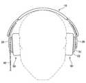
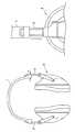
以下では、図1および図2を参照しながら、本発明の一実施形態に係るヘッドホンの構成について説明する。図1は、本実施形態に係るヘッドホンの装着状態を示す正面図である。図2は、ヘッドホンのアジャスト機構を示す縦断面図および側面図である。[Configuration of headphones]
Hereinafter, the configuration of a headphone according to an embodiment of the present invention will be described with reference to FIGS. 1 and 2. FIG. 1 is a front view showing a wearing state of the headphones according to the present embodiment. FIG. 2 is a longitudinal sectional view and a side view showing an adjustment mechanism of the headphones.
図1に示すように、ヘッドホンは、ヘッドバンド10、ヘッドバンド10の両端部に取り付けられたスライダ20、スライダ20の一端部に取り付けられたヘッドホンユニット50を含んで構成され、ヘッドバンド10およびスライダ20は、後述するアジャスト機構を介して接続される。 As shown in FIG. 1, the headphones include a
ヘッドバンド10は、装着者の頭頂部に沿って配置されるように、所定の曲率を有する略逆U字状または略C字状に形成される。スライダ20は、装着者の側頭部に沿って配置されるように、所定の曲率を有する円弧状または楕円円弧状に形成される。ヘッドバンド10およびスライダ20は、所定の可撓性を有するように、合成樹脂材、金属材などからなる帯状体として形成され、ヘッドバンド10およびスライダ20(後述するスライダカバー75を含むスライダアセンブリとして)は、略同一の断面形状を有する。 The
ヘッドバンド10およびスライダ20では、所定の範囲内で曲率半径を小さくする方向に付勢力が作用しており、曲率半径を大きくする方向に側圧が作用すると、付勢力に抗して所定の範囲内で曲率が変化する。 In the
ヘッドホンユニット50は、図示しないヘッドホンドライバを内蔵するハウジング51を有し、ハウジング51の放音面側には、例えばスポンジ材からなり、装着者の耳介を覆うように形成されたイヤーパッド52が設けられる。なお、ヘッドホンユニット50は、装着者の耳介を覆うように形成される代わりに、耳介上に配置されるように形成されてもよい。また、装着者の右側の耳介に装着されるヘッドホンユニット50には、ヘッドホンコード90が接続されている。 The
アジャスト機構は、装着者の頭部のサイズに適応するようにヘッドホンのサイズを調節する機構である。なお、本実施形態に係るヘッドホンでは、ヘッドバンド10の両端部にアジャスト機構が設けられるが、両端部のアジャスト機構が共通の構造を有するので、以下では、ヘッドバンド10の左端部に設けられたアジャスト機構について説明する。 The adjusting mechanism is a mechanism that adjusts the size of the headphones so as to adapt to the size of the head of the wearer. In the headphone according to the present embodiment, the adjustment mechanism is provided at both ends of the
図2に示すように、アジャスト機構において、ヘッドバンド10の端部には、長手方向に沿って所定の長さを有するように、スライダ20の周動範囲を規制するスライド溝30が設けられ、スライダ20の端部(ヘッドホンユニット50が取り付けられない側の端部)には、ヘッドバンド10に対してスライダ20を周動可能に保持するスライダガイド40が設けられる。スライダガイド40は、スライド溝30よりも短く、スライド溝30と略等幅であり、ヘッドバンド10およびスライダ20よりも高い剛性を有するように、合成樹脂材、金属材などから形成される。 As shown in FIG. 2, in the adjustment mechanism, a
スライダガイド40は、ヘッドバンド10の一面に対してヘッドバンド10の一面に対向するスライダ20の一面が周動可能なように、ヘッドバンド10の端部にスライダ20の一端部を保持する。なお、本実施形態に係るヘッドホンでは、ヘッドバンド10の内周面に対してスライダ20の外周面が周動可能に保持される。スライダガイド40は、スライド溝30に係合された状態でヘッドバンド10の端部にスライダ20を保持する。スライダガイド40は、スライド溝30に係合された状態でスライド溝30に沿って移動し、これにより、スライダ20は、スライダガイド40によりヘッドバンド10の端部に保持された状態でヘッドバンド10に対して周動する。 The
[ヘッドホンの詳細構造]
以下では、図3および図4を参照しながら、本実施形態に係るヘッドホンの詳細構造について説明する。図3は、ヘッドホンの詳細構造を示す分解斜視図である。図4は、ヘッドホンのアジャスト機構を示す横断面図である。[Detailed structure of headphones]
Hereinafter, the detailed structure of the headphones according to the present embodiment will be described with reference to FIGS. 3 and 4. FIG. 3 is an exploded perspective view showing the detailed structure of the headphones. FIG. 4 is a cross-sectional view showing the headphone adjustment mechanism.
図3に示すように、ヘッドホンは、ヘッドバンド10、スライダ20、スライダガイド40、およびヘッドホンユニット50の他に、ヘッドバンドカバー60、クッションカバー65、クッション70、スライダカバー75、スライダシート80、スペーサ85を含んで構成される。 As shown in FIG. 3, in addition to the
ヘッドバンド10は、所定の曲率を有する略逆U字状の帯状体として形成される。ヘッドバンド10は、非限定的に、例えばポリプロピレン(PP)、ボリプロピレン(BPP)などの合成樹脂材からなる。ヘッドバンド10の両端部には、スライダ20の周動範囲に対応するように周動領域11が設けられ、ヘッドバンド10の中央部には、ヘッドバンド10の両端部の周動領域11を接続する接続領域12が設けられる。周動領域11には、ヘッドバンド10の長手方向に沿って所定の長さを有するスライド溝30が設けられる。 The
スライド溝30は、図4に示すように、ヘッドバンド10を貫通する貫通溝部31(図4では、スライダガイド40の貫通部45が貫通している。)、および貫通溝部31の両側に設けられたフランジ溝部32を有する。フランジ溝部32は、周動領域11の外周面に貫通溝部31の両側に沿って設けられた凹部として形成され、貫通溝部31とともに階段状の横断面構造を有するスライド溝30を形成する。フランジ溝部32の両側には、スライダ20の周動範囲に対応して凹凸面33(波状面)が連続形成される(図5参照)。なお、凹凸面33は、フランジ溝部32の両側に形成される代わりに、フランジ溝部32の片側にのみ形成されてもよい。 As shown in FIG. 4, the
スライダ20は、所定の曲率を有する円弧状または楕円円弧状の帯状体として形成され、ヘッドバンド10と(スライダアセンブリとの間で)略同一の断面形状(ただし、スライド溝30の部分を除く)を有する。スライダ20は、非限定的に、例えばABSなどの合成樹脂材からなる。スライダ20の上端部には、スライダガイド40を雄ネジ44によりネジ固定するための雌ネジ21、およびスライダカバー75をネジ固定するための雌ネジ22が設けられる。スライダ20の下端部には、ヘッドホンユニット50を取り付けるための取付孔23、およびスライダカバー75をネジ固定するための雌ネジ24が設けられる。 The
ヘッドホンユニット50は、図示しないヘッドホンドライバを内蔵するハウジング51、および装着者の耳介に装着されるイヤーパッド52を有する。ヘッドホンユニット50は、取付プラグ53によりスライダ20およびスライダカバー75の取付孔23、77を介してスライダ20に取り付けられる。 The
スライダガイド40は、ヘッドバンド10およびスライダ20よりも高い剛性を有し、ヘッドバンド10の端部にスライダ20を保持する保持部材として形成される。スライダガイド40は、非限定的に、例えばポリアセダールなどの合成樹脂材からなる。スライダガイド40は、スライド溝30よりも短く、スライダ20溝と略等幅を有する、略矩形の部材として形成され、図4に示すように、貫通部45およびフランジ部46からなる横断面構造を有する。 The
貫通部45には、スライダガイド40をスライダ20の外周面に雄ネジ44によりネジ固定するための雌ネジ41(図4では、雄ネジ44が貫通している。)が設けられる。貫通部45は、底面がスライダ20の外周面に固定され、側面が貫通溝部31の側面に当接した状態で、貫通溝部31を貫通するように設けられる。フランジ部46は、底面がフランジ溝部32の底面に当接するように設けられる。 The through
スライダガイド40には、フランジ部46の両側に弾性片42が設けられ、弾性片42には、フランジ部46の両側方向に付勢力が作用している。弾性片42は、例えば、フランジ部46の側面からフランジ部46の長さ方向に沿ってL字状の切れ込みを入れることで形成される。弾性片42の先端には、弾性片42の付勢力により、フランジ溝部32に設けられた凹凸面33に係合する係合凸部43が設けられる。なお、弾性片42は、フランジ部46に形成された切れ込みにより形成される代わりに、例えば、フランジ部46に設けられたバネ機構により形成されてもよい。また、弾性片42の先端には、係合凸部43の代わりに、係合凹部が設けられてもよい。 The
ヘッドバンドカバー60は、ヘッドバンド10の周動領域11に対応する円弧状または楕円円弧状の被覆部材として形成される。ヘッドバンドカバー60には、長手方向の両側面が内周側に折り曲げられることで、ヘッドバンド10の周動領域11を挿通するための空間が形成される。ヘッドバンドカバー60は、ヘッドバンド10の周動領域11が挿通空間に挿通されることで、ヘッドバンド10の周動領域11を覆い隠す。ヘッドバンドカバー60は、ヘッドバンド10にスライド溝30などを設けることを容易にするために、一部品として構成されているが、例えば内倒し構造のヘッドバンド10を採用することで、ヘッドバンド10の一部として構成されてもよい。 The
クッションカバー65は、ヘッドバンド10の接続領域12に対応する筒状の被覆材として形成される。クッションカバー65は、帯状の衝撃緩衝材として形成されるクッション70、およびヘッドバンド10の接続領域12を覆うように、ヘッドバンド10に取り付けられる。 The
スライダカバー75は、スライダ20に対応する帯状の被覆部材として形成される。スライダカバー75の上端部には、スライダカバー75およびスライダシート80をスライダ20にネジ固定するための雌ネジ76が設けられ、スライダカバー75の下端部には、スライダ20およびスライダカバー75に対してヘッドホンユニット50を取り付けるための取付孔77、およびスライダカバー75をスライダ20にネジ固定するための雌ネジ78が設けられる。スライダカバー75の外周側には、スライダシート80を収納するための収納空間79が設けられている。 The
スペーサ85は、ヘッドバンド10の内周面とスライダ20の外周面との間に所定の隙間を確保するための楔状部材として形成される。なお、スペーサ85は、一部品として構成される代わりに、スライダガイド40またはスライダ20の一部として構成されてもよい。 The
ヘッドホンは、次の手順で組立てられる。まず、スライダシート80を収納した状態でスライダ20およびスライダカバー75をネジ結合することでスライダアセンブリが組立てられ、取付プラグ53により取付孔23、77を介してスライダアセンブリにヘッドホンユニット50が取り付けられる。また、ヘッドバンド10の接続領域12の内周面にクッション70を配置した状態で、接続領域12およびクッション70がクッションカバー65に挿通される。 The headphones are assembled in the following procedure. First, the slider assembly is assembled by screwing the
次に、ヘッドバンド10の内周面に対して、スペーサ85を介在させてスライダアセンブリの外周面を重ね合わせ、スライド溝30にスライダガイド40を係合させた状態で、スライダガイド40およびスライダアセンブリがネジ結合される。なお、スライダガイド40およびスライダアセンブリは、ネジ結合の代わりに、接着手段、締結手段などにより結合されてもよい。ここで、スライダガイド40は、貫通部45の底面がスライダ20の外周面に固定され、貫通部45の側面が貫通溝部31の側面に当接し、フランジ部46の底面がフランジ溝部32の底面(溝面)に当接するように、スライド溝30に係合される。また、スライダガイド40は、弾性片42の係合凸部43がフランジ溝部32の凹凸面33に係合するように、スライド溝30に係合される。そして、ヘッドバンド10に対してスライダアセンブリが組立てられた状態で、ヘッドバンド10の周動領域11がヘッドバンドカバー60に挿通される。 Next, the
[ヘッドホンの動作]
以下では、図5を参照しながら、ヘッドホンの動作について説明する。図5Aは、周動前の状態のヘッドホンを示す縦断面図および側面図であり、図5Bは、周動後の状態のヘッドホンを示す縦断面図および側面図である。なお、図5Aおよび図5Bには、ヘッドホンの左側部分のみが示されている。[Headphone operation]
Hereinafter, the operation of the headphones will be described with reference to FIG. FIG. 5A is a longitudinal sectional view and a side view showing the headphones in a state before the circumferential movement, and FIG. 5B is a longitudinal sectional view and a side view showing the headphones in a state after the circumferential movement. 5A and 5B show only the left side portion of the headphones.
図5Aに示すように、周動前の状態では、ヘッドホンのサイズが最小となるように調節されている。スライダガイド40は、スライド溝30の上端部に係合され、弾性片42の係合凸部43がフランジ溝部32の上端部で凹凸面33に係合している。スライダ20は、フランジ部46の底面がフランジ溝部32の底面に当接することで、ヘッドバンド10からの抜け落ちが防止されるとともに、弾性片42の係合凸部43がフランジ溝部32の凹凸面33に係合することで、ヘッドホンのサイズが調節された状態でヘッドバンド10に対して保持される。 As shown in FIG. 5A, the size of the headphones is adjusted to be minimum in the state before the rotation. The
この状態では、スライダガイド40がスライド溝30の上端部に当接することで、ヘッドホンのサイズを小さくする方向へのスライダ20の周動が規制される。なお、ヘッドホンのサイズが最大に調節されている状態でも同様に、スライダガイド40がスライド溝30の下端部に当接することで、ヘッドホンのサイズを大きくする方向へのスライダ20の周動が規制される。 In this state, the
図5Bに示すように、周動後の状態では、周動前の状態に比してヘッドホンのサイズが大きくなるように調節されている。スライダガイド40は、スライド溝30の中間部に係合され、弾性片42の係合凸部43がフランジ溝部32の中間部で凹凸面33に係合している。 As shown in FIG. 5B, the headphone is adjusted to have a larger size in the state after the peripheral movement than in the state before the peripheral movement. The
スライダ20を周動させると、スライド溝30に対してスライダガイド40が移動し、ヘッドホンのサイズが調節される。スライダガイド40は、貫通部45の側面が貫通溝部31の側面に当接し、フランジ部46の底面がフランジ溝部32の底面に当接することで、スライド溝30に移動をガイドされた状態でスライド溝30に対して移動する。 When the
また、スライダガイド40は、弾性片42の付勢力により、弾性片42の係合凸部43がフランジ溝部32の凹凸面33との間で係合・離脱を繰り返しながらスライド溝30に沿って移動する。これにより、係合凸部43と凹凸面33との間で係合抵抗(例えば、凹凸面33の凹部に係合凸部43が係合することで)を生じさせ、係合抵抗によりスライダガイド40の移動が規制されることで、凹凸面33の形状に応じてヘッドホンのサイズを段階的に調節可能なアジャスト機構を実現することができる。 Further, the
なお、段階調節可能なアジャスト機構を設ける代わりに、無段階調節可能なアジャスト機構を設けてもよい。この場合、例えば、フランジ溝部32の凹凸面33および弾性片42の係合凸部43を省略し、弾性片42の付勢力により弾性片42の側面とフランジ溝部32の側面との間で摩擦抵抗を生じさせ、摩擦抵抗によりスライダガイド40の移動を規制することで、無段階調節可能なアジャスト機構を実現することができる。なお、弾性片42は、フランジ部46に形成された切れ込みにより形成される代わりに、例えば、スライダガイド40に設けられたバネ機構、またはスライダガイド40とスライド溝30との間に設けられたストッパー機構により形成されてもよい。 Instead of providing an adjustment mechanism that can be adjusted stepwise, an adjustment mechanism that can be adjusted steplessly may be provided. In this case, for example, the concave and
ここで、ヘッドホンでは、スライド溝30に係合されたスライダガイド40により、ヘッドバンド10の内周面に対してヘッドバンド10の内周面に対向するスライダ20の外周面が周動可能なように、ヘッドバンド10の端部にスライダ20の一端部が保持されるので、ヘッドバンド10とスライダ20(スライダアセンブリ)との間で断面形状の差異を生じ難くすることができる。よって、ヘッドバンド10およびスライダ20(スライダアセンブリ)を略同一の断面形状とすることで、剛性の差異が生じ難くなるので、ヘッドバンド10およびスライダ20の全体で撓みを均一に生じさせることができる。これにより、装着者は、頭部のサイズに追従するように均一に撓んだ状態でヘッドホンを利用可能であり、ヘッドホンの装着性の低下を抑制することができる。 Here, in the headphone, the
なお、ヘッドバンド10およびスライダ20(スライダアセンブリ)を略同一の断面形状とせずに、材質の変更などにより剛性の差異を調整することも可能であるが、断面形状の小さな部材が相対的に脆くなり、部材の破損が生じ易くなるという別の問題を生じさせてしまう。参考として、断面形状の差異は、矩形部材の場合、部材厚の3乗および部材幅に比例する剛性の差異をもたらす。 Although the
また、ヘッドバンド10の内周面およびスライダ20の外周面を介して、ヘッドバンド10およびスライダ20よりも高い剛性を有するスライダガイド40により、ヘッドバンド10の端部にスライダ20の一端部を保持するので、スライダ20を挿入または挿通する内空断面の確保が不要となり、スライダガイド40により特に接続部での剛性の確保も容易となる。これにより、ヘッドバンド10の部材厚が抑制可能となり、ヘッドホンの薄型化を容易にすることができる。 Also, one end of the
さらに、例えば図8および図9で示すような、従来のヘッドバンド10では、ヘッドバンド10と断面形状の異なるスライダ20が周動時に露出すると、ヘッドバンド10とスライダ20とのデザイン上の連続性(一体性)が損なわれ、ヘッドホンの美観性が低下するという問題がある。一方、本実施形態に係るヘッドバンド10では、ヘッドバンド10およびスライダ20(スライダアセンブリ)を略同一の断面形状とすることで、スライダ20が周動時に露出しても、ヘッドバンド10とスライダ20とのデザイン上の連続性が損なわれず、ヘッドホンの美観性の低下を抑制することができる。 Further, in the
また、例えば図8および図9で示すような、従来のヘッドバンド10では、断面形状の差異に起因して大きな剛性の差異が生じると、ヘッドバンド10に比してスライダ20の撓みが大きくなり、ヘッドバンド10に対して両端のスライダ20が「ハ」の字状に撓んでしまい、ヘッドホンの美観性が低下するという問題がある。一方、本実施形態に係るヘッドバンド10では、ヘッドバンド10およびスライダ20(スライダアセンブリ)を略同一の断面形状とすることで、剛性の差異が生じ難くなり、ヘッドバンド10およびスライダ20の全体で撓みを均一に生じさせることができるので、ヘッドホンの美観性の低下を抑制することができる。 Further, in the
[傷防止機構]
ところで、アジャスト機構を有するヘッドホンでは、ヘッドバンド10に対してスライダ20を周動させるので、必然的にヘッドバンド10およびスライダ20に傷が生じ易くなる。特に、スライダ20に側圧が作用している状態でスライダ20を周動させると、ヘッドバンド10とスライダ20との接触面に大きな摩擦抵抗が生じることで、傷が生じ易くなる。これにより、ヘッドホンの美観性を低下させてしまう場合がある。[Scratch prevention mechanism]
By the way, in the headphone having the adjusting mechanism, the
このため、本実施形態に係るヘッドホンでは、ヘッドバンド10、スライダ20、およびスライダガイド40からなるアジャスト機構に特有の構成を利用することで、スライダ20の曲率半径Rsおよび曲率中心Osを調整するなど、図6に示すような傷防止機構が設けられる。図6は、ヘッドバンド10とスライダ20との取り付け状態を示す正面図である。なお、従来のアジャスト機構の構成では、ヘッドバンド1およびスライダ2が互いに挿入または挿通された状態で取り付けられるので、スライダ2の曲率半径Rsおよび曲率中心Osを調整すると、スライダ2の周動性を適切に確保することができなくなる。 For this reason, in the headphones according to the present embodiment, the radius of curvature Rs and the center of curvature Os of the
ヘッドホンは、スライダ20の曲率半径Rsがヘッドバンド10の曲率半径Rbよりも小さくなるように構成される。また、ヘッドホンは、スペーサ85(図3参照)により確保される隙間によって、スライダ20の曲率中心Osがヘッドバンド10の曲率中心Obよりも上方(ヘッドバンドの接続領域12に近接する方向)に位置するように構成される。また、ヘッドバンド10の内周面の先端部には、傷防止シート13が突設される。 The headphones are configured such that the curvature radius Rs of the
以上のようにスライダ20の曲率半径Rsおよび曲率中心Osを調整することで、ヘッドバンド10の先端側ほど、ヘッドバンド10とスライダ20との間に大きな隙間が確保される。よって、ヘッドバンド10に対してスライダ20を周動させた場合(特に側圧作用時など)でも、ヘッドバンド10およびスライダ20の摺動摩擦によりヘッドバンド10およびスライドに傷が生じ難くなり、ヘッドホンの美観性の低下を抑制することができる。また、スライダ20に過大な側圧が作用している状態でスライダ20を周動させた場合でも、傷防止シート13によりヘッドバンド10とスライダ20との間に隙間が維持されるので、傷の発生を防止することができる。 By adjusting the curvature radius Rs and the curvature center Os of the
[挟み込み防止機構]
また、アジャスト機構を有するヘッドホンでは、ヘッドバンド10に対してスライダ20を周動させることで、ヘッドバンド10とスライダ20との間に装着者の頭髪が挟み込まれ易くなり、ヘッドホンの装着性を低下させてしまう場合がある。このため、本実施形態に係るヘッドホンは、頭髪の挟み込みを防止するための挟み込み防止機構(挟み込み防止シート)が設けられる。[Pinch prevention mechanism]
Further, in the headphones having an adjustment mechanism, the
挟み込み防止シートは、図3に示すように、例えば、スライダ20の外周面の上端部(シート25)およびヘッドバンドカバー60の側面部(シート61)に設けられる。挟み込み防止シート25、61は、ヘッドバンド10の内周面とスライダ20の外周面との隙間を覆うように、スライダ20の外周面の上端部および側面部に設けられることで、隙間から異物が進入することを防止する。これにより、頭髪の挟み込みが生じ難くなり、ヘッドホンの装着性の低下を抑制することができる。 As shown in FIG. 3, the pinching prevention sheet is provided on, for example, the upper end portion (sheet 25) of the outer peripheral surface of the
[コード収納機構]
また、左右のヘッドホンユニット50から音声出力コード90が引出されているヘッドホンでは、装着者の身体にコード90が触れるなど、音声出力コード90の存在が煩雑に感じられ、ヘッドホンの装着性を低下させてしまう場合がある。このため、本実施形態に係るヘッドホンは、一方のヘッドホンユニット50(本実施形態の場合、右側のヘッドホンユニット50)から音声出力コード90を引出すために、左右のヘッドホンユニット50を接続する渡りコード91をヘッドバンド10およびスライダ20に収納するように構成される。[Cord storage mechanism]
In addition, in the headphones in which the
渡りコード91は、ヘッドバンド10およびスライダ20を介して左右のヘッドホンユニット50に内蔵されたヘッドホンドライバを接続するように配線される。渡りコード91の延長は、スライダ20の周動によりヘッドホンのサイズが最大に調節された状態に対応して決定されるので、ヘッドホンのサイズが最大に調節された状態にない場合には、たるんだ状態となる。このため、ヘッドバンド10の外周面には、図7に示すように、たるんだ状態の渡りコード91を収納可能とする収納空間26が設けられる。図7は、渡りコード91の収納機構を示す側面図および横断面図(断面A)である。 The
渡りコード91は、一方のヘッドホンドライバからスライダアセンブリの内部に挿通され、スライダアセンブリの上端部からスライド溝30を通じて収納空間26に引出され、ヘッドバンド10とヘッドバンドカバー60との間に挿通され、他方のスライダアセンブリを通じて他方のヘッドホンドライバに接続される。これにより、一方のヘッドホンユニット50から音声出力コード90を引出すことが容易となり、音声出力コード90の存在が煩雑に感じられなくなり、ヘッドホンの装着性の低下を抑制することができる。 The
以上、添付図面を参照しながら本発明の好適な実施形態について説明したが、本発明は係る例に限定されない。当業者であれば、特許請求の範囲に記載された技術的思想の範疇内において、各種の変更例または修正例に想到し得ることは明らかであり、それらについても当然に本発明の技術的範囲に属するものと了解される。 As mentioned above, although preferred embodiment of this invention was described referring an accompanying drawing, this invention is not limited to the example which concerns. It is obvious for those skilled in the art that various changes or modifications can be conceived within the scope of the technical idea described in the claims. It is understood that it belongs to.
なお、本実施形態に係るヘッドホンは、ヘッドバンド10の内周面に対してスライダ20の外周面が周動可能なように構成されているが、ヘッドバンドの外周面に対してスライダの内周面が周動可能なように構成されてもよい。また、本実施形態に係るヘッドホンでは、ヘッドバンド10にスライド溝30を設け、スライド溝30を介してスライダガイド40をスライダ20に固定しているが、スライダにスライド溝を設け、スライド溝を介してスライダガイドをヘッドバンドに固定してもよい。 The headphone according to the present embodiment is configured such that the outer peripheral surface of the
10 ヘッドバンド
20 スライダ
30 スライド溝
40 スライダガイド
50 ヘッドホンユニット10
Claims (5)
Translated fromJapanese可撓性を有し、一端部に前記ヘッドバンドが取り付けられ、他端部にヘッドホンユニットが取り付けられるスライダと、
前記ヘッドバンドの端部または前記スライダの一端部に設けられ、前記ヘッドバンドに対する前記スライダの周動を案内するスライド溝と、
前記ヘッドバンドおよび前記スライダよりも高い剛性を有し、前記スライド溝に係合された状態で、前記ヘッドバンドの一面に対して前記ヘッドバンドの一面に対向する前記スライダの一面が周動可能なように、前記ヘッドバンドの端部に前記スライダの一端部を保持するスライダガイドと、
を備える、ヘッドホン。A flexible headband;
A slider having flexibility, wherein the headband is attached to one end and a headphone unit is attached to the other end;
A slide groove that is provided at an end of the headband or at one end of the slider and guides the circumferential movement of the slider with respect to the headband;
One surface of the slider facing one surface of the headband is capable of rotating with respect to one surface of the headband, having higher rigidity than the headband and the slider, and being engaged with the slide groove. A slider guide for holding one end of the slider at the end of the headband,
Headphones equipped with.
前記スライダガイドには、付勢力により係合面に対して係合可能な係合部が設けられ、
前記スライダガイドは、前記スライダの周動に応じて前記スライド溝に対して相対的に移動し、前記係合部が前記被係合面に係合した状態で、前記スライド溝との係合抵抗により前記スライダの周動を規制する、請求項1に記載のヘッドホン。In the slide groove, an engaged surface corresponding to the circumferential movement range of the slider is formed,
The slider guide is provided with an engaging portion that can be engaged with the engaging surface by an urging force,
The slider guide moves relative to the slide groove in accordance with the circumferential movement of the slider, and the engagement resistance with the slide groove in a state where the engagement portion is engaged with the engaged surface. The headphone according to claim 1, wherein the circumferential movement of the slider is regulated by the above.
Priority Applications (5)
| Application Number | Priority Date | Filing Date | Title |
|---|---|---|---|
| JP2008212151AJP4737251B2 (en) | 2008-08-20 | 2008-08-20 | headphone |
| CN201310309184.5ACN103491474B (en) | 2008-08-20 | 2009-07-30 | Headphone |
| CN2009101655739ACN101656903B (en) | 2008-08-20 | 2009-07-30 | headphones |
| US12/543,687US8565468B2 (en) | 2008-08-20 | 2009-08-19 | Headphone |
| US14/031,703US9167335B2 (en) | 2008-08-20 | 2013-09-19 | Headphone |
Applications Claiming Priority (1)
| Application Number | Priority Date | Filing Date | Title |
|---|---|---|---|
| JP2008212151AJP4737251B2 (en) | 2008-08-20 | 2008-08-20 | headphone |
Publications (2)
| Publication Number | Publication Date |
|---|---|
| JP2010050647Atrue JP2010050647A (en) | 2010-03-04 |
| JP4737251B2 JP4737251B2 (en) | 2011-07-27 |
Family
ID=41696431
Family Applications (1)
| Application Number | Title | Priority Date | Filing Date |
|---|---|---|---|
| JP2008212151AExpired - Fee RelatedJP4737251B2 (en) | 2008-08-20 | 2008-08-20 | headphone |
Country Status (3)
| Country | Link |
|---|---|
| US (2) | US8565468B2 (en) |
| JP (1) | JP4737251B2 (en) |
| CN (2) | CN101656903B (en) |
Cited By (6)
| Publication number | Priority date | Publication date | Assignee | Title |
|---|---|---|---|---|
| WO2016059832A1 (en)* | 2014-10-15 | 2016-04-21 | 株式会社オーディオテクニカ | Headphone |
| JP2017510199A (en)* | 2014-03-26 | 2017-04-06 | ボーズ・コーポレーションBose Corporation | head band |
| JP2018059246A (en)* | 2016-10-07 | 2018-04-12 | ミドリ安全株式会社 | helmet |
| EP3313087A1 (en) | 2016-10-18 | 2018-04-25 | Audio-Technica Corporation | Digitally driven headphone |
| JP2018088661A (en)* | 2016-11-30 | 2018-06-07 | オンキヨー株式会社 | headphone |
| JP2020014108A (en)* | 2018-07-18 | 2020-01-23 | 株式会社Jvcケンウッド | headphone |
Families Citing this family (58)
| Publication number | Priority date | Publication date | Assignee | Title |
|---|---|---|---|---|
| US6735784B2 (en)* | 2002-01-28 | 2004-05-18 | 180S, Inc. | Apparatus and method for making an ear warmer and an ear warmer frame |
| JP4946538B2 (en)* | 2007-03-13 | 2012-06-06 | ソニー株式会社 | Headphone device |
| JP4631939B2 (en) | 2008-06-27 | 2011-02-16 | ソニー株式会社 | Noise reducing voice reproducing apparatus and noise reducing voice reproducing method |
| JP4737251B2 (en) | 2008-08-20 | 2011-07-27 | ソニー株式会社 | headphone |
| JP4894849B2 (en)* | 2008-11-28 | 2012-03-14 | ソニー株式会社 | Earpiece and earphone |
| CN102232888B (en)* | 2010-04-21 | 2013-08-21 | 声腾企业有限公司 | Earmuff structure |
| US9529197B2 (en) | 2012-03-21 | 2016-12-27 | Google Inc. | Wearable device with input and output structures |
| CN102547516A (en)* | 2012-03-09 | 2012-07-04 | 王承延 | Connecting rod folding device for headset |
| US9277334B1 (en) | 2012-03-21 | 2016-03-01 | Google Inc. | Wearable computing device authentication using bone conduction |
| EP2680607A1 (en)* | 2012-06-29 | 2014-01-01 | GN Netcom A/S | A headset device with fitting memory |
| CN103686506B (en)* | 2012-09-17 | 2018-02-02 | 技嘉科技股份有限公司 | Headset device |
| US8861770B2 (en)* | 2013-01-23 | 2014-10-14 | Koss Corporation | Headband for personal speakers |
| US8737668B1 (en)* | 2013-01-23 | 2014-05-27 | Koss Corporation | Headband for personal speakers |
| US9749728B2 (en)* | 2013-06-07 | 2017-08-29 | Microsoft Technology Licensing, Llc | Audio headset accommodating ear geometry variations |
| CN105340293B (en)* | 2013-06-28 | 2019-04-09 | 索尼公司 | Headphone |
| US20150092976A1 (en)* | 2013-09-30 | 2015-04-02 | Harman International Industries, Incorporated | Earpad |
| USD727286S1 (en)* | 2013-10-14 | 2015-04-21 | Sennheiser Electronic Gmbh & Co. Kg | Headphones |
| USD741288S1 (en)* | 2013-10-14 | 2015-10-20 | Sennheiser Electronic Gmbh & Co. Kg | Headphones |
| USD727285S1 (en)* | 2013-10-14 | 2015-04-21 | Sennheiser Electronic Gmbh & Co. Kg | Headphones |
| DK2892246T3 (en) | 2014-01-07 | 2020-01-02 | Sennheiser Communications As | Headphones with passage over the head |
| US9609415B2 (en)* | 2014-03-26 | 2017-03-28 | Bose Corporation | Headphones with cable management |
| US9736571B2 (en)* | 2014-11-10 | 2017-08-15 | The Quest Group | Headphone suspension system |
| USD747291S1 (en)* | 2015-01-12 | 2016-01-12 | Monster Llc | Headphones |
| EP3254075B1 (en)* | 2015-02-03 | 2020-02-19 | 3M Innovative Properties Company | Improved comfort headband for hearing protectors |
| US9712909B2 (en) | 2015-07-15 | 2017-07-18 | Voyetra Trutle Beach, Inc. | Headset with force isolation |
| RU2606928C1 (en)* | 2015-10-02 | 2017-01-10 | Валентин Валерьевич Казанжи | Headphones headset |
| US10178463B2 (en)* | 2016-03-07 | 2019-01-08 | Apple Inc. | Headphones |
| US9883288B2 (en)* | 2016-03-08 | 2018-01-30 | Bose Corporation | Compliant constrained headband spring |
| US9854348B2 (en)* | 2016-04-04 | 2017-12-26 | Nikola Taisha Naylor-Warren | Flexible conformal cushioned headphones |
| USD793359S1 (en)* | 2016-05-08 | 2017-08-01 | Chris J. Katopis | Portion of an adjustable headset for an electronic device |
| US10231055B2 (en)* | 2016-05-31 | 2019-03-12 | Sennheiser Communications A/S | Gaming headset with adjustable contact pressure |
| CN106331931B (en)* | 2016-10-20 | 2020-03-31 | 深圳市冠旭电子股份有限公司 | Head band earphone |
| KR20180116759A (en)* | 2017-04-17 | 2018-10-25 | 헤드셋, 엘엘씨 | Headset accessory |
| USD843349S1 (en)* | 2017-06-05 | 2019-03-19 | Logitech Europe S.A. | Headphone |
| USD848395S1 (en)* | 2017-08-07 | 2019-05-14 | Plantronics, Inc. | Communications headset |
| USD870066S1 (en)* | 2017-11-27 | 2019-12-17 | Urbanista AB | Headphones |
| US20190215593A1 (en)* | 2018-01-11 | 2019-07-11 | Te-Sheng LIU | Highly-Closed Headphone Apparatus with Wearing Comfort |
| JP1617794S (en)* | 2018-01-22 | 2018-11-12 | ||
| CN108563022A (en)* | 2018-03-28 | 2018-09-21 | 深圳创维新世界科技有限公司 | It wears and wear-type electronic equipment |
| CN108433263A (en)* | 2018-05-17 | 2018-08-24 | 广东小天才科技有限公司 | Watchband and watch |
| US10616673B2 (en)* | 2018-05-17 | 2020-04-07 | Bose Corporation | Snapfold headband cushion |
| JP7087757B2 (en)* | 2018-07-18 | 2022-06-21 | 株式会社Jvcケンウッド | headphone |
| USD877115S1 (en)* | 2018-09-13 | 2020-03-03 | Plantronics, Inc. | Communications headset |
| CN109413533B (en)* | 2018-12-07 | 2023-12-22 | 歌尔科技有限公司 | Headset |
| EP3675521A1 (en)* | 2018-12-27 | 2020-07-01 | GN Audio A/S | A headphone with a headband guiding mechanism |
| EP3675514B1 (en)* | 2018-12-27 | 2022-08-03 | GN Audio A/S | A headphone with a headband friction mechanism |
| US11672990B2 (en) | 2019-01-15 | 2023-06-13 | Stimwave Technologies Incorporated | Headsets for positioning electronic devices |
| USD899401S1 (en)* | 2019-05-15 | 2020-10-20 | Apple Inc. | Headphones |
| USD935433S1 (en)* | 2019-11-01 | 2021-11-09 | Harman International Industries, Incorporated | Headphone |
| USD881843S1 (en)* | 2019-12-23 | 2020-04-21 | Shenzhen Qianhai Patuoxun Network And Technology Co., Ltd | Headphones |
| CN113225648A (en)* | 2021-04-29 | 2021-08-06 | 东莞市魅音科技有限公司 | Earphone with stereo sound effect scene |
| USD950521S1 (en)* | 2021-05-11 | 2022-05-03 | Shenzhen Jing Peng Xing Electronic Technology Co., Ltd. | Headphone |
| JP1723544S (en)* | 2021-11-23 | 2022-08-30 | headphone | |
| CN114640919B (en)* | 2022-03-23 | 2025-08-01 | 深圳市豪恩声学股份有限公司 | Headband mechanism and headphone |
| USD1016780S1 (en)* | 2022-05-11 | 2024-03-05 | Anker Innovations Technology Co., Ltd. | Earphone |
| CN217985344U (en)* | 2022-05-25 | 2022-12-06 | 东莞北欧智能科技有限公司 | Headset capable of randomly replacing multiple parts without professional tools |
| US20240031715A1 (en)* | 2022-07-21 | 2024-01-25 | Dell Products L.P. | Information handling system headset with adjustable headband tensioner |
| USD1055889S1 (en)* | 2022-09-15 | 2024-12-31 | Anker Innovations Technology Co., Ltd. | Headphone |
Citations (6)
| Publication number | Priority date | Publication date | Assignee | Title |
|---|---|---|---|---|
| JPS4823736Y1 (en)* | 1969-07-31 | 1973-07-10 | ||
| JPS56167688A (en)* | 1980-05-30 | 1981-12-23 | Toagosei Chem Ind Co Ltd | Urethane bicycloorthoester |
| JPS5882089A (en)* | 1981-11-11 | 1983-05-17 | Matsushita Electric Ind Co Ltd | Compressor |
| JPS60108093A (en)* | 1983-11-17 | 1985-06-13 | 三洋電機株式会社 | Recirculation type dryer |
| JPS60178798A (en)* | 1984-02-03 | 1985-09-12 | Matsushita Electric Ind Co Ltd | headphone |
| JPS6142186A (en)* | 1984-08-01 | 1986-02-28 | Matsushita Electric Ind Co Ltd | Manufacturing method of semiconductor laser device |
Family Cites Families (30)
| Publication number | Priority date | Publication date | Assignee | Title |
|---|---|---|---|---|
| US3272926A (en)* | 1963-04-24 | 1966-09-13 | Dimensional Products Inc | Headphone assembly |
| US3748657A (en)* | 1967-01-17 | 1973-07-31 | Bentex Corp Carbondale | Safety helmet with retractable eye shield |
| JPS4823736U (en) | 1971-07-30 | 1973-03-19 | ||
| JPS616712Y2 (en) | 1980-05-16 | 1986-02-28 | ||
| JPS6029270Y2 (en) | 1980-05-20 | 1985-09-04 | パイオニア株式会社 | Headband adjustment mechanism |
| JPS5882089U (en) | 1981-11-26 | 1983-06-03 | 株式会社オ−デイオテクニカ | headphone |
| AT371657B (en)* | 1982-03-01 | 1983-07-25 | Goerike Rudolf | BRACKET FOR A COMBINABLE HEADPHONE |
| US4546215A (en)* | 1983-10-07 | 1985-10-08 | Ferraro Michael V | Detachable earmuffs for headsets |
| JPS60108093U (en) | 1983-12-23 | 1985-07-23 | 株式会社 オ−デイオテクニカ | headphone band stopper |
| GB2159366B (en)* | 1984-05-21 | 1987-12-09 | Northern Telecom Ltd | Communications headset |
| JPS6142186U (en) | 1984-08-23 | 1986-03-18 | オンキヨー株式会社 | headphone |
| US4727585A (en)* | 1986-11-24 | 1988-02-23 | Telex Communications, Inc. | Adjustable tension support band for headset |
| SE463803B (en)* | 1988-04-28 | 1991-01-28 | Milmas Ab | SPRING MOUNTING ARM FOR HEARING PROTECTION |
| US5033094A (en)* | 1990-06-25 | 1991-07-16 | Hung Huang Chiang | Adjustable headset |
| US5185807A (en)* | 1991-05-08 | 1993-02-09 | David Clark Company Incorporated | Headset with multi-position stirrup assemblies |
| JPH0654391A (en) | 1992-06-05 | 1994-02-25 | Sony Corp | Head phone |
| US5357585A (en)* | 1993-07-09 | 1994-10-18 | Khyber Technologies Corporation | Headphone assembly |
| JP3610618B2 (en) | 1995-03-17 | 2005-01-19 | ソニー株式会社 | headphone |
| JP3045051B2 (en)* | 1995-08-17 | 2000-05-22 | ソニー株式会社 | Headphone equipment |
| US6754361B1 (en)* | 1997-04-17 | 2004-06-22 | 3M Innovative Properties Company | Ergonomic headset assembly |
| US5793878A (en)* | 1997-06-05 | 1998-08-11 | Chang; Ching-Wen | Headset microphone having a location apparatus |
| DE29811119U1 (en)* | 1998-06-22 | 1998-09-10 | Fang, Kuo-Yun, Taipeh/T'ai-pei | Adjustment device for a helmet band |
| US7124425B1 (en)* | 1999-03-08 | 2006-10-17 | Immersion Entertainment, L.L.C. | Audio/video system and method utilizing a head mounted apparatus with noise attenuation |
| JP2001197581A (en)* | 2000-01-07 | 2001-07-19 | Sony Corp | Headphone system |
| SE0000465D0 (en)* | 2000-02-15 | 2000-02-15 | Kompositprodukter Ab | Ear protection |
| EP1130880A1 (en)* | 2000-02-29 | 2001-09-05 | Silicomp SPA | Headset and head support for headset. |
| US6724906B2 (en)* | 2002-05-07 | 2004-04-20 | Alex Naksen | Adjustable headphone |
| JP2007336432A (en) | 2006-06-19 | 2007-12-27 | Audio Technica Corp | headphone |
| JP4403429B2 (en)* | 2007-03-08 | 2010-01-27 | ソニー株式会社 | Signal processing apparatus, signal processing method, and program |
| JP4737251B2 (en) | 2008-08-20 | 2011-07-27 | ソニー株式会社 | headphone |
- 2008
- 2008-08-20JPJP2008212151Apatent/JP4737251B2/ennot_activeExpired - Fee Related
- 2009
- 2009-07-30CNCN2009101655739Apatent/CN101656903B/ennot_activeExpired - Fee Related
- 2009-07-30CNCN201310309184.5Apatent/CN103491474B/ennot_activeExpired - Fee Related
- 2009-08-19USUS12/543,687patent/US8565468B2/enactiveActive
- 2013
- 2013-09-19USUS14/031,703patent/US9167335B2/ennot_activeExpired - Fee Related
Patent Citations (6)
| Publication number | Priority date | Publication date | Assignee | Title |
|---|---|---|---|---|
| JPS4823736Y1 (en)* | 1969-07-31 | 1973-07-10 | ||
| JPS56167688A (en)* | 1980-05-30 | 1981-12-23 | Toagosei Chem Ind Co Ltd | Urethane bicycloorthoester |
| JPS5882089A (en)* | 1981-11-11 | 1983-05-17 | Matsushita Electric Ind Co Ltd | Compressor |
| JPS60108093A (en)* | 1983-11-17 | 1985-06-13 | 三洋電機株式会社 | Recirculation type dryer |
| JPS60178798A (en)* | 1984-02-03 | 1985-09-12 | Matsushita Electric Ind Co Ltd | headphone |
| JPS6142186A (en)* | 1984-08-01 | 1986-02-28 | Matsushita Electric Ind Co Ltd | Manufacturing method of semiconductor laser device |
Cited By (8)
| Publication number | Priority date | Publication date | Assignee | Title |
|---|---|---|---|---|
| JP2017510199A (en)* | 2014-03-26 | 2017-04-06 | ボーズ・コーポレーションBose Corporation | head band |
| WO2016059832A1 (en)* | 2014-10-15 | 2016-04-21 | 株式会社オーディオテクニカ | Headphone |
| JP2016082349A (en)* | 2014-10-15 | 2016-05-16 | 株式会社オーディオテクニカ | headphone |
| JP2018059246A (en)* | 2016-10-07 | 2018-04-12 | ミドリ安全株式会社 | helmet |
| EP3313087A1 (en) | 2016-10-18 | 2018-04-25 | Audio-Technica Corporation | Digitally driven headphone |
| US10117013B2 (en) | 2016-10-18 | 2018-10-30 | Audio-Technica Corporation | Digitally driven headphone |
| JP2018088661A (en)* | 2016-11-30 | 2018-06-07 | オンキヨー株式会社 | headphone |
| JP2020014108A (en)* | 2018-07-18 | 2020-01-23 | 株式会社Jvcケンウッド | headphone |
Also Published As
| Publication number | Publication date |
|---|---|
| US9167335B2 (en) | 2015-10-20 |
| CN101656903B (en) | 2013-08-28 |
| US20140023222A1 (en) | 2014-01-23 |
| US20100046782A1 (en) | 2010-02-25 |
| CN103491474B (en) | 2016-06-15 |
| US8565468B2 (en) | 2013-10-22 |
| JP4737251B2 (en) | 2011-07-27 |
| CN101656903A (en) | 2010-02-24 |
| CN103491474A (en) | 2014-01-01 |
Similar Documents
| Publication | Publication Date | Title |
|---|---|---|
| JP4737251B2 (en) | headphone | |
| EP2081404B1 (en) | Headphone | |
| US10178476B2 (en) | Compliant constrained headband spring | |
| US8411893B2 (en) | Headphone | |
| JP2022182745A (en) | headphone | |
| US8532324B2 (en) | Headphone | |
| US8573353B2 (en) | Long-wearing deep-insertion ear tip | |
| US20170034611A1 (en) | Near-ear speaker device | |
| JP6442719B2 (en) | headphone | |
| JP2010041632A (en) | Headphone | |
| US11297408B2 (en) | In-ear earpiece retaining structure | |
| JP2012054780A (en) | Ear pad | |
| JP2011082851A (en) | Headphone device | |
| JP2016015609A (en) | headphone | |
| JP2009060348A (en) | Headphone | |
| JP2010252132A (en) | Stereo earphone | |
| JP2000201390A (en) | Headphones | |
| CN222515348U (en) | Elastic protective sleeve, ear-clamping earphone and earphone assembly | |
| CN222916170U (en) | Telephone traffic earphone and integrated silica gel headband sliding structure thereof | |
| CN222706603U (en) | Earphone | |
| CN222706605U (en) | earphone | |
| US12439195B2 (en) | Headphone | |
| CN216795250U (en) | Headband sheath structure and headset | |
| JP5416017B2 (en) | Glasses modern | |
| CN115914916A (en) | Wear spring assembly and headphone |
Legal Events
| Date | Code | Title | Description |
|---|---|---|---|
| A977 | Report on retrieval | Free format text:JAPANESE INTERMEDIATE CODE: A971007 Effective date:20100531 | |
| A131 | Notification of reasons for refusal | Free format text:JAPANESE INTERMEDIATE CODE: A131 Effective date:20100622 | |
| A521 | Request for written amendment filed | Free format text:JAPANESE INTERMEDIATE CODE: A523 Effective date:20100810 | |
| TRDD | Decision of grant or rejection written | ||
| A01 | Written decision to grant a patent or to grant a registration (utility model) | Free format text:JAPANESE INTERMEDIATE CODE: A01 Effective date:20110405 | |
| A61 | First payment of annual fees (during grant procedure) | Free format text:JAPANESE INTERMEDIATE CODE: A61 Effective date:20110418 | |
| R151 | Written notification of patent or utility model registration | Ref document number:4737251 Country of ref document:JP Free format text:JAPANESE INTERMEDIATE CODE: R151 | |
| FPAY | Renewal fee payment (event date is renewal date of database) | Free format text:PAYMENT UNTIL: 20140513 Year of fee payment:3 | |
| R250 | Receipt of annual fees | Free format text:JAPANESE INTERMEDIATE CODE: R250 | |
| R250 | Receipt of annual fees | Free format text:JAPANESE INTERMEDIATE CODE: R250 | |
| R250 | Receipt of annual fees | Free format text:JAPANESE INTERMEDIATE CODE: R250 | |
| R250 | Receipt of annual fees | Free format text:JAPANESE INTERMEDIATE CODE: R250 | |
| R250 | Receipt of annual fees | Free format text:JAPANESE INTERMEDIATE CODE: R250 | |
| R250 | Receipt of annual fees | Free format text:JAPANESE INTERMEDIATE CODE: R250 | |
| R250 | Receipt of annual fees | Free format text:JAPANESE INTERMEDIATE CODE: R250 | |
| LAPS | Cancellation because of no payment of annual fees |