JP2010035984A - X-ray imaging apparatus - Google Patents
X-ray imaging apparatusDownload PDFInfo
- Publication number
- JP2010035984A JP2010035984AJP2008205689AJP2008205689AJP2010035984AJP 2010035984 AJP2010035984 AJP 2010035984AJP 2008205689 AJP2008205689 AJP 2008205689AJP 2008205689 AJP2008205689 AJP 2008205689AJP 2010035984 AJP2010035984 AJP 2010035984A
- Authority
- JP
- Japan
- Prior art keywords
- imaging
- ray
- subject
- unit
- image capturing
- Prior art date
- Legal status (The legal status is an assumption and is not a legal conclusion. Google has not performed a legal analysis and makes no representation as to the accuracy of the status listed.)
- Pending
Links
Images


Classifications
- A—HUMAN NECESSITIES
- A61—MEDICAL OR VETERINARY SCIENCE; HYGIENE
- A61B—DIAGNOSIS; SURGERY; IDENTIFICATION
- A61B6/00—Apparatus or devices for radiation diagnosis; Apparatus or devices for radiation diagnosis combined with radiation therapy equipment
- A61B6/02—Arrangements for diagnosis sequentially in different planes; Stereoscopic radiation diagnosis
- A61B6/03—Computed tomography [CT]
- A61B6/032—Transmission computed tomography [CT]
- A61B6/035—Mechanical aspects of CT
- A—HUMAN NECESSITIES
- A61—MEDICAL OR VETERINARY SCIENCE; HYGIENE
- A61B—DIAGNOSIS; SURGERY; IDENTIFICATION
- A61B6/00—Apparatus or devices for radiation diagnosis; Apparatus or devices for radiation diagnosis combined with radiation therapy equipment
- A61B6/02—Arrangements for diagnosis sequentially in different planes; Stereoscopic radiation diagnosis
- A61B6/03—Computed tomography [CT]
- A61B6/032—Transmission computed tomography [CT]
- A—HUMAN NECESSITIES
- A61—MEDICAL OR VETERINARY SCIENCE; HYGIENE
- A61B—DIAGNOSIS; SURGERY; IDENTIFICATION
- A61B6/00—Apparatus or devices for radiation diagnosis; Apparatus or devices for radiation diagnosis combined with radiation therapy equipment
- A61B6/04—Positioning of patients; Tiltable beds or the like
- A—HUMAN NECESSITIES
- A61—MEDICAL OR VETERINARY SCIENCE; HYGIENE
- A61B—DIAGNOSIS; SURGERY; IDENTIFICATION
- A61B6/00—Apparatus or devices for radiation diagnosis; Apparatus or devices for radiation diagnosis combined with radiation therapy equipment
- A61B6/44—Constructional features of apparatus for radiation diagnosis
- A61B6/4429—Constructional features of apparatus for radiation diagnosis related to the mounting of source units and detector units
- A61B6/4435—Constructional features of apparatus for radiation diagnosis related to the mounting of source units and detector units the source unit and the detector unit being coupled by a rigid structure
- A61B6/4441—Constructional features of apparatus for radiation diagnosis related to the mounting of source units and detector units the source unit and the detector unit being coupled by a rigid structure the rigid structure being a C-arm or U-arm
- A—HUMAN NECESSITIES
- A61—MEDICAL OR VETERINARY SCIENCE; HYGIENE
- A61B—DIAGNOSIS; SURGERY; IDENTIFICATION
- A61B6/00—Apparatus or devices for radiation diagnosis; Apparatus or devices for radiation diagnosis combined with radiation therapy equipment
- A61B6/58—Testing, adjusting or calibrating thereof
- A61B6/587—Alignment of source unit to detector unit
- A—HUMAN NECESSITIES
- A61—MEDICAL OR VETERINARY SCIENCE; HYGIENE
- A61B—DIAGNOSIS; SURGERY; IDENTIFICATION
- A61B6/00—Apparatus or devices for radiation diagnosis; Apparatus or devices for radiation diagnosis combined with radiation therapy equipment
- A61B6/44—Constructional features of apparatus for radiation diagnosis
- A61B6/4423—Constructional features of apparatus for radiation diagnosis related to hygiene or sterilisation
Landscapes
- Health & Medical Sciences (AREA)
- Life Sciences & Earth Sciences (AREA)
- Engineering & Computer Science (AREA)
- Medical Informatics (AREA)
- Radiology & Medical Imaging (AREA)
- Molecular Biology (AREA)
- Biophysics (AREA)
- Nuclear Medicine, Radiotherapy & Molecular Imaging (AREA)
- Optics & Photonics (AREA)
- Pathology (AREA)
- Physics & Mathematics (AREA)
- Biomedical Technology (AREA)
- Heart & Thoracic Surgery (AREA)
- High Energy & Nuclear Physics (AREA)
- Surgery (AREA)
- Animal Behavior & Ethology (AREA)
- General Health & Medical Sciences (AREA)
- Public Health (AREA)
- Veterinary Medicine (AREA)
- Pulmonology (AREA)
- Theoretical Computer Science (AREA)
- Apparatus For Radiation Diagnosis (AREA)
Abstract
Description
Translated fromJapanese本発明は、被写体を透過したX線によりX線像を得るX線撮影装置に関するものである。 The present invention relates to an X-ray imaging apparatus that obtains an X-ray image with X-rays transmitted through a subject.
一般に、X線撮影装置はX線発生部とX線検出器を内蔵する撮影部を対向して配置し、X線発生部と撮影部との間に撮影対象である人体等の被写体を配置することにより撮影を行っている。X線発生部及び被写体に対して撮影部の位置決めをした後に、X線を曝射することによりX線撮影を行い、必要な画像を取得している。 In general, in an X-ray imaging apparatus, an X-ray generation unit and an imaging unit including an X-ray detector are arranged to face each other, and a subject such as a human body that is an imaging target is arranged between the X-ray generation unit and the imaging unit. Shooting is done. After positioning the imaging unit with respect to the X-ray generation unit and the subject, X-ray imaging is performed by exposing X-rays, and necessary images are acquired.
近年、画像処理装置の高速化が著しく、二次元の静止画像の取得に加えて、動画像や三次元像を取得する装置も普及しつつある。この三次元像を取得するためには、従来は専用のコンピューテッドトモグラフィ装置(CT装置)を用いて撮影する方法が主流であった。しかし、最近ではイメージインテンシファイア(I.I.)、平面検出器(フラットパネルディテクタ)等の二次元センサを用い、二次元画像から演算により三次元像を取得するコーンビームCT撮影法(CBCT撮影)も実用化されている。このCBCT撮影は、撮影系と被写体との間に相対運動が生ずることを利用しており、多数の二次元のX線投影画像を取得し、得られたX線撮影画像を基に演算することによって断層画像や三次元像を生成している。 In recent years, the speed of image processing apparatuses has been remarkably increased, and apparatuses that acquire moving images and three-dimensional images in addition to acquisition of two-dimensional still images are becoming widespread. In order to acquire this three-dimensional image, conventionally, a method of photographing using a dedicated computed tomography apparatus (CT apparatus) has been mainstream. However, recently, a cone beam CT imaging method (CBCT) that uses a two-dimensional sensor such as an image intensifier (II) or a flat detector (flat panel detector) to obtain a three-dimensional image by calculation from a two-dimensional image. Photography) has also been put to practical use. This CBCT imaging utilizes the fact that relative motion occurs between the imaging system and the subject, and obtains a large number of two-dimensional X-ray projection images and performs calculations based on the obtained X-ray imaging images. A tomographic image or a three-dimensional image is generated.
Cアーム撮影装置を利用したCBCT撮影においては、X線発生部及び撮影部が、ベッド等の被写体支持部に支持された被写体の周囲を周回することにより、被写体についての多角的なX線投影画像を取得する。また、別のCBCT撮影として、特許文献1に示すように、ターンテーブル上に支持された被写体を回転させながらX線を曝射することにより、多角的に被写体のX線投影画像を取得している。更に、特許文献2のように、CBCT撮影と一般のX線静止画撮影を兼用可能な装置も提案されている。 In CBCT imaging using a C-arm imaging apparatus, an X-ray generation unit and an imaging unit circulate around a subject supported by a subject support unit such as a bed, so that a polygonal X-ray projection image of the subject is obtained. To get. Further, as another CBCT imaging, as shown in
しかし、一般にX線撮影においては、撮影部に被写体をできる限り接近させて撮影を行ったり、或いは撮影部の外装部分に被写体の胸や顎等を接触させて撮影を行う。何故なら、被写体と撮影部のX線検出器との距離が近いほど、散乱線によるぼけの影響が少ない鮮明な画像を取得できるためである。特に、胸部の静止画撮影をする場合においては、胸部から肩部までを撮影部の前面に密着させた状態で撮影することが好ましく、被写体の左右の腕を撮影部のそれぞれの側面から背面に沿って配置しておくことが好ましい。そのために、撮影部の側面から背面の位置に沿って、手摺りを配備している撮影装置も少なくない。 However, in general, in X-ray imaging, imaging is performed with the subject as close as possible to the imaging unit, or imaging is performed by bringing the chest, chin, etc. of the subject into contact with the exterior part of the imaging unit. This is because the closer the distance between the subject and the X-ray detector of the imaging unit, the clearer the image that is less affected by the scattered radiation. In particular, when taking a still image of the chest, it is preferable to take a picture from the chest to the shoulder in close contact with the front of the photographing unit, and the left and right arms of the subject are placed from the respective sides of the photographing unit to the back. It is preferable to arrange along. For this reason, there are not a few imaging devices provided with handrails along the position from the side to the back of the imaging unit.
また、X線管球から曝射されるX線は、不要な部分をX線絞りによってカットされ、撮影に有効な範囲のみに照射される。通常では、X線検出器の画像取得領域に、X線照射範囲が略一致するようにX線絞りを設けて、X線検出器の検出面を底面とし、X線管球を頂点とした錘状、多くは四角錘状の空間にX線を曝射することにより、この部分の投影画像を得る。 Further, the X-rays emitted from the X-ray tube are irradiated to only an effective range for imaging by cutting unnecessary portions with an X-ray diaphragm. Usually, an X-ray diaphragm is provided in the image acquisition region of the X-ray detector so that the X-ray irradiation ranges substantially coincide with each other, a weight having the detection surface of the X-ray detector as a bottom surface and an X-ray tube as a vertex A projected image of this part is obtained by exposing X-rays to a space, mostly a quadrangular pyramid.
X線は放射状に拡がって進むため、撮影部と被写体の距離が離れているほど、被写体のX線検出面での投影は実物よりも拡大された像となる。撮影部と被写体を接近させた一般のX線撮影においては、等倍に近い画像が得られ、X線検出器の限られた画像取得領域に被写体の必要な部位を全て納めるために有効である。 Since the X-rays spread radially and advance, the projection of the subject on the X-ray detection surface becomes an enlarged image as the distance between the imaging unit and the subject increases. In general X-ray imaging in which the imaging unit and the subject are brought close to each other, an image that is close to the same magnification is obtained, and it is effective to fit all necessary parts of the subject in the limited image acquisition area of the X-ray detector. .
一方、CBCT撮影の場合には上述の相対的な回転運動が必要であり、X線撮影装置と被写体との衝突の危険を低減するために、撮影部と被写体との距離を或る程度、離す必要がある。その結果、X線検出面における被写体の投影の拡大率はその分だけ大きくなり、被写体の必要な部位を全て納めるためには、X線検出器の検出面の領域を広くする必要がある。 On the other hand, in the case of CBCT imaging, the above-described relative rotational motion is necessary, and in order to reduce the risk of collision between the X-ray imaging apparatus and the subject, the distance between the imaging unit and the subject is separated to some extent. There is a need. As a result, the magnification of the projection of the subject on the X-ray detection surface increases accordingly, and in order to accommodate all necessary parts of the subject, it is necessary to widen the detection surface area of the X-ray detector.
更に、CBCT撮影の断層像の再構成においては、被写体の体軸に直交する断面における胴部の全ての投影データが得られないと、正確な断層像データを得ることができない。そのため、体軸方向のサイズに対して、画像取得領域の肩幅方向のサイズを特に大きくする要求が強い。この要求に応えるために、CBCT撮影に適するようにX線検出器の横幅寸法を大きく設定すれば、それに伴って撮影部の横幅サイズが大きくなる。 Furthermore, in the reconstruction of a tomographic image of CBCT imaging, accurate tomographic image data cannot be obtained unless all projection data of the trunk in a cross section orthogonal to the body axis of the subject can be obtained. Therefore, there is a strong demand to particularly increase the size in the shoulder width direction of the image acquisition region with respect to the size in the body axis direction. In order to meet this requirement, if the width dimension of the X-ray detector is set large so as to be suitable for CBCT imaging, the width width of the imaging unit increases accordingly.
このような撮影部を用いて、例えば肩幅の狭い小柄な患者を被写体として胸部の一般撮影を行う場合には、腕を撮影部側面に沿わせて撮影部の背面側に配置することが困難となる。その結果、胸部から肩部まで撮影部前面に密着できないことも多く、また撮影部の背面側の手摺りを握持することのできない患者においては、体姿勢を安定させることが不可能で、良好な画像を得るために支障が生ずる。 Using such an imaging unit, for example, when performing general imaging of the chest with a small patient with a narrow shoulder width as a subject, it is difficult to place the arm along the side of the imaging unit on the back side of the imaging unit Become. As a result, it is often impossible to adhere to the front of the radiographing unit from the chest to the shoulder, and it is impossible to stabilize the body posture in patients who cannot grasp the handrail on the back side of the radiographic unit. Trouble to obtain a good image.
断層画像や三次元画像を得るためのCT撮影においては、X線検出器の検出領域の横幅が広い方が好ましく、胸部の静止画撮影においては、撮影部筐体の幅が狭い方が好ましいという矛盾がある。 In CT imaging for obtaining a tomographic image or a three-dimensional image, it is preferable that the detection region of the X-ray detector has a wide width, and in still image shooting of the chest, it is preferable that the width of the imaging unit housing is narrow. There is a contradiction.
本発明の目的は、上述の問題点を解消し、CT撮影及び静止画撮影を兼用可能で、好ましい撮影条件において撮影可能なX線撮影装置を提供することにある。 An object of the present invention is to provide an X-ray imaging apparatus that solves the above-described problems, can be used for both CT imaging and still image imaging, and can perform imaging under preferable imaging conditions.
上記目的を達成するための本発明に係るX線撮影装置は、X線発生手段とX線検出手段とにより構成されX線撮影系が被写体の周囲を被写体と相対的に回転駆動するための駆動手段及び制御手段とを備え、CT撮影及び静止画撮影を兼用可能なX線撮影装置において、前記X線検出手段は平面状でかつ長辺と短辺の長さが異なる二辺を有する矩形形状の検出領域を有し、前記X線検出手段は、前記検出領域の長辺が被写体の体軸に平行する第1の姿勢と、前記検出領域の短辺が被写体の体軸に平行する第2の姿勢との少なくとも2つの姿勢を任意に選択可能にしたことを特徴とする。 In order to achieve the above object, an X-ray imaging apparatus according to the present invention comprises an X-ray generation means and an X-ray detection means, and the X-ray imaging system is driven to rotate around the subject relative to the subject. And an X-ray imaging apparatus capable of performing both CT imaging and still image imaging, wherein the X-ray detection means is a rectangular shape having two sides with a long side and a short side having different lengths The X-ray detection means includes a first posture in which a long side of the detection region is parallel to the body axis of the subject, and a second posture in which a short side of the detection region is parallel to the body axis of the subject. It is characterized in that at least two postures can be arbitrarily selected.
本発明に係るX線撮影装置によれば、断層画像や三次元画像を得るためのCT撮影においては、体幅の広い患者を被写体として撮影するとき等に検出領域の横幅を広く取ることができる。胸部等の静止画撮影においては、撮影部筐体の幅が狭くなり、胸部から肩部までの撮影部前面に密着できると共に、患者の体姿勢を安定させ、良好な画像を得ることが可能になり、CT撮影でも胸部静止画撮影でも、好ましい条件での撮影を実現できる。 According to the X-ray imaging apparatus according to the present invention, in CT imaging for obtaining a tomographic image or a three-dimensional image, the width of the detection region can be increased when imaging a patient having a wide body width as a subject. . In still image shooting of the chest, etc., the width of the shooting unit housing becomes narrow, it can be in close contact with the front of the shooting unit from the chest to the shoulder, and the patient's body posture can be stabilized and good images can be obtained Thus, it is possible to realize imaging under favorable conditions in both CT imaging and chest still image imaging.
本発明を図示の実施例に基づいて詳細に説明する。
図1は本実施例におけるX線撮影装置によるCT撮影の場合の構成図である。被写体搭載部1には、駆動部2により回転駆動する回転駆動手段であるターンテーブル3が回転中心Oを中心として回転自在に配置されており、ターンテーブル3の角度位置及び回転速度を検出する図示しない検出機構が設けられている。駆動部2はターンテーブル3に回転力を供給し、回転駆動の開始・加速・減速・停止を行うようになっている。ターンテーブル3上には、被写体Sを回転軸Oに略一致する位置に支持固定するための被写体支持具4が設置されている。この被写体支持具4のうち、X線照射領域内に配置される部位は、X線透過性の良好な材料により製作されている。The present invention will be described in detail based on the embodiments shown in the drawings.
FIG. 1 is a configuration diagram in the case of CT imaging by the X-ray imaging apparatus in the present embodiment. The
被写体Sの前方には、図示しない支持機構により支持され、X線照射の向きや高さ等の位置を調整可能に構成されたX線発生手段であるX線管5が配置されている。被写体Sの後方に位置する架台6には、少なくとも上下方向に移動可能な機構及び後述する回転機構を介して撮影部7が支持されている。この撮影部7内には、周知のシンチレ−タ、光検出素子、電気回路等から成りX線像を検出するX線検出手段であるX線検出器8と、撮影部7の姿勢を検出する撮影部姿勢検出手段9とが内蔵されている。これらのX線管5とX線検出器8は互いに対向するように配置されて、X線撮影系が構成されている。 In front of the subject S, an
X線検出器8の出力は、取得されたX線画像データを格納するためのデータ収集部10に接続され、このデータ収集部10の出力は画像データの演算処理を行う処理部11を介して演算処理された画像を表示する表示部12に接続されている。この表示部12は一般にはコンピュータディスプレイのようなものであるが、それ以外にも他の電光掲示手段、又は音声によるメッセージ伝達手段等に代えても、或いはこれらを併用しても同等の効果が得られる。 The output of the
また、撮影装置全体を集中制御する制御手段であるシステム制御部13が設けられ、その出力は駆動部2、X線管5、X線検出器8、データ収集部10、処理部11、表示部12に接続されている。また、システム制御部13には、撮影部姿勢検出手段9及び撮影モードの選択、各種パラメータの設定や撮影開始等を指令するため入力部14の出力が接続されている。 In addition, a
CT撮影時においては、駆動部2により回転する被写体Sに対しX線管5からX線が照射され、X線検出器8により回転角度ごとのX線像が検出され、システム制御部13の指令により画像が処理されCT撮影が実行される。 At the time of CT imaging, X-rays are irradiated from the
図2はX線撮影装置の別の撮影形態である静止画撮影モードにおける構成図を示している。図1に示すCT撮影モードにおける撮影形態から、被写体支持具4は取り外しを可能、或いは一時的に退避可能な構成となっている。X線照射範囲から被写体支持具4を除去した後に、被写体Sを立位状態で撮影部7に近接して配置し、この状態において被写体Sの全身の任意位置での静止画撮影が可能となる。 FIG. 2 shows a configuration diagram in a still image photographing mode which is another photographing form of the X-ray photographing apparatus. From the imaging mode in the CT imaging mode shown in FIG. 1, the subject support 4 can be removed or temporarily retracted. After removing the subject support 4 from the X-ray irradiation range, the subject S is placed close to the photographing
X線管5から照射されたX線が錐状に拡がって進むために、通常では被写体Sを撮影部7に接触するほど近付けることが好ましい。被写体SがX線検出器8に近いほど、X線検出器8の検出領域を最大限に活用でき、解像度の良好な画像を得ることができる。 In order for the X-rays emitted from the
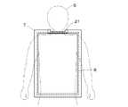
図3は静止画撮影モードにおいて、撮影部7をX線管5側から見た正面図を示しており、一点鎖線は被写体Sを示している。撮影部7の上方の短辺の中央には顎受部21が設けられ、被写体Sの顎が直接触れるようになっている。例えば、顎受部21はひんやりとした不快感を与えないように、金属以外の素材で構成したり、消毒のために布で拭き易い形状とされている。更に、この顎受部21は撮影部7の外形をえぐった形状とすることが多い。これにより、被写体Sの顎と撮影部7の筐体との干渉を防ぎ、被写体Sの肩部周辺までを検出領域に納めることが容易になる。 FIG. 3 shows a front view of the photographing
図3で示す配置において静止画撮影を行えば、被写体Sの胸部、特に肺野のX線画像を取得するために最適となる。撮影部7に内在する破線で示すX線検出器8は平面型固体検出器であり、例えば画素及び薄膜トランジスタ(TFT)から成るX線検出素子を列及び行にアレイ状に二次元的に配列して構成されている。 If still image shooting is performed in the arrangement shown in FIG. 3, it is optimal for obtaining an X-ray image of the chest of the subject S, particularly the lung field. An
一般に、X線検出器は配列の効率の良さから矩形形状の検出領域を有している。正方形の検出領域を有する場合もあるが、本実施例のX線検出器8は平面状で長辺と短辺の長さの異なる二辺を有する矩形形状の検出領域を有している。検出領域の形状に伴って、X線検出器8の外形も長辺と短辺の長さが異なる二辺を有する矩形形状になっている。これらを内蔵する撮影部7についても、同様に長辺と短辺の長さが異なる二辺を有する矩形形状の外形を有している。これは撮影の自由度を高めるために、検出領域以外の無駄な部分をできる限り小さくした外形であることが有利のためである。 In general, the X-ray detector has a rectangular detection region because of the efficiency of arrangement. Although there may be a square detection region, the
X線検出器8のX線検出領域や撮影部7の外形が、長辺と短辺の長さが異なる二辺を有し、これらを90゜回転させることにより、CT撮影での検出領域の横幅を大きくしたい要求と、静止画撮影での横幅を大きくしたくないとの矛盾する制約を解消できる。 The X-ray detection area of the
胸部の静止画撮影の場合には、被写体Sを配置した際に、X線検出器8の検出領域の長辺が、被写体Sの体軸と平行な第1の姿勢となるように設定する。また、CBCT撮影の場合には、X線検出器8の検出領域の短辺が、被写体Sの体軸と平行な第2の姿勢となるように設定することにより、上述の矛盾を解消することができる。なお、静止画撮影の場合であっても、撮影部位又は被写体Sの姿勢によっては、第2の姿勢とすることもある。 In the case of still image shooting of the chest, when the subject S is arranged, the long side of the detection region of the
胸部の静止画撮影において、肺野を検出領域に有効に納めるためには、肩幅方向の検出領域は約350mm以上必要とされている。また上述したように、小柄な被写体Sの場合には、肩から腕が撮影部7と干渉してしまうため、サイズが大き過ぎても好ましくない。一方、体軸方向の撮影部7のサイズについては、上述した顎受部21の干渉以外の制約はなく、大きくても特に支障はない。 In still image shooting of the chest, in order to effectively fit the lung field in the detection area, the detection area in the shoulder width direction is required to be about 350 mm or more. Further, as described above, in the case of the small subject S, since the arm interferes with the photographing
図4は撮影部7を支持する支持部の内部拡大断面図であり、X線検出器8を内蔵する撮影部7の被写体Sと反射側の背面は、基台部22に取り付けられ、更に架台6に対して上下動可能な受部23を介して架台6に取り付けられている。基台部22の前後端にフランジ部22a、22bがそれぞれ設けられ、これらの間に断面コ字型形状の凹部22cが形成され軸部22dとされている。凹部22cには、複数個のベアリング24を介して受部23のフランジ部23aが取り付けられている。また、受部23内に位置するフランジ部22bの外縁部には外歯歯車22eが形成され、この外歯歯車22eに歯車25が噛合され、歯車25にはモータ26の出力軸が連結されている。 FIG. 4 is an enlarged cross-sectional view of the inside of the support unit that supports the
更に、フランジ部22aの壁面22fにはチョッパ27が設けられ、このチョッパ27と対向する位置の受部23のフランジ部23aの2個所には、撮影部姿勢検出手段9に相当するフォトインタラプタ28a、28bが設けられている。 Further, a
図5は図4のZ−Z線に沿った断面図であり、フォトインタラプタ28bはフォトインタラプタ28aから反時計方向に90°回転した位置に設けられている。 FIG. 5 is a cross-sectional view taken along the line ZZ in FIG. 4, and the
更に、X線検出器8、モータ26、フォトインタラプタ28a、27bにはケーブル29が接続され、受部23に穿けられた孔部23bを介して架台6内に配線されている。これらのケーブル29は撮影部7及び受部23に内在するX線検出器8、モータ26、フォトインタラプタ28a、28b等の機器を駆動させ、また画像転送、信号通信等を行うためのものであり、架台6の内部を通ってシステム制御部13等に接続されている。 Further, a
フランジ部22a、22b、軸部22d、外歯歯車22eは軸対称形状な部分を有する部位であり、これらの中心軸は装置のX線検出面に垂直な方向に設定されている。基台部22を支持する受部23は、軸部22dに対向する内筒壁面23cを有しており、この内筒壁面23cが軸受として機能する。基台部22と受部23の間に多数のベアリング24が介在され、軸受機能として円滑な軸回転を実現する。ベアリング24を用いる機構の代りとして、一般の各種軸受と同様に、円筒面や円錐面を持つコロを使用してもよいし、滑り軸受や流体軸受等と同様の構成でも同じ効果が得られる。 The
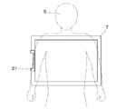
この回転機構により、撮影部7はX線検出面に垂直な軸部22dを中心に回転可能になり、図5に示す撮影部7、7’のように被写体Sに対する相対的な姿勢を変えることが可能となる。特に、図6に示すように、撮影部7を被写体Sの体軸と検出領域の短辺が平行になるように回転させれば、CBCT撮影モードでの撮影において、被写体Sの胴部の全てを投影した画像を得ることに有利になる。CBCT撮影モードにおいては、被写体Sと撮影部7の接触は通常想定されないため、撮影部7の横幅サイズを小さく抑える必要はない。従って、上述のような制約のある短辺方向サイズとは異なり、長辺方向サイズは必要に応じて、長く設定することが可能となる。 By this rotation mechanism, the
基台部22の外歯歯車22eは、モータ26の出力軸に設けられた歯車25と噛合しており、モータ26の回転により基台部22を回転させることが可能になっている。また、モータ26はケーブル29を介して制御部13に電気的に接続され、必要に応じた駆動制御を行うことができる。 The
本実施例においては、撮影部7の姿勢を360°回転可能にしているが、図3で示す位置関係と図6で示す位置関係が実現可能な少なくとも90°回転可能な自由度があれば、大方の要求に応えることは可能である。 In the present embodiment, the posture of the photographing
フォトインタラプタ28a、28bは撮影部7の90゜の回転に相当する位置に配置され、チョッパ27はフォトインタラプタ28a、28bと対向する位置に接近したときに、フォトインタラプタ28a、28bの光路を遮ぎるようになっている。フォトインタラプタ28a又は28bが、チョッパ27によって光路を遮ぎられたとき、オン信号をシステム制御部13に送信する。フォトインタラプタ28a又は28bと、チョッパ27とが離れるとオン信号の送信は停止又はオフ信号の送信を開始する。 The
図5に示すような撮影部7の姿勢の際には、チョッパ27がフォトインタラプタ28aを反応させるよう設定されている。即ち、撮影部7の外形の長辺が被写体Sの体軸と平行で、かつ顎受部21が上向きの位置となるときに、フォトインタラプタ28aとチョッパ27の位置が一致するように設けられている。かくすることにより、システム制御部13が顎受部21の上向きの位置にあることを把握可能になる。 In the posture of the photographing
また、フォトインタラプタ28bとチョッパ27の位置が一致するときは、図6に示すように被写体Sの体軸と検出領域の短辺が平行になるような状態であり、これもシステム制御部13が把握可能にすることができる。 When the positions of the
本実施例においては、フォトインタラプタ28a、28bを用いたが、これらの代りに電気的なスイッチを用いても同様の効果が得られる。その場合には、フォトインタラプタ28a、28bの位置にそれぞれスイッチを設けると共に、フォトインタラプタ28a、28bの位置に代りのスイッチを押すための部材を設ければよい。 In this embodiment, the
また、本実施例において図示は省略しているが、不意に撮影部7が軸部22dを中心に回転して姿勢を変化することのないように、ロック機構を設けてもよい。ロック機構を設けることにより、仮に被写体Sが撮影部7に接触した場合でも、より安定した状態で撮影が可能となる。 Although not shown in the present embodiment, a lock mechanism may be provided to prevent the photographing
図7、図8は上述のX線撮影装置における撮影工程のフローチャート図である。先ず、ステップS1において、X線撮影装置の電源をオンすると、ステップS2において、CBCT撮影モードと静止画撮影モードの何れかを選択する。CBCT撮影モードが選択された場合にはステップS3に進み、図8に示すフローチャート図に移行する。 7 and 8 are flowcharts of imaging steps in the above-described X-ray imaging apparatus. First, when the power of the X-ray imaging apparatus is turned on in step S1, either the CBCT imaging mode or the still image imaging mode is selected in step S2. If the CBCT imaging mode is selected, the process proceeds to step S3, and the process proceeds to the flowchart shown in FIG.
ステップS2において、CBCT撮影モードを選択されていない場合にはステップS4に進み、静止画撮影モードを選択することになる。続いて、ステップS5で、各種撮影パラメータの設定を行った後に、ステップS6で被写体Sの体軸方向とX線検出器8の検出領域の短辺が平行か否かを判断する。フォトインタラプタ28bからの出力信号をチェックし、オン状態である場合には、被写体Sの体軸とX線検出器8の検出領域の短辺が平行であると判断する。これらの場合は撮影を許可して、ステップS11に進む。 In step S2, if the CBCT imaging mode is not selected, the process proceeds to step S4, and the still image imaging mode is selected. Subsequently, after setting various imaging parameters in step S5, it is determined in step S6 whether or not the body axis direction of the subject S and the short side of the detection region of the
また、ステップS6によって、被写体Sの体軸方向と撮影部7の検出領域の短辺が平行でないと判断された場合は、ステップS7に進み、フォトインタラプタ28aからの出力信号をチェックし、検出領域の長辺が平行であるか否かを判断する。平行であると判断された場合はステップS11に進む。 If it is determined in step S6 that the body axis direction of the subject S and the short side of the detection area of the photographing
ステップS7において、フォトインタラプタ28aがオフ状態である場合には、被写体Sの体軸とX線検出器8の検出領域の矩形状の何れの辺とも平行でない状態であると判断する。このことは、一般的に画角に対して納まりの良くない画像を出力することになるためステップS8に進み、警告発信手段を介して表示部12に確認のための警告を表示する。これにより、意図せずに撮影部7を動かして姿勢を変えてしまって、そのまま撮影することを事前に防止できる。 In step S7, when the
ステップS9においては、この例外的撮影を許可するか否かを入力し、操作者が納得してそのままの撮影を許可する場合は、撮影の継続ということにより、先のステップS11へ進む。許可しない場合は、ステップS10で操作者が撮影部7の姿勢の変更を行う。なお、撮影部7の姿勢の変更はモータ26を回転させる制御を行うために、入力部14から指示を入力するか、或いは手動で撮影部7の姿勢を変更した後にステップS6に戻る。 In step S9, whether or not to allow this exceptional shooting is input. If the operator is satisfied and the shooting is allowed as it is, the process proceeds to the previous step S11 by continuing the shooting. If not permitted, the operator changes the posture of the photographing
つまり、ステップS6、S7のチェックでフォトインタラプタ28a、28bの何れかがオン状態になっていれば、次のステップS11に進む。そして、ステップS11においては、表示部12に警告が出ていれば解除し、また表示部12に被写体Sの配置準備ができたことを伝える「被写体のセッティングを開始してください」等のメッセージを表示する。 That is, if any of the
ステップS12において、被写体Sを被写体搭載部1に配置し、ステップS13で撮影開始指令が入力されたか否かを判断する。そして、操作者が入力部14を介して撮影開始指令を入力すると、ステップS14に進み、X線管5から被写体Sに向けて所定の照射条件によるX線が照射され、ステップS15でX線検出器8によるX線投影像の検出が行われる。X線撮影の検出が終了すると、ステップS16に進み、直ちにX線の照射を停止し撮影を終了する。 In step S12, the subject S is placed on the
一方、ステップS15において検出された画像データは、ステップS17でデータ収集部10に送信・格納された後に、ステップS18において処理部11によって適切な画像処理が行われる。続いて、ステップS19に進み、ステップS18で画像処理の施された処理済みの取得画像を表示部12に表示することにより、操作者は診断・観察等に必要な情報を得ることができる。 On the other hand, the image data detected in step S15 is transmitted and stored in the
また、ステップS3において、CBCT撮影モードと選択された場合には、図8のステップS20で、入力部14を介して各種撮影パラメータの設定を行った後に、ステップS21に進み、フォトインタラプタ28bからの出力信号をチェックする。フォトインタラプタ28bがオン状態であれば、被写体Sの体軸方向とX線検出器8の検出領域の短辺が平行であり、CBCT撮影に適切な状態であるため、ステップS22に進む。 If the CBCT imaging mode is selected in step S3, various imaging parameters are set via the
ステップS21において、フォトインタラプタ28bがオフ状態で被写体Sの体軸方向と検出領域の短辺が平行でないと判断された場合は、ステップS23でモータ26を回転駆動する制御を開始する。続いてステップS24において、X線検出器8の検出領域の短辺と被写体Sの体軸方向が平行か否かを判断する。なお、被写体Sの体軸方向と検出領域の短辺が平行でないと判断された場合には、平行になるまでステップS23、S24を繰り返す。フォトインタラプタ28bがオン状態になったところで、ステップS25に進みモータ26の回転駆動を停止する。 If it is determined in step S21 that the
これにより、CBCT撮影に適切な状態となったため、ステップS22に進み、操作者に分かり易くするために、表示部12に「被写体のセッティングを開始してください」等のメッセージを表示する。 As a result, since the state is appropriate for CBCT imaging, the process proceeds to step S22, and a message such as “Please start subject setting” is displayed on the
ステップS26で操作者により被写体支持具4を用いて被写体搭載部1への被写体Sの配置が行われる。ステップS27において、操作者が入力部14より撮影開始指令を入力されたか否かを判断し、撮影開始指令が入力されると、ステップS28に進み、駆動部2がターンテーブル3の回転駆動を開始して加速する。 In step S <b> 26, the operator places the subject S on the
ステップS29で、ターンテーブル3が所定の回転速度に達したか否かを判断し、所定の回転速度に達したと判断された場合にはステップS30に進む。なお、ステップS29においてターンテーブル3が所定の速度に達していないと判断された場合には、所定の速度に達するまでステップS29を繰り返す。 In step S29, it is determined whether or not the
ステップS30において、X線管5から被写体Sに向けて所定の照射条件によるX線が照射する。続いて、ステップS31で、同時にX線検出器8によるX線投影像の検出が開始され、X線照射領域内に配置された被写体Sの部位及び被写体支持具4のX線投影画像データが、ターンテーブル3の所定角度毎に次々と検出される。 In step S30, X-rays are irradiated from the
そして、ステップS32において、全てのX線投影画像データを検出したか否かを判断する。つまり、被写体Sの撮影が開始されてから、ターンテーブル3が360°回転し、1回の撮影分の全てのX線投影画像データの検出が終了すると、ステップS33に進む。ステップS33で、直ちにX線の照射が停止され、同時に駆動部2がターンテーブル3の回転を減速・停止させ、撮影の一連のフローが終了する。 In step S32, it is determined whether or not all X-ray projection image data has been detected. That is, after the imaging of the subject S is started, the
ステップS31において、ターンテーブル3の所定角度毎に検出された多数の画像データは、ステップS34でデータ収集部10に送信・格納され、ステップS35で処理部11によって画像データの再構成処理が行われる。そして、ステップS35において、再構成処理された所定の断層画像や三次元画像は、ステップS36で表示部12に表示され、操作者は診断・観察等に必要な情報を得ることができる。 In step S31, a large number of image data detected for each predetermined angle of the
なお、本実施例においては、モータ26により自動で撮影部7の姿勢を変更できる構成としたが、装置の簡素化・コスト削減するために、モータ26を省略して手動で撮影部7の姿勢を変更できる装置も考えられる。その場合には、ステップS23でモータ26の回転をさせる代りに、表示部12に「撮影部の姿勢を変えて下さい」等のメッセージを表示することで、同様の効果が得られるフローを実現することができる。 In the present embodiment, the posture of the photographing
このように、本実施例におけるX線撮影装置においては、X線検出器8の検出領域の長辺が被写体Sの体軸に平行する第1の姿勢と、検出領域の短辺が被写体Sの体軸に平行する第2の姿勢との少なくとも2つの姿勢を任意に選択可能である。これにより、CT撮影及び静止画撮影を兼用可能となり、CT撮影及び静止画撮影の何れの撮影方法においても、好ましい撮影条件において撮影可能となる。 Thus, in the X-ray imaging apparatus according to the present embodiment, the first posture in which the long side of the detection region of the
上述の説明においては、静止しているX線管5及びX線検出器8から成る撮影系により、ターンテーブル3上の被写体Sを回転運動させて撮影するCT撮影の形態について説明した。しかし、同様のCT撮影は撮影系と被写体との相対運動が行われることによって同様に成り立つため、回転運動する部位が逆でも支障はない。即ち、被写体S側が静止状態であって、被写体Sの周囲をX線管5とX線検出器8の双方を支持しているCアームに代表される支持体を相対的に回転させてもよい。この場合には、被写体Sを固定するターンテーブル3は必要なく、駆動部2はX線管5と撮影部7を共に支えている支持体に接続されていて回転動力を伝達すればよい。このような所謂一般のCアーム式撮影装置におけるCT撮影においても、本発明を適用可能である。 In the above description, the CT imaging mode in which the subject S on the
1 被写体搭載部
2 駆動部
3 ターンテーブル
4 被写体支持具
5 X線管
6 架台
7 撮影部
8 X線検出器
9 撮影部姿勢検出手段
10 データ収集部
11 処理部
12 表示部
13 システム制御部
14 入力部
21 顎受部
22 基台部
22a、22b、23a フランジ部
22c 凹部
22d 軸部
22e 外歯歯車
22f 壁面
23 受部
23b 孔部
23c 内筒壁面
24 ベアリング
25 歯車
26 モータ
27 チョッパ
28a、28b フォトインタラプタ
29 ケーブルDESCRIPTION OF
Claims (3)
Translated fromJapanesePriority Applications (3)
| Application Number | Priority Date | Filing Date | Title |
|---|---|---|---|
| JP2008205689AJP2010035984A (en) | 2008-08-08 | 2008-08-08 | X-ray imaging apparatus |
| US12/537,118US8019045B2 (en) | 2008-08-08 | 2009-08-06 | X-ray imaging apparatus |
| US13/211,037US8630389B2 (en) | 2008-08-08 | 2011-08-16 | X-ray imaging apparatus |
Applications Claiming Priority (1)
| Application Number | Priority Date | Filing Date | Title |
|---|---|---|---|
| JP2008205689AJP2010035984A (en) | 2008-08-08 | 2008-08-08 | X-ray imaging apparatus |
Related Child Applications (1)
| Application Number | Title | Priority Date | Filing Date |
|---|---|---|---|
| JP2014009520ADivisionJP2014064958A (en) | 2014-01-22 | 2014-01-22 | X-ray imaging apparatus, c-arm imaging apparatus, control method and program |
Publications (2)
| Publication Number | Publication Date |
|---|---|
| JP2010035984Atrue JP2010035984A (en) | 2010-02-18 |
| JP2010035984A5 JP2010035984A5 (en) | 2011-09-15 |
Family
ID=41652965
Family Applications (1)
| Application Number | Title | Priority Date | Filing Date |
|---|---|---|---|
| JP2008205689APendingJP2010035984A (en) | 2008-08-08 | 2008-08-08 | X-ray imaging apparatus |
Country Status (2)
| Country | Link |
|---|---|
| US (2) | US8019045B2 (en) |
| JP (1) | JP2010035984A (en) |
Families Citing this family (143)
| Publication number | Priority date | Publication date | Assignee | Title |
|---|---|---|---|---|
| US10357184B2 (en) | 2012-06-21 | 2019-07-23 | Globus Medical, Inc. | Surgical tool systems and method |
| US10653497B2 (en) | 2006-02-16 | 2020-05-19 | Globus Medical, Inc. | Surgical tool systems and methods |
| US10893912B2 (en) | 2006-02-16 | 2021-01-19 | Globus Medical Inc. | Surgical tool systems and methods |
| JP2010035984A (en)* | 2008-08-08 | 2010-02-18 | Canon Inc | X-ray imaging apparatus |
| US20110145741A1 (en)* | 2009-12-16 | 2011-06-16 | Siemens Medical Solutions Usa, Inc. | Context Specific X-ray Imaging User Guidance System |
| US8690426B2 (en)* | 2010-06-14 | 2014-04-08 | General Electric Company | Position sensing device for a portable detection device |
| US9308050B2 (en) | 2011-04-01 | 2016-04-12 | Ecole Polytechnique Federale De Lausanne (Epfl) | Robotic system and method for spinal and other surgeries |
| US11045267B2 (en) | 2012-06-21 | 2021-06-29 | Globus Medical, Inc. | Surgical robotic automation with tracking markers |
| US11607149B2 (en) | 2012-06-21 | 2023-03-21 | Globus Medical Inc. | Surgical tool systems and method |
| US12262954B2 (en) | 2012-06-21 | 2025-04-01 | Globus Medical, Inc. | Surgical robotic automation with tracking markers |
| US10799298B2 (en) | 2012-06-21 | 2020-10-13 | Globus Medical Inc. | Robotic fluoroscopic navigation |
| US11786324B2 (en) | 2012-06-21 | 2023-10-17 | Globus Medical, Inc. | Surgical robotic automation with tracking markers |
| US11253327B2 (en) | 2012-06-21 | 2022-02-22 | Globus Medical, Inc. | Systems and methods for automatically changing an end-effector on a surgical robot |
| EP2863827B1 (en) | 2012-06-21 | 2022-11-16 | Globus Medical, Inc. | Surgical robot platform |
| US11864745B2 (en) | 2012-06-21 | 2024-01-09 | Globus Medical, Inc. | Surgical robotic system with retractor |
| US12004905B2 (en) | 2012-06-21 | 2024-06-11 | Globus Medical, Inc. | Medical imaging systems using robotic actuators and related methods |
| US10646280B2 (en) | 2012-06-21 | 2020-05-12 | Globus Medical, Inc. | System and method for surgical tool insertion using multiaxis force and moment feedback |
| US11896446B2 (en) | 2012-06-21 | 2024-02-13 | Globus Medical, Inc | Surgical robotic automation with tracking markers |
| US12310683B2 (en) | 2012-06-21 | 2025-05-27 | Globus Medical, Inc. | Surgical tool systems and method |
| US10136954B2 (en) | 2012-06-21 | 2018-11-27 | Globus Medical, Inc. | Surgical tool systems and method |
| US10842461B2 (en) | 2012-06-21 | 2020-11-24 | Globus Medical, Inc. | Systems and methods of checking registrations for surgical systems |
| US12329593B2 (en) | 2012-06-21 | 2025-06-17 | Globus Medical, Inc. | Surgical robotic automation with tracking markers |
| US11298196B2 (en) | 2012-06-21 | 2022-04-12 | Globus Medical Inc. | Surgical robotic automation with tracking markers and controlled tool advancement |
| US20150032164A1 (en) | 2012-06-21 | 2015-01-29 | Globus Medical, Inc. | Methods for Performing Invasive Medical Procedures Using a Surgical Robot |
| US11974822B2 (en) | 2012-06-21 | 2024-05-07 | Globus Medical Inc. | Method for a surveillance marker in robotic-assisted surgery |
| US12220120B2 (en) | 2012-06-21 | 2025-02-11 | Globus Medical, Inc. | Surgical robotic system with retractor |
| US11116576B2 (en) | 2012-06-21 | 2021-09-14 | Globus Medical Inc. | Dynamic reference arrays and methods of use |
| US11395706B2 (en) | 2012-06-21 | 2022-07-26 | Globus Medical Inc. | Surgical robot platform |
| US11857266B2 (en) | 2012-06-21 | 2024-01-02 | Globus Medical, Inc. | System for a surveillance marker in robotic-assisted surgery |
| US11317971B2 (en) | 2012-06-21 | 2022-05-03 | Globus Medical, Inc. | Systems and methods related to robotic guidance in surgery |
| US10231791B2 (en) | 2012-06-21 | 2019-03-19 | Globus Medical, Inc. | Infrared signal based position recognition system for use with a robot-assisted surgery |
| US10874466B2 (en) | 2012-06-21 | 2020-12-29 | Globus Medical, Inc. | System and method for surgical tool insertion using multiaxis force and moment feedback |
| US10758315B2 (en) | 2012-06-21 | 2020-09-01 | Globus Medical Inc. | Method and system for improving 2D-3D registration convergence |
| US11864839B2 (en) | 2012-06-21 | 2024-01-09 | Globus Medical Inc. | Methods of adjusting a virtual implant and related surgical navigation systems |
| US11963755B2 (en) | 2012-06-21 | 2024-04-23 | Globus Medical Inc. | Apparatus for recording probe movement |
| US10350013B2 (en) | 2012-06-21 | 2019-07-16 | Globus Medical, Inc. | Surgical tool systems and methods |
| US10624710B2 (en) | 2012-06-21 | 2020-04-21 | Globus Medical, Inc. | System and method for measuring depth of instrumentation |
| US11857149B2 (en) | 2012-06-21 | 2024-01-02 | Globus Medical, Inc. | Surgical robotic systems with target trajectory deviation monitoring and related methods |
| US11589771B2 (en) | 2012-06-21 | 2023-02-28 | Globus Medical Inc. | Method for recording probe movement and determining an extent of matter removed |
| US11399900B2 (en) | 2012-06-21 | 2022-08-02 | Globus Medical, Inc. | Robotic systems providing co-registration using natural fiducials and related methods |
| US11793570B2 (en) | 2012-06-21 | 2023-10-24 | Globus Medical Inc. | Surgical robotic automation with tracking markers |
| US9283048B2 (en) | 2013-10-04 | 2016-03-15 | KB Medical SA | Apparatus and systems for precise guidance of surgical tools |
| US9241771B2 (en) | 2014-01-15 | 2016-01-26 | KB Medical SA | Notched apparatus for guidance of an insertable instrument along an axis during spinal surgery |
| WO2015121311A1 (en) | 2014-02-11 | 2015-08-20 | KB Medical SA | Sterile handle for controlling a robotic surgical system from a sterile field |
| JP2015167603A (en)* | 2014-03-05 | 2015-09-28 | コニカミノルタ株式会社 | Imaging stand |
| EP3134022B1 (en) | 2014-04-24 | 2018-01-10 | KB Medical SA | Surgical instrument holder for use with a robotic surgical system |
| CN106999248B (en) | 2014-06-19 | 2021-04-06 | Kb医疗公司 | Systems and methods for performing minimally invasive surgery |
| US10765438B2 (en) | 2014-07-14 | 2020-09-08 | KB Medical SA | Anti-skid surgical instrument for use in preparing holes in bone tissue |
| US10357257B2 (en) | 2014-07-14 | 2019-07-23 | KB Medical SA | Anti-skid surgical instrument for use in preparing holes in bone tissue |
| EP3226781B1 (en) | 2014-12-02 | 2018-08-01 | KB Medical SA | Robot assisted volume removal during surgery |
| US10013808B2 (en) | 2015-02-03 | 2018-07-03 | Globus Medical, Inc. | Surgeon head-mounted display apparatuses |
| KR102340197B1 (en)* | 2015-02-03 | 2021-12-16 | 삼성전자주식회사 | X ray apparatus and method of oprating the same |
| WO2016131903A1 (en) | 2015-02-18 | 2016-08-25 | KB Medical SA | Systems and methods for performing minimally invasive spinal surgery with a robotic surgical system using a percutaneous technique |
| US10646298B2 (en) | 2015-07-31 | 2020-05-12 | Globus Medical, Inc. | Robot arm and methods of use |
| US10058394B2 (en) | 2015-07-31 | 2018-08-28 | Globus Medical, Inc. | Robot arm and methods of use |
| US10080615B2 (en) | 2015-08-12 | 2018-09-25 | Globus Medical, Inc. | Devices and methods for temporary mounting of parts to bone |
| JP6894431B2 (en) | 2015-08-31 | 2021-06-30 | ケービー メディカル エスアー | Robotic surgical system and method |
| US10034716B2 (en) | 2015-09-14 | 2018-07-31 | Globus Medical, Inc. | Surgical robotic systems and methods thereof |
| US9771092B2 (en) | 2015-10-13 | 2017-09-26 | Globus Medical, Inc. | Stabilizer wheel assembly and methods of use |
| US11883217B2 (en) | 2016-02-03 | 2024-01-30 | Globus Medical, Inc. | Portable medical imaging system and method |
| US10448910B2 (en) | 2016-02-03 | 2019-10-22 | Globus Medical, Inc. | Portable medical imaging system |
| US11058378B2 (en) | 2016-02-03 | 2021-07-13 | Globus Medical, Inc. | Portable medical imaging system |
| US10117632B2 (en) | 2016-02-03 | 2018-11-06 | Globus Medical, Inc. | Portable medical imaging system with beam scanning collimator |
| US10842453B2 (en) | 2016-02-03 | 2020-11-24 | Globus Medical, Inc. | Portable medical imaging system |
| US10866119B2 (en) | 2016-03-14 | 2020-12-15 | Globus Medical, Inc. | Metal detector for detecting insertion of a surgical device into a hollow tube |
| EP3241518B1 (en) | 2016-04-11 | 2024-10-23 | Globus Medical, Inc | Surgical tool systems |
| US11039893B2 (en) | 2016-10-21 | 2021-06-22 | Globus Medical, Inc. | Robotic surgical systems |
| EP3351202B1 (en) | 2017-01-18 | 2021-09-08 | KB Medical SA | Universal instrument guide for robotic surgical systems |
| JP7233841B2 (en) | 2017-01-18 | 2023-03-07 | ケービー メディカル エスアー | Robotic Navigation for Robotic Surgical Systems |
| JP7583513B2 (en) | 2017-01-18 | 2024-11-14 | ケービー メディカル エスアー | Universal instrument guide for robotic surgical systems, surgical instrument system |
| US11071594B2 (en) | 2017-03-16 | 2021-07-27 | KB Medical SA | Robotic navigation of robotic surgical systems |
| US20180289432A1 (en) | 2017-04-05 | 2018-10-11 | Kb Medical, Sa | Robotic surgical systems for preparing holes in bone tissue and methods of their use |
| US11135015B2 (en) | 2017-07-21 | 2021-10-05 | Globus Medical, Inc. | Robot surgical platform |
| US11357548B2 (en) | 2017-11-09 | 2022-06-14 | Globus Medical, Inc. | Robotic rod benders and related mechanical and motor housings |
| US11794338B2 (en) | 2017-11-09 | 2023-10-24 | Globus Medical Inc. | Robotic rod benders and related mechanical and motor housings |
| EP3492032B1 (en) | 2017-11-09 | 2023-01-04 | Globus Medical, Inc. | Surgical robotic systems for bending surgical rods |
| US11134862B2 (en) | 2017-11-10 | 2021-10-05 | Globus Medical, Inc. | Methods of selecting surgical implants and related devices |
| US20190254753A1 (en) | 2018-02-19 | 2019-08-22 | Globus Medical, Inc. | Augmented reality navigation systems for use with robotic surgical systems and methods of their use |
| US10573023B2 (en) | 2018-04-09 | 2020-02-25 | Globus Medical, Inc. | Predictive visualization of medical imaging scanner component movement |
| US11337742B2 (en) | 2018-11-05 | 2022-05-24 | Globus Medical Inc | Compliant orthopedic driver |
| US11278360B2 (en) | 2018-11-16 | 2022-03-22 | Globus Medical, Inc. | End-effectors for surgical robotic systems having sealed optical components |
| US11744655B2 (en) | 2018-12-04 | 2023-09-05 | Globus Medical, Inc. | Drill guide fixtures, cranial insertion fixtures, and related methods and robotic systems |
| US11602402B2 (en) | 2018-12-04 | 2023-03-14 | Globus Medical, Inc. | Drill guide fixtures, cranial insertion fixtures, and related methods and robotic systems |
| US11918313B2 (en) | 2019-03-15 | 2024-03-05 | Globus Medical Inc. | Active end effectors for surgical robots |
| US11571265B2 (en) | 2019-03-22 | 2023-02-07 | Globus Medical Inc. | System for neuronavigation registration and robotic trajectory guidance, robotic surgery, and related methods and devices |
| US11382549B2 (en) | 2019-03-22 | 2022-07-12 | Globus Medical, Inc. | System for neuronavigation registration and robotic trajectory guidance, and related methods and devices |
| US11806084B2 (en) | 2019-03-22 | 2023-11-07 | Globus Medical, Inc. | System for neuronavigation registration and robotic trajectory guidance, and related methods and devices |
| US11317978B2 (en) | 2019-03-22 | 2022-05-03 | Globus Medical, Inc. | System for neuronavigation registration and robotic trajectory guidance, robotic surgery, and related methods and devices |
| US20200297357A1 (en) | 2019-03-22 | 2020-09-24 | Globus Medical, Inc. | System for neuronavigation registration and robotic trajectory guidance, robotic surgery, and related methods and devices |
| US11419616B2 (en) | 2019-03-22 | 2022-08-23 | Globus Medical, Inc. | System for neuronavigation registration and robotic trajectory guidance, robotic surgery, and related methods and devices |
| US11045179B2 (en) | 2019-05-20 | 2021-06-29 | Global Medical Inc | Robot-mounted retractor system |
| US11628023B2 (en) | 2019-07-10 | 2023-04-18 | Globus Medical, Inc. | Robotic navigational system for interbody implants |
| US12396692B2 (en) | 2019-09-24 | 2025-08-26 | Globus Medical, Inc. | Compound curve cable chain |
| US11571171B2 (en) | 2019-09-24 | 2023-02-07 | Globus Medical, Inc. | Compound curve cable chain |
| US12329391B2 (en) | 2019-09-27 | 2025-06-17 | Globus Medical, Inc. | Systems and methods for robot-assisted knee arthroplasty surgery |
| US12408929B2 (en) | 2019-09-27 | 2025-09-09 | Globus Medical, Inc. | Systems and methods for navigating a pin guide driver |
| US11890066B2 (en) | 2019-09-30 | 2024-02-06 | Globus Medical, Inc | Surgical robot with passive end effector |
| US11864857B2 (en) | 2019-09-27 | 2024-01-09 | Globus Medical, Inc. | Surgical robot with passive end effector |
| US11426178B2 (en) | 2019-09-27 | 2022-08-30 | Globus Medical Inc. | Systems and methods for navigating a pin guide driver |
| US11510684B2 (en) | 2019-10-14 | 2022-11-29 | Globus Medical, Inc. | Rotary motion passive end effector for surgical robots in orthopedic surgeries |
| US11992373B2 (en) | 2019-12-10 | 2024-05-28 | Globus Medical, Inc | Augmented reality headset with varied opacity for navigated robotic surgery |
| US12220176B2 (en) | 2019-12-10 | 2025-02-11 | Globus Medical, Inc. | Extended reality instrument interaction zone for navigated robotic |
| US12133772B2 (en) | 2019-12-10 | 2024-11-05 | Globus Medical, Inc. | Augmented reality headset for navigated robotic surgery |
| US12064189B2 (en) | 2019-12-13 | 2024-08-20 | Globus Medical, Inc. | Navigated instrument for use in robotic guided surgery |
| US11464581B2 (en) | 2020-01-28 | 2022-10-11 | Globus Medical, Inc. | Pose measurement chaining for extended reality surgical navigation in visible and near infrared spectrums |
| US11382699B2 (en) | 2020-02-10 | 2022-07-12 | Globus Medical Inc. | Extended reality visualization of optical tool tracking volume for computer assisted navigation in surgery |
| US12414752B2 (en) | 2020-02-17 | 2025-09-16 | Globus Medical, Inc. | System and method of determining optimal 3-dimensional position and orientation of imaging device for imaging patient bones |
| US11207150B2 (en) | 2020-02-19 | 2021-12-28 | Globus Medical, Inc. | Displaying a virtual model of a planned instrument attachment to ensure correct selection of physical instrument attachment |
| US11253216B2 (en) | 2020-04-28 | 2022-02-22 | Globus Medical Inc. | Fixtures for fluoroscopic imaging systems and related navigation systems and methods |
| US11510750B2 (en) | 2020-05-08 | 2022-11-29 | Globus Medical, Inc. | Leveraging two-dimensional digital imaging and communication in medicine imagery in three-dimensional extended reality applications |
| US11153555B1 (en) | 2020-05-08 | 2021-10-19 | Globus Medical Inc. | Extended reality headset camera system for computer assisted navigation in surgery |
| US11382700B2 (en) | 2020-05-08 | 2022-07-12 | Globus Medical Inc. | Extended reality headset tool tracking and control |
| US11317973B2 (en) | 2020-06-09 | 2022-05-03 | Globus Medical, Inc. | Camera tracking bar for computer assisted navigation during surgery |
| US12070276B2 (en) | 2020-06-09 | 2024-08-27 | Globus Medical Inc. | Surgical object tracking in visible light via fiducial seeding and synthetic image registration |
| US11382713B2 (en) | 2020-06-16 | 2022-07-12 | Globus Medical, Inc. | Navigated surgical system with eye to XR headset display calibration |
| US11877807B2 (en) | 2020-07-10 | 2024-01-23 | Globus Medical, Inc | Instruments for navigated orthopedic surgeries |
| US11793588B2 (en) | 2020-07-23 | 2023-10-24 | Globus Medical, Inc. | Sterile draping of robotic arms |
| US11737831B2 (en) | 2020-09-02 | 2023-08-29 | Globus Medical Inc. | Surgical object tracking template generation for computer assisted navigation during surgical procedure |
| US11523785B2 (en) | 2020-09-24 | 2022-12-13 | Globus Medical, Inc. | Increased cone beam computed tomography volume length without requiring stitching or longitudinal C-arm movement |
| US12076091B2 (en) | 2020-10-27 | 2024-09-03 | Globus Medical, Inc. | Robotic navigational system |
| US11911112B2 (en) | 2020-10-27 | 2024-02-27 | Globus Medical, Inc. | Robotic navigational system |
| US11941814B2 (en) | 2020-11-04 | 2024-03-26 | Globus Medical Inc. | Auto segmentation using 2-D images taken during 3-D imaging spin |
| US11717350B2 (en) | 2020-11-24 | 2023-08-08 | Globus Medical Inc. | Methods for robotic assistance and navigation in spinal surgery and related systems |
| US12161433B2 (en) | 2021-01-08 | 2024-12-10 | Globus Medical, Inc. | System and method for ligament balancing with robotic assistance |
| US12150728B2 (en) | 2021-04-14 | 2024-11-26 | Globus Medical, Inc. | End effector for a surgical robot |
| US12178523B2 (en) | 2021-04-19 | 2024-12-31 | Globus Medical, Inc. | Computer assisted surgical navigation system for spine procedures |
| EP4358847A4 (en)* | 2021-06-23 | 2025-05-21 | Kimtron, Inc. | SYSTEM AND METHOD FOR ULTRA-CLOSE PROXIMITY IRRADIATION OF ROTATING BIOMASS |
| US11857273B2 (en) | 2021-07-06 | 2024-01-02 | Globus Medical, Inc. | Ultrasonic robotic surgical navigation |
| US11439444B1 (en) | 2021-07-22 | 2022-09-13 | Globus Medical, Inc. | Screw tower and rod reduction tool |
| US12213745B2 (en) | 2021-09-16 | 2025-02-04 | Globus Medical, Inc. | Extended reality systems for visualizing and controlling operating room equipment |
| US12238087B2 (en) | 2021-10-04 | 2025-02-25 | Globus Medical, Inc. | Validating credential keys based on combinations of credential value strings and input order strings |
| US12184636B2 (en) | 2021-10-04 | 2024-12-31 | Globus Medical, Inc. | Validating credential keys based on combinations of credential value strings and input order strings |
| US20230368330A1 (en) | 2021-10-20 | 2023-11-16 | Globus Medical, Inc. | Interpolation of medical images |
| US20230165639A1 (en) | 2021-12-01 | 2023-06-01 | Globus Medical, Inc. | Extended reality systems with three-dimensional visualizations of medical image scan slices |
| US11911115B2 (en) | 2021-12-20 | 2024-02-27 | Globus Medical Inc. | Flat panel registration fixture and method of using same |
| US12103480B2 (en) | 2022-03-18 | 2024-10-01 | Globus Medical Inc. | Omni-wheel cable pusher |
| US12048493B2 (en) | 2022-03-31 | 2024-07-30 | Globus Medical, Inc. | Camera tracking system identifying phantom markers during computer assisted surgery navigation |
| US12394086B2 (en) | 2022-05-10 | 2025-08-19 | Globus Medical, Inc. | Accuracy check and automatic calibration of tracked instruments |
| US12161427B2 (en) | 2022-06-08 | 2024-12-10 | Globus Medical, Inc. | Surgical navigation system with flat panel registration fixture |
| US20240020840A1 (en) | 2022-07-15 | 2024-01-18 | Globus Medical, Inc. | REGISTRATION OF 3D and 2D IMAGES FOR SURGICAL NAVIGATION AND ROBOTIC GUIDANCE WITHOUT USING RADIOPAQUE FIDUCIALS IN THE IMAGES |
| US12226169B2 (en) | 2022-07-15 | 2025-02-18 | Globus Medical, Inc. | Registration of 3D and 2D images for surgical navigation and robotic guidance without using radiopaque fiducials in the images |
| JP2024030053A (en)* | 2022-08-23 | 2024-03-07 | 富士フイルム株式会社 | computerized tomography device |
| US12318150B2 (en) | 2022-10-11 | 2025-06-03 | Globus Medical Inc. | Camera tracking system for computer assisted surgery navigation |
Citations (2)
| Publication number | Priority date | Publication date | Assignee | Title |
|---|---|---|---|---|
| JP2001145616A (en)* | 1999-11-22 | 2001-05-29 | Toshiba Corp | X-ray diagnostic equipment |
| WO2008035953A1 (en)* | 2006-09-22 | 2008-03-27 | Ray Co., Ltd. | Complex imaging system for dental |
Family Cites Families (4)
| Publication number | Priority date | Publication date | Assignee | Title |
|---|---|---|---|---|
| JP2000116635A (en) | 1998-10-09 | 2000-04-25 | Hitachi Medical Corp | X-ray image diagnostic instrument |
| JP4508789B2 (en) | 2004-09-07 | 2010-07-21 | キヤノン株式会社 | X-ray equipment |
| DK2119326T3 (en)* | 2007-01-24 | 2017-05-22 | Dental Imaging Tech Corp | Adjustable scanner |
| JP2010035984A (en)* | 2008-08-08 | 2010-02-18 | Canon Inc | X-ray imaging apparatus |
- 2008
- 2008-08-08JPJP2008205689Apatent/JP2010035984A/enactivePending
- 2009
- 2009-08-06USUS12/537,118patent/US8019045B2/ennot_activeExpired - Fee Related
- 2011
- 2011-08-16USUS13/211,037patent/US8630389B2/enactiveActive
Patent Citations (2)
| Publication number | Priority date | Publication date | Assignee | Title |
|---|---|---|---|---|
| JP2001145616A (en)* | 1999-11-22 | 2001-05-29 | Toshiba Corp | X-ray diagnostic equipment |
| WO2008035953A1 (en)* | 2006-09-22 | 2008-03-27 | Ray Co., Ltd. | Complex imaging system for dental |
Also Published As
| Publication number | Publication date |
|---|---|
| US20110299660A1 (en) | 2011-12-08 |
| US8019045B2 (en) | 2011-09-13 |
| US20100034346A1 (en) | 2010-02-11 |
| US8630389B2 (en) | 2014-01-14 |
Similar Documents
| Publication | Publication Date | Title |
|---|---|---|
| JP2010035984A (en) | X-ray imaging apparatus | |
| CN101305919B (en) | X-ray imaging apparatus | |
| JP6644807B2 (en) | Rotating yoke mount for intraoral 3D X-ray system | |
| JP4345966B2 (en) | 3D reconstruction system and method using variable distance between X-ray source and image | |
| US8581932B2 (en) | Image display system | |
| WO2008035828A1 (en) | Dental complex imaging system | |
| JP2007029168A (en) | X-ray CT imaging system | |
| US20080025459A1 (en) | X-ray hybrid diagnosis system | |
| JP2007185514A (en) | Imaging medical device and method for setting operation parameters of imaging medical device | |
| JP7071410B2 (en) | X-ray tomography equipment with added scanner function | |
| KR101844515B1 (en) | Portable medical apparatus, and method for controlling portable medical apparatus | |
| WO2008019355A2 (en) | Ct scanner including a camera to obtain external images of a patient | |
| JP2018031656A (en) | Photographing device for diagnostic imaging | |
| CN111432729A (en) | X-ray CT imaging device | |
| KR100990474B1 (en) | Dual Source X-ray CT Shooting Device | |
| WO2017056533A1 (en) | Control device, radiographic imaging apparatus, radiographic imaging method, and radiographic imaging program | |
| JP4044205B2 (en) | X-ray fluoroscopic equipment | |
| JP2015198769A (en) | X-ray CT apparatus | |
| JP2014064958A (en) | X-ray imaging apparatus, c-arm imaging apparatus, control method and program | |
| JP2009201928A (en) | Radiographic imaging system | |
| CN118056530A (en) | Augmented reality-centric cone beam computed tomography | |
| FI125206B (en) | Location of anatomical partial volumes | |
| JP5676883B2 (en) | X-ray CT system | |
| JP4479503B2 (en) | Tomography equipment | |
| KR102246090B1 (en) | Radiology apparatus with FOV enlargement function |
Legal Events
| Date | Code | Title | Description |
|---|---|---|---|
| RD01 | Notification of change of attorney | Free format text:JAPANESE INTERMEDIATE CODE: A7421 Effective date:20100218 | |
| RD01 | Notification of change of attorney | Free format text:JAPANESE INTERMEDIATE CODE: A7421 Effective date:20100630 | |
| A521 | Request for written amendment filed | Free format text:JAPANESE INTERMEDIATE CODE: A523 Effective date:20110801 | |
| A621 | Written request for application examination | Free format text:JAPANESE INTERMEDIATE CODE: A621 Effective date:20110801 | |
| A131 | Notification of reasons for refusal | Free format text:JAPANESE INTERMEDIATE CODE: A131 Effective date:20130129 | |
| A977 | Report on retrieval | Free format text:JAPANESE INTERMEDIATE CODE: A971007 Effective date:20130131 | |
| A521 | Request for written amendment filed | Free format text:JAPANESE INTERMEDIATE CODE: A523 Effective date:20130326 | |
| A131 | Notification of reasons for refusal | Free format text:JAPANESE INTERMEDIATE CODE: A131 Effective date:20130611 | |
| A521 | Request for written amendment filed | Free format text:JAPANESE INTERMEDIATE CODE: A523 Effective date:20130809 | |
| A02 | Decision of refusal | Free format text:JAPANESE INTERMEDIATE CODE: A02 Effective date:20131022 |