JP2010029594A - Corpuscular beam irradiating apparatus and treatment planning device - Google Patents
Corpuscular beam irradiating apparatus and treatment planning deviceDownload PDFInfo
- Publication number
- JP2010029594A JP2010029594AJP2008197706AJP2008197706AJP2010029594AJP 2010029594 AJP2010029594 AJP 2010029594AJP 2008197706 AJP2008197706 AJP 2008197706AJP 2008197706 AJP2008197706 AJP 2008197706AJP 2010029594 AJP2010029594 AJP 2010029594A
- Authority
- JP
- Japan
- Prior art keywords
- scanning
- irradiation
- shape
- particle beam
- beam shape
- Prior art date
- Legal status (The legal status is an assumption and is not a legal conclusion. Google has not performed a legal analysis and makes no representation as to the accuracy of the status listed.)
- Pending
Links
- 230000001678irradiating effectEffects0.000titleabstractdescription8
- 239000002245particleSubstances0.000claimsabstractdescription24
- 238000009826distributionMethods0.000claimsdescription13
- 230000002093peripheral effectEffects0.000claimsdescription2
- 238000010586diagramMethods0.000description6
- 238000000034methodMethods0.000description6
- 206010028980NeoplasmDiseases0.000description3
- 238000003780insertionMethods0.000description3
- 230000037431insertionEffects0.000description3
- 230000005855radiationEffects0.000description3
- 241001465754MetazoaSpecies0.000description1
- 201000011510cancerDiseases0.000description1
- 210000004072lungAnatomy0.000description1
- 238000007726management methodMethods0.000description1
- 210000000056organAnatomy0.000description1
- 238000001959radiotherapyMethods0.000description1
- 238000004904shorteningMethods0.000description1
Images


Landscapes
- Radiation-Therapy Devices (AREA)
Abstract
Translated fromJapaneseDescription
Translated fromJapanese本発明は、粒子線をスキャニング照射するための粒子線照射装置及び治療計画装置に係り、特に、スキャニング照射における照射野半影帯を縮小し、正常組織への線量寄与を小さくすることが可能な粒子線照射装置、及び、この粒子線照射装置に用いる治療計画装置に関する。 The present invention relates to a particle beam irradiation apparatus and a treatment planning apparatus for irradiating a particle beam with scanning, and in particular, can reduce the radiation field penumbra in scanning irradiation and reduce the dose contribution to normal tissue. The present invention relates to a particle beam irradiation apparatus and a treatment planning apparatus used for the particle beam irradiation apparatus.
近年、陽子線、重粒子線等の粒子線を用いた放射線治療装置が注目されている。粒子線の照射法には、照射すべき領域全体を覆うように3次元(横方向x、y、深さ方向z)に拡げたビームを一気に照射する拡大照射法と、3次元的に局所集中した線量分布を持つ粒子線によるスポットビームで腫瘍部(標的部)を3次元的に塗り潰すように照射するスキャニング照射法がある。スキャニング照射で、スポットビームが3次元的に局所集中するスポット位置は、予め治療計画により設定され、横方向と縦方向を水平と垂直の2台の走査電磁石で制御し、深さ方向をエネルギの変更により制御する。これにより複雑な形状の腫瘍部に対しても3次元的形状に合った照射を行なえる。 In recent years, radiotherapy devices using particle beams such as proton beams and heavy particle beams have attracted attention. As the particle beam irradiation method, there is an expanded irradiation method in which a beam expanded in three dimensions (lateral direction x, y, depth direction z) so as to cover the entire region to be irradiated is irradiated at once, and three-dimensional local concentration. There is a scanning irradiation method of irradiating a tumor part (target part) three-dimensionally with a spot beam by a particle beam having a dose distribution. The spot position where the spot beam is locally concentrated three-dimensionally by scanning irradiation is set in advance by a treatment plan, and the horizontal direction and the vertical direction are controlled by two horizontal and vertical scanning magnets, and the depth direction is controlled by energy. Control by change. Thereby, irradiation suitable for a three-dimensional shape can be performed even for a tumor portion having a complicated shape.
従来のスキャニング照射法では、特許文献1に例示されるように、円形で固定のビームサイズで照射を行なっており、拡大照射法に比べて、複雑なターゲット形状に対応し、ビームの照射時間を変えることによって線量分布に濃淡を付けられるという特徴を有する。 In the conventional scanning irradiation method, as illustrated in
しかしながら従来は、照射位置や線量等の管理が複雑になることを避けて、ビームサイズにある程度の大きさのものを用いるため、図1(A)に示す如く、プロードビームに比べて照射野半影帯が大きくなり、正常組織への線量寄与が大きくなるという問題点を有していた。 However, conventionally, since the management of the irradiation position and dose is avoided and the beam size is used to a certain extent, as shown in FIG. There was a problem that the shadow band became larger and the contribution of dose to normal tissues became larger.
なお、特許文献2には、照射対象に応じて複数のスポットビーム径を切り替えることが記載され、特許文献3には、レンジシフタを用いてビームの照射深度を調整することが記載されているが、いずれも1回のスキャニング照射途中でビーム形状を変更するものではなかった。 Note that
本発明は、前記従来の問題点を解決するべくなされたもので、スキャニング照射における照射野半影帯を縮小し、正常組織への線量寄与を小さくすることを課題とする。 The present invention has been made to solve the above-mentioned conventional problems, and an object of the present invention is to reduce the radiation field penumbra in scanning irradiation and reduce the dose contribution to normal tissue.
本発明は、粒子線をスキャニング照射するための粒子線照射装置において、複数のビーム形状を設定するためのビーム形状設定手段と、スキャニング途中でビーム形状を変更するための手段と、を備え、スキャニングポイントに適したビーム形状を選択しながらスキャニング照射することにより、前記課題を解決したものである。 The present invention relates to a particle beam irradiation apparatus for scanning and irradiating a particle beam, comprising: a beam shape setting means for setting a plurality of beam shapes; and a means for changing the beam shape during scanning. The above-mentioned problem is solved by performing scanning irradiation while selecting a beam shape suitable for a point.
ここで、前記ビーム形状設定手段は、複数の深さ形状、複数の断面形状、複数のスポットサイズのいずれか、又は、これらの組合せを設定することができる。 Here, the beam shape setting means can set one of a plurality of depth shapes, a plurality of cross-sectional shapes, a plurality of spot sizes, or a combination thereof.
又、前記ビーム形状設定手段を、コリメータ、散乱体、リッジフィルタ、電磁石、スリットの少なくともいずれかとすることができる。 Further, the beam shape setting means may be at least one of a collimator, a scatterer, a ridge filter, an electromagnet, and a slit.
又、前記ビーム形状を変更する手段を、コリメータ制御装置、散乱体制御装置、フィルタ制御装置の少なくともいずれかとすることができる。 Further, the means for changing the beam shape may be at least one of a collimator control device, a scatterer control device, and a filter control device.
本発明は、又、粒子線を被検体にスキャニング照射する際に用いる治療計画装置において、照射可能な複数のビーム形状を記憶するための手段と、線量分布に応じて、スキャニング途中でビーム形状を変更するように設定するための手段と、を備えたことを特徴とする治療計画装置を提供するものである。 The present invention also provides a treatment planning apparatus for use in scanning irradiation of a particle beam on a subject, a means for storing a plurality of beam shapes that can be irradiated, and a beam shape during scanning according to a dose distribution. Means for setting to change is provided, and a treatment planning apparatus is provided.
ここで、照射野の周辺縁部は小さいビームサイズ、中心部は大きいビームサイズを用いて連続スキャンすることができる。 Here, continuous scanning can be performed using a small beam size at the peripheral edge of the irradiation field and a large beam size at the center.
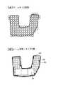
本発明によれば、アイソセンターでのビーム形状(例えばスポットサイズ)を、図1(B)に例示する如く、スキャニング途中でb1、b2、b3、b4と変更することにより、照射野半影帯を縮小して、正常組織への線量寄与を減少することができる。 According to the present invention, the irradiation field penumbra can be obtained by changing the beam shape (for example, spot size) at the isocenter to b1, b2, b3, and b4 in the middle of scanning as illustrated in FIG. Can be reduced to reduce the dose contribution to normal tissue.
以下図面を参照して、本発明の実施形態を詳細に説明する。 Hereinafter, embodiments of the present invention will be described in detail with reference to the drawings.
本発明が適用される治療計画装置及び粒子線照射装置は、図2に示す如く構成される。即ち、まず治療計画装置10で、線量分布に応じて最適なビーム形状を選択し、治療計画を立てる。次に、制御装置20で、ビーム形状変調装置30及びスキャニング照射装置40を制御する。 The treatment planning apparatus and particle beam irradiation apparatus to which the present invention is applied are configured as shown in FIG. That is, first, the
具体的には、図3に示す如く、加速器(図示省略)からのビーム6の形状を、エネルギ変調装置(リッジフィルタ)、コリメータ、電磁石、散乱体、スリット等を含んで構成されるビーム形状変調装置30で変更し、形状変更後のビーム8を、走査電磁石42で走査し、例えば、線量モニタ50を介して患者4に照射する。 Specifically, as shown in FIG. 3, the shape of the
ここで、ビームのスポットサイズ・形状を変更するために、前記ビーム形状変調装置30には、図4及び図5に示すコリメータ32とコリメータ制御装置33が設けられており、このコリメータ制御装置33を制御することによって、スキャニングの途中でビームのスポットサイズ及び断面形状が変更される。形状変更後のビームは、X方向及びY方向の走査電磁石42X、42Yで走査される。 Here, in order to change the spot size / shape of the beam, the beam
又、ビームの断面形状を変更するために、図6に示す如く、例えば2種類の厚さを持つ散乱体34と、そのビームへの挿入位置を制御するための散乱体制御装置35を設けることができる。この場合には、図7に例示する如く、薄い散乱体34aを挿入してビームの深さ方向ピーク形状を鋭くしたり、厚い散乱体34bを挿入してビーム径を大きくすることができる。 In order to change the cross-sectional shape of the beam, as shown in FIG. 6, for example, a scatterer 34 having two types of thickness and a
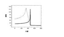
又、ビームの深さ方向の厚み(ブラッグピークの幅)を変更するために、図8に示す如く、例えば3種類の高低差を選択可能なリッジフィルタ36と、そのビームへの挿入位置を変えるためのフィルタ制御装置37を設けることができる。この場合には、図9に例示する如く、高低差が中間のフィルタ36bに対して、高低差が大きなフィルタ36aを挿入してブラッグピークの幅を広げたり、高低差が小さなフィルタ36cを挿入してブラッグピークの幅を狭くすることができる。 Further, in order to change the thickness (Bragg peak width) of the beam in the depth direction, as shown in FIG. 8, for example, a
図9に示したような深さ形状が異なるビームをスキャンして、三次元の照射野を形成する。 A beam having a different depth shape as shown in FIG. 9 is scanned to form a three-dimensional irradiation field.
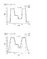
走査ビームの深さ方向線量分布(幾何学的な形状ではなく、一本のビームが寄与する深さ毎の線量)を三角形や四角形に変形した例を、図10(三角形)、図11(四角形)に示す。これらの例のように、専用にデザインされたリッジフィルタを用いることにより、走査ビームの深さ方向線量分布を変化させながら照射野を形成することができる。最適な深さ方向線量分布を持つ走査ビームを用いることにより、スキャニング照射における照射野半影帯を縮小し、正常組織への線量寄与を小さくすることが可能となる。 FIG. 10 (triangle) and FIG. 11 (rectangle) are examples in which the dose distribution in the depth direction of the scanning beam (the dose for each depth contributed by one beam instead of the geometric shape) is transformed into a triangle or a rectangle. ). By using a dedicated ridge filter as in these examples, the irradiation field can be formed while changing the dose distribution in the depth direction of the scanning beam. By using a scanning beam having an optimal dose distribution in the depth direction, it is possible to reduce the radiation penumbra in scanning irradiation and reduce the dose contribution to normal tissue.
図12に、治療計画の流れを示す。ステップ100でCT画像を入力し、ステップ110で照射範囲を決定し、ステップ120で照射方向を決定し、ステップ130で、本発明を行うために照射野の辺縁を探し、ステップ140で、半影帯が小さくなるような、効率的なスポット形状、照射スポットの配置、及び、ウエイトを決定する。 FIG. 12 shows the flow of treatment planning. A CT image is input in
このようにして、図1(B)に例示した如く、スキャニングポイントがビーム垂直面内の照射野辺縁部である場合には、中央部のビームb1に比べてビーム径が小さいビームb2、b3、b4、若しくは照射野の形状に類似した形状のビームを照射し、ビーム深さ方向の照射野辺縁部にはピーク形状が鋭いビームを照射することで、正常組織への線量寄与を減少させることができる。 In this way, as illustrated in FIG. 1B, when the scanning point is the irradiation field edge in the beam vertical plane, the beams b2, b3, which have a smaller beam diameter than the central beam b1. By irradiating a beam having a shape similar to the shape of b4 or the irradiation field and irradiating a beam having a sharp peak shape to the irradiation field edge in the beam depth direction, the dose contribution to the normal tissue can be reduced. it can.
又、スキャニングポイントが照射野中央部の平坦な照射野部分である場合では、ビーム体積の大きなビームを走査させることで、走査スポット数が減り、照射時間を短縮することができる。特に、心臓や肺等の移動性臓器への照射では、照射時間を短縮することにより、正確な線量分布を照射できる。 Further, when the scanning point is a flat irradiation field portion at the center of the irradiation field, the number of scanning spots can be reduced and the irradiation time can be shortened by scanning a beam having a large beam volume. In particular, when irradiating mobile organs such as the heart and lungs, an accurate dose distribution can be irradiated by shortening the irradiation time.
ビームサイズが小さい時(A)と大きい時(B)の線量分布の一例を図13に、ビームサイズを変化させたときの輪郭部の線量分布の一例を図14に示す。 FIG. 13 shows an example of the dose distribution when the beam size is small (A) and when the beam size is large (B), and FIG. 14 shows an example of the dose distribution at the contour when the beam size is changed.
なお、前記実施形態においては、ビームのスポットサイズや断面形状を変更するための手段としてコリメータ、散乱体が用いられ、ビームの深さ形状を変更するための手段としてリッジフィルタが用いられていたが、スポットサイズ、断面形状、深さ形状を変更する手段は、これらに限定されず、例えばスリットや電磁石を用いてスポットサイズや形状を変更することも可能である。又、ビーム形状変調装置の挿入位置も走査電磁石の入側に限定されない。 In the above embodiment, a collimator and a scatterer are used as means for changing the spot size and cross-sectional shape of the beam, and a ridge filter is used as means for changing the depth shape of the beam. The means for changing the spot size, the cross-sectional shape, and the depth shape are not limited to these. For example, the spot size or shape can be changed using a slit or an electromagnet. Further, the insertion position of the beam shape modulation device is not limited to the entrance side of the scanning electromagnet.
更に、図15に示す第2実施形態の如く、ビームプロファイルを検出するための位置モニタ60を設けてビーム位置やビーム径を補正することも可能である。図において、5は、ガン等の病変部、62は、加速器から取り出されたビーム6の飛程を調節するレンジシフタ、64は、ビーム径を変更する四極電磁石である。 Further, as in the second embodiment shown in FIG. 15, a
なお、偏向電磁石として、図では走査電磁石42X、42Yの補正を示しているが、別にステアリング電磁石を設置しても良い。又、電磁石の極数も4に限定されない。 In addition, although correction | amendment of the
更に、照射対象も人間に限定されず、動物であっても良い。 Furthermore, the irradiation target is not limited to humans, and may be animals.
10…治療計画装置
20…制御装置
30…ビーム形状変調装置
32…コリメータ
33…コリメータ制御装置
34…散乱体
35…散乱体制御装置
36…リッジフィルタ
37…フィルタ制御装置
40…スキャニング照射装置
42、42X、42Y…走査電磁石
50…線量モニタ
60…位置モニタ
64…四極電磁石DESCRIPTION OF
Claims (8)
Translated fromJapanese複数のビーム形状を設定するためのビーム形状設定手段と、
スキャニング途中でビーム形状を変更するための手段と、
を備え、
スキャニングポイントに適したビーム形状を選択しながらスキャニング照射することを特徴とする粒子線照射装置。In the particle beam irradiation apparatus for scanning irradiation of particle beam,
Beam shape setting means for setting a plurality of beam shapes;
Means for changing the beam shape during scanning;
With
A particle beam irradiation apparatus that performs scanning irradiation while selecting a beam shape suitable for a scanning point.
照射可能な複数のビーム形状を選択するための手段と、
線量分布に応じて、スキャニング途中でビーム形状を変更するように設定するための手段と、
を備えたことを特徴とする治療計画装置。In a treatment planning device used when scanning irradiation of a particle beam to a subject,
Means for selecting a plurality of beam shapes that can be irradiated;
Means for setting the beam shape to change during scanning according to the dose distribution;
A treatment planning apparatus comprising:
Priority Applications (1)
| Application Number | Priority Date | Filing Date | Title |
|---|---|---|---|
| JP2008197706AJP2010029594A (en) | 2008-07-31 | 2008-07-31 | Corpuscular beam irradiating apparatus and treatment planning device |
Applications Claiming Priority (1)
| Application Number | Priority Date | Filing Date | Title |
|---|---|---|---|
| JP2008197706AJP2010029594A (en) | 2008-07-31 | 2008-07-31 | Corpuscular beam irradiating apparatus and treatment planning device |
Publications (1)
| Publication Number | Publication Date |
|---|---|
| JP2010029594Atrue JP2010029594A (en) | 2010-02-12 |
Family
ID=41734786
Family Applications (1)
| Application Number | Title | Priority Date | Filing Date |
|---|---|---|---|
| JP2008197706APendingJP2010029594A (en) | 2008-07-31 | 2008-07-31 | Corpuscular beam irradiating apparatus and treatment planning device |
Country Status (1)
| Country | Link |
|---|---|
| JP (1) | JP2010029594A (en) |
Cited By (19)
| Publication number | Priority date | Publication date | Assignee | Title |
|---|---|---|---|---|
| JP4673450B1 (en)* | 2010-08-20 | 2011-04-20 | 三菱電機株式会社 | Particle beam irradiation apparatus and particle beam therapy apparatus |
| JP2011212395A (en)* | 2010-04-02 | 2011-10-27 | Mitsubishi Electric Corp | Treatment planning instrument and corpuscular beam therapeutic instrument using treatment planning instrument |
| JP2012040347A (en)* | 2011-01-20 | 2012-03-01 | Mitsubishi Electric Corp | Particle beam irradiation device and particle beam therapy equipment |
| WO2014119050A1 (en)* | 2013-01-29 | 2014-08-07 | 株式会社日立製作所 | Particle-beam therapy system |
| WO2014133139A1 (en)* | 2013-02-28 | 2014-09-04 | 三菱重工業株式会社 | Therapy planning device, system for planned therapy, method for making therapy plan, and program |
| JP2014231020A (en)* | 2014-09-17 | 2014-12-11 | 三菱電機株式会社 | Therapeutic device with particle beam |
| US9084890B2 (en) | 2010-04-02 | 2015-07-21 | Mitsubishi Electric Corporation | Particle beam irradiation apparatus and particle beam therapy system |
| JP2015150184A (en)* | 2014-02-14 | 2015-08-24 | 株式会社日立製作所 | Treatment planning device and storage medium storing arithmetic method for treatment plan |
| WO2016162998A1 (en)* | 2015-04-09 | 2016-10-13 | 三菱電機株式会社 | Therapy planning apparatus and particle radiation therapy apparatus |
| JP2017070851A (en)* | 2017-01-26 | 2017-04-13 | 三菱電機株式会社 | Particle radiotherapy equipment |
| JP2017205215A (en)* | 2016-05-17 | 2017-11-24 | 住友重機械工業株式会社 | Charged particle beam treatment device |
| JP2018143659A (en)* | 2017-03-08 | 2018-09-20 | 住友重機械工業株式会社 | Charged particle beam treatment device |
| CN109803723A (en)* | 2016-07-08 | 2019-05-24 | 梅维昂医疗系统股份有限公司 | Treatment plan |
| JP2019147008A (en)* | 2013-09-27 | 2019-09-05 | メビオン・メディカル・システムズ・インコーポレーテッド | Particle beam scanning |
| US10418141B2 (en) | 2017-07-20 | 2019-09-17 | Sumitomo Heavy Industries, Ltd. | Charged particle beam treatment apparatus |
| JP2020525103A (en)* | 2017-06-30 | 2020-08-27 | レイサーチ ラボラトリーズ,エービー | Determination of variable size spot distribution for ion beam therapy based on user configuration |
| CN113117254A (en)* | 2021-05-18 | 2021-07-16 | 兰州科近泰基新技术有限责任公司 | Beam modulation equipment adaptation device and beam modulation system |
| JP2023519136A (en)* | 2020-03-18 | 2023-05-10 | レイサーチ ラボラトリーズ エービー | Method of generating radiation treatment plan, computer program and computer system for generating radiation treatment plan and radiation therapy delivery system |
| JP2024526940A (en)* | 2021-07-21 | 2024-07-19 | ナショナル キャンサー センター | Transformation device for transforming a treatment beam for treating a lesion in a subject |
Citations (5)
| Publication number | Priority date | Publication date | Assignee | Title |
|---|---|---|---|---|
| JPH10127792A (en)* | 1996-11-01 | 1998-05-19 | Hitachi Ltd | Charged particle beam equipment |
| JP2000084097A (en)* | 1998-09-17 | 2000-03-28 | Mitsubishi Electric Corp | Particle beam energy changing device and particle beam irradiation device |
| JP2001212253A (en)* | 2000-02-03 | 2001-08-07 | Toshiba Corp | Particle beam irradiation method and particle beam irradiation device |
| JP2002191709A (en)* | 2000-12-26 | 2002-07-10 | Toshiba Corp | Particle beam irradiation apparatus and method, and ridge filter |
| US20080123813A1 (en)* | 2006-04-07 | 2008-05-29 | Maurer Calvin R | Automatic selection of multiple collimators |
- 2008
- 2008-07-31JPJP2008197706Apatent/JP2010029594A/enactivePending
Patent Citations (5)
| Publication number | Priority date | Publication date | Assignee | Title |
|---|---|---|---|---|
| JPH10127792A (en)* | 1996-11-01 | 1998-05-19 | Hitachi Ltd | Charged particle beam equipment |
| JP2000084097A (en)* | 1998-09-17 | 2000-03-28 | Mitsubishi Electric Corp | Particle beam energy changing device and particle beam irradiation device |
| JP2001212253A (en)* | 2000-02-03 | 2001-08-07 | Toshiba Corp | Particle beam irradiation method and particle beam irradiation device |
| JP2002191709A (en)* | 2000-12-26 | 2002-07-10 | Toshiba Corp | Particle beam irradiation apparatus and method, and ridge filter |
| US20080123813A1 (en)* | 2006-04-07 | 2008-05-29 | Maurer Calvin R | Automatic selection of multiple collimators |
Cited By (37)
| Publication number | Priority date | Publication date | Assignee | Title |
|---|---|---|---|---|
| US9084890B2 (en) | 2010-04-02 | 2015-07-21 | Mitsubishi Electric Corporation | Particle beam irradiation apparatus and particle beam therapy system |
| JP2011212395A (en)* | 2010-04-02 | 2011-10-27 | Mitsubishi Electric Corp | Treatment planning instrument and corpuscular beam therapeutic instrument using treatment planning instrument |
| US9770604B2 (en) | 2010-04-02 | 2017-09-26 | Mitsubishi Electric Corporation | Particle beam irradiation apparatus and particle beam therapy system |
| WO2012023205A1 (en)* | 2010-08-20 | 2012-02-23 | 三菱電機株式会社 | Particle beam-irradiating device and particle beam therapy device |
| US8604444B2 (en) | 2010-08-20 | 2013-12-10 | Mitsubishi Electric Corporation | Particle beam irradiation apparatus and particle beam therapy system |
| TWI426530B (en)* | 2010-08-20 | 2014-02-11 | Mitsubishi Electric Corp | Particle ray irradiation device and particle ray treatment device |
| JP4673450B1 (en)* | 2010-08-20 | 2011-04-20 | 三菱電機株式会社 | Particle beam irradiation apparatus and particle beam therapy apparatus |
| JP2012040347A (en)* | 2011-01-20 | 2012-03-01 | Mitsubishi Electric Corp | Particle beam irradiation device and particle beam therapy equipment |
| WO2014119050A1 (en)* | 2013-01-29 | 2014-08-07 | 株式会社日立製作所 | Particle-beam therapy system |
| JP2014144122A (en)* | 2013-01-29 | 2014-08-14 | Hitachi Ltd | Particle beam treatment system |
| US9492684B2 (en) | 2013-01-29 | 2016-11-15 | Hitachi, Ltd. | Particle therapy system |
| WO2014133139A1 (en)* | 2013-02-28 | 2014-09-04 | 三菱重工業株式会社 | Therapy planning device, system for planned therapy, method for making therapy plan, and program |
| JP2014166245A (en)* | 2013-02-28 | 2014-09-11 | Mitsubishi Heavy Ind Ltd | Treatment planning device, planning treatment system, treatment plan generation method and program |
| JP2019147008A (en)* | 2013-09-27 | 2019-09-05 | メビオン・メディカル・システムズ・インコーポレーテッド | Particle beam scanning |
| JP2015150184A (en)* | 2014-02-14 | 2015-08-24 | 株式会社日立製作所 | Treatment planning device and storage medium storing arithmetic method for treatment plan |
| JP2014231020A (en)* | 2014-09-17 | 2014-12-11 | 三菱電機株式会社 | Therapeutic device with particle beam |
| WO2016162998A1 (en)* | 2015-04-09 | 2016-10-13 | 三菱電機株式会社 | Therapy planning apparatus and particle radiation therapy apparatus |
| JP6085070B1 (en)* | 2015-04-09 | 2017-02-22 | 三菱電機株式会社 | Treatment planning device and particle beam treatment device |
| CN107427689A (en)* | 2015-04-09 | 2017-12-01 | 三菱电机株式会社 | Therapy planning device and particle-beam therapeutic apparatus |
| JP2017205215A (en)* | 2016-05-17 | 2017-11-24 | 住友重機械工業株式会社 | Charged particle beam treatment device |
| CN109803723A (en)* | 2016-07-08 | 2019-05-24 | 梅维昂医疗系统股份有限公司 | Treatment plan |
| JP2019520172A (en)* | 2016-07-08 | 2019-07-18 | メビオン・メディカル・システムズ・インコーポレーテッド | Determination of treatment plan |
| US10925147B2 (en) | 2016-07-08 | 2021-02-16 | Mevion Medical Systems, Inc. | Treatment planning |
| US12150235B2 (en) | 2016-07-08 | 2024-11-19 | Mevion Medical Systems, Inc. | Treatment planning |
| EP3906968A1 (en)* | 2016-07-08 | 2021-11-10 | Mevion Medical Systems, Inc. | Treatment planning |
| JP7059245B2 (en) | 2016-07-08 | 2022-04-25 | メビオン・メディカル・システムズ・インコーポレーテッド | Decide on a treatment plan |
| JP2017070851A (en)* | 2017-01-26 | 2017-04-13 | 三菱電機株式会社 | Particle radiotherapy equipment |
| JP2018143659A (en)* | 2017-03-08 | 2018-09-20 | 住友重機械工業株式会社 | Charged particle beam treatment device |
| US11602644B2 (en) | 2017-06-30 | 2023-03-14 | Raysearch Laboratories Ab | Determining a distribution of spots of varying sizes for ion beam therapy based on user configuration |
| JP2020525103A (en)* | 2017-06-30 | 2020-08-27 | レイサーチ ラボラトリーズ,エービー | Determination of variable size spot distribution for ion beam therapy based on user configuration |
| JP7165688B2 (en) | 2017-06-30 | 2022-11-04 | レイサーチ ラボラトリーズ,エービー | Determination of variable-size spot distribution for ion beam therapy based on user configuration |
| US10418141B2 (en) | 2017-07-20 | 2019-09-17 | Sumitomo Heavy Industries, Ltd. | Charged particle beam treatment apparatus |
| JP2023519136A (en)* | 2020-03-18 | 2023-05-10 | レイサーチ ラボラトリーズ エービー | Method of generating radiation treatment plan, computer program and computer system for generating radiation treatment plan and radiation therapy delivery system |
| JP7693698B2 (en) | 2020-03-18 | 2025-06-17 | レイサーチ ラボラトリーズ エービー | Method for generating a radiation therapy plan, computer program and computer system for generating a radiation therapy plan, and radiation therapy delivery system - Patents.com |
| CN113117254A (en)* | 2021-05-18 | 2021-07-16 | 兰州科近泰基新技术有限责任公司 | Beam modulation equipment adaptation device and beam modulation system |
| JP2024526940A (en)* | 2021-07-21 | 2024-07-19 | ナショナル キャンサー センター | Transformation device for transforming a treatment beam for treating a lesion in a subject |
| JP7662280B2 (en) | 2021-07-21 | 2025-04-15 | ナショナル キャンサー センター | Transformation device for transforming a treatment beam for treating a lesion in a target body |
Similar Documents
| Publication | Publication Date | Title |
|---|---|---|
| JP2010029594A (en) | Corpuscular beam irradiating apparatus and treatment planning device | |
| US11260246B2 (en) | Apparatus and methods for magnetic control of radiation electron beam | |
| US11529532B2 (en) | Radiation therapy systems and methods | |
| US10814146B2 (en) | Radiation therapy with orthovoltage x-ray minibeams | |
| JP5143606B2 (en) | Charged particle beam irradiation equipment | |
| US7560715B2 (en) | System for the delivery of proton therapy | |
| US8847179B2 (en) | Treatment planning apparatus and particle therapy system | |
| US8586941B2 (en) | Particle beam therapy system and adjustment method for particle beam therapy system | |
| GB2371462A (en) | Radiation treatment system and method | |
| JP5401391B2 (en) | Particle beam therapy planning apparatus and therapy planning method | |
| JP4273502B2 (en) | Radiation irradiation equipment | |
| JP2010253000A (en) | Radiation irradiation system | |
| JP5130175B2 (en) | Particle beam irradiation system and control method thereof | |
| US12263354B2 (en) | Computer program product and computer system for planning and delivering radiotherapy treatment and a method of planning radiotherapy treatment | |
| JP7693698B2 (en) | Method for generating a radiation therapy plan, computer program and computer system for generating a radiation therapy plan, and radiation therapy delivery system - Patents.com | |
| HK1260433B (en) | Radiation therapy systems |
Legal Events
| Date | Code | Title | Description |
|---|---|---|---|
| A621 | Written request for application examination | Free format text:JAPANESE INTERMEDIATE CODE: A621 Effective date:20110516 | |
| A131 | Notification of reasons for refusal | Free format text:JAPANESE INTERMEDIATE CODE: A131 Effective date:20130108 | |
| A977 | Report on retrieval | Free format text:JAPANESE INTERMEDIATE CODE: A971007 Effective date:20130110 | |
| A521 | Written amendment | Free format text:JAPANESE INTERMEDIATE CODE: A523 Effective date:20130220 | |
| A131 | Notification of reasons for refusal | Free format text:JAPANESE INTERMEDIATE CODE: A131 Effective date:20130723 | |
| A02 | Decision of refusal | Free format text:JAPANESE INTERMEDIATE CODE: A02 Effective date:20131119 |