JP2010029372A - Division type movable image display, game board and pachinko game machine - Google Patents
Division type movable image display, game board and pachinko game machineDownload PDFInfo
- Publication number
- JP2010029372A JP2010029372AJP2008193630AJP2008193630AJP2010029372AJP 2010029372 AJP2010029372 AJP 2010029372AJP 2008193630 AJP2008193630 AJP 2008193630AJP 2008193630 AJP2008193630 AJP 2008193630AJP 2010029372 AJP2010029372 AJP 2010029372A
- Authority
- JP
- Japan
- Prior art keywords
- display device
- movable
- display devices
- image display
- separated
- Prior art date
- Legal status (The legal status is an assumption and is not a legal conclusion. Google has not performed a legal analysis and makes no representation as to the accuracy of the status listed.)
- Pending
Links
- 238000000926separation methodMethods0.000claimsabstractdescription18
- 230000000694effectsEffects0.000abstractdescription23
- 230000001965increasing effectEffects0.000abstractdescription4
- 230000002708enhancing effectEffects0.000abstractdescription3
- 230000005540biological transmissionEffects0.000description3
- 239000004973liquid crystal related substanceSubstances0.000description3
- 241000722921Tulipa gesnerianaSpecies0.000description2
- 238000010586diagramMethods0.000description2
- 238000000034methodMethods0.000description2
- 230000036544postureEffects0.000description2
- 230000018109developmental processEffects0.000description1
- 239000011521glassSubstances0.000description1
- 230000005855radiationEffects0.000description1
- 230000011218segmentationEffects0.000description1
- 229920003002synthetic resinPolymers0.000description1
- 239000000057synthetic resinSubstances0.000description1
Images


Landscapes
- Pinball Game Machines (AREA)
- Display Devices Of Pinball Game Machines (AREA)
Abstract
Translated fromJapaneseDescription
Translated fromJapanese本発明は、従来、分離不能な一枚のディスプレイにより構成されていた画像表示装置を、物理的に複数枚の表示装置に分離し、且つ個々の表示装置を個別に進退動作させることにより、ディスプレイの表示内容と連動した変化に富んだ演出を実現できるようにした分割型可動画像表示装置、遊技盤、及び遊技機に関する。 According to the present invention, an image display device, which has conventionally been constituted by a single display that cannot be separated, is physically separated into a plurality of display devices, and the individual display devices are individually advanced and retracted. The present invention relates to a split-type movable image display device, a game board, and a game machine that can realize a variety of effects linked to the display content of the game.
パチンコ遊技機、スロットマシン等の各種遊技機においては、遊技盤面に設けたLCD等の画像表示装置に遊技内容と関わりのある絵柄、文字、符号等の種々の画像を表示して、遊技状況を表示したり、演出効果を発揮させるようにしている。
特許文献1乃至4には、物理的に分離不能、且つ位置固定された一枚の画像表示装置の表示面を複数の区画に分割し、各区画内に異なった画像を表示することによって表示内容の多様化を図った遊技機が開示されている。
しかし、一枚の画像表示装置の表示面を複数の区画に分け、各区画上に表示される画像を種々異ならせたとしても、所詮は画像データを種々操作して平面的な同一表示面上に表示した結果に過ぎず、立体感と、多様性と意外性を有した演出を実現するための装置構成としては限界があった。また、制御プログラム等の装置構成が複雑化してコストアップするという問題もあった。
In Patent Documents 1 to 4, the display content of one image display device that is physically inseparable and fixed in position is divided into a plurality of sections, and different images are displayed in each section. A gaming machine designed to diversify is disclosed.
However, even if the display surface of one image display device is divided into a plurality of sections and the images displayed on each section are variously changed, the image data may be manipulated variously on the same flat display surface. However, there is a limit to the configuration of the apparatus for realizing a three-dimensional effect and a production having diversity and unexpectedness. In addition, there is a problem that the device configuration such as the control program is complicated and the cost is increased.
従来、遊技機等に装備される画像表示装置は位置が固定されており、物理的に分割不能で、しかも面積が極限された平面状の表示面を複数の区画に分割するなどして、表示内容の多様化、意外性を実現していた。
しかし、平面状の同一表示面を複数の区画に分割し、各区画内に表出させる画像内容を種々変化させる場合には、立体感、多様性に乏しく、そのバリエーションに限界があった。
本発明は上記に鑑みてなされたものであり、画像表示装置の表示面積を増大させることなく、立体的且つ多様な表示内容を表示して遊技内容、演出にバリエーションを持たせ、充実度を高めることができる分割型可動画像表示装置、遊技盤、及びパチンコ遊技機を提供することを目的としている。
また、複数に分割された可動表示装置を個別、或いは連動して動作させるばかりでなく、可動表示装置間の間隙奥部に他の表示装置を配置し、各表示装置に表示された画像によって多様な演出を実現することを可能としている。Conventionally, an image display device installed in a gaming machine or the like has a fixed position, and is displayed by dividing a flat display surface that is physically indivisible and has a limited area into a plurality of sections. The content was diversified and unexpected.
However, when the same planar display surface is divided into a plurality of sections and the image contents to be displayed in each section are variously changed, there is a lack of stereoscopic effect and diversity, and there is a limit to variations.
The present invention has been made in view of the above, and without increasing the display area of the image display device, three-dimensional and various display contents are displayed to give variations to game contents and effects, thereby enhancing the degree of fulfillment. An object of the present invention is to provide a split-type movable image display device, a game board, and a pachinko game machine that can be used.
In addition to operating the movable display devices divided into a plurality of parts individually or in conjunction with each other, other display devices are arranged at the back of the gap between the movable display devices, and various display images are displayed on each display device. It is possible to achieve a dramatic production.
上記目的を達成するため、請求項1の発明に係る分割型可動画像表示装置は、遊技盤近傍を異なった移動経路に沿って夫々移動可能に支持された複数個の表示装置と、該各可動表示装置を前記各移動経路に沿って進退移動させる駆動機構と、を備え、前記各可動表示装置は、互いに近接した近接位置と、離反した離反位置との間を進退自在に構成されており、前記各可動表示装置が近接位置にあるときにはその背面側に隠蔽され、離反位置にあるときには露出される他の表示装置を備えたことを特徴とする。
従来は、物理的に分割不能な一枚の表示装置を固定的に配置していた。また、面積が極限された平面状の表示面を複数の区画に分割し、個々の区画内に異なった画像を表示するなどして、表示内容の多様化、意外性を図っていた。しかし、平面状の同一表示面を複数の区画に分割し、各区画内に表出させる画像内容を種々変化させる場合には、立体感、多様性に乏しく、そのバリエーションに限界があった。
本発明では、近接位置と離反位置との間を移動可能に構成された複数個の表示装置を用い、且つ立体的な映像を作出可能な画像表示装置の構成としたので、従来の不具合を一挙に解決することができる。表示装置の個数、移動方向等は種々選定可能である。
更に、複数に分割された表示装置を個別、或いは連動して動作させるばかりでなく、表示装置間の間隙奥部に他の表示装置を配置し、各可動表示装置の離反時にこの他の表示装置を遊技盤前方から視認できるようにしたので、各表示装置の画面に表示された各画像のコラボレーションによって多様な演出を実現することができる。In order to achieve the above object, a split-type movable image display device according to the invention of claim 1 includes a plurality of display devices supported so as to be movable along different movement paths in the vicinity of the game board, and each of the movable devices. A drive mechanism for moving the display device forward and backward along each of the movement paths, and each of the movable display devices is configured to be able to advance and retract between a proximity position close to each other and a separation position separated from each other. When each movable display device is in the proximity position, it is concealed on the back side thereof, and when the movable display device is in the separation position, another display device that is exposed is provided.
Conventionally, one display device that cannot be physically divided is fixedly arranged. In addition, a flat display surface with a limited area is divided into a plurality of sections, and different images are displayed in each section, thereby diversifying display contents and making them unexpected. However, when the same planar display surface is divided into a plurality of sections and the image contents to be displayed in each section are variously changed, there is a lack of stereoscopic effect and diversity, and there is a limit to variations.
In the present invention, since a plurality of display devices configured to be movable between a proximity position and a separation position are used and a configuration of an image display device capable of generating a three-dimensional image is used, the conventional problems are all listed. Can be solved. Various numbers of display devices, moving directions, and the like can be selected.
Further, not only the display devices divided into a plurality of parts are operated individually or in conjunction with each other, but another display device is disposed in the back of the gap between the display devices, and the other display devices are separated when each movable display device is separated. Can be viewed from the front of the game board, so that various effects can be realized by collaboration of the images displayed on the screens of the display devices.
請求項2の発明に係る分割型可動画像表示装置では、離反位置にある前記各可動表示装置と、前記他の表示装置とによってワイド画面を形成することを特徴とする。
拡大されたワイド画面により、演出上の効果を更に高めることが可能となる。
請求項3の発明に係る分割型可動画像表示装置では、前記各可動表示装置は、横方向へ進退自在に支持され、該各可動表示装置は対向する端縁同志を近接させた近接位置と、横方向に離反した離反位置との間を進退自在に構成されていることを特徴とする。
請求項4の発明に係る分割型可動画像表示装置では、前記各可動表示装置は、上下方向へ進退自在に支持され、該各可動表示装置は対向する端縁同志を近接させた近接位置と、上下方向に離反した離反位置との間を進退自在に構成されていることを特徴とする。
請求項5の発明に係る分割型可動画像表示装置では、密集した近接位置と、該近接位置から放射方向に離反した離反位置との間を進退自在に構成された少なくとも3個の表示装置から構成されていることを特徴とする。
請求項6の発明に係る遊技盤は、請求項1乃至5の何れか一項に記載の分割型可動画像表示装置を備えたことを特徴とする。
請求項7の発明に係る遊技機は、請求項6に記載の遊技盤を備えたことを特徴とする。In the split movable image display device according to the second aspect of the present invention, a wide screen is formed by each of the movable display devices in the separated position and the other display device.
The expanded wide screen can further enhance the effects on the production.
In the split-type movable image display device according to the invention of
In the split-type movable image display device according to the invention of
The split movable image display device according to the invention of claim 5 comprises at least three display devices configured to be movable back and forth between a close proximity position and a separation position separated from the proximity position in the radial direction. It is characterized by being.
A game board according to a sixth aspect of the invention is characterized by including the split-type movable image display device according to any one of the first to fifth aspects.
A gaming machine according to a seventh aspect of the present invention comprises the gaming board according to the sixth aspect.
本発明では、遊技盤上を異なった移動経路に沿って移動可能に支持された複数個の可動表示装置と、該各可動表示装置を前記各移動経路に沿って進退移動させる駆動機構と、を備え、前記各可動表示装置は、互いに近接した近接位置と、離反した離反位置との間を進退自在に構成されているので、表示装置の表示面積を増大させることなく、立体的且つ多様な表示内容を投影して遊技内容、演出にバリエーションを持たせ、充実度を高めることができる。
しかも、離反した表示装置間に形成される間隙内に表示装置を配置して遊技内容の展開に変化を与えることができる。
特に、複数の可動表示装置を個別、或いは連動して動作させるばかりでなく、可動表示装置間の間隙奥部に他の表示装置を配置したので、表示装置に表示された画像と、表示装置間に配置された他の表示装置上に画像との協働によって多様な演出を実現することができる。特に、パノラマ画面などのワイドスクリーンを形成することが可能となる。In the present invention, a plurality of movable display devices supported so as to be movable along different movement paths on the game board, and a drive mechanism for moving the respective movable display devices forward and backward along the respective movement paths, Each of the movable display devices is configured to be able to advance and retreat between a proximity position close to each other and a separation position separated from each other, so that a three-dimensional and diverse display can be performed without increasing the display area of the display device. The content can be projected to give variation to the game content and production, thereby enhancing the level of fulfillment.
In addition, it is possible to change the development of the game contents by arranging the display device in a gap formed between the separated display devices.
In particular, not only a plurality of movable display devices are operated individually or in conjunction with each other, but another display device is disposed at the back of the gap between the movable display devices, so that the image displayed on the display device and the display device Various effects can be realized on other display devices arranged in the form of cooperation with images. In particular, a wide screen such as a panorama screen can be formed.
以下、本発明を図面に示した実施の形態により詳細に説明する。
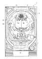
図1は、本発明の実施形態に係るパチンコ遊技機の一例を示した全体正面図である。
この図に示すパチンコ遊技機1は、矩形形状の枠2を有し、この枠2の窓孔に対して裏側から遊技盤3が着脱可能に取り付けられている。
遊技盤3の前面側には、図示しないガラス枠が開閉可能に取り付けられている。また遊技盤3の下部には遊技球を貯留する受け皿部4と、受け皿部4内の遊技球を発射する発射レバー5等が設けられている。また、受け皿部4の上部には遊技機用ボタンスイッチや、遊技球の購入ボタン、購入取り消しボタンが設けられている。
遊技盤の裏面には、液晶画面、主制御基板とサブ制御基板等、遊技の進行、演出に関わる裏部品を組み付けた合成樹脂製の機構板(何れも図示せず)が開閉自在に装着されている。遊技盤3における遊技領域3aの周囲には、発射レバー5を操作することにより発射装置から発射された遊技球を遊技領域3aの上部に案内したり、アウト口15に案内する外レールR1、及び内レールR2が設けられている。
遊技盤3のほぼ中央部には開口部6が設けられ、開口部6の内部には画像表示装置7が配置されている。画像表示装置7は、例えば、液晶表示装置等の液晶表示パネルによって構成され、通常動作状態の時は、図示しない特別図柄画像が表示される。また、いわゆる特別遊技状態の時は、特別遊技状態であることを示す演出画像等が表示される。Hereinafter, the present invention will be described in detail with reference to embodiments shown in the drawings.
FIG. 1 is an overall front view showing an example of a pachinko gaming machine according to an embodiment of the present invention.
A pachinko gaming machine 1 shown in this figure has a
A glass frame (not shown) is attached to the front side of the
On the back of the game board, a synthetic resin mechanism board (none of which is shown in the figure) is attached to the back of the game board. ing. Around the
An
開口部6の下方には、画像表示装置7の特別図柄を可変表示させるための可変入賞装置8が設けられている。
開口部6の左右両側には夫々遊技盤3の盤面上を流下する遊技球を受けるステージ部9が設けられている。ステージ部9に案内された遊技球のうち、ステージ部の所定の入口に入った遊技球は、始動入賞口11の真上に位置する出口から遊技盤面へと出て始動入賞口11に入賞し易くなり、残りの遊技球はステージ部9上から落下し、多くの場合始動入賞口11に入賞しない。
また、開口部6の左側には、遊技盤の右下部に配置された図示しない普通画像表示装置に表示される普通図柄を作動させるためのゲート13が設けられている。さらに可変入賞装置8の下方には、特別遊技状態の一つである大当たり状態のときに開成状態になる開閉扉を有する大入賞口14が設けられている。
遊技盤3には図示しない普通入賞口やアウト口15等が設けられていると共に、風車や図示しない多数の遊技釘が突設されている。遊技釘は、遊技球の落下速度を遅くすると共に、落下方向を複雑に変化させて遊技進行上の興趣を高めている。Below the
On both the left and right sides of the
Further, on the left side of the
The
普通画像表示装置に表示される普通図柄は、1個または複数個の図柄を変動表示可能であり、普通図柄始動口としてのゲート13が遊技球を検出することを条件に、その図柄が乱数制御等により所定時間可変して停止するようになっている。
普通図柄としては、数字図柄、アルファベット図柄、キャラクター図柄、その他の適宜の遊技図柄が使用される。そして、ゲート13を遊技球が通過したことを条件に乱数制御により普通図柄が所定態様となった場合に、可変入賞装置8に設けられた電動式チューリップから成る可動片を所定時間、開成動作するように構成されている。
画像表示装置7に表示される特別図柄は、停止図柄が予め定められた図柄の組合せ、例えば同一図柄の組合せとなった場合に大当たり状態となるように構成されている。また特別図柄は可変入賞装置8の始動入賞口、又は電動式チューリップの開成動作により遊技球が誘導される下始動口(図示していない)において遊技球を検出することを条件に乱数制御等により表示がスクロールする等、所定の変動パターンで所定時間変動(可変)して図柄で停止するようになっている。その際、有効ライン上に2個の停止図柄が同一となった場合に、リーチ状態が発生し、このリーチ状態において、有効ライン上の最後の停止図柄が既に停止している2個の図柄と同一となった場合に大当たり状態が発生する。なお、特別図柄としては、数字図柄、アルファベット図柄、キャラクター図柄等が使用可能である。The normal symbol displayed on the normal image display device can variably display one or a plurality of symbols, and the symbol is controlled by random numbers on the condition that the
As a normal symbol, a numerical symbol, an alphabet symbol, a character symbol, and other appropriate game symbols are used. Then, when the normal symbol becomes a predetermined mode by random number control on the condition that the game ball has passed through the
The special symbol displayed on the
図2(a)及び(b)は本発明の画像表示装置(分割型可動画像表示装置)7の閉止状態における概略構成を示す正面図、及び平面図であり、図2(c)及び(d)は開放状態における概略構成を示す正面図、及び平面図である。
本発明の特徴的な構成は、画像表示装置7を、物理的に分割状態にあり且つ夫々独立して移動可能な複数個の、本例では2個の可動表示装置7A、7Bから構成した分割型可動画像表示装置とした点にある。即ち、本発明の画像表示装置7は、遊技盤3上を異なった移動経路に沿って移動可能に支持された複数個の可動表示装置7A、7Bと、各可動表示装置7A、7Bを各移動経路に沿って進退移動させる駆動機構30(図3)と、を備え、各可動表示装置7A、7Bは、互いに近接した近接位置と、離反した離反位置との間を進退自在に構成されている点が特徴的である。
図2(a)(b)の状態においては、各可動表示装置7A、7Bは近接して内側端縁を密着させることによって、恰も大面積の一枚の表示装置である如く視認されることができ、両可動表示装置の各表示面に跨った画像Vを投影することにより遊技者は一枚の表示装置であると錯覚する。本例では、近接位置にある各可動表示装置7A、7Bの表示面は連続した平坦面となっているが、近接した端縁を離間させたり、V字状に交差させるようにしてもよい。2A and 2B are a front view and a plan view showing a schematic configuration of the image display device (split-type movable image display device) 7 according to the present invention in a closed state, and FIGS. ) Is a front view and a plan view showing a schematic configuration in an open state.
A characteristic configuration of the present invention is that the
In the state of FIGS. 2A and 2B, the
一方、図2(c)(d)の状態においては、各可動表示装置7A、7Bは観音開き状に左右(横方向)に離反して分離した状態となる。この離反状態となった各可動表示装置の表面には近接状態において2つの可動表示装置に跨って表示されていた画像Vを分割した画像V1、V2を表示し続けても良いし、新たな別個の画像を夫々表示するようにしてもよい。
各可動表示装置7A、7Bを所定の移動経路に沿って進退させるための駆動機構30の構成は種々選択可能である。
本例では、遊技盤3に形成した開口部6の奥側に凹んだ空所20を設け、この空間内に各可動表示装置7A、7Bを配置し、空所20の底面板21、及び天面板22に駆動機構30を配置する。On the other hand, in the states of FIGS. 2C and 2D, the
Various configurations of the
In this example, a recessed
駆動機構30は、図3に詳細を示す如く、底面板21、及び天面板22に夫々設けた左右対称形状のガイドスリット31、及び37、38と、各可動表示装置7A、7Bの下部及び上部に夫々設けられて各ガイドスリット31、及び37、38内に夫々遊嵌するピン33、34と、天面板22の上側に配置されたモータ等を含んだ駆動ユニット40と、を備えている。
各可動表示装置7A、7Bに設けたピン33、34は、各ガイドスリット31、及び37、38内に沿って移動する過程で各可動表示装置7A、7Bを、図2(a)(b)に示した近接位置と、(c)(d)に示した離反位置との間で安定して進退させることができる。
各可動表示装置7A、7Bと接続する信号線、電力線は、各可動表示装置7A、7Bの動作に追従し得るように構成する。As shown in detail in FIG. 3, the
The
The signal lines and power lines connected to the
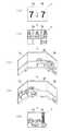
図3(a)(b)及び(c)は駆動機構を構成する駆動ユニット40の構成及び動作手順を示している。
この駆動ユニット40は、天面板22の上面に配置されており、駆動源としてのモータ41、及びモータ41の駆動力を各可動表示装置7A、7Bに伝達する伝達機構45と、を備えている。
天面板22には、各可動表示装置7A、7Bの上部に設けたピン34a、34bが夫々嵌合して移動するガイドスリット37、38が一対ずつ左右対称に配置されている。
伝達機構45は、モータ41の出力軸に固定したピニオンギヤ46と、天面板22に設けたガイドスリット22aにより進退自在に支持され且つピニオンギヤ46と噛合してピニオンギヤの回転により矢印方向へ直線的に進退する略T字形状のラックギヤ部材47と、天面板22に設けた2つの軸部48によって中間部を夫々回動自在に軸支された2つのリンク片49と、ラックギヤ部材47の一端部に設けられて各リンク片49に設けたピン49aを遊嵌させる長穴47aと、各リンク片の他端部寄りに形成されピン34aを嵌合する長穴49bと、一端を各リンク片の一端部寄りに固定されると共に他端部を天面板22の適所に固定されて各リンク片を前方へ付勢することにより各可動表示装置7A、7Bを適正な姿勢に保持するコイルバネ50と、を有している。
各リンク片49は各ピン34aを介して各可動表示装置7A、7Bの適所と連結されており、各リンク片49によって各可動表示装置7A、7Bを駆動させる。FIGS. 3A, 3B and 3C show the configuration and operation procedure of the
The driving
On the
The
Each
ピニオンギヤ46の開放方向への回転によってラックギヤ部材47が図3(a)のように奥方向へ移動すると、各リンク片49は軸部48を中心として矢印方向へ回動するため、ピン34aはガイドスリット37に沿って奥方へ移動する。このため、各可動表示装置7A、7Bは図2(c)(d)に示した離反位置に達する。逆に、ピニオンギヤ46が閉止方向へ回転すると、ラックギヤ部材47は(b)の中間状態を経て(c)の後方向へ移動し、各リンク片49は軸部48を中心として矢印方向へ回動するため、ピン34aはガイドスリット37に沿って奥方へ移動する。このため、各可動表示装置7A、7Bは図2(a)(b)に示した近接位置に達する。
なお、図示説明した駆動ユニット40の構成は一例に過ぎず、各可動表示装置7A、7Bを近接位置と離反位置との間で進退させることができる構成であればよい。
また、各可動表示装置7A、7Bを同時に動作させる必要はなく、個別に動作させるように構成してもよい。この場合の駆動機構は、各可動表示装置毎に個別に設ければよい。
また、一方の表示装置を固定とし、他方の表示装置のみを動作させるように構成しても良い。When the
The configuration of the
Further, it is not necessary to operate the
Alternatively, one display device may be fixed and only the other display device may be operated.
本発明の他の特徴は、空所20の奥部に他の表示装置(固定表示装置)60を配置し、各可動表示装置7A、7Bが図2(a)(b)に示した近接位置にあるときに各可動表示装置の背面側に他の表示装置60が隠蔽状態となり、図2(c)(d)に示した開放した離反状態(開放状態)にあるときに他の表示装置60の表示面を前面から視認できるように露出させた構成にある。
更に、他の表示装置60を前後方向、その他の方向へ進退自在に構成してもよい。
このように本実施形態では、複数に分割された可動表示装置を個別、或いは連動して動作させるばかりでなく、可動表示装置間の間隙奥部に他の表示装置60を配置したので、各可動表示装置に表示された画像と、各可動表示装置間に配置された他の表示装置上に表示された画像との協働によって多様な演出を実現することができる。
特に、可動表示装置7A、7Bと他の表示装置60とによってワイドスクリーン(ワイド画面)を構築できるため、ダイナミックな映像を表出して遊技上の雰囲気作りに貢献することができる。Another feature of the present invention is that another display device (fixed display device) 60 is disposed in the back of the
Furthermore, you may comprise the
As described above, in the present embodiment, not only the movable display devices divided into a plurality of parts are operated individually or in conjunction with each other, but the
In particular, since a wide screen (wide screen) can be constructed by the
次に、図4は本発明の他の実施形態に係る画像表示装置7の構成、及び動作を示す側部縦断面図である。
図4の実施形態に係る各可動表示装置7A、7Bは、遊技盤面に沿って上下方向へ進退自在に支持され、各可動表示装置は対向する端縁同志を近接させた近接位置と、上下方向に離反した離反位置との間を進退自在に構成されている。
各可動表示装置7A、7Bは下端部及び上端部を夫々空所20の底面板21、及び天面板22に夫々設けたヒンジ部21A、22Aによって上下方向へ回動自在に軸支されている。
或いは、図3に示した駆動機構と同様な構成の駆動機構によって、各可動表示装置を上下方向へ開閉するように構成してもよい。
更に、空所20の奥部には他の表示装置60を配置して、離反状態にある可動表示装置間に形成される間隙から露出させて前方から表示内容を視認可能に構成している。
斜めに開放した各可動表示装置7A、7Bと他の表示装置60とによりワイド画面を形成してダイナミックな映像を表出し、遊技中の雰囲気を高揚させることができる。Next, FIG. 4 is a side longitudinal sectional view showing the configuration and operation of an
Each of the
Each of the
Or you may comprise so that each movable display apparatus may be opened and closed by the drive mechanism of the structure similar to the drive mechanism shown in FIG. 3 up and down.
Further, another
The
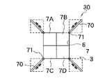
次に、図5は本発明の他の実施形態に係る画像表示装置の構成を示す正面図である。
この画像表示装置7は、密集した近接位置と、該近接位置から放射方向に離反した離反位置との間を進退自在に構成された少なくとも3個、本例では4個の可動表示装置7A〜7Dから構成されている。
各可動表示装置7A〜7Dは、密集した近接位置においては連続した大面積の画像表示装置を構成する一方で、各可動表示装置7A〜7Dが対角線方向へ退避した場合には夫々離反した位置関係となる。
各可動表示装置を個別に動作させてもよい。
各可動表示装置7A〜7Dを進退させるための駆動機構としては、遊技盤等に設けた各スリット70内に各可動表示装置に設けたピン71を嵌合させることによって各可動表示装置を対角線方向(放射方向)へ進退自在に構成するとともに、モータによって各可動表示装置を駆動する。モータからの駆動力は図示しないギヤ、ワイヤ等を用いて各可動表示装置に伝達する。
この画像表示装置7の背面側、即ち各可動表示装置7A〜7Dの背面側(空所20の奥部)に、図示しない他の表示装置(固定表示装置)を配置し、各可動表示装置が離反位置にあるときに他の表示装置が前方から視認可能となるように構成する。
Next, FIG. 5 is a front view showing a configuration of an image display apparatus according to another embodiment of the present invention.
The
Each of the
Each movable display device may be operated individually.
As a drive mechanism for advancing and retracting each
Another display device (fixed display device) (not shown) is arranged on the back side of the
次に、本実施形態の画像表示装置を利用した遊技演出例について説明する。なお、本実施形態では2個の表示装置7A、7Bから構成した分割型の画像表示装置7を例に挙げて説明する。
図6は、本実施形態の画像表示装置を利用して図柄変動の演出を行った場合の表示態様の一例を示した図である。
画像表示装置7を利用して図柄変動の演出を行う場合は、画像表示装置7の各可動表示装置7A、7Bを近接位置に配置して一体化した状態で、図6(a)に示すように、画像表示装置7に3つの図柄を表示する。そして、図6(b)に示すように、3つの図柄のうち2つの図柄が揃ってリーチが発生すると、近接位置に配置されていた可動表示装置7A、7Bを左右方向に離反して、図6(c)に示すように、左側の可動表示装置7Aに左図柄、右側の可動表示装置7Bに右図柄をそれぞれ表示し、可動表示装置7A、7Bが一体化した状態のときは背面側に隠蔽状態にあった固定表示装置60に最後に停止する中図柄を表示して図柄演出を行う。Next, a game effect example using the image display device of the present embodiment will be described. In the present embodiment, a description will be given by taking as an example a split-type
FIG. 6 is a diagram showing an example of a display mode when the effect of symbol variation is performed using the image display device of the present embodiment.
When the effect of symbol variation is performed using the
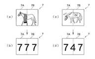
図7は、本実施形態の画像表示装置を利用してリーチ演出を行った場合の表示態様の一例を示した図である。
画像表示装置7を利用してリーチ演出を行う場合は、画像表示装置7の各可動表示装置7A、7Bを近接位置に配置して一体化した状態で、画像表示装置7に3つの図柄を表示する。そして、図7(a)に示すように、3つの図柄のうち2つの図柄が揃ってリーチが発生すると、画像表示装置7の画像が図7(b)に示すような画像、例えばスタートゲートの画像とを表示する。この後、スタートゲートが空いて馬がゲートから飛び出すタイミングで以って、可動表示装置7A、7Bを左右方向に離反して、図7(c)に示すように、各可動表示装置7A、7Bの背面側に隠蔽状態にあった固定表示装置60を露出して、これら3つの表示装置を用いて競馬場全体を写すような画像を表示すると共に、馬が右側の可動表示装置7Bから左側の可動表示装置7Aに向かって走るような画像表示を行う。
そして、図7(d)に示すように、馬が左側の可動表示装置7Aの左端に達したタイミングで以って、図7(e)に示すように画像表示装置7の各可動表示装置7A、7Bを一体化して、ゴール前の最後の直線画像を表示した後、画像表示装置7に大当たり結果を表示する。例えば、大当たりに当選している場合は、図8(a)に示すような「勝利」を表す演出画像を表示した後、図8(b)に示すような大当たり図柄画像の表示を行う。一方、大当たりに当選していない場合は、図8(c)に示すような「敗北」を表す演出画像を表示した後、図8(d)に示すようなハズレ図柄画像の表示を行う。FIG. 7 is a diagram illustrating an example of a display mode when a reach effect is performed using the image display device of the present embodiment.
When the reach display is performed using the
Then, as shown in FIG. 7D, at the timing when the horse reaches the left end of the left
以上のように本発明では、複数個の表示装置を、遊技盤上を異なった移動経路に沿って移動させるように構成したので、遊技内容に意外性を発揮させたり、角度、姿勢を異ならせた表示装置を利用して立体的な映像を作出することができる。
特に、本発明では、複数の表示装置の位置関係を異ならせることができるので、従来のように平面的な同一表示面上において画像データを種々操作する場合とは異なり、立体感と、多様性と意外性を有した演出を実現することができ、更に制御プログラム等の装置構成を簡略化してコストダウンを図ることができる。
また、近接位置においては一枚の表示装置としか見えないにも拘わらず、遊技の進行中に表示装置が複数に分割し、しかも各可動表示装置上の表示内容を工夫することにより、バリエーションに富んだ遊技内容を演出することが可能となる。
更に、複数に分割された表示装置を個別、或いは連動して動作させるばかりでなく、表示装置間の間隙奥部に他の表示装置を配置し、可動表示装置の離反時に他の表示装置が遊技盤前方から視認できるようにしたので、各可動表示装置に表示された画像と、可動表示装置間に配置された他の表示装置にとの協働によって多様な演出を実現することができる。
なお、本発明の分割型可動画像表示装置に用いる表示装置としては、液晶表示装置、リアプロジェクタ、その他、任意の表示装置を採用することができる。
本発明の分割型可動画像表示装置、或いは本発明の分割型可動画像表示装置を備えた遊技盤は、パチンコ遊技機のみならず、スロットマシン、その他、表示装置を有した遊技機、ゲーム機一般に適用することができる。As described above, according to the present invention, the plurality of display devices are configured to move on the game board along different movement paths, so that the game content can be displayed unexpectedly, or can have different angles and postures. 3D images can be created using the display device.
In particular, according to the present invention, since the positional relationship of a plurality of display devices can be made different, unlike the case where various operations are performed on image data on the same flat display surface as in the prior art, the stereoscopic effect and the diversity It is possible to realize an effect with unexpectedness and to simplify the apparatus configuration such as a control program and reduce the cost.
In addition, the display device is divided into a plurality of parts while the game is in progress, even though it can only be seen as a single display device at the close position, and the display contents on each movable display device are devised to make variations. It is possible to produce rich game content.
Furthermore, not only the display devices divided into a plurality of units are operated individually or in conjunction with each other, but another display device is arranged in the back of the gap between the display devices, and the other display device plays a game when the movable display device is separated. Since it can be viewed from the front of the panel, various effects can be realized by cooperation between the image displayed on each movable display device and another display device arranged between the movable display devices.
As the display device used in the split movable image display device of the present invention, a liquid crystal display device, a rear projector, and other arbitrary display devices can be employed.
The split-type movable image display device of the present invention or a game board equipped with the split-type movable image display device of the present invention is not limited to pachinko gaming machines, slot machines, other gaming machines having display devices, and game machines in general. Can be applied.
1…パチンコ遊技機、3…遊技盤、3a…遊技領域、4…皿部、5…発射レバー、6…開口部、7…画像可動表示装置、7A、7B…表示装置、8…可変入賞装置、9…ステージ部、11…始動入賞口、13…ゲート、14…大入賞口、15…アウト口、20…空所、21…底面板、21A、22A…ヒンジ部、22…天面板、22a…ガイドスリット、30…駆動機構、31…ガイドスリット、33…ピン、34a、34b…ピン、37…ガイドスリット、40…駆動ユニット、41…モータ、45…伝達機構、46…ピニオンギヤ、47…ラックギヤ部材、47a…長穴、48…軸部、49…リンク片、49a…ピン、49b…長穴、50…コイルバネ、60…他の表示装置、70…スリット、71…ピン DESCRIPTION OF SYMBOLS 1 ... Pachinko machine, 3 ... Game board, 3a ... Game area, 4 ... Dish part, 5 ... Launch lever, 6 ... Opening part, 7 ... Image movable display apparatus, 7A, 7B ... Display apparatus, 8 ... Variable prize-winning apparatus , 9 ... Stage section, 11 ... Start winning opening, 13 ... Gate, 14 ... Large winning opening, 15 ... Out opening, 20 ... Empty space, 21 ... Bottom plate, 21A, 22A ... Hinge portion, 22 ... Top plate, 22a Guide slit, 30 ... Drive mechanism, 31 ... Guide slit, 33 ... Pin, 34a, 34b ... Pin, 37 ... Guide slit, 40 ... Drive unit, 41 ... Motor, 45 ... Transmission mechanism, 46 ... Pinion gear, 47 ... Rack gear Member, 47a ... Long hole, 48 ... Shaft, 49 ... Link piece, 49a ... Pin, 49b ... Long hole, 50 ... Coil spring, 60 ... Other display device, 70 ... Slit, 71 ... Pin
Claims (7)
Translated fromJapanese前記各可動表示装置は、互いに近接した近接位置と、離反した離反位置との間を進退自在に構成されており、
前記各可動表示装置が近接位置にあるときにはその背面側に隠蔽され、離反位置にあるときには露出される他の表示装置を備えたことを特徴とする分割型可動画像表示装置。A plurality of display devices supported so as to be movable along different movement paths in the vicinity of the game board, and a drive mechanism for moving the respective movable display devices forward and backward along the respective movement paths,
Each of the movable display devices is configured to be able to advance and retreat between a proximity position close to each other and a separation position separated from each other.
A split-type movable image display device comprising: another display device that is hidden behind the movable display device when the movable display device is in the proximity position and exposed when the movable display device is in the separation position.
Priority Applications (1)
| Application Number | Priority Date | Filing Date | Title |
|---|---|---|---|
| JP2008193630AJP2010029372A (en) | 2008-07-28 | 2008-07-28 | Division type movable image display, game board and pachinko game machine |
Applications Claiming Priority (1)
| Application Number | Priority Date | Filing Date | Title |
|---|---|---|---|
| JP2008193630AJP2010029372A (en) | 2008-07-28 | 2008-07-28 | Division type movable image display, game board and pachinko game machine |
Publications (1)
| Publication Number | Publication Date |
|---|---|
| JP2010029372Atrue JP2010029372A (en) | 2010-02-12 |
Family
ID=41734581
Family Applications (1)
| Application Number | Title | Priority Date | Filing Date |
|---|---|---|---|
| JP2008193630APendingJP2010029372A (en) | 2008-07-28 | 2008-07-28 | Division type movable image display, game board and pachinko game machine |
Country Status (1)
| Country | Link |
|---|---|
| JP (1) | JP2010029372A (en) |
Cited By (18)
| Publication number | Priority date | Publication date | Assignee | Title |
|---|---|---|---|---|
| JP2012075465A (en)* | 2010-09-30 | 2012-04-19 | Kyoraku Sangyo Kk | Movable performance device and pachinko game machine with the same |
| JP2012075469A (en)* | 2010-09-30 | 2012-04-19 | Kyoraku Sangyo Kk | Movable performance device and pachinko game machine with the same |
| JP2013017668A (en)* | 2011-07-12 | 2013-01-31 | Fujishoji Co Ltd | Game machine |
| JP2015080649A (en)* | 2013-10-23 | 2015-04-27 | 株式会社三共 | Game machine |
| JP2015080648A (en)* | 2013-10-23 | 2015-04-27 | 株式会社三共 | Game machine |
| JP2015080651A (en)* | 2013-10-23 | 2015-04-27 | 株式会社三共 | Game machine |
| JP2015080650A (en)* | 2013-10-23 | 2015-04-27 | 株式会社三共 | Game machine |
| JP2015112176A (en)* | 2013-12-10 | 2015-06-22 | 株式会社三共 | Game machine |
| JP2015126878A (en)* | 2013-11-29 | 2015-07-09 | 株式会社三共 | Game board |
| JP2015173854A (en)* | 2014-03-17 | 2015-10-05 | 株式会社大一商会 | Game machine |
| JP2015188460A (en)* | 2014-03-27 | 2015-11-02 | 株式会社大一商会 | Game machine |
| JP2015188459A (en)* | 2014-03-27 | 2015-11-02 | 株式会社大一商会 | Game machine |
| JP2015188457A (en)* | 2014-03-27 | 2015-11-02 | 株式会社大一商会 | Game machine |
| JP2015228874A (en)* | 2014-06-03 | 2015-12-21 | 株式会社大一商会 | Game machine |
| JP2015228875A (en)* | 2014-06-03 | 2015-12-21 | 株式会社大一商会 | Game machine |
| JP2016104282A (en)* | 2016-03-01 | 2016-06-09 | 株式会社サンセイアールアンドディ | Game machine |
| JP2016135308A (en)* | 2016-03-25 | 2016-07-28 | 京楽産業.株式会社 | Game machine |
| JP2018020191A (en)* | 2017-10-06 | 2018-02-08 | 株式会社ユニバーサルエンターテインメント | Game machine |
Citations (3)
| Publication number | Priority date | Publication date | Assignee | Title |
|---|---|---|---|---|
| JPH0919552A (en)* | 1995-07-05 | 1997-01-21 | Maruhon Ind Co Ltd | Pachinko machine |
| JP2006304848A (en)* | 2005-04-26 | 2006-11-09 | Sansei R & D:Kk | Game machine |
| JP2007185256A (en)* | 2006-01-11 | 2007-07-26 | Samii Kk | Game machine |
- 2008
- 2008-07-28JPJP2008193630Apatent/JP2010029372A/enactivePending
Patent Citations (3)
| Publication number | Priority date | Publication date | Assignee | Title |
|---|---|---|---|---|
| JPH0919552A (en)* | 1995-07-05 | 1997-01-21 | Maruhon Ind Co Ltd | Pachinko machine |
| JP2006304848A (en)* | 2005-04-26 | 2006-11-09 | Sansei R & D:Kk | Game machine |
| JP2007185256A (en)* | 2006-01-11 | 2007-07-26 | Samii Kk | Game machine |
Cited By (18)
| Publication number | Priority date | Publication date | Assignee | Title |
|---|---|---|---|---|
| JP2012075465A (en)* | 2010-09-30 | 2012-04-19 | Kyoraku Sangyo Kk | Movable performance device and pachinko game machine with the same |
| JP2012075469A (en)* | 2010-09-30 | 2012-04-19 | Kyoraku Sangyo Kk | Movable performance device and pachinko game machine with the same |
| JP2013017668A (en)* | 2011-07-12 | 2013-01-31 | Fujishoji Co Ltd | Game machine |
| JP2015080649A (en)* | 2013-10-23 | 2015-04-27 | 株式会社三共 | Game machine |
| JP2015080648A (en)* | 2013-10-23 | 2015-04-27 | 株式会社三共 | Game machine |
| JP2015080651A (en)* | 2013-10-23 | 2015-04-27 | 株式会社三共 | Game machine |
| JP2015080650A (en)* | 2013-10-23 | 2015-04-27 | 株式会社三共 | Game machine |
| JP2015126878A (en)* | 2013-11-29 | 2015-07-09 | 株式会社三共 | Game board |
| JP2015112176A (en)* | 2013-12-10 | 2015-06-22 | 株式会社三共 | Game machine |
| JP2015173854A (en)* | 2014-03-17 | 2015-10-05 | 株式会社大一商会 | Game machine |
| JP2015188460A (en)* | 2014-03-27 | 2015-11-02 | 株式会社大一商会 | Game machine |
| JP2015188459A (en)* | 2014-03-27 | 2015-11-02 | 株式会社大一商会 | Game machine |
| JP2015188457A (en)* | 2014-03-27 | 2015-11-02 | 株式会社大一商会 | Game machine |
| JP2015228874A (en)* | 2014-06-03 | 2015-12-21 | 株式会社大一商会 | Game machine |
| JP2015228875A (en)* | 2014-06-03 | 2015-12-21 | 株式会社大一商会 | Game machine |
| JP2016104282A (en)* | 2016-03-01 | 2016-06-09 | 株式会社サンセイアールアンドディ | Game machine |
| JP2016135308A (en)* | 2016-03-25 | 2016-07-28 | 京楽産業.株式会社 | Game machine |
| JP2018020191A (en)* | 2017-10-06 | 2018-02-08 | 株式会社ユニバーサルエンターテインメント | Game machine |
Similar Documents
| Publication | Publication Date | Title |
|---|---|---|
| JP2010029372A (en) | Division type movable image display, game board and pachinko game machine | |
| JP2010029470A (en) | Division type movable image display, game board and game machine | |
| JP4853783B2 (en) | Game machine | |
| JP4931882B2 (en) | Decorative body unit | |
| JP2010029471A (en) | Image display, game board and game machine | |
| JP5756612B2 (en) | Game machine | |
| JP5271623B2 (en) | Decorative body unit | |
| JP2009125300A (en) | Game machine | |
| JP4350053B2 (en) | Display device for gaming machine | |
| JP5640267B1 (en) | Game machine | |
| JP2009195371A (en) | Image display apparatus and game machine | |
| JP2014076208A (en) | Movable accessory device | |
| JP2011183051A (en) | Pachinko machine | |
| JP2010029373A (en) | Movable image display, game board and pachinko game machine | |
| JP6086847B2 (en) | Game machine | |
| JP5890640B2 (en) | Game machine | |
| JP2010029371A (en) | Division type movable image display, game board and game machine | |
| JP5757046B1 (en) | Game machine | |
| JP5750184B1 (en) | Game machine | |
| JP5390353B2 (en) | Movable panel parts, game board units, and pachinko machines | |
| JP2011015736A (en) | Movable board surface component, game board unit, and pachinko game machine | |
| JP2017006164A (en) | Game machine | |
| JP2009077885A (en) | Slot machine | |
| JP4185504B2 (en) | Pusher type game machine | |
| JP5669159B1 (en) | Game machine |
Legal Events
| Date | Code | Title | Description |
|---|---|---|---|
| A621 | Written request for application examination | Effective date:20110520 Free format text:JAPANESE INTERMEDIATE CODE: A621 | |
| A131 | Notification of reasons for refusal | Effective date:20120626 Free format text:JAPANESE INTERMEDIATE CODE: A131 | |
| A02 | Decision of refusal | Effective date:20121106 Free format text:JAPANESE INTERMEDIATE CODE: A02 |