JP2010022128A - Charge/discharge control system for electric storage device - Google Patents
Charge/discharge control system for electric storage deviceDownload PDFInfo
- Publication number
- JP2010022128A JP2010022128AJP2008180049AJP2008180049AJP2010022128AJP 2010022128 AJP2010022128 AJP 2010022128AJP 2008180049 AJP2008180049 AJP 2008180049AJP 2008180049 AJP2008180049 AJP 2008180049AJP 2010022128 AJP2010022128 AJP 2010022128A
- Authority
- JP
- Japan
- Prior art keywords
- power storage
- charge
- storage device
- discharge
- soc
- Prior art date
- Legal status (The legal status is an assumption and is not a legal conclusion. Google has not performed a legal analysis and makes no representation as to the accuracy of the status listed.)
- Pending
Links
Images


Classifications
- Y—GENERAL TAGGING OF NEW TECHNOLOGICAL DEVELOPMENTS; GENERAL TAGGING OF CROSS-SECTIONAL TECHNOLOGIES SPANNING OVER SEVERAL SECTIONS OF THE IPC; TECHNICAL SUBJECTS COVERED BY FORMER USPC CROSS-REFERENCE ART COLLECTIONS [XRACs] AND DIGESTS
- Y02—TECHNOLOGIES OR APPLICATIONS FOR MITIGATION OR ADAPTATION AGAINST CLIMATE CHANGE
- Y02E—REDUCTION OF GREENHOUSE GAS [GHG] EMISSIONS, RELATED TO ENERGY GENERATION, TRANSMISSION OR DISTRIBUTION
- Y02E60/00—Enabling technologies; Technologies with a potential or indirect contribution to GHG emissions mitigation
- Y02E60/10—Energy storage using batteries
- Y—GENERAL TAGGING OF NEW TECHNOLOGICAL DEVELOPMENTS; GENERAL TAGGING OF CROSS-SECTIONAL TECHNOLOGIES SPANNING OVER SEVERAL SECTIONS OF THE IPC; TECHNICAL SUBJECTS COVERED BY FORMER USPC CROSS-REFERENCE ART COLLECTIONS [XRACs] AND DIGESTS
- Y02—TECHNOLOGIES OR APPLICATIONS FOR MITIGATION OR ADAPTATION AGAINST CLIMATE CHANGE
- Y02T—CLIMATE CHANGE MITIGATION TECHNOLOGIES RELATED TO TRANSPORTATION
- Y02T10/00—Road transport of goods or passengers
- Y02T10/60—Other road transportation technologies with climate change mitigation effect
- Y02T10/62—Hybrid vehicles
- Y—GENERAL TAGGING OF NEW TECHNOLOGICAL DEVELOPMENTS; GENERAL TAGGING OF CROSS-SECTIONAL TECHNOLOGIES SPANNING OVER SEVERAL SECTIONS OF THE IPC; TECHNICAL SUBJECTS COVERED BY FORMER USPC CROSS-REFERENCE ART COLLECTIONS [XRACs] AND DIGESTS
- Y02—TECHNOLOGIES OR APPLICATIONS FOR MITIGATION OR ADAPTATION AGAINST CLIMATE CHANGE
- Y02T—CLIMATE CHANGE MITIGATION TECHNOLOGIES RELATED TO TRANSPORTATION
- Y02T10/00—Road transport of goods or passengers
- Y02T10/60—Other road transportation technologies with climate change mitigation effect
- Y02T10/7072—Electromobility specific charging systems or methods for batteries, ultracapacitors, supercapacitors or double-layer capacitors
Landscapes
- Electric Propulsion And Braking For Vehicles (AREA)
- Hybrid Electric Vehicles (AREA)
- Charge And Discharge Circuits For Batteries Or The Like (AREA)
- Secondary Cells (AREA)
Abstract
Translated fromJapaneseDescription
Translated fromJapanese本発明は、蓄電装置充放電制御システムに係り、特に複数の蓄電装置を有する電源における蓄電装置充放電制御システムに関する。 The present invention relates to a power storage device charge / discharge control system, and more particularly to a power storage device charge / discharge control system in a power source having a plurality of power storage devices.
例えば、車両の駆動源として回転電機を用いるときは、その回転電機に電力を供給するために2次電池等の蓄電装置が用いられる。この蓄電装置を充電するには、エンジンで回転電機を発電機として用いて駆動し、その発電電力を利用することができる。このように、モータと発電機の機能を有する回転電機とエンジンと蓄電装置とを用いて走行を行う車両は、ハイブリッド車両と呼ばれることがある。 For example, when a rotating electrical machine is used as a drive source for a vehicle, a power storage device such as a secondary battery is used to supply power to the rotating electrical machine. In order to charge this power storage device, the engine can be driven using a rotating electrical machine as a generator, and the generated power can be used. Thus, a vehicle that travels using a rotating electrical machine having the functions of a motor and a generator, an engine, and a power storage device may be called a hybrid vehicle.
例えば、特許文献1には、自動車の制御方法として、目的地まで走行する際にエンジンの運転が必要な走行必要運転時間を推定すると共に、車両が目的地に到達するまでにバッテリの残容量を所定範囲で保持するためにエンジンの運転が必要な充電必要運転時間を推定することが述べられている。そして、前者が大きいときは、エンジン・モータ運転モードで走行している最中にバッテリの充電を十分に行うことができるとして、始動要求時に、エンジンを始動せず、これによって、車両の停車中に予期しないエンジンの始動によって運転者に違和感を与えることを抑制できる、と述べられている。 For example, in Patent Document 1, as a method for controlling an automobile, a travel time required for driving an engine when traveling to a destination is estimated, and the remaining capacity of the battery is determined until the vehicle reaches the destination. It is stated that the required operation time required for charging the engine to be operated in order to maintain it within a predetermined range is estimated. When the former is large, the battery can be sufficiently charged while traveling in the engine / motor operation mode, and the engine is not started at the time of the start request. It is stated that the driver can be prevented from feeling uncomfortable due to unexpected engine start.
このように、蓄電装置と回転電機とを接続して用いる場合に、複数の蓄電装置を組み合わせて全体として1つの電源を構成することで、電源としての容量が増加し、また電源の利用について自由度が大きくなる。この場合には、個々の蓄電装置が必ずしも完全に同じように充電または放電を行うわけではないので、それぞれの蓄電装置の充電状態が異なってくることが生じる。蓄電装置は、充電しすぎても放電しすぎても蓄電性能が低下することが知られているので、個々の蓄電装置の充電状態の管理が必要で、そのために蓄電装置の充放電制御が行われる。 As described above, when the power storage device and the rotating electrical machine are connected and used, a plurality of power storage devices are combined to form one power source as a whole, thereby increasing the capacity as a power source and free use of the power source. The degree is increased. In this case, since the individual power storage devices do not always perform charging or discharging in exactly the same way, the charge states of the respective power storage devices may differ. It is known that the power storage performance of a power storage device deteriorates if it is overcharged or discharged too much. Therefore, it is necessary to manage the charge state of each power storage device. Is called.
例えば、特許文献1には、電動モータ電源管理システムとして、2つのモータと2つのインバータとともに、それぞれが電池とブースト/バック直流・交流コンバータを有し、並列に配線されインバータに直流電源を提供する3つの電源ステージを備える構成が開示されている。ここでは、この3つの電源ステージが同じSOCとなるように、それぞれがIadjと検出電流とを比較し、エラーをゼロにすることで、各電池が均等に充電されるように制御される。ここでSOC(State Of Charge)は電池の総容量に対する放電可能な電流の比率として述べられる充電状態値である。 For example, in Patent Document 1, as an electric motor power management system, two motors and two inverters, each having a battery and a boost / buck DC / AC converter, are wired in parallel and provide DC power to the inverter. A configuration including three power supply stages is disclosed. Here, each battery is controlled to be charged uniformly by comparing Iadj and the detected current and setting the error to zero so that the three power supply stages have the same SOC. Here, SOC (State Of Charge) is a state of charge value described as a ratio of a dischargeable current to a total capacity of the battery.
特許文献2の技術では、3つの電池がそれぞれ同じSOCとなるように制御が行われるが、そのためには、それぞれの電池における検出電流とIadjとを比較し、エラーをゼロにするという面倒な制御を行う必要がある。この様な複雑な制御を用いない簡単な充放電制御の1つとして、平均SOCを用いる方法がある。この方法は、複数の蓄電装置について、それぞれのSOCの平均値を求め、その平均SOCに対して予め定めた充電限界値と放電限界値との間に入るように、複数の蓄電装置を1つの電源装置と考えて全体としての充放電制御を行うものである。 In the technology of Patent Document 2, control is performed so that the three batteries have the same SOC, but for that purpose, the detected current in each battery is compared with Iadj, and the troublesome control of making the error zero. Need to do. One simple charge / discharge control that does not use such complicated control is a method that uses an average SOC. In this method, for each of a plurality of power storage devices, an average value of each SOC is obtained, and a plurality of power storage devices are connected to one average so as to fall between a predetermined charge limit value and a discharge limit value with respect to the average SOC. As a power supply device, charge / discharge control as a whole is performed.
このように平均SOCを用いることで蓄電装置の充放電制御が簡明なものとなる。ところで、複数の蓄電装置の中で、SOCにかなり差がある場合に問題が生じえる。すなわち、平均SOCが充電限界値と放電限界値との間に入っていても、個々の蓄電装置の中には充電限界値または放電限界値を超えるものがあることがある。上記のように蓄電装置は過充電となっても過放電となっても性能が低下するので、このままでは問題が生じる。 In this way, charge / discharge control of the power storage device is simplified by using the average SOC. By the way, a problem may arise when there is a considerable difference in SOC among a plurality of power storage devices. That is, even if the average SOC is between the charge limit value and the discharge limit value, some individual power storage devices may exceed the charge limit value or the discharge limit value. As described above, since the performance of the power storage device deteriorates even when it is overcharged or overdischarged, a problem arises as it is.
本発明の目的は、複数の蓄電装置を用いる場合に、それぞれの蓄電装置の過充電、過放電を抑制することができる蓄電装置充放電制御システムを提供することである。 An object of the present invention is to provide a power storage device charge / discharge control system capable of suppressing overcharge and overdischarge of each power storage device when a plurality of power storage devices are used.
本発明に係る蓄電装置充放電制御システムは、全体として充放電制御が行われる複数の蓄電装置と、各蓄電装置の充電状態値を取得する手段と、各蓄電装置の充電状態値を予め定めた充電限界値および予め定めた放電限界値と比較する手段と、いずれか1つの蓄電装置の充電状態値が充電限界値を超えるときに、複数の蓄電装置の全体に対し強制的に放電を行い、または、いずれか1つの蓄電装置の充電状態値が放電限界値を超えるときに、複数の蓄電装置の全体に対し強制的に充電を行う強制充放電手段と、を備えることを特徴とする。 A power storage device charge / discharge control system according to the present invention has a plurality of power storage devices for which charge / discharge control is performed as a whole, a means for obtaining a charge state value of each power storage device, and a charge state value for each power storage device. Means for comparing the charge limit value and a predetermined discharge limit value, and when the charge state value of any one power storage device exceeds the charge limit value, forcibly discharging the whole of the plurality of power storage devices; Alternatively, forcibly charging / discharging means for forcibly charging the entirety of the plurality of power storage devices when the charge state value of any one power storage device exceeds a discharge limit value is provided.
また、本発明に係る蓄電装置充放電制御システムにおいて、いずれか1つの蓄電装置の充電状態値が充電限界値を超えたための強制放電によって充電状態値が低下し、各蓄電装置の充電状態値のすべてが予め定めた強制放電解除値以下となるときに強制放電を止めて通常の充放電制御に戻し、または、いずれか1つの蓄電装置の充電状態値が放電限界値を超えたための強制充電によって充電状態値が上昇し、各蓄電装置の充電状態値のすべてが予め定めた充電解除値以上となるときに強制充電を止めて通常の充放電制御に戻す強制充放電解除手段を備えるが好ましい。 Further, in the power storage device charge / discharge control system according to the present invention, the charge state value decreases due to forced discharge because the charge state value of any one of the power storage devices exceeds the charge limit value, and the charge state value of each power storage device When all are below a predetermined forced discharge release value, the forced discharge is stopped and returned to normal charge / discharge control, or by the forced charge because the charge state value of any one power storage device exceeds the discharge limit value It is preferable to provide forcible charge / discharge release means for stopping the forced charge and returning to normal charge / discharge control when the charge state value rises and all of the charge state values of the respective power storage devices are equal to or higher than a predetermined charge release value.
また、本発明に係る蓄電装置充放電制御システムは、全体として充放電制御が行われる複数の蓄電装置と、各蓄電装置の充電状態値を取得する手段と、各蓄電装置の充電状態値を予め定めた充電限界値および予め定めた放電限界値と比較する手段と、各蓄電装置の充電状態値がすべて充電限界値または放電限界値を超えるときに、複数の蓄電装置の全体に対し放電または充電を行う充放電手段と、少なくとも1つの蓄電装置の充電状態値が充電限界値を超えていない一方で、充電限界値を超えているいずれか1つの蓄電装置がさらに予め定めた保護上限値を超えるときに、複数の蓄電装置の全体に対し強制的な保護放電を行い、または、少なくとも1つの蓄電装置の充電状態値が放電限界値を超えていない一方で、放電限界値を超えているいずれか1つの蓄電装置がさらに予め定めた保護下限値を超えるときに、複数の蓄電装置の全体に対し強制的な保護充電を行う強制保護充放電手段を備えることを特徴とする。 The power storage device charge / discharge control system according to the present invention includes a plurality of power storage devices for which charge / discharge control is performed as a whole, means for acquiring a charge state value of each power storage device, and a charge state value of each power storage device in advance. A means for comparing with a predetermined charging limit value and a predetermined discharging limit value, and when all of the charging state values of each power storage device exceed a charging limit value or a discharging limit value, discharging or charging the whole of a plurality of power storage devices And the charge state of the at least one power storage device does not exceed the charge limit value, but any one power storage device exceeding the charge limit value further exceeds a predetermined protection upper limit value Sometimes, a forcible protective discharge is performed on the whole of the plurality of power storage devices, or the charge state value of at least one power storage device does not exceed the discharge limit value but exceeds the discharge limit value. Re or when one of the power storage device exceeds a further predetermined protection lower limit, characterized in that it comprises a forced protection discharge means for performing a forced protection charge for the whole of the plurality of power storage devices.
また、本発明に係る蓄電装置充放電制御システムにおいて、いずれか1つの蓄電装置の充電状態値が保護上限値を超えたために強制保護放電を行い、それによって充電状態値が低下し、各蓄電装置の充電状態値のすべてが予め定めた保護放電解除値以下となるときに強制保護放電を止めて通常の充放電制御に戻し、または、いずれか1つの蓄電装置の充電状態値が保護下限界値を超えたために強制保護充電を行い、それによって充電状態値が上昇し、各蓄電装置の充電状態値のすべてが予め定めた保護充電解除値以上となるときに強制保護充電を止めて通常の充放電制御に戻す強制保護充放電解除手段を備えることが好ましい。 Further, in the power storage device charge / discharge control system according to the present invention, since the charge state value of any one of the power storage devices exceeds the protection upper limit value, the forced protection discharge is performed, thereby reducing the charge state value, and each power storage device When all of the charge state values of the battery are equal to or less than a predetermined protection discharge release value, the forced protection discharge is stopped and the normal charge / discharge control is resumed, or the charge state value of any one of the power storage devices is the lower limit value of protection Forcibly protected charging is performed and the charge state value increases, and when all of the charge state values of each power storage device are equal to or greater than the predetermined protection charge release value, the forced protection charge is stopped and normal charge is performed. It is preferable to provide a forced protection charge / discharge release means for returning to the discharge control.
また、本発明に係る蓄電装置充放電制御システムにおいて、保護放電解除値は、充電限界値よりも低い値に設定され、保護充電解除値は、放電限界値よりも高い値に設定されることが好ましい。 Further, in the power storage device charge / discharge control system according to the present invention, the protection discharge release value may be set to a value lower than the charge limit value, and the protection charge release value may be set to a value higher than the discharge limit value. preferable.
上記構成の少なくとも1つにより、蓄電装置充放電制御システムは、いずれか1つの蓄電装置の充電状態値が予め定めた充電限界値を超えるときに、複数の蓄電装置の全体に対し強制的に放電を行い、または、いずれか1つの蓄電装置の充電状態値が予め定めた放電限界値を超えるときに、複数の蓄電装置の全体に対し強制的に充電を行う。充電状態値をSOCとして示すものとすると、複数の蓄電装置について平均のSOCが充電限界値と放電限界値の中に入っているが、個々の蓄電装置の中にはそのSOCが充電限界値を超え、あるいは放電限界値が超えるものがある場合に、強制的に全体に対し放電あるいは充電を行う。これによって、個々の蓄電装置の過充電、過放電を抑制することができる。 With at least one of the above-described configurations, the power storage device charge / discharge control system forcibly discharges all of the plurality of power storage devices when the charge state value of any one power storage device exceeds a predetermined charge limit value. Or when the charge state value of any one of the power storage devices exceeds a predetermined discharge limit value, the whole of the plurality of power storage devices is forcibly charged. Assuming that the state of charge value is indicated as SOC, the average SOC of a plurality of power storage devices is included in the charge limit value and the discharge limit value. If there is something that exceeds or exceeds the discharge limit value, the whole is forcibly discharged or charged. Thereby, overcharge and overdischarge of each power storage device can be suppressed.
また、蓄電装置充放電制御システムにおいて、強制放電によって各蓄電装置の充電状態値のすべてが予め定めた強制放電解除値以下となるときに強制放電を止めて通常の充放電制御に戻し、または強制充電によって各蓄電装置の充電状態値のすべてが予め定めた充電解除値以上となるときに強制充電を止めて通常の充放電制御に戻す。これによって、強制的な充放電制御をできるだけ短時間にとどめることができる。 Further, in the power storage device charge / discharge control system, when all of the charge state values of each power storage device are equal to or less than a predetermined forced discharge release value by forced discharge, the forced discharge is stopped and returned to normal charge / discharge control, or forced When all the charge state values of the respective power storage devices become equal to or higher than a predetermined charge release value due to charging, the forced charging is stopped and the normal charge / discharge control is returned to. As a result, forced charge / discharge control can be kept as short as possible.
また、蓄電装置充放電制御システムは、各蓄電装置の充電状態値がすべて充電限界値または放電限界値を超えるときに、複数の蓄電装置の全体に対し放電または充電を行うものとし、少なくとも1つの蓄電装置の充電状態値が充電限界値を超えていない一方で、充電限界値を超えているいずれか1つの蓄電装置がさらに予め定めた保護上限値を超えるときに、複数の蓄電装置の全体に対し強制的な保護放電を行い、または、少なくとも1つの蓄電装置の充電状態値が放電限界値を超えていない一方で、放電限界値を超えているいずれか1つの蓄電装置がさらに予め定めた保護下限値を超えるときに、複数の蓄電装置の全体に対し強制的な保護充電を行う。 Further, the power storage device charge / discharge control system discharges or charges the whole of the plurality of power storage devices when all of the charge state values of the power storage devices exceed the charge limit value or the discharge limit value, and at least one When any one power storage device exceeding the charge limit value exceeds the predetermined protection upper limit value while the charge state value of the power storage device does not exceed the charge limit value, A forcible protective discharge is performed, or the charge state value of at least one power storage device does not exceed the discharge limit value, but any one power storage device that exceeds the discharge limit value is further protected in advance. When the lower limit value is exceeded, forcible protective charging is performed on the whole of the plurality of power storage devices.
ここで、少なくとも1つの蓄電装置のSOCが充電限界値と放電限界値の間に入っているときは、蓄電装置の電力を用いて回転電機を駆動することができる。このようなときに、蓄電装置の充放電制御を行うと、回転電機の駆動期間が短くなる。上記構成によれば、少なくとも1つの蓄電装置のSOCが充電限界値を超え、あるいは放電限界値を超えるので、通常であれば全体としての充放電制御が行われるところ、その蓄電装置のSOCが保護上限値または保護下限値を超えるまで全体としての充放電制御を行わない。これによって、回転電機の駆動可能範囲が拡大される。例えば、車両において、回転電機のみで走行できる期間を延ばすことができる。 Here, when the SOC of at least one power storage device is between the charge limit value and the discharge limit value, the rotating electrical machine can be driven using the power of the power storage device. In such a case, if charge / discharge control of the power storage device is performed, the drive period of the rotating electrical machine is shortened. According to the above configuration, since the SOC of at least one power storage device exceeds the charge limit value or exceeds the discharge limit value, the charge / discharge control as a whole is normally performed, so that the SOC of the power storage device is protected. The charge / discharge control as a whole is not performed until the upper limit value or the protection lower limit value is exceeded. As a result, the drivable range of the rotating electrical machine is expanded. For example, in a vehicle, it is possible to extend the period during which the vehicle can run only with a rotating electrical machine.
また、蓄電装置充放電制御システムにおいて、いずれか1つの蓄電装置の充電状態値が保護上限値を超えたための強制保護放電によって、各蓄電装置の充電状態値のすべてが予め定めた保護放電解除値以下となるときに強制保護放電を止めて通常の充放電制御に戻し、または、いずれか1つの蓄電装置の充電状態値が保護下限界値を超えたための強制保護充電によって各蓄電装置の充電状態値のすべてが予め定めた保護充電解除値以上となるときに強制保護充電を止めて通常の充放電制御に戻す。これによって、強制的な保護充放電制御をできるだけ短時間にとどめることができる。 Further, in the power storage device charge / discharge control system, all of the charge state values of the respective power storage devices are preliminarily set to the protection discharge release value due to the forced protection discharge because the charge state value of any one of the power storage devices exceeds the protection upper limit value. Stop the forced protection discharge and return to normal charge / discharge control when the following conditions are met, or charge state of each power storage device by forced protection charge because the charge state value of any one power storage device exceeds the lower limit of protection When all the values are equal to or greater than a predetermined protection charge release value, the forced protection charge is stopped and the normal charge / discharge control is resumed. As a result, forcible protection charge / discharge control can be kept as short as possible.
また、蓄電装置充放電制御システムにおいて、保護放電解除値は、充電限界値よりも低い値に設定され、保護充電解除値は、放電限界値よりも高い値に設定されるので、強制的な保護充放電制御を一層短時間にとどめることができる。 Further, in the power storage device charge / discharge control system, the protection discharge release value is set to a value lower than the charge limit value, and the protection charge release value is set to a value higher than the discharge limit value. Charge / discharge control can be kept in a shorter time.
以下に図面を用いて、本発明に係る実施の形態につき、詳細に説明する。以下では、電源装置に接続される回転電機として、1台でモータ機能と発電機機能とを有するモータ・ジェネレータを2台用いるものとして説明するが、これをモータ機能のみを有する回転電機を1台、発電機機能のみを有する回転電機を1台用いるものとしてもよい。また、モータ・ジェネレータを2台以外の台数、例えば1台あるいは3台用いるものとしてもよい。回転電機に接続される電源回路の構成として、蓄電装置、電圧変換器、平滑コンデンサ、インバータを有するものとして説明するが、これらの要素の他の要素を適宜付加するものとしてもよい。例えば、適当な低電圧用のDC/DCコンバータを設け、あるいはシステムメインリレーを設けるものとできる。 Hereinafter, embodiments of the present invention will be described in detail with reference to the drawings. In the following, a description will be given on the assumption that one motor / generator having a motor function and a generator function is used as one rotating electric machine connected to the power supply device. This is a rotating electric machine having only a motor function. One rotating electric machine having only a generator function may be used. Further, the number of motors / generators other than two, for example, one or three may be used. The configuration of the power supply circuit connected to the rotating electrical machine will be described as including a power storage device, a voltage converter, a smoothing capacitor, and an inverter. However, other elements may be added as appropriate. For example, an appropriate low voltage DC / DC converter or a system main relay can be provided.
また、蓄電装置としては、マスタ蓄電装置(M蓄電装置)とスレーブ蓄電装置(S蓄電装置)の2台を並列的に用いるものとして説明するが、2台でなくても複数の蓄電装置を用いるものであればよい。例えば3台以上の蓄電装置を用いるものとしてもよい。この場合には、3台以上を並列的に用いる形態であってもよく、1台をマスタ蓄電装置、2台以上をスレーブ蓄電装置とするが切替装置を介していずれか1台を選択して、使用上は1台のマスタ蓄電装置、1台のスレーブ装置として用いる形態とするものとできる。 In addition, as the power storage device, two master power storage devices (M power storage devices) and slave power storage devices (S power storage devices) are described as being used in parallel. Anything is acceptable. For example, three or more power storage devices may be used. In this case, three or more units may be used in parallel. One unit may be a master power storage device, and two or more units may be slave power storage devices. In use, it can be configured to be used as one master power storage device and one slave device.
以下では、全ての図面において同様の要素には同一の符号を付し、重複する説明を省略する。また、本文中の説明においては、必要に応じそれ以前に述べた符号を用いるものとする。 Below, the same code | symbol is attached | subjected to the same element in all the drawings, and the overlapping description is abbreviate | omitted. In the description in the text, the symbols described before are used as necessary.
なお、以下で述べる充電状態値であるSOCについて設定される各種の数値は説明のための例示であり、蓄電装置の仕様、電源回路の仕様等によって適宜変更が可能である。 Note that various numerical values set for the SOC, which is the state of charge described below, are illustrative examples, and can be appropriately changed depending on the specifications of the power storage device, the specifications of the power supply circuit, and the like.
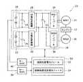
図1は、ハイブリッド車両における蓄電装置充放電制御システム10の構成を示す図である。この蓄電装置充放電制御システム10は、ハイブリッド車両の駆動源としてのエンジン12および2台の回転電機14,16と、2台の蓄電装置であるM蓄電装置20とS蓄電装置22を含み回転電機14,16に接続される電源回路18と、制御装置50とを備えて構成される。この蓄電装置充放電制御システム10は、2台の蓄電装置であるM蓄電装置20とS蓄電装置22の充放電制御を適切に実行する機能を有し、特に、2台の蓄電装置であるM蓄電装置20とS蓄電装置22の過充電、過放電を抑制しながらハイブリッド車両の運行を適切に行う機能を有する。 FIG. 1 is a diagram showing a configuration of a power storage device charge /
エンジン12は、回転電機14,16とともに車両の駆動源を構成する内燃機関である。エンジン12は、車両の車軸を駆動しタイヤを回転して走行を行わせる機能と共に、回転電機14,16を発電機として用いて発電を行わせ、電源回路18に含まれる2つの蓄電装置であるM蓄電装置20とS蓄電装置22を充電する機能を有する。エンジン12の制御は、図示されていないエンジン−ECUを介して制御装置50によって行われる。 The
回転電機14,16は、車両に搭載されるモータ・ジェネレータ(MG)であって、2つの蓄電装置であるM蓄電装置20とS蓄電装置22から電力が供給されるときはモータとして機能し、制動時には発電機として機能する三相同期型回転電機である。また、上記のようにエンジン12によって駆動されるときは発電機として機能する。 The rotating
回転電機14,16は区別しないで用いることもできるが、一方を2つの蓄電装置であるM蓄電装置20とS蓄電装置22の充電のための発電機、他方を主として車両走行用としてのモータとして用いることができる。すなわち、エンジン12によって一方の回転電機(MG1)14を駆動して発電機として用い、発電された電力を電源回路18を介して2つの蓄電装置であるM蓄電装置20とS蓄電装置22に供給し、他方の回転電機(MG2)16を車両走行のために用いて、力行時には2つの蓄電装置であるM蓄電装置20とS蓄電装置22から電力の供給を受けてモータとして機能して車両の車軸を駆動し、制動時には発電機として機能して回生エネルギを回収し、電源回路18を介して2つの蓄電装置であるM蓄電装置20とS蓄電装置22に供給するものとできる。回転電機14,16の制御は、図示されていないMG−ECUを介して制御装置50によって行われる。 The rotating
電源回路18は、2つの蓄電装置であるマスタ蓄電装置(M蓄電装置)20とスレーブ蓄電措置(S蓄電装置)22、2つの蓄電装置側平滑コンデンサ24,26、2つの電圧変換器であるM電圧変換器28とS電圧変換器30、インバータ側平滑コンデンサ32、2つのインバータであるMG1インバータ34とMG2インバータ36を含んで構成される。 The
ここで、M蓄電装置20とM電圧変換器28とは、正極側母線を共通とし、負極側母線を共通として直列に接続される。蓄電装置側平滑コンデンサ24は、この正極側母線と負極側母線を接続するように設けられ、M蓄電装置20とM電圧変換器28との間に配置される。同様に、S蓄電装置22とS電圧変換器30とは、正極側母線を共通とし、負極側母線を共通として直列に接続される。蓄電装置側平滑コンデンサ26は、この正極側母線と負極側母線を接続するように設けられ、S蓄電装置22とS電圧変換器30との間に配置される。 Here, the M
また、M電圧変換器28とMG1インバータ34とは、正極側母線を共通とし、負極側母線を共通として直列に接続される。そして、S電圧変換器30とMG1インバータ34も、正極側母線を共通とし、負極側母線を共通として直列に接続される。つまり、M電圧変換器28とS電圧変換器30とは、MG1インバータ34に対し、並列に接続される。 Further, the
また、MG1インバータ34とMG2インバータ36とは、正極側母線を共通とし、負極側母線を共通として、互いに接続される。つまり、MG1インバータ34とMG2インバータ36とは、並列に接続される。 In addition, the
この接続関係は、電圧変換器側とインバータ側との間に設けられる1組の正極母線と負極母線に対し、電圧変換側は、マスタとスレーブの2系列の蓄電装置−電圧変換器が並列に接続され、インバータ側は、MG1とMG2の2系列のインバータ−回転電機が並列に接続されるものである。換言すれば、2系列の蓄電装置が全体として1つの蓄電装置として機能しながら、2系列の回転電機に接続される接続関係である。 This connection is based on a pair of positive and negative buses provided between the voltage converter side and the inverter side, whereas the voltage conversion side has two power storage device-voltage converters in parallel: a master and a slave. On the inverter side, two series of inverter-rotary electric machines, MG1 and MG2, are connected in parallel. In other words, the connection relationship is such that the two series of power storage devices function as a single power storage device as a whole and are connected to the two series of rotating electrical machines.
M蓄電装置20とS蓄電装置22は、実質的には同じ形状、同じ性能を有する充放電可能な2次電池である。この場合、いずれをM蓄電装置とするかS蓄電装置とするかは決め事であって、どのようにしてもよい。もっとも、M蓄電装置20とS蓄電装置22とを異なる性能、例えばアンペアアワー容量が異なるものとしてもよい。その場合には、アンペアアワー容量の大きい方をマスタ蓄電装置(M蓄電装置)、小さい方をスレーブ蓄電装置(S蓄電装置)とすることができる。かかるM蓄電装置20、S蓄電装置22としては、例えば、約200Vの端子電圧を有するリチウムイオン組電池あるいはニッケル水素組電池、またはキャパシタ等を用いることができる。 The M
M電圧変換器28とS電圧変換器30は、M蓄電装置20とS蓄電装置22とが同じ性能を有するものであるときは、同じ性能の電圧変換機能を有する回路である。電圧変換器としては、リアクトルと制御装置50の制御の下で作動するスイッチング素子等を含んで構成することができる。電圧変換機能としては、蓄電装置側の電圧をリアクトルのエネルギ蓄積作用を利用して昇圧しインバータ側に供給する昇圧機能と、インバータ側からの電力を蓄電装置側に降圧して充電電力として供給する降圧機能とを有する。 When the M
M蓄電装置20とM電圧変換器28の間に設けられる蓄電装置側平滑コンデンサ24は、M蓄電装置20とM電圧変換器28との間における電圧、電流の変動を抑制し平滑化する機能を有する。S蓄電装置22とS電圧変換器30の間に設けられる蓄電装置側平滑コンデンサ26も同様の機能を有する。 The power storage device
MG1インバータ34とMG2インバータ36は、共に、交流電力と直流電力との間の電力変換を行う回路である。インバータとしては、制御装置50の制御の下で作動する複数のスイッチング素子を含んで構成される。上記の例で、回転電機(MG1)14を発電機として機能させるときは、MG1インバータ34は、回転電機(MG1)14からの交流三相回生電力を直流電力に変換し、蓄電装置側に充電電流として供給する交直変換機能を有する。また、MG2インバータ36は、車両が力行のとき、蓄電装置側からの直流電力を交流三相駆動電力に変換し、回転電機(MG2)16に駆動電力として供給する直交変換機能と、車両が制動のとき、逆に回転電機(MG2)16からの交流三相回生電力を直流電力に変換し、蓄電装置側に充電電流として供給する交直変換機能とを有する。 Both the
2つの電圧変換器と、2つのインバータの間に共通して設けられる1組の正極母線と負極母線との間に設けられるインバータ側平滑コンデンサ32は、この1組の正極母線と負極母線との間における電圧、電流の変動を抑制し平滑化する機能を有する。 The inverter-
M蓄電装置20と制御装置50との間に設けられるM−SOC38は、M蓄電装置20の充電状態値を取得して制御装置50に伝送する機能を有するものである。同様に、S蓄電装置22と制御装置50との間に設けられるS−SOC40は、S蓄電装置22の充電状態値を取得して制御装置50に伝送する機能を有するものである。かかるM−SOC38、S−SOC40としては、それぞれの蓄電装置についての充電電流、放電電流を検出し、これらを逐次積算して、それぞれの蓄電装置の充電容量に対し現在どの程度が充電されているかを求める演算装置で構成することができる。M−SOC38、S−SOC40を制御装置50の機能の一部として構成するものとしてもよい。 The M-
制御装置50は、上記の各要素の動作を全体として制御する機能を有し、上記のようにエンジン−ECU、MG−ECUを介してエンジン12、回転電機14,16の作動を制御する機能も有するが、ここでは特に、M蓄電装置20とS蓄電装置22の充放電を適切に制御する機能を有する。かかる制御装置50としては、車両搭載に適した制御回路を用いることができ、また、車両搭載に適したコンピュータを用いることができる。 The
制御装置50は、M蓄電装置20のSOC、あるいはS蓄電装置22のSOCのいずれか一方が予め定めた充電限界値と放電限界値との間から外れたときに、2台の蓄電装置を全体として強制的に放電あるいは充電を行う強制充放電モジュール52と、M蓄電装置20のSOC、あるいはS蓄電装置22のSOCのいずれか一方が予め定めた充電限界値と放電限界値との間にあって、他方がこの充電限界値と放電限界値との間から外れ、さらに予め定めた保護上限値と保護下限値との間からも外れたときに、過充電または過放電による特性劣化等から蓄電装置を保護するために、2台の蓄電装置に対し全体として強制的に保護放電あるいは保護充電を行う強制保護充放電モジュール54とを含んで構成される。 When either one of the SOC of M
かかる機能は、ソフトウェアによって実現でき、具体的には、対応する蓄電装置充放電制御プログラムを実行することで実現できる。かかる機能の一部をハードウェアで実現するものとしてもよい。 Such a function can be realized by software, specifically, by executing a corresponding power storage device charge / discharge control program. Some of these functions may be realized by hardware.
上記構成の作用、特に制御装置50の各機能について、図2から図6を用いて説明する。ここで図2から図4は、制御装置50の強制充放電モジュール52の機能の説明に関係する図であり、図5、図6は、制御装置50の強制保護充放電モジュール54の機能に関係する図である。 The operation of the above configuration, in particular, each function of the
図2は、M蓄電装置20のSOC、あるいはS蓄電装置22のSOCのいずれか一方が予め定めた充電限界値と放電限界値との間から外れたときに、適切に充放電する手順を示すフローチャートである。各手順は、上記の蓄電装置充放電制御プログラムの各処理手順に対応する。図3は、縦軸にSOC、横軸に時間をとって、充放電制御が行われるときの充電限界値と放電限界値との間である制御範囲60に対して、M蓄電装置20のSOC特性変化曲線64、S蓄電装置22のSOC特性変化曲線66の変化の様子を説明する図である。図4は、従来技術である平均SOCを用いて充放電制御を行う場合との比較を説明する図である。 FIG. 2 shows a procedure for appropriately charging and discharging when either the SOC of the M
図1で説明した構成において、M蓄電装置20とM電圧変換器28の系列と、S蓄電装置22とS電圧変換装置30の系列とは、2つの電圧変換器と2つのインバータとの間に設けられる共通の1組の正極母線と負極母線とにそれぞれ並列的に接続される。したがって、この1組の正極母線と負極母線から見れば、M蓄電装置20とM電圧変換器28の系列と、S蓄電装置22とS電圧変換装置30の系列とは、相互の間で電力分配が行われるが、その場合でも、全体としての電力量に変化はない。つまり、M蓄電装置20とM電圧変換器28の系列と、S蓄電装置22とS電圧変換装置30の系列は、1組の正極母線と負極母線から見れば、全体としての充放電制御が行われる。 In the configuration described with reference to FIG. 1, the series of the M
図3を用いてM蓄電装置20とS蓄電装置22に対する全体としての充放電制御を説明する。上記のように図3の縦軸にはSOCがとられているが、ここで、SOC−Cとして示されているのが、充放電制御における目標中心となるSOCの値で、いわゆる制御中心SOC値である。SOC−Uは、SOC−Cを中心として制御するときに実際のSOC値が追従変動するときのSOCの上限値で、これを充電限界値と呼ぶことができる。同様に、SOC−Lは、SOC−Cを中心として制御するときに実際のSOC値が追従変動するときのSOCの下限値で、これを放電限界値と呼ぶことができる。なお、以下では、SOCの値を単にSOCと呼ぶことにする。図3において、このSOC−UとSOC−Lの間の範囲が、SOC−Cを目標中心、すなわち制御中心として充放電制御を行うときの制御範囲60として示されている。 The overall charge / discharge control for the M
一例を上げると、SOC−Cを50%とし、SOC−Uを70%、SOC−Lを30%と予め設定することができる。 As an example, SOC-C can be set to 50%, SOC-U to 70%, and SOC-L to 30%.
このように、M蓄電装置20とS蓄電装置22に対する全体としての充放電制御は、この制御中心であるSOC−Cを目標として、M蓄電装置20のSOCとS蓄電装置22のSOCが共に、制御範囲60の間に収まるように実行される。これが図2における通常充放電制御(S10)である。具体的には、M蓄電装置20−M電圧変換器28の系列に出し入れされる電流と、S蓄電装置22−S電圧変換器30の系列に出し入れされる電流とが、共通の正極母線と負極母線で全体として1つの電流の出し入れとされ、この電流の出し入れで、M蓄電装置20とS蓄電装置22に対する全体としての充放電制御が行われる。 As described above, the overall charge / discharge control for the M
ここで、充電制御は、M蓄電装置20のSOCとS蓄電装置のSOCがSOC−Uを超さないように、SOC−Cを目標中心として制御するものであり、放電制御は、M蓄電装置20のSOCとS蓄電装置のSOCがSOC−Lを超さないように、SOC−Cを目標中心として制御するものである。このように、充電制御と放電制御とは、制御すべき電流の方向が相互に逆方向であることと、その限界値がSOC−UかSOC−Lかであるところが相違するのみであり、制御の実質的内容に大きな相違がない。そこで、以下では、放電制御に代表させて、その内容を説明する。 Here, the charge control is performed with SOC-C as a target center so that the SOC of the M
S10において通常の充放電制御が実行されると、その中で、M蓄電装置20のSOCがSOC−Lを超さないかが判断される(S12)。SOC−Lを超すとは、SOC−Lを超えてさらにSOCが低い値となることである。具体的には、M−SOC38を介してM蓄電装置20のSOCが取得され、あらかじめ定めたSOC−Lと比較される。上記の例では、M−SOC38を介して取得された値が30%未満か否かが判断される。S12の判断が肯定のときはS16に進む。 When normal charge / discharge control is executed in S10, it is determined whether the SOC of the M
S12の判断が否定のとき、つまりM蓄電装置20のSOCがSOC−Lを超さないでSOC−L以上のときはS14に進み、S蓄電装置22のSOCがSOC−Lを超さないかが判断される。S14の具体的内容は、S12と同様なものである。上記の例では、S−SOC40を介して取得された値が30%未満か否かが判断される。S14の判断が肯定のときはS17に進む。S14の判断が否定のときは、M蓄電装置20のSOCもS蓄電装置22のSOCも共にSOC−L以上であるので、S10に戻り、通常充放電制御が継続される。 When the determination in S12 is negative, that is, when the SOC of the M
S12の判断が肯定、またはS14の判断が肯定とは、M蓄電装置20のSOCか、S蓄電装置22のSOCか、いずれか一方がSOC−Lを超えてさらに低い値となっているときである。このときには、M蓄電装置20とS蓄電装置22の全体について強制的な充電が行われる(S16)。これによって、SOC−Lを超えてさらに低い値となっているSOCを有している蓄電装置に充電が行われ、そのSOCがSOC−Lを上回って、正常な制御範囲60の中に復帰することができる。 The determination of S12 is affirmative or the determination of S14 is affirmative when either the SOC of the M
そして、M蓄電装置20のSOCと、S蓄電装置22のSOCのいずれもが、予め定めた充電解除値であるSOC−B以上であるか否かが判断される(S18)。充電解除値SOC−Bは、強制充電を解除してもよいとされる程度にSOCがSOC−Lよりも高い値で、SOC−Cよりも低い値として、予め設定することができる。上記の例で、SOC−Cが50%、SOC−Lが30%のときは、充電解除値SOC−Bを40%と設定することができる。 Then, it is determined whether or not both the SOC of M
S18で判断が肯定されて、M蓄電装置20のSOCとS蓄電装置22のSOCが共にSOC−B以上となるときに、強制充電が解除される(S20)。このときには、M蓄電装置20のSOCもS蓄電装置22のSOCも既に制御範囲60の間にあるので、通常の充放電制御の状態に戻る。つまり、S10に戻る。 When the determination in S18 is affirmative and the SOC of the M
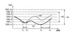
以上の様子が図3に示される。ここでは、縦軸にSOCをとり、横軸に時間をとり、細い実線でM蓄電装置20のSOC特性変化曲線64が示され、太い実線でS蓄電装置22のSOC特性変化曲線66が示されている。縦軸のSOCには、上記の例で、70%の充電限界値SOC−U、60%の放電解除値SOC−A、50%の制御中心SOC−C、40%の充電解除値SOC−B、30%の放電限界値SOC−Lが示されている。 The above situation is shown in FIG. Here, SOC is plotted on the vertical axis, time is plotted on the horizontal axis, the SOC
図3の例では、M蓄電装置20のSOCは、SOC−Cを目標中心として、制御範囲60の中にきれいに収まっている。一方S蓄電装置22のSOCは、時間t1でSOC−Lまで低下している。ここで、図2のフローチャートにおいて、S12が否定、S14が肯定となるので、S16においてM蓄電装置20とS蓄電装置22の全体に強制充電が行われる。この強制充電によってM蓄電装置20のSOCもS蓄電装置22のSOCも共に上昇し、時間t2において、S18の判断が肯定、すなわち、M蓄電装置20のSOCとS蓄電装置22のSOCが共にSOC−B以上となる。これによって、S20で説明したように、強制充電が解除される。In the example of FIG. 3, the SOC of the M
すなわち、時間t1から時間t2の間の短い期間に、強制充電が実行される。このように、ごく短い時間に限って強制充電が行われる。すなわち、この期間において、ハイブリッド車両において、エンジン12を始動させて回転電機14を駆動し、発電を行って、その電力で、M蓄電装置20とS蓄電装置22の全体に強制充電が行われる。これによって、上記の場合S蓄電装置22が過放電になることを抑制できる。また、強制充電を行う期間を最小にし、回転電機16によるいわゆるEV(Electric Vehicle)走行の期間をできるだけ長くすることができる。That is, forced charging is performed in a short period between time t1 and time t2 . Thus, forced charging is performed only for a very short time. That is, in this period, in the hybrid vehicle, the
図4は、上記の構成の作用と、従来技術である平均SOCを用いて全体としての充放電制御を行う方法の作用とを比較して説明する図である。ここでは、縦軸にSOCをとり、M蓄電装置20のSOCをM−SOCとして示し、S蓄電装置22のSOCをS−SOCとして示し、これら2つの蓄電装置のSOCの平均値、すなわち{(M−SOC)+(S−SOC)}/2を平均SOCとして、放電下限値SOC−Lとの比較をした図である。 FIG. 4 is a diagram illustrating a comparison between the operation of the above-described configuration and the operation of a method for performing charge / discharge control as a whole using the average SOC, which is a conventional technique. Here, the vertical axis indicates SOC, the SOC of the M
図4の例では、平均SOCはSOC−Lよりも高いので、従来技術の方法では、この状態において強制充電が行われない。このとき、M−SOCはSOC−Lよりも高いが、S−SOCはSOC−Lより低い。従来技術では、平均SOCがSOC−Lよりも高いので、予め定めた電力分配の仕方に従ってM蓄電装置20とS蓄電装置22から放電が行われ続ける。このように全体として放電が続けられることから、M蓄電装置20もS蓄電装置22もそのSOCが低下を続ける。M蓄電装置20のSOCはまだSOC−Lに対し余裕があるが、S蓄電装置22はすでにSOC−Lを割り込んでいる状態でさらにSOCが低下を続けるので、過放電に陥り、その特性の劣化が生じえる。 In the example of FIG. 4, since the average SOC is higher than SOC-L, the conventional method does not perform forced charging in this state. At this time, M-SOC is higher than SOC-L, but S-SOC is lower than SOC-L. In the prior art, since the average SOC is higher than SOC-L, the M
これに対し、図2で説明した処理手順をもちいると、図4の場合には、M蓄電装置20とS蓄電装置22のいずれか一方がSOC−Lを超えて低いSOCとなっているので、M蓄電装置20とS蓄電装置22の全体として強制充電が行われる。これによって、S蓄電装置22の過放電による特性劣化を防止することができる。 On the other hand, when the processing procedure described in FIG. 2 is used, in the case of FIG. 4, either the M
このように、図2の方法によれば、複数の蓄電装置のうち1つでもSOC−Lを超えて低いSOCとなると強制充電が行われるので、過放電を防止できる。同様にして、複数の蓄電装置のうち1つでも充電上限値SOC−Uを超えて高いSOCとなるときに強制放電を行うようにすることで、過充電を防止できる。 As described above, according to the method of FIG. 2, since any one of the plurality of power storage devices has a low SOC exceeding the SOC-L, the forced charge is performed, so that overdischarge can be prevented. Similarly, overcharging can be prevented by performing forced discharge when at least one of the plurality of power storage devices exceeds the charging upper limit SOC-U and becomes high SOC.
ところで、図2の方法によれば、複数の蓄電装置のなかに、制御範囲60の間にあるSOCを有している蓄電装置があっても、他に制御範囲60を超えている蓄電装置が1つでもあれば、強制充放電が行われる。ここで、複数の蓄電装置のなかに、制御範囲60の間にあるSOCを有している蓄電装置があれば、車両としては、EV走行を継続することができる。SOC−L、SOC−Uは、充放電制御に用いられる上限値と下限値であるので、蓄電装置の特性劣化が生じえるSOCはもう少し上限が高く、下限が低い。 By the way, according to the method of FIG. 2, among the plurality of power storage devices, even if there is a power storage device having an SOC between the control ranges 60, there are other power storage devices that exceed the
そこで、車両のEV走行をさらに延ばすために、複数の蓄電装置のなかに、少なくとも1つが制御範囲60に入っているSOCを有している蓄電装置があれば、その他の蓄電装置が制御範囲60を超えていても、まだ強制充電を行わないこともできる。そしてこの場合に、蓄電装置の過充電、過放電による特性劣化を防ぐために、予め保護範囲を定め、蓄電装置の1つでも保護上限値に達すれば強制的に保護放電を行い、1つでも保護下限値に達すれば強制的に保護充電を行うものとすればよい。 Therefore, in order to further extend the EV traveling of the vehicle, if there is a power storage device having an SOC in which at least one of the plurality of power storage devices is within the
また、通常の充放電制御を行っているときは、SOC−Cを目標中心として、制御範囲60の間にM蓄電装置20とS蓄電装置22のSOCが入るように制御が行われるのであるが、何らかの理由で、M蓄電装置20のSOCまたはS蓄電装置22のSOC、あるいは双方のSOCが制御範囲60を外れて、SOC−Uより高い値、SOC−Lより低い値になってしまうことが生じえる。このような異常事態のときにも、蓄電装置の過充電、過放電による特性劣化を防ぐために、予め保護範囲を定め、蓄電装置の1つでも保護上限値に達すれば強制的に保護放電を行い、1つでも保護下限値に達すれば強制的に保護充電を行うものとする必要がある。 In addition, when normal charge / discharge control is performed, control is performed so that the SOC of the M
したがって、充放電制御において、SOC−U、SOC−Lで規定される制御範囲の外側に保護範囲を設け、蓄電装置の1つでも保護上限値に達すれば強制的に保護放電を行い、1つでも保護下限値に達すれば強制的に保護充電を行うものとする。この機能は、制御装置50の強制保護充放電モジュール54の機能によって実行される。図2で説明したと同様に、充電側と放電側とは、限界値の設定等が異なるのみで、制御の実質的内容に大きな相違がない。そこで、以下では、放電制御に代表させて、その内容を説明する。 Therefore, in charge / discharge control, a protection range is provided outside the control range defined by SOC-U and SOC-L, and if one of the power storage devices reaches the protection upper limit value, the protection discharge is forcibly performed. However, if the protection lower limit is reached, the protection charge is forcibly performed. This function is executed by the function of the forced protection charge /
図5は、M蓄電装置20のSOC、あるいはS蓄電装置22のSOCのいずれか一方が制御範囲60にありながら、他方が予め定めた保護上限値と保護下限値との間から外れたときに、蓄電装置を保護するための充放電を実行する手順を示すフローチャートである。各手順は、上記の蓄電装置充放電制御プログラムの各処理手順に対応する。図6は、図3と同様に、縦軸にSOC、横軸に時間をとって、M蓄電装置20のSOC特性変化曲線68、S蓄電装置22のSOC特性変化曲線70の変化の様子を説明する図であり、ここでは保護上限値SOC−ULと保護下限値SOC−LLによって規定される保護範囲62が示されている。 FIG. 5 shows a case where either the SOC of the M
一例として、上記のようにSOC−Cを50%、SOC−Uを70%、SOC−Lを30%、SOC−Aを60%、SOC−Bを40%と予め設定する場合には、保護上限値SOC−ULを80%、保護下限値SOC−LLを20%と設定することができる。 As an example, if the SOC-C is 50%, the SOC-U is 70%, the SOC-L is 30%, the SOC-A is 60%, and the SOC-B is 40% as described above, The upper limit SOC-UL can be set to 80%, and the protection lower limit SOC-LL can be set to 20%.
図5のフローチャートにおいて、最初は通常の充放電制御が実行される状態である(S10)。この工程は、図2で説明した通常充放電制御と同じ内容で、M蓄電装置20とS蓄電装置22の全体について、SOC−Cを制御中心として、制御範囲60の間にそれぞれのSOCが入るように充放電制御が行われる。 In the flowchart of FIG. 5, the normal charge / discharge control is initially executed (S10). This process has the same contents as the normal charge / discharge control described with reference to FIG. 2, and each SOC enters between the control ranges 60 with the SOC-C as the control center for the entire M
S10で通常充放電制御が行われると、その中で、M蓄電装置20のSOCがSOC−Lを超して低い値であり、S蓄電装置22のSOCがSOC−Lを超して低い値であるか否かが判断される(S22)。すなわち、M蓄電装置20のSOCとS蓄電装置22のSOCのいずれもがSOC−Lを超さないかが判断される。 When normal charge / discharge control is performed in S10, the SOC of the M
S22で判断が肯定されると、M蓄電装置20とS蓄電装置22の全体について強制的に充電が実行される(S26)。この内容は図2で説明したS16の強制充電と同様のもので、全ての蓄電装置のSOCが制御範囲60を外れるときは、車両のEV走行に支障が出るので、エンジン12を始動させて強制的に充電を行うものである。図2のS16と異なるのは、S26においては全ての蓄電装置のSOCが制御範囲60を超えることを条件としているのに対し、S16は、いずれか1つの蓄電装置のSOCが制御範囲60を超えることを条件としていることである。 If the determination in S22 is affirmative, the entire M
また、S26の実行のあとは、再びS22に戻ることとし、強制充電によってSOCが上昇し、S22の条件が肯定されなくなると、強制充電を行わず、後述するS24の判断が行われる。つまり、S26の強制充電は、S22の条件が肯定される期間のみ行われる。これに対し、図2のS16は、強制充電によってS18の充電解除条件が満たされるまで充電が継続される。もっとも、S26においても、S18と同様な条件で充電を解除するものとしてもよい。 In addition, after the execution of S26, the process returns to S22 again. When the SOC increases due to the forced charge and the condition of S22 is not affirmed, the forced charge is not performed and the determination of S24 described later is performed. That is, the forced charge in S26 is performed only during a period in which the condition in S22 is affirmed. On the other hand, in S16 of FIG. 2, charging is continued until the charge release condition of S18 is satisfied by forced charging. But in S26, it is good also as what cancels | releases charge on the conditions similar to S18.
S22で判断が否定されると、次に、M蓄電装置20のSOCが保護下限値SOC−LLを超えて低い値となっているか、またはS蓄電装置22のSOCが保護下限値SOC−LLを超えて低い値となっているかが判断される(S24)。すなわち、M蓄電装置20のSOCとS蓄電装置22のSOCの少なくともいずれかがSOC−LLを超さないかが判断される。 If the determination in S22 is negative, then, the SOC of the M
S24で判断が肯定されると、蓄電装置の保護のための充電が強制的に行われる。この強制的な充電をS26の強制充電と区別して、強制保護充電(S27)と呼ぶことができる。強制保護充電は、M蓄電装置20とS蓄電装置22の全体に対して行われる。この強制保護充電によって、SOC−LLを超して低いSOCを有することになった蓄電装置が充電され、過放電による特性劣化を防止できる。 If the determination in step S24 is affirmative, charging for protecting the power storage device is forcibly performed. This forced charging is distinguished from forced charging in S26 and can be called forced protection charging (S27). The forced protection charging is performed on the entire M
S24で判断が否定されると、S10に戻り、引き続きS22の判断、S24の判断が行われる。いずれかの判断が肯定されるまでは、強制的な充電が行われず、通常の充放電制御が続けられる。これにより、いずれかの蓄電装置が制御範囲60の中にあれば、他の蓄電装置が制御範囲60を外れていてもS24の判断が肯定されない限り、強制充電、つまりエンジン12の始動を要せず、車両のEV走行を継続することができる。 If the determination is negative in S24, the process returns to S10, and the determination in S22 and the determination in S24 are continued. Until either determination is affirmed, the forcible charging is not performed and the normal charge / discharge control is continued. As a result, if any one of the power storage devices is within the
そして、M蓄電装置20のSOCと、S蓄電装置22のSOCのいずれもが、予め定めた充電解除値であるSOC−B以上であるか否かが判断される(S28)。この工程の内容は図2のS18で説明したものと同様のものである。 Then, it is determined whether or not both the SOC of M
S28で判断が肯定されて、M蓄電装置20のSOCとS蓄電装置22のSOCが共にSOC−B以上となるときに、強制充電が解除される(S30)。このときには、M蓄電装置20のSOCもS蓄電装置22のSOCも既に制御範囲60の間にあるので、通常の充放電制御の状態に戻る。つまり、S10に戻る。 When the determination in S28 is affirmative and the SOC of the M
上記では、強制保護充電を解除する充電解除値を図2、図3で説明した充電解除値SOC−Bと同じとしたが、これを、SOC−LLよりも高く、SOC−Lと同じ値またはこれより低い値として設定することもできる。このようにすることで、強制保護充電の期間をより短くし、車両のEV走行への復帰を早めることができる。 In the above description, the charge release value for releasing the forced protection charge is the same as the charge release value SOC-B described in FIGS. 2 and 3, but this is higher than the SOC-LL and the same value as the SOC-L or It can also be set as a lower value. By doing in this way, the period of forced protection charge can be shortened, and the return to the EV running of the vehicle can be accelerated.
以上の様子が図6に示される。図6は図3と同様に、縦軸にSOCをとり、横軸に時間をとり、細い実線でM蓄電装置20のSOC特性変化曲線68が示され、太い実線でS蓄電装置22のSOC特性変化曲線70が示されている。縦軸のSOCには、図3で説明した例で、70%の充電限界値SOC−U、60%の放電解除値SOC−A、50%の制御中心SOC−C、40%の充電解除値SOC−B、30%の放電限界値SOC−Lに加えて、80%の保護上限値SOC−UL、20%の保護下限値SOC−LLが示されている。 The above situation is shown in FIG. As in FIG. 3, the vertical axis indicates SOC, the horizontal axis indicates time, the thin solid line indicates the SOC
図6の例では、初期のときに、M蓄電装置20のSOCとS蓄電装置22のSOCが共に次第に低下し、時間t3の手前で蓄電装置20のSOCがSOC−Lを超えて低いSOCとなり、時間t3においてS蓄電装置22のSOCもSOC−Lを超えて低いSOCとなったことが示されている。この時間t3において図5のS22が肯定されるので、M蓄電装置20とS蓄電装置22の全体について強制充電が開始される。In the example of FIG. 6, the SOC of the M
これによって、M蓄電装置20のSOCとS蓄電装置22のSOCが共に上昇をはじめ、時間t4で蓄電装置20のSOCがSOC−Lよりも高い値となって制御範囲60の中に復帰し、時間t4の後でS蓄電装置22のSOCもSOC−Lよりも高い値となって制御範囲60の中に復帰したことが示されている。ここで時間t4において図5のS22が肯定されなくなるので、S26で説明した強制充電が停止される。As a result, both the SOC of the M
時間t4の後において、M蓄電装置20のSOCは、SOC−Cを目標中心として、制御範囲60の中にきれいに収まっている。一方S蓄電装置22のSOCは、一旦SOC−Lよりも高い値となって制御範囲60に復帰したものの、またSOC−Lを超えて低い値となり、さらに低下を続け、時間t5においてSOC−LLに達したことが図6で示されている。After time t4 , the SOC of the M
時間t5においては、M蓄電装置20のSOCが制御範囲60の間にとどまっているのに対し、S蓄電装置22のSOCがSOC−LLを超えて低い値となっている。つまり図5のS24の判断が肯定される状態であるので、ここでS27の強制保護充電が実行される。これによってS蓄電装置22のSOCは上昇を始め、時間t6でSOC−Bに到達する様子が図6に示されている。この時間t6において図5のS28の判断が肯定されることとなるので、強制保護充電が解除される。At time t5 , the SOC of the M
図6の例では、時間t3から時間t4の間の短い期間にS26の強制充電が実行され、時間t5から時間t6の間の短い期間に、強制保護充電が実行される。このように、ごく短い時間に限って強制充電と強制保護充電が行われる。すなわち、これらの期間において、ハイブリッド車両において、エンジン12を始動させて回転電機14を駆動し、発電を行って、その電力で、M蓄電装置20とS蓄電装置22の全体に強制充電が行われる。これによって、上記の場合S蓄電装置22が過放電のために特性劣化となることを抑制できる。また、強制充電および強制保護充電を行う期間を最小にし、回転電機16によるいわゆるEV(Electric Vehicle)走行の期間をできるだけ長くすることができる。In the example of FIG. 6, the forced charging is executed in S26 in a short period of between from the time t3 of the time t4, the short period of between from the time t5 the time t6, Force protection charging is performed. Thus, forced charging and forced protection charging are performed only for a very short time. That is, in these periods, in the hybrid vehicle, the
このように、図5の方法によれば、複数の蓄電装置のうち1つでも制御範囲60にSOCがあれば、強制充電を行わないこととし、その場合に他の蓄電装置がSOC−LLを超えて低いSOCとなると強制保護充電が行われるので、車両のEV走行の期間を延ばしながら、蓄電装置における過放電による特性劣化を防止できる。同様にして、複数の蓄電装置のうち1つでも制御範囲60にSOCがあれば、強制放電を行わないこととし、その場合に他の蓄電装置がSOC−ULを超えて高いSOCとなると強制保護放電を行うようにすることで、車両のEV走行の期間を延ばしながら、蓄電装置における過充電による特性劣化を防止できる。 As described above, according to the method of FIG. 5, if at least one of the plurality of power storage devices has SOC in the
10 蓄電装置充放電制御システム、12 エンジン、14,16 回転電機、18 電源回路、20 M蓄電装置、22 S蓄電装置、24,26 蓄電装置側平滑コンデンサ、28 M電圧変換器、30 S電圧変換器、32 インバータ側平滑コンデンサ、34 MG1インバータ、36 MG2インバータ、38 M−SOC、40 S−SOC、50 制御装置、52 強制充放電モジュール、54 強制保護充放電モジュール、60 制御範囲、62 保護範囲、64,66,68,70 SOC特性変化曲線。 DESCRIPTION OF
Claims (5)
Translated fromJapanese各蓄電装置の充電状態値を取得する手段と、
各蓄電装置の充電状態値を予め定めた充電限界値および予め定めた放電限界値と比較する手段と、
いずれか1つの蓄電装置の充電状態値が充電限界値を超えるときに、複数の蓄電装置の全体に対し強制的に放電を行い、または、いずれか1つの蓄電装置の充電状態値が放電限界値を超えるときに、複数の蓄電装置の全体に対し強制的に充電を行う強制充放電手段と、
を備えることを特徴とする蓄電装置充放電制御システム。A plurality of power storage devices in which charge / discharge control is performed as a whole;
Means for obtaining a charge state value of each power storage device;
Means for comparing the charge state value of each power storage device with a predetermined charge limit value and a predetermined discharge limit value;
When the charge state value of any one power storage device exceeds the charge limit value, the entire plurality of power storage devices are forcibly discharged, or the charge state value of any one power storage device is the discharge limit value A forced charging / discharging means for forcibly charging the whole of the plurality of power storage devices,
An electrical storage device charge / discharge control system comprising:
いずれか1つの蓄電装置の充電状態値が充電限界値を超えたための強制放電によって充電状態値が低下し、各蓄電装置の充電状態値のすべてが予め定めた強制放電解除値以下となるときに強制放電を止めて通常の充放電制御に戻し、または、いずれか1つの蓄電装置の充電状態値が放電限界値を超えたための強制充電によって充電状態値が上昇し、各蓄電装置の充電状態値のすべてが予め定めた充電解除値以上となるときに強制充電を止めて通常の充放電制御に戻す強制充放電解除手段を備えることを特徴とする蓄電装置充放電制御システム。The power storage device charge / discharge control system according to claim 1,
When the charge state value decreases due to forced discharge because the charge state value of any one power storage device exceeds the charge limit value, and all of the charge state values of each power storage device are equal to or less than a predetermined forced discharge release value Stop the forced discharge and return to normal charge / discharge control, or the charge state value rises due to the forced charge because the charge state value of any one power storage device exceeds the discharge limit value, and the charge state value of each power storage device A power storage device charge / discharge control system comprising forced charge / discharge release means for stopping forced charge and returning to normal charge / discharge control when all of the above are equal to or greater than a predetermined charge release value.
各蓄電装置の充電状態値を取得する手段と、
各蓄電装置の充電状態値を予め定めた充電限界値および予め定めた放電限界値と比較する手段と、
各蓄電装置の充電状態値がすべて充電限界値または放電限界値を超えるときに、複数の蓄電装置の全体に対し放電または充電を行う充放電手段と、
少なくとも1つの蓄電装置の充電状態値が充電限界値を超えていない一方で、充電限界値を超えているいずれか1つの蓄電装置がさらに予め定めた保護上限値を超えるときに、複数の蓄電装置の全体に対し強制的な保護放電を行い、または、少なくとも1つの蓄電装置の充電状態値が放電限界値を超えていない一方で、放電限界値を超えているいずれか1つの蓄電装置がさらに予め定めた保護下限値を超えるときに、複数の蓄電装置の全体に対し強制的な保護充電を行う強制保護充放電手段を備えることを特徴とする蓄電装置充放電制御システム。A plurality of power storage devices in which charge / discharge control is performed as a whole;
Means for obtaining a charge state value of each power storage device;
Means for comparing the charge state value of each power storage device with a predetermined charge limit value and a predetermined discharge limit value;
Charge / discharge means for discharging or charging the whole of the plurality of power storage devices when all the charge state values of the power storage devices exceed the charge limit value or the discharge limit value
A plurality of power storage devices when the charge state value of at least one power storage device does not exceed the charge limit value, but any one power storage device exceeding the charge limit value further exceeds a predetermined protection upper limit value Or the charge state value of at least one power storage device does not exceed the discharge limit value, while any one power storage device exceeding the discharge limit value is further A power storage device charge / discharge control system, comprising: a forced protection charge / discharge unit that forcibly protects and charges the whole of the plurality of power storage devices when a predetermined protection lower limit value is exceeded.
いずれか1つの蓄電装置の充電状態値が保護上限値を超えたために強制保護放電を行い、それによって充電状態値が低下し、各蓄電装置の充電状態値のすべてが予め定めた保護放電解除値以下となるときに強制保護放電を止めて通常の充放電制御に戻し、または、いずれか1つの蓄電装置の充電状態値が保護下限界値を超えたために強制保護充電を行い、それによって充電状態値が上昇し、各蓄電装置の充電状態値のすべてが予め定めた保護充電解除値以上となるときに強制保護充電を止めて通常の充放電制御に戻す強制保護充放電解除手段を備えることを特徴とする蓄電装置充放電制御システム。The power storage device charge / discharge control system according to claim 3,
Forcible protective discharge is performed because the charge state value of any one power storage device exceeds the protection upper limit value, thereby reducing the charge state value, and all of the charge state values of the respective power storage devices are predetermined protection discharge release values. Stop forced protection discharge and return to normal charge / discharge control when the following conditions are met, or perform forced protection charging because the charge state value of any one power storage device exceeds the lower limit of protection, thereby charging state A forcible protection charge / discharge release means for stopping the forced protection charge and returning to normal charge / discharge control when the value rises and all of the charge state values of each power storage device are equal to or greater than a predetermined protection charge release value A power storage device charge / discharge control system.
保護放電解除値は、充電限界値よりも低い値に設定され、保護充電解除値は、放電限界値よりも高い値に設定されることを特徴とする蓄電装置充放電制御システム。The power storage device charge / discharge control system according to claim 4,
The protection discharge release value is set to a value lower than the charge limit value, and the protection charge release value is set to a value higher than the discharge limit value.
Priority Applications (1)
| Application Number | Priority Date | Filing Date | Title |
|---|---|---|---|
| JP2008180049AJP2010022128A (en) | 2008-07-10 | 2008-07-10 | Charge/discharge control system for electric storage device |
Applications Claiming Priority (1)
| Application Number | Priority Date | Filing Date | Title |
|---|---|---|---|
| JP2008180049AJP2010022128A (en) | 2008-07-10 | 2008-07-10 | Charge/discharge control system for electric storage device |
Publications (1)
| Publication Number | Publication Date |
|---|---|
| JP2010022128Atrue JP2010022128A (en) | 2010-01-28 |
Family
ID=41706479
Family Applications (1)
| Application Number | Title | Priority Date | Filing Date |
|---|---|---|---|
| JP2008180049APendingJP2010022128A (en) | 2008-07-10 | 2008-07-10 | Charge/discharge control system for electric storage device |
Country Status (1)
| Country | Link |
|---|---|
| JP (1) | JP2010022128A (en) |
Cited By (9)
| Publication number | Priority date | Publication date | Assignee | Title |
|---|---|---|---|---|
| EP2383142A2 (en) | 2010-04-28 | 2011-11-02 | Toyota Jidosha Kabushiki Kaisha | Power limiting apparatus for electric system, power limiting method for electric system and electric system |
| JP2012143151A (en)* | 2010-03-23 | 2012-07-26 | Nec Corp | Method for charging/discharging lithium-ion secondary battery, and charging/discharging system |
| US8260564B2 (en) | 2010-04-15 | 2012-09-04 | Toyota Jidosha Kabushiki Kaisha | Apparatus for calculating state of charge, method of calculating state of charge, and electric system |
| JP2013137935A (en)* | 2011-12-28 | 2013-07-11 | Toyota Motor Corp | Non-aqueous secondary battery control device and control method |
| JP2014103831A (en)* | 2012-11-22 | 2014-06-05 | Mitsubishi Heavy Ind Ltd | Device, method, and program for controlling power storage system, and power storage system with the same |
| WO2015011533A1 (en)* | 2013-07-22 | 2015-01-29 | Toyota Jidosha Kabushiki Kaisha | Vehicle and control method for vehicle |
| CN108357374A (en)* | 2017-01-27 | 2018-08-03 | 通用汽车环球科技运作有限责任公司 | System and method for managing battery charging state |
| US10065509B2 (en) | 2014-10-30 | 2018-09-04 | Hyundai Motor Company | Circuit for controlling low power DC-DC converter of hybrid vehicle and method for controlling low power DC-DC converter |
| JP7537539B1 (en) | 2023-02-06 | 2024-08-21 | いすゞ自動車株式会社 | Control device and vehicle |
- 2008
- 2008-07-10JPJP2008180049Apatent/JP2010022128A/enactivePending
Cited By (11)
| Publication number | Priority date | Publication date | Assignee | Title |
|---|---|---|---|---|
| JP2012143151A (en)* | 2010-03-23 | 2012-07-26 | Nec Corp | Method for charging/discharging lithium-ion secondary battery, and charging/discharging system |
| US8260564B2 (en) | 2010-04-15 | 2012-09-04 | Toyota Jidosha Kabushiki Kaisha | Apparatus for calculating state of charge, method of calculating state of charge, and electric system |
| EP2383142A2 (en) | 2010-04-28 | 2011-11-02 | Toyota Jidosha Kabushiki Kaisha | Power limiting apparatus for electric system, power limiting method for electric system and electric system |
| US8502411B2 (en) | 2010-04-28 | 2013-08-06 | Toyota Jidosha Kabushiki Kaisha | Power limiting apparatus for electric system, power limiting method for electric system and electric system |
| JP2013137935A (en)* | 2011-12-28 | 2013-07-11 | Toyota Motor Corp | Non-aqueous secondary battery control device and control method |
| JP2014103831A (en)* | 2012-11-22 | 2014-06-05 | Mitsubishi Heavy Ind Ltd | Device, method, and program for controlling power storage system, and power storage system with the same |
| WO2015011533A1 (en)* | 2013-07-22 | 2015-01-29 | Toyota Jidosha Kabushiki Kaisha | Vehicle and control method for vehicle |
| US10065509B2 (en) | 2014-10-30 | 2018-09-04 | Hyundai Motor Company | Circuit for controlling low power DC-DC converter of hybrid vehicle and method for controlling low power DC-DC converter |
| CN108357374A (en)* | 2017-01-27 | 2018-08-03 | 通用汽车环球科技运作有限责任公司 | System and method for managing battery charging state |
| CN108357374B (en)* | 2017-01-27 | 2021-03-02 | 通用汽车环球科技运作有限责任公司 | System and method for managing battery state of charge |
| JP7537539B1 (en) | 2023-02-06 | 2024-08-21 | いすゞ自動車株式会社 | Control device and vehicle |
Similar Documents
| Publication | Publication Date | Title |
|---|---|---|
| KR101924252B1 (en) | Electric power supply device | |
| US8639413B2 (en) | Vehicle power supply system and method for controlling the same | |
| JP5510283B2 (en) | Power storage unit protection system for vehicles | |
| US9007001B2 (en) | Power supply system and vehicle equipped with power supply system | |
| EP2444269B1 (en) | Electric vehicle and method for controlling electric vehicle | |
| EP2353920B1 (en) | Electrically driven vehicle and electrically driven vehicle control method | |
| JP2010022128A (en) | Charge/discharge control system for electric storage device | |
| CN102202947B (en) | Hybrid vehicle and control method for hybrid vehicle | |
| CN102202931B (en) | Electric power source system for electrically driven vehicle and its control method | |
| JP5382238B2 (en) | Hybrid vehicle and control method thereof | |
| CN103813928A (en) | Battery processing device, vehicle, battery processing method, and battery processing program | |
| JPWO2012131864A1 (en) | Electric vehicle and control method thereof | |
| JP2010028886A (en) | System for controlling charge and discharge of energy storage device | |
| JP5141417B2 (en) | Power storage device charge / discharge control system | |
| JP2012050281A (en) | Battery charging system of electric vehicle | |
| EP3674129B1 (en) | Vehicular charging control system | |
| JP2010174775A (en) | Vehicle control device | |
| JP7322772B2 (en) | battery system | |
| JP2017216796A (en) | Electric vehicle | |
| JP2010166760A (en) | Power supply system | |
| JP6195320B2 (en) | Power storage device charge / discharge control system | |
| JP2019087423A (en) | Battery system | |
| JP2011223719A (en) | Power supply apparatus | |
| KR20180023327A (en) | Power supply apparatus for electric field load in eco-vehicle | |
| JP6322417B2 (en) | Voltage fluctuation control device |
Legal Events
| Date | Code | Title | Description |
|---|---|---|---|
| A711 | Notification of change in applicant | Free format text:JAPANESE INTERMEDIATE CODE: A711 Effective date:20100405 | |
| A521 | Written amendment | Free format text:JAPANESE INTERMEDIATE CODE: A821 Effective date:20100406 |