JP2010020370A - Pos terminal device - Google Patents
Pos terminal deviceDownload PDFInfo
- Publication number
- JP2010020370A JP2010020370AJP2008177584AJP2008177584AJP2010020370AJP 2010020370 AJP2010020370 AJP 2010020370AJP 2008177584 AJP2008177584 AJP 2008177584AJP 2008177584 AJP2008177584 AJP 2008177584AJP 2010020370 AJP2010020370 AJP 2010020370A
- Authority
- JP
- Japan
- Prior art keywords
- terminal device
- pos terminal
- unit
- customer
- pedestal
- Prior art date
- Legal status (The legal status is an assumption and is not a legal conclusion. Google has not performed a legal analysis and makes no representation as to the accuracy of the status listed.)
- Pending
Links
Images


Landscapes
- Cash Registers Or Receiving Machines (AREA)
Abstract
Description
Translated fromJapanese本発明は、POS端末装置の店舗内におけるレイアウトの汎用性を向上させる技術に関する。 The present invention relates to a technique for improving the versatility of a layout of a POS terminal device in a store.
スーパーやコンビニエンスストア等の店舗では、顧客によって購入される商品の売価を積算するためにPOS端末装置が用いられている。店員は、顧客が購入する目的でレジカウンターに持参した商品をPOS端末装置に読み取らせるとともに、当該顧客に対して請求すべき金額(商品の購入額)を提示して、当該商品の販売代金を徴収する。なお、店舗において店員がPOS端末装置を操作する場合、顧客に対する接客重視の観点から、対面式のレジカウンターを採用するのが一般的である。 In stores such as supermarkets and convenience stores, POS terminal devices are used to integrate the selling prices of products purchased by customers. The store clerk makes the POS terminal device read the product brought to the checkout counter for the purpose of purchase by the customer, presents the amount to be charged to the customer (the purchase amount of the product), and pays the sales price of the product Collect. When a store clerk operates a POS terminal device in a store, it is common to employ a face-to-face cash register counter from the viewpoint of customer service.
一方、昨今、POS端末装置を扱う店員の人数を削減することにより人件費を削減することを目的として、顧客が操作することを想定したPOS端末装置が登場してきた。さらには、営業形態に応じて、店員が操作する「接客モード(店員モード)」と、顧客が操作する「セルフモード」との間で、動作モードを切り替えることが可能なPOS端末装置も登場してきた。このようなPOS端末装置(レジ)が、例えば特許文献1に記載されている。 On the other hand, recently, a POS terminal device that is assumed to be operated by a customer has been introduced for the purpose of reducing labor costs by reducing the number of shop assistants handling the POS terminal device. Furthermore, POS terminal devices that can switch the operation mode between a “customer service mode (store clerk mode)” operated by a store clerk and a “self mode” operated by a customer have appeared. It was. Such a POS terminal device (register) is described in
ところが、特許文献1に記載されているPOS端末装置は、動作モードに関わらず、一方向からしか操作できない構造であり、動作モードを変更した場合でも操作者の立ち位置を変更することのできない構造となっている。 However, the POS terminal device described in
したがって、対面式のレジカウンターに特許文献1に記載のPOS端末装置を設置した場合、当該POS端末装置が接客モードのとき、操作者でない顧客は、店員と対向する位置に立つ必要がある。一方、当該POS端末装置がセルフモードのとき、操作者となる顧客は、接客モードにおける店員の立ち位置に立つ必要がある。すなわち、顧客は、POS端末装置の動作モードを判断して、動作モードに応じた位置に出向いて料金の支払いをしなければならいない。 Therefore, when the POS terminal device described in
また、店員の立ち位置がレジカウンター内部(顧客を立ち入らせることが好ましくない空間)に設けられることの多いコンビニエンスストア等では、POS端末装置を「セルフモード」に切り替える際には、POS端末装置全体をレジカウンターの外部(顧客側)に向ける作業が必要となる。一般に、POS端末装置の技術分野では、防犯上の理由から、POS端末装置を容易に移動させることが可能な構造とすることには消極的である。したがって、POS端末装置全体をレジカウンターの外部に向けるために当該POS端末装置を移動させる作業は、作業者にとって負担の大きな作業となる。 In addition, in a convenience store or the like where the clerk's standing position is often provided inside a cashier counter (a space where it is not desirable for customers to enter), when switching the POS terminal device to the “self mode”, the entire POS terminal device Work to point the outside of the cashier counter (customer side). In general, in the technical field of POS terminal devices, for security reasons, the POS terminal device is reluctant to have a structure that can be easily moved. Therefore, the work of moving the POS terminal device in order to direct the entire POS terminal device to the outside of the checkout counter is a burdensome work for the operator.
すなわち、特許文献1に記載されているPOS端末装置では、営業形態に応じて動作モードを変更することは可能であるものの、営業形態に応じたレイアウト変更に対応できないという問題があった。 In other words, the POS terminal device described in
本発明は、上記課題に鑑みてなされたものであり、レイアウト変更が容易にできるPOS端末装置を提供することを目的とする。 The present invention has been made in view of the above problems, and an object of the present invention is to provide a POS terminal device capable of easily changing the layout.
上記の課題を解決するため、請求項1の発明は、顧客によって購入される商品の売価を積算するPOS端末装置であって、台座部と、操作者によって操作される操作部と、前記操作部の前記台座部に対する向きを変更することが可能なように、前記操作部を連結する連結機構とを備えることを特徴とする。 In order to solve the above problems, the invention of
また、請求項2の発明は、請求項1の発明に係るPOS端末装置であって、金銭を内部に収納する収納部をさらに備え、前記連結機構は、前記操作部とともに、前記収納部の向きを変更することを特徴とする。 The invention of
また、請求項3の発明は、請求項1の発明に係るPOS端末装置であって、金銭を内部に収納する収納部をさらに備え、前記収納部は前記台座部に対して固定されていることを特徴とする。 The invention of
また、請求項4の発明は、請求項1ないし3のいずれかの発明に係るPOS端末装置であって、前記操作部の向きを検出する検出手段と、前記検出手段の検出結果に応じて、前記操作部を顧客が操作するセルフモードと前記操作部を店員が操作する接客モードとの間で動作モードを切り替える切替手段とをさらに備えることを特徴とする。 Further, the invention of
請求項1ないし請求項4に記載の発明は、操作部の台座部に対する向きを変更することが可能なように、操作部を連結する連結機構を備えることにより、POS端末装置のレイアウトの汎用性が向上するとともに、レイアウトの切り替え作業を容易に行うことができる。 According to the first to fourth aspects of the invention, the versatility of the layout of the POS terminal device is provided by providing a connection mechanism for connecting the operation units so that the direction of the operation unit with respect to the pedestal unit can be changed. As a result, the layout switching operation can be easily performed.
請求項3に記載の発明は、収納部は台座部に対して固定されていることにより、セキュリティを向上させることができる。 According to the third aspect of the present invention, the storage portion is fixed with respect to the pedestal portion, so that security can be improved.
請求項4に記載の発明は、操作部の向きを検出する検出手段の検出結果に応じて、操作部を顧客が操作するセルフモードと操作部を店員が操作する接客モードとの間で動作モードを切り替えることにより、作業者の負担を軽減することができる。 According to a fourth aspect of the present invention, there is provided an operation mode between a self mode in which the customer operates the operation unit and a customer service mode in which the store clerk operates the operation unit according to the detection result of the detection means for detecting the direction of the operation unit. By switching, the burden on the operator can be reduced.
以下、本発明の好適な実施の形態について、添付の図面を参照しつつ、詳細に説明する。 DESCRIPTION OF EXEMPLARY EMBODIMENTS Hereinafter, preferred embodiments of the invention will be described in detail with reference to the accompanying drawings.
<1. 第1の実施の形態>
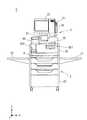
図1は、第1の実施の形態におけるPOS端末装置1を示す斜視図である。また、図2は、POS端末装置1の正面図である。<1. First Embodiment>
FIG. 1 is a perspective view showing a
なお、図1および図2において、図示および説明の都合上、Z軸方向が鉛直方向を表し、XY平面が水平面を表すものとして定義する。ただし、これらの方向は位置関係を把握するために便宜上定義するものであって、以下に説明する各方向を限定するものではない。以下の各図についても同様である。 In FIGS. 1 and 2, for convenience of illustration and description, the Z-axis direction is defined as the vertical direction, and the XY plane is defined as the horizontal plane. However, these directions are defined for convenience in order to grasp the positional relationship, and do not limit each direction described below. The same applies to the following drawings.
図1および図2に示すように、POS端末装置1は、台座部2、レジ部3および連結機構4を備えており、これらが互いに組み合わさって一体構造物を形成している。詳細は後述するが、POS端末装置1は、顧客によって購入される商品の売価を積算する装置として構成されている。なお、以下の説明において、店員によって操作されることを想定して設定されるPOS端末装置1の動作モードを「接客モード」と称し、顧客によって操作されることを想定して設定されるPOS端末装置1の動作モードを「セルフモード」と称する。 As shown in FIGS. 1 and 2, the
台座部2は、筐体20と一対の載置台21,22とを備えている。台座部2は、店舗内の床面に対してレジ部3を支持する機能を有しており、いわゆる接客用のカウンターを形成している。 The
筐体20はレジ袋や割り箸といった小物類を収納しておく複数の引き出しを備えている。これらの引き出しは必要に応じて、筐体20の内部から(+Y)方向に引き出すことが可能である。また、筐体20の上部には、図2に示すように、連結機構4を介してレジ部3が取り付けられている。 The
台座部2のX軸方向の両端部に設けられている載置台21,22には、精算に係る商品が載置される。顧客は店舗内を巡回しつつ、陳列されている商品(販売に供されている商品)の中から購入しようとする商品を選択して買い物カゴに投入する。そして商品の選択が終了すると、顧客は、当該商品が投入された買い物カゴを台座部2の載置台21(または載置台22)に置き、商品の購入代金を支払う。すなわち、顧客が購入しようとする商品は、通常、買い物カゴに投入された状態で載置台21(または載置台22)に載置される。 On the mounting tables 21 and 22 provided at both ends of the
レジ部3は、収納部30、ボタン群31、ディスプレイ32、スキャナ33、カードリーダ34、電子マネー読取部35およびプリンタ36を備えている。なお、本実施の形態におけるPOS端末装置1では、レジ部3の備えるボタン群31、ディスプレイ32、スキャナ33、カードリーダ34、電子マネー読取部35およびプリンタ36は、いずれもPOS端末装置1の操作者によって操作されうる構成であり、本発明の操作部に相当する。 The
図1において収納部30の(+Y)側の面には、硬貨収受部300および紙幣収受部301が設けられている。詳細は図示しないが、硬貨収受部300は、顧客から受領した硬貨を収納部30の内部に収納するための投入口、および、顧客に対して釣り銭としての硬貨を払い出す受け皿から構成されている。また、紙幣収受部301は、顧客から受領した紙幣を収納部30の内部に収納するとともに、顧客に対して釣り銭としての紙幣を払い出す機能を有している。すなわち、硬貨収受部300および紙幣収受部301は、操作者によって貨幣の出し入れ操作がされるため、本発明における操作部に相当する。 In FIG. 1, a
詳細は図示していないが、ボタン群31は複数のキー(操作ボタン)を備えている。本実施の形態におけるボタン群31は、POS端末装置1の基本設定等を変更するために操作される。すなわち、ボタン群31は、店舗側の操作者(作業者または店員等であって顧客ではない者)にのみ操作を許可すべき操作部である。したがって、本実施の形態におけるPOS端末装置1では、接客モードにおいてボタン群31が有効に設定され、セルフモードにおいてボタン群31が無効に設定される。 Although details are not shown, the
ディスプレイ32は、タッチパネル式の液晶パネルであって、制御部10による制御に従って各種情報を画面に表示するとともに、操作者が画面の所定位置に触れることによって、所定の情報が入力できるように構成されている。すなわち、ディスプレイ32は、操作者によって所定の情報についての入力操作がされるため、先述のように、本発明における操作部に相当する。 The
スキャナ33は、個々の商品に添付されているバーコードを読み取ることにより、商品情報を取得する。店舗で扱う商品には、それぞれバーコードが印字されるか、あるいはバーコードが印字されたラベルが貼付されている。商品に添付されるバーコードは、当該商品を個々に識別するための識別コードを形成しており、POS端末装置1は、識別コードによって示される商品の商品情報(商品名や売価等)を検索できるように構成されている。すなわち、スキャナ33は、操作者によってバーコードの読み取り操作がされるため、先述のように、本発明における操作部に相当する。 The
なお、商品に添付されているバーコードに含まれる情報は識別コードに限定されるものではなく、商品の売価を示す情報やチェックデジット等が含まれていてもよい。また、バーコードを添付できない一部の商品については、先述のディスプレイ32に表示されるタッチボタンを操作者が操作することにより、当該商品の識別コードがPOS端末装置1に入力される。 Note that the information included in the barcode attached to the product is not limited to the identification code, and may include information indicating the selling price of the product, a check digit, and the like. For some products to which a barcode cannot be attached, the operator operates a touch button displayed on the
カードリーダ34は、顧客が持参するカード(会員カードやポイントカード、クレジットカード等)から情報を読み取る。すなわち、カードリーダ34は、操作者によってカードに記憶されている情報の読み取り操作がされるため、先述のように、本発明における操作部に相当する。 The
電子マネー読取部35は、顧客が所持する電子マネー端末から、当該顧客が購入した商品の代金を引き落とすことにより、電子決済を実現するための機能を有している。すなわち、電子マネー読取部35は、操作者によって電子マネーの読み取り操作がされるため、先述のように、本発明における操作部に相当する。 The electronic
本実施の形態における電子マネー読取部35はPOS端末装置1の本体部とケーブル(図示せず)で接続されており、収納部30に固設されることなく、収納部30の上部に載置されている。すなわち、本実施の形態における電子マネー読取部35は、収納部30に対して容易に向きを変更できる構造となっている。 The electronic
プリンタ36は、購入商品や売価のリストおよび合計金額等を印字してレシートを発行する機能を備えている。プリンタ36によって発行されたレシートは、接客モードにおいては店員によって受け取られ顧客に手渡される。一方、セルフモードでは、顧客によって直接受け取られる。すなわち、プリンタ36は、操作者によってレシートの受け取り操作がされるため、先述のように、本発明における操作部に相当する。 The
連結機構4は、レジ部3がZ軸方向を中心として回転可能なように、レジ部3を台座部2に連結する。レジ部3には、先述のように、種々の操作部が備えられているため、レジ部3が台座部2に対して回転すると、これら操作部の台座部2に対する向きが変更される。 The connecting
図3は、第1の実施の形態におけるPOS端末装置1において、レジ部3が台座部2に対して回転する様子を示す図である。本実施の形態におけるPOS端末装置1では、営業形態(レイアウト)に応じて、作業者がレジ部3を回転させる。 FIG. 3 is a diagram illustrating a state in which the
図3に示すように、レジ部3を回転させることにより、レジ部3が備える収納部30、ボタン群31、ディスプレイ32、スキャナ33、カードリーダ34、電子マネー読取部35およびプリンタ36の向きが一体的に0°から360°の範囲で変更される。以下の説明では、図1に示すレジ部3の回転位置(回転角が「0°」の位置)を「基準位置」と称し、レジ部3の回転角が「180°」のときの回転位置を「逆位置」と称する。 As shown in FIG. 3, by rotating the
このような機能を実現する連結機構4としては、従来から様々な構造のものが提案されており、これらを適宜採用することができる。例えば、連結機構4として、代表的なターンテーブル機構を採用することができる。 As the
連結機構4としては、レジ部3を単に台座部2に迎合させる構造のものでも充分に本発明の効果を奏するが、レジ部3の盗難防止の観点からすれば、レジ部3を台座部2から容易に取り外せない構造とすることが好ましい。すなわち、レジ部3のZ軸方向を中心とした回転運動については何らの規制もしないが、レジ部3のその他の方向への運動(移動)については規制する構造が好ましい。 As the
本実施の形態では、店員がPOS端末装置1を操作する営業形態(以下、「第1営業形態」と称する。)において、店員(操作者)はPOS端末装置1の(+Y)側に立ってPOS端末装置1を操作し、顧客はPOS端末装置1の(−Y)側に立って代金の支払いを行う。すなわち、レジカウンターを第1営業形態で運用するとき、当該レジカウンターは操作者がPOS端末装置1の(+Y)側に立つようにレイアウトされる。したがって、作業者は、POS端末装置1のレジ部3が基準位置に配置されるように当該レジ部3を回転させる。 In the present embodiment, in the sales form in which the store clerk operates the POS terminal device 1 (hereinafter referred to as “first sales mode”), the store clerk (operator) stands on the (+ Y) side of the
一方、顧客がPOS端末装置1を操作する営業形態(以下、「第2営業形態」と称する。)において、顧客(操作者)はPOS端末装置1の(−Y)側に立ってPOS端末装置1を操作するとともに代金の支払いを行う。すなわち、レジカウンターを第2営業形態で運用するとき、当該レジカウンターは操作者がPOS端末装置1の(−Y)側に立つようにレイアウトされる。したがって、作業者は、POS端末装置1のレジ部3が逆位置に配置されるように当該レジ部3を回転させる。 On the other hand, in the business mode in which the customer operates the POS terminal device 1 (hereinafter referred to as “second business mode”), the customer (operator) stands on the (−Y) side of the
すなわち、店員がPOS端末装置1を操作する場合は、(+Y)方向からの操作がしやすい向きにレジ部3を回転させ、顧客がPOS端末装置1を操作する場合は、(−Y)方向からの操作がしやすい向きにレジ部3を回転させる。 That is, when the store clerk operates the
このように第1の実施の形態におけるPOS端末装置1は、操作者がPOS端末装置1のY軸方向のいずれ側に立つレイアウトにもレジ部3を回転させるだけで対応でき、POS端末装置1のレイアウトの汎用性が向上するとともに、レイアウトの切り替えを容易に行うことができる。 As described above, the
なお、電子マネー読取部35は、営業形態(動作モード)に関わらず、常に、顧客によって操作されるべき操作部(図1に示す向きで使用されるべき操作部)である。しかし、第1の実施の形態における電子マネー読取部35は、収納部30の上部に載置されており、レジ部3を回転させると、それとともに、電子マネー読取部35の向きも変更されてしまう。しかしながら、先述のように、第1の実施の形態における電子マネー読取部35は収納部30に固設されていないため、作業者はレジ部3を回転させた後、電子マネー読取部35の向きを適切な向き((−Y)側から操作しやすい向き)に容易に調整することが可能である。 Note that the electronic
図2に示すように、POS端末装置1は、POS端末装置1の各構成を制御する制御部10を内部に備えている。 As illustrated in FIG. 2, the
図4は、POS端末装置1のバス配線図である。図4に示すように、制御部10は、プログラムに従って動作することにより各種データの演算を行うCPU11、プログラムや設定データ等の各種データを記憶する記憶部12、図示しない外部の端末装置(商品データベース等を有するストアコントローラ)等との間でネットワークを介してデータ通信を行う通信部13および位置検出センサ14を備えている。 FIG. 4 is a bus wiring diagram of the
位置検出センサ14は、台座部2とレジ部3との相対位置(レジ部3の回転角)を検出し、検出した相対位置を電気信号に変換してCPU11に伝達する機能を有する。このような機能を実現する位置検出センサ14としては、従来から様々なものが提案されており、これらを適宜採用することができる。例えば、台座部2に固設されたスケール部を、レジ部3に固設された光学センサで読み取ることによって実現してもよい。あるいは、レジ部3の回転位置に応じて当接する接触センサによっても実現できる。 The
POS端末装置1のCPU11は、位置検出センサ14から伝達される検出結果に応じて、「セルフモード」と「接客モード」との間で動作モードを切り替える。具体的には、レジ部3が「逆位置」と検出された場合に、CPU11はPOS端末装置1の動作モードを「セルフモード」に設定する。一方、レジ部3が「基準位置」と検出された場合には、CPU11はPOS端末装置1の動作モードを「接客モード」に設定する。 The
このように、POS端末装置1は、作業者がレジ部3を適切な位置に回転させると、これを位置検出センサ14が自動的に検出し、CPU11が動作モードを切り替える。これにより、POS端末装置1に対して動作モードを切り替えるように、作業者が別途指示を与える必要がなく、作業者の負担は軽減される。 As described above, in the
また、接客モードで運用すべき第1営業形態とセルフモードで運用すべき第2営業形態とを切り替える場合において、レジ部3を回転させる作業を作業者が忘却する危険性は少ないと考えられる(外見上も明確に認識できるため)。したがって、レジ部3の回転位置に応じてCPU11が動作モードを切り替えることにより、本実施の形態におけるPOS端末装置1は、営業形態を切り替えるときに、確実に動作モードの切り替えを行うことができる。 In addition, when switching between the first business form that should be operated in the customer service mode and the second business form that should be operated in the self mode, it is considered that there is little risk that the operator forgets the work of rotating the cash register unit 3 ( Because it can be clearly recognized in appearance). Therefore, when the
本実施の形態における制御部10(CPU11)は、動作モードが接客モードのとき、ボタン群31に対する操作を有効とし、ボタン群31が操作されることによって入力される指示情報に従って各構成を制御する。一方、制御部10は、動作モードがセルフモードのとき、ボタン群31に対する操作を無効とし、ボタン群31による指示情報の入力はなかったものとして各構成を制御する。なお、動作モードが切り替えられることによって変更される制御は、ボタン群31の有効・無効の切替制御に限定されるものではない。例えば、ディスプレイ32に表示される画面が動作モードに応じて変更されてもよい。 When the operation mode is the customer service mode, the control unit 10 (CPU 11) in the present embodiment validates the operation on the
以上のように、第1の実施の形態におけるPOS端末装置1は、連結機構4が、操作部の台座部2に対する向きを変更することが可能なように、操作部(より詳しくは操作部が設けられたレジ部3)を台座部2に連結することにより、レイアウトの汎用性が向上するとともに、レイアウトの切り替えを容易に行うことができる。 As described above, the
なお、POS端末装置1において、電子マネー読取部35を収納部30に載置するのではなく、台座部2に固定してもよい。これにより、レジ部3が回転しても電子マネー読取部35の向きが変更されることはなくなるので、作業者の負担がさらに軽減される。 In the
<2. 第2の実施の形態>
第1の実施の形態では、レジ部3の回転によって収納部30の向きも変更可能なように構成されていた。しかし、例えば、現金決済を行わない販売形態を採用する場合、セルフモードにおいて、硬貨収受部300および紙幣収受部301を顧客(操作者)に向けるのは、防犯上、好ましくない場合がある。すなわち、状況に応じて、POS端末装置が備える操作部のうち、全ての操作部について向きを変更する必要のない場合がある。<2. Second Embodiment>
In the first embodiment, the orientation of the
図5は、第2の実施の形態におけるPOS端末装置1aを示す斜視図である。なお、第2の実施の形態におけるPOS端末装置1aにおいて、第1の実施の形態におけるPOS端末装置1と同様の構成については、同一の符号を付し、適宜説明を省略する。また、図5において図示を省略しているが、POS端末装置1aは、POS端末装置1の制御部10、電子マネー読取部35およびプリンタ36に相当する構成を備えている。ただし、本実施の形態における電子マネー読取部35は、収納部30に固設されているものとする。 FIG. 5 is a perspective view showing a
図5に示すように、第2の実施の形態におけるPOS端末装置1aは、レジ部3の代わりにレジ部3aを備えている点が第1の実施の形態におけるPOS端末装置1aと異なっている。 As shown in FIG. 5, the
レジ部3aは、第1の実施の形態におけるレジ部3が備える構成に加えて、回転部5および連結機構6とを備えている。 The register unit 3a includes a
回転部5は、ボタン群31、ディスプレイ32、スキャナ33、カードリーダ34およびプリンタ36から構成されている。回転部5は、連結機構6によって収納部30に連結されている。 The
連結機構6は、第1の実施の形態における連結機構4と同様に、例えば、ターンテーブル機構として形成されており、回転部5がZ軸方向を中心として回転可能なように、回転部5を収納部30に連結する。回転部5には、先述のように、種々の操作部(ボタン群31、ディスプレイ32、スキャナ33、カードリーダ34およびプリンタ36)が備えられているため、回転部5が収納部30に対して回転すると、これら操作部の台座部2に対する向きが変更される。 The
一方、レジ部3a(収納部30)の下面は、台座部2の筐体20の上面に固設されており、第2の実施の形態における収納部30は台座部2に対して回転しない構造とされている。言い換えれば、第2の実施の形態における収納部30は台座部2の一部を形成しているともいえる。したがって、本実施の形態における硬貨収受部300および紙幣収受部301は、(−Y)側に向くことはない。 On the other hand, the lower surface of the register unit 3a (storage unit 30) is fixed to the upper surface of the
このように、カードまたは電子マネーによる決済のみを認める営業形態では、POS端末装置1aのように構成することによって、セルフモードにおいて硬貨収受部300および紙幣収受部301を顧客に向けることを禁止することができる。したがって、POS端末装置1aのセキュリティが向上する。 As described above, in a business mode in which only payment by a card or electronic money is permitted, the
なお、POS端末装置1aは、台座部2を備えていなくてもよい。その場合、レジ部3aの収納部30が本発明における台座部に相当する。すなわち、市場に流通する汎用の台に、レジ部3aを載置して使用する形態であってもよい。 Note that the
<3. 変形例>
以上、本発明の実施の形態について説明してきたが、本発明は上記実施の形態に限定されるものではなく様々な変形が可能である。<3. Modification>
Although the embodiments of the present invention have been described above, the present invention is not limited to the above embodiments, and various modifications can be made.
例えば、レジ部3(または回転部5)を回転モータ等の駆動力によって回転するように構成してもよい。その場合、作業者は、POS端末装置1のボタン群31を操作することにより、レジ部3(または回転部5)を回転させる指示を入力すればよい。 For example, the registration unit 3 (or the rotation unit 5) may be configured to rotate by a driving force such as a rotary motor. In this case, the operator may input an instruction to rotate the register unit 3 (or the rotating unit 5) by operating the
また、上記実施の形態では、連結機構4または連結機構6のいずれかを備える構成として説明したが、これらの両方を備える構成としてもよい。 Moreover, although the said embodiment demonstrated as a structure provided with either the
また、レジ部3(または回転部5)の回転範囲は、0°から360°に限定されるものではない。例えば、「基準位置(回転角が「0°」)」から「逆位置(回転角が「180°」)」の範囲でのみ回動させることが可能な機構であってもよい。 Further, the rotation range of the register unit 3 (or the rotating unit 5) is not limited to 0 ° to 360 °. For example, it may be a mechanism that can be rotated only within the range of “reference position (rotation angle“ 0 ° ”)” to “reverse position (rotation angle“ 180 ° ”)”.
また、向きが変更されない操作部としては、収納部30や電子マネー読取部35に限定されるものではない。例えば、スキャナ33の読み取り面が水平方向となるようにスキャナ33を配置した場合、当該スキャナ33に対しては(+Y)側および(−Y)側のいずれからも操作可能となるため、当該スキャナ33の向きを変更する必要はなくなる。すなわち、(+Y)側および(−Y)側のいずれからも操作可能な向きに配置された操作部(操作者による操作に方向依存性のない操作部)については、向きを変更することのできない構成としてもよい。 The operation unit whose direction is not changed is not limited to the
また、レジ部3(回転部5)を適当な位置(接客モードまたはセルフモードにおいて使用される位置。本実施の形態では基準位置および逆位置。)に回転させた後、その位置で停止させておくためのストッパ機構を設けてもよい。例えば、POS端末装置1において、台座部2のX軸方向の両側面に雌型止め具を固設するとともに、当該雌型止め具と迎合する雄型止め具をレジ部3のX軸方向の両側面に固設する。そして、作業者がレジ部3を回転させる間は、これらの止め具を外しておき、基準位置あるいは逆位置にレジ部3を配置し終えたときに、これらの止め具を掛けるようにする。これにより、止め具が掛けられている間はレジ部3の回転が規制されるため、不用意にレジ部3が回転してしまうことを防止できる。 Further, after rotating the register unit 3 (rotating unit 5) to an appropriate position (a position used in the customer service mode or the self mode. In this embodiment, the reference position and the reverse position), the register unit 3 (the rotating unit 5) is stopped at that position. A stopper mechanism may be provided. For example, in the
また、このようなストッパ機構を用いた場合、位置検出センサ14は、ストッパ機構の状態(例えば、どの位置に設けられた雌型止め具がどの位置に設けられた雄型止め具と迎合しているか等)を判定することにより、相対位置を検出するようにしてもよい。 In addition, when such a stopper mechanism is used, the
また、従来より、POS端末装置を店員が操作する前に、店員が所持する鍵によってPOS端末装置を施錠状態から解錠状態に変更する技術(POS端末装置のロック機構)が提案されている。例えば、POS端末装置1についてもこのようなロック機構を設け、POS端末装置1が解錠状態にある場合にのみ、レジ部3を回転させる作業が可能となるようにしてもよい。例えば、当該ロック機構と上記のストッパ機構とを連動させ、ロック機構が施錠状態のときにはストッパ機構が外れない(すなわちレジ部3は回転できない)ように構成してもよい。 Conventionally, a technique for changing a POS terminal device from a locked state to an unlocked state using a key held by the clerk before the clerk operates the POS terminal device (a lock mechanism of the POS terminal device) has been proposed. For example, such a locking mechanism may be provided for the
また、上記実施の形態におけるPOS端末装置1,1aは、台座部2(筐体20)の下部に走行用の複数のキャスターを備えている。これにより、作業者は、POS端末装置1全体を比較的容易に移動させることが可能である。しかしながら、容易に移動させることができる構造とすることが、POS端末装置1,1aの防犯上好ましくない場合は、このようなキャスターを設けないようにしてもよい。逆に、台座部2が店舗内の床面や壁面にビス等で固設される構造であってもよい。 Further, the
1,1a POS端末装置
10 制御部
11 CPU
12 記憶部
13 通信部
14 位置検出センサ
2 台座部
20 筐体
21,22 載置台
3,3a レジ部
30 収納部
300 硬貨収受部
301 紙幣収受部
31 ボタン群
32 ディスプレイ
33 スキャナ
34 カードリーダ
35 電子マネー読取部
36 プリンタ
4,6 連結機構
5 回転部1, 1a
DESCRIPTION OF
Claims (4)
Translated fromJapanese台座部と、
操作者によって操作される操作部と、
前記操作部の前記台座部に対する向きを変更することが可能なように、前記操作部を連結する連結機構と、
を備えることを特徴とするPOS端末装置。A POS terminal device that accumulates the selling price of a product purchased by a customer,
A pedestal,
An operation unit operated by an operator;
A connection mechanism for connecting the operation units so that the orientation of the operation unit with respect to the pedestal unit can be changed;
A POS terminal device comprising:
金銭を内部に収納する収納部をさらに備え、
前記連結機構は、前記操作部とともに、前記収納部の向きを変更することを特徴とするPOS端末装置。The POS terminal device according to claim 1,
It further includes a storage unit that stores money inside,
The POS terminal device, wherein the coupling mechanism changes the orientation of the storage unit together with the operation unit.
金銭を内部に収納する収納部をさらに備え、
前記収納部は前記台座部に対して固定されていることを特徴とするPOS端末装置。The POS terminal device according to claim 1,
It further includes a storage unit that stores money inside,
The POS terminal device, wherein the storage portion is fixed to the pedestal portion.
前記操作部の向きを検出する検出手段と、
前記検出手段の検出結果に応じて、前記操作部を顧客が操作するセルフモードと前記操作部を店員が操作する接客モードとの間で動作モードを切り替える切替手段と、
をさらに備えることを特徴とするPOS端末装置。The POS terminal device according to any one of claims 1 to 3,
Detecting means for detecting the orientation of the operation unit;
Switching means for switching an operation mode between a self mode in which a customer operates the operation unit and a customer service mode in which a store clerk operates the operation unit according to a detection result of the detection unit;
The POS terminal device further comprising:
Priority Applications (1)
| Application Number | Priority Date | Filing Date | Title |
|---|---|---|---|
| JP2008177584AJP2010020370A (en) | 2008-07-08 | 2008-07-08 | Pos terminal device |
Applications Claiming Priority (1)
| Application Number | Priority Date | Filing Date | Title |
|---|---|---|---|
| JP2008177584AJP2010020370A (en) | 2008-07-08 | 2008-07-08 | Pos terminal device |
Publications (1)
| Publication Number | Publication Date |
|---|---|
| JP2010020370Atrue JP2010020370A (en) | 2010-01-28 |
Family
ID=41705228
Family Applications (1)
| Application Number | Title | Priority Date | Filing Date |
|---|---|---|---|
| JP2008177584APendingJP2010020370A (en) | 2008-07-08 | 2008-07-08 | Pos terminal device |
Country Status (1)
| Country | Link |
|---|---|
| JP (1) | JP2010020370A (en) |
Cited By (11)
| Publication number | Priority date | Publication date | Assignee | Title |
|---|---|---|---|---|
| JP2011054007A (en)* | 2009-09-03 | 2011-03-17 | Fuji Electric Retail Systems Co Ltd | Register settlement device |
| JP2013131220A (en)* | 2011-12-20 | 2013-07-04 | Wal-Mart Stores Inc | Checkout counter |
| JP2017073148A (en)* | 2012-04-18 | 2017-04-13 | スクエア, インコーポレイテッド | Store sale time point information management system |
| TWI584230B (en)* | 2014-10-10 | 2017-05-21 | Fuji Electric Co Ltd | Currency handling device and money handling device |
| JP2017204153A (en)* | 2016-05-11 | 2017-11-16 | グローリー株式会社 | Currency processing system |
| US10311503B2 (en) | 2012-06-11 | 2019-06-04 | Samsung Electronics Co., Ltd. | User terminal device for providing electronic shopping service and methods thereof |
| JP2020060977A (en)* | 2018-10-10 | 2020-04-16 | 東芝テック株式会社 | Sales data processing device and program |
| US10817871B2 (en) | 2012-06-11 | 2020-10-27 | Samsung Electronics Co., Ltd. | Mobile device and control method thereof |
| CN112489286A (en)* | 2019-09-12 | 2021-03-12 | 富士电机株式会社 | Currency processor |
| EP3886064A1 (en) | 2020-03-25 | 2021-09-29 | Toshiba TEC Kabushiki Kaisha | Sales data processing device and method |
| KR102818593B1 (en)* | 2025-01-13 | 2025-06-10 | 주식회사 브레인컨설팅 | Multi POS sales counter |
Citations (6)
| Publication number | Priority date | Publication date | Assignee | Title |
|---|---|---|---|---|
| JPH04172594A (en)* | 1990-11-07 | 1992-06-19 | Omron Corp | Operational direction setting device for electronic cash register |
| JPH06133437A (en)* | 1992-09-09 | 1994-05-13 | Fujitsu Ltd | Rotating contact mechanism |
| JPH08293065A (en)* | 1995-04-20 | 1996-11-05 | Fujitsu General Ltd | Cash register |
| JPH1011660A (en)* | 1996-06-21 | 1998-01-16 | Tec Corp | Commodity sales registration data processor |
| JP2003275079A (en)* | 2002-03-22 | 2003-09-30 | Toshiba Tec Corp | Product information reading device and product information reading method |
| JP2009187078A (en)* | 2008-02-04 | 2009-08-20 | Nec Infrontia Corp | Pos device |
- 2008
- 2008-07-08JPJP2008177584Apatent/JP2010020370A/enactivePending
Patent Citations (6)
| Publication number | Priority date | Publication date | Assignee | Title |
|---|---|---|---|---|
| JPH04172594A (en)* | 1990-11-07 | 1992-06-19 | Omron Corp | Operational direction setting device for electronic cash register |
| JPH06133437A (en)* | 1992-09-09 | 1994-05-13 | Fujitsu Ltd | Rotating contact mechanism |
| JPH08293065A (en)* | 1995-04-20 | 1996-11-05 | Fujitsu General Ltd | Cash register |
| JPH1011660A (en)* | 1996-06-21 | 1998-01-16 | Tec Corp | Commodity sales registration data processor |
| JP2003275079A (en)* | 2002-03-22 | 2003-09-30 | Toshiba Tec Corp | Product information reading device and product information reading method |
| JP2009187078A (en)* | 2008-02-04 | 2009-08-20 | Nec Infrontia Corp | Pos device |
Cited By (21)
| Publication number | Priority date | Publication date | Assignee | Title |
|---|---|---|---|---|
| JP2011054007A (en)* | 2009-09-03 | 2011-03-17 | Fuji Electric Retail Systems Co Ltd | Register settlement device |
| JP2013131220A (en)* | 2011-12-20 | 2013-07-04 | Wal-Mart Stores Inc | Checkout counter |
| US9741211B2 (en) | 2011-12-20 | 2017-08-22 | Wal-Mart Stores, Inc. | Checkout station |
| JP2017073148A (en)* | 2012-04-18 | 2017-04-13 | スクエア, インコーポレイテッド | Store sale time point information management system |
| US9916570B2 (en) | 2012-04-18 | 2018-03-13 | Square, Inc. | Point-of-sale system |
| US10089615B2 (en) | 2012-04-18 | 2018-10-02 | Square, Inc. | Point-of-sale system |
| US11017458B2 (en) | 2012-06-11 | 2021-05-25 | Samsung Electronics Co., Ltd. | User terminal device for providing electronic shopping service and methods thereof |
| US10311503B2 (en) | 2012-06-11 | 2019-06-04 | Samsung Electronics Co., Ltd. | User terminal device for providing electronic shopping service and methods thereof |
| US12373822B2 (en) | 2012-06-11 | 2025-07-29 | Samsung Electronics Co., Ltd. | Mobile device and control method thereof |
| US10817871B2 (en) | 2012-06-11 | 2020-10-27 | Samsung Electronics Co., Ltd. | Mobile device and control method thereof |
| US11521201B2 (en) | 2012-06-11 | 2022-12-06 | Samsung Electronics Co., Ltd. | Mobile device and control method thereof |
| TWI584230B (en)* | 2014-10-10 | 2017-05-21 | Fuji Electric Co Ltd | Currency handling device and money handling device |
| JP2017204153A (en)* | 2016-05-11 | 2017-11-16 | グローリー株式会社 | Currency processing system |
| US11222497B2 (en) | 2016-05-11 | 2022-01-11 | Glory Ltd. | Money handling system |
| JP2020060977A (en)* | 2018-10-10 | 2020-04-16 | 東芝テック株式会社 | Sales data processing device and program |
| JP2021043812A (en)* | 2019-09-12 | 2021-03-18 | 富士電機株式会社 | Money processing machine |
| CN112489286A (en)* | 2019-09-12 | 2021-03-12 | 富士电机株式会社 | Currency processor |
| JP7400279B2 (en) | 2019-09-12 | 2023-12-19 | 富士電機株式会社 | money handling machine |
| EP3886064A1 (en) | 2020-03-25 | 2021-09-29 | Toshiba TEC Kabushiki Kaisha | Sales data processing device and method |
| JP2021157314A (en)* | 2020-03-25 | 2021-10-07 | 東芝テック株式会社 | Sales data processing device and program |
| KR102818593B1 (en)* | 2025-01-13 | 2025-06-10 | 주식회사 브레인컨설팅 | Multi POS sales counter |
Similar Documents
| Publication | Publication Date | Title |
|---|---|---|
| JP2010020370A (en) | Pos terminal device | |
| JP5247241B2 (en) | Checkout counter and self-checkout terminal | |
| US7866546B1 (en) | Automated checkout unit and method of use thereof | |
| JP6253998B2 (en) | Checkout terminal | |
| JP2011191930A (en) | Checkout processor and checkout processing program | |
| JP2017102856A (en) | Sales processing system and sales processing method | |
| GB2498851A (en) | Two-mode checkout station | |
| JP2010044479A (en) | Pos terminal equipment | |
| JP7631451B2 (en) | Sales data processing device and program | |
| JP5414212B2 (en) | POS terminal device | |
| JP2013218437A (en) | Pos system | |
| JP6544048B2 (en) | Merchandise sales processing system, merchandise sales data processing device, program and merchandise sales data processing method | |
| JP4302650B2 (en) | Self-checkout system | |
| JP2016071787A (en) | Merchandise settlement system and merchandise settlement method | |
| JP5788424B2 (en) | Store system | |
| JP2024045501A (en) | Sales data processor and mounting member | |
| JP7010533B2 (en) | Product registration device and POS device | |
| JP2023118460A (en) | Monitoring device and program | |
| JP4535486B2 (en) | Purchased goods storage cart and register system | |
| JP2005242728A (en) | POS system | |
| KR20100006711A (en) | Portable pos system and control method thereof | |
| JP5860859B2 (en) | Product sales data processing apparatus and program | |
| JP6759585B2 (en) | POS system and registration counter | |
| KR20220153629A (en) | self checkout device | |
| US20190251797A1 (en) | Commodity sales data registration device and commodity sales data registration method |
Legal Events
| Date | Code | Title | Description |
|---|---|---|---|
| A621 | Written request for application examination | Free format text:JAPANESE INTERMEDIATE CODE: A621 Effective date:20110512 | |
| A977 | Report on retrieval | Free format text:JAPANESE INTERMEDIATE CODE: A971007 Effective date:20130222 | |
| A131 | Notification of reasons for refusal | Free format text:JAPANESE INTERMEDIATE CODE: A131 Effective date:20130305 | |
| A02 | Decision of refusal | Free format text:JAPANESE INTERMEDIATE CODE: A02 Effective date:20130625 |