JP2010019822A - Sensing system - Google Patents
Sensing systemDownload PDFInfo
- Publication number
- JP2010019822A JP2010019822AJP2008211019AJP2008211019AJP2010019822AJP 2010019822 AJP2010019822 AJP 2010019822AJP 2008211019 AJP2008211019 AJP 2008211019AJP 2008211019 AJP2008211019 AJP 2008211019AJP 2010019822 AJP2010019822 AJP 2010019822A
- Authority
- JP
- Japan
- Prior art keywords
- pointer
- mirror image
- light source
- area
- sensing
- Prior art date
- Legal status (The legal status is an assumption and is not a legal conclusion. Google has not performed a legal analysis and makes no representation as to the accuracy of the status listed.)
- Pending
Links
Images


Classifications
- G—PHYSICS
- G06—COMPUTING OR CALCULATING; COUNTING
- G06F—ELECTRIC DIGITAL DATA PROCESSING
- G06F3/00—Input arrangements for transferring data to be processed into a form capable of being handled by the computer; Output arrangements for transferring data from processing unit to output unit, e.g. interface arrangements
- G06F3/01—Input arrangements or combined input and output arrangements for interaction between user and computer
- G06F3/03—Arrangements for converting the position or the displacement of a member into a coded form
- G06F3/041—Digitisers, e.g. for touch screens or touch pads, characterised by the transducing means
- G06F3/042—Digitisers, e.g. for touch screens or touch pads, characterised by the transducing means by opto-electronic means
- G06F3/0428—Digitisers, e.g. for touch screens or touch pads, characterised by the transducing means by opto-electronic means by sensing at the edges of the touch surface the interruption of optical paths, e.g. an illumination plane, parallel to the touch surface which may be virtual
- G—PHYSICS
- G06—COMPUTING OR CALCULATING; COUNTING
- G06F—ELECTRIC DIGITAL DATA PROCESSING
- G06F3/00—Input arrangements for transferring data to be processed into a form capable of being handled by the computer; Output arrangements for transferring data from processing unit to output unit, e.g. interface arrangements
- G—PHYSICS
- G06—COMPUTING OR CALCULATING; COUNTING
- G06F—ELECTRIC DIGITAL DATA PROCESSING
- G06F9/00—Arrangements for program control, e.g. control units
Landscapes
- Engineering & Computer Science (AREA)
- Theoretical Computer Science (AREA)
- General Engineering & Computer Science (AREA)
- Physics & Mathematics (AREA)
- General Physics & Mathematics (AREA)
- Human Computer Interaction (AREA)
- Software Systems (AREA)
- Position Input By Displaying (AREA)
- Length Measuring Devices By Optical Means (AREA)
Abstract
Description
Translated fromJapanese本発明は、センシングシステム(sensing system)に関するものであり、特に反射エレメントを有するセンシングシステムに関するものである。 The present invention relates to a sensing system, and more particularly to a sensing system having a reflective element.
タッチシステム(touch system)は、もう米国の特許第4782328号と第6803906号のような多い特許に開示されている。前記二つの特許に開示されるタッチシステムは、皆少なくとも二つのセンサーを必要とするため、タッチシステムの生産コストを高める。以下、その中の一つの特許に対して説明する。 Touch systems are already disclosed in many patents such as US Pat. Nos. 4,782,328 and 6,803,906. The touch systems disclosed in the two patents all require at least two sensors, thus increasing the production cost of the touch system. Hereinafter, one of the patents will be described.
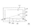
図1は、従来のタッチ・スクリーン・システムの構造を示す図である。米国の特許第4782328号に開示されるタッチ・スクリーン・システム100は、パネル110と、第一光センサー120と、第二光センサー130及びプロセッサー140を備える。パネル110は、長方形のタッチ・スクリーン・エリア112を有する。第一光センサー120及び第二光センサー130は、タッチ・スクリーン・エリア112の一辺112aの両端に対向配置されており、且つ第一光センサー120及び第二光センサー130のセンシング範囲は、タッチ・スクリーン・エリア112を一緒に覆う。また、第一光センサー120及び第二光センサー130は、プロセッサー140に電気接続する。 FIG. 1 is a diagram illustrating the structure of a conventional touch screen system. The
ポインター150がタッチ・スクリーン・エリア112を接触する場合、第一光センサー120及び第二光センサー130は、別々に第一センシング・ライン162及び第二センシング・ライン164に沿ってポインター150をセンシングする。プロセッサー140は、第一センシング・ライン162及び第二センシング・ライン164によってポインター150の位置を計算する。 When the
しかし、従来のタッチ・スクリーン・システム100は、必ず二つの光センサー120、130を必要とするため、従来のタッチ・スクリーン・システム100の生産コストが高い。 However, since the conventional
本発明の目的は、前記問題を解決し、生産コストが低いセンシングシステムを提供することである。 An object of the present invention is to provide a sensing system that solves the above problems and has a low production cost.
本発明に係わるセンシングシステムは、ポインターをセンシングし且つポインターの位置を計算することに用いられる。本発明に係わるセンシングシステムは、パネルと、反射エレメントと、イメージ・センサー及びプロセッサーを備える。パネルは、第一平面及び前記第一平面に位置し且つ順次に連接する第一辺、第二辺、第三辺、第四辺を有する四角形である第一エリアを有する。反射エレメントは、第一辺に配置され、且つ第一平面の上に位置する。反射エレメントの第二平面は、反射面であって、パネルの第一平面に直交し、且つ第一エリアを照り映えて第二エリアを形成する。イメージ・センサーは、第三辺と第四辺が交差する隅に配置され、且つ第一平面の上に位置する。イメージ・センサーのセンシング範囲は、第一エリア及び第二エリアを覆う。プロセッサーは、イメージ・センサーに電気接続する。 The sensing system according to the present invention is used for sensing a pointer and calculating the position of the pointer. The sensing system according to the present invention comprises a panel, a reflective element, an image sensor and a processor. The panel includes a first area that is a quadrilateral having a first side, a second side, a third side, and a fourth side that are located on the first plane and are sequentially connected. The reflective element is disposed on the first side and is located on the first plane. The second plane of the reflective element is a reflective plane that is orthogonal to the first plane of the panel and reflects the first area to form a second area. The image sensor is disposed at a corner where the third side and the fourth side intersect, and is located on the first plane. The sensing range of the image sensor covers the first area and the second area. The processor is electrically connected to the image sensor.
ポインターが第一エリアに接近し、且つポインターが反射エレメントに対向して第一ミラー・イメージを形成して、ポインターと第一ミラー・イメージをイメージ・センサーのセンシング範囲に位置させる時、第一エリアに接近するポインターの一部分及び第二エリアに接近する第一ミラー・イメージの一部分がイメージ・センサーと同じな線に位置しない時、イメージ・センサーは、ポインターと第一ミラー・イメージをセンシングし、プロセッサーは、ポインターの位置を計算する。 When the pointer approaches the first area and the pointer faces the reflective element to form a first mirror image and the pointer and the first mirror image are positioned within the sensing range of the image sensor, the first area The image sensor senses the pointer and the first mirror image when the part of the pointer approaching the first part and the part of the first mirror image approaching the second area are not on the same line as the image sensor. Calculates the position of the pointer.
本発明の実施形態において、イメージ・センサーは、第一センシング・ラインに沿ってポインターをセンシングし、第二センシング・ラインに沿って第一ミラー・イメージをセンシングし、且つプロセッサーは、第一センシング・ラインと第二センシング・ラインによってポインターの位置を計算する。 In an embodiment of the invention, the image sensor senses a pointer along the first sensing line, senses the first mirror image along the second sensing line, and the processor The pointer position is calculated by the line and the second sensing line.
本発明の実施形態において、第一エリアの形状は、長方形である。また、プロセッサーは、第一辺と第三辺との間の第一距離「D1」の情報を有し、且つプロセッサーは、以下のステップによりポインターの位置を計算する。先ず、第一センシング・ラインと第三辺との間の第一角度「A1」を確定する。続いて、第二センシング・ラインと第三辺との間の第二角度「A2」を確定する。続いて、二倍のD1をtanA1とtanA2の和で除算して、ポインターと第四辺との間の第二距離「D2」を計算する。また、センシング・システムは、更に第一線状光源と第二線状光源を備える。 In the embodiment of the present invention, the shape of the first area is a rectangle. Further, the processor has information of the first distance “D1” between the first side and the third side, and the processor calculates the position of the pointer by the following steps. First, the first angle “A1” between the first sensing line and the third side is determined. Subsequently, a second angle “A2” between the second sensing line and the third side is determined. Subsequently, the double D1 is divided by the sum of tanA1 and tanA2 to calculate a second distance “D2” between the pointer and the fourth side. The sensing system further includes a first linear light source and a second linear light source.
第一線状光源は、第二辺に配置されて且つ第一平面に位置し、且つ第一線状光源は、反射エレメントに対向して第二ミラー・イメージを形成する。第二線状光源は、第三辺に配置されて且つ第一平面に位置し、且つ第二線状光源は、反射エレメントに対向して第三ミラー・イメージを形成する。第四辺は、反射エレメントに対向して第四ミラー・イメージを形成する。反射エレメント、第一線状光源、第二線状光源及び第四辺は、第一エリアを巡る。 反射エレメント、第二ミラー・イメージ、
第三ミラー・イメージ及び第四ミラー・イメージは、第二エリアを巡る。第一線状光源、第二ミラー・イメージ及び第三ミラー・イメージは、イメージ・センサーのセンシング範囲内に位置する。The first linear light source is disposed on the second side and is positioned on the first plane, and the first linear light source forms a second mirror image opposite the reflective element. The second linear light source is disposed on the third side and located on the first plane, and the second linear light source forms a third mirror image facing the reflective element. The fourth side forms a fourth mirror image facing the reflective element. The reflective element, the first linear light source, the second linear light source, and the fourth side go around the first area. Reflective element, second mirror image,
The third mirror image and the fourth mirror image go around the second area. The first linear light source, the second mirror image, and the third mirror image are located within the sensing range of the image sensor.
本発明の実施形態において、第一エリアの形状は、長方形ではない四角形である。また、プロセッサーは、隅を経て且つ第一辺に平行する第一イマジナリー・ラインと第一辺との間の第一距離「D3」の情報を有し、且つプロセッサーは、以下のステップによりポインターの位置を計算する。先ず、第一センシング・ラインと第一イマジナリー・ラインとの間の第一角度「A3」を確定する。続いて、第二センシング・ラインと第一イマジナリー・ラインとの間の第二角度「A4」を確定する。続いて、二倍のD3をtanA3とtanA4の和で除算して、隅を経て且つ第一辺に直交する第二イマジナリー・ラインとポインターとの間の第二距離「D4」を計算する。また、センシング・システムは、更に第一線状光源、第二線状光源及び第三線状光源を備える。 In the embodiment of the present invention, the shape of the first area is a quadrangle that is not a rectangle. The processor also has information on the first distance “D3” between the first imaginary line passing through the corner and parallel to the first side and the first side, and the processor performs the following steps: Calculate the position. First, the first angle “A3” between the first sensing line and the first imaginary line is determined. Subsequently, a second angle “A4” between the second sensing line and the first imaginary line is determined. Subsequently, the double D3 is divided by the sum of tanA3 and tanA4 to calculate a second distance “D4” between the second imaginary line passing through the corner and orthogonal to the first side and the pointer. The sensing system further includes a first linear light source, a second linear light source, and a third linear light source.
第一線状光源は、第二辺に配置されて且つ第一平面に位置し、且つ第一線状光源は、反射エレメントに対向して第二ミラー・イメージを形成する。第二線状光源は、第三辺に配置されて且つ第一平面に位置し、且つ第二線状光源は、反射エレメントに対向して第三ミラー・イメージを形成する。第三線状光源は、第四辺に配置されて且つ第一平面に位置し、且つ第三線状光源は、反射エレメントに対向して第四ミラー・イメージを形成する。反射エレメント、第一線状光源、第二線状光源及び第三線状光源は、第一エリアを巡る。反射エレメント、第二ミラー・イメージ、第三ミラー・イメージ及び第四ミラー・イメージは、第二エリアを巡る。第一線状光源、第二ミラー・イメージ、第三ミラー・イメージ及び第四ミラー・イメージは、イメージ・センサーのセンシング範囲に位置する。 The first linear light source is disposed on the second side and is located on the first plane, and the first linear light source forms a second mirror image facing the reflective element. The second linear light source is disposed on the third side and located on the first plane, and the second linear light source forms a third mirror image opposite the reflective element. The third linear light source is disposed on the fourth side and located on the first plane, and the third linear light source forms a fourth mirror image facing the reflective element. The reflective element, the first linear light source, the second linear light source, and the third linear light source travel around the first area. The reflective element, the second mirror image, the third mirror image, and the fourth mirror image travel around the second area. The first linear light source, the second mirror image, the third mirror image, and the fourth mirror image are located in the sensing range of the image sensor.
本発明の実施形態において、ポインターが第一エリアに接近し、且つポインターが反射エレメントに対向して第一ミラー・イメージを形成して、ポインターと第一ミラー・イメージをイメージ・センサーのセンシング範囲に位置させる時、及び第一エリアに接近するポインターの一部分及び第二エリアに接近する第一ミラー・イメージの一部分がイメージ・センサーと同じな線に位置する時、イメージ・センサーは、第三センシング・ラインに沿ってポインターの大きさをセンシングし、プロセッサーは、ポインターと隅との間の第三距離「D5」の長さと第三センシング・ラインに位置するポインターの大きさの対応関係に関する情報を有し、且つプロセッサーは、ポインターの大きさによってポインターの位置を計算する。 In an embodiment of the present invention, the pointer approaches the first area and the pointer faces the reflective element to form a first mirror image, and the pointer and the first mirror image are within the sensing range of the image sensor. When positioned, and when a portion of the pointer approaching the first area and a portion of the first mirror image approaching the second area are located on the same line as the image sensor, the image sensor Sensing the size of the pointer along the line, the processor has information on the correspondence between the length of the third distance “D5” between the pointer and the corner and the size of the pointer located on the third sensing line. The processor calculates the position of the pointer according to the size of the pointer.
本発明の実施形態において、センシングシステムは、パネルの第一平面の上方に配置されて且つ第一エリアの外に位置する第一光源を更に備える。第一光源は、反射エレメントに対向して第二ミラー・イメージを形成する。第一光源と第二ミラー・イメージは、イメージ・センサーのセンシング範囲の外に位置する。ポインターは、光反射表面を有する。第一光源は、不可視光を出し、第一ミラー・イメージは、第一光源がポインターの光反射表面を照り映えることにより形成する。 In an embodiment of the present invention, the sensing system further comprises a first light source disposed above the first plane of the panel and located outside the first area. The first light source forms a second mirror image opposite the reflective element. The first light source and the second mirror image are located outside the sensing range of the image sensor. The pointer has a light reflecting surface. The first light source emits invisible light, and the first mirror image is formed by the first light source shining on the light reflecting surface of the pointer.
本発明の実施形態において、ポインターは、発光装置を有する。第一ミラー・イメージは、発光装置からの光線を介して形成する。 In an embodiment of the present invention, the pointer has a light emitting device. The first mirror image is formed via light rays from the light emitting device.
本発明の実施形態に係るセンシング・システムのプロセッサーは、反射エレメントとイメージ・センサーの配置を介して、ポインターの位置を計算することができる。だから、従来の技術に比べて、本発明の実施形態に係るセンシング・システムは、一つのイメージ・センサーを採用することができ、従って本発明のセンシング・システムの生産コストを下げる。 The processor of the sensing system according to the embodiment of the present invention can calculate the position of the pointer through the arrangement of the reflective element and the image sensor. Therefore, compared with the prior art, the sensing system according to the embodiment of the present invention can employ one image sensor, and thus lower the production cost of the sensing system of the present invention.
本発明を次に図面により詳細に説明する。 The present invention will now be described in detail with reference to the drawings.
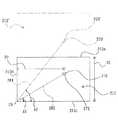
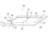
図2は、本発明の第一実施形態に係わるセンシングシステムの構造を示す立体図であって、図3は、図2に示すセンシングシステムが作動する時の平面図である。図2及び図3を参照すると、センシングシステム200は、ポインター270をセンシングし且つポインター270の位置を計算することに用いられる。センシングシステム200は、パネル210と、反射エレメント220と、第一線状光源230と、第二線状光源240と、イメージ・センサー250及びプロセッサー260を備える。パネル210は、例えば、ホワイト・ボード(whiteboard)又はタッチ・スクリーンであって、第一平面214と第一平面214に位置する第一エリア212を有する。第一エリア212の形状は、四角形であって、例えば、長方形であって、且つ第一エリア212は、順次に連接する第一辺212a、第二辺212b、第三辺212c、第四辺212dを有する。 FIG. 2 is a three-dimensional view showing the structure of the sensing system according to the first embodiment of the present invention, and FIG. 3 is a plan view when the sensing system shown in FIG. 2 operates. 2 and 3, the
反射エレメント220は、第一辺212aに配置されており、且つ第一平面214の上に位置する。反射エレメント220の第二平面222は、パネル210の第一平面214に直交する。第二平面222は、反射面であって、且つ第一エリア212を照り映えて第二エリア212’を形成する。反射エレメント220は、例えば、平面ミラーであるが、これに限定されるものではない。第一線状光源230は、第二辺212bに配置されており、且つ第一平面214の上に位置する。第一線状光源230は、反射エレメント220に対向して第二ミラー・イメージ230’を形成する。 The
第二線状光源240は、第三辺212cに配置されており、且つ第一平面214の上に位置する。第二線状光源240は、反射エレメント220に対向して第三ミラー・イメージ240’を形成する。第四辺212dは、反射エレメント220に対向して第四ミラー・イメージ212d’を形成する。反射エレメント220、第一線状光源230、第二線状光源240及び第四辺212dは、第一エリア212を巡る。 反射エレメント220、第二ミラー・イメージ230’、
第三ミラー・イメージ240’及び第四ミラー・イメージ212d’は、第二エリア212’を巡る。The second linear
The
イメージ・センサー250は、第三辺212cと第四辺212dが交差する隅C1に配置されており、且つ第一平面214の上に位置する。イメージ・センサー250のセンシング範囲は、第一エリア212及び第二エリア212’を覆う。第一線状光源230、第二ミラー・イメージ230’及び第三ミラー・イメージ240’は、イメージ・センサー250のセンシング範囲内に位置する。また、プロセッサー260は、イメージ・センサー250に電気接続する。 The
以下、本実施形態に係るセンシングシステム200の作動方式に対して説明する。図4は、図3に示すプロセッサーがポインターの位置を計算することを示す図であって、図5は、図3に示すイメージ・センサーのイメージ・センシング・ウィンドーを示す図である。図3、図4及び図5を参照すると、ポインター270(図2を参照してください)が第一エリア212に接近し、且つポインター270が反射エレメント220に対向して第一ミラー・イメージ270’を形成して、ポインター270と第一ミラー・イメージ270’をイメージ・センサー250のセンシング範囲内に位置させる時、第一エリア212に接近するポインター270の一部分及び第二エリア212’に接近する第一ミラー・イメージ270’の一部分がイメージ・センサー250と同じな線に位置しない時、イメージ・センサー250は、ポインター270と第一ミラー・イメージ270’をセンシングし、且つプロセッサー260は、ポインター270の位置を計算する。本実施形態のイメージ・センサー250は、第一センシング・ライン282に沿ってポインター270をセンシングし、第二センシング・ライン284に沿って第一ミラー・イメージ270’をセンシングし、且つプロセッサー260は、第一センシング・ライン282と第二センシング・ライン284によってポインター270の位置を計算する。 Hereinafter, an operation method of the
ここで説明しなければならないことは、本実施形態において、第一エリア212に接近するポインター270の一部分は、ポインター270の先端272(図2を参照してください)であって、第二エリア212’に接近する第一ミラー・イメージ270’の一部分は、第一ミラー・イメージ270’の先端272’である。 What has to be explained here is that in this embodiment, the portion of the
詳しく説明すると、本実施形態において、イメージ・センサー250は、イメージ・センシング・ウィンドー252を有する。ポインター270が第一エリア212に接近しなかった時、第一線状光源230、第二ミラー・イメージ230’及び第三ミラー・イメージ240’からの光線は、イメージ・センシング・ウィンドー252に高い輝度のブライト・ゾーン(bright zone)254を形成し、これは主要なセンシング・ゾーン(sensing zone)である。ポインター270が第一エリア212に接近する時、イメージ・センサー250は、第一センシング・ライン282に沿ってポインター270をセンシングし、イメージ・センシング・ウィンドー252の上のブライト・ゾーン254に第一暗線(obscure line)252aが出現し、且つイメージ・センサー250から第一電気信号を出力する。プロセッサー260は、第一電気信号を受信し、且つイメージ・センシング・ウィンドー252の上の第一暗線252aの位置によって、第一センシング・ライン282と第三辺212cとの間の第一角度A1を確定する。換言すると、プロセッサー260は、内蔵方式を介して、センシング・ラインと第三辺212cとの間の角度とイメージ・センシング・ウィンドー252の上の暗線の位置の対応関係に関する情報を有し、第一角度A1を確定する工作を執行させる。 More specifically, in the present embodiment, the
同じ道理で、イメージ・センサー250は、第二センシング・ライン284に沿って第一ミラー・イメージ270’をセンシングし、メージ・センシング・ウィンドー252の上のブライト・ゾーン254に第二暗線252bが出現し、且つイメージ・センサー250から第二電気信号を出力する。プロセッサー260は、第二電気信号を受信し、且つイメージ・センシング・ウィンドー252の上の第二暗線252bの位置によって、第二センシング・ライン284と第三辺212cとの間の第二角度A2を確定する。ここで説明しなければならないことは、第一線状光源230と第二線状光源240の輝度が強ければ強いほど、イメージ・センシング・ウィンドー252の上の第一暗線252aと第二暗線252bが明らかになる。 In the same reason, the
また、プロセッサー260は、内蔵方式を介して、第一辺212aと第三辺212cとの間の第一距離D1の情報を有する。本実施形態において、第三辺212cは、直角座標系(cartesian coordinate system)のX軸として、第四辺212dは、直角座標系のY軸として、且つ隅C1の座標は(0,0)である。ポインター270のX座標は、ポインター270と第四辺212dとの間の第二距離D2であって、且つポインター270と第一ミラー・イメージ270’の中点が第一辺212aに位置するため、D1は、(D2・tanA1+D2・tanA2)/2である。だから、プロセッサー260は、二倍のD1をtanA1とtanA2の和で除算して、ポインター270と第四辺212dとの間の第二距離D2を計算する。換言すると、ポインター270の座標(D2,D2・tanA1)は、上述の計算方式から計算することができる。ここで説明しなければならないことは、直角座標系でポインター270の座標を計算する方式は、ただ例として、設計者は、設計需要に基づいて他の座標システムを採用してポインターの座標を計算することができ、本発明は、これに限定されるものではない。 Further, the
本実施形態に係るセンシング・システム200のプロセッサー260は、反射エレメント220とイメージ・センサー250の配置を介して、ポインター270の位置を計算する。だから、従来の技術に比べて、本実施形態に係るセンシング・システム200は、一つのイメージ・センサー250を採用することができ、従ってセンシング・システム200の生産コストを下げる。 The
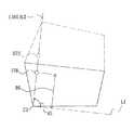
図6は、本発明の第二実施形態に係るセンシングシステムが作動する時の平面図である。図7は、図6に示すプロセッサーがポインターの位置を計算することを示す図である。図6及び図7を参照すると、本実施形態に係るセンシングシステム300が第一実施形態に係るセンシングシステム200に比べて異なったことは、センシングシステム300は、第三線状光源390を更に備え、且つパネル310の第一平面314に位置する第一エリア312の形状は、長方形ではない四角形である。 FIG. 6 is a plan view when the sensing system according to the second embodiment of the present invention operates. FIG. 7 is a diagram illustrating that the processor illustrated in FIG. 6 calculates the position of the pointer. 6 and 7, the
第三線状光源390は、第一エリア312の第四辺312dに配置されており、且つ第三線状光源390は、反射エレメント320に対向して第四ミラー・イメージ390’を形成する。反射エレメント320(第一エリア312の第一辺312a配置する)、第一線状光源330(第一エリア312の第二辺312b配置する)、第二線状光源340(第一エリア312の第三辺312c配置する)及び第三線状光源390は、第一エリア312を巡る。 The third linear
反射エレメント320、第一線状光源330が反射エレメント320に対向して形成した第二ミラー・イメージ330’、 第二線状光源340が反射エレメント320に対向して形成した第三ミラー・イメージ340’及び第四ミラー・イメージ390’は、第二エリア312’を巡る。また、イメージ・センサー350は、第三辺312cと第四辺312dが交差する隅C2に配置されており、且つイメージ・センサー350のセンシング範囲は、第一エリア312及び第二エリア312’を覆う。第一線状光源330、第二ミラー・イメージ330’、第三ミラー・イメージ340’及び第四ミラー・イメージ390’は、イメージ・センサー350のセンシング範囲内に位置する。また、ポインター370は、反射エレメント320に対向して第一ミラー・イメージ370’を形成する。 A
以下、本実施形態に係るセンシングシステム300の作動方式に対して説明する。本実施形態において、隅C2を経て且つ第一辺312aに平行する第一イマジナリー・ラインL1を直角座標系のX軸として、隅C2を経て且つ第一辺312aに直交する第二イマジナリー・ラインL2を直角座標系のY軸として、且つ隅C2の座標は、(0,0)である。プロセッサー360は、内蔵方式を介して、第一イマジナリー・ラインL1と第一辺312aとの間の第一距離D3の情報を有する。 Hereinafter, an operation method of the
ポインター370が第一エリア312に接近し、且つポインター370が反射エレメント320に対向して第一ミラー・イメージ370’を形成して、ポインター370と第一ミラー・イメージ370’をイメージ・センサー350のセンシング範囲内に位置させる時、第一エリア312に接近するポインター370の一部分及び第二エリア312’に接近する第一ミラー・イメージ370’の一部分がイメージ・センサー350と同じな線に位置しない時、イメージ・センサー350は、先ず第一センシング・ライン382に沿ってポインター370をセンシングし、第二センシング・ライン384に沿って第一ミラー・イメージ370’をセンシングし、続いてプロセッサー360は、第一センシング・ライン382と第二センシング・ライン384によって、別々に第一センシング・ライン382と第一イマジナリー・ラインL1との間の第一角度A3及び第二センシング・ライン384と第一イマジナリー・ラインL1との間の第二角度A4を確定する。続いて、プロセッサー360は、二倍のD3をtanA3とtanA4の和で除算して、第二イマジナリー・ラインL2とポインター370との間の第二距離D4を計算する。だから、ポインター370の座標(D4,D4・tanA3)は、上述の計算方式から計算することができる。 The
ここで説明しなければならないことは、本実施形態に係るイメージ・センサー350のセンシング方式とプロセッサー360の角度確定方式は、第一実施形態の叙述を参考することができ、ここで詳しく説明しない。 What has to be described here is that the sensing method of the
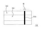
図8は、図6に示すプロセッサーがポインターの位置を計算することを示す他の図であって、図9は、図6に示すイメージ・センサーのイメージ・センシング・ウィンドーを示す図である。図6、図8及び図9を参照すると、本実施形態において、ポインター370が第一エリア312に接近しなかった時、第一線状光源330、第二ミラー・イメージ330’、第三ミラー・イメージ340’及び第四ミラー・イメージ390’からの光線は、イメージ・センシング・ウィンドー352(図6を参照してください)に高い輝度のブライト・ゾーン(bright zone)354を形成し、これは主要なセンシング・ゾーン(sensing zone)である。第一エリア312に接近するポインター370の一部分及び第二エリア312’に接近する第一ミラー・イメージ370’の一部分がイメージ・センサー350と同じな線に位置する時、イメージ・センサー350は、第三センシング・ライン386(第二イマジナリー・ラインL2である)に沿ってポインター370の大きさをセンシングする。ここで説明しなければならないことは、本実施形態のプロセッサー360は、内蔵方式を介して、ポインター370と隅C2との間の第三距離D5の長さと第三センシング・ライン386に位置するポインター370の大きさの対応関係に関する情報を有し、且つプロセッサー360は、ポインター370の大きさによってポインター370の位置を計算する。 FIG. 8 is another diagram showing that the processor shown in FIG. 6 calculates the position of the pointer, and FIG. 9 is a diagram showing an image sensing window of the image sensor shown in FIG. Referring to FIGS. 6, 8 and 9, in this embodiment, when the
換言すると、ポインター370がイメージ・センサー350のイメージ・センシング・ウィンドー352に接近すればするほど(即ち第三距離D5が小さければ小さいほど)、イメージ・センシング・ウィンドー352の上のブライト・ゾーン354に出現する第三暗線352cの幅W1が大きくなる。幅W1の大きさと第三距離D5の長さの対応関係は、予めプロセッサー360に内蔵することができる。だから、ポインター370、第一ミラー・イメージ370’及びイメージ・センサー350が同じな線に位置する時、プロセッサー360は、ポインター370の大きさによって、対応する第三距離D5を計算する。 In other words, the closer the
本実施形態において、プロセッサー360は、内蔵方式を介して、第三センシング・ライン386と第一イマジナリー・ラインL1との間の第三角度A5の情報を有するため、ポインター370の座標(D5・cosA5,D5・sinA5)を求めることができる。本実施形態において、第三角度A5は、90度である。In the present embodiment, since the
図10は、本発明の第三実施形態に係るセンシングシステムの構造を示す立体図である。図2及び図10を参照すると、センシングシステム400がセンシングシステム200に比べて異なったことは、センシングシステム400は、第一線状光源230と第二線状光源240の配置を省略する。センシングシステム400は、パネル410の第一平面414の上方に配置され、且つ第一エリア412の外に位置する第一光源430を備える。第一光源430は、反射エレメント420に対向して第二ミラー・イメージ430’を形成する。第一光源430と第二ミラー・イメージ430’は、イメージ・センサー450のセンシング範囲の外に位置する。ポインター470は、光反射表面472を有し、光反射表面472の光反射材料は、例えばヨーロッパ規則EN471の規格に符合するが、これに限定されるものではない。 FIG. 10 is a three-dimensional view showing the structure of the sensing system according to the third embodiment of the present invention. Referring to FIGS. 2 and 10, the
第一光源430は、不可視光を出し、例えば、波長が約940nmである赤外光である。ポインター470が反射エレメント420に対向して形成した第一ミラー・イメージ(図しせず)は、第一光源430がポインター470の光反射表面472を照り映えることにより形成する。イメージ・センサー450は、イメージ・センシング・ウィンドー452の前に配置されるフィルター456を有することができる。ポインター470は、不可視光をフィルター456に反射することができ、フィルター456は、他の光線を濾過して、イメージ・センシング・ウィンドー452がポインター470から反射する不可視光を受信することにする。また、イメージ・センサー450は、ポインター470の第一ミラー・イメージ(図しせず)をセンシングすることができる。 The first
ここで説明しなければならないことは、第一エリア412は、長方形ではない四角形であることができるが、図面で表示しなかった。 What has to be explained here is that the
図11は、本発明の第四実施形態に係るセンシングシステムの構造を示す立体図である。図2及び図11を参照すると、センシングシステム500がセンシングシステム200に比べて異なったことは、センシングシステム500は、第一線状光源230と第二線状光源240の配置を省略する。ポインター570は、発光装置572を有し、且つ第一ミラー・イメージ(図しせず)は、発光装置572からの光線を介して形成する。イメージ・センサー550は、ポインター570及びポインター570が反射エレメント520に対向して形成した第一ミラー・イメージ(図しせず)をセンシングすることができる。 FIG. 11 is a three-dimensional view showing the structure of the sensing system according to the fourth embodiment of the present invention. Referring to FIGS. 2 and 11, the
ここで説明しなければならないことは、第一エリア512は、長方形ではない四角形であることができるが、図面で表示しなかった。 What has to be explained here is that the
以上本発明を実施例に基づいて具体的に説明したが、本発明は、上述の実施例に限定されるものではなく、その要旨を逸脱しない範囲において、種種変更可能であることは勿論であって、本発明の保護範囲は、以下の特許請求の範囲から決まる。 The present invention has been specifically described above based on the embodiments. However, the present invention is not limited to the above-described embodiments, and it goes without saying that various modifications can be made without departing from the scope of the present invention. Thus, the protection scope of the present invention is determined from the following claims.
100 タッチ・スクリーン・システム
110、210、310、410 パネル
112 タッチ・スクリーン・エリア
112a 一辺
120 第一光センサー
130 第二光センサー
140、260、360 プロセッサー
150、270、370、470、570 ポインター
162、282、382 第一センシング・ライン
164、284、384 第二センシング・ライン
200、300、400、500 センシングシステム
212、312、412、512 第一エリア
212’、 312’ 第二エリア
212a、312a、412a 第一辺
212b、312b、412b 第二辺
212c、312c、412c 第三辺
212d、312d 第四辺
212d’、390’ 第四ミラー・イメージ
214、314、414 第一平面
220、320、420、520 反射エレメント
222 第二平面
230、330 第一線状光源
230’、330’、430’ 第二ミラー・イメージ
240、340 第二線状光源
240’、 340’ 第三ミラー・イメージ
250、350、450、550 イメージ・センサー
252、352、452 イメージ・センシング・ウィンドー
252a 第一暗線
252b 第二暗線
254、354 ブライト・ゾーン
270’、 370’ 第一ミラー・イメージ
272、272’ 先端
352c 第三暗線
386 第三センシング・ライン
390 第三線状光源
430 第一光源
456 フィルター
472 光反射表面
572 発光装置
A1、A3 第一角度
A2、A4 第二角度
A5 第三角度
C1、C2 隅
D1、D3 第一距離
D2、D4 第二距離
D5 第三距離
L1 第一イマジナリー・ライン
L2 第二イマジナリー・ライン
W1 幅100
230 ′, 330 ′, 430 ′
272, 272 ′
Claims (11)
Translated fromJapanese第一平面及び前記第一平面に位置し且つ順次に連接する第一辺、第二辺、第三辺、第四辺を有する四角形である第一エリアを有するパネルと、
前記第一辺に配置され、且つ前記第一平面の上に位置し、その第二平面は、反射面であって前記第一平面に直交し、且つ前記第一エリアを照り映えて第二エリアを形成する反射エレメントと、
前記第三辺と前記第四辺が交差する隅に配置され、且つ前記第一平面の上に位置し、そのセンシング範囲は、前記第一エリア及び前記第二エリアを覆うイメージ・センサーと、
前記イメージ・センサーに電気接続するプロセッサーとを備え、前記ポインターが前記第一エリアに接近し、且つ前記ポインターが前記反射エレメントに対向して第一ミラー・イメージを形成して、前記ポインターと前記第一ミラー・イメージを前記イメージ・センサーのセンシング範囲に位置させる時、前記第一エリアに接近する前記ポインターの一部分及び前記第二エリアに接近する前記第一ミラー・イメージの一部分が前記イメージ・センサーと同じな線に位置しない時、前記イメージ・センサーは、前記ポインターと前記第一ミラー・イメージをセンシングし、前記プロセッサーは、前記ポインターの位置を計算することを特徴とするセンシングシステム。A sensing system used to sense a pointer and calculate the position of the pointer,
A panel having a first area that is a quadrilateral having a first plane and a first side, a second side, a third side, and a fourth side that are located in the first plane and sequentially connected;
The second area is disposed on the first side and located on the first plane, and the second plane is a reflecting surface that is orthogonal to the first plane and reflects the first area. A reflective element forming
The third side and the fourth side are arranged at a corner where the fourth side intersects and are located on the first plane, and the sensing range thereof is an image sensor that covers the first area and the second area;
A processor electrically connected to the image sensor, wherein the pointer approaches the first area and the pointer faces the reflective element to form a first mirror image, the pointer and the first When a mirror image is positioned within the sensing range of the image sensor, a portion of the pointer approaching the first area and a portion of the first mirror image approaching the second area are the image sensor. The sensing system senses the pointer and the first mirror image when not located on the same line, and the processor calculates the position of the pointer.
Applications Claiming Priority (1)
| Application Number | Priority Date | Filing Date | Title |
|---|---|---|---|
| TW97126033 | 2008-07-10 |
Related Child Applications (1)
| Application Number | Title | Priority Date | Filing Date |
|---|---|---|---|
| JP2011049089ADivisionJP2011117977A (en) | 2008-07-10 | 2011-03-07 | Sensing system |
Publications (1)
| Publication Number | Publication Date |
|---|---|
| JP2010019822Atrue JP2010019822A (en) | 2010-01-28 |
Family
ID=41505924
Family Applications (3)
| Application Number | Title | Priority Date | Filing Date |
|---|---|---|---|
| JP2008211019APendingJP2010019822A (en) | 2008-07-10 | 2008-08-19 | Sensing system |
| JP2011049089APendingJP2011117977A (en) | 2008-07-10 | 2011-03-07 | Sensing system |
| JP2013099802APendingJP2013178807A (en) | 2008-07-10 | 2013-05-10 | Sensing system |
Family Applications After (2)
| Application Number | Title | Priority Date | Filing Date |
|---|---|---|---|
| JP2011049089APendingJP2011117977A (en) | 2008-07-10 | 2011-03-07 | Sensing system |
| JP2013099802APendingJP2013178807A (en) | 2008-07-10 | 2013-05-10 | Sensing system |
Country Status (3)
| Country | Link |
|---|---|
| US (1) | US7689381B2 (en) |
| JP (3) | JP2010019822A (en) |
| KR (1) | KR100994526B1 (en) |
Families Citing this family (22)
| Publication number | Priority date | Publication date | Assignee | Title |
|---|---|---|---|---|
| US8427453B2 (en)* | 2008-07-10 | 2013-04-23 | Pixart Imaging Inc. | Optical sensing system |
| US8305363B2 (en)* | 2008-10-10 | 2012-11-06 | Pixart Imaging | Sensing system and locating method thereof |
| US8368668B2 (en) | 2009-06-30 | 2013-02-05 | Pixart Imaging Inc. | Displacement detection system of an optical touch panel and method thereof |
| TWI413925B (en)* | 2010-06-11 | 2013-11-01 | Pixart Imaging Inc | Optical touch system, apparatus and method for calculating the position of an object |
| CN102314258B (en)* | 2010-07-01 | 2013-10-23 | 原相科技股份有限公司 | Optical touch system, object position calculation device and object position calculation method |
| CN102402345A (en)* | 2010-09-17 | 2012-04-04 | 原相科技股份有限公司 | Optical touch device and touch sensing method thereof |
| TWI441060B (en) | 2011-04-14 | 2014-06-11 | Pixart Imaging Inc | Image processing method for optical touch system |
| TWI480784B (en) | 2011-06-21 | 2015-04-11 | Pixart Imaging Inc | Optical touch panel system and image processing method thereof |
| US8860695B2 (en)* | 2011-08-05 | 2014-10-14 | Pixart Imaging Inc. | Optical touch system and electronic apparatus including the same |
| US9229578B2 (en) | 2011-08-05 | 2016-01-05 | Pixart Imaging Inc. | Image sensor and optical touch system including the same |
| TWI460636B (en) | 2011-09-07 | 2014-11-11 | Pixart Imaging Inc | Optical touch panel system and positioning method thereof |
| TWI448918B (en)* | 2011-09-09 | 2014-08-11 | Pixart Imaging Inc | Optical panel touch system |
| US8884904B2 (en)* | 2011-10-13 | 2014-11-11 | PixArt Imaging Incorporation, R.O.C. | Touch panel apparatus, system and operation method thereof |
| TWI463375B (en)* | 2011-10-19 | 2014-12-01 | Pixart Imaging Inc | Optical touch system, optical sensing module and operating method thereof |
| CN103076925B (en)* | 2011-10-26 | 2016-07-06 | 原相科技股份有限公司 | Optical touch control system, optical sensing module and How It Works thereof |
| US10281445B2 (en)* | 2011-11-30 | 2019-05-07 | Shimadzu Corporation | Headspace sampler |
| TWI470475B (en) | 2012-04-17 | 2015-01-21 | Pixart Imaging Inc | Electronic system |
| TWI684031B (en) | 2012-07-16 | 2020-02-01 | 美商唯亞威方案公司 | Optical filter and sensor system |
| US9489085B2 (en) | 2012-10-08 | 2016-11-08 | PixArt Imaging Incorporation, R.O.C. | Optical touch panel system and positioning method thereof |
| US9213448B2 (en) | 2012-11-29 | 2015-12-15 | Pixart Imaging Inc. | Positioning module, optical touch system and method of calculating a coordinate of a touch medium |
| TWI475448B (en)* | 2012-11-29 | 2015-03-01 | Pixart Imaging Inc | Positioning module, optical touch system and method of calculating a coordinate of a stylus |
| US12106505B2 (en)* | 2020-09-02 | 2024-10-01 | International Business Machines Corporation | Reflection-based distance perception |
Citations (3)
| Publication number | Priority date | Publication date | Assignee | Title |
|---|---|---|---|---|
| JPS59211128A (en)* | 1983-05-09 | 1984-11-29 | ウェルスーガードナー エレクトロニクス コーポレイション | optical position sensing device |
| JPH113170A (en)* | 1997-06-13 | 1999-01-06 | Wacom Co Ltd | Optical digitizer |
| JP2005025415A (en)* | 2003-06-30 | 2005-01-27 | Sony Corp | Position detector |
Family Cites Families (12)
| Publication number | Priority date | Publication date | Assignee | Title |
|---|---|---|---|---|
| DE2217536C2 (en)* | 1972-04-12 | 1974-05-09 | Carl Schenck Maschinenfabrik Gmbh, 6100 Darmstadt | Arrangement for regulating a dynamic test system, in particular for a hydraulically driven one |
| US4507557A (en) | 1983-04-01 | 1985-03-26 | Siemens Corporate Research & Support, Inc. | Non-contact X,Y digitizer using two dynamic ram imagers |
| US4782328A (en) | 1986-10-02 | 1988-11-01 | Product Development Services, Incorporated | Ambient-light-responsive touch screen data input method and system |
| JPH0736603A (en)* | 1993-07-16 | 1995-02-07 | Wacom Co Ltd | Two-dimensional position detector |
| JPH0883415A (en)* | 1994-07-15 | 1996-03-26 | Sony Corp | Signal recording and/or reproducing device, signal recording and/or reproducing method and recording medium |
| DE19539955A1 (en) | 1995-10-26 | 1997-04-30 | Sick Ag | Optical detection device |
| US6036189A (en)* | 1998-05-19 | 2000-03-14 | Williams Electronics Games, Inc. | Game with viewing panel having variable optical characteristics for producing virtual images |
| US6803906B1 (en) | 2000-07-05 | 2004-10-12 | Smart Technologies, Inc. | Passive touch system and method of detecting user input |
| US7442914B2 (en)* | 2003-09-12 | 2008-10-28 | Flatfrog Laboratories Ab | System and method of determining a position of a radiation emitting element |
| US20090090569A1 (en)* | 2005-10-13 | 2009-04-09 | Cho-Yi Lin | Sensing System |
| US20070165007A1 (en)* | 2006-01-13 | 2007-07-19 | Gerald Morrison | Interactive input system |
| JP5025552B2 (en)* | 2008-04-16 | 2012-09-12 | キヤノン株式会社 | Touch panel |
- 2008
- 2008-08-19JPJP2008211019Apatent/JP2010019822A/enactivePending
- 2008-09-29KRKR1020080095265Apatent/KR100994526B1/ennot_activeExpired - Fee Related
- 2008-10-10USUS12/249,222patent/US7689381B2/ennot_activeExpired - Fee Related
- 2011
- 2011-03-07JPJP2011049089Apatent/JP2011117977A/enactivePending
- 2013
- 2013-05-10JPJP2013099802Apatent/JP2013178807A/enactivePending
Patent Citations (3)
| Publication number | Priority date | Publication date | Assignee | Title |
|---|---|---|---|---|
| JPS59211128A (en)* | 1983-05-09 | 1984-11-29 | ウェルスーガードナー エレクトロニクス コーポレイション | optical position sensing device |
| JPH113170A (en)* | 1997-06-13 | 1999-01-06 | Wacom Co Ltd | Optical digitizer |
| JP2005025415A (en)* | 2003-06-30 | 2005-01-27 | Sony Corp | Position detector |
Also Published As
| Publication number | Publication date |
|---|---|
| JP2011117977A (en) | 2011-06-16 |
| KR100994526B1 (en) | 2010-11-15 |
| KR20100007673A (en) | 2010-01-22 |
| US20100010773A1 (en) | 2010-01-14 |
| US7689381B2 (en) | 2010-03-30 |
| JP2013178807A (en) | 2013-09-09 |
Similar Documents
| Publication | Publication Date | Title |
|---|---|---|
| JP2010019822A (en) | Sensing system | |
| US20090090569A1 (en) | Sensing System | |
| KR101123932B1 (en) | Optical touch system and method | |
| TWI441047B (en) | Sensing system | |
| TWI430151B (en) | Touch device and touch method thereof | |
| US9471180B2 (en) | Optical touch panel system, optical apparatus and positioning method thereof | |
| CN101644975B (en) | Sensing system | |
| JP5351218B2 (en) | Light guide and optical touch panel using the same | |
| US8232511B2 (en) | Sensing system adapted to sense a pointer and calculate a location of the pointer | |
| US8912482B2 (en) | Position determining device and method for objects on a touch device having a stripped L-shaped reflecting mirror and a stripped retroreflector | |
| TWI451310B (en) | Optical touch module and light source module thereof | |
| TWI587196B (en) | Optical touch system and optical detecting method for touch position | |
| TWI705366B (en) | Optical touch device and optical touch method | |
| US20140267173A1 (en) | Touch control apparatus and associated selection method | |
| CN101739176A (en) | Sensing system | |
| CN102902420B (en) | Sensing system | |
| TWI520037B (en) | Optical touch panel system, optical apparatus and positioning method thereof | |
| TWI460636B (en) | Optical touch panel system and positioning method thereof | |
| JP2010108493A (en) | Sensor system | |
| CN102479001B (en) | Touch device and touch method thereof | |
| TWI423095B (en) | Object-detecting system and method by use of non-coincident fields of light |
Legal Events
| Date | Code | Title | Description |
|---|---|---|---|
| A977 | Report on retrieval | Free format text:JAPANESE INTERMEDIATE CODE: A971007 Effective date:20101201 | |
| A131 | Notification of reasons for refusal | Free format text:JAPANESE INTERMEDIATE CODE: A131 Effective date:20101207 | |
| A521 | Written amendment | Free format text:JAPANESE INTERMEDIATE CODE: A523 Effective date:20110307 | |
| A131 | Notification of reasons for refusal | Free format text:JAPANESE INTERMEDIATE CODE: A131 Effective date:20110329 | |
| A521 | Written amendment | Free format text:JAPANESE INTERMEDIATE CODE: A523 Effective date:20110628 | |
| A02 | Decision of refusal | Free format text:JAPANESE INTERMEDIATE CODE: A02 Effective date:20110726 |