Movatterモバイル変換


[0]ホーム

URL:


JP2010016977A - Charging system and power supply device - Google Patents

Charging system and power supply device
Download PDF

Info

Publication number
JP2010016977A
JP2010016977AJP2008174475AJP2008174475AJP2010016977AJP 2010016977 AJP2010016977 AJP 2010016977AJP 2008174475 AJP2008174475 AJP 2008174475AJP 2008174475 AJP2008174475 AJP 2008174475AJP 2010016977 AJP2010016977 AJP 2010016977A
Authority
JP
Japan
Prior art keywords
energy
charging system
unit
electronic cassette
cradle
Prior art date
Legal status (The legal status is an assumption and is not a legal conclusion. Google has not performed a legal analysis and makes no representation as to the accuracy of the status listed.)
Abandoned
Application number
JP2008174475A
Other languages
Japanese (ja)
Inventor
Hideto Bettoyashiki
豪人 別当屋敷
Naoyuki Nishino
直行 西納
Yasuyoshi Ota
恭義 大田
Keiji Tsubota
圭司 坪田
Current Assignee (The listed assignees may be inaccurate. Google has not performed a legal analysis and makes no representation or warranty as to the accuracy of the list.)
Fujifilm Corp
Original Assignee
Fujifilm Corp
Priority date (The priority date is an assumption and is not a legal conclusion. Google has not performed a legal analysis and makes no representation as to the accuracy of the date listed.)
Filing date
Publication date
Application filed by Fujifilm CorpfiledCriticalFujifilm Corp
Priority to JP2008174475ApriorityCriticalpatent/JP2010016977A/en
Publication of JP2010016977ApublicationCriticalpatent/JP2010016977A/en
Abandonedlegal-statusCriticalCurrent

Links

Images

Landscapes

Abstract

Translated fromJapanese

【課題】電子機器を容易に所定の充電位置に位置決めすることができる充電システム及び給電装置を提供する。
【解決手段】電子カセッテ12が、外部からエネルギーを受給するコイルユニット38が収納された把持部18、及びコイルユニット38によって受給されたエネルギーが供給されて充電される二次電池36を有し、クレードル14が、コイルユニット38にエネルギーを供給する電磁石44が収納されると共に、把持部18が掛けられた際の当該把持部18との接触面に対応する形状の凹部24が形成された突出部22を有する。
【選択図】図4
Provided are a charging system and a power feeding device capable of easily positioning an electronic device at a predetermined charging position.
An electronic cassette has a gripping part in which a coil unit that receives energy from the outside is housed, and a secondary battery that is charged with the energy received by the coil unit. The cradle 14 houses an electromagnet 44 that supplies energy to the coil unit 38, and has a protrusion 24 formed with a recess 24 having a shape corresponding to a contact surface with the grip 18 when the grip 18 is hooked. 22.
[Selection] Figure 4

Description

Translated fromJapanese

本発明は、充電システム及び給電装置に係り、特に、二次電池やキャパシタなどの蓄電手段を備えた電子機器と、当該電子機器に前記蓄電手段を充電するためのエネルギーを供給する給電装置と、を備えた充電システム、及び前記給電装置に関する。  The present invention relates to a charging system and a power supply device, and in particular, an electronic device provided with power storage means such as a secondary battery and a capacitor, and a power supply device that supplies energy for charging the power storage means to the electronic device, And a power supply apparatus.

近年、TFT(Thin Film Transistor)アクティブマトリクス基板上にX線感応層を配置し、X線を直接デジタルデータに変換できるFPD(Flat Panel Detector)が実用化されており、このFPD等を用いて照射された放射線により表わされる放射線画像を示す画像情報を生成し、生成した画像情報を記憶する可搬型放射線画像変換装置(以下、「電子カセッテ」ともいう。)が実用化されている。  In recent years, an FPD (Flat Panel Detector) has been put into practical use, in which an X-ray sensitive layer is arranged on a TFT (Thin Film Transistor) active matrix substrate, and X-rays can be directly converted into digital data. 2. Description of the Related Art A portable radiographic image conversion apparatus (hereinafter also referred to as “electronic cassette”) that generates image information indicating a radiographic image represented by the emitted radiation and stores the generated image information has been put into practical use.

電子カセッテは、一般に、携帯性を向上させるために二次電池を備えているが、電子カセッテを含む携帯型の装置に設けられた二次電池に充電用の電力を供給することに関する技術としては、以下の各特許文献に開示された技術が知られている。  In general, an electronic cassette is provided with a secondary battery to improve portability. However, as a technique related to supplying electric power for charging to a secondary battery provided in a portable device including the electronic cassette, Techniques disclosed in the following patent documents are known.

すなわち、特許文献1には、電子カセッテに設けられた二次電池に充電用の電力を供給する床置き型の給電装置が開示されている。また、特許文献2には、電子機器に設けられた二次電池に充電用の電力を供給するフック型の給電装置が開示されている。更に、特許文献3には、デジタルカメラに設けられた二次電池に充電用の電力を供給するにあたり、三脚穴を利用して正確にデジタルカメラの位置決めを行う技術が開示されている。
特開2002−248095号公報特開2005−303390号公報特開2007−28302号公報
That is,Patent Document 1 discloses a floor-mounted power supply device that supplies power for charging to a secondary battery provided in an electronic cassette. Patent Document 2 discloses a hook-type power feeding device that supplies power for charging to a secondary battery provided in an electronic device. Furthermore, Patent Document 3 discloses a technique for accurately positioning a digital camera using a tripod hole when supplying charging power to a secondary battery provided in the digital camera.
Japanese Patent Laid-Open No. 2002-248095 JP 2005-303390 A JP 2007-28302 A

しかしながら、特許文献1の技術では、給電装置を床に置くことになるので、衛生面の観点から好ましくない、という問題点があった。また、清掃等の各種作業の邪魔になる、という問題点もあった。  However, the technique ofPatent Document 1 has a problem that it is not preferable from the viewpoint of hygiene because the power feeding device is placed on the floor. Also, there is a problem that it interferes with various operations such as cleaning.

また、特許文献2の技術では、給電装置を床に置かずに電子機器に電力を供給することはできるものの、フック上において電子機器の位置が安定しないため、電力を安定して供給することができない、という問題点があった。  In the technique of Patent Document 2, although electric power can be supplied to the electronic device without placing the power supply device on the floor, the position of the electronic device is not stable on the hook, so that electric power can be supplied stably. There was a problem that it was not possible.

更に、特許文献3の技術では、電子機器の位置を安定させて充電を行うことはできるものの、電子カセッテのように比較的重い電子機器に設けられた二次電池に充電用の電力を供給する場合には位置決めを行うことが困難である、という問題点があった。  Furthermore, in the technique of Patent Document 3, charging can be performed while stabilizing the position of the electronic device, but charging power is supplied to a secondary battery provided in a relatively heavy electronic device such as an electronic cassette. In some cases, it is difficult to perform positioning.

本発明は上記問題点を解決するために成されたものであり、電子機器を容易に所定の充電位置に位置決めすることができる充電システム及び給電装置を提供することを目的とする。  The present invention has been made to solve the above-described problems, and an object of the present invention is to provide a charging system and a power feeding apparatus that can easily position an electronic device at a predetermined charging position.

上記目的を達成するために、請求項1に記載の充電システムは、外部からエネルギーを受給する受給手段が収納された把持部、及び前記受給手段によって受給されたエネルギーが供給されて充電される蓄電手段を有する電子機器と、前記受給手段にエネルギーを供給する供給手段が収納されると共に、前記把持部が掛けられた際の当該把持部との接触面に対応する形状の凹部が形成された突出部を有する給電装置と、を含んでいる。  In order to achieve the above object, the charging system according toclaim 1 includes a gripping part in which a receiving means for receiving energy from the outside is stored, and an electricity storage that is charged by being supplied with the energy received by the receiving means. An electronic device having a means and a supply means for supplying energy to the receiving means are housed, and a protrusion formed with a recess corresponding to the contact surface with the gripping part when the gripping part is hung A power supply device having a section.

請求項1に記載の充電システムによれば、電子機器の把持部に、外部からエネルギーを受給する受給手段が収納され、給電装置の突出部に、受給手段にエネルギーを供給する供給手段が収納されると共に、把持部が掛けられた際の当該把持部との接触面に対応する形状の凹部が形成される。  According to the charging system of the first aspect, a receiving unit that receives energy from the outside is stored in the grip portion of the electronic device, and a supplying unit that supplies energy to the receiving unit is stored in the protruding portion of the power feeding device. In addition, a concave portion having a shape corresponding to a contact surface with the grip portion when the grip portion is hung is formed.

ここで、本発明では、電子機器の把持部が給電装置の突出部の凹部に嵌め込まれた状態で、受給手段によってエネルギーが受給され、蓄電手段に供給されて当該蓄電手段が充電される。なお、上記蓄電手段には、ニッケル水素電池、ニッケル・カドミウム電池、リチウム・イオン電池などの二次電池の他にキャパシタなどの繰り返し充電可能な全てのものが含まれる。  Here, in the present invention, energy is received by the receiving means in a state where the grip portion of the electronic device is fitted in the concave portion of the protruding portion of the power feeding device, and is supplied to the power storage device to charge the power storage device. The power storage means includes all rechargeable devices such as capacitors, in addition to secondary batteries such as nickel metal hydride batteries, nickel cadmium batteries, and lithium ion batteries.

このように、本発明の充電システムによれば、電子機器の把持部を給電装置の突出部の凹部に嵌め込んだ状態で充電を行うことができるので、電子機器を容易に所定の充電位置に位置決めすることができる。  Thus, according to the charging system of the present invention, charging can be performed in a state where the gripping portion of the electronic device is fitted in the recess of the protruding portion of the power feeding device, so that the electronic device can be easily placed in a predetermined charging position. Can be positioned.

なお、請求項1に記載の充電システムは、請求項2に記載の発明のように、前記供給手段が、前記エネルギーとして磁気エネルギー、光エネルギー、及びマイクロ波エネルギーを含む電磁波エネルギーの何れかのエネルギーを供給し、前記受給手段が、受給したエネルギーを電気エネルギーとして前記蓄電手段に供給するものとしても良い。これにより、電気エネルギーが非接触で給電装置から電子機器の蓄電手段に供給されるので、密閉性を損なうことなく電子機器の蓄電手段を充電することができる。  Note that, in the charging system according toclaim 1, as in the invention according to claim 2, the supply means is any energy of electromagnetic energy including magnetic energy, light energy, and microwave energy as the energy. And the receiving means supplies the received energy as electric energy to the power storage means. As a result, the electrical energy is supplied in a non-contact manner from the power feeding device to the power storage means of the electronic device, so that the power storage means of the electronic device can be charged without impairing the sealing performance.

また、請求項2に記載の充電システムは、請求項3記載の発明のように、前記供給手段が、前記磁気エネルギーを供給する場合、前記突出部の基端部から先端部にかけて延設された電磁石であるものとしても良い。これにより、把持部が突出部の凹部以外の位置に掛けられた場合であっても磁気エネルギーを受給手段に供給することができるので、この場合にも電子機器の蓄電手段を充電することができる。  Further, according to a second aspect of the present invention, in the charging system according to the third aspect, when the supply means supplies the magnetic energy, the charging system extends from the base end portion to the tip end portion of the projecting portion. It may be an electromagnet. Thereby, even when the gripping part is hung at a position other than the concave part of the protruding part, the magnetic energy can be supplied to the receiving means, and in this case as well, the power storage means of the electronic device can be charged. .

また、請求項1又は請求項2に記載の充電システムは、請求項4記載の発明のように、前記突出部が、前記凹部を複数の前記電子機器の把持部を各々掛けることが可能な位置に複数有すると共に、当該凹部の各々に前記供給手段を個別に有するものとしても良い。これにより、複数の電子機器を容易に所定の充電位置に位置決めすることができる。  Further, in the charging system according toclaim 1 or 2, as in the invention according to claim 4, the position where the protruding portion can hang the recessed portion on each of the holding portions of the plurality of electronic devices. It is good also as what has individually the said supply means in each of the said recessed part. Thereby, a plurality of electronic devices can be easily positioned at a predetermined charging position.

また、請求項1〜請求項4の何れか1項に記載の充電システムは、請求項5記載の発明のように、前記電子機器が、前記給電装置との間で通信を行う第1通信手段を更に有し、前記給電装置が、前記把持部が前記突出部に掛けられている状態で前記第1通信手段との間で通信可能となる第2通信手段を更に有するものとしても良い。これにより、電子機器の充電を行うと同時に電子機器と給電装置との間で通信を行うことができるので、ユーザにとっての利便性を向上させることができる。  Moreover, the charging system according to any one ofclaims 1 to 4 is a first communication unit in which the electronic device communicates with the power feeding device as in the invention according to claim 5. The power supply apparatus may further include second communication means that can communicate with the first communication means in a state where the gripping part is hooked on the protruding part. Thereby, since it can communicate between an electronic device and an electric power feeder simultaneously with charging of an electronic device, the convenience for a user can be improved.

また、請求項1〜請求項5の何れか1項に記載の充電システムは、請求項6記載の発明のように、前記電子機器が、前記蓄電手段に蓄えられている電力を使用して、照射された放射線により表わされる放射線画像を示す画像情報を生成し、生成した画像情報を記憶する可搬型放射線画像変換装置であるものとしても良い。これにより、可搬型放射線画像変換装置を容易に所定の充電位置に位置決めすることができる  Further, in the charging system according to any one ofclaims 1 to 5, as in the invention according to claim 6, the electronic device uses electric power stored in the power storage unit, It may be a portable radiographic image conversion device that generates image information indicating a radiographic image represented by irradiated radiation and stores the generated image information. Thereby, the portable radiographic image conversion device can be easily positioned at a predetermined charging position.

一方、上記目的を達成するために、請求項7に記載の給電装置は、外部からエネルギーを受給する受給手段が収納された把持部、及び前記受給手段によって受給されたエネルギーが供給されて充電される蓄電手段を有する電子機器の前記受給手段にエネルギーを供給する供給手段が収納されると共に、前記把持部が掛けられた際の当該把持部との接触面に対応する形状の凹部が形成された突出部を有している。  On the other hand, in order to achieve the above object, the power supply device according to claim 7 is charged by being supplied with energy received from the gripping portion in which receiving means for receiving energy from the outside is stored, and energy received by the receiving means. A supply means for supplying energy to the receiving means of the electronic device having the power storage means is housed, and a recess having a shape corresponding to a contact surface with the gripping part when the gripping part is hung is formed. Has a protrusion.

従って、本発明の給電装置は、本発明の充電システムの給電装置と同様に作用するので、当該充電システムと同様に、電子機器を容易に所定の充電位置に位置決めすることができる。  Therefore, since the power supply apparatus of the present invention operates in the same manner as the power supply apparatus of the charging system of the present invention, it is possible to easily position the electronic device at a predetermined charging position, similarly to the charging system.

また、請求項7に記載の給電装置は、請求項8記載の発明のように、前記供給手段が、前記エネルギーとして磁気エネルギー、光エネルギー、及びマイクロ波エネルギーを含む電磁波エネルギーの何れかのエネルギーを供給するものとしても良い。これにより、電気エネルギーが非接触で給電装置から電子機器の蓄電手段に供給されるので、密閉性を損なうことなく電子機器の蓄電手段を充電することができる。  According to a seventh aspect of the present invention, in the power supply device according to the eighth aspect of the present invention, the supply means supplies any one of electromagnetic energy including magnetic energy, optical energy, and microwave energy as the energy. It may be supplied. As a result, the electrical energy is supplied in a non-contact manner from the power feeding device to the power storage means of the electronic device, so that the power storage means of the electronic device can be charged without impairing the sealing performance.

また、請求項8に記載の給電装置は、請求項9記載の発明のように、前記供給手段が、前記磁気エネルギーを供給する場合、前記突出部の基端部から先端部にかけて延設された電磁石であるものとしても良い。これにより、把持部が突出部の凹部以外の位置に掛けられた場合であっても磁気エネルギーを受給手段に供給することができるので、この場合にも電子機器の蓄電手段を充電することができる。  According to an eighth aspect of the present invention, in the power supply device according to the ninth aspect of the present invention, when the supply means supplies the magnetic energy, the power supply device extends from the proximal end portion to the distal end portion of the protruding portion. It may be an electromagnet. Thereby, even when the gripping part is hung at a position other than the concave part of the protruding part, the magnetic energy can be supplied to the receiving means, and in this case as well, the power storage means of the electronic device can be charged. .

更に、請求項7又は請求項8に記載の給電装置は、請求項10記載の発明のように、前記突出部が、前記凹部を複数の前記電子機器の把持部を各々掛けることが可能な位置に複数有すると共に、当該凹部の各々に前記供給手段を個別に有するものとしても良い。これにより、複数の電子機器を容易に所定の充電位置に位置決めすることができる。  Furthermore, in the power supply device according to claim 7 or claim 8, as in the invention according toclaim 10, the protruding portion is a position where each of the plurality of electronic devices can hold the recessed portion. It is good also as what has individually the said supply means in each of the said recessed part. Thereby, a plurality of electronic devices can be easily positioned at a predetermined charging position.

本発明によれば、電子機器を容易に所定の充電位置に位置決めすることができる、という効果が得られる。  According to the present invention, an effect that an electronic device can be easily positioned at a predetermined charging position is obtained.

以下、図面を参照して本発明を実施するための最良の形態について詳細に説明する。  The best mode for carrying out the present invention will be described below in detail with reference to the drawings.

〔第1の実施形態〕  [First Embodiment]

先ず、本第1の実施形態に係る充電システム10の構成について説明する。図1には、本第1の実施形態に係る充電システム10の斜視図が示されている。  First, the configuration of thecharging system 10 according to the first embodiment will be described. FIG. 1 is a perspective view of thecharging system 10 according to the first embodiment.

同図に示されるように、充電システム10は、電子機器としての電子カセッテ12と、電子カセッテ12の充電を行う給電装置としてのクレードル14と、を含んで構成されている。  As shown in the figure, thecharging system 10 includes anelectronic cassette 12 as an electronic device, and acradle 14 as a power supply device that charges theelectronic cassette 12.

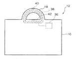
電子カセッテ12は、放射線画像を撮像する撮像プレート26と、撮像プレート26で撮像した放射線画像を記憶する画像メモリ28と、を備えており、これらは密閉されるように矩形平板状の筐体16によって被覆されている。なお、筐体16は、X線等の放射線が透過可能な材料で構成されている。  Theelectronic cassette 12 includes animaging plate 26 that captures a radiographic image and animage memory 28 that stores a radiographic image captured by theimaging plate 26, and these are sealed in a rectangular flat plate-shaped casing 16. It is covered by. Thehousing 16 is made of a material that can transmit radiation such as X-rays.

筐体16の上端面の中央部には、両端が当該上端面に固着された半環状の把持部18が設けられている。この把持部18は、ユーザが指を掛けることで把持することができる構造となっており、磁気エネルギーが透過可能な材料で構成されている。  Asemi-annular gripping portion 18 having both ends fixed to the upper end surface is provided at the center of the upper end surface of thehousing 16. Thegrip portion 18 has a structure that can be gripped by a user by placing a finger and is made of a material that can transmit magnetic energy.

なお、本第1の実施形態に係る電子カセッテ12では、筐体16の上端面に把持部18を設けているが、これに限らず、例えば、筐体16の端部にユーザが指を掛けることで把持することができる大きさの貫通孔を形成し、筐体16の当該貫通孔とその近傍を把持部とする形態等としても良い。  In theelectronic cassette 12 according to the first embodiment, thegrip portion 18 is provided on the upper end surface of thehousing 16, but the present invention is not limited thereto, and for example, the user places a finger on the end of thehousing 16. It is good also as a form etc. which form the through-hole of the magnitude | size which can be hold | gripped by this, and make the said through-hole of the housing |casing 16 and its vicinity into a holding part.

一方、クレードル14は、矩形平板状の本体部20と、本体部20の前面から当該前面に対して略直交する方向に突出した突出部22と、を含んで構成されている。クレードル14は、本体部20の背面(突出部22が設けられている面とは反対側の面)が壁などに固着されて使用される。  On the other hand, thecradle 14 includes a rectangular flat plate-shapedmain body 20 and a protrudingportion 22 that protrudes from the front surface of themain body portion 20 in a direction substantially orthogonal to the front surface. Thecradle 14 is used with the back surface of the main body 20 (the surface opposite to the surface on which theprotrusions 22 are provided) fixed to a wall or the like.

突出部22は、把持部18を掛けることが可能な構造となっており、先端部が電子カセッテ12の脱落を防止するように斜め上方に屈曲している。なお、突出部22は、磁気エネルギーが透過可能な材料で構成されている。  The protrudingportion 22 has a structure that allows the grippingportion 18 to be hung, and the tip portion is bent obliquely upward so as to prevent theelectronic cassette 12 from falling off. In addition, theprotrusion part 22 is comprised with the material which can permeate | transmit magnetic energy.

突出部22には、把持部18が掛けられた際の当該把持部18との接触面に対応する形状とされた凹部24が複数形成されている。なお、本第1の実施形態に係るクレードル14では、突出部22に凹部24が3つ形成されているが、凹部24は、突出部22の把持部18を掛けることが可能な位置に形成されていれば突出部22にいくつ形成されていても良い。また、本第1の実施形態に係るクレードル14では、凹部24の両側面の各々が底面から略垂直に立ち上がっているが、これに限らず、例えば、凹部24の両側面の各々が斜め上方を臨むようにテーパ状に形成されていている形態、側面視半円状に形成されている形態等、凹部24の形状は把持部18が掛けられた際の当該把持部18との接触面に対応する形状とされたものであれば如何なる形状としても良い。  A plurality ofrecesses 24 having a shape corresponding to a contact surface with the grippingportion 18 when the grippingportion 18 is hung are formed in the protrudingportion 22. In thecradle 14 according to the first embodiment, theprojection 22 has threerecesses 24, but therecess 24 is formed at a position where thegrip 18 of theprojection 22 can be hung. Any number ofprotrusions 22 may be formed. Further, in thecradle 14 according to the first embodiment, each of the both side surfaces of therecess 24 rises substantially perpendicularly from the bottom surface. However, the present invention is not limited to this. The shape of therecess 24 corresponds to the contact surface with the grippingportion 18 when the grippingportion 18 is hung, such as a shape that is tapered so as to face, a shape that is formed in a semicircular shape when viewed from the side. Any shape may be used as long as it is a shape to be formed.

図2には、本第1の実施形態に係る電子カセッテ12の使用方法が模式的に示されている。  FIG. 2 schematically shows how to use theelectronic cassette 12 according to the first exemplary embodiment.

同図に示されるように、電子カセッテ12は、放射線画像の撮像時に、放射線を発生する放射線発生部30と間隔を空けて配置される。放射線発生部30と電子カセッテ12の撮像面32との間には被写体34が位置し、放射線画像の撮像が指示されると、放射線発生部30は予め定められた放射線量の放射線を射出する。放射線発生部30から射出された放射線は、被写体34を透過することで画像情報を担持した後に電子カセッテ12の撮像面30に照射され、当該画像情報により示される画像が放射線画像として撮像プレート26に撮像される。  As shown in the figure, theelectronic cassette 12 is disposed at a distance from theradiation generating unit 30 that generates radiation when a radiographic image is captured. When the subject 34 is positioned between theradiation generating unit 30 and theimaging surface 32 of theelectronic cassette 12, and when an instruction to capture a radiographic image is given, theradiation generating unit 30 emits radiation having a predetermined radiation dose. The radiation emitted from theradiation generation unit 30 passes through the subject 34 to carry image information, and then irradiates theimaging surface 30 of theelectronic cassette 12. The image indicated by the image information is applied to theimaging plate 26 as a radiation image. Imaged.

図3には、本第1の実施形態に係る電子カセッテ12の透視図が示されている。  FIG. 3 shows a perspective view of theelectronic cassette 12 according to the first exemplary embodiment.

同図に示されるように、電子カセッテ12は、各部に駆動用の電力を供給する二次電池36と、磁気エネルギーを電気エネルギーに変換するコイルユニット38と、を備えている。コイルユニット38は、電磁誘導による電力が誘起されるように環状のフェライトコア及び巻き線によって形成されており、把持部18を突出部22に掛けた際に突出部22を取り囲むように把持部18及び筐体16に収納されている。コイルユニット38は二次電池36に電気的に接続されており、コイルユニット38によって誘起された電力は二次電池36へ供給される。  As shown in the figure, theelectronic cassette 12 includes asecondary battery 36 that supplies driving power to each unit, and acoil unit 38 that converts magnetic energy into electrical energy. Thecoil unit 38 is formed by an annular ferrite core and a winding so that electric power by electromagnetic induction is induced. When thegripping part 18 is hung on theprotrusion 22, thegripping part 18 is surrounded. And thehousing 16. Thecoil unit 38 is electrically connected to thesecondary battery 36, and the electric power induced by thecoil unit 38 is supplied to thesecondary battery 36.

また、電子カセッテ12は、無線LANを利用してクレードル14との間で通信を行うための無線通信用アンテナ40と、クレードル14との間で近赤外レーザ光(以下、単に「レーザ光」という。)による通信を行うためのレーザ光通信装置42と、を備えている。  Theelectronic cassette 12 also includes a near-infrared laser beam (hereinafter simply referred to as “laser beam”) between thewireless communication antenna 40 for communicating with thecradle 14 using a wireless LAN and thecradle 14. And a laserbeam communication device 42 for performing communication according to the above.

なお、本第1の実施形態に係る充電システム10では、無線LANとしてWiFi(Wireless Fidelity)を適用している。  In the chargingsystem 10 according to the first embodiment, WiFi (Wireless Fidelity) is applied as a wireless LAN.

無線通信用アンテナ40は、把持部18の上面に外部に露呈するように設けられている。また、レーザ光通信装置42は、把持部18が凹部24に嵌合された際に突出部22の下面(凹部24が形成されている面の反対側の面)に対向するように筐体16の上端面に設けられている。  Thewireless communication antenna 40 is provided on the upper surface of thegrip portion 18 so as to be exposed to the outside. Further, the laserbeam communication device 42 has ahousing 16 so as to face the lower surface of the protrusion 22 (the surface opposite to the surface on which therecess 24 is formed) when thegrip portion 18 is fitted into therecess 24. Is provided on the upper end surface of the.

図4には、本第1の実施形態に係る充電システム10の要部の側面視断面図が示されている。  FIG. 4 shows a cross-sectional side view of the main part of the chargingsystem 10 according to the first embodiment.

同図に示されるように、クレードル14は、交流電圧が印加されることにより交番磁界を発生して磁気エネルギーを電子カセッテ12のコイルユニット38に供給する電磁石44を備えている。電磁石44は、クレードル14に収納されており、突出部22の基端部から先端部にかけて延設されている。なお、本第1の実施形態では、電磁石44の磁芯が突出部22の基端部から先端部にかけて延設されているが、これに限らず、電磁石44を構成している巻き線も含めて突出部22の基端部から先端部にかけて延設されていても良い。  As shown in the figure, thecradle 14 includes anelectromagnet 44 that generates an alternating magnetic field when an alternating voltage is applied and supplies magnetic energy to thecoil unit 38 of theelectronic cassette 12. Theelectromagnet 44 is housed in thecradle 14 and extends from the proximal end portion to the distal end portion of the protrudingportion 22. In the first embodiment, the magnetic core of theelectromagnet 44 extends from the proximal end portion to the distal end portion of the protrudingportion 22, but is not limited to this, and includes the windings that constitute theelectromagnet 44. The projectingportion 22 may extend from the proximal end portion to the distal end portion.

また、クレードル14は、無線LANを利用して電子カセッテ12との間で通信を行うための無線通信用アンテナ46を備えている。無線通信用アンテナ46は、把持部18を突出部22に掛けた際に電子カセッテ12の無線通信用アンテナ40と通信可能になるように本体部20の前面に無線通信用アンテナ40を斜め下に臨むように設けられている。  Thecradle 14 also includes awireless communication antenna 46 for performing communication with theelectronic cassette 12 using a wireless LAN. Thewireless communication antenna 46 is placed diagonally downward on the front surface of themain body 20 so that thewireless communication antenna 46 can communicate with thewireless communication antenna 40 of theelectronic cassette 12 when thegrip portion 18 is hung on the protrudingportion 22. It is provided to face.

更に、クレードル14は、電子カセッテ12との間でレーザ光による通信を行うためのレーザ光通信装置48を備えている。レーザ光通信装置48は、突出部22に設けられており、突出部22の下面における凹部24が設けられている位置の直下に配置されている。従って、把持部18が凹部24に嵌合されると、レーザ光通信装置48は、電子カセッテ12のレーザ光通信装置42と対向し、電子カセッテ12とクレードル14との間でレーザ光による通信が可能な状態となる。  Further, thecradle 14 includes a laserlight communication device 48 for performing communication with theelectronic cassette 12 using laser light. The laserlight communication device 48 is provided in theprotrusion 22 and is disposed immediately below the position where therecess 24 is provided on the lower surface of theprotrusion 22. Therefore, when the grippingportion 18 is fitted into therecess 24, the laserlight communication device 48 faces the laserlight communication device 42 of theelectronic cassette 12, and communication by the laser light is performed between theelectronic cassette 12 and thecradle 14. It becomes possible.

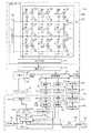
図5には、本第1の実施形態に係る充電システム10の電気系のブロック図が示されている。  FIG. 5 shows a block diagram of the electric system of the chargingsystem 10 according to the first embodiment.

同図に示されるように、電子カセッテ12の撮像プレート26は、TFTアクティブマトリクス基板50上に、放射線を吸収して電荷に変換する光電変換層が積層されて構成されている。光電変換層は例えばセレンを主成分(例えば含有率50%以上)とする非晶質のa−Se(アモルファスセレン)から成り、放射線が照射されると、照射された放射線量に応じた電荷量の電荷(電子−正孔の対)を内部で発生することで、照射された放射線を電荷へ変換する。なお、撮像プレート26は、アモルファスセレンのような放射線Xを直接的に電荷に変換するX線-電荷変換材料の代わりに、蛍光体材料と光電変換素子(フォトダイオード)を用いて間接的に電荷に変換しても良い。蛍光体材料としては、ガドリニウム硫酸化物(GOS)やヨウ化セシウム(CsI)が良く知られている。この場合、蛍光材料によってX線−光変換を行い、光電変換素子のフォトダイオードによって光−電荷変換を行なう。  As shown in the figure, theimaging plate 26 of theelectronic cassette 12 is configured by laminating a photoelectric conversion layer that absorbs radiation and converts it into charges on a TFTactive matrix substrate 50. The photoelectric conversion layer is made of amorphous a-Se (amorphous selenium) containing, for example, selenium as a main component (for example, a content rate of 50% or more), and when irradiated with radiation, the amount of charge corresponding to the amount of irradiated radiation. The generated radiation (electron-hole pair) is internally generated to convert the irradiated radiation into charges. Theimaging plate 26 is indirectly charged using a phosphor material and a photoelectric conversion element (photodiode) instead of an X-ray-charge conversion material that directly converts the radiation X such as amorphous selenium into an electric charge. May be converted to As phosphor materials, gadolinium sulfate (GOS) and cesium iodide (CsI) are well known. In this case, X-ray-light conversion is performed using a fluorescent material, and light-charge conversion is performed using a photodiode of a photoelectric conversion element.

また、TFTアクティブマトリクス基板50上には、光電変換層で発生された電荷を蓄積する蓄積容量52と、蓄積容量52に蓄積された電荷を読み出すためのTFT54を備えた画素部56(図5では個々の画素部56に対応する光電変換層を光電変換部58として模式的に示している)がマトリクス状に複数個配置されており、電子カセッテ12への放射線の照射に伴って光電変換層で発生された電荷は、個々の画素部56の蓄積容量52に蓄積される。これにより、電子カセッテ12に照射された放射線に担持されていた画像情報は電荷情報へ変換されてTFTアクティブマトリクス基板50に保持される。  Further, on the TFTactive matrix substrate 50, a pixel portion 56 (in FIG. 5, astorage capacitor 52 for storing charges generated in the photoelectric conversion layer and aTFT 54 for reading out the charges stored in the storage capacitor 52). A plurality of photoelectric conversion layers corresponding to theindividual pixel portions 56 are schematically shown as photoelectric conversion portions 58), and a plurality of photoelectric conversion layers are arranged in a matrix shape. The generated charges are stored in thestorage capacitors 52 of theindividual pixel units 56. As a result, the image information carried by the radiation applied to theelectronic cassette 12 is converted into charge information and held on the TFTactive matrix substrate 50.

また、TFTアクティブマトリクス基板50には、一定方向(行方向)に延設され個々の画素部56のTFT54をオンオフさせるための複数本のゲート配線60と、ゲート配線60と直交する方向(列方向)に延設されオンされたTFT54を介して蓄積容量52から蓄積電荷を読み出すための複数本のデータ配線62が設けられている。個々のゲート配線60はゲート線ドライバ64に接続されており、個々のデータ配線62は信号処理部66に接続されている。個々の画素部56の蓄積容量52に電荷が蓄積されると、個々の画素部56のTFT54は、ゲート線ドライバ64からゲート配線60を介して供給される信号により行単位で順にオンされ、TFT54がオンされた画素部56の蓄積容量52に蓄積されている電荷は、電荷信号としてデータ配線62を介して信号処理部66に入力される。従って、個々の画素部56の蓄積容量52に蓄積されている電荷は行単位で順に読み出される。  The TFTactive matrix substrate 50 has a plurality ofgate lines 60 extending in a certain direction (row direction) for turning on and off theTFTs 54 of theindividual pixel portions 56 and a direction (column direction) orthogonal to the gate lines 60. A plurality of data wirings 62 are provided for reading the stored charge from thestorage capacitor 52 through theTFT 54 that is extended and turned on.Individual gate lines 60 are connected to agate line driver 64, andindividual data lines 62 are connected to asignal processing unit 66. When charges are accumulated in thestorage capacitors 52 of theindividual pixel units 56, theTFTs 54 of theindividual pixel units 56 are sequentially turned on in units of rows by a signal supplied from thegate line driver 64 via thegate wiring 60. The charge stored in thestorage capacitor 52 of thepixel unit 56 for which is turned on is input to thesignal processing unit 66 through the data wiring 62 as a charge signal. Accordingly, the charges accumulated in thestorage capacitors 52 of theindividual pixel portions 56 are sequentially read out in units of rows.

図示は省略するが、信号処理部66は、個々のデータ配線62毎に設けられた増幅器及びサンプルホールド回路を備えており、個々のデータ配線62を伝送された電荷信号は増幅器で増幅された後にサンプルホールド回路に保持される。また、サンプルホールド回路の出力側にはマルチプレクサ、A/D変換器が順に接続されており、個々のサンプルホールド回路に保持された電荷信号はマルチプレクサに順に(シリアルに)入力され、A/D変換器によってデジタルの画像情報へ変換される。信号処理部66には画像メモリ28が接続されており、信号処理部66のA/D変換器から出力された画像情報は画像メモリ28に順に記憶される。画像メモリ28は複数フレーム分の画像情報を記憶可能な記憶容量を有しており、放射線画像の撮像が行われる毎に、撮像によって得られた画像情報が画像メモリ28に順次記憶される。  Although not shown, thesignal processing unit 66 includes an amplifier and a sample-and-hold circuit provided for eachdata wiring 62. After the charge signal transmitted through each data wiring 62 is amplified by the amplifier, It is held in the sample hold circuit. In addition, a multiplexer and an A / D converter are connected in order to the output side of the sample and hold circuit, and the charge signals held in the individual sample and hold circuits are input to the multiplexer in order (serially) for A / D conversion. Is converted into digital image information. Animage memory 28 is connected to thesignal processing unit 66, and image information output from the A / D converter of thesignal processing unit 66 is sequentially stored in theimage memory 28. Theimage memory 28 has a storage capacity capable of storing image information for a plurality of frames, and image information obtained by imaging is sequentially stored in theimage memory 28 every time a radiographic image is captured.

レーザ光通信装置42は、レーザ光を射出するLD(レーザダイオード)70と、外部から入射されたレーザ光を検出するPD(フォトダイオード)72と、を含んで構成されている。  The laserlight communication device 42 includes an LD (laser diode) 70 that emits laser light and a PD (photodiode) 72 that detects laser light incident from the outside.

LD70は変調部74を介して通信制御部76に接続されている。通信制御部76は、マイクロコンピュータによって実現され、クレードル14への情報の送信時に、送信対象の情報を変調部74へ出力すると共に、LD70から射出するレーザ光の強度を変調部74へ指示する。変調部74は、LD70から射出されるレーザ光を入力された送信対象の情報に応じて所定の変調方式で変調すると共に、LD70から射出されるレーザ光の強度が指示された強度に一致するようにLD70の駆動を制御する。これにより、LD70からは、送信対象の情報に応じて変調されたレーザ光が、通信制御部76から指示された強度で射出される。  TheLD 70 is connected to thecommunication control unit 76 via themodulation unit 74. Thecommunication control unit 76 is realized by a microcomputer, and when transmitting information to thecradle 14, outputs information to be transmitted to themodulation unit 74 and instructs themodulation unit 74 about the intensity of the laser light emitted from theLD 70. Themodulation unit 74 modulates the laser light emitted from theLD 70 by a predetermined modulation method according to the input information to be transmitted, and makes the intensity of the laser light emitted from theLD 70 coincide with the instructed intensity. The driving of theLD 70 is controlled. Thereby, the laser beam modulated according to the information to be transmitted is emitted from theLD 70 with the intensity instructed from thecommunication control unit 76.

また、PD72は、復調部78を介して通信制御部76に接続されている。復調部78は、外部からのレーザ光がPD72で受光され、レーザ光の受光量に応じた受光量信号がPD72から入力されると、入力された受光量信号に基づいて、受光されたレーザ光が担持している情報(通信相手の装置から送信された情報)を所定の復調方式で復調し、復調した情報を通信制御部76へ出力する。  ThePD 72 is connected to thecommunication control unit 76 via thedemodulation unit 78. When the external laser beam is received by thePD 72 and a received light amount signal corresponding to the received light amount of the laser beam is input from thePD 72, thedemodulator 78 receives the received laser light based on the received received light amount signal. Is demodulated with a predetermined demodulation method, and the demodulated information is output to thecommunication control unit 76.

電子カセッテ12は、無線通信部80を含んで構成されている。無線通信用アンテナ40は無線通信部80を介して通信制御部76に接続されている。通信制御部76は、クレードル14への情報の送信時に、送信対象の情報を無線通信部80に出力する。無線通信部80は、通信制御部76から入力された送信対象の情報を無線通信用アンテナ40を介してクレードル14へ無線で送信する。  Theelectronic cassette 12 includes awireless communication unit 80. Theradio communication antenna 40 is connected to thecommunication control unit 76 via theradio communication unit 80. Thecommunication control unit 76 outputs information to be transmitted to thewireless communication unit 80 when transmitting information to thecradle 14. Thewireless communication unit 80 wirelessly transmits the transmission target information input from thecommunication control unit 76 to thecradle 14 via thewireless communication antenna 40.

無線通信部80は、外部からの電波が無線通信用アンテナ40で受信され、当該電波に応じた信号が無線通信用アンテナ40から入力されると、入力された信号に基づいて、受信された電波が担持している情報を通信制御部76へ出力する。  When theradio communication unit 80 receives an external radio wave from theradio communication antenna 40 and receives a signal corresponding to the radio wave from theradio communication antenna 40, theradio communication unit 80 receives the radio wave based on the input signal. Is carried to thecommunication control unit 76.

また、電子カセッテ12は、装置の電源スイッチが切られても保持しなければならない各種情報を記憶するNVM(Non Volatile Memory:不揮発性メモリ)82を含んで構成されている。通信制御部76はNVM82に接続されており、NVM82への情報の書き込み、及びNVM82からの情報の読み出しを行うことができる。  Theelectronic cassette 12 includes an NVM (Non Volatile Memory) 82 that stores various types of information that must be retained even when the apparatus is turned off. Thecommunication control unit 76 is connected to theNVM 82 and can write information to theNVM 82 and read information from theNVM 82.

これに対し、クレードル14は、クレードル14全体の動作を司るCPU(中央処理装置)84と、DC(直流)/AC(交流)コンバータ86と、DC電源88と、を含んで構成されている。CPU84には、DC/ACコンバータ86が接続されており、DC/ACコンバータ86の駆動はCPU84によって制御される。  On the other hand, thecradle 14 includes a CPU (central processing unit) 84 that controls the operation of thecradle 14 as a whole, a DC (direct current) / AC (alternating current) converter 86, and aDC power source 88. A DC / AC converter 86 is connected to theCPU 84, and driving of the DC / AC converter 86 is controlled by theCPU 84.

また、DC/ACコンバータ86のDC電力の入力端にはDC電源88が接続されており、DC/ACコンバータ86はCPU84の制御下で、DC電源88から供給された直流の電力を交流の電力に変換する役割を有している。  ADC power supply 88 is connected to the DC power input terminal of the DC / AC converter 86. The DC / AC converter 86 converts the DC power supplied from theDC power supply 88 under the control of theCPU 84 to AC power. Has the role of converting to

更に、DC/ACコンバータ86とDC電源88の負電極との間には、この位置において流れる電流(以下、「充電電流」という。)の大きさを検出する電流検出部90が介在されており、電流検出部90における検出した充電電流の大きさを示す信号を出力する出力端はCPU84に接続されている。従って、CPU84は、必要に応じて充電電流の大きさを把握することができる。  Further, acurrent detector 90 for detecting the magnitude of a current flowing at this position (hereinafter referred to as “charging current”) is interposed between the DC / AC converter 86 and the negative electrode of theDC power supply 88. The output terminal for outputting a signal indicating the magnitude of the charging current detected by thecurrent detector 90 is connected to theCPU 84. Therefore, theCPU 84 can grasp the magnitude of the charging current as necessary.

また、クレードル14は、NVM92を含んで構成されている。CPU84はNVM92に接続されており、NVM92への情報の書き込み、及びNVM92からの情報の読み出しを行うことができる。  Thecradle 14 includes anNVM 92. TheCPU 84 is connected to theNVM 92 and can write information to theNVM 92 and read information from theNVM 92.

また、クレードル14は、外部インタフェース96を含んで構成されている。外部インタフェース96は、パーソナル・コンピュータ(以下、「PC」という。)94に接続され、PC94との間で各種情報を送受信するためのものである。CPU84は外部インタフェース96に接続されており、PC94との外部インタフェース96を介した各種情報の送受信を行うことができる。  Thecradle 14 includes an external interface 96. The external interface 96 is connected to a personal computer (hereinafter referred to as “PC”) 94 and transmits / receives various information to / from thePC 94. TheCPU 84 is connected to the external interface 96 and can transmit and receive various types of information to and from thePC 94 via the external interface 96.

レーザ光通信装置48は、レーザ光を射出するLD98と、外部から入射されたレーザ光を検出するPD100と、を含んで構成されている。  The laserlight communication device 48 includes anLD 98 that emits laser light and aPD 100 that detects laser light incident from the outside.

LD98は、変調部102を介してCPU84に接続されている。CPU84は、電子カセッテ12への情報の送信時に、送信対象の情報を変調部102へ出力すると共に、LD98から射出するレーザ光の強度を変調部102へ指示する。変調部102は、LD98から射出されるレーザ光を入力された送信対象の情報に応じて所定の変調方式で変調すると共に、LD98から射出されるレーザ光の強度が指示された強度に一致するようにLD98の駆動を制御する。これにより、LD98からは、送信対象の情報に応じて変調されたレーザ光が、CPU84から指示された強度で射出される。  TheLD 98 is connected to theCPU 84 via themodulation unit 102. When transmitting information to theelectronic cassette 12, theCPU 84 outputs information to be transmitted to themodulation unit 102 and instructs themodulation unit 102 about the intensity of the laser light emitted from theLD 98. Themodulation unit 102 modulates the laser light emitted from theLD 98 with a predetermined modulation method according to the input transmission target information, and matches the intensity of the laser light emitted from theLD 98 with the instructed intensity. The drive of theLD 98 is controlled. Thereby, the laser beam modulated according to the information to be transmitted is emitted from theLD 98 with the intensity instructed by theCPU 84.

また、PD100は、復調部104を介してCPU84に接続されている。復調部104は、外部からのレーザ光がPD100で受光され、レーザ光の受光量に応じた受光量信号がPD100から入力されると、入力された受光量信号に基づいて、受光されたレーザ光が担持している情報(通信相手の装置から送信された情報)を所定の復調方式で復調し、復調した情報をCPU84へ出力する。  ThePD 100 is connected to theCPU 84 via thedemodulator 104. When the laser beam from the outside is received by thePD 100 and a received light amount signal corresponding to the received light amount of the laser beam is input from thePD 100, thedemodulator 104 receives the received laser beam based on the received received light amount signal. Is demodulated with a predetermined demodulation method, and the demodulated information is output to theCPU 84.

電子カセッテ12は、無線通信部106を含んで構成されている。無線通信用アンテナ46は無線通信部106を介してCPU84に接続されている。CPU84は、電子カセッテ12への情報の送信時に、送信対象の情報を無線通信部106に出力する。無線通信部106は、CPU84から入力された送信対象の情報を無線通信用アンテナ46を介して電子カセッテ12へ無線で送信する。  Theelectronic cassette 12 includes awireless communication unit 106. Thewireless communication antenna 46 is connected to theCPU 84 via thewireless communication unit 106. TheCPU 84 outputs information to be transmitted to thewireless communication unit 106 when transmitting information to theelectronic cassette 12. Thewireless communication unit 106 wirelessly transmits the transmission target information input from theCPU 84 to theelectronic cassette 12 via thewireless communication antenna 46.

無線通信部106は、外部からの電波が無線通信用アンテナ46で受信され、当該電波に応じた信号が無線通信用アンテナ46から入力されると、入力された信号に基づいて、受信された電波が担持している情報をCPU84へ出力する。  When theradio communication unit 106 receives a radio wave from the outside by theradio communication antenna 46 and inputs a signal corresponding to the radio wave from theradio communication antenna 46, theradio communication unit 106 receives the received radio wave based on the input signal. The information carried by is output to theCPU 84.

次に、本第1の実施形態に係る充電システム10の作用として、先ず、図6を参照して、クレードル14の作用を説明する。なお、図6は、電子カセッテ12の把持部18がクレードル14の凹部24に嵌合された際にクレードル14のCPU84により実行されるクレードル処理プログラムの処理の流れを示すフローチャートであり、当該プログラムはNVM92の所定領域に予め記憶されている。  Next, as an operation of the chargingsystem 10 according to the first embodiment, first, an operation of thecradle 14 will be described with reference to FIG. FIG. 6 is a flowchart showing a processing flow of a cradle processing program executed by theCPU 84 of thecradle 14 when thegrip portion 18 of theelectronic cassette 12 is fitted in therecess 24 of thecradle 14. Pre-stored in a predetermined area of theNVM 92.

なお、本第1の実施形態に係る充電システム10では、電子カセッテ12の把持部18がクレードル14の凹部24に嵌合されたか否かを、凹部24の底の把持部18が当接する位置に設けられたマイクロスイッチ(図示省略)がオン状態となったか否かを判定することにより検知しているが、これに限らず、例えば、凹部24の側壁にフォトセンサを設け、当該フォトセンサの光が遮られた否かを判定することにより電子カセッテ12の把持部18がクレードル14の凹部24に嵌合されたか否かを検知する等といった形態とすることもできる。  In the chargingsystem 10 according to the first embodiment, whether or not thegrip portion 18 of theelectronic cassette 12 is fitted in therecess 24 of thecradle 14 is determined at a position where thegrip portion 18 at the bottom of therecess 24 abuts. The detection is performed by determining whether or not the provided microswitch (not shown) is turned on. However, the present invention is not limited to this. For example, a photosensor is provided on the side wall of therecess 24, and light from the photosensor It may be configured to detect whether or not thegrip portion 18 of theelectronic cassette 12 is fitted into therecess 24 of thecradle 14 by determining whether or not is blocked.

同図のステップ200では、DC/ACコンバータ86の発振を開始することにより、二次電池36を高速かつ安全に充電することのできる上限の電圧として予め定められた基準電圧の電力を電子カセッテ12のコイルユニット38に対して誘起させることのできる交流電圧の印加を開始する。  Instep 200 of the figure, by starting the oscillation of the DC / AC converter 86, the power of the reference voltage set in advance as the upper limit voltage that can charge thesecondary battery 36 at high speed and safely can be obtained. Application of an alternating voltage that can be induced to thecoil unit 38 is started.

本第1の実施形態に係る充電システム10では、上記ステップ200の処理によって電磁石44に印加された交流電圧に応じてコイルユニット38によって交番電力が誘起され、二次電池36に供給される。  In the chargingsystem 10 according to the first embodiment, alternating power is induced by thecoil unit 38 in accordance with the alternating voltage applied to theelectromagnet 44 by the process ofstep 200 and is supplied to thesecondary battery 36.

次のステップ202では、電子カセッテ12に対して、当該電子カセッテ12との間で正常な通信を行うことができるか否かを判定するための予め定められた情報の送信を要求することを示す所定情報送信要求情報を送信する。ステップ202にて所定情報送信要求情報を送信することにより、後述するように電子カセッテ12から予め定められた情報が送信される。そこで、次のステップ204では、電子カセッテ12から送信される予め定められた情報の受信待ちを行う。  In thenext step 202, it is indicated that theelectronic cassette 12 is requested to transmit predetermined information for determining whether normal communication with theelectronic cassette 12 can be performed. The predetermined information transmission request information is transmitted. By transmitting the predetermined information transmission request information instep 202, predetermined information is transmitted from theelectronic cassette 12 as will be described later. Therefore, in thenext step 204, reception of predetermined information transmitted from theelectronic cassette 12 is waited for.

なお、本第1の実施形態に係る充電システム10では、レーザ光通信装置42,48により電子カセッテ12とクレードル14との間で情報の授受を行っているが、これに限らず、無線通信用アンテナ40,46により電子カセッテ12とクレードル14との間で情報の授受を行っても良い。また、本第1の実施形態に係る充電システム10では、PC94を介してクレードル14に入力されるユーザからの指示に応じてレーザ光通信を行うか、無線LAN通信を行うかが決定される。  In the chargingsystem 10 according to the first embodiment, information is exchanged between theelectronic cassette 12 and thecradle 14 by the laserlight communication devices 42 and 48. However, the present invention is not limited to this. Information may be exchanged between theelectronic cassette 12 and thecradle 14 by theantennas 40 and 46. In the chargingsystem 10 according to the first embodiment, whether to perform laser light communication or wireless LAN communication is determined according to an instruction from the user input to thecradle 14 via thePC 94.

ステップ206では、上記ステップ204で受信した情報に対するビットエラーレート(BER)が良好か否かを判定し、肯定判定となった場合にはステップ208へ移行し、電子カセッテ12に対して、画像メモリ28に記憶されている全ての画像情報(以下、「本画像情報」という。)の送信を要求することを示す本画像送信要求情報を送信する。  Instep 206, it is determined whether or not the bit error rate (BER) for the information received instep 204 is good. If the determination is affirmative, the process proceeds to step 208, and theelectronic cassette 12 receives the image memory. The main image transmission request information indicating that transmission of all the image information (hereinafter referred to as “main image information”) stored in 28 is requested is transmitted.

ステップ208にて本画像送信要求情報を送信することにより、後述するように電子カセッテ12から本画像情報が送信される。そこで、次のステップ210では、電子カセッテ12から送信される本画像情報の受信待ちを行う。本画像情報の受信が終了すると、上記ステップ210の処理が肯定判定となってステップ234へ移行する。  By transmitting the main image transmission request information instep 208, the main image information is transmitted from theelectronic cassette 12 as will be described later. Therefore, in thenext step 210, the reception of the main image information transmitted from theelectronic cassette 12 is awaited. When the reception of the main image information is completed, the process ofstep 210 is affirmative and the process proceeds to step 234.

一方、ステップ206において否定判定となった場合には、ステップ212へ移行し、二次電池36の電力の残量が第1所定値以上かつ第2所定値未満であるか否かを判定し、肯定判定となった場合にはステップ214へ移行する。  On the other hand, when a negative determination is made atstep 206, the routine proceeds to step 212, where it is determined whether or not the remaining power of thesecondary battery 36 is greater than or equal to a first predetermined value and less than a second predetermined value. If the determination is affirmative, the routine proceeds to step 214.

なお、上記第1所定値は、画像メモリ28に記憶されている全ての画像情報のうちの一部を間引いた画像情報、すなわち、ユーザが画像を見て撮像が正しく行われたか否かを確認することができるだけの画像情報(以下、「確認用画像情報」という。)を送信することができるだけの電力に相当する値であり、上記第2所定値は、本画像情報を送信することができるだけの電力に相当する値である。  The first predetermined value is the image information obtained by thinning out a part of all the image information stored in theimage memory 28, that is, confirms whether or not the user has taken the image correctly by looking at the image. The image information (hereinafter referred to as “confirmation image information”) that can be transmitted is a value corresponding to power that can be transmitted, and the second predetermined value can transmit the image information. It is a value corresponding to the power of.

また、本第1の実施形態に係る充電システム10では、上記ステップ212の処理を実行するに当り、クレードル14が電子カセッテ12に対して二次電池36の電力の残量を示す電力残量情報の送信を要求することを示す情報を送信する。これに応じて、電子カセッテ12は電力残量情報をクレードル14に送信する。そして、クレードル14は、電子カセッテ12から送信された電力残量情報を受信し、電力残量情報により示される二次電池36の電力の残量が上記第1所定値以上かつ上記第2所定値未満であるか否かを判定する。  In the chargingsystem 10 according to the first embodiment, the remaining power information indicating the remaining power of thesecondary battery 36 with respect to theelectronic cassette 12 when thecradle 14 performs the process ofstep 212. The information indicating that the transmission is requested is transmitted. In response to this, theelectronic cassette 12 transmits remaining power information to thecradle 14. Thecradle 14 receives the remaining power information transmitted from theelectronic cassette 12, and the remaining power of thesecondary battery 36 indicated by the remaining power information is greater than or equal to the first predetermined value and the second predetermined value. It is judged whether it is less than.

ステップ214では、DC/ACコンバータ86の発振を停止し、次のステップ216では、電子カセッテ12に対して、確認用画像情報の送信を要求することを示す確認用画像送信要求情報を送信する。  Instep 214, the oscillation of the DC / AC converter 86 is stopped, and in thenext step 216, confirmation image transmission request information indicating that transmission of confirmation image information is requested is transmitted to theelectronic cassette 12.

ステップ216にて確認用画像送信要求情報を送信することにより、後述するように電子カセッテ12から確認用画像情報が送信される。そこで、次のステップ218では、電子カセッテ12から送信される確認用画像情報の受信待ちを行う。確認用画像情報の受信が終了すると、上記ステップ218の処理が肯定判定となってステップ220へ移行する。  By transmitting the confirmation image transmission request information instep 216, the confirmation image information is transmitted from theelectronic cassette 12 as will be described later. Therefore, in thenext step 218, reception of the confirmation image information transmitted from theelectronic cassette 12 is awaited. When the reception of the confirmation image information is completed, the process instep 218 is affirmative and the process proceeds to step 220.

ステップ220では、上記ステップ200と同様の処理を実行し、次のステップ222にて、電流検出部90から入力された信号により示される充電電流の大きさが、本画像情報を送信することができるだけの電力が充電されたときの充電電流の大きさとして予め定められた閾値以上となるまで待機し、その後にステップ226へ移行する。  Instep 220, the same processing as instep 200 is executed. In thenext step 222, the magnitude of the charging current indicated by the signal input from thecurrent detection unit 90 can transmit the main image information. Wait until the magnitude of the charging current when the electric power is charged exceeds a predetermined threshold value, and then move to step 226.

一方、ステップ212において否定判定となった場合には、ステップ224へ移行し、二次電池36の電力の残量が上記第1所定値未満であるか否かを判定し、肯定判定となった場合にはステップ222へ移行する一方、否定判定となった場合にはステップ226へ移行する。  On the other hand, if a negative determination is made instep 212, the process proceeds to step 224, in which it is determined whether the remaining power of thesecondary battery 36 is less than the first predetermined value, and an affirmative determination is made. In this case, the process proceeds to step 222, whereas if the determination is negative, the process proceeds to step 226.

ステップ226では、DC/ACコンバータ86の発振を停止し、次のステップ228にて、電子カセッテ12に対して本画像送信要求情報を送信する。  Instep 226, the oscillation of the DC / AC converter 86 is stopped, and the next image transmission request information is transmitted to theelectronic cassette 12 in thenext step 228.

ステップ228にて本画像送信要求情報を送信することにより、後述するように電子カセッテ12から本画像情報が送信される。そこで、次のステップ230では、電子カセッテ12から送信される本画像情報の受信待ちを行う。本画像情報の受信が終了すると、上記ステップ230の処理が肯定判定となってステップ232へ移行する。  By transmitting the main image transmission request information instep 228, the main image information is transmitted from theelectronic cassette 12 as will be described later. Therefore, in thenext step 230, reception of the main image information transmitted from theelectronic cassette 12 is awaited. When the reception of the main image information is completed, the process ofstep 230 is affirmative and the process proceeds to step 232.

ステップ232では、上記ステップ200と同様の処理を実行し、次のステップ234にて、電流検出部90から入力された信号により示される充電電流の大きさが、二次電池36の充電完了時の充電電流の大きさとして予め定められた閾値以上となるまで待機し、次のステップ236にて、DC/ACコンバータ86の発振を停止した後、本クレードル処理プログラムを終了する。  Instep 232, the same processing as instep 200 is executed, and in thenext step 234, the magnitude of the charging current indicated by the signal input from thecurrent detection unit 90 is equal to that when thesecondary battery 36 is fully charged. Wait until the magnitude of the charging current becomes equal to or greater than a predetermined threshold, stop oscillation of the DC / AC converter 86 in thenext step 236, and then terminate the cradle processing program.

次に、クレードル14との間で通信する際の電子カセッテ12の作用を説明する。なお、図7は、所定期間(一例として1秒)毎に通信制御部76により実行される電子カセッテ処理プログラムの処理の流れを示すフローチャートであり、当該プログラムはNVM82の所定領域に予め記憶されている。  Next, the operation of theelectronic cassette 12 when communicating with thecradle 14 will be described. FIG. 7 is a flowchart showing the flow of processing of the electronic cassette processing program executed by thecommunication control unit 76 every predetermined period (for example, 1 second). The program is stored in a predetermined area of theNVM 82 in advance. Yes.

同図のステップ250では、前述したクレードル処理プログラムの上記ステップ202の処理によりクレードル14に対して送信させた所定情報送信要求情報の受信待ちを行う。  Instep 250 of the figure, reception of the predetermined information transmission request information transmitted to thecradle 14 by the processing ofstep 202 of the cradle processing program described above is performed.

次のステップ252では、クレードル14に対して、前述した所定情報を送信し、次のステップ254にて、前述したクレードル処理プログラムの上記ステップ208又は上記ステップ228の処理によりクレードル14に対して送信させた本画像送信要求情報を受信したか否かを判定し、否定判定となった場合にはステップ256へ移行し、上記ステップ216の処理によりクレードル14に対して送信させた確認用画像送信要求情報を受信したか否かを判定し、否定判定となった場合にはステップ254へ戻る一方、肯定判定となった場合にはステップ258へ移行する。  In thenext step 252, the above-mentioned predetermined information is transmitted to thecradle 14, and in thenext step 254, it is transmitted to thecradle 14 by the processing instep 208 or step 228 of the cradle processing program described above. It is determined whether the main image transmission request information has been received. If the determination is negative, the process proceeds to step 256, and the confirmation image transmission request information transmitted to thecradle 14 by the process ofstep 216 is performed. If the determination is negative, the process returns to step 254. If the determination is affirmative, the process proceeds to step 258.

ステップ258では、クレードル14に対して、前述した確認用画像情報を送信する。  Instep 258, the aforementioned confirmation image information is transmitted to thecradle 14.

一方、ステップ254にて肯定判定となった場合にはステップ260へ移行し、クレードル14に対して、前述した本画像情報を送信した後、本電子カセッテ処理プログラムを終了する。  On the other hand, when an affirmative determination is made instep 254, the process proceeds to step 260, and after transmitting the above-described main image information to thecradle 14, the electronic cassette processing program is terminated.

以上詳細に説明したように、本第1の実施形態に係る充電システム10では、外部からエネルギーを受給するコイルユニット38が収納された把持部18、及びコイルユニット38によって受給されたエネルギーが供給されて充電される二次電池36を有する電子カセッテ12と、コイルユニット38にエネルギーを供給する電磁石44が収納されると共に、把持部18が掛けられた際の当該把持部18との接触面に対応する形状の凹部24が形成された突出部22を有するクレードル14と、を備えており、電子カセッテ12の把持部18をクレードル14の突出部22の凹部24に嵌め込んだ状態で充電を行うことができるので、電子カセッテ18を容易に所定の充電位置に位置決めすることができる。  As described in detail above, in the chargingsystem 10 according to the first embodiment, the grippingunit 18 in which thecoil unit 38 that receives energy from the outside is stored, and the energy received by thecoil unit 38 are supplied. Theelectronic cassette 12 having therechargeable battery 36 charged and theelectromagnet 44 for supplying energy to thecoil unit 38 are housed, and correspond to the contact surface with the grippingportion 18 when the grippingportion 18 is hung. And acradle 14 having aprotrusion 22 formed with arecess 24 having a shape to be charged, and charging is performed in a state where thegrip 18 of theelectronic cassette 12 is fitted in therecess 24 of theprotrusion 22 of thecradle 14. Therefore, theelectronic cassette 18 can be easily positioned at a predetermined charging position.

また、本第1の実施形態に係る充電システム10では、コイルユニット38が、受給した磁気エネルギーを電気エネルギーとして二次電池36に供給しているので、密閉性を損なうことなく電子カセッテ12の二次電池36を充電することができる。  Further, in the chargingsystem 10 according to the first embodiment, since thecoil unit 38 supplies the received magnetic energy as electric energy to thesecondary battery 36, theelectronic cassette 12 of theelectronic cassette 12 is not damaged without impairing the sealing performance. Thesecondary battery 36 can be charged.

また、本第1の実施形態に係る充電システム10では、電磁石44が、突出部22の基端部から先端部にかけて延設されているので、把持部18が突出部22の凹部24以外の位置に掛けられた場合にも電子カセッテ12の二次電池36を充電することができる。  Further, in the chargingsystem 10 according to the first embodiment, since theelectromagnet 44 extends from the proximal end portion to the distal end portion of the protrudingportion 22, the grippingportion 18 is located at a position other than the recessedportion 24 of the protrudingportion 22. Thesecondary battery 36 of theelectronic cassette 12 can be charged even when it is applied to the battery.

また、本第1の実施形態に係る充電システム10では、電子カセッテ12が、クレードル14との間で通信を行うレーザ光通信装置42を備え、クレードル14が、把持部18が突出部22に掛けられた際にレーザ光通信装置42との間で通信可能となるレーザ光通信装置48を備えているので、電子カセッテ12の充電を行うと同時に電子カセッテ12とクレードル14との間で通信を行うことができるので、ユーザにとっての利便性を向上させることができる。  Further, in the chargingsystem 10 according to the first embodiment, theelectronic cassette 12 includes the laserlight communication device 42 that communicates with thecradle 14, and thecradle 14 has the grippingportion 18 hung on the protrudingportion 22. Since the laseroptical communication device 48 that enables communication with the laseroptical communication device 42 is provided when theelectronic cassette 12 is charged, theelectronic cassette 12 is charged and at the same time the communication between theelectronic cassette 12 and thecradle 14 is performed. Therefore, convenience for the user can be improved.

〔第2の実施形態〕  [Second Embodiment]

上記第1の実施形態では、電子カセッテ12がクレードル14から得た磁気エネルギーを電気エネルギーに変換し、当該電気エネルギーを二次電池36に供給する場合の形態例を挙げて説明したが、本第2の実施形態では、光エネルギーを電気エネルギーに変換し、当該電気エネルギーを二次電池36に供給する場合の形態例について説明する。  In the first embodiment, theelectronic cassette 12 converts the magnetic energy obtained from thecradle 14 into electric energy and supplies the electric energy to thesecondary battery 36. However, the first embodiment has been described. In the second embodiment, an example in which light energy is converted into electric energy and the electric energy is supplied to thesecondary battery 36 will be described.

先ず、図8を参照して、本第2の実施形態に係る充電システム10Bの構成を説明する。なお、本第2の実施形態に係る充電システム10Bにおいて、図1〜図5と同一の構成要素には図1〜図5と同一の符号を付して、その説明を省略する。  First, the configuration of the charging system 10B according to the second embodiment will be described with reference to FIG. In the charging system 10B according to the second embodiment, the same components as those in FIGS. 1 to 5 are denoted by the same reference numerals as those in FIGS.

同図に示されるように、充電システム10Bは、電子カセッテ12Bと、電子カセッテ12Bの充電を行うクレードル14Bと、を含んで構成されている。  As shown in the figure, the charging system 10B includes an electronic cassette 12B and acradle 14B that charges the electronic cassette 12B.

本第2の実施形態に係る電子カセッテ12Bは、上記第1の実施形態で説明した電子カセッテ12と比較して、コイルユニット38が除かれている点、レーザ光通信装置42に代えてPD300が設けられている点が異なっており、本第2の実施形態に係るクレードル14Bは、上記第1の実施形態で説明したクレードル14と比較して、電磁石44が除かれている点、レーザ光通信装置48に代えてLD302が設けられている点が異なっている。  The electronic cassette 12B according to the second embodiment is different from theelectronic cassette 12 described in the first embodiment in that thecoil unit 38 is removed, and thePD 300 is replaced with the laserlight communication device 42. Thecradle 14B according to the second embodiment is different from thecradle 14 described in the first embodiment in that theelectromagnet 44 is removed, and laser light communication is performed. The difference is that anLD 302 is provided instead of thedevice 48.

図9には、本第2の実施形態に係る充電システム10Bの電気系のブロック図が示されている。  FIG. 9 shows a block diagram of an electric system of the charging system 10B according to the second embodiment.

同図に示されるように、電子カセッテ12Bは、撮像プレート26、画像メモリ28、二次電池36、無線通信用アンテナ40、通信制御部76、無線通信部80、NVM82及びPD300を含んで構成されている。  As shown in the figure, the electronic cassette 12B includes animaging plate 26, animage memory 28, asecondary battery 36, awireless communication antenna 40, acommunication control unit 76, awireless communication unit 80, anNVM 82, and aPD 300. ing.

一方、クレードル14Bは、無線通信用アンテナ46、CPU84、DC電源88、NVM92、外部インタフェース96、無線通信部106、LD302及びドライバ304を含んで構成されている。ドライバ304は、CPU84及びDC電源88に接続されており、CPU84の制御下で、LD302の駆動を制御している。  On the other hand, thecradle 14B includes awireless communication antenna 46, aCPU 84, aDC power supply 88, anNVM 92, an external interface 96, awireless communication unit 106, anLD 302, and adriver 304. Thedriver 304 is connected to theCPU 84 and theDC power source 88, and controls the driving of theLD 302 under the control of theCPU 84.

次に、図10を参照して、本第2の実施形態に係る充電システム10Bにおけるクレードル14Bの作用を説明する。なお、図10は、電子カセッテ12Bの把持部18がクレードル14Bの凹部24に嵌合された際にクレードル14BのCPU84により実行されるクレードル処理プログラムの処理の流れを示すフローチャートであり、当該プログラムはNVM92の所定領域に予め記憶されている。また、図10における図6に示されるプログラムと同一の処理を行うステップについては図6と同一のステップ番号を付して、その説明を省略する。また、本第2の実施形態に係る充電システム10Bでは、無線通信用アンテナ40,46により電子カセッテ12Bとクレードル14Bとの間で情報の授受を行うものとする。  Next, the operation of thecradle 14B in the charging system 10B according to the second embodiment will be described with reference to FIG. FIG. 10 is a flowchart showing a processing flow of a cradle processing program executed by theCPU 84 of thecradle 14B when the grippingportion 18 of the electronic cassette 12B is fitted in therecess 24 of thecradle 14B. Pre-stored in a predetermined area of theNVM 92. Further, steps in FIG. 10 that perform the same processing as the program shown in FIG. 6 are denoted by the same step numbers as those in FIG. In the charging system 10B according to the second embodiment, information is exchanged between the electronic cassette 12B and thecradle 14B by thewireless communication antennas 40 and 46.

同図のステップ200B,220B,232Bでは、ドライバ304の駆動を開始することにより、LD302によるレーザ光の射出を開始する。LD302から射出されたレーザ光はPD300によって電力に変換され、当該電力が二次電池36に供給される。  Insteps 200B, 220B, and 232B in the figure, the laser light emission by theLD 302 is started by starting the driving of thedriver 304. Laser light emitted from theLD 302 is converted into electric power by thePD 300, and the electric power is supplied to thesecondary battery 36.

ステップ214B,226B,236Bでは、ドライバ304の駆動を停止することにより、LD302によるレーザ光の射出を停止する。  Insteps 214B, 226B, and 236B, by stopping the driving of thedriver 304, the laser beam emission by theLD 302 is stopped.

ステップ222Bでは、本画像情報を送信することができるだけの電力が充電されるまで待機する。なお、本第2の実施形態に係るクレードル14Bでは、本ステップ222Bの処理として、無線LAN通信により電子カセッテ12Bにおける二次電池36の電力の残量を示す情報を取得し、当該情報により示される二次電池36の電力の残量が本画像情報を送信することができるだけのものであるか否かを判定する処理を適用しているが、これに限らず、他の方法を用いて二次電池36の電力の残量が本画像情報を送信することができるだけのものであるか否かを判定するようにしても良い。  Instep 222B, the process waits until power sufficient to transmit the main image information is charged. In thecradle 14B according to the second embodiment, information indicating the remaining power of thesecondary battery 36 in the electronic cassette 12B is acquired by wireless LAN communication as the processing ofstep 222B, and is indicated by the information. Although the process of determining whether or not the remaining amount of power of thesecondary battery 36 can only transmit the main image information is applied, the present invention is not limited to this, and other methods may be used to perform secondary processing. It may be determined whether or not the remaining amount of power of thebattery 36 is sufficient to transmit the main image information.

ステップ234Bでは、二次電池36の充電が完了するまで待機する。なお、本第2の実施形態に係るクレードル14Bでは、本ステップ234Bの処理として、無線LAN通信により電子カセッテ12Bにおける二次電池36の充電が完了したか否かを示す情報を取得し、当該情報により示される内容に基づいて二次電池36の充電が完了したか否かを判定する処理を適用しているが、これに限らず、他の方法を用いて二次電池36の充電が完了したか否かを判定するようにしても良い。  In step 234B, the process waits until the charging of thesecondary battery 36 is completed. Note that thecradle 14B according to the second embodiment acquires information indicating whether or not the charging of thesecondary battery 36 in the electronic cassette 12B is completed by wireless LAN communication as the processing of step 234B. Is applied to determine whether or not the charging of thesecondary battery 36 is completed based on the content indicated by the above, but not limited to this, the charging of thesecondary battery 36 is completed using another method. It may be determined whether or not.

なお、本第2の実施形態に係る充電システム10Bにおける電子カセッテ12Bの作用は上記第1の実施形態の充電システム10における電子カセッテ12の作用と同様であるので、説明は省略する。  Since the operation of the electronic cassette 12B in the charging system 10B according to the second embodiment is the same as the operation of theelectronic cassette 12 in the chargingsystem 10 of the first embodiment, the description thereof is omitted.

以上詳細に説明したように、本第2の実施形態に係る充電システム10Bでは、PD300が、受給した光エネルギーを電気エネルギーとして二次電池36に供給しているので、密閉性を損なうことなく電子カセッテ12Bの二次電池36を充電することができる。  As described above in detail, in the charging system 10B according to the second embodiment, since thePD 300 supplies the received light energy as electric energy to thesecondary battery 36, the electronic device can be used without impairing the sealing performance. Thesecondary battery 36 of the cassette 12B can be charged.

〔第3の実施形態〕  [Third Embodiment]

本第3の実施形態では、マイクロ波エネルギーを電気エネルギーに変換し、当該電気エネルギーを二次電池36に供給する場合の形態例について説明する。  In the third embodiment, an example in which microwave energy is converted into electric energy and the electric energy is supplied to thesecondary battery 36 will be described.

先ず、図11を参照して、本第3の実施形態に係る充電システム10Cの構成を説明する。なお、本第3の実施形態に係る充電システム10Cにおいて、図1〜図5と同一の構成要素には図1〜図5と同一の符号を付して、その説明を省略する。  First, the configuration of a charging system 10C according to the third embodiment will be described with reference to FIG. Note that in the charging system 10C according to the third embodiment, the same components as those in FIGS. 1 to 5 are denoted by the same reference numerals as those in FIGS. 1 to 5 and description thereof is omitted.

同図に示されるように、充電システム10Cは、電子カセッテ12Cと、電子カセッテ12Cの充電を行うクレードル14Cとを含んで構成されている。  As shown in the figure, the charging system 10C includes anelectronic cassette 12C and acradle 14C that charges theelectronic cassette 12C.

本第3の実施形態に係る電子カセッテ12Cは、上記第1の実施形態で説明した電子カセッテ12と比較して、コイルユニット38が除かれている点、無線通信用アンテナ40に代えてマイクロ波を受信するマイクロ波受信用アンテナ400が設けられている点が異なっており、本第3の実施形態に係るクレードル14Cは、上記第1の実施形態で説明したクレードル14と比較して、電磁石44が除かれている点、無線通信用アンテナ46に代えてマイクロ波を発振するマイクロ波発振器402が設けられている点が異なっている。  Theelectronic cassette 12C according to the third embodiment is different from theelectronic cassette 12 described in the first embodiment in that thecoil unit 38 is removed, and instead of thewireless communication antenna 40, a microwave is used. Thecradle 14C according to the third embodiment is different from thecradle 14 described in the first embodiment in that anelectromagnet 44 is provided. Is different from thewireless communication antenna 46 in that amicrowave oscillator 402 that oscillates microwaves is provided.

なお、マイクロ波発振器402は、電子カセッテ12Cの把持部18が突出部22に掛けられた際の電子カセッテ12Cのマイクロ波アンテナ400がマイクロ波エネルギーを受給できるものとして定められた位置に設けられている。  Themicrowave oscillator 402 is provided at a position where it is determined that themicrowave antenna 400 of theelectronic cassette 12C can receive microwave energy when thegrip portion 18 of theelectronic cassette 12C is hung on the protrudingportion 22. Yes.

図12には、本第3の実施形態に係る充電システム10Cの電気系のブロック図が示されている。  FIG. 12 shows a block diagram of the electric system of the charging system 10C according to the third embodiment.

同図に示されるように、電子カセッテ12Cは、撮像プレート26、画像メモリ28、二次電池36、レーザ光通信装置42、変調部74、通信制御部76、復調部78、NVM82、マイクロ波受信用アンテナ400及びマイクロ波−直流変換回路404を含んで構成されている。  As shown in the figure, theelectronic cassette 12C includes animaging plate 26, animage memory 28, asecondary battery 36, a laserlight communication device 42, amodulation unit 74, acommunication control unit 76, ademodulation unit 78, anNVM 82, and a microwave reception.Antenna 400 and microwave-DC conversion circuit 404.

マイクロ波受信用アンテナ400は、マイクロ波−直流変換回路404を介して二次電池36に接続されている。マイクロ波−直流変換回路404は、マイクロ波エネルギーを電気エネルギーに変換し、当該電気エネルギーを二次電池36に供給する。すなわち、マイクロ波受信用アンテナ400で受信したマイクロ波を整流して直流電力に変換し、当該直流電力を二次電池36に供給する。  Themicrowave receiving antenna 400 is connected to thesecondary battery 36 via the microwave-DC conversion circuit 404. The microwave-DC conversion circuit 404 converts microwave energy into electric energy and supplies the electric energy to thesecondary battery 36. That is, the microwave received by themicrowave receiving antenna 400 is rectified and converted into DC power, and the DC power is supplied to thesecondary battery 36.

一方、クレードル14Cは、レーザ光通信装置48、DC電源88、変調部102、復調部104、CPU84、NVM92、外部インタフェース96、マイクロ波発振器402及びドライバ406を含んで構成されている。ドライバ406は、CPU84及びDC電源88に接続されており、CPU84の制御下で、マイクロ波発振器402の発振を制御している。  On the other hand, thecradle 14C includes a laserlight communication device 48, aDC power supply 88, amodulation unit 102, ademodulation unit 104, aCPU 84, anNVM 92, an external interface 96, amicrowave oscillator 402, and adriver 406. Thedriver 406 is connected to theCPU 84 and theDC power supply 88 and controls the oscillation of themicrowave oscillator 402 under the control of theCPU 84.

次に、図13を参照して、本第3の実施形態に係る充電システム10Cにおけるクレードル14Cの作用を説明する。なお、図13は、電子カセッテ12Cの把持部18がクレードル14Cの凹部24に嵌合された際にクレードル14CのCPU84により実行されるクレードル処理プログラムの処理の流れを示すフローチャートであり、当該プログラムはNVM92の所定領域に予め記憶されている。また、図13における図6に示されるプログラムと同一の処理を行うステップについては図6と同一のステップ番号を付して、その説明を省略する。また、本第3の実施形態に係る充電システム10Cでは、レーザ光通信装置42,48により電子カセッテ12Cとクレードル14Cとの間で情報の授受を行うものとする。  Next, the operation of thecradle 14C in the charging system 10C according to the third embodiment will be described with reference to FIG. FIG. 13 is a flowchart showing a processing flow of a cradle processing program executed by theCPU 84 of thecradle 14C when thegrip portion 18 of theelectronic cassette 12C is fitted in therecess 24 of thecradle 14C. Pre-stored in a predetermined area of theNVM 92. Further, steps in FIG. 13 that perform the same processing as the program shown in FIG. 6 are given the same step numbers as in FIG. In the charging system 10C according to the third embodiment, information is exchanged between theelectronic cassette 12C and thecradle 14C by the laserlight communication devices 42 and 48.

同図のステップ200C,220C,232Cでは、ドライバ406の駆動を開始することにより、マイクロ波発振器402によるマイクロ波の発振を開始する。マイクロ波発振器402により発振されたマイクロ波はマイクロ波受信用アンテナ400で受信され、マイクロ波−直流変換回路404によって電力に変換され、当該電力が二次電池36に供給される。  Insteps 200C, 220C, and 232C in the figure, the oscillation of microwaves by themicrowave oscillator 402 is started by starting the driving of thedriver 406. The microwave oscillated by themicrowave oscillator 402 is received by themicrowave receiving antenna 400, converted into electric power by the microwave-DC conversion circuit 404, and the electric power is supplied to thesecondary battery 36.

ステップ214C,226C,236Cでは、ドライバ406の駆動を停止することにより、マイクロ波発振器402によるマイクロ波の発振を停止する。  Insteps 214C, 226C, and 236C, the driving of thedriver 406 is stopped to stop the microwave oscillation by themicrowave oscillator 402.

ステップ222Cでは、本画像情報を送信することができるだけの電力が充電されるまで待機する。なお、本第3の実施形態に係るクレードル14Cでは、本ステップ222Cの処理として、レーザ光通信により電子カセッテ12Cにおける二次電池36の電力の残量を示す情報を取得し、当該情報により示される二次電池36の電力の残量が本画像情報を送信することができるだけのものであるか否かを判定する処理を適用しているが、これに限らず、他の方法を用いて二次電池36の電力の残量が本画像情報を送信することができるだけのものであるか否かを判定するようにしても良い。  In step 222C, the process waits until power sufficient to transmit the main image information is charged. In thecradle 14C according to the third embodiment, information indicating the remaining power of thesecondary battery 36 in theelectronic cassette 12C is acquired by laser light communication as the processing of step 222C, and is indicated by the information. Although the process of determining whether or not the remaining amount of power of thesecondary battery 36 can only transmit the main image information is applied, the present invention is not limited to this, and other methods may be used to perform secondary processing. It may be determined whether or not the remaining amount of power of thebattery 36 is sufficient to transmit the main image information.

ステップ234Cでは、二次電池36の充電が完了するまで待機する。なお、本第3の実施形態に係るクレードル14Cでは、本ステップ234Cの処理として、レーザ光通信により電子カセッテ12Cにおける二次電池36の充電が完了したか否かを示す情報を取得し、当該情報により示される内容に基づいて二次電池36の充電が完了したか否かを判定する処理を適用しているが、これに限らず、他の方法を用いて二次電池36の充電が完了したか否かを判定するようにしても良い。  Instep 234C, the process waits until the charging of thesecondary battery 36 is completed. Thecradle 14C according to the third embodiment acquires information indicating whether or not the charging of thesecondary battery 36 in theelectronic cassette 12C has been completed by laser light communication as the processing ofstep 234C. Is applied to determine whether or not the charging of thesecondary battery 36 is completed based on the content indicated by the above, but not limited to this, the charging of thesecondary battery 36 is completed using another method. It may be determined whether or not.

なお、本第2の実施形態に係る充電システム10Cにおける電子カセッテ12Cの作用は上記第1の実施形態の充電システム10における電子カセッテ12の作用と同様であるので、説明は省略する。  The operation of theelectronic cassette 12C in the charging system 10C according to the second embodiment is the same as the operation of theelectronic cassette 12 in the chargingsystem 10 of the first embodiment, and a description thereof will be omitted.

以上詳細に説明したように、本第3の実施形態に係る充電システム10Cでは、マイクロ波受信用アンテナ400及びマイクロ波−直流変換回路404が、受給したマイクロ波エネルギーを電気エネルギーとして二次電池36に供給しているので、密閉性を損なうことなく電子カセッテ12Cの二次電池を充電することができる。  As described above in detail, in the charging system 10C according to the third embodiment, themicrowave reception antenna 400 and the microwave-DC conversion circuit 404 use the received microwave energy as electric energy for thesecondary battery 36. Therefore, the secondary battery of theelectronic cassette 12C can be charged without impairing the sealing performance.

以上、本発明を上記各実施形態を用いて説明したが、本発明の技術的範囲は上記各実施形態に記載の範囲には限定されない。発明の主旨を逸脱しない範囲で上記各実施形態に多様な変更または改良を加えることができ、当該変更または改良を加えた形態も本発明の技術的範囲に含まれる。  As mentioned above, although this invention was demonstrated using said each embodiment, the technical scope of this invention is not limited to the range as described in each said embodiment. Various changes or improvements can be added to the above-described embodiments without departing from the gist of the invention, and forms to which the changes or improvements are added are also included in the technical scope of the present invention.

また、上記各実施形態は、特許請求の範囲に記載された発明を限定するものではなく、また、上記各実施形態の中で説明されている特徴の組み合わせの全てが発明の解決手段に必須であるとは限らない。上記各実施形態には種々の段階の発明が含まれており、開示される複数の構成要件における状況に応じた組み合わせにより種々の発明を抽出できる。上記各実施形態に示される全構成要件から幾つかの構成要件が削除されても、効果が得られる限りにおいて、この幾つかの構成要件が削除された構成が発明として抽出され得る。  In addition, each of the above embodiments does not limit the invention described in the claims, and all combinations of features described in each of the above embodiments are indispensable for solving means of the invention. Not always. Each of the above embodiments includes inventions at various stages, and various inventions can be extracted by a combination according to the situation in a plurality of disclosed constituent requirements. Even if some constituent elements are deleted from all the constituent elements shown in each of the above embodiments, as long as an effect is obtained, a configuration in which these some constituent elements are deleted can be extracted as an invention.

例えば、上記第1の実施形態では、電磁石44を、突出部22の基端部から先端部にかけて延設した場合の形態例を挙げて説明したが、本発明はこれに限定されるものではなく、図14に示されるように、電磁石44Bを複数の凹部24の各々に個別に設けるようにしても良い。この場合、複数の電子カセッテ12を容易に所定の充電位置に位置決めすることができる。  For example, in the first embodiment, theelectromagnet 44 has been described with reference to an example in which theelectromagnet 44 extends from the proximal end portion to the distal end portion of the protrudingportion 22, but the present invention is not limited to this. As shown in FIG. 14, theelectromagnet 44 </ b> B may be individually provided in each of the plurality ofrecesses 24. In this case, the plurality ofelectronic cassettes 12 can be easily positioned at predetermined charging positions.

また、上記第3の実施形態では、マイクロ波エネルギーを電気エネルギーに変換し、当該電気エネルギーを二次電池36に供給する場合の形態例を挙げて説明したが、本発明はこれに限定されるものではなく、マイクロ波以外の電磁波エネルギーを電気エネルギーに変換し、当該電気エネルギーを二次電池36に供給するようにしても良い。  Moreover, in the said 3rd Embodiment, although microwave energy was converted into electrical energy and the example in the case of supplying the said electrical energy to thesecondary battery 36 was mentioned and demonstrated, this invention is limited to this. Instead of this, electromagnetic energy other than microwaves may be converted into electrical energy, and the electrical energy may be supplied to thesecondary battery 36.

また、上記第1の実施形態では、磁気エネルギーを電気エネルギーに変換し、当該電気エネルギーを二次電池36に供給する場合の形態例を挙げ、上記第2の実施形態では、光エネルギーを電気エネルギーに変換し、当該電気エネルギーを二次電池36に供給する場合の形態例を挙げ、上記第3の実施形態では、マイクロ波エネルギーを電気エネルギーに変換し、当該電気エネルギーを二次電池36に供給する場合の形態例を挙げて説明したが、本発明はこれに限定されるものではなく、クレードルから電子カセッテの二次電池36に電気エネルギーを直接供給するようにしても良い。この場合、突出部22にDC電源88に接続されたコンデンサの一方の電極を内設し、この電極に対峙するように把持部18に当該コンデンサの他方の電極を接地した状態で内設し、電極間で蓄えられた電荷が飽和状態となった際に放電することにより二次電池36に電力を供給する形態が例示できる。  Moreover, in the said 1st Embodiment, the form example in the case of converting a magnetic energy into an electrical energy and supplying the said electrical energy to thesecondary battery 36 is given, In the said 2nd Embodiment, a light energy is converted into an electrical energy. In the third embodiment, microwave energy is converted into electric energy, and the electric energy is supplied to thesecondary battery 36. In the third embodiment, the electric energy is supplied to thesecondary battery 36. However, the present invention is not limited to this, and electrical energy may be directly supplied from the cradle to thesecondary battery 36 of the electronic cassette. In this case, one electrode of the capacitor connected to theDC power source 88 is provided in the projectingportion 22, and the other electrode of the capacitor is installed in the grippingportion 18 so as to face this electrode, A mode in which power is supplied to thesecondary battery 36 by discharging when the charge stored between the electrodes becomes saturated can be exemplified.

また、上記各実施形態では、電子カセッテ12,12B,12Cの二次電池36を充電する場合の形態例を挙げて説明したが、本発明はこれに限定されるものではなく、携帯電話機やデジタルカメラ等の他の電子機器の二次電池を充電することも可能である。  Further, in each of the above embodiments, the description has been given by taking the form example in the case of charging thesecondary battery 36 of theelectronic cassette 12, 12B, 12C. However, the present invention is not limited to this, and is not limited to this. It is also possible to charge secondary batteries of other electronic devices such as cameras.

また、上記各実施形態では、本発明の蓄電手段として二次電池36を適用した場合の形態例を挙げて説明したが、本発明はこれに限定されるものではなく、本発明の蓄電手段としてキャパシタを適用しても良い。この場合、二次電池36に比較して充電速度を速くすることができる。  In each of the above embodiments, the description has been given by taking the form example in the case where thesecondary battery 36 is applied as the power storage means of the present invention. However, the present invention is not limited to this, and the power storage means of the present invention A capacitor may be applied. In this case, the charging speed can be increased as compared with thesecondary battery 36.

なお、二次電池36に代えて燃料電池を適用しても良い。この場合、例えば、電子カセッテ12及びクレードル14を、電子カセッテ12の把持部18がクレードル14の突出部22の凹部24に嵌め込まれた際に、密閉性を保持しつつ、クレードル14から水素、アルコール、又はアンモニアが溶け込んだ水を電子カセッテ12の燃料電池に供給可能な構造とすると共に、燃料電池で生じた廃液を回収する廃液回収容器を電子カセッテ12の筐体16の下端面に着脱自在に設けるようにしても良い。  A fuel cell may be applied instead of thesecondary battery 36. In this case, for example, when theelectronic cassette 12 and thecradle 14 are fitted into therecess 24 of the protrudingportion 22 of thecradle 14 when thegrip portion 18 of theelectronic cassette 12 is fitted, the hydrogen and alcohol from thecradle 14 are maintained. Or a structure in which water in which ammonia is dissolved can be supplied to the fuel cell of theelectronic cassette 12, and a waste liquid collection container for collecting the waste liquid generated in the fuel cell is detachably attached to the lower end surface of thecasing 16 of theelectronic cassette 12. You may make it provide.

その他、上記各実施形態で説明した充電システム10,10B,10Cの構成(図1〜図5、図8、図9、図11及び図12を参照。)は一例であり、本発明の主旨を逸脱しない範囲内において状況に応じて変更可能であることは言うまでもない。  In addition, the configuration of the chargingsystems 10, 10B, and 10C described in the above embodiments (see FIGS. 1 to 5, 8, 8, 9, and 12) is an example, and the gist of the present invention. It goes without saying that it can be changed according to the situation within a range not deviating.

また、上記各実施形態では、レーザ光や無線LANを利用して通信を行う形態例に挙げて説明したが、本発明はこれに限定されるものではなく、IrDA、ブルートゥース(Bluetooth(登録商標))、UWB(Ultra Wide Band)、ミリ波通信等により無線通信を行うものとしても良い。  Further, in each of the above embodiments, description has been given by taking as an example of communication using laser light or wireless LAN, but the present invention is not limited to this, and IrDA, Bluetooth (Bluetooth (registered trademark)) ), UWB (Ultra Wide Band), millimeter wave communication, or the like may be used for wireless communication.

また、上記各実施形態で説明したプログラムの処理の流れ(図6、図7、図10及び図13を参照。)も一例であり、本発明の主旨を逸脱しない範囲内において不要なステップを削除したり、新たなステップを追加したり、処理順序を入れ替えたりすることができることは言うまでもない。例えば、図6のクレードル処理プログラムのステップ212,214,216,218を削除しても良く、この場合、二次電池36の充電を完了することよりも本画像情報の転送を優先して行うことができる。  In addition, the processing flow of the program described in each of the above embodiments (see FIGS. 6, 7, 10, and 13) is also an example, and unnecessary steps are deleted without departing from the gist of the present invention. Needless to say, it is possible to add new steps or change the processing order. For example, steps 212, 214, 216, and 218 of the cradle processing program of FIG. 6 may be deleted. In this case, transfer of the image information is prioritized over completion of charging of thesecondary battery 36. Can do.

実施形態に係る充電システムの外観を示す斜視図である。It is a perspective view which shows the external appearance of the charging system which concerns on embodiment.実施形態に係る電子カセッテの使用方法の説明に供する図である。It is a figure where it uses for description of the usage method of the electronic cassette concerning embodiment.第1の実施形態に係る電子カセッテの要部構成を示す透視図であるIt is a perspective view which shows the principal part structure of the electronic cassette concerning 1st Embodiment.第1の実施形態に係る充電システムの要部構成を示す側面視断面図である。It is side surface sectional drawing which shows the principal part structure of the charging system which concerns on 1st Embodiment.第1の実施形態に係る充電システムの電気系の構成を示すブロック図である。It is a block diagram which shows the structure of the electric system of the charging system which concerns on 1st Embodiment.第1の実施形態に係るクレードル処理プログラムの処理の流れを示すフローチャートである。It is a flowchart which shows the flow of a process of the cradle processing program which concerns on 1st Embodiment.第1の実施形態に係る電子カセッテ処理プログラムの処理の流れを示すフローチャートである。It is a flowchart which shows the flow of a process of the electronic cassette processing program which concerns on 1st Embodiment.第2の実施形態に係る充電システムの要部構成を示す側面視断面図である。It is side view sectional drawing which shows the principal part structure of the charging system which concerns on 2nd Embodiment.第2の実施形態に係る充電システムの電気系の構成を示すブロック図である。It is a block diagram which shows the structure of the electric system of the charging system which concerns on 2nd Embodiment.第2の実施形態に係るクレードル処理プログラムの処理の流れを示すフローチャートである。It is a flowchart which shows the flow of a process of the cradle processing program which concerns on 2nd Embodiment.第3の実施形態に係る充電システムの要部構成を示す側面視断面図である。It is side surface sectional drawing which shows the principal part structure of the charging system which concerns on 3rd Embodiment.第3の実施形態に係る充電システムの電気系の構成を示すブロック図である。It is a block diagram which shows the structure of the electric system of the charging system which concerns on 3rd Embodiment.第3の実施形態に係るクレードル処理プログラムの処理の流れを示すフローチャートである。It is a flowchart which shows the flow of a process of the cradle processing program which concerns on 3rd Embodiment.第1の実施形態に係る充電システムの他の形態例を示す側面視断面図である。It is side surface sectional drawing which shows the other example of a charging system which concerns on 1st Embodiment.

符号の説明Explanation of symbols

10,10B,10C 充電システム
12,12B,12C 電子カセッテ(電子機器)
14,14B,14C クレードル(給電装置)
18 把持部
22 突出部
24 凹部
36 二次電池(蓄電手段)
38 コイルユニット(受給手段)
40 無線通信用アンテナ(第1通信手段)
42 レーザ光通信装置(第1通信手段)
44 電磁石(供給手段)
46 無線通信用アンテナ(第2通信手段)
48 レーザ光通信装置(第2通信手段)
76 通信制御部
300 PD(受給手段)
302 LD(供給手段)
400 マイクロ波受信用アンテナ(受給手段)
402 マイクロ波発振器(供給手段)
404 マイクロ波−直流変換回路(受給手段)
10, 10B,10C Charging system 12, 12B, 12C Electronic cassette (electronic equipment)
14, 14B, 14C Cradle (power supply device)
18Grasping part 22Protrusion part 24Concave part 36 Secondary battery (electric storage means)
38 Coil unit (receiving means)
40 Antenna for wireless communication (first communication means)
42 Laser beam communication device (first communication means)
44 Electromagnet (supply means)
46 Antenna for wireless communication (second communication means)
48 Laser beam communication device (second communication means)
76Communication Control Unit 300 PD (Receiving means)
302 LD (supply means)
400 Microwave receiving antenna (receiving means)
402 Microwave oscillator (supply means)
404 Microwave-DC conversion circuit (receiving means)

Claims (10)

Translated fromJapanese
外部からエネルギーを受給する受給手段が収納された把持部、及び前記受給手段によって受給されたエネルギーが供給されて充電される蓄電手段を有する電子機器と、
前記受給手段にエネルギーを供給する供給手段が収納されると共に、前記把持部が掛けられた際の当該把持部との接触面に対応する形状の凹部が形成された突出部を有する給電装置と、
を含む充電システム。
An electronic device having a gripping unit in which receiving means for receiving energy from the outside is housed, and power storage means that is supplied with and charged with energy received by the receiving means;
A power supply apparatus that stores a supply unit that supplies energy to the receiving unit, and that has a protrusion formed with a concave portion having a shape corresponding to a contact surface with the grip unit when the grip unit is hung.
Including charging system.
前記供給手段は、前記エネルギーとして磁気エネルギー、光エネルギー、及びマイクロ波エネルギーを含む電磁波エネルギーの何れかのエネルギーを供給し、
前記受給手段は、受給したエネルギーを電気エネルギーとして前記蓄電手段に供給する請求項1記載の充電システム。
The supply means supplies any energy of electromagnetic energy including magnetic energy, light energy, and microwave energy as the energy,
The charging system according to claim 1, wherein the receiving unit supplies the received energy to the power storage unit as electric energy.
前記供給手段は、前記磁気エネルギーを供給する場合、前記突出部の基端部から先端部にかけて延設された電磁石である請求項2記載の充電システム。  The charging system according to claim 2, wherein, when supplying the magnetic energy, the supply means is an electromagnet extending from a base end portion to a tip end portion of the protrusion. 前記突出部は、前記凹部を複数の前記電子機器の把持部を各々掛けることが可能な位置に複数有すると共に、当該凹部の各々に前記供給手段を個別に有する請求項1又は請求項2記載の充電システム。  The said protrusion part has multiple said recessed parts in the position which can respectively hold | grip the holding part of the said some electronic device, and has the said supply means in each of the said recessed parts separately. Charging system. 前記電子機器は、前記給電装置との間で通信を行う第1通信手段を更に有し、
前記給電装置は、前記把持部が前記突出部に掛けられている状態で前記第1通信手段との間で通信可能となる第2通信手段を更に有する請求項1〜請求項4の何れか1項に記載の充電システム。
The electronic device further includes first communication means for performing communication with the power supply apparatus,
5. The power feeding device according to claim 1, further comprising: a second communication unit configured to be able to communicate with the first communication unit in a state where the grip portion is hung on the protruding portion. The charging system according to item.
前記電子機器は、前記蓄電手段に蓄えられている電力を使用して、照射された放射線により表わされる放射線画像を示す画像情報を生成し、生成した画像情報を記憶する可搬型放射線画像変換装置である請求項1〜請求項5の何れか1項に記載の充電システム。  The electronic device is a portable radiographic image conversion device that uses the electric power stored in the power storage means to generate image information indicating a radiographic image represented by irradiated radiation, and stores the generated image information. The charging system according to any one of claims 1 to 5. 外部からエネルギーを受給する受給手段が収納された把持部、及び前記受給手段によって受給されたエネルギーが供給されて充電される蓄電手段を有する電子機器の前記受給手段にエネルギーを供給する供給手段が収納されると共に、前記把持部が掛けられた際の当該把持部との接触面に対応する形状の凹部が形成された突出部を有する給電装置。  A supply means for supplying energy to the receiving means of the electronic device having a gripping part in which receiving means for receiving energy from the outside is stored, and an electric storage means to which the energy received by the receiving means is supplied and charged is stored. And a power supply device having a protruding portion formed with a recess having a shape corresponding to a contact surface with the gripping portion when the gripping portion is hung. 前記供給手段は、前記エネルギーとして磁気エネルギー、光エネルギー、及びマイクロ波エネルギーを含む電磁波エネルギーの何れかのエネルギーを供給する請求項7記載の給電装置。  The power supply device according to claim 7, wherein the supply unit supplies any one of electromagnetic energy including magnetic energy, light energy, and microwave energy as the energy. 前記供給手段は、前記磁気エネルギーを供給する場合、前記突出部の基端部から先端部にかけて延設された電磁石である請求項8記載の給電装置。  The power supply apparatus according to claim 8, wherein the supply means is an electromagnet extending from a base end portion to a tip end portion of the protrusion when supplying the magnetic energy. 前記突出部は、前記凹部を複数の前記電子機器の把持部を各々掛けることが可能な位置に複数有すると共に、当該凹部の各々に前記供給手段を個別に有する請求項7又は請求項8記載の給電装置。  The said protrusion part has multiple said recessed parts in the position which can respectively hold | grip the holding part of the said some electronic device, and has the said supply means in each of the said recessed part separately. Power supply device.
JP2008174475A2008-07-032008-07-03Charging system and power supply deviceAbandonedJP2010016977A (en)

Priority Applications (1)

Application NumberPriority DateFiling DateTitle
JP2008174475AJP2010016977A (en)2008-07-032008-07-03Charging system and power supply device

Applications Claiming Priority (1)

Application NumberPriority DateFiling DateTitle
JP2008174475AJP2010016977A (en)2008-07-032008-07-03Charging system and power supply device

Publications (1)

Publication NumberPublication Date
JP2010016977Atrue JP2010016977A (en)2010-01-21

Family

ID=41702517

Family Applications (1)

Application NumberTitlePriority DateFiling Date
JP2008174475AAbandonedJP2010016977A (en)2008-07-032008-07-03Charging system and power supply device

Country Status (1)

CountryLink
JP (1)JP2010016977A (en)

Cited By (6)

* Cited by examiner, † Cited by third party
Publication numberPriority datePublication dateAssigneeTitle
EP2382922A1 (en)2010-04-272011-11-02Fujifilm CorporationAccommodating case and device system
JP2013158589A (en)*2012-02-082013-08-19Toshiba CorpMedical image diagnosis apparatus
WO2013145376A1 (en)*2012-03-272013-10-03シャープ株式会社Display device, contactless power supply system equipped with display device, and television receiver equipped with display device
JP2013229925A (en)*2012-03-272013-11-07Sharp CorpDisplay unit, non-contact feeder system with display unit, and tv set with display unit
JP2013541318A (en)*2010-10-292013-11-07フラウンホッファー−ゲゼルシャフト ツァ フェルダールング デァ アンゲヴァンテン フォアシュンク エー.ファオ Portable electronic device, external basic device, method for connecting portable electronic device to external basic device, and method for using external basic device for connecting portable electronic device
JP2014068471A (en)*2012-09-262014-04-17Rohm Co LtdWireless power receiving/supplying device, wireless power receiving device, and wireless power supplying device

Citations (5)

* Cited by examiner, † Cited by third party
Publication numberPriority datePublication dateAssigneeTitle
JPH04185236A (en)*1990-11-191992-07-02Aloka Co LtdWireless radiation detector
JPH09259933A (en)*1996-03-221997-10-03Yuasa CorpCloth and hanger for charging secondary battery installed on the cloth or gantry for the hanger
JP2002248095A (en)*2000-12-202002-09-03Canon Inc X-ray digital imaging device
JP2005303390A (en)*2004-04-062005-10-27Fuji Photo Film Co LtdPortable electronic device supporting system
JP2006136192A (en)*2004-10-272006-05-25Access Business Group Internatl Llc Equipment rack and system for energizing equipment

Patent Citations (5)

* Cited by examiner, † Cited by third party
Publication numberPriority datePublication dateAssigneeTitle
JPH04185236A (en)*1990-11-191992-07-02Aloka Co LtdWireless radiation detector
JPH09259933A (en)*1996-03-221997-10-03Yuasa CorpCloth and hanger for charging secondary battery installed on the cloth or gantry for the hanger
JP2002248095A (en)*2000-12-202002-09-03Canon Inc X-ray digital imaging device
JP2005303390A (en)*2004-04-062005-10-27Fuji Photo Film Co LtdPortable electronic device supporting system
JP2006136192A (en)*2004-10-272006-05-25Access Business Group Internatl Llc Equipment rack and system for energizing equipment

Cited By (11)

* Cited by examiner, † Cited by third party
Publication numberPriority datePublication dateAssigneeTitle
EP2382922A1 (en)2010-04-272011-11-02Fujifilm CorporationAccommodating case and device system
US8615069B2 (en)2010-04-272013-12-24Fujifilm CorporationAccommodating case and device system
JP2013541318A (en)*2010-10-292013-11-07フラウンホッファー−ゲゼルシャフト ツァ フェルダールング デァ アンゲヴァンテン フォアシュンク エー.ファオ Portable electronic device, external basic device, method for connecting portable electronic device to external basic device, and method for using external basic device for connecting portable electronic device
JP2013158589A (en)*2012-02-082013-08-19Toshiba CorpMedical image diagnosis apparatus
US9337901B2 (en)2012-02-082016-05-10Kabushiki Kaisha ToshibaMedical image diagnosis apparatus
WO2013145376A1 (en)*2012-03-272013-10-03シャープ株式会社Display device, contactless power supply system equipped with display device, and television receiver equipped with display device
JP2013229925A (en)*2012-03-272013-11-07Sharp CorpDisplay unit, non-contact feeder system with display unit, and tv set with display unit
JP2013230072A (en)*2012-03-272013-11-07Sharp CorpDisplay unit, non-contact feeder system with display unit, and tv set with display unit
CN104247204A (en)*2012-03-272014-12-24夏普株式会社 Display device, contactless power supply system including the display device, and television receiver including the display device
JP2014068471A (en)*2012-09-262014-04-17Rohm Co LtdWireless power receiving/supplying device, wireless power receiving device, and wireless power supplying device
US9806824B2 (en)2012-09-262017-10-31Rohm Co., Ltd.Wireless power supply receiver-transmitter device, wireless power supply receiver and wireless power supply transmitter

Similar Documents

PublicationPublication DateTitle
JP5090245B2 (en) Electronic cassette charging device, electronic cassette charging system, and electronic cassette charging method
JP2010014531A (en)Electronic device system and image information acquisition method
EP2412312B1 (en)Radiation image detecting system
US8053738B2 (en)Radiographic image detection device and radiographic image detection system
JP5377007B2 (en) Cassette storage device and radiation detection system
US8237127B2 (en)Electronic cassette
JP2010016977A (en)Charging system and power supply device
JP5454579B2 (en) Radiographic image detection apparatus and radiographic imaging system
CN102066977A (en)Radiation image detector
JP5878286B2 (en) Storage case, device system
CN102258377A (en)Radiographic image detection device and radiographic imaging system
JP5512105B2 (en) Portable radiation detector
JP5644528B2 (en) Charging apparatus and radiation image detection system
US8334515B2 (en)Radiation detecting apparatus, radiographic image capturing system, and radiographic image capturing method
US20120161026A1 (en)Image capture controller and radiographic image capture system
JP2009048171A (en) Cassette device and cassette storage bag provided in the cassette device
JP2010197679A (en)Radiation image acquiring system, and radiation image detecting cassette
JP5171438B2 (en) Radiography equipment
JP2012027015A (en)Cassette storage bag
JP2011019661A (en)Device and system for detection of radiation image
US20110019800A1 (en)X-ray detector for recording x-ray images and x-ray recording system
JP5143278B2 (en) Radiography equipment
JP5554257B2 (en) Storage device and radiographic imaging system
JP5557763B2 (en) Radiography system
JP2009077742A (en) Radiographic cassette

Legal Events

DateCodeTitleDescription
A621Written request for application examination

Free format text:JAPANESE INTERMEDIATE CODE: A621

Effective date:20110204

A977Report on retrieval

Free format text:JAPANESE INTERMEDIATE CODE: A971007

Effective date:20120806

A131Notification of reasons for refusal

Free format text:JAPANESE INTERMEDIATE CODE: A131

Effective date:20120814

A762Written abandonment of application

Free format text:JAPANESE INTERMEDIATE CODE: A762

Effective date:20121003


[8]ページ先頭

©2009-2025 Movatter.jp