JP2010012335A - Universal/upgrading pulse oximeter - Google Patents
Universal/upgrading pulse oximeterDownload PDFInfo
- Publication number
- JP2010012335A JP2010012335AJP2009242957AJP2009242957AJP2010012335AJP 2010012335 AJP2010012335 AJP 2010012335AJP 2009242957 AJP2009242957 AJP 2009242957AJP 2009242957 AJP2009242957 AJP 2009242957AJP 2010012335 AJP2010012335 AJP 2010012335A
- Authority
- JP
- Japan
- Prior art keywords
- portable
- physiological
- docking station
- measurement
- display
- Prior art date
- Legal status (The legal status is an assumption and is not a legal conclusion. Google has not performed a legal analysis and makes no representation as to the accuracy of the status listed.)
- Granted
Links
Images


Classifications
- A—HUMAN NECESSITIES
- A61—MEDICAL OR VETERINARY SCIENCE; HYGIENE
- A61B—DIAGNOSIS; SURGERY; IDENTIFICATION
- A61B5/00—Measuring for diagnostic purposes; Identification of persons
- A61B5/145—Measuring characteristics of blood in vivo, e.g. gas concentration or pH-value ; Measuring characteristics of body fluids or tissues, e.g. interstitial fluid or cerebral tissue
- A61B5/1455—Measuring characteristics of blood in vivo, e.g. gas concentration or pH-value ; Measuring characteristics of body fluids or tissues, e.g. interstitial fluid or cerebral tissue using optical sensors, e.g. spectral photometrical oximeters
- A61B5/14551—Measuring characteristics of blood in vivo, e.g. gas concentration or pH-value ; Measuring characteristics of body fluids or tissues, e.g. interstitial fluid or cerebral tissue using optical sensors, e.g. spectral photometrical oximeters for measuring blood gases
- A—HUMAN NECESSITIES
- A61—MEDICAL OR VETERINARY SCIENCE; HYGIENE
- A61B—DIAGNOSIS; SURGERY; IDENTIFICATION
- A61B5/00—Measuring for diagnostic purposes; Identification of persons
- A61B5/0002—Remote monitoring of patients using telemetry, e.g. transmission of vital signals via a communication network
- A61B5/0015—Remote monitoring of patients using telemetry, e.g. transmission of vital signals via a communication network characterised by features of the telemetry system
- A61B5/002—Monitoring the patient using a local or closed circuit, e.g. in a room or building
- A—HUMAN NECESSITIES
- A61—MEDICAL OR VETERINARY SCIENCE; HYGIENE
- A61B—DIAGNOSIS; SURGERY; IDENTIFICATION
- A61B5/00—Measuring for diagnostic purposes; Identification of persons
- A61B5/0002—Remote monitoring of patients using telemetry, e.g. transmission of vital signals via a communication network
- A61B5/0015—Remote monitoring of patients using telemetry, e.g. transmission of vital signals via a communication network characterised by features of the telemetry system
- A61B5/0022—Monitoring a patient using a global network, e.g. telephone networks, internet
- A—HUMAN NECESSITIES
- A61—MEDICAL OR VETERINARY SCIENCE; HYGIENE
- A61B—DIAGNOSIS; SURGERY; IDENTIFICATION
- A61B5/00—Measuring for diagnostic purposes; Identification of persons
- A61B5/145—Measuring characteristics of blood in vivo, e.g. gas concentration or pH-value ; Measuring characteristics of body fluids or tissues, e.g. interstitial fluid or cerebral tissue
- A61B5/1495—Calibrating or testing of in-vivo probes
- A—HUMAN NECESSITIES
- A61—MEDICAL OR VETERINARY SCIENCE; HYGIENE
- A61B—DIAGNOSIS; SURGERY; IDENTIFICATION
- A61B5/00—Measuring for diagnostic purposes; Identification of persons
- A61B5/74—Details of notification to user or communication with user or patient; User input means
- A61B5/742—Details of notification to user or communication with user or patient; User input means using visual displays
- G—PHYSICS
- G16—INFORMATION AND COMMUNICATION TECHNOLOGY [ICT] SPECIALLY ADAPTED FOR SPECIFIC APPLICATION FIELDS
- G16H—HEALTHCARE INFORMATICS, i.e. INFORMATION AND COMMUNICATION TECHNOLOGY [ICT] SPECIALLY ADAPTED FOR THE HANDLING OR PROCESSING OF MEDICAL OR HEALTHCARE DATA
- G16H40/00—ICT specially adapted for the management or administration of healthcare resources or facilities; ICT specially adapted for the management or operation of medical equipment or devices
- G16H40/60—ICT specially adapted for the management or administration of healthcare resources or facilities; ICT specially adapted for the management or operation of medical equipment or devices for the operation of medical equipment or devices
- G16H40/67—ICT specially adapted for the management or administration of healthcare resources or facilities; ICT specially adapted for the management or operation of medical equipment or devices for the operation of medical equipment or devices for remote operation
- A—HUMAN NECESSITIES
- A61—MEDICAL OR VETERINARY SCIENCE; HYGIENE
- A61B—DIAGNOSIS; SURGERY; IDENTIFICATION
- A61B2560/00—Constructional details of operational features of apparatus; Accessories for medical measuring apparatus
- A61B2560/02—Operational features
- A61B2560/0266—Operational features for monitoring or limiting apparatus function
- A61B2560/0271—Operational features for monitoring or limiting apparatus function using a remote monitoring unit
- A—HUMAN NECESSITIES
- A61—MEDICAL OR VETERINARY SCIENCE; HYGIENE
- A61B—DIAGNOSIS; SURGERY; IDENTIFICATION
- A61B2560/00—Constructional details of operational features of apparatus; Accessories for medical measuring apparatus
- A61B2560/04—Constructional details of apparatus
- A61B2560/0456—Apparatus provided with a docking unit
- A—HUMAN NECESSITIES
- A61—MEDICAL OR VETERINARY SCIENCE; HYGIENE
- A61B—DIAGNOSIS; SURGERY; IDENTIFICATION
- A61B2562/00—Details of sensors; Constructional details of sensor housings or probes; Accessories for sensors
- A61B2562/08—Sensors provided with means for identification, e.g. barcodes or memory chips
- A61B2562/085—Sensors provided with means for identification, e.g. barcodes or memory chips combined with means for recording calibration data
- A—HUMAN NECESSITIES
- A61—MEDICAL OR VETERINARY SCIENCE; HYGIENE
- A61B—DIAGNOSIS; SURGERY; IDENTIFICATION
- A61B5/00—Measuring for diagnostic purposes; Identification of persons
- A61B5/74—Details of notification to user or communication with user or patient; User input means
- A61B5/742—Details of notification to user or communication with user or patient; User input means using visual displays
- A61B5/743—Displaying an image simultaneously with additional graphical information, e.g. symbols, charts, function plots
- A—HUMAN NECESSITIES
- A61—MEDICAL OR VETERINARY SCIENCE; HYGIENE
- A61B—DIAGNOSIS; SURGERY; IDENTIFICATION
- A61B5/00—Measuring for diagnostic purposes; Identification of persons
- A61B5/74—Details of notification to user or communication with user or patient; User input means
- A61B5/742—Details of notification to user or communication with user or patient; User input means using visual displays
- A61B5/7445—Display arrangements, e.g. multiple display units
Landscapes
- Health & Medical Sciences (AREA)
- Life Sciences & Earth Sciences (AREA)
- Engineering & Computer Science (AREA)
- Physics & Mathematics (AREA)
- Biomedical Technology (AREA)
- General Health & Medical Sciences (AREA)
- Medical Informatics (AREA)
- Public Health (AREA)
- Veterinary Medicine (AREA)
- Heart & Thoracic Surgery (AREA)
- Molecular Biology (AREA)
- Surgery (AREA)
- Animal Behavior & Ethology (AREA)
- Biophysics (AREA)
- Pathology (AREA)
- Optics & Photonics (AREA)
- Computer Networks & Wireless Communication (AREA)
- Spectroscopy & Molecular Physics (AREA)
- Epidemiology (AREA)
- General Business, Economics & Management (AREA)
- Primary Health Care (AREA)
- Business, Economics & Management (AREA)
- Measurement Of The Respiration, Hearing Ability, Form, And Blood Characteristics Of Living Organisms (AREA)
- Measuring Pulse, Heart Rate, Blood Pressure Or Blood Flow (AREA)
- Measuring And Recording Apparatus For Diagnosis (AREA)
- Investigating Or Analysing Materials By Optical Means (AREA)
- Magnetic Treatment Devices (AREA)
- Magnetic Resonance Imaging Apparatus (AREA)
- Electrotherapy Devices (AREA)
Abstract
Description
Translated fromJapanese酸素測定とは、血中の酸素濃度状態を測定することをいう。酸素供給が不十分であると、数分で脳障害や脳死をもたらす虞があることから、血中酸素濃度の低下を早期に検知することは、例えば重傷者管理や外科的処置等の医療分野において重要である。パルス酸素測定は、酸素供給の指標である動脈血の酸素飽和度を測定するための、広く容認された無侵襲的手法である。パルス酸素測定システムは、患者に取り付けるセンサ、パルス酸素濃度計、センサとパルス酸素濃度計とを接続する患者用ケーブルから構成される。 Oxygen measurement refers to measuring the state of oxygen concentration in blood. Insufficient oxygen supply may lead to brain damage or brain death in a few minutes, so early detection of a decrease in blood oxygen concentration is a medical field such as management of serious injuries and surgical procedures. Is important. Pulse oximetry is a widely accepted non-invasive technique for measuring arterial oxygen saturation, an indicator of oxygen supply. The pulse oximetry system includes a sensor attached to a patient, a pulse oximeter, and a patient cable connecting the sensor and the pulse oximeter.
パルス酸素濃度計はスタンドアロン・デバイスとすることもでき、また、血圧、呼吸速度、心電図等の測定も行うマルチパラメータ型患者監視システムにモジュール又は一部分として内蔵させることもできる。一般に、パルス酸素濃度計は、患者の酸素飽和度の数値情報、脈拍数の数値情報、各脈動時に発生される可聴のインジケータ、即ち「ビープ音」を提供する。更に、パルス酸素濃度計は、患者の脈圧曲線及び脈拍数を視覚化したものである、患者のプレチスモグラフを表示することもできる。 The pulse oximeter can be a stand-alone device or it can be integrated as a module or as part of a multi-parameter patient monitoring system that also measures blood pressure, respiratory rate, electrocardiogram, and the like. In general, a pulse oximeter provides numerical information on the patient's oxygen saturation, numerical information on the pulse rate, and an audible indicator or “beep” generated at each pulsation. In addition, the pulse oximeter may display a patient plethysmograph that is a visualization of the patient's pulse pressure curve and pulse rate.
図1は、従来技術のパルス酸素濃度計100とそれに関連されたセンサ110を示している。一般に、パルス酸素測定センサ110は、発光ダイオード(LED)エミッタ112(主として赤色光及び赤外線の波長用)と、光ダイオード検出部114を備える。センサ110はふつう患者が大人であれば指、幼児であれば足に取り付けて使用する。センサ110は、エミッタ112が指の爪を通してその下の血管及び毛細血管に光を投じるように、指に対して配置される。LEDエミッタ112はパルス酸素濃度計100からの駆動信号122により起動される。検出部114は、LEDより放射された光が指の組織から現れると、それを検知するように、爪と反対側の指先に配置される。光ダイオードにより発生される信号124はケーブルを通ってパルス酸素濃度計100に送られる。 FIG. 1 shows a prior
パルス酸素濃度計100は、センサ110が発する2つの波長の動脈血による吸収の差を計算することによって酸素飽和度(SpO2)を決定する。パルス酸素濃度計100は、センサインタフェース120、SpO2プロセッサ130、機器管理部140、ディスプレイ150、可聴インジケータ(トーン発生部)160、キーパッド170を含む。センサインタフェース120は、センサの赤色光用LEDエミッタ112と赤外線用LEDエミッタ112を交互に起動する、LED駆動電流122を提供する。また、センサインタフェース120は、患者の組織部位を通って伝達される間に減衰される赤色光及び赤外線エネルギーに相当する信号である、光ダイオード検出部114より発せられる信号124の増幅及びフィルタリングを行う入力回路を備える。SpO2プロセッサ130は、検出された赤色光と赤外線の強さの比率を計算し、得られた比率に基づいて動脈の酸素飽和値を経験的に決定する。機器管理部140は、ディスプレイ150、可聴インジケータ160、キーパッド170を管理するためのハードウェアインタフェース及びソフトウェアインタフェースである。ディスプレイ150は上述の如くして計算された酸素の状態を表示する。可聴インジケータ160は、脱飽和事象を示す警告のほか、パルスビープ音を発生する。キーパッド170は警告の閾値、警告の許可、ディスプレイオプション等のためのユーザ・インタフェースである。The
SpO2の計算は、酸化ヘモグロビン(HbO2)と脱酸素化ヘモグロビン(Hb)の動脈血中のそれぞれの濃度を決定するために、それぞれの光吸収の差を基にして行われる。詳細には、パルス酸素測定は、脱酸素化ヘモグロビンの赤色光吸収量が酸化ヘモグロビンのそれよりも多く、逆に酸化ヘモグロビンの赤外線吸収量が脱酸素化ヘモグロビンのそれよりも多くなるよう選択された赤色光波長及び赤外線波長(例えば、660nm(赤色光)と905nm(赤外線))で実施される。SpO2 is calculated based on the difference in light absorption in order to determine the concentrations of oxygenated hemoglobin (HbO2 ) and deoxygenated hemoglobin (Hb) in arterial blood. Specifically, pulse oximetry was chosen so that the red light absorption of deoxygenated hemoglobin is greater than that of oxyhemoglobin, and conversely, the infrared absorption of oxyhemoglobin is greater than that of deoxygenated hemoglobin. It is carried out at a red light wavelength and an infrared wavelength (for example, 660 nm (red light) and 905 nm (infrared light)).
2つの波長における組織吸収を区別するため、赤色光エミッタ112と赤外線エミッタ112に駆動電流122を与え、所与の時間にはいずれか一方のみが発光するようにしている。例えば、各々が4分の1周期の間だけ起動され、別の4分の1周期の間起動状態との区別を行うようにし、それぞれのエミッタ112のオンとオフを周期的に切り替えてもよい。これにより、赤色光信号と赤外線信号を区別し、下流の信号処理により周囲光レベルを除去することが可能となる。検出部114は1つしか使用されないことから、検出部114は赤色光と赤外線の両方の発光に反応し、時分割多重化された(「変調された」)出力信号124を発生する。この変調信号124はセンサインタフェース120の入力と結合される。 In order to distinguish tissue absorption at the two wavelengths, a
パルス酸素測定では、ヘモグロビン誘導体の吸収の差のほか、動脈血の拍動性にも基づいて、ヘモグロビンによる吸収を周辺組織の他の成分による吸収と区別している。収縮期と拡張期とでは光吸収が異なるが、これは辺縁の組織部位における動脈血の流入量及び流出量が異なるためである。この辺縁組織部位には、それぞれ光吸収を行う皮膚、筋、骨、静脈血、脂肪、色素等がある。これらの周辺組織による背景吸収量は変動がないため、無視してもよいと考えられている。従って、血中酸素飽和度の測定は、以下に示すように、検出される赤色光信号(RD/Red)及び赤外線信号(IR)の、時間変化するAC部と時間変化しないDC部との比率に基づいて行われる。 In pulse oximetry, the absorption by hemoglobin is distinguished from the absorption by other components of the surrounding tissue based on the difference in absorption of the hemoglobin derivative and the pulsatility of arterial blood. The light absorption is different between the systole and the diastole because the inflow and outflow of arterial blood in the marginal tissue site are different. These marginal tissue sites include skin, muscle, bone, venous blood, fat, pigment, and the like that absorb light. The amount of background absorption by these surrounding tissues is considered to be negligible because there is no fluctuation. Therefore, the measurement of blood oxygen saturation is performed by measuring the ratio of the time-varying AC portion and the time-varying DC portion of the detected red light signal (RD / Red) and infrared signal (IR) as shown below. Based on.
RD/IR = (RedAC/RedDC)/(IRAC/IRDC) この比率より、所望のSpO2測定値が計算される。RD/IRとSpO2との関係は、志願者より得られる経験的測定値、及び酸素飽和度の較正測定値の統計的回帰により、極めて正確に決定される。パルス酸素測定デバイスでは、入力されるRD/IR測定値に応答してSpO2をメモリから直接読み出すことができるよう、この経験的関係を「較正曲線」として読出し専用メモリ(ROM)のルックアップ・テーブルに記憶させることができる。RD / IR = (RedAC / RedDC ) / (IRAC / IRDC ) From this ratio, the desired SpO2 measurement is calculated. The relationship between RD / IR and SpO2 is determined very accurately by statistical regression of empirical measurements obtained from volunteers and calibration measurements of oxygen saturation. In a pulse oximetry device, this empirical relationship is referred to as a “calibration curve” so that SpO2 can be read directly from memory in response to incoming RD / IR measurements. Can be stored in a table.
パルス酸素測定は各種の病院や応急処置を施す環境において、標準的に用いられる処置である。需要に応じて多くの製造業者がパルス酸素濃度計やセンサを製造してきた。しかし、これらのパルス酸素濃度計又はセンサの間には性能や互換性上の規格がないのが実情である。このため、製造元の異なるセンサとパルス酸素濃度計とを組み合わせて使用できる可能性は低い。また、従来のパルス酸素濃度計とセンサでは、末梢において循環の悪い患者や、動作アーチファクトにより身体の一部又は全身に障害をもつ患者の酸素測定を行うことは不可能であるが、本発明の譲受人により製造された高度なパルス酸素濃度計は、これらの条件下でも機能する。この高度なパルス酸素濃度計の出現で、患者への酸素投与監視における信頼度の向上を望む病院関係者や他の加療者はジレンマに陥ることになる。即ち、彼らの設備で使用するパルス酸素濃度測定装置として、現在使用しているパルス酸素濃度計(マルチパラメータ型患者監視システムを含む)を一新するか、或いは多くの専門業者の製造による非互換性センサ及び性能上劣るパルス酸素濃度計を使い続けるか、という選択を余儀なくされるのである。 Pulse oximetry is a standard procedure used in various hospitals and emergency treatment environments. Many manufacturers have manufactured pulse oximeters and sensors in response to demand. However, there is actually no performance or compatibility standard between these pulse oximeters or sensors. For this reason, it is unlikely that a sensor from a different manufacturer and a pulse oximeter can be used in combination. In addition, with conventional pulse oximeters and sensors, it is impossible to measure oxygen in patients with poor circulation in the periphery, or in patients with partial or whole body disorders due to motion artifacts. Advanced pulse oximeters manufactured by the assignee will work under these conditions. With the advent of this advanced pulse oximeter, hospital personnel and other caregivers wishing to improve the reliability of monitoring oxygen delivery to patients will fall into a dilemma. In other words, as the pulse oximetry device used in their facilities, the pulse oximeter currently used (including the multi-parameter patient monitoring system) is renewed, or incompatible by the manufacture of many specialists The choice of whether to continue using a sex sensor and a pulse oximeter that is inferior in performance is forced.
患者がある設備から別の設備へ搬送される場合の監視が困難であることも、病院関係者や他の加療者の悩みの種となっている。例えば、患者を救急車から病院の救急治療室(ER)へ搬入する場合、救急車からERへ搬入する間は監視を行うことは難しく、またセンサを取り外し、ERの非互換性センサを取り付ける必要がある。外科、集中治療室(ICU)、回復用設備の間で患者を相互に移動させる際にも同様の問題が生じている。このような互換性及び搬送上の問題は、パルス酸素測定モジュールを一測定パラメータとして組み込んだ、高価で非可搬型のマルチパラメータ型患者監視システムが普及したために、更に解決しにくくなっている。 The difficulty of monitoring when a patient is transported from one facility to another is also a source of concern for hospital personnel and other caregivers. For example, when a patient is transferred from an ambulance to an emergency room (ER) in a hospital, monitoring is difficult while the ambulance is transferred to the ER, and it is necessary to remove the sensor and install an incompatible sensor for the ER. . Similar problems arise when moving patients between surgery, intensive care unit (ICU), and recovery equipment. Such compatibility and delivery problems are more difficult to solve because of the prevalence of expensive, non-portable multi-parameter patient monitoring systems that incorporate a pulse oximetry module as a measurement parameter.
本発明の汎用/アップグレード用パルス酸素濃度計(UPO)は、これらの性能、互換性、搬送上の問題の解決に焦点を当てた。UPOは、患者が設備間で搬送される際に患者から取り外すことを必要とせず、間断なく患者の監視を行うことができる、可搬型パルス酸素濃度計を提供する。更に、UPOは、他のパルス酸素濃度計のセンサ入力を起動する合成出力を提供する。これにより、UPOは、互換性のないセンサを他のパルス酸素濃度測定機器と整合させる、汎用インタフェースとして機能する。また、UPOは、組織潅流が少ないことや動作アーチファクトにより悪影響を受ける現行のパルス酸素濃度計をアップグレードする機能をもつ。更に、UPOはマルチパラメータ型患者監視システムのSpO2センサ入力を駆動し、これによりUPOは関連するマルチパラメータ・ディスプレイ、患者記録保持システム、警告管理機能と一体化され得る。The universal / upgrade pulse oximeter (UPO) of the present invention has focused on solving these performance, compatibility, and transport problems. UPO provides a portable pulse oximeter that does not require removal from the patient as the patient is transported between facilities and can monitor the patient without interruption. In addition, UPO provides a composite output that activates the sensor input of other pulse oximeters. This allows the UPO to function as a general-purpose interface that aligns incompatible sensors with other pulse oximetry equipment. UPO also has the ability to upgrade current pulse oximeters that are adversely affected by low tissue perfusion and motion artifacts. In addition, the UPO drives the SpO2 sensor input of the multi-parameter patient monitoring system so that the UPO can be integrated with the associated multi-parameter display, patient record keeping system, and alert management functions.
本発明の一つの態様は、センサ、第1のパルス酸素濃度計、波形発生部を含む測定装置である。センサは組織部位に取り付けられるよう構成された少なくとも1つのエミッタと、エミッタと関連する検出部とを備える。検出部は組織部位における動脈血中の酸素量に応答して強度信号を提供する。第1のパルス酸素濃度計は検出部と通信し、強度信号に基づいて酸素飽和度測定値を計算する。波形発生部は第1のパルス酸素濃度計と通信し、酸素飽和度測定値に基づいて波形を発生する。第2のパルス酸素濃度計は波形発生部と通信し、波形に基づいた酸素飽和値を表示する。波形は、酸素飽和値が酸素飽和度測定値と略同一の値となるよう合成される。 One aspect of the present invention is a measuring device including a sensor, a first pulse oximeter, and a waveform generator. The sensor includes at least one emitter configured to be attached to a tissue site and a detector associated with the emitter. The detector provides an intensity signal in response to the amount of oxygen in the arterial blood at the tissue site. The first pulse oximeter communicates with the detector and calculates an oxygen saturation measurement based on the intensity signal. The waveform generator communicates with the first pulse oximeter and generates a waveform based on the oxygen saturation measurement value. The second pulse oximeter communicates with the waveform generator and displays an oxygen saturation value based on the waveform. The waveform is synthesized so that the oxygen saturation value is substantially the same as the oxygen saturation measurement value.
本発明の別の態様では、測定装置はセンサに接続することのできる第1のセンサポート、アップグレード用ポート、信号プロセッサ、波形発生部を含む。アップグレード用ポートは生理的監視装置の第2のセンサポートに接続可能となっている。信号プロセッサは第1のセンサポートへの信号入力に基づき、生理的測定値を計算するよう構成されている。波形発生部は生理的測定値に基づいて波形を発生し、この波形はアップグレード用ポートで利用できるようになっている。波形は、アップグレード用ポートが第2のセンサポートに取り付けられると、生理的監視装置が生理的測定値と略同一の値を表示するよう、調節することができる。 In another aspect of the invention, the measurement device includes a first sensor port that can be connected to a sensor, an upgrade port, a signal processor, and a waveform generator. The upgrade port can be connected to the second sensor port of the physiological monitoring device. The signal processor is configured to calculate a physiological measurement based on the signal input to the first sensor port. The waveform generator generates a waveform based on the physiological measurement value, and this waveform can be used at the upgrade port. The waveform can be adjusted so that when the upgrade port is attached to the second sensor port, the physiological monitoring device displays a value that is substantially the same as the physiological measurement.
本発明の更に別の態様は、組織部位における動脈血中の酸素量に応答する強度信号を感知するステップと、強度信号に基づいて酸素飽和度測定値を計算するステップとを含む測定方法である。他のステップとして、酸素飽和度測定値に基づいて波形を発生するステップと、パルス酸素濃度計が酸素飽和度測定値と略同一の酸素飽和値を表示するよう、波形をパルス酸素濃度計のセンサ入力に提供するステップとがある。 Yet another aspect of the present invention is a measurement method comprising sensing an intensity signal responsive to the amount of oxygen in arterial blood at a tissue site and calculating an oxygen saturation measurement based on the intensity signal. The other steps include generating a waveform based on the oxygen saturation measurement, and the pulse oximeter sensor so that the pulse oximeter displays an oxygen saturation value approximately the same as the oxygen saturation measurement. There are steps to provide for input.
本発明の更なる態様は、生理的信号を感知するステップと、信号に基づき生理的測定値を計算するステップと、波形を生理的測定値の関数として合成するステップとを含む測定方法である。更なるステップとして、生理的監視装置のセンサ入力に波形を出力するステップがある。合成ステップは、測定装置が生理的測定値に相当する値を表示するよう実行される。 A further aspect of the invention is a measurement method comprising sensing a physiological signal, calculating a physiological measurement based on the signal, and synthesizing a waveform as a function of the physiological measurement. As a further step, there is a step of outputting a waveform to the sensor input of the physiological monitoring device. The synthesis step is performed so that the measuring device displays a value corresponding to the physiological measurement value.
本発明の更に別の態様は、組織部位から発せられる強度信号に基づいて酸素飽和度及び脈拍数の測定を行う第1のパルス酸素濃度計を備える測定装置である。この測定装置は、酸素飽和度測定値と脈拍数の測定値に基づいて信号を発するための波形発生手段を更に備える。更に、信号を第2のパルス酸素濃度計に送るための通信手段を備える。 Yet another aspect of the present invention is a measuring apparatus including a first pulse oximeter that measures oxygen saturation and pulse rate based on an intensity signal emitted from a tissue site. The measuring apparatus further includes waveform generating means for generating a signal based on the oxygen saturation measurement value and the pulse rate measurement value. Furthermore, a communication means for sending a signal to the second pulse oximeter is provided.
本発明の更に別の態様は、センサポート、プロセッサ、ディスプレイ及びドッキング・コネクタを備える可搬部を含む測定装置である。センサポートは組織部位における動脈血中の酸素量に応答する強度信号を受信するよう構成されている。プロセッサは強度信号に基づいて酸素飽和値を計算し、得られた値をディスプレイに出力するようプログラムされている。ドッキング・ステーションは可搬部用コネクタを備え、可搬部を収容するときにはドッキング・コネクタが可搬部用コネクタと結合されるよう構成されている。このように構成することで、ドッキング・ステーションと可搬部の間の電気接続が可能となる。可搬部はドッキング・ステーションとは離れた非ドッキング位置を有し、この位置では可搬部はハンドヘルド・パルス酸素濃度計として機能する。また、可搬部は、少なくとも部分的にドッキング・ステーション内に保持されるドッキング位置を有する。この位置では、可搬部とドッキング・ステーションが組み合わさることで、可搬部が非ドッキング位置にある場合に比べ、少なくとも1つの付加機能を有する。 Yet another aspect of the present invention is a measurement device that includes a portable portion comprising a sensor port, a processor, a display, and a docking connector. The sensor port is configured to receive an intensity signal responsive to the amount of oxygen in the arterial blood at the tissue site. The processor is programmed to calculate an oxygen saturation value based on the intensity signal and output the resulting value to a display. The docking station includes a portable part connector, and is configured to be coupled to the portable part connector when the portable part is accommodated. With this configuration, electrical connection between the docking station and the portable unit is possible. The portable part has a non-docking position away from the docking station, at which position the portable part functions as a handheld pulse oximeter. The transportable portion also has a docking position that is at least partially retained within the docking station. In this position, the portable part and the docking station are combined to have at least one additional function as compared with the case where the portable part is in the non-docking position.
本発明の更に別の態様は、第1の空間的向きと第2の空間的向きで機能するよう構成された測定装置である。この測定装置は、生理的状態に応答する信号を受信するよう構成されたセンサポートを備える。また、この装置は重力に応答して出力を行うチルトセンサを備える。更に、センサポートとチルトセンサの出力との間で通信するプロセッサを備える。プロセッサは、信号に基づいて生理的測定値を計算し、測定装置が第1と第2のいずれの向きにあるかを、チルトセンサの出力に基づいて決定するようプログラムされている。ディスプレイは第1のモードと第2のモードを有しており、プロセッサにより駆動される。ディスプレイは、装置が第1の向きにあるときには第1のモードに測定値を表示し、第2の向きにあるときには第2のモードに測定値を表示する。 Yet another aspect of the present invention is a measuring device configured to function in a first spatial orientation and a second spatial orientation. The measurement device includes a sensor port configured to receive a signal responsive to a physiological condition. The apparatus also includes a tilt sensor that outputs in response to gravity. In addition, a processor is provided for communicating between the sensor port and the output of the tilt sensor. The processor is programmed to calculate a physiological measurement based on the signal and to determine whether the measurement device is in the first or second orientation based on the output of the tilt sensor. The display has a first mode and a second mode and is driven by a processor. The display displays the measured value in the first mode when the device is in the first orientation, and displays the measured value in the second mode when the device is in the second orientation.
本発明の別の態様は、生理的状態に応答する信号を感知するステップと、この信号に基づいて生理的測定値を計算するステップとを含む測定方法である。更に、チルトセンサの空間的向きを決定するステップと、この決定ステップに基づいたモードで生理的測定値を表示するステップとが含まれる。 Another aspect of the present invention is a measurement method that includes sensing a signal that is responsive to a physiological condition and calculating a physiological measurement based on the signal. Furthermore, the step of determining the spatial orientation of the tilt sensor and the step of displaying the physiological measurement value in a mode based on the determination step are included.
以下、本発明の好ましい実施の形態について図面を参照しながら詳細に説明する。 Hereinafter, preferred embodiments of the present invention will be described in detail with reference to the drawings.
図2は、患者監視用の汎用/アップグレード用パルス酸素濃度計(「UPO」)210の使用法を図示したものである。パルス酸素測定センサ110は患者(図示せず)に取り付けられ、変調赤色光及び赤外線プレチスモグラフ信号を患者用ケーブル220を通じてUPO210に送る。UPO210は、センサ信号から患者の酸素飽和度及び脈拍数を計算し、必要に応じて患者の酸素状態を表示する。UPO210は、例えば公知のアルカリ蓄電池や充電式電源のような内部電源212を組み込むことができる。UPO210は、外部降圧変圧器や内部又は外部交流/直流コンバータと結合された標準的な110VのAC電源等の外部電源214を利用することもできる。 FIG. 2 illustrates the use of a general purpose / upgrade pulse oximeter (“UPO”) 210 for patient monitoring. The
UPO210は、パルス酸素濃度測定を行うほか、UPO210の外部にあるパルス酸素濃度計268により受信される信号を発生する。この信号は、外部パルス酸素濃度計268がUPO210で算出される飽和度及び脈拍数と同一の飽和度及び脈拍数を計算するよう、UPO210で算出された飽和度から合成される。UPOからの信号を受信する外部パルス酸素濃度計268は、パルス酸素濃度測定モジュール268、スタンドアロン・パルス酸素濃度計機器、或いはSpO2を測定することのできるこの他のホスト機器を組み込んだ、マルチパラメータ型患者監視システム(MPMS)260とすることもできる。図2に示されるMPMS260は、血圧、心電図、呼吸気、SpO2等の患者のパラメータを監視するための多数のモジュールを収容するラック262を備える。このような多数のモジュールにより行われる測定は、典型的にはビデオ(CRT)デバイスであるマルチパラメータ・ディスプレイ264に表示される。UPO210は現行のMPMS260にケーブル230を介して接続されるが、このときUPO酸素状態測定値をMPMSの他の測定値と統合するのがよい。これにより、UPOによる計算を、他の患者データとネットワークされ、電子患者記録に記録され、警告管理に組み込まれた、即ち加療者に便宜を与えるMPMS機能である、重要な患者パラメータの統合ディスプレイ上に表示することが可能となる。The
図3は、内部パルス酸素濃度計310、波形発生部320、電源330、オプションとしてのディスプレイ340を含む、UPO210の主要機能を図示している。センサ110と外部パルス酸素濃度計260がUPO210に取り付けられる。この分野でよく知られているように、内部パルス酸素濃度計310は、センサの赤色光LEDと赤外線LEDとを交互に起動する駆動信号312をセンサ110に送る。これに対応する検出部信号314が内部パルス酸素濃度計310に受信される。内部酸素濃度計310は酸素飽和度、脈拍数、及び態様によってはパルス発生、プレチスモグラフ特性、測定値の信頼度等の他の生理的パラメータを計算する。これらのパラメータ318は波形発生部320へ出力される。これらのパラメータの一部は、患者の状態を例えばUPOのLEDや液晶表示(LCD)ディスプレイモジュール340上で読み取ることができるよう、ディスプレイ駆動信号316を発生するために使用してもよい。 FIG. 3 illustrates the main functions of the
内部パルス酸素濃度計310は従来のパルス酸素濃度計であってもよいが、外部パルス酸素濃度計260をアップグレードするためには、従来のパルス酸素濃度計では検出できなかった低潅流や動作アーチファクトにも対応できる高度なパルス酸素濃度計とすることもできる。内部パルス酸素濃度計310として使用可能な高度なパルス酸素濃度計が、本発明の譲受人に譲渡された米国特許第5,632,272号に開示されている(該特許を参照によって本明細書中に援用する)。また、内部パルス酸素濃度計310に取り付けられるセンサ110として使用可能な高度なパルス酸素濃度測定センサが、本発明の譲受人に譲渡された米国特許第5,638,818号に開示されている(該特許を参照によって本明細書中に援用する)。更に、高度なMasimo SET(登録商標)として展開されているパルス酸素濃度計のOEMボードやセンサが、本発明の譲受人から入手可能である。 The
波形発生部320は、入力駆動信号322に応答して変調信号324として出力される、鋸歯形や対称三角形の三角波形等の波形を合成する。駆動入力322と波形発生部320の変調出力324とは外部パルス酸素濃度計260のセンサポート262に接続される。合成波形は、外部パルス酸素濃度計260が、内部パルス酸素濃度計310とセンサ110とにより測定された飽和度及び脈拍数と同一の値の飽和度及び脈拍数を計算して表示することにより、発生される。本実施形態では、パルス酸素濃度測定用の波形は、外部パルス酸素濃度計260に対し5%の潅流レベルを示すよう選択される。従って、外部パルス酸素濃度計260は常に強い信号を受け取ることになる。これに代わる実施形態では、外部パルス酸素濃度計用に合成される波形の潅流レベルを、内部パルス酸素濃度計310により監視されている患者の潅流レベルと同じ或いはそれに近い潅流レベルを示すよう設定することができる。発生される波形に代わるものとして、デジタルデータ出力326が外部パルス酸素濃度計260のデータポート264に接続される。この方法では、飽和度及び脈拍数の測定値と、変調されない合成波形のサンプルは、外部パルス酸素濃度計の信号処理機能を無視して、表示のために外部パルス酸素濃度計260と直接通信することができる。内部パルス酸素濃度計310より出力されるプレチスモグラフ波形の測定サンプルも、デジタルデータ出力326を通じて外部パルス酸素濃度計260と通信してもよい。 The
上に述べたことから、合成波形は内部パルス酸素濃度計310で監視を行っている患者からの生理的データではなく、内部パルス酸素濃度計310で計算される酸素飽和度及び脈拍数と同一の、或いは(臨床上の有意域内で)略同一の酸素飽和度及び脈拍数を外部パルス酸素濃度計260に計算させるために、記憶されている所定の波形データから合成された波形であることが理解されるであろう。本実施形態では、検出部が患者から受け取る実際の生理的波形は外部パルス酸素濃度計260には供給されない。実際、外部パルス酸素濃度計に供給される波形は、内部パルス酸素濃度計260で監視を行っている患者からの生理的データのプレチスモグラフ波形に近似したものではない。 From the above, the composite waveform is not physiological data from the patient being monitored by the
波形発生部320と外部パルス酸素濃度計260との間に取り付けられるケーブル230(図2参照)は、所定の外部パルス酸素測定較正曲線の識別を可能とするモニタID328をUPOに与える。例えば、このケーブルはレジスタのような符号化デバイスや、波形発生部320により読み取られるPROM1010(図10参照)のようなメモリデバイスを組み込むことができる。符号化デバイスは公知の較正曲線、LED駆動信号特性、変調信号特性を有する特定のタイプの外部パルス酸素濃度計260を一意的に識別する値を提供する。外部パルス酸素濃度計260の較正曲線は考慮されるものの、実際のセンサ110の波形はモニタID328により示される較正曲線、或いは外部パルス酸素濃度計260のために想定される較正曲線と一致している必要はない。即ち、内部パルス酸素濃度計310に取り付けられるセンサ110の波形は、外部パルス酸素濃度計260とは関係なく、また外部パルス酸素濃度計260により識別されることはない。 A cable 230 (see FIG. 2) attached between the
図4はUPO210(図3参照)の波形発生部320の一実施形態を示している。この実施形態はハードウェアとして図示及び説明されているが、当業者は波形発生部の機能がソフトウェアやファームウェア、或いはハードウェア、ソフトウェア、ファームウェアの組合せにおいて実行され得ることを理解するであろう。波形発生部320は波形ルックアップ・テーブル(「LUT」)410、波形成形部420、及び波形分割部430により、波形を合成する。波形LUT410は、1つの波形を含む1つ又はそれより多くの波形の部分や波形の区分のサンプルを含むROM(読出し専用メモリ)等のメモリデバイスであると好都合である。記憶されている区分は、鋸歯形や対称三角形の三角波形の一周期のような単純なものであってもよく、また上昇期、下降期、重複切痕等の種々の生理的特徴を有する模擬プレチスモグラフパルスのような複雑なものであってもよい。 FIG. 4 shows an embodiment of the
波形成形部420は、波形LUT410より与えられる波形区分から、連続的に波動する波形を形成する。波形成形部420は内部パルス酸素濃度計310(図3参照)から出力されるパラメータ318から緩衝(470)された成形パラメータ入力422及び事象インジケータ入力424とを有する。成形パラメータ入力422は波形LUT410の中の特定の波形区分を決定する。選択された波形区分はアドレスライン426上で波形LUT410に伝送される第1のアドレスで特定される。選択された波形区分は波形データライン412上の一連のサンプルとして波形成形部420へ送られる。 The
事象インジケータ入力424は内部パルス酸素濃度計310(図3参照)で処理されるプレチスモグラフ波形におけるパルスの発生を特定する。例えば、事象インジケータは前に検出された下降パルス端の発生からのデルタ時間であってもよく、またパルス発生の実時間又はほぼ実時間のインジケータであってもよい。波形成形部420は、合成波形出力428のパルス間の相当するデルタ時間を形成するように、波形LUT410にアクセスする。ある実施形態では、波形成形部は所定のサンプル速度で刻時される。記憶されている波形区分毎の既知数のサンプルと、事象インジケータより入力されるデルタ時間から、波形成形部420はサンプル間をスキップするための連続アドレス数を決定し、この数に応じて波形LUT410にアクセスする。これにより、UPOにより検出される連続する2つのパルス間の時間と一致するように、検索された波形区分が効率よく「伸縮」する。
波形分割部430は、外部パルス酸素濃度計260(図3参照)により予測される第1の波形(赤色波形等)に相当する第1の波形432と、外部パルス酸素濃度計260により予測される第2の波形(赤外線等)434とを生成する。第1の波形432と第2の波形434の相対振幅は、較正曲線LUT440から出力される比率444と一致するよう調整される。このようにして、飽和度入力442における酸素飽和度測定値の各値について、較正曲線LUT440が対応する比率の出力444を行う。この結果、内部パルス酸素濃度計310(図3参照)による酸素飽和度測定値と同値となるように、外部パルス酸素濃度計260(図3参照)により計算される振幅比率を有する、第1の波形432と第2の波形434とが生成される。 The
上述の如く、特に有利なUPOの態様は、センサ110(図3参照)の動作波長が、外部パルス酸素濃度計260(図3参照)が必要とする動作波長、即ち、外部パルス酸素濃度計が利用する(1つ又は複数の)較正曲線と一致する動作波長と関連していない態様である。較正曲線LUT440は、外部パルス酸素濃度計260(図3参照)で用いられる較正曲線に基づき、外部パルス酸素濃度計260(図3参照)により予測される合成波形の生成を許可するのみである。較正曲線LUT440は、モニタID入力328により特定される、外部パルス酸素濃度計260(図3参照)の既知の較正曲線に関するデータを含む。即ち、実際に合成される波形は患者プレチスモグラフ波形とは異なる。外部パルス酸素濃度計が適切な酸素飽和値及び脈拍数を計算する際に利用することのできる波形は、記憶された波形のみである。これにより、外部パルス酸素濃度計上には臨床医用の患者プレチスモグラフが提供されないが、実際に求められる計算値は正確であろう。 As noted above, a particularly advantageous UPO embodiment is that the operating wavelength of the sensor 110 (see FIG. 3) is the operating wavelength required by the external pulse oximeter 260 (see FIG. 3), ie, the external pulse oximeter is Aspect not associated with an operating wavelength that matches the calibration curve (s) utilized. The
変調部450はLED駆動入力322に応答して、第1の波形432及び第2の波形434より得られる変調波形出力324を発生する。また、データ通信インタフェース460は、飽和度442、脈拍数462、及び合成波形428の入力から得られるデータを、デジタルデータ出力326として送信する。 The
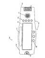
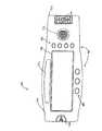
図5はハンドヘルドUPO500の一実施形態を図示している。ハンドヘルドUPO500はキーパッド入力510、LCDディスプレイ520、外部電源入力530、外部パルス酸素濃度計と接続するための出力ポート540、及び頂部面(図では見えない)のセンサ入力550を備える。ディスプレイ520は酸素飽和度測定値522、脈拍数測定値524、脈拍数即ち脈動事象と同期された脈動バー526、飽和度測定値及び脈拍数測定値の信頼度を示す信頼度バー528を表示する。また、電池の電力低下572、警告許可574の状況インジケータも表示される。 FIG. 5 illustrates one embodiment of a
図5を参照しながら説明されるハンドヘルド態様は、ハンドヘルドユニットを機械的に受け取り、それに電気的に接続されるドッキング・ステーションと共同して機能してもよい。ドッキング・ステーションは患者監視システムと同一場所に置くことができ、対応するSpO2モジュール・センサポート、外部電源、プリンタ、遠隔計測デバイス等のオプションに接続されることができる。この構成では、患者が第1の場所から第2の場所へ搬送される場合、ハンドヘルドUPOは第1のドッキング・ステーションから取り外され、搬送する間患者に随伴して連続的に監視を行う。第2の場所への到着後、ハンドヘルドUPOは第2のドッキング・ステーションに都合よく配置されることができ、UPO測定値はこの場所の患者監視システムで表示される。The handheld aspect described with reference to FIG. 5 may function in conjunction with a docking station that mechanically receives and electrically connects the handheld unit. The docking station can be co-located with the patient monitoring system and connected to options such as a corresponding SpO2 module sensor port, external power supply, printer, telemetry device, etc. In this configuration, when the patient is transported from the first location to the second location, the handheld UPO is removed from the first docking station and continuously monitored with the patient during transport. After arrival at the second location, the handheld UPO can be conveniently located at the second docking station and the UPO measurements are displayed on the patient monitoring system at this location.
図6は、UPO210の機能が可搬型パルス酸素濃度計610とドッキング・ステーション660との間で分割されている、UPOの一実施形態を示すブロック図である。可搬型パルス酸素濃度計610(以下「可搬部」)は電池で動作する、完全機能型のスタンドアロン・パルス酸素濃度測定機器である。可搬部610は、患者用ケーブル・コネクタ618に取り付けられたUPO患者用ケーブル220(図2参照)を介してセンサ110(図2参照)に接続されている。当該技術でよく知られているように、可搬部610は、センサの赤色LEDと赤外線LEDとを交互に起動する駆動信号612をセンサ110(図2参照)に供給する。また、可搬部は対応する検出部信号614をセンサから受信する。更に、本発明の譲受人に譲渡された米国特許第5,758,644号(「Manual and Automatic Probe Calibration」)(該特許を参照によって本明細書中に援用する)に開示されているように、可搬部は駆動信号ライン612上にセンサIDを入力することもできる。 FIG. 6 is a block diagram illustrating one embodiment of a UPO in which the functions of the
可搬部610は、ドッキング・ステーション660内に設置することにより、更に機能を広げることができる。可搬部610は、ドッキング・ステーション660内に設置されている間は、ドッキング・ステーション660が外部電源668に接続されていれば、ドッキング・ステーション660から電力を得ることができる。ドッキング・ステーション660が外部電源668と接続されていない場合、可搬部610は電力662をドッキング・ステーション660に供給することもできる。可搬部610は、二方向のシリアルデータライン664上でドッキング・ステーションと通信する。特に、可搬部610はセンサ検出部信号614より計算されるSpO2、脈拍数、関連するパラメータをドッキング・ステーションに提供する。可搬部610が設置されると、ドッキング・ステーション660は可搬部610の外部にあるホスト機器260(図2参照)を駆動することができる。或いは、図13に関連させて後述するように、可搬部610とドッキング・ステーション660とを組み合わせ、スタンドアロン・パルス酸素濃度測定機器として機能させることもできる。The
ある実施形態では、可搬部610がドッキングされていないときにはドッキング・ステーション660はいかなる動作も行わない。ドッキング・ステーション660用のユーザ・インタフェース(キーパッドやディスプレイ)は可搬部610側にある。可搬部がドッキングされると、ドッキング・ステーション660のインジケータLEDが点灯する。ドッキング・ステーション660は、ホスト機器からのLED駆動信号672、可搬部610から受信するSpO2値、及び関連するパラメータに応答し、ホスト機器260(図2参照)への検出器信号出力674を生成する。更に、ドッキング・ステーション660はシリアルデータ出力682、ナースコール684、アナログ出力688を行う。In some embodiments, the
ドッキング・ステーション660はインタフェース・ケーブル690を介してホスト機器の患者用ケーブル230(図2)に接続される。LED駆動信号672と検出部信号出力674とは、ドッキング・ステーション660とホスト機器260(図2参照)との間でインタフェース・ケーブル690を介して通信される。インタフェース・ケーブル690は、ドッキング・ステーション660への同期データ出力692、通信センサデータ、ホスト機器データ(例えば、図3に示すモニタID328)、及び較正曲線データを提供する。ドッキング・ステーション660がこのデータを用いて特定のホスト機器上に、患者の測定値を提供する特定のセンサとして現れるようにするとよい。 The
図7は可搬部610の更なる詳細を示している。可搬部の構成要素にはパルス酸素濃度測定プロセッサ710、管理プロセッサ720、電源730、ディスプレイ740、キーパッド750が含まれる。パルス酸素濃度測定プロセッサ710は、可搬部とセンサ110(図2参照)とのインタフェースとなり、SpO2、脈拍数、プレチスモグラフ及びパルスインジケータを導き出す、内部パルス酸素濃度計として機能する。パルス酸素濃度測定プロセッサ710として利用できる高度なパルス酸素濃度計が上で参照した米国特許第5,632,272号に開示されている。また、パルス酸素濃度測定プロセッサ710に取り付けるセンサ110(図2参照)として使用する高度なパルス酸素濃度測定センサが上で参照した米国特許第5,638,818号に開示されている。更に、高度なMasimo SET(登録商標)として展開されているパルス酸素濃度計のOEMボードやセンサが、本発明の譲受人から入手可能である。ある実施形態において、パルス酸素濃度測定プロセッサ710はMasimo SET(登録商標)MS-3Lボード、又は低出力のMS-5ボードを用いる。FIG. 7 shows further details of the
管理プロセッサ720は、パルス酸素濃度測定プロセッサ710との非同期シリアルデータ通信724、ドッキングステーション660(図6参照)との同期シリアル通信762を含む、可搬部のさまざまな機能を制御する。ドッキング・ステーション660(図6参照)との物理的接続はドッキング・ステーション・コネクタ763を介して、電気接続はドッキング・ステーション・インタフェース760を介して行われる。プロセッサ720は、傾向データを生成するためのSpO2パラメータと共に記憶された時間及び日付の情報を含む、リアルタイムクロック702を利用して、現在の日付及び時間を維持する。共通ルーチンを共用し、符号解明時間を最小化するため、可搬部610のプロセッサとドッキング・ステーション660(図6参照)とは同一系統のものとすることができる。The
更に、プロセッサ720は、データ742をディスプレイ更新及び視覚的警告を含むディスプレイ740に転送することにより、またキーパッド750からのキーストロークデータを解釈することにより、ユーザ・インタフェース800(図8A参照)を制御する。プロセッサ720は、スピーカ駆動部770を制御する許可信号728を通じて、必要に応じてさまざまな警告信号を発する。スピーカ駆動部770は、例えば警告やパルスビープ音等の可聴インジケータを発するスピーカ772を起動する。更に、プロセッサ720は電池残量を示す電池状態736、可搬部610のドッキング・ステーション660(図6参照)への接続の有無を示すドッキング状態764を含む、システム状態を監視する。可搬部610がドッキングされ、可搬部の電源がオンであるとき、プロセッサ720は更にドッキング・ステーションの電力732のターンオン及びターンオフを行う時期を決定する。 In addition, the
ドッキングされた可搬部610が、インタフェース・ケーブル690がドッキング・ステーション660をマルチパラメータ型患者監視システム等の外部パルス酸素濃度計に接続したことを感知したとき、加療者が可搬部のディスプレイ740の動作及び警告について設定(即ち、適合或いはプログラム)できるとよい。例えば、あるユーザ設定では、外部パルス酸素濃度計への接続が行われると、加療者は同一の値を患者監視システム上で見ることができるため、混乱を防ぐ目的で可搬部のディスプレイ740はSpO2値811及び脈拍数813(共に図8参照)の表示をストップする。このとき、ディスプレイ740はプレチスモグラフ815及び視覚的パルスインジケータ817(共に図8参照)の波形の表示は続けている。このようなユーザ設定を行うためには、可搬部の警告は起動状態にある。When the docked
プロセッサ720のもう1つのタスクに、ウオッチドッグ機能のメンテナンスがある。ウオッチドッグ780はウオッチドッグデータ入力782上でプロセッサ状態を監視し、故障が検出された場合にはμPリセット出力784を行使する。これにより管理プロセッサ720がリセットされ、可聴及び視覚的警告により故障が表示される。 Another task of the
可搬部610の電力は、電源730内の電池、又はドッキング・ステーション・インタフェース760を介してドッキング・ステーション660(図6参照)から供給される電力766より得られる。電力管理部790はキーパッド750上のオン/オフスイッチを監視し、監視結果に応じて可搬部の電源をオンにする。また、電力管理部790はプロセッサ720からのコマンドに従い可搬部の電源をオフにする。電源730のDC/DCコンバータは可搬部610及びドッキング・ステーション電力732の作動に必要とされる電圧738を発生する。可搬部の電池はアルカリ充電池やそれ以外の再生可能な電源とすることができる。ドッキング・ステーション660(図6参照)が外部電源に接続されていないときは、電源730の電池がドッキング・ステーション電力732を供給する。ドッキング・ステーション電源内の電池充電器は電源730内の充電式電池に充電電流768を供給する。ドッキング・ステーション電源990(図9参照)は充電式電池パックのサーミスタからの温度734を監視し、電池の充電状態を表示する。 The power of the
不揮発性メモリ706は高速バス722を介して管理プロセッサ720に接続されている。本実施形態では、メモリ706は、ブートデータ、製造通し番号、診断ミス履歴、成人のSpO2警告限度と脈拍数警告限度、新生児のSpO2警告限度と脈拍数警告限度、SpO2と脈拍数の傾向データ、及びプログラムデータを記憶させておく、消去可能型フィールド・リプログラマブル・デバイスである。この他のタイプの不揮発性メモリも知られている。SpO2に関連するアルゴリズムパラメータと同様に、SpO2警告限度と脈拍数警告限度は、可搬部610に接続されるセンサ110(図2参照)のタイプ、即ち成人用と新生児用の別に基づき、自動的に選択されることができる。The
LCDディスプレイ740は、コントラスト比を大きくし、また暗い環境下において視距離を拡大するため、バックライトにLEDを使用している。バックライトの強度は可搬部610用の電源により決定される。可搬部610が電源730内の電池パック或いはドッキング・ステーション電源990(図9参照)の電池パックから電力供給を受けている場合には、バックライトの強度は最低限である。可搬部610が外部電源668(図6参照)から電力供給を受けている場合には、視距離及び視角を拡大するため、バックライト強度はより高くなる。ある実施形態では、可搬部のボタンを押すことでこれらの強度設定を無効にすることができ、強度の調整を手動で行うことができる。バックライトの制御方法は2つある。可搬部をドッキングさせ、外部電源から電力供給を受ける場合を除き、何らかのキーを押すことでいつでもバックライトを一定の秒数間照明させ、その後オフとすることができる。可搬部がドッキングされ、外部電源から電力供給を受けている場合には、可搬部610のキーでオフにしない限り、バックライトは通常オンになっている。 The
図8Aはディスプレイ740、キーパッド750を含む、可搬部のユーザ・インタフェース800を示している。ある実施形態では、ディスプレイ740は160×480画素のドット・マトリクスLCDデバイスである。ディスプレイ740は、図8Bに示すような縦長表示や、図8Cに示すような横長表示が可能である。ドッキング・ステーション660(図6参照)のチルトセンサ950(図9参照)又は可搬部610(図6参照)のディスプレイ・モード・キーを用いて、縦長モード又は横長モードのいずれかを決定する。チルトセンサ950(図9参照)は重力により動作するスイッチ、或いは向きに反応する他のデバイスとすることができ、可搬部610(図6参照)側に配置することもできる。ある実施形態において、チルトセンサ950(図9参照)は、Comus International社(www.comus-intl.com)(所在地:米国ニュージャージー州、ナトリー)より部品番号CW 1300-1として市販されている非水銀チルトスイッチである。チルトセンサ950(図9参照)は水銀チルトスイッチとしてもよい。 FIG. 8A shows a portable user interface 800 including a
SpO2811、脈拍数813、プレチスモグラフ波形815、視覚的パルスインジケータ817、ソフトキーアイコン820を、縦長モード及び横長モードで表示する際のディスプレイ領域の使用例をそれぞれ図8B及び図8Cに示す。図8B及び図8Cに示される表示情報のカテゴリー、レイアウト、サイズを変更する際には、管理プロセッサ720(図7参照)のソフトウェアプログラムを容易に変更することができる。これらの他に表示できれば都合のよい情報として、SpO2限度値、警告、無効にされた警告、例外的なメッセージ、電池状態が挙げられる。FIGS. 8B and 8C show examples of the use of the display area when displaying
キーパッド750にはソフトキー870と固定キー880とがある。各固定キー880はそれぞれ固定された機能をもつ。各ソフトキー870の機能はプログラムすることができ、その機能はソフトキー870に近接するソフトキーアイコン820のうちの1つで表示することができる。即ち、特定のソフトキーアイコン820が特定のソフトキー870に近接する位置に配置されており、このアイコンはこのソフトキー870の機能を示す文又は形状を有する。ある実施形態では、キーパッド750の各キーのボタン部は蛍光物質で作られ、暗い環境下でもキー870、880が見やすくなっている。 The
一実施形態において、キーパッド750は4つのソフトキー870からなる列と、3つの固定キー880からなる列を一列ずつ有する。当然ながら、これ以外の構成も可能であるから、構成の如何は重要でない。3つの固定キー880の機能は電源、警告の消音、及び照明/コントラストである。電源機能はオン/オフのトグルボタンである。警告消音機能及び照明/コントラスト機能は、キーを押す時間によって変わる二重目的を有する。警告消音機能に相当するキーを瞬間的に押すと、可聴の警告を一定期間の間無効にする。可聴の警告を無期限に無効としたい場合には、警告消音機能に相当するキーをある程度長く押す。警告消音機能に相当するキーを可聴警告が聞こえなくなるまで押すと、可聴警告が再度オンとなる。照明/コントラスト機能に相当するキーを瞬間的に押す場合、このキーはバックライト用のオン/オフのトグルボタンである。照明/コントラスト機能に相当するキーを長く押すと、可能な値の範囲でディスプレイコントラストが循環する。 In one embodiment, the
本実施形態では、4つのソフトキー870のデフォルト機能はパルスビープ音の音量アップと音量ダウン、メニュー選択、及びディスプレイ・モード変換である。これらの機能は上向き矢印、下向き矢印、「メニュー」、曲り矢印で示すソフトキーアイコン820により、ディスプレイ上にそれぞれ表示されている。音量アップ及び音量ダウン機能は、検出される各パルスに関連する可聴音即ち「ビープ音」の大きさを増減させる。ディスプレイ・モード機能は、対応するキーを押す度に縦長モード(図8B参照)及び横長モード(図8C参照)を含む、直交する4つの向きを全て循環させる。メニュー選択機能により、ソフトキー870の機能性を上述したデフォルト機能から変更することができる。このメニュー特性を利用して選択することのできる付加的なソフトキー機能の例として、SpO2の上限及び下限の設定、脈拍数の上限及び下限の設定、警告音量の設定、傾向データの表示、印刷、消去の各設定、平均時間の設定、感度モードの設定、同期化の実行、充電池のメンテナンス(電池メモリを除去するための大規模な放電及び再充電)、製品の版番号の表示が挙げられる。In this embodiment, the default functions of the four
図9は、ドッキング・ステーション・プロセッサ910、不揮発性メモリ920、波形発生部930、PROMインタフェース940、チルトセンサ950、可搬部のインタフェース970及び関連するコネクタ972、状態インジケータ982、シリアルデータ・ポート682、ナースコール出力684、アナログ出力688及び電源990を含む、ドッキング・ステーション660を更に詳細に示したものである。ある実施形態では、ドッキング・ステーション660は、病院の救急治療室のマルチパラメータ患者監視機器等の固定された(可搬式でない)ホスト機器と関連されることを意図している。可搬式の実施形態では、ドッキング・ステーション660は移動可能であり、電源990内に電池パックを備えている。 FIG. 9 illustrates a
ドッキング・ステーション・プロセッサ910はドッキング・ステーション660の動作を統合する。プロセッサ910は図3及び図4に示すようなパラメータ932を波形発生部930に提供する。更に、プロセッサ910は、外部デバイスとの通信のための非同期シリアルデータ912、及び可搬部610(図6参照)との通信のための同期シリアルデータを提供する。また、プロセッサ910は、同期状態942、チルト状態952、及び電力状態992を含むシステム状態を決定する。可搬部管理プロセッサ720(図7参照)はドッキング・ステーション・プロセッサ910のためのウオッチドッグ機能を有する。ドッキング・ステーション・プロセッサ910の正確な動作を確実にするため、ドッキング・ステーション・プロセッサ910はウオッチドッグ・メッセージを同期シリアルデータ972の一部として可搬部プロセッサ720(図7参照)に送る。
ドッキング・ステーション・プロセッサ910は高速バス922を介して不揮発性メモリにアクセスする。不揮発性メモリはプログラム変更が可能であり、機器通信プロトコル、同期化情報、ブート画像、製造履歴、及び診断ミス履歴を含むプロセッサ910用のプログラム・データを含む。
波形発生部930は、図4に関して上述したように、SpO2値及び脈拍値を計算し例外的メッセージを表示するために従来技術のパルス酸素濃度計が処理することのできる同期波形を発生する。しかしながら、すでに述べたように、本実施形態では、波形発生部の出力は生理的波形を反映しない。即ち、外部パルス酸素濃度計が正確な飽和度及び脈拍数を計算することを可能とする、単なる波形である。これに代わる実施形態では、生理的データを外部パルス酸素濃度計に提供することはできるが、一般的に外部パルス濃度計は適切な飽和値を計算することができず、アップグレード特性が失われる。図10に関連して後述される、有効な同期化情報を有するインタフェース・ケーブル690(図6参照)が接続されると、波形発生部930に許可が与えられる。インタフェース・ケーブル690が接続されなければ、波形発生部930への電力供給は行われない。
状態インジケータ982は、外部電源(AC)、可搬部のドッキングの有無、可搬部の電池充電状態、ドッキング・ステーションの電池充電状態及び警告を含むさまざまな状況を表示するための、ドッキング・ステーション660の前部にある1組のLEDである。シリアルデータ・ポート682はコンピュータ、従来のパルス酸素濃度計のシリアル・ポート、シリアル・プリンタのいずれかを標準的なRS-232 DB-9コネクタ962を介してインタフェースで接続するために用いられる。このポート682は傾向メモリ、SpO2、脈拍数を出力することができ、さまざまな製造業者のシステム・プロトコルを支援する。アナログ出力688はコネクタ964を介してアナログ入力チャート・レコーダとインタフェースで接続するために用いられ、「実時間」又は傾向SpO2データ、脈拍数データを出力することができる。上限或いは下限を所定秒間連続して越えた場合、コネクタ964からのナースコール出力684が起動される。別の実施形態では、アップグレード用パルス酸素濃度計の遠隔利用を可能とするため、警告を含むデータを任意数の通信ポートに送ることができる。この場合インターネットの利用も可能である。
PROMインタフェース940は、インタフェース・ケーブル690(図6、図10参照)上でPROM1010(図10参照)からの同期化データ692にアクセスし、同期化状態942をドッキング・ステーション・プロセッサ910に送る。可搬部インタフェース970はドッキング・ステーション・インタフェース760(図7参照)を通じて可搬部610(図6参照)との相互接続を提供する。
図9に示されているように、標準的なACコネクタ968及びオン/オフスイッチ969を通じてドッキング・ステーション660に外部電力668が与えられる。ドッキング・ステーション660が外部電力668を有するとき、電源990は可搬部電源730(図7参照)の電池、及びドッキング・ステーションの電源990(ある場合)を充電する。可搬部610が取り外されている場合又は電源がオフの場合、ドッキング・ステーション電力973は供給されず、ドッキング・ステーション660は電源990の電池充電部を除いて電源オフとなる。ドッキングされた可搬部610(図6参照)の電源がオンであるときには常にドッキング・ステーション電源973がオンとなり、その結果ドッキング・ステーション660の電源もオンとなる。可搬部610(図6参照)は、外部電源668が取り外され或いは故障している場合、電池のないドッキング・ステーション660の一実施形態に電力を供給する。 As shown in FIG. 9,
図10はドッキング・ステーション660(図6参照)とホスト機器260(図2参照)の患者用ケーブル230(図2参照)との接続に用いられるインタフェース・ケーブル690を更に詳細に示したものである。インタフェース・ケーブル690は、特定のホスト機器にインタフェースで接続され、ホスト機器にとって特定のセンサとなるよう構成されている。インタフェース・ケーブル690に組み込まれたPROM1010は、センサのタイプ、特定のホスト機器、特定のホスト機器の較正曲線を識別する情報を含んでいる。PROM情報はドッキング・ステーション660(図6参照)により同期化データ692として読み出され得る。同期化データ692は、ドッキング・ステーション660(図6参照)がホスト機器に対し、可搬部610(図6参照)により計算されるものと同値のSpO2値をホスト機器に表示させる波形を発生させ得るものであるとよい。インタフェース・ケーブル690はLED駆動パス672を含む。図10に示された実施形態では、LED駆動パス672は共通陽極LED用に構成されており、IR陰極信号、レッド陰極信号、及び共通陽極信号を含む。インタフェース・ケーブル690は検出部陽極信号と検出部陰極信号とを含む、検出部駆動パス674を更に備える。FIG. 10 shows in more detail the
更に、可搬部610(図6参照)上のメニューオプションにより、同期化情報を現場で計算することが可能となる。手動で同期化することにより、ドッキング・ステーション660(図6参照)はホスト機器260(図2参照)に対し波形を発生し、SpO2の予期値を表示する。ユーザはホスト機器上に表示されたSpO2値を可搬部のキーパッド750(図7参照)を使って入力する。これらのステップは所定数のデータポイントが入力され、可搬部とホスト機器に表示されるSpO2値が同値となるまで反復される。Furthermore, the menu option on the portable unit 610 (see FIG. 6) allows the synchronization information to be calculated on site. By manually synchronizing, docking station 660 (see FIG. 6) generates a waveform to host device 260 (see FIG. 2) and displays the expected value of SpO2 . The user inputs the SpO2 value displayed on the host device using the keypad 750 (see FIG. 7) of the portable unit. These steps are repeated until a predetermined number of data points are input and the SpO2 values displayed on the portable unit and the host device are the same.
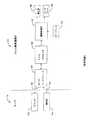
図11A及び図11Bは、図6に関連して上述した可搬部610の一実施形態を示したものである。図12A及び図12Bは図6に関連して上述したドッキング・ステーション660の一実施形態を示す。図13は、図6に関連して上述されているように、可搬部610がドッキング・ステーション660にドッキングされている、UPO210の一実施形態を示している。 11A and 11B show an embodiment of the
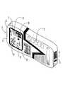
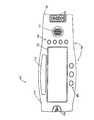
図11Aは可搬部の前部パネル1110を示す。可搬部610は図6に関連して上述した患者用ケーブル・コネクタ618を有する。コネクタ618は取り付けられる患者用ケーブル(図示せず)のストレスを最小化するよう、回転可能に取り付けられるとよい。ある実施形態では、コネクタ618は前部パネル1110に平行な平面と側部パネル1130に平行な平面との間で自在に旋回することができる。別の実施形態では、コネクタ618は3つの固定位置の間で旋回自在であり、取外し可能な状態に保持される。図示される如く、第1の固定位置はコネクタが前部パネル1110に平行な平面にある位置である。第2の固定位置はコネクタ618が側部パネル1130に平行な平面にある位置である。コネクタ618は第1の固定位置と第2の固定位置との間に、45°の中間固定位置を更に有する。コネクタ618はドッキング・ステーション660への取付け時には第1の位置に配置される。 FIG. 11A shows the
図11Aに示されるように、可搬部の前部パネル1110は更に図7に関連して上述したスピーカ772を有する。また、前部パネル1110には図8に関連して上述した一列のソフトキー870、及び固定キー880がある。更に、前部パネル1110は、ドッキング・ステーション660の対応するキャッチ1244(図12A参照)上に固定され、可搬部610がドッキング・ステーション660に取外し可能に保持されることを可能とする、指で起動するラッチ1120を有する。前部パネル1110の窪み部分1112にOEMラベルを貼付することができる。 As shown in FIG. 11A, the
図11Bは可搬部の背面パネル1140を示す。背面パネル1140にはソケット763、ポール・クランプ嵌合面1160、及び電池パック室1170がある。ソケット763は対応するドッキング・ステーション・プラグ972(図12A参照)と嵌合するよう構成されている。ソケット763とプラグ972(図12A参照)は可搬部610とドッキング・ステーション660(図12A参照)との間に電気接続インタフェースを提供する。ソケット763はドッキング・ステーション・プラグ972(図12A参照)のめっきを施したエッジコネクタ部を圧縮するマルチプルスプリング接触子を収容する。従来のポール・クランプ(図示せず)は嵌合面1160に着脱可能に取り付けることができる。これにより、可搬部610を患者の隣やベッドサイドのハンドフリー・パルス酸素濃度測定監視用のさまざまな取付位置に置くことが可能である。可搬部電源730(図7参照)は電池パック室1170内に収容される。電池パック室1170は、可搬部の電池パックの保護、電池の装填、取外しのための、着脱可能なカバー1172を備える。特定の可搬部を識別する通し番号等の製品ラベルを背面パネルのくぼみ1142に貼付することができる。 FIG. 11B shows the back panel 1140 of the portable part. The rear panel 1140 includes a
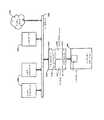
図12Aはドッキング・ステーション660の前部1210を示す。前部1210にはドッキング・コンパートメント1220、ポール・クランプ凹部1230、ピボット1242、キャッチ1244、プラグ・コネクタ972及びLED状態インジケータ982がある。図13に示すように、ドッキング・コンパートメント1220は可搬部610(図11A及び図11B参照)を受容し保持する。可搬部610(図11A及び図11B参照)がコンパートメント1220にドッキングされると、ポール・クランプ凹部1230が可搬部のポール・クランプ嵌合面1160(図11B参照)に取り付けられたポール・クランプ(図示せず)を収容し、ポール・クランプが閉位置にあると想定する。可搬部610(図11A及び図11B参照)は可搬部の側部面1130の対応する穴に嵌合されるピボット1242、及び可搬部のラッチ1120(図11A参照)と係合するキャッチ1244によりコンパートメント1220に保持される。従って、可搬部610(図11A及び図11B参照)はまずその一端をピボット1242に取り付け、ピボット1242を軸にして回転させることでコンパートメント1220にドッキングされる。可搬部610はコンパートメント1220のキャッチ1244上の位置に受容される。可搬部610(図11A及び図11B参照)はこの逆の手順により、即ちまず可搬部をキャッチ1244から取り外すためにラッチ1120(図11A参照)を押し、ピボット1242を軸にして可搬部610(図11A及び図11B参照)を回転させてコンパートメント1220から取り出し、ピボット1242から取り外すことにより、取り外される。可搬部が回転しながらコンパートメントに収容されるとき、ドッキング・ステーション・プラグ972が可搬部のソケット763(図11B参照)に挿入され、可搬部610とドッキング・ステーション660との間に電気的インタフェースを提供する。状態インジケータ982は図9に関連して上述した通りである。 FIG. 12A shows the front portion 1210 of the
図12Bはドッキング・ステーション660の背面1260を示す。背面1260にはシリアル(RS-232又はUSB)コネクタ962、アナログ出力及びナースコール・コネクタ964、アップグレード用ポート・コネクタ966、AC電力プラグ968、オン/オフスイッチ969及び接地ラグ1162がある。背面1260の一端にはハンドル1180が、他端にはファン孔1170が形成されている。背面1260の付近には1対の脚1190がある。これに対応する1対の脚(図示せず)が前面1210(図12A参照)の付近に形成されている。前面1210付近の脚は前面1210(図12A参照)を上向きに傾斜させるよう延出しており、これによりドッキングされた可搬部610(図13参照)のディスプレイ740(図13参照)が見やすくなっている。 FIG. 12B shows the back 1260 of the
図13は可搬部610及びドッキング・ステーション660の両方を図示している。可搬部610及びドッキング・ステーション660は3つの別々のパルス酸素濃度測定機器を構成している。第1に、図11A及び図11Bに示すように、可搬部610はそれ自体が救急車やER環境のように電池による電力とかなり自由な可搬性が必要とされる種々の患者監視タスクに適用することのできるハンドヘルド・パルス酸素濃度計である。第2に、図13に示すように、ドッキング・ステーション660にドッキングされた可搬部610は、病室から手術室のように広範にわたる典型的な患者監視環境に適用することのできるスタンドアロン・パルス酸素濃度計である。第3に、本明細書中に述べているように、可搬部610がドッキングされ、アップグレード用ポート966(図12B参照)が、マルチパラメータ患者監視機器260(図2参照)或いは他の一般的なパルス酸素濃度計内の一般的なパルス酸素濃度計モジュール268(図2参照)のセンサ・ポートにインタフェース・ケーブルを介して接続されているとき、可搬部610は汎用/アップグレード用パルス酸素濃度計(UPO)機器210である。従って、UPO210の可搬部610とドッキング・ステーション660の構成は、スリーインワンのパルス酸素濃度測定機器としての機能性を有するものが好ましい。 FIG. 13 illustrates both the
ドッキング・ステーション660の他の実施形態として、血圧センサに接続される入力ポート、及びマルチパラメータ型患者監視システム(MPMS)の血圧センサポートに接続される出力ポートを含むものがある。ドッキング・ステーション660は、血圧センサからの入力に基づいて血圧測定値を計算する信号プロセッサを含む。また、ドッキング・ステーション660は計算された測定値に基づいて同期化された波形を発生する出力ポートに接続された波形発生部を含む。波形発生部の出力は、MPMSに表示される血圧値が算出された血圧値と同値となるよう調整され得る。また、可搬部610がドッキング・ステーション660にドッキングされ、血圧センサが入力ポートに接続されると、可搬部は算出された血圧値に応じて血圧値を表示する。従って、本実施形態では、ドッキング・ステーション660は血圧とSpO2とに汎用/アップグレード用の能力を提供する。Other embodiments of
更に、ドッキング・ステーション660は、呼吸速度、心電図、脳波図等の他の生命徴候の測定のための汎用/アップグレード用機器として機能し得る。本実施形態では、ドッキング・ステーション660は、MPMSやスタンドアロン機器に接続される関連するセンサ・コネクタ、関連するセンサの信号プロセッサ、及びアップグレード用コネクタを含む。このようにすると、さまざまな生命徴候の測定値をドッキング・ステーション660に組み込むことができる。このとき、測定値は個別と組合せの如何を問わず、測定パラメータとしてのSpO2の有無を問わず、また可搬部610の使用の有無を問わない。更に別の実施形態では、ドッキング・ステーション660はSpO2プロセッサと、SpO2センサ用の患者用ケーブル・コネクタとを含む、可搬部610の有無に関わらず機能する1つのSpO2アップグレード用ボックスとして構成することもできる。In addition, the
従来技術のスタンドアロン・パルス酸素濃度計とは異なり、図13に示すようなスタンドアロン構成は、縦向き又は横向きで機器を作動させることのできる、回転可能なディスプレイ740を有する。チルトセンサ950(図9参照)は、底部面1310が水平面に沿って配置されている時、即ち水平の向きに置かれている時に表示を行う。この水平の向きにあるとき、ディスプレイ740は横長モード(図8C参照)にある。また、チルトセンサ950(図9参照)は側面1320が水平面に沿って配置されている時、即ち水平の向きに置かれている時に表示を行う。この垂直の向きにあるとき、ディスプレイ740は縦長モード(図8B参照)にある。可搬部610のソフトキー870によりチルトセンサの表示を無効にすることができ、ディスプレイをあらゆる90°の向き、即ち縦長、横長、上下を逆さにした縦長及び上下を逆さにした横長に配置することが可能である。ハンドヘルド構成(図11A参照)でもソフトキー870を用いてディスプレイ740をあらゆる90°の向きに配置することができる。但し、上に示した実施形態では、可搬部610はチルトセンサを備えておらず、従ってドッキングされていないときにはディスプレイの向きの変更はソフトキー870で行う。 Unlike prior art stand-alone pulse oximeters, a stand-alone configuration such as that shown in FIG. 13 has a
図14はローカル・エリア・ネットワーク(LAN)に組み込まれたドッキング・ステーション660を示している。ここに示すLANは、セントラルLANサーバ1420を利用して多くのLANクライアント1430、及びプリンタや記憶装置(図示せず)等の他のシステム・リソースを相互接続する、イーサネット(登録商標)・ベース1460である。イーサネット(登録商標)・コントローラ・モジュール1410はドッキング・ステーション660に組み込むことができる。コントローラ・モジュール1410はドッキング・ステーション660のハウジングに組み込んでもよく、また外部ユニットとして構成することも可能である。このようにすると、本発明のUPOはLAN又はインターネット1490を介して他のデバイスと通信することができる。 FIG. 14 shows a
イーサネット(登録商標)・コントローラ・モジュール1410はヒューレット・パッカード社(HP)のBFOOT-10501等のウェブ・サーバ・ファームウェアに組み込むことができる。モジュール1410は、イーサネット(登録商標)1460との接続用の10BASE-Tイーサネット(登録商標)・インタフェースと、ドッキング・ステーション660への接続用のRS-232又はUSB等のシリアル・インタフェースのとの両方を具備する。モジュール・ファームウェアはワールド・ワイド・ウェブを介した標準的な通信用のHTTP及びTCP/IPプロトコルを含む。ファームウェアは、遠隔クライアントが例えばインターネットを通じてカスタム・ウェブ・ページを閲覧できるようにする、マイクロ・ウェブ・サーバを更に含む。カスタムC++プログラミングによりデータ整理、事象検出及び動的ウェブ・ページ構成等のより広い能力が可能となる。 The
図14に示す如く、ドッキング・ステーション660からイーサネット(登録商標)・インタフェースへは数多くのアプリケーションがある。多数のUPOを病院のLANに接続することができ、またLANに接続されたコンピュータを使って多くのUPOから脈拍数や飽和度データをアップロードし、結果を表示させることができる。従って、このイーサネット(登録商標)・インタフェースを利用して病院内の中央パルス酸素濃度監視ステーションを実施することができる。更に、世界中のあらゆる場所にある多数のUPOをインターネットを通じて中央位置で監視することができる。各UPOは個々のウェブ・サイトとしてアドレス可能であり、標準的なブラウザで閲覧可能なウェブ・ページをダウンロードする。ウェブ・ページにはUPOからダウンロードされる酸素飽和度、脈拍数及び関連する生理的測定値が表示されている。この特徴により、加療者は患者の位置或いは加療者の位置に関わらず患者の監視を行うことができる。例えば、加療者がある都市の自宅又はある病院にいて、患者が別の都市の自宅或いは同じ又は別の病院にいる場合、加療者は患者の測定値をダウンロードすることができる。他のアプリケーションとして、新たに導入されたUPOのトラブルシューティング、ソフトウェアパッチのアップロード、インターネットを通じたUPOへのアップグレードが挙げられる。また、患者を監視している臨床医のURLに警告を送ることもできる。 As shown in FIG. 14, there are a number of applications from the
UPOは、図5に関連して述べたようなハンドヘルド・ユニットや、図11乃至図13に関連して述べたような可搬部610とドッキング・ステーション660の組合せの他にも種々に構成することができる。UPOはアームストラップ、ネックレス又は同様の手段により患者に着脱可能に固定することのできるモジュールとすることもできる。このときディスプレイの有無は問わない。更に小型の実施形態では、このUPOモジュールはセンサをパルス酸素濃度計に取り付ける際に用いるケーブル又はコネクタに一体的に組み込むこともできる。また、UPOはスタンドアロン・パルス酸素濃度計又はマルチパラメータ型患者監視システムに外部又は内部より差し込み或いは嵌め込むことのできる、回路カード又はモジュールとすることもできる。或いは、UPOは単純なスタンドアロン・アップグレード用機器として構成してもよい。 The UPO may be variously configured in addition to the handheld unit as described with reference to FIG. 5 and the combination of the
汎用/アップグレード用装置及び方法を主にパルス酸素濃度測定器としての態様に関して説明してきたが、本発明は例えば血圧、呼吸速度、脳波図、心電図等、他の生理的測定パラメータにも同様に適用することが可能である。また、生理的測定パラメータを1つのみ扱うもの、多数の測定パラメータ能力を有するもの、そして例えばハンドヘルド、スタンドアロン、可搬型、ドッキング・ステーション、モジュール、プラグイン、回路カードとして構成される汎用/アップグレード用機器も、本発明の範囲に含まれる。 Although the general purpose / upgrade device and method have been described primarily with respect to the embodiment as a pulse oximeter, the invention is equally applicable to other physiological measurement parameters such as blood pressure, respiratory rate, electroencephalogram, electrocardiogram, etc. Is possible. For general purpose / upgrades that handle only one physiological measurement parameter, have multiple measurement parameter capabilities, and are configured as handheld, stand-alone, portable, docking station, module, plug-in, circuit card, for example Equipment is also included within the scope of the present invention.
本発明の多様な実施形態に関連させ、UPOを詳細に開示した。これらの実施形態は実施例を挙げて開示したが、これらは請求の範囲で定義される本発明の範囲を限定するものではない。当業者であれば、本発明の範囲内で多くの変更や修正を行うことは可能であろう。 The UPO has been disclosed in detail in connection with various embodiments of the present invention. While these embodiments have been disclosed by way of examples, they are not intended to limit the scope of the invention as defined in the claims. Those skilled in the art will be able to make many changes and modifications within the scope of the present invention.
210 汎用/アップグレード用パルス酸素濃度計(UPO)
660、910 可搬型ユニット(610)とドッキング・ステーション
320、930 波形発生部210 General purpose / upgrade pulse oximeter (UPO)
660, 910 Portable unit (610) and
Claims (47)
Translated fromJapaneseポータブル生理的測定装置であって、第1のローカル・ディスプレイと第1のプロセッサを備え、該第1のプロセッサは、1つ以上の生理的パラメータの値を決定するために測定データを処理するように構成され、該ポータブル生理的測定装置は、ポータブル・モードで作動することができ、該ポータブル・モードは、1つ以上のセンサとの通信を通して患者の該1つ以上の生理的パラメータのスタンドアロン・ユニットとしてポータブル監視を提供し、該ポータブル生理的測定装置は、ドッキング・モードで作動することができ、該ドッキング・モードは患者の1つ以上の生理的パラメータの監視を提供する、該ポータブル生理的測定装置と、
ドッキング・ステーションであって、前記ポータブル生理的測定装置と組み合わされたときに患者監視装置を形成し、該ドッキング・ステーションは、前記ポータブル生理的測定装置から得られた測定データ以外の測定データを少なくとも処理することによって追加の生理的パラメータを測定するように構成され、該ドッキング・ステーションは、前記ポータブル生理的測定装置が少なくとも前記ドッキング・モードで作動するとき前記ポータブル生理的測定装置と嵌合するように構成された、該ドッキング・ステーションと、
を備え、
前記ポータブル生理的測定装置は、前記ドッキング・ステーションと電気的通信をし、
前記ドッキング・ステーションは、第2のローカル・ディスプレイと電気通信をし、
ドッキング・ステーション・プロセッサは、前記ドッキング・ステーションと関連付けられている
ことを特徴とする前記システム。A system for monitoring at least one physiological condition of a patient,
A portable physiological measurement device comprising a first local display and a first processor, wherein the first processor is adapted to process measurement data to determine values of one or more physiological parameters. The portable physiological measurement device can be operated in a portable mode, wherein the portable mode is a stand-alone device for the one or more physiological parameters of a patient through communication with one or more sensors. Providing portable monitoring as a unit, wherein the portable physiological measurement device can operate in a docking mode, wherein the docking mode provides monitoring of one or more physiological parameters of a patient A measuring device;
A docking station forming a patient monitoring device when combined with the portable physiological measurement device, the docking station at least receiving measurement data other than the measurement data obtained from the portable physiological measurement device; Configured to measure an additional physiological parameter by processing, wherein the docking station is adapted to mate with the portable physiological measuring device when the portable physiological measuring device operates at least in the docking mode. The docking station configured to:
With
The portable physiological measurement device is in electrical communication with the docking station;
The docking station is in electrical communication with a second local display;
The system of claim 1, wherein a docking station processor is associated with the docking station.
請求項1の前記システム。The system of claim 1, wherein the patient monitoring device is in communication with a display device.
スタンドアロン患者監視システムを形成するドッキング・ステーションから物理的及び電気的に離隔されたポータブル測定器で、1つ以上の生理的パラメータの値を得るために、第1の生理的測定を実行するステップであって、該ドッキング・ステーションは、前記ポータブル生理的測定器が少なくとも前記ドッキング・モードで作動するとき前記ポータブル測定器と嵌合するように構成され、前記ポータブル生理的測定装置は、前記ドッキング・ステーションと電気的通信をし、前記ドッキング・ステーションは、第2のローカル・ディスプレイと電気通信をし、前記ドッキング・ステーションは、ドッキング・ステーション・プロセッサと関連付けられている、該ステップと、
前記スタンドアロン器の表示部上に、前記第1の測定に関連する情報を提供するステップと、
前記ドッキング・ステーションと嵌合された前記ポータブル測定器で、第2の生理的測定を実行するステップと、
前記ドッキング・ステーションに前記第2の生理的測定を送信するステップと、
第3の生理的測定を実行するステップであって、該第3の生理的測定は、前記スタンドアロン器に利用可能でない測定データを処理する、該ステップと、
前記ドッキング・ステーションと通信する監視器上に、前記第2及び第3の測定に関連する情報を提供するステップと、
を備えた前記方法。A patient monitoring method using a portable measuring instrument,
Performing a first physiological measurement to obtain a value of one or more physiological parameters with a portable instrument physically and electrically separated from a docking station forming a stand-alone patient monitoring system; And wherein the docking station is configured to mate with the portable meter when the portable meter is operating at least in the docking mode, the portable meter is configured to be connected to the docking station. In electrical communication with, the docking station in electrical communication with a second local display, the docking station being associated with a docking station processor;
Providing on the display of the stand-alone device information related to the first measurement;
Performing a second physiological measurement with the portable meter fitted with the docking station;
Transmitting the second physiological measurement to the docking station;
Performing a third physiological measurement, wherein the third physiological measurement processes measurement data not available to the stand-alone device;
Providing information related to the second and third measurements on a monitor in communication with the docking station;
Said method comprising.
ポータブル生理的測定装置であって、該ポータブル生理的測定装置は、第1のローカル・ディスプレイと第1のプロセッサを備え、該第1のプロセッサは、1つ以上の生理的パラメータの値を決定するために測定データを処理するように構成され、該ポータブル生理的測定装置は、ポータブル・モードで作動することができ、該ポータブル・モードは、1つ以上のセンサとの通信を通して患者の該1つ以上の生理的パラメータのスタンドアロン・ユニットとしてポータブル監視を提供し、該ポータブル生理的測定装置は、統合モードで作動することができ、該統合モードは患者の1つ以上の生理的パラメータの統合監視を提供する、該ポータブル生理的測定装置と、
ドッキング・ステーションであって、該ドッキング・ステーションは、患者監視装置を形成し、前記ポータブル生理的測定装置からの信号以外の信号を少なくとも処理することによって生理的パラメータを測定するように構成され、該ドッキング・ステーションは、前記ポータブル生理的測定装置が少なくとも前記統合モードで作動するとき前記ポータブル生理的測定装置と嵌合するように構成された該ドッキング・ステーションと、
を備え、
前記ポータブル生理的測定装置は、前記ドッキング・ステーションと電気的通信をし、
前記ドッキング・ステーションは、第2のローカル・ディスプレイと電気通信をし、
ドッキング・ステーション・プロセッサは、前記ドッキング・ステーションと関連付けられている
ことを特徴とする前記システム。A system for monitoring at least one physiological condition of a patient,
A portable physiological measurement device comprising a first local display and a first processor, wherein the first processor determines a value of one or more physiological parameters. The portable physiological measurement device is capable of operating in a portable mode, wherein the portable mode is configured to process the one of the patient through communication with one or more sensors. Providing portable monitoring as a stand-alone unit of the above physiological parameters, the portable physiological measurement device can operate in an integrated mode, which provides integrated monitoring of one or more physiological parameters of a patient. Providing the portable physiological measurement device;
A docking station configured to form a patient monitoring device and measure a physiological parameter by processing at least a signal other than the signal from the portable physiological measurement device; A docking station configured to mate with the portable physiological measurement device when the portable physiological measurement device operates at least in the integrated mode;
With
The portable physiological measurement device is in electrical communication with the docking station;
The docking station is in electrical communication with a second local display;
The system of claim 1, wherein a docking station processor is associated with the docking station.
ディスプレイと、
第1の生理的センサからの生理的情報を受け取るための1つ以上の入力と、
前記生理的情報を用いて第1の生理的測定を決定するように構成されたポータブル監視プロセッサと、
ドッキング・ステーションとドッキングするように構成されたドッキング部材であって、該ドッキング・ステーションは、第2の生理的センサと通信するように構成され、該ドッキング・ステーションは、該ドッキング・ステーションに関連付けられたドッキング・ステーション・プロセッサを含み、前記ドッキング・ステーション・プロセッサは、少なくとも前記第2の生理的センサに応答する第2の生理的測定を決定するように構成された、該ドッキング部材と、
1つ以上の通信部であって、該通信部は、前記ドッキング・ステーションが、ローカル・ディスプレイと通信する場所で、前記ドッキング・ステーション・プロセッサと通信すると共に前記第2の生理的測定を示す情報を受け取るように、構成された、該通信部と、
を備え、
前記ポータブル監視プロセッサは、ポータブル・モードで作動することが可能であり、該ポータブル・モードは、スタンドアロン・ユニットとしてポータブル監視を提供し、前記ポータブル監視プロセッサは、ドッキング・モードで作動することが可能であり、該ドッキング・モードは、前記1つ以上の出力からの生理的情報を前記ドッキング・ステーション・プロセッサに送信しかつ患者の1つ以上の生理的パラメータの監視を提供する
ことを特徴とする前記スタンドアロン・ポータブル生理的監視器。A stand-alone portable physiological monitor that can be docked with a docking station,
Display,
One or more inputs for receiving physiological information from the first physiological sensor;
A portable monitoring processor configured to determine a first physiological measurement using the physiological information;
A docking member configured to dock with a docking station, the docking station configured to communicate with a second physiological sensor, the docking station associated with the docking station A docking station processor, the docking station processor configured to determine a second physiological measurement responsive to at least the second physiological sensor; and
One or more communication units, wherein the communication unit communicates with the docking station processor and indicates the second physiological measurement at a location where the docking station communicates with a local display. The communication unit configured to receive
With
The portable monitoring processor can operate in a portable mode, which provides portable monitoring as a stand-alone unit, and the portable monitoring processor can operate in a docking mode. And wherein the docking mode transmits physiological information from the one or more outputs to the docking station processor and provides for monitoring of one or more physiological parameters of the patient. Stand-alone portable physiological monitor.
ポータブル生理的測定装置であって、該ポータブル生理的測定装置は、第1のローカル・ディスプレイを備え、ポータブル・モードで作動することができ、該ポータブル・モードは、1つ以上のセンサとの通信を通して患者の該1つ以上の生理的パラメータのスタンドアロン・ユニットとしてポータブル監視を提供し、該ポータブル生理的測定装置は、ドッキング・モードで作動することができ、該ドッキング・モードは患者の1つ以上の生理的パラメータの監視を提供する、該ポータブル生理的測定装置と、
ドッキング・ステーションであって、該ドッキング・ステーションは、前記ポータブル生理的測定装置と組み合わされたときに患者監視システムを形成し、該ドッキング・ステーションは、前記ポータブル生理的測定装置が少なくとも前記ドッキング・モードで作動するとき前記ポータブル生理的測定装置と嵌合するように構成された、該ドッキング・ステーションと、
を備え、
前記ポータブル生理的測定装置は、前記ドッキング・ステーションと電気的通信をし、
前記ドッキング・ステーションは、第2のローカル・ディスプレイと電気通信をする
ことを特徴とする患者監視システム。A patient monitoring system,
A portable physiological measurement device comprising a first local display and capable of operating in a portable mode, wherein the portable mode is in communication with one or more sensors. Providing portable monitoring as a stand-alone unit of the one or more physiological parameters of the patient through which the portable physiological measurement device can operate in a docking mode, the docking mode being one or more of the patient The portable physiological measurement device providing monitoring of physiological parameters of
A docking station that, when combined with the portable physiological measurement device, forms a patient monitoring system, the docking station comprising at least the docking mode of the portable physiological measurement device; The docking station configured to mate with the portable physiological measurement device when operated at
With
The portable physiological measurement device is in electrical communication with the docking station;
The patient monitoring system, wherein the docking station is in electrical communication with a second local display.
スタンドアロン患者監視システムを形成するドッキング・ステーションから物理的及び電気的に離隔されたポータブル測定器で、第1の生理的測定を実行するステップであって、該ドッキング・ステーションは、前記ポータブル生理的測定器が少なくとも前記ドッキング・モードで作動するとき前記ポータブル測定器と嵌合するように構成され、前記ポータブル生理的測定装置は、前記ドッキング・ステーションと電気的通信をし、前記ドッキング・ステーションは、第2のローカル・ディスプレイと電気通信をし、前記スタンドアロン器の表示部上に、前記第1の測定に関連する情報を提供する、該ステップと、
前記ドッキング・ステーションと嵌合された前記ポータブル測定器で第2の生理的測定を実行するステップと、
前記ドッキング・ステーションに前記第2の生理的測定を送信するステップと、
前記ドッキング・ステーションと通信する監視器上に、前記第2の測定に関連する情報を提供するステップと、
を有する前記方法。A patient monitoring method using a portable measuring instrument,
Performing a first physiological measurement with a portable instrument physically and electrically separated from a docking station forming a stand-alone patient monitoring system, the docking station comprising said portable physiological measurement; Configured to mate with the portable meter at least when operating in the docking mode, wherein the portable physiological measurement device is in electrical communication with the docking station, the docking station comprising: Telecommunications with two local displays and providing information related to the first measurement on a display of the stand-alone device;
Performing a second physiological measurement with the portable meter fitted with the docking station;
Transmitting the second physiological measurement to the docking station;
Providing information related to the second measurement on a monitor in communication with the docking station;
Said method comprising:
外部測定装置の第2のセンサポートに接続することのできるアップグレード用ポートと、
前記第1のセンサポートへの信号入力に基づいて測定値を計算する信号プロセッサと、
前記測定値に応答して合成された信号を発生する信号発生部であって、前記合成された信号が前記アップグレード用ポートに供給され、前記アップグレード用ポートが前記第2のセンサポートに取り付けられているとき、前記合成された信号は前記外部測定装置が前記測定値と略同一の値を計算することができるよう発生される信号発生部とを備える測定器。A first sensor port that can be connected to the sensor;
An upgrade port that can be connected to the second sensor port of the external measuring device;
A signal processor for calculating a measurement based on a signal input to the first sensor port;
A signal generator for generating a synthesized signal in response to the measurement value, wherein the synthesized signal is supplied to the upgrade port, and the upgrade port is attached to the second sensor port; And a signal generator that generates the synthesized signal so that the external measuring device can calculate a value substantially equal to the measured value.
前記酸素飽和度測定値及び前記脈拍数測定値に基づいて波形信号を発生する手段と、
前記波形信号を第2のパルス酸素濃度計に伝送する手段とを備える測定器。A first pulse oximeter configured to determine an oxygen saturation measurement and a pulse rate measurement based on an intensity signal obtained from a tissue site;
Means for generating a waveform signal based on the oxygen saturation measurement and the pulse rate measurement;
Means for transmitting said waveform signal to a second pulse oximeter.
前記可搬部を収容し、前記可搬部と通信するよう構成されたドッキング・ステーションとを備え、
前記可搬部が、前記可搬部と前記ドッキング・ステーションとを組み合わせることで前記可搬部の機能に少なくとも1つの機能を追加する、前記ドッキング・ステーションとのドッキング位置を有する、測定器。A portable unit comprising a sensor port, a processor, and a display, wherein the sensor port is configured to receive a signal indicative of a physiological parameter, and the processor calculates a physiological parameter measurement based on the intensity signal A portable portion programmed to output the physiological parameter measurements to the display, the portable portion configured to operate as a handheld physiological monitor;
A docking station configured to house the portable portion and to communicate with the portable portion;
A measuring instrument, wherein the portable unit has a docking position with the docking station that adds at least one function to the function of the portable unit by combining the portable unit and the docking station.
重力に感応して出力を行うチルトセンサと、
第1のモードと第2のモードとを有するディスプレイであって、前記ディスプレイが前記チルトセンサに応答して、前記装置が前記第1の配置の向きにあるときには第1のモードで動作し、前記装置が第2の配置の向きにあるときには第2のモードで動作し、前記第1及び第2のモードが前記ディスプレイ上のデータの向きを制御している、ディスプレイとを備える測定器。A measuring instrument configured to function in both the orientation of the first arrangement and the orientation of the second arrangement,
A tilt sensor that outputs in response to gravity;
A display having a first mode and a second mode, wherein the display is responsive to the tilt sensor and operates in the first mode when the device is in the first orientation; A meter comprising: a display that operates in a second mode when the device is in a second orientation, wherein the first and second modes control the orientation of data on the display.
生理学的状態に応答する信号を受け取るよう構成されたセンサポートと、
前記センサポート及び前記チルトセンサ出力と通信するプロセッサとを更に備え、前記プロセッサが、前記信号に基づいて生理的測定値を計算し、前記チルトセンサの出力に基づいて前記測定装置が第1の配置の向きにあるか、第2の配置の向きにあるかを決定し、前記第1モードまたは前記第2モードでディスプレイを駆動するようプログラムされている、請求項42に記載の測定器。A measuring instrument, wherein the measuring instrument is a physiological monitor,
A sensor port configured to receive a signal responsive to a physiological condition;
And a processor in communication with the sensor port and the tilt sensor output, wherein the processor calculates a physiological measurement based on the signal, and the measurement device has a first arrangement based on the output of the tilt sensor. 43. The instrument of claim 42, programmed to determine whether the orientation is in a second orientation or a second orientation and drive the display in the first mode or the second mode.
Applications Claiming Priority (4)
| Application Number | Priority Date | Filing Date | Title |
|---|---|---|---|
| US11709799P | 1999-01-25 | 1999-01-25 | |
| US60/117,097 | 1999-01-25 | ||
| US16156599P | 1999-10-26 | 1999-10-26 | |
| US60/161,565 | 1999-10-26 |
Related Parent Applications (1)
| Application Number | Title | Priority Date | Filing Date |
|---|---|---|---|
| JP2000594379ADivisionJP4986324B2 (en) | 1999-01-25 | 2000-01-25 | General purpose / upgrade pulse oximeter |
Related Child Applications (1)
| Application Number | Title | Priority Date | Filing Date |
|---|---|---|---|
| JP2010228371ADivisionJP5443318B2 (en) | 1999-01-25 | 2010-10-08 | General purpose / upgrade pulse oximeter |
Publications (2)
| Publication Number | Publication Date |
|---|---|
| JP2010012335Atrue JP2010012335A (en) | 2010-01-21 |
| JP4987057B2 JP4987057B2 (en) | 2012-07-25 |
Family
ID=26814906
Family Applications (4)
| Application Number | Title | Priority Date | Filing Date |
|---|---|---|---|
| JP2000594379AExpired - LifetimeJP4986324B2 (en) | 1999-01-25 | 2000-01-25 | General purpose / upgrade pulse oximeter |
| JP2009242957AExpired - LifetimeJP4987057B2 (en) | 1999-01-25 | 2009-10-22 | General purpose / upgrade pulse oximeter |
| JP2010228371AExpired - Fee RelatedJP5443318B2 (en) | 1999-01-25 | 2010-10-08 | General purpose / upgrade pulse oximeter |
| JP2013235585APendingJP2014064929A (en) | 1999-01-25 | 2013-11-14 | Universal/upgrading pulse oximeter |
Family Applications Before (1)
| Application Number | Title | Priority Date | Filing Date |
|---|---|---|---|
| JP2000594379AExpired - LifetimeJP4986324B2 (en) | 1999-01-25 | 2000-01-25 | General purpose / upgrade pulse oximeter |
Family Applications After (2)
| Application Number | Title | Priority Date | Filing Date |
|---|---|---|---|
| JP2010228371AExpired - Fee RelatedJP5443318B2 (en) | 1999-01-25 | 2010-10-08 | General purpose / upgrade pulse oximeter |
| JP2013235585APendingJP2014064929A (en) | 1999-01-25 | 2013-11-14 | Universal/upgrading pulse oximeter |
Country Status (8)
| Country | Link |
|---|---|
| US (1) | US6584336B1 (en) |
| EP (2) | EP1148809B1 (en) |
| JP (4) | JP4986324B2 (en) |
| AT (1) | ATE378001T1 (en) |
| AU (1) | AU2859600A (en) |
| CA (2) | CA2358454C (en) |
| DE (1) | DE60037106T2 (en) |
| WO (1) | WO2000042911A1 (en) |
Cited By (35)
| Publication number | Priority date | Publication date | Assignee | Title |
|---|---|---|---|---|
| JP2011152261A (en)* | 2010-01-27 | 2011-08-11 | Nippon Koden Corp | Portable biological signal measuring/transmission system |
| JP2013039375A (en)* | 2011-08-16 | 2013-02-28 | Ethicon Endo Surgery Inc | Docking station for patient bedside monitoring unit |
| JP2014504893A (en)* | 2010-10-28 | 2014-02-27 | エンハンスド サーフェイス ダイナミクス,インコーポレイテッド | Pressure sensor assembly and related methods for avoiding the development of pressure ulcers |
| US9513177B2 (en) | 2010-03-12 | 2016-12-06 | Enhanced Surface Dynamics, Inc. | System and method for rapid data collection from pressure sensors in a pressure sensing system |
| US9671304B2 (en) | 2011-07-13 | 2017-06-06 | Enhanced Surface Dynamics, Inc. | Methods and systems for the manufacture and initiation of a pressure detection mat |
| JP2017529880A (en)* | 2014-05-30 | 2017-10-12 | アップル インコーポレイテッド | Health data aggregator |
| JP2018138169A (en)* | 2018-03-30 | 2018-09-06 | アップル インコーポレイテッド | Presentation of physiologic data |
| US10492734B2 (en) | 2016-11-04 | 2019-12-03 | Wellsense, Inc. | Patient visualization system |
| US10635267B2 (en) | 2017-05-15 | 2020-04-28 | Apple Inc. | Displaying a scrollable list of affordances associated with physical activities |
| US10674942B2 (en) | 2018-05-07 | 2020-06-09 | Apple Inc. | Displaying user interfaces associated with physical activities |
| US10736543B2 (en) | 2016-09-22 | 2020-08-11 | Apple Inc. | Workout monitor interface |
| US10777314B1 (en) | 2019-05-06 | 2020-09-15 | Apple Inc. | Activity trends and workouts |
| US10802703B2 (en) | 2015-03-08 | 2020-10-13 | Apple Inc. | Sharing user-configurable graphical constructs |
| US10873786B2 (en) | 2016-06-12 | 2020-12-22 | Apple Inc. | Recording and broadcasting application visual output |
| US10877720B2 (en) | 2015-06-07 | 2020-12-29 | Apple Inc. | Browser with docked tabs |
| US10953307B2 (en) | 2018-09-28 | 2021-03-23 | Apple Inc. | Swim tracking and notifications for wearable devices |
| US10978195B2 (en) | 2014-09-02 | 2021-04-13 | Apple Inc. | Physical activity and workout monitor |
| US11019193B2 (en) | 2015-02-02 | 2021-05-25 | Apple Inc. | Device, method, and graphical user interface for establishing a relationship and connection between two devices |
| US11083418B2 (en) | 2016-11-04 | 2021-08-10 | Wellsense, Inc. | Patient visualization system |
| US11107580B1 (en) | 2020-06-02 | 2021-08-31 | Apple Inc. | User interfaces for health applications |
| US11148007B2 (en) | 2016-06-11 | 2021-10-19 | Apple Inc. | Activity and workout updates |
| US11152100B2 (en) | 2019-06-01 | 2021-10-19 | Apple Inc. | Health application user interfaces |
| US11216119B2 (en) | 2016-06-12 | 2022-01-04 | Apple Inc. | Displaying a predetermined view of an application |
| US11277485B2 (en) | 2019-06-01 | 2022-03-15 | Apple Inc. | Multi-modal activity tracking user interface |
| US11317833B2 (en) | 2018-05-07 | 2022-05-03 | Apple Inc. | Displaying user interfaces associated with physical activities |
| US11430571B2 (en) | 2014-05-30 | 2022-08-30 | Apple Inc. | Wellness aggregator |
| US11446548B2 (en) | 2020-02-14 | 2022-09-20 | Apple Inc. | User interfaces for workout content |
| US11539831B2 (en) | 2013-03-15 | 2022-12-27 | Apple Inc. | Providing remote interactions with host device using a wireless device |
| US11580867B2 (en) | 2015-08-20 | 2023-02-14 | Apple Inc. | Exercised-based watch face and complications |
| US11782575B2 (en) | 2018-05-07 | 2023-10-10 | Apple Inc. | User interfaces for sharing contextually relevant media content |
| US11896871B2 (en) | 2022-06-05 | 2024-02-13 | Apple Inc. | User interfaces for physical activity information |
| US11931625B2 (en) | 2021-05-15 | 2024-03-19 | Apple Inc. | User interfaces for group workouts |
| US11977729B2 (en) | 2022-06-05 | 2024-05-07 | Apple Inc. | Physical activity information user interfaces |
| US11996190B2 (en) | 2013-12-04 | 2024-05-28 | Apple Inc. | Wellness aggregator |
| US12080421B2 (en) | 2013-12-04 | 2024-09-03 | Apple Inc. | Wellness aggregator |
Families Citing this family (589)
| Publication number | Priority date | Publication date | Assignee | Title |
|---|---|---|---|---|
| MX9702434A (en)* | 1991-03-07 | 1998-05-31 | Masimo Corp | Signal processing apparatus. |
| EP1357481A3 (en)* | 1991-03-07 | 2005-04-27 | Masimo Corporation | Signal processing apparatus and method |
| US5490505A (en) | 1991-03-07 | 1996-02-13 | Masimo Corporation | Signal processing apparatus |
| US5638818A (en)* | 1991-03-21 | 1997-06-17 | Masimo Corporation | Low noise optical probe |
| US6662033B2 (en)* | 1994-04-01 | 2003-12-09 | Nellcor Incorporated | Pulse oximeter and sensor optimized for low saturation |
| US6371921B1 (en)* | 1994-04-15 | 2002-04-16 | Masimo Corporation | System and method of determining whether to recalibrate a blood pressure monitor |
| EP1905352B1 (en) | 1994-10-07 | 2014-07-16 | Masimo Corporation | Signal processing method |
| US8019400B2 (en) | 1994-10-07 | 2011-09-13 | Masimo Corporation | Signal processing apparatus |
| US6931268B1 (en) | 1995-06-07 | 2005-08-16 | Masimo Laboratories, Inc. | Active pulse blood constituent monitoring |
| US5758644A (en)* | 1995-06-07 | 1998-06-02 | Masimo Corporation | Manual and automatic probe calibration |
| US6517283B2 (en) | 2001-01-16 | 2003-02-11 | Donald Edward Coffey | Cascading chute drainage system |
| US6027452A (en)* | 1996-06-26 | 2000-02-22 | Vital Insite, Inc. | Rapid non-invasive blood pressure measuring device |
| US6018673A (en) | 1996-10-10 | 2000-01-25 | Nellcor Puritan Bennett Incorporated | Motion compatible sensor for non-invasive optical blood analysis |
| US6229856B1 (en) | 1997-04-14 | 2001-05-08 | Masimo Corporation | Method and apparatus for demodulating signals in a pulse oximetry system |
| US6002952A (en) | 1997-04-14 | 1999-12-14 | Masimo Corporation | Signal processing apparatus and method |
| US6525386B1 (en)* | 1998-03-10 | 2003-02-25 | Masimo Corporation | Non-protruding optoelectronic lens |
| CA2333062A1 (en) | 1998-06-03 | 1999-12-09 | Mohamed K. Diab | Stereo pulse oximeter |
| USRE41912E1 (en) | 1998-10-15 | 2010-11-02 | Masimo Corporation | Reusable pulse oximeter probe and disposable bandage apparatus |
| US7245953B1 (en) | 1999-04-12 | 2007-07-17 | Masimo Corporation | Reusable pulse oximeter probe and disposable bandage apparatii |
| US6684091B2 (en)* | 1998-10-15 | 2004-01-27 | Sensidyne, Inc. | Reusable pulse oximeter probe and disposable bandage method |
| US6721585B1 (en) | 1998-10-15 | 2004-04-13 | Sensidyne, Inc. | Universal modular pulse oximeter probe for use with reusable and disposable patient attachment devices |
| US6463311B1 (en)* | 1998-12-30 | 2002-10-08 | Masimo Corporation | Plethysmograph pulse recognition processor |
| US6684090B2 (en) | 1999-01-07 | 2004-01-27 | Masimo Corporation | Pulse oximetry data confidence indicator |
| US6770028B1 (en) | 1999-01-25 | 2004-08-03 | Masimo Corporation | Dual-mode pulse oximeter |
| US6658276B2 (en) | 1999-01-25 | 2003-12-02 | Masimo Corporation | Pulse oximeter user interface |
| ATE378001T1 (en) | 1999-01-25 | 2007-11-15 | Masimo Corp | UNIVERSAL/UPGRADING PULSE OXIMETER |
| US20020140675A1 (en) | 1999-01-25 | 2002-10-03 | Ali Ammar Al | System and method for altering a display mode based on a gravity-responsive sensor |
| US6360114B1 (en) | 1999-03-25 | 2002-03-19 | Masimo Corporation | Pulse oximeter probe-off detector |
| US6675031B1 (en) | 1999-04-14 | 2004-01-06 | Mallinckrodt Inc. | Method and circuit for indicating quality and accuracy of physiological measurements |
| US6515273B2 (en)* | 1999-08-26 | 2003-02-04 | Masimo Corporation | System for indicating the expiration of the useful operating life of a pulse oximetry sensor |
| US6708049B1 (en)* | 1999-09-28 | 2004-03-16 | Nellcor Puritan Bennett Incorporated | Sensor with signature of data relating to sensor |
| US6950687B2 (en) | 1999-12-09 | 2005-09-27 | Masimo Corporation | Isolation and communication element for a resposable pulse oximetry sensor |
| US6377829B1 (en)* | 1999-12-09 | 2002-04-23 | Masimo Corporation | Resposable pulse oximetry sensor |
| EP1274343B1 (en) | 2000-04-17 | 2012-08-15 | Nellcor Puritan Bennett LLC | Pulse oximeter sensor with piece-wise function |
| US8224412B2 (en) | 2000-04-17 | 2012-07-17 | Nellcor Puritan Bennett Llc | Pulse oximeter sensor with piece-wise function |
| US6430525B1 (en) | 2000-06-05 | 2002-08-06 | Masimo Corporation | Variable mode averager |
| US7689437B1 (en)* | 2000-06-16 | 2010-03-30 | Bodymedia, Inc. | System for monitoring health, wellness and fitness |
| US6640116B2 (en)* | 2000-08-18 | 2003-10-28 | Masimo Corporation | Optical spectroscopy pathlength measurement system |
| DE60139128D1 (en) | 2000-08-18 | 2009-08-13 | Masimo Corp | PULSE OXIMETER WITH TWO OPERATING MODES |
| WO2002034129A1 (en)* | 2000-10-24 | 2002-05-02 | Optovent Ab | Capacity stress testing method and apparatus |
| AU2002226956A1 (en) | 2000-11-22 | 2002-06-03 | Leap Wireless International, Inc. | Method and system for providing interactive services over a wireless communications network |
| ES2278818T3 (en) | 2000-11-23 | 2007-08-16 | Sentec Ag | SENSOR AND PROCEDURE FOR MEASURING PHYSIOLOGICAL PARAMETERS. |
| US6760610B2 (en) | 2000-11-23 | 2004-07-06 | Sentec Ag | Sensor and method for measurement of physiological parameters |
| RU2218075C2 (en)* | 2001-01-09 | 2003-12-10 | Наумов Валерий Аркадьевич | Method and device for recording and processing plethysmogram data to measure human cardiovascular system parameters |
| US6985764B2 (en) | 2001-05-03 | 2006-01-10 | Masimo Corporation | Flex circuit shielded optical sensor |
| JP2003028791A (en)* | 2001-05-09 | 2003-01-29 | Olympus Optical Co Ltd | Optical imaging device |
| US20020188181A1 (en)* | 2001-06-07 | 2002-12-12 | Boit Christopher S. | Interface for a portable point-of-care patient diagnostic device |
| DE20109864U1 (en)* | 2001-06-13 | 2001-08-30 | REHAU AG + Co., 95111 Rehau | Integrated cable adapter |
| US6850787B2 (en) | 2001-06-29 | 2005-02-01 | Masimo Laboratories, Inc. | Signal component processor |
| US6697658B2 (en) | 2001-07-02 | 2004-02-24 | Masimo Corporation | Low power pulse oximeter |
| US7040318B2 (en) | 2001-07-30 | 2006-05-09 | Imt Medical Ag | Ventilator |
| US6748254B2 (en) | 2001-10-12 | 2004-06-08 | Nellcor Puritan Bennett Incorporated | Stacked adhesive optical sensor |
| US6701170B2 (en) | 2001-11-02 | 2004-03-02 | Nellcor Puritan Bennett Incorporated | Blind source separation of pulse oximetry signals |
| US20030212312A1 (en)* | 2002-01-07 | 2003-11-13 | Coffin James P. | Low noise patient cable |
| US6934570B2 (en)* | 2002-01-08 | 2005-08-23 | Masimo Corporation | Physiological sensor combination |
| US6822564B2 (en)* | 2002-01-24 | 2004-11-23 | Masimo Corporation | Parallel measurement alarm processor |
| US7355512B1 (en) | 2002-01-24 | 2008-04-08 | Masimo Corporation | Parallel alarm processor |
| WO2003065557A2 (en)* | 2002-01-25 | 2003-08-07 | Masimo Corporation | Power supply rail controller |
| US10173008B2 (en) | 2002-01-29 | 2019-01-08 | Baxter International Inc. | System and method for communicating with a dialysis machine through a network |
| US8775196B2 (en) | 2002-01-29 | 2014-07-08 | Baxter International Inc. | System and method for notification and escalation of medical data |
| US20030149593A1 (en)* | 2002-02-04 | 2003-08-07 | Msc Healthcare (S) Pte. Ltd. | Health-care system |
| WO2003071939A1 (en)* | 2002-02-22 | 2003-09-04 | Masimo Corporation | Active pulse spectraphotometry |
| US7509494B2 (en)* | 2002-03-01 | 2009-03-24 | Masimo Corporation | Interface cable |
| US6863652B2 (en)* | 2002-03-13 | 2005-03-08 | Draeger Medical Systems, Inc. | Power conserving adaptive control system for generating signal in portable medical devices |
| US6850788B2 (en) | 2002-03-25 | 2005-02-01 | Masimo Corporation | Physiological measurement communications adapter |
| US6792396B2 (en) | 2002-03-28 | 2004-09-14 | Ge Medical Systems Information Technologies, Inc. | Interface device and method for a monitoring network |
| US8234128B2 (en) | 2002-04-30 | 2012-07-31 | Baxter International, Inc. | System and method for verifying medical device operational parameters |
| US6997905B2 (en)* | 2002-06-14 | 2006-02-14 | Baxter International Inc. | Dual orientation display for a medical device |
| US7018361B2 (en) | 2002-06-14 | 2006-03-28 | Baxter International Inc. | Infusion pump |
| US7096054B2 (en)* | 2002-08-01 | 2006-08-22 | Masimo Corporation | Low noise optical housing |
| US7558892B2 (en)* | 2002-08-08 | 2009-07-07 | Agere Systems Inc. | Processing device peripheral with integral network interface circuitry |
| US7627354B2 (en)* | 2002-08-30 | 2009-12-01 | Qualcomm Incorporated | Display format for handheld wireless communication devices |
| SE523545C2 (en)* | 2002-09-19 | 2004-04-27 | Foss Tecator Ab | Method, a portable device and a measuring instrument for standardizing a satellite measuring instrument to a corresponding main measuring instrument |
| US7274955B2 (en)* | 2002-09-25 | 2007-09-25 | Masimo Corporation | Parameter compensated pulse oximeter |
| US7142901B2 (en)* | 2002-09-25 | 2006-11-28 | Masimo Corporation | Parameter compensated physiological monitor |
| US7096052B2 (en)* | 2002-10-04 | 2006-08-22 | Masimo Corporation | Optical probe including predetermined emission wavelength based on patient type |
| WO2004034898A2 (en)* | 2002-10-15 | 2004-04-29 | Philips Intellectual Property & Standards Gmbh | Method for the presentation of information concerning variations of the perfusion |
| US7190986B1 (en) | 2002-10-18 | 2007-03-13 | Nellcor Puritan Bennett Inc. | Non-adhesive oximeter sensor for sensitive skin |
| US7027849B2 (en) | 2002-11-22 | 2006-04-11 | Masimo Laboratories, Inc. | Blood parameter measurement system |
| US6970792B1 (en) | 2002-12-04 | 2005-11-29 | Masimo Laboratories, Inc. | Systems and methods for determining blood oxygen saturation values using complex number encoding |
| US7919713B2 (en) | 2007-04-16 | 2011-04-05 | Masimo Corporation | Low noise oximetry cable including conductive cords |
| US7225006B2 (en) | 2003-01-23 | 2007-05-29 | Masimo Corporation | Attachment and optical probe |
| US6920345B2 (en) | 2003-01-24 | 2005-07-19 | Masimo Corporation | Optical sensor including disposable and reusable elements |
| US6954664B2 (en)* | 2003-06-20 | 2005-10-11 | Smiths Medical Pm, Inc. | Oximetry simulator |
| US20050055276A1 (en)* | 2003-06-26 | 2005-03-10 | Kiani Massi E. | Sensor incentive method |
| US7003338B2 (en) | 2003-07-08 | 2006-02-21 | Masimo Corporation | Method and apparatus for reducing coupling between signals |
| US7500950B2 (en)* | 2003-07-25 | 2009-03-10 | Masimo Corporation | Multipurpose sensor port |
| US7254431B2 (en)* | 2003-08-28 | 2007-08-07 | Masimo Corporation | Physiological parameter tracking system |
| US7254434B2 (en)* | 2003-10-14 | 2007-08-07 | Masimo Corporation | Variable pressure reusable sensor |
| US7483729B2 (en) | 2003-11-05 | 2009-01-27 | Masimo Corporation | Pulse oximeter access apparatus and method |
| US7373193B2 (en)* | 2003-11-07 | 2008-05-13 | Masimo Corporation | Pulse oximetry data capture system |
| US20050113655A1 (en)* | 2003-11-26 | 2005-05-26 | Hull Drue A. | Wireless pulse oximeter configured for web serving, remote patient monitoring and method of operation |
| JP4751338B2 (en)* | 2003-12-30 | 2011-08-17 | ユニバーシティ オブ フロリダ リサーチファウンデーション インコーポレイティッド | New and specially configured nasal pulse oximeter |
| US7280858B2 (en)* | 2004-01-05 | 2007-10-09 | Masimo Corporation | Pulse oximetry sensor |
| US7371981B2 (en)* | 2004-02-20 | 2008-05-13 | Masimo Corporation | Connector switch |
| US7162288B2 (en) | 2004-02-25 | 2007-01-09 | Nellcor Purtain Bennett Incorporated | Techniques for detecting heart pulses and reducing power consumption in sensors |
| US7190985B2 (en)* | 2004-02-25 | 2007-03-13 | Nellcor Puritan Bennett Inc. | Oximeter ambient light cancellation |
| US7438683B2 (en) | 2004-03-04 | 2008-10-21 | Masimo Corporation | Application identification sensor |
| US7534212B2 (en) | 2004-03-08 | 2009-05-19 | Nellcor Puritan Bennett Llc | Pulse oximeter with alternate heart-rate determination |
| WO2005087097A1 (en) | 2004-03-08 | 2005-09-22 | Masimo Corporation | Physiological parameter system |
| US20050234317A1 (en)* | 2004-03-19 | 2005-10-20 | Kiani Massi E | Low power and personal pulse oximetry systems |
| WO2005096922A1 (en)* | 2004-03-31 | 2005-10-20 | Masimo Corporation | Physiological assessment system |
| US20050228244A1 (en)* | 2004-04-07 | 2005-10-13 | Triage Wireless, Inc. | Small-scale, vital-signs monitoring device, system and method |
| CA2464029A1 (en) | 2004-04-08 | 2005-10-08 | Valery Telfort | Non-invasive ventilation monitor |
| US7343186B2 (en) | 2004-07-07 | 2008-03-11 | Masimo Laboratories, Inc. | Multi-wavelength physiological monitor |
| US9341565B2 (en) | 2004-07-07 | 2016-05-17 | Masimo Corporation | Multiple-wavelength physiological monitor |
| US7937128B2 (en)* | 2004-07-09 | 2011-05-03 | Masimo Corporation | Cyanotic infant sensor |
| EP1781162A1 (en)* | 2004-07-09 | 2007-05-09 | Tadiran Spectralink Ltd. | Wearable device, system and method for measuring vital parameters |
| US7254429B2 (en) | 2004-08-11 | 2007-08-07 | Glucolight Corporation | Method and apparatus for monitoring glucose levels in a biological tissue |
| US8036727B2 (en) | 2004-08-11 | 2011-10-11 | Glt Acquisition Corp. | Methods for noninvasively measuring analyte levels in a subject |
| US7976472B2 (en) | 2004-09-07 | 2011-07-12 | Masimo Corporation | Noninvasive hypovolemia monitor |
| WO2006039350A1 (en)* | 2004-09-29 | 2006-04-13 | Masimo Corporation | Multiple key position plug |
| DE102004061541B4 (en)* | 2004-12-21 | 2007-11-29 | Aipermon Gmbh & Co. Kg | System for connecting mobile measuring devices to data acquisition devices |
| AU2006204886B2 (en) | 2005-01-13 | 2011-08-04 | Welch Allyn, Inc. | Vital signs monitor |
| US7392074B2 (en)* | 2005-01-21 | 2008-06-24 | Nonin Medical, Inc. | Sensor system with memory and method of using same |
| USD566282S1 (en) | 2005-02-18 | 2008-04-08 | Masimo Corporation | Stand for a portable patient monitor |
| USD554263S1 (en) | 2005-02-18 | 2007-10-30 | Masimo Corporation | Portable patient monitor |
| US20060189871A1 (en) | 2005-02-18 | 2006-08-24 | Ammar Al-Ali | Portable patient monitor |
| US7647083B2 (en) | 2005-03-01 | 2010-01-12 | Masimo Laboratories, Inc. | Multiple wavelength sensor equalization |
| US7937129B2 (en)* | 2005-03-21 | 2011-05-03 | Masimo Corporation | Variable aperture sensor |
| WO2006110859A2 (en) | 2005-04-13 | 2006-10-19 | Glucolight Corporation | Method for data reduction and calibration of an oct-based blood glucose monitor |
| US20060287589A1 (en)* | 2005-06-16 | 2006-12-21 | James Wobermin | Digital photoplethysmographic signal sensor |
| JP2007000445A (en)* | 2005-06-24 | 2007-01-11 | Ngk Spark Plug Co Ltd | Breathing state monitoring device and breathing state monitoring system |
| US12014328B2 (en) | 2005-07-13 | 2024-06-18 | Vccb Holdings, Inc. | Medicine bottle cap with electronic embedded curved display |
| JP4710084B2 (en)* | 2005-07-15 | 2011-06-29 | コニカミノルタセンシング株式会社 | Biological information measuring device |
| US7657295B2 (en) | 2005-08-08 | 2010-02-02 | Nellcor Puritan Bennett Llc | Medical sensor and technique for using the same |
| US7657294B2 (en) | 2005-08-08 | 2010-02-02 | Nellcor Puritan Bennett Llc | Compliant diaphragm medical sensor and technique for using the same |
| US7590439B2 (en) | 2005-08-08 | 2009-09-15 | Nellcor Puritan Bennett Llc | Bi-stable medical sensor and technique for using the same |
| US20070073116A1 (en)* | 2005-08-17 | 2007-03-29 | Kiani Massi E | Patient identification using physiological sensor |
| EP1758039A1 (en)* | 2005-08-27 | 2007-02-28 | Roche Diagnostics GmbH | Communication adaptor for portable medical or therapeutical devices |
| US20070060808A1 (en) | 2005-09-12 | 2007-03-15 | Carine Hoarau | Medical sensor for reducing motion artifacts and technique for using the same |
| US7725146B2 (en)* | 2005-09-29 | 2010-05-25 | Nellcor Puritan Bennett Llc | System and method for pre-processing waveforms |
| US7725147B2 (en) | 2005-09-29 | 2010-05-25 | Nellcor Puritan Bennett Llc | System and method for removing artifacts from waveforms |
| US8092379B2 (en) | 2005-09-29 | 2012-01-10 | Nellcor Puritan Bennett Llc | Method and system for determining when to reposition a physiological sensor |
| US7869850B2 (en) | 2005-09-29 | 2011-01-11 | Nellcor Puritan Bennett Llc | Medical sensor for reducing motion artifacts and technique for using the same |
| US7904130B2 (en) | 2005-09-29 | 2011-03-08 | Nellcor Puritan Bennett Llc | Medical sensor and technique for using the same |
| US7899510B2 (en) | 2005-09-29 | 2011-03-01 | Nellcor Puritan Bennett Llc | Medical sensor and technique for using the same |
| US7881762B2 (en) | 2005-09-30 | 2011-02-01 | Nellcor Puritan Bennett Llc | Clip-style medical sensor and technique for using the same |
| US7486979B2 (en) | 2005-09-30 | 2009-02-03 | Nellcor Puritan Bennett Llc | Optically aligned pulse oximetry sensor and technique for using the same |
| US7483731B2 (en) | 2005-09-30 | 2009-01-27 | Nellcor Puritan Bennett Llc | Medical sensor and technique for using the same |
| US8233954B2 (en) | 2005-09-30 | 2012-07-31 | Nellcor Puritan Bennett Llc | Mucosal sensor for the assessment of tissue and blood constituents and technique for using the same |
| US7555327B2 (en) | 2005-09-30 | 2009-06-30 | Nellcor Puritan Bennett Llc | Folding medical sensor and technique for using the same |
| US8062221B2 (en) | 2005-09-30 | 2011-11-22 | Nellcor Puritan Bennett Llc | Sensor for tissue gas detection and technique for using the same |
| US7962188B2 (en) | 2005-10-14 | 2011-06-14 | Masimo Corporation | Robust alarm system |
| US7530942B1 (en) | 2005-10-18 | 2009-05-12 | Masimo Corporation | Remote sensing infant warmer |
| WO2007064984A2 (en) | 2005-11-29 | 2007-06-07 | Masimo Corporation | Optical sensor including disposable and reusable elements |
| US7990382B2 (en)* | 2006-01-03 | 2011-08-02 | Masimo Corporation | Virtual display |
| US8182443B1 (en) | 2006-01-17 | 2012-05-22 | Masimo Corporation | Drug administration controller |
| US7806337B2 (en) | 2006-02-06 | 2010-10-05 | Draeger Medical Systems, Inc. | System for managing memory storing data in one or more wireless transceiver devices |
| US20070244377A1 (en)* | 2006-03-14 | 2007-10-18 | Cozad Jenny L | Pulse oximeter sleeve |
| US8219172B2 (en) | 2006-03-17 | 2012-07-10 | Glt Acquisition Corp. | System and method for creating a stable optical interface |
| US7758203B2 (en)* | 2006-04-03 | 2010-07-20 | Welch Allyn, Inc. | Power connections and interface for compact illuminator assembly |
| US8770482B2 (en)* | 2006-04-26 | 2014-07-08 | Roche Diagnostics Operations, Inc. | Apparatus and method to administer and manage an intelligent base unit for a handheld medical device |
| US7522948B2 (en) | 2006-05-02 | 2009-04-21 | Nellcor Puritan Bennett Llc | Medical sensor and technique for using the same |
| US8073518B2 (en) | 2006-05-02 | 2011-12-06 | Nellcor Puritan Bennett Llc | Clip-style medical sensor and technique for using the same |
| US7477924B2 (en) | 2006-05-02 | 2009-01-13 | Nellcor Puritan Bennett Llc | Medical sensor and technique for using the same |
| US8998809B2 (en) | 2006-05-15 | 2015-04-07 | Cercacor Laboratories, Inc. | Systems and methods for calibrating minimally invasive and non-invasive physiological sensor devices |
| US9176141B2 (en) | 2006-05-15 | 2015-11-03 | Cercacor Laboratories, Inc. | Physiological monitor calibration system |
| US7941199B2 (en) | 2006-05-15 | 2011-05-10 | Masimo Laboratories, Inc. | Sepsis monitor |
| WO2007140478A2 (en) | 2006-05-31 | 2007-12-06 | Masimo Corporation | Respiratory monitoring |
| US10188348B2 (en) | 2006-06-05 | 2019-01-29 | Masimo Corporation | Parameter upgrade system |
| US20070284114A1 (en) | 2006-06-08 | 2007-12-13 | Halliburton Energy Services, Inc. | Method for removing a consumable downhole tool |
| US20080257549A1 (en) | 2006-06-08 | 2008-10-23 | Halliburton Energy Services, Inc. | Consumable Downhole Tools |
| US7591318B2 (en) | 2006-07-20 | 2009-09-22 | Halliburton Energy Services, Inc. | Method for removing a sealing plug from a well |
| CN100571625C (en)* | 2006-08-07 | 2009-12-23 | 北京超思电子技术有限责任公司 | A kind of checking refers to press from both sides the method for oximeter measurement data and refer to press from both sides oximeter |
| US8145288B2 (en) | 2006-08-22 | 2012-03-27 | Nellcor Puritan Bennett Llc | Medical sensor for reducing signal artifacts and technique for using the same |
| US8315683B2 (en)* | 2006-09-20 | 2012-11-20 | Masimo Corporation | Duo connector patient cable |
| US8457707B2 (en) | 2006-09-20 | 2013-06-04 | Masimo Corporation | Congenital heart disease monitor |
| USD609193S1 (en) | 2007-10-12 | 2010-02-02 | Masimo Corporation | Connector assembly |
| USD614305S1 (en) | 2008-02-29 | 2010-04-20 | Masimo Corporation | Connector assembly |
| US8219170B2 (en) | 2006-09-20 | 2012-07-10 | Nellcor Puritan Bennett Llc | System and method for practicing spectrophotometry using light emitting nanostructure devices |
| USD587657S1 (en) | 2007-10-12 | 2009-03-03 | Masimo Corporation | Connector assembly |
| US8840549B2 (en) | 2006-09-22 | 2014-09-23 | Masimo Corporation | Modular patient monitor |
| US8175671B2 (en) | 2006-09-22 | 2012-05-08 | Nellcor Puritan Bennett Llc | Medical sensor for reducing signal artifacts and technique for using the same |
| US8195264B2 (en) | 2006-09-22 | 2012-06-05 | Nellcor Puritan Bennett Llc | Medical sensor for reducing signal artifacts and technique for using the same |
| US9161696B2 (en) | 2006-09-22 | 2015-10-20 | Masimo Corporation | Modular patient monitor |
| US8396527B2 (en) | 2006-09-22 | 2013-03-12 | Covidien Lp | Medical sensor for reducing signal artifacts and technique for using the same |
| US20080103375A1 (en)* | 2006-09-22 | 2008-05-01 | Kiani Massi E | Patient monitor user interface |
| US7869849B2 (en) | 2006-09-26 | 2011-01-11 | Nellcor Puritan Bennett Llc | Opaque, electrically nonconductive region on a medical sensor |
| US8123695B2 (en)* | 2006-09-27 | 2012-02-28 | Nellcor Puritan Bennett Llc | Method and apparatus for detection of venous pulsation |
| US7574245B2 (en) | 2006-09-27 | 2009-08-11 | Nellcor Puritan Bennett Llc | Flexible medical sensor enclosure |
| US7890153B2 (en) | 2006-09-28 | 2011-02-15 | Nellcor Puritan Bennett Llc | System and method for mitigating interference in pulse oximetry |
| US7796403B2 (en) | 2006-09-28 | 2010-09-14 | Nellcor Puritan Bennett Llc | Means for mechanical registration and mechanical-electrical coupling of a faraday shield to a photodetector and an electrical circuit |
| US7476131B2 (en) | 2006-09-29 | 2009-01-13 | Nellcor Puritan Bennett Llc | Device for reducing crosstalk |
| US7680522B2 (en) | 2006-09-29 | 2010-03-16 | Nellcor Puritan Bennett Llc | Method and apparatus for detecting misapplied sensors |
| US7684842B2 (en) | 2006-09-29 | 2010-03-23 | Nellcor Puritan Bennett Llc | System and method for preventing sensor misuse |
| US8068891B2 (en) | 2006-09-29 | 2011-11-29 | Nellcor Puritan Bennett Llc | Symmetric LED array for pulse oximetry |
| US8175667B2 (en) | 2006-09-29 | 2012-05-08 | Nellcor Puritan Bennett Llc | Symmetric LED array for pulse oximetry |
| US7880626B2 (en) | 2006-10-12 | 2011-02-01 | Masimo Corporation | System and method for monitoring the life of a physiological sensor |
| EP2073692B1 (en) | 2006-10-12 | 2017-07-26 | Masimo Corporation | Perfusion index smoothing |
| US9192329B2 (en) | 2006-10-12 | 2015-11-24 | Masimo Corporation | Variable mode pulse indicator |
| US9861305B1 (en) | 2006-10-12 | 2018-01-09 | Masimo Corporation | Method and apparatus for calibration to reduce coupling between signals in a measurement system |
| US8255026B1 (en) | 2006-10-12 | 2012-08-28 | Masimo Corporation, Inc. | Patient monitor capable of monitoring the quality of attached probes and accessories |
| US8265723B1 (en) | 2006-10-12 | 2012-09-11 | Cercacor Laboratories, Inc. | Oximeter probe off indicator defining probe off space |
| US20080094228A1 (en)* | 2006-10-12 | 2008-04-24 | Welch James P | Patient monitor using radio frequency identification tags |
| US8052618B2 (en)* | 2006-10-15 | 2011-11-08 | Roche Diagnostics Operations, Inc. | Diagnostic test element and process for its production |
| US8600467B2 (en) | 2006-11-29 | 2013-12-03 | Cercacor Laboratories, Inc. | Optical sensor including disposable and reusable elements |
| JP5441707B2 (en) | 2006-12-09 | 2014-03-12 | マシモ コーポレイション | Plethysmograph variation processor |
| US7791155B2 (en)* | 2006-12-22 | 2010-09-07 | Masimo Laboratories, Inc. | Detector shield |
| US8852094B2 (en) | 2006-12-22 | 2014-10-07 | Masimo Corporation | Physiological parameter system |
| US8652060B2 (en)* | 2007-01-20 | 2014-02-18 | Masimo Corporation | Perfusion trend indicator |
| US20080202764A1 (en)* | 2007-02-22 | 2008-08-28 | Halliburton Energy Services, Inc. | Consumable downhole tools |
| US7894869B2 (en) | 2007-03-09 | 2011-02-22 | Nellcor Puritan Bennett Llc | Multiple configuration medical sensor and technique for using the same |
| US8280469B2 (en) | 2007-03-09 | 2012-10-02 | Nellcor Puritan Bennett Llc | Method for detection of aberrant tissue spectra |
| US8229530B2 (en)* | 2007-03-09 | 2012-07-24 | Nellcor Puritan Bennett Llc | System and method for detection of venous pulsation |
| US8109882B2 (en) | 2007-03-09 | 2012-02-07 | Nellcor Puritan Bennett Llc | System and method for venous pulsation detection using near infrared wavelengths |
| US8221326B2 (en)* | 2007-03-09 | 2012-07-17 | Nellcor Puritan Bennett Llc | Detection of oximetry sensor sites based on waveform characteristics |
| US8265724B2 (en) | 2007-03-09 | 2012-09-11 | Nellcor Puritan Bennett Llc | Cancellation of light shunting |
| EP2139383B1 (en) | 2007-03-27 | 2013-02-13 | Masimo Laboratories, Inc. | Multiple wavelength optical sensor |
| US8374665B2 (en) | 2007-04-21 | 2013-02-12 | Cercacor Laboratories, Inc. | Tissue profile wellness monitor |
| WO2008154643A1 (en) | 2007-06-12 | 2008-12-18 | Triage Wireless, Inc. | Vital sign monitor for measuring blood pressure using optical, electrical, and pressure waveforms |
| US12245852B2 (en) | 2007-06-12 | 2025-03-11 | Sotera Wireless, Inc. | Optical sensors for use in vital sign monitoring |
| US11607152B2 (en) | 2007-06-12 | 2023-03-21 | Sotera Wireless, Inc. | Optical sensors for use in vital sign monitoring |
| US8602997B2 (en) | 2007-06-12 | 2013-12-10 | Sotera Wireless, Inc. | Body-worn system for measuring continuous non-invasive blood pressure (cNIBP) |
| US11330988B2 (en) | 2007-06-12 | 2022-05-17 | Sotera Wireless, Inc. | Body-worn system for measuring continuous non-invasive blood pressure (cNIBP) |
| US8764671B2 (en) | 2007-06-28 | 2014-07-01 | Masimo Corporation | Disposable active pulse sensor |
| US7857222B2 (en) | 2007-08-16 | 2010-12-28 | Hand Held Products, Inc. | Data collection system having EIR terminal interface node |
| US8048040B2 (en) | 2007-09-13 | 2011-11-01 | Masimo Corporation | Fluid titration system |
| WO2009049101A1 (en) | 2007-10-12 | 2009-04-16 | Masimo Corporation | Connector assembly |
| US8310336B2 (en) | 2008-10-10 | 2012-11-13 | Masimo Corporation | Systems and methods for storing, analyzing, retrieving and displaying streaming medical data |
| US8355766B2 (en)* | 2007-10-12 | 2013-01-15 | Masimo Corporation | Ceramic emitter substrate |
| WO2009049254A2 (en) | 2007-10-12 | 2009-04-16 | Masimo Corporation | Systems and methods for storing, analyzing, and retrieving medical data |
| MX338871B (en)* | 2007-12-10 | 2016-05-04 | Bayer Healthcare Llc | Interface for a health measurement and monitoring system. |
| US8352004B2 (en) | 2007-12-21 | 2013-01-08 | Covidien Lp | Medical sensor and technique for using the same |
| US8346328B2 (en) | 2007-12-21 | 2013-01-01 | Covidien Lp | Medical sensor and technique for using the same |
| US8366613B2 (en) | 2007-12-26 | 2013-02-05 | Covidien Lp | LED drive circuit for pulse oximetry and method for using same |
| US8577434B2 (en) | 2007-12-27 | 2013-11-05 | Covidien Lp | Coaxial LED light sources |
| US8452364B2 (en) | 2007-12-28 | 2013-05-28 | Covidien LLP | System and method for attaching a sensor to a patient's skin |
| US8442608B2 (en) | 2007-12-28 | 2013-05-14 | Covidien Lp | System and method for estimating physiological parameters by deconvolving artifacts |
| US8092993B2 (en) | 2007-12-31 | 2012-01-10 | Nellcor Puritan Bennett Llc | Hydrogel thin film for use as a biosensor |
| US8070508B2 (en) | 2007-12-31 | 2011-12-06 | Nellcor Puritan Bennett Llc | Method and apparatus for aligning and securing a cable strain relief |
| US8897850B2 (en) | 2007-12-31 | 2014-11-25 | Covidien Lp | Sensor with integrated living hinge and spring |
| US8199007B2 (en) | 2007-12-31 | 2012-06-12 | Nellcor Puritan Bennett Llc | Flex circuit snap track for a biometric sensor |
| US8750953B2 (en)* | 2008-02-19 | 2014-06-10 | Covidien Lp | Methods and systems for alerting practitioners to physiological conditions |
| US8571617B2 (en) | 2008-03-04 | 2013-10-29 | Glt Acquisition Corp. | Flowometry in optical coherence tomography for analyte level estimation |
| US8235102B1 (en) | 2008-03-26 | 2012-08-07 | Robertson Intellectual Properties, LLC | Consumable downhole tool |
| US8327926B2 (en) | 2008-03-26 | 2012-12-11 | Robertson Intellectual Properties, LLC | Method for removing a consumable downhole tool |
| US8437822B2 (en) | 2008-03-28 | 2013-05-07 | Covidien Lp | System and method for estimating blood analyte concentration |
| US8112375B2 (en) | 2008-03-31 | 2012-02-07 | Nellcor Puritan Bennett Llc | Wavelength selection and outlier detection in reduced rank linear models |
| US20090275844A1 (en) | 2008-05-02 | 2009-11-05 | Masimo Corporation | Monitor configuration system |
| JP2011519684A (en) | 2008-05-05 | 2011-07-14 | マシモ コーポレイション | Pulse oximeter system with electrical disconnect circuit |
| US8071935B2 (en) | 2008-06-30 | 2011-12-06 | Nellcor Puritan Bennett Llc | Optical detector with an overmolded faraday shield |
| US7880884B2 (en) | 2008-06-30 | 2011-02-01 | Nellcor Puritan Bennett Llc | System and method for coating and shielding electronic sensor components |
| US7887345B2 (en) | 2008-06-30 | 2011-02-15 | Nellcor Puritan Bennett Llc | Single use connector for pulse oximetry sensors |
| US20100004518A1 (en) | 2008-07-03 | 2010-01-07 | Masimo Laboratories, Inc. | Heat sink for noninvasive medical sensor |
| USD621516S1 (en) | 2008-08-25 | 2010-08-10 | Masimo Laboratories, Inc. | Patient monitoring sensor |
| US10089443B2 (en) | 2012-05-15 | 2018-10-02 | Baxter International Inc. | Home medical device systems and methods for therapy prescription and tracking, servicing and inventory |
| US8057679B2 (en) | 2008-07-09 | 2011-11-15 | Baxter International Inc. | Dialysis system having trending and alert generation |
| US8082110B2 (en)* | 2008-07-15 | 2011-12-20 | Nellcor Puritan Bennett Ireland | Low perfusion signal processing systems and methods |
| WO2010011763A1 (en)* | 2008-07-22 | 2010-01-28 | Jaafar Tindi | Handheld apparatus to determine the viability of a biological tissue |
| US8203438B2 (en) | 2008-07-29 | 2012-06-19 | Masimo Corporation | Alarm suspend system |
| US8515509B2 (en) | 2008-08-04 | 2013-08-20 | Cercacor Laboratories, Inc. | Multi-stream emitter for noninvasive measurement of blood constituents |
| SE532941C2 (en) | 2008-09-15 | 2010-05-18 | Phasein Ab | Gas sampling line for breathing gases |
| WO2010031070A2 (en) | 2008-09-15 | 2010-03-18 | Masimo Corporation | Patient monitor including multi-parameter graphical display |
| US8364220B2 (en) | 2008-09-25 | 2013-01-29 | Covidien Lp | Medical sensor and technique for using the same |
| US8914088B2 (en) | 2008-09-30 | 2014-12-16 | Covidien Lp | Medical sensor and technique for using the same |
| US8423112B2 (en) | 2008-09-30 | 2013-04-16 | Covidien Lp | Medical sensor and technique for using the same |
| US8417309B2 (en) | 2008-09-30 | 2013-04-09 | Covidien Lp | Medical sensor |
| US8401602B2 (en) | 2008-10-13 | 2013-03-19 | Masimo Corporation | Secondary-emitter sensor position indicator |
| US8554579B2 (en) | 2008-10-13 | 2013-10-08 | Fht, Inc. | Management, reporting and benchmarking of medication preparation |
| US8346330B2 (en) | 2008-10-13 | 2013-01-01 | Masimo Corporation | Reflection-detector sensor position indicator |
| US8771204B2 (en) | 2008-12-30 | 2014-07-08 | Masimo Corporation | Acoustic sensor assembly |
| US8588880B2 (en) | 2009-02-16 | 2013-11-19 | Masimo Corporation | Ear sensor |
| US9323894B2 (en) | 2011-08-19 | 2016-04-26 | Masimo Corporation | Health care sanitation monitoring system |
| US10032002B2 (en) | 2009-03-04 | 2018-07-24 | Masimo Corporation | Medical monitoring system |
| JP5749658B2 (en) | 2009-03-04 | 2015-07-15 | マシモ・コーポレイション | Medical monitoring system |
| US10007758B2 (en) | 2009-03-04 | 2018-06-26 | Masimo Corporation | Medical monitoring system |
| US8388353B2 (en) | 2009-03-11 | 2013-03-05 | Cercacor Laboratories, Inc. | Magnetic connector |
| US8452366B2 (en) | 2009-03-16 | 2013-05-28 | Covidien Lp | Medical monitoring device with flexible circuitry |
| US8897847B2 (en) | 2009-03-23 | 2014-11-25 | Masimo Corporation | Digit gauge for noninvasive optical sensor |
| US8221319B2 (en) | 2009-03-25 | 2012-07-17 | Nellcor Puritan Bennett Llc | Medical device for assessing intravascular blood volume and technique for using the same |
| US8509869B2 (en) | 2009-05-15 | 2013-08-13 | Covidien Lp | Method and apparatus for detecting and analyzing variations in a physiologic parameter |
| WO2010135373A1 (en) | 2009-05-19 | 2010-11-25 | Masimo Corporation | Disposable components for reusable physiological sensor |
| US8571619B2 (en) | 2009-05-20 | 2013-10-29 | Masimo Corporation | Hemoglobin display and patient treatment |
| US10973414B2 (en) | 2009-05-20 | 2021-04-13 | Sotera Wireless, Inc. | Vital sign monitoring system featuring 3 accelerometers |
| US8634891B2 (en) | 2009-05-20 | 2014-01-21 | Covidien Lp | Method and system for self regulation of sensor component contact pressure |
| US8956293B2 (en) | 2009-05-20 | 2015-02-17 | Sotera Wireless, Inc. | Graphical ‘mapping system’ for continuously monitoring a patient's vital signs, motion, and location |
| US11896350B2 (en) | 2009-05-20 | 2024-02-13 | Sotera Wireless, Inc. | Cable system for generating signals for detecting motion and measuring vital signs |
| US8418524B2 (en) | 2009-06-12 | 2013-04-16 | Masimo Corporation | Non-invasive sensor calibration device |
| US9775529B2 (en) | 2009-06-17 | 2017-10-03 | Sotera Wireless, Inc. | Body-worn pulse oximeter |
| US9010634B2 (en) | 2009-06-30 | 2015-04-21 | Covidien Lp | System and method for linking patient data to a patient and providing sensor quality assurance |
| US8505821B2 (en) | 2009-06-30 | 2013-08-13 | Covidien Lp | System and method for providing sensor quality assurance |
| US8670811B2 (en) | 2009-06-30 | 2014-03-11 | Masimo Corporation | Pulse oximetry system for adjusting medical ventilation |
| US8311601B2 (en) | 2009-06-30 | 2012-11-13 | Nellcor Puritan Bennett Llc | Reflectance and/or transmissive pulse oximeter |
| US8391941B2 (en) | 2009-07-17 | 2013-03-05 | Covidien Lp | System and method for memory switching for multiple configuration medical sensor |
| US20110208015A1 (en) | 2009-07-20 | 2011-08-25 | Masimo Corporation | Wireless patient monitoring system |
| US8471713B2 (en) | 2009-07-24 | 2013-06-25 | Cercacor Laboratories, Inc. | Interference detector for patient monitor |
| US8473020B2 (en) | 2009-07-29 | 2013-06-25 | Cercacor Laboratories, Inc. | Non-invasive physiological sensor cover |
| US8417310B2 (en) | 2009-08-10 | 2013-04-09 | Covidien Lp | Digital switching in multi-site sensor |
| US20110034783A1 (en)* | 2009-08-10 | 2011-02-10 | Nellcor Puritan Bennett Llc | Systems and methods for balancing power consumption and utility of wireless medical sensors |
| US8428675B2 (en) | 2009-08-19 | 2013-04-23 | Covidien Lp | Nanofiber adhesives used in medical devices |
| US8688183B2 (en) | 2009-09-03 | 2014-04-01 | Ceracor Laboratories, Inc. | Emitter driver for noninvasive patient monitor |
| US12121364B2 (en) | 2009-09-14 | 2024-10-22 | Sotera Wireless, Inc. | Body-worn monitor for measuring respiration rate |
| US20110172498A1 (en) | 2009-09-14 | 2011-07-14 | Olsen Gregory A | Spot check monitor credit system |
| US8545417B2 (en) | 2009-09-14 | 2013-10-01 | Sotera Wireless, Inc. | Body-worn monitor for measuring respiration rate |
| US11253169B2 (en) | 2009-09-14 | 2022-02-22 | Sotera Wireless, Inc. | Body-worn monitor for measuring respiration rate |
| US8527038B2 (en) | 2009-09-15 | 2013-09-03 | Sotera Wireless, Inc. | Body-worn vital sign monitor |
| US8364250B2 (en)* | 2009-09-15 | 2013-01-29 | Sotera Wireless, Inc. | Body-worn vital sign monitor |
| US9579039B2 (en) | 2011-01-10 | 2017-02-28 | Masimo Corporation | Non-invasive intravascular volume index monitor |
| US12156743B2 (en) | 2009-09-15 | 2024-12-03 | Sotera Wireless, Inc. | Body-worn vital sign monitor |
| US10806351B2 (en) | 2009-09-15 | 2020-10-20 | Sotera Wireless, Inc. | Body-worn vital sign monitor |
| US20110066044A1 (en) | 2009-09-15 | 2011-03-17 | Jim Moon | Body-worn vital sign monitor |
| US8321004B2 (en)* | 2009-09-15 | 2012-11-27 | Sotera Wireless, Inc. | Body-worn vital sign monitor |
| US10420476B2 (en) | 2009-09-15 | 2019-09-24 | Sotera Wireless, Inc. | Body-worn vital sign monitor |
| US20110137297A1 (en)* | 2009-09-17 | 2011-06-09 | Kiani Massi Joe E | Pharmacological management system |
| US9510779B2 (en) | 2009-09-17 | 2016-12-06 | Masimo Corporation | Analyte monitoring using one or more accelerometers |
| US8571618B1 (en) | 2009-09-28 | 2013-10-29 | Cercacor Laboratories, Inc. | Adaptive calibration system for spectrophotometric measurements |
| US9554739B2 (en) | 2009-09-29 | 2017-01-31 | Covidien Lp | Smart cable for coupling a medical sensor to an electronic patient monitor |
| US9066660B2 (en) | 2009-09-29 | 2015-06-30 | Nellcor Puritan Bennett Ireland | Systems and methods for high-pass filtering a photoplethysmograph signal |
| US8565847B2 (en)* | 2009-09-30 | 2013-10-22 | Covidien Lp | Evaluation board for a medical monitoring module system and method |
| US20110078596A1 (en)* | 2009-09-30 | 2011-03-31 | Nellcor Puritan Bennett Llc | Protocol Analyzer System And Method For Medical Monitoring Module |
| US8489167B2 (en)* | 2009-09-30 | 2013-07-16 | Covidien Lp | Evaluation kit for medical monitoring module system and method |
| US20110082711A1 (en) | 2009-10-06 | 2011-04-07 | Masimo Laboratories, Inc. | Personal digital assistant or organizer for monitoring glucose levels |
| US8430817B1 (en) | 2009-10-15 | 2013-04-30 | Masimo Corporation | System for determining confidence in respiratory rate measurements |
| WO2011047216A2 (en) | 2009-10-15 | 2011-04-21 | Masimo Corporation | Physiological acoustic monitoring system |
| US8821415B2 (en) | 2009-10-15 | 2014-09-02 | Masimo Corporation | Physiological acoustic monitoring system |
| US8690799B2 (en) | 2009-10-15 | 2014-04-08 | Masimo Corporation | Acoustic respiratory monitoring sensor having multiple sensing elements |
| US8790268B2 (en) | 2009-10-15 | 2014-07-29 | Masimo Corporation | Bidirectional physiological information display |
| US8870792B2 (en) | 2009-10-15 | 2014-10-28 | Masimo Corporation | Physiological acoustic monitoring system |
| US9106038B2 (en) | 2009-10-15 | 2015-08-11 | Masimo Corporation | Pulse oximetry system with low noise cable hub |
| US9848800B1 (en) | 2009-10-16 | 2017-12-26 | Masimo Corporation | Respiratory pause detector |
| US20110118557A1 (en)* | 2009-11-18 | 2011-05-19 | Nellcor Purifan Bennett LLC | Intelligent User Interface For Medical Monitors |
| US9839381B1 (en) | 2009-11-24 | 2017-12-12 | Cercacor Laboratories, Inc. | Physiological measurement system with automatic wavelength adjustment |
| WO2011069122A1 (en) | 2009-12-04 | 2011-06-09 | Masimo Corporation | Calibration for multi-stage physiological monitors |
| US9497092B2 (en) | 2009-12-08 | 2016-11-15 | Hand Held Products, Inc. | Remote device management interface |
| US9153112B1 (en) | 2009-12-21 | 2015-10-06 | Masimo Corporation | Modular patient monitor |
| US11289199B2 (en) | 2010-01-19 | 2022-03-29 | Masimo Corporation | Wellness analysis system |
| US20110213217A1 (en)* | 2010-02-28 | 2011-09-01 | Nellcor Puritan Bennett Llc | Energy optimized sensing techniques |
| WO2011109312A2 (en) | 2010-03-01 | 2011-09-09 | Masimo Corporation | Adaptive alarm system |
| US8584345B2 (en) | 2010-03-08 | 2013-11-19 | Masimo Corporation | Reprocessing of a physiological sensor |
| US20110224499A1 (en) | 2010-03-10 | 2011-09-15 | Sotera Wireless, Inc. | Body-worn vital sign monitor |
| US9307928B1 (en) | 2010-03-30 | 2016-04-12 | Masimo Corporation | Plethysmographic respiration processor |
| US8888700B2 (en) | 2010-04-19 | 2014-11-18 | Sotera Wireless, Inc. | Body-worn monitor for measuring respiratory rate |
| US8747330B2 (en) | 2010-04-19 | 2014-06-10 | Sotera Wireless, Inc. | Body-worn monitor for measuring respiratory rate |
| US9173594B2 (en) | 2010-04-19 | 2015-11-03 | Sotera Wireless, Inc. | Body-worn monitor for measuring respiratory rate |
| US9173593B2 (en) | 2010-04-19 | 2015-11-03 | Sotera Wireless, Inc. | Body-worn monitor for measuring respiratory rate |
| US8979765B2 (en) | 2010-04-19 | 2015-03-17 | Sotera Wireless, Inc. | Body-worn monitor for measuring respiratory rate |
| US9339209B2 (en) | 2010-04-19 | 2016-05-17 | Sotera Wireless, Inc. | Body-worn monitor for measuring respiratory rate |
| US8712494B1 (en) | 2010-05-03 | 2014-04-29 | Masimo Corporation | Reflective non-invasive sensor |
| US9138180B1 (en) | 2010-05-03 | 2015-09-22 | Masimo Corporation | Sensor adapter cable |
| US8666468B1 (en) | 2010-05-06 | 2014-03-04 | Masimo Corporation | Patient monitor for determining microcirculation state |
| US9326712B1 (en) | 2010-06-02 | 2016-05-03 | Masimo Corporation | Opticoustic sensor |
| US8740792B1 (en) | 2010-07-12 | 2014-06-03 | Masimo Corporation | Patient monitor capable of accounting for environmental conditions |
| US9408542B1 (en) | 2010-07-22 | 2016-08-09 | Masimo Corporation | Non-invasive blood pressure measurement system |
| US8578082B2 (en) | 2010-07-29 | 2013-11-05 | Covidien LLP | Configurable patient monitoring system |
| WO2012027613A1 (en) | 2010-08-26 | 2012-03-01 | Masimo Corporation | Blood pressure measurement system |
| EP2621333B1 (en) | 2010-09-28 | 2015-07-29 | Masimo Corporation | Depth of consciousness monitor including oximeter |
| US9775545B2 (en) | 2010-09-28 | 2017-10-03 | Masimo Corporation | Magnetic electrical connector for patient monitors |
| US12198790B1 (en) | 2010-10-07 | 2025-01-14 | Masimo Corporation | Physiological monitor sensor systems and methods |
| US9211095B1 (en) | 2010-10-13 | 2015-12-15 | Masimo Corporation | Physiological measurement logic engine |
| US8723677B1 (en) | 2010-10-20 | 2014-05-13 | Masimo Corporation | Patient safety system with automatically adjusting bed |
| US20120226117A1 (en) | 2010-12-01 | 2012-09-06 | Lamego Marcelo M | Handheld processing device including medical applications for minimally and non invasive glucose measurements |
| US10722132B2 (en) | 2010-12-28 | 2020-07-28 | Sotera Wireless, Inc. | Body-worn system for continuous, noninvasive measurement of cardiac output, stroke volume, cardiac power, and blood pressure |
| US10332630B2 (en) | 2011-02-13 | 2019-06-25 | Masimo Corporation | Medical characterization system |
| SG10201601161YA (en) | 2011-02-18 | 2016-03-30 | Sotera Wireless Inc | Optical sensor for measuring physiological properties |
| SG10201601164SA (en) | 2011-02-18 | 2016-03-30 | Sotera Wireless Inc | Modular wrist-worn processor for patient monitoring |
| US9066666B2 (en) | 2011-02-25 | 2015-06-30 | Cercacor Laboratories, Inc. | Patient monitor for monitoring microcirculation |
| US9629566B2 (en) | 2011-03-11 | 2017-04-25 | Spacelabs Healthcare Llc | Methods and systems to determine multi-parameter managed alarm hierarchy during patient monitoring |
| US8830449B1 (en) | 2011-04-18 | 2014-09-09 | Cercacor Laboratories, Inc. | Blood analysis system |
| US9095316B2 (en) | 2011-04-20 | 2015-08-04 | Masimo Corporation | System for generating alarms based on alarm patterns |
| US9622692B2 (en) | 2011-05-16 | 2017-04-18 | Masimo Corporation | Personal health device |
| US8414337B2 (en)* | 2011-05-20 | 2013-04-09 | Apple Inc. | Low profile male connector |
| US8671237B2 (en) | 2011-05-31 | 2014-03-11 | Covidien Lp | Patient monitoring platform interface |
| US9986919B2 (en) | 2011-06-21 | 2018-06-05 | Masimo Corporation | Patient monitoring system |
| US9532722B2 (en) | 2011-06-21 | 2017-01-03 | Masimo Corporation | Patient monitoring system |
| US9245668B1 (en) | 2011-06-29 | 2016-01-26 | Cercacor Laboratories, Inc. | Low noise cable providing communication between electronic sensor components and patient monitor |
| US11439329B2 (en) | 2011-07-13 | 2022-09-13 | Masimo Corporation | Multiple measurement mode in a physiological sensor |
| US9192351B1 (en) | 2011-07-22 | 2015-11-24 | Masimo Corporation | Acoustic respiratory monitoring sensor with probe-off detection |
| US8755872B1 (en) | 2011-07-28 | 2014-06-17 | Masimo Corporation | Patient monitoring system for indicating an abnormal condition |
| US9782077B2 (en) | 2011-08-17 | 2017-10-10 | Masimo Corporation | Modulated physiological sensor |
| US8621123B2 (en) | 2011-10-06 | 2013-12-31 | Honeywell International Inc. | Device management using virtual interfaces |
| US8539123B2 (en) | 2011-10-06 | 2013-09-17 | Honeywell International, Inc. | Device management using a dedicated management interface |
| US9808188B1 (en) | 2011-10-13 | 2017-11-07 | Masimo Corporation | Robust fractional saturation determination |
| US9943269B2 (en) | 2011-10-13 | 2018-04-17 | Masimo Corporation | System for displaying medical monitoring data |
| WO2013056160A2 (en) | 2011-10-13 | 2013-04-18 | Masimo Corporation | Medical monitoring hub |
| US9778079B1 (en) | 2011-10-27 | 2017-10-03 | Masimo Corporation | Physiological monitor gauge panel |
| WO2013074694A1 (en)* | 2011-11-15 | 2013-05-23 | Oneeros, Inc. | Pulse oximetry system |
| US9030211B2 (en) | 2011-11-30 | 2015-05-12 | Covidien Lp | Calibration resistance emulator |
| US9445759B1 (en) | 2011-12-22 | 2016-09-20 | Cercacor Laboratories, Inc. | Blood glucose calibration system |
| US9392945B2 (en) | 2012-01-04 | 2016-07-19 | Masimo Corporation | Automated CCHD screening and detection |
| US11172890B2 (en) | 2012-01-04 | 2021-11-16 | Masimo Corporation | Automated condition screening and detection |
| US12004881B2 (en) | 2012-01-04 | 2024-06-11 | Masimo Corporation | Automated condition screening and detection |
| US9267572B2 (en) | 2012-02-08 | 2016-02-23 | Masimo Corporation | Cable tether system |
| US9480435B2 (en) | 2012-02-09 | 2016-11-01 | Masimo Corporation | Configurable patient monitoring system |
| US10149616B2 (en) | 2012-02-09 | 2018-12-11 | Masimo Corporation | Wireless patient monitoring device |
| US10307111B2 (en) | 2012-02-09 | 2019-06-04 | Masimo Corporation | Patient position detection system |
| CN102525484B (en)* | 2012-02-20 | 2013-06-12 | 秦皇岛市康泰医学系统有限公司 | Digital portable pulse oximeter and battery power supply control method thereof |
| US9195385B2 (en) | 2012-03-25 | 2015-11-24 | Masimo Corporation | Physiological monitor touchscreen interface |
| JP6490577B2 (en) | 2012-04-17 | 2019-03-27 | マシモ・コーポレイション | How to operate a pulse oximeter device |
| CN104471623A (en)* | 2012-05-15 | 2015-03-25 | 太空实验室健康护理有限公司 | Configurable Portable Patient Monitoring System |
| US10542903B2 (en) | 2012-06-07 | 2020-01-28 | Masimo Corporation | Depth of consciousness monitor |
| US9697928B2 (en) | 2012-08-01 | 2017-07-04 | Masimo Corporation | Automated assembly sensor cable |
| US10827961B1 (en) | 2012-08-29 | 2020-11-10 | Masimo Corporation | Physiological measurement calibration |
| US9749232B2 (en) | 2012-09-20 | 2017-08-29 | Masimo Corporation | Intelligent medical network edge router |
| US9877650B2 (en) | 2012-09-20 | 2018-01-30 | Masimo Corporation | Physiological monitor with mobile computing device connectivity |
| US9955937B2 (en) | 2012-09-20 | 2018-05-01 | Masimo Corporation | Acoustic patient sensor coupler |
| US9474477B2 (en)* | 2012-09-24 | 2016-10-25 | Contec Medical Systems Co., Ltd. | Digital pulse oximeter with automatic direction-changing function |
| US9717458B2 (en) | 2012-10-20 | 2017-08-01 | Masimo Corporation | Magnetic-flap optical sensor |
| KR101974258B1 (en) | 2012-10-26 | 2019-04-30 | 백스터 코포레이션 잉글우드 | Improved image acquisition for medical dose preparation system |
| KR101623326B1 (en) | 2012-10-26 | 2016-05-20 | 백스터 코포레이션 잉글우드 | Improved work station for medical dose preparation system |
| US9560996B2 (en) | 2012-10-30 | 2017-02-07 | Masimo Corporation | Universal medical system |
| US9787568B2 (en) | 2012-11-05 | 2017-10-10 | Cercacor Laboratories, Inc. | Physiological test credit method |
| US9750461B1 (en) | 2013-01-02 | 2017-09-05 | Masimo Corporation | Acoustic respiratory monitoring sensor with probe-off detection |
| JP6027446B2 (en)* | 2013-01-08 | 2016-11-16 | 日本光電工業株式会社 | Biological information monitor system |
| US9724025B1 (en) | 2013-01-16 | 2017-08-08 | Masimo Corporation | Active-pulse blood analysis system |
| JP5961126B2 (en) | 2013-03-04 | 2016-08-02 | 日本光電工業株式会社 | Biological information monitor system |
| US9750442B2 (en) | 2013-03-09 | 2017-09-05 | Masimo Corporation | Physiological status monitor |
| US9965946B2 (en) | 2013-03-13 | 2018-05-08 | Masimo Corporation | Systems and methods for monitoring a patient health network |
| US10441181B1 (en) | 2013-03-13 | 2019-10-15 | Masimo Corporation | Acoustic pulse and respiration monitoring system |
| US9936917B2 (en) | 2013-03-14 | 2018-04-10 | Masimo Laboratories, Inc. | Patient monitor placement indicator |
| WO2014158820A1 (en) | 2013-03-14 | 2014-10-02 | Cercacor Laboratories, Inc. | Patient monitor as a minimally invasive glucometer |
| US9986952B2 (en) | 2013-03-14 | 2018-06-05 | Masimo Corporation | Heart sound simulator |
| US10456038B2 (en) | 2013-03-15 | 2019-10-29 | Cercacor Laboratories, Inc. | Cloud-based physiological monitoring system |
| US10987026B2 (en) | 2013-05-30 | 2021-04-27 | Spacelabs Healthcare Llc | Capnography module with automatic switching between mainstream and sidestream monitoring |
| US12178572B1 (en) | 2013-06-11 | 2024-12-31 | Masimo Corporation | Blood glucose sensing system |
| US9891079B2 (en) | 2013-07-17 | 2018-02-13 | Masimo Corporation | Pulser with double-bearing position encoder for non-invasive physiological monitoring |
| US10555678B2 (en) | 2013-08-05 | 2020-02-11 | Masimo Corporation | Blood pressure monitor with valve-chamber assembly |
| WO2015038683A2 (en) | 2013-09-12 | 2015-03-19 | Cercacor Laboratories, Inc. | Medical device management system |
| US12367973B2 (en) | 2013-09-12 | 2025-07-22 | Willow Laboratories, Inc. | Medical device calibration |
| WO2015054161A2 (en) | 2013-10-07 | 2015-04-16 | Masimo Corporation | Regional oximetry sensor |
| US11147518B1 (en) | 2013-10-07 | 2021-10-19 | Masimo Corporation | Regional oximetry signal processor |
| US10828007B1 (en) | 2013-10-11 | 2020-11-10 | Masimo Corporation | Acoustic sensor with attachment portion |
| JP6384035B2 (en)* | 2013-10-11 | 2018-09-05 | セイコーエプソン株式会社 | Portable electronic devices |
| US10832818B2 (en) | 2013-10-11 | 2020-11-10 | Masimo Corporation | Alarm notification system |
| JP6591406B2 (en)* | 2013-10-11 | 2019-10-16 | マシモ・コーポレイション | System for displaying medical monitoring data |
| US10279247B2 (en) | 2013-12-13 | 2019-05-07 | Masimo Corporation | Avatar-incentive healthcare therapy |
| US11259745B2 (en) | 2014-01-28 | 2022-03-01 | Masimo Corporation | Autonomous drug delivery system |
| US10086138B1 (en) | 2014-01-28 | 2018-10-02 | Masimo Corporation | Autonomous drug delivery system |
| US10532174B2 (en) | 2014-02-21 | 2020-01-14 | Masimo Corporation | Assistive capnography device |
| US9357654B2 (en) | 2014-03-03 | 2016-05-31 | Apple Inc. | Low-profile plug with cam and flexible circuit board |
| JP5830120B2 (en)* | 2014-03-20 | 2015-12-09 | 日本光電工業株式会社 | Method and apparatus for upgrading biological information monitor |
| US9924897B1 (en) | 2014-06-12 | 2018-03-27 | Masimo Corporation | Heated reprocessing of physiological sensors |
| US10123729B2 (en) | 2014-06-13 | 2018-11-13 | Nanthealth, Inc. | Alarm fatigue management systems and methods |
| US10231670B2 (en) | 2014-06-19 | 2019-03-19 | Masimo Corporation | Proximity sensor in pulse oximeter |
| EP3826028B1 (en) | 2014-06-30 | 2024-04-24 | Baxter Corporation Englewood | Managed medical information exchange |
| US10111591B2 (en) | 2014-08-26 | 2018-10-30 | Nanthealth, Inc. | Real-time monitoring systems and methods in a healthcare environment |
| US10231657B2 (en) | 2014-09-04 | 2019-03-19 | Masimo Corporation | Total hemoglobin screening sensor |
| US10383520B2 (en) | 2014-09-18 | 2019-08-20 | Masimo Semiconductor, Inc. | Enhanced visible near-infrared photodiode and non-invasive physiological sensor |
| US11575673B2 (en) | 2014-09-30 | 2023-02-07 | Baxter Corporation Englewood | Central user management in a distributed healthcare information management system |
| US11107574B2 (en) | 2014-09-30 | 2021-08-31 | Baxter Corporation Englewood | Management of medication preparation with formulary management |
| US10154815B2 (en) | 2014-10-07 | 2018-12-18 | Masimo Corporation | Modular physiological sensors |
| EP3210183B1 (en) | 2014-10-24 | 2020-09-02 | Baxter Corporation Englewood | Automated exchange of healthcare information for fulfillment of medication doses |
| EP3937116A1 (en) | 2014-12-05 | 2022-01-12 | Baxter Corporation Englewood | Dose preparation data analytics |
| CN107405108B (en) | 2015-01-23 | 2020-10-23 | 迈心诺瑞典公司 | Nasal/oral intubation system and manufacture |
| BR112017016302B1 (en) | 2015-02-06 | 2022-12-06 | Masimo Corporation | PHYSIOLOGICAL SENSOR MANUFACTURING METHOD WITH EFFICIENT FLEXIBLE CIRCUIT |
| US10568553B2 (en) | 2015-02-06 | 2020-02-25 | Masimo Corporation | Soft boot pulse oximetry sensor |
| USD755392S1 (en) | 2015-02-06 | 2016-05-03 | Masimo Corporation | Pulse oximetry sensor |
| US10205291B2 (en) | 2015-02-06 | 2019-02-12 | Masimo Corporation | Pogo pin connector |
| CA2978455A1 (en) | 2015-03-03 | 2016-09-09 | Baxter Corporation Englewood | Pharmacy workflow management with integrated alerts |
| US10524738B2 (en) | 2015-05-04 | 2020-01-07 | Cercacor Laboratories, Inc. | Noninvasive sensor system with visual infographic display |
| WO2016191307A1 (en) | 2015-05-22 | 2016-12-01 | Cercacor Laboratories, Inc. | Non-invasive optical physiological differential pathlength sensor |
| WO2016207206A1 (en) | 2015-06-25 | 2016-12-29 | Gambro Lundia Ab | Medical device system and method having a distributed database |
| US10448871B2 (en) | 2015-07-02 | 2019-10-22 | Masimo Corporation | Advanced pulse oximetry sensor |
| CN106585995B (en)* | 2015-07-08 | 2019-03-15 | 中国人民解放军空军航空医学研究所 | Portable attachment device |
| US10991135B2 (en) | 2015-08-11 | 2021-04-27 | Masimo Corporation | Medical monitoring analysis and replay including indicia responsive to light attenuated by body tissue |
| KR102612874B1 (en) | 2015-08-31 | 2023-12-12 | 마시모 코오퍼레이션 | Wireless patient monitoring systems and methods |
| US11504066B1 (en) | 2015-09-04 | 2022-11-22 | Cercacor Laboratories, Inc. | Low-noise sensor system |
| WO2017070120A1 (en) | 2015-10-19 | 2017-04-27 | Icu Medical, Inc. | Hemodynamic monitoring system with detachable display unit |
| US11679579B2 (en) | 2015-12-17 | 2023-06-20 | Masimo Corporation | Varnish-coated release liner |
| US10471159B1 (en) | 2016-02-12 | 2019-11-12 | Masimo Corporation | Diagnosis, removal, or mechanical damaging of tumor using plasmonic nanobubbles |
| US10993662B2 (en) | 2016-03-04 | 2021-05-04 | Masimo Corporation | Nose sensor |
| US10537285B2 (en) | 2016-03-04 | 2020-01-21 | Masimo Corporation | Nose sensor |
| JP2017176267A (en)* | 2016-03-28 | 2017-10-05 | 富士ゼロックス株式会社 | Biological information measurement device and light-emitting device |
| US11191484B2 (en) | 2016-04-29 | 2021-12-07 | Masimo Corporation | Optical sensor tape |
| JP6191977B1 (en) | 2016-05-02 | 2017-09-06 | 株式会社トリロバイト | Biological information measurement system and biological information measurement method |
| WO2018009612A1 (en) | 2016-07-06 | 2018-01-11 | Patient Doctor Technologies, Inc. | Secure and zero knowledge data sharing for cloud applications |
| US10617302B2 (en) | 2016-07-07 | 2020-04-14 | Masimo Corporation | Wearable pulse oximeter and respiration monitor |
| JP7197473B2 (en) | 2016-10-13 | 2022-12-27 | マシモ・コーポレイション | System and method for patient fall detection |
| GB2557199B (en) | 2016-11-30 | 2020-11-04 | Lidco Group Plc | Haemodynamic monitor with improved filtering |
| US11504058B1 (en) | 2016-12-02 | 2022-11-22 | Masimo Corporation | Multi-site noninvasive measurement of a physiological parameter |
| AU2017381172A1 (en) | 2016-12-21 | 2019-06-13 | Gambro Lundia Ab | Medical device system including information technology infrastructure having secure cluster domain supporting external domain |
| WO2018119239A1 (en) | 2016-12-22 | 2018-06-28 | Cercacor Laboratories, Inc | Methods and devices for detecting intensity of light with translucent detector |
| US10721785B2 (en) | 2017-01-18 | 2020-07-21 | Masimo Corporation | Patient-worn wireless physiological sensor with pairing functionality |
| US10327713B2 (en) | 2017-02-24 | 2019-06-25 | Masimo Corporation | Modular multi-parameter patient monitoring device |
| US11086609B2 (en) | 2017-02-24 | 2021-08-10 | Masimo Corporation | Medical monitoring hub |
| US10388120B2 (en) | 2017-02-24 | 2019-08-20 | Masimo Corporation | Localized projection of audible noises in medical settings |
| US11024064B2 (en) | 2017-02-24 | 2021-06-01 | Masimo Corporation | Augmented reality system for displaying patient data |
| WO2018156648A1 (en) | 2017-02-24 | 2018-08-30 | Masimo Corporation | Managing dynamic licenses for physiological parameters in a patient monitoring environment |
| EP3585254B1 (en) | 2017-02-24 | 2024-03-20 | Masimo Corporation | Medical device cable and method of sharing data between connected medical devices |
| EP3592231A1 (en) | 2017-03-10 | 2020-01-15 | Masimo Corporation | Pneumonia screener |
| WO2018194992A1 (en) | 2017-04-18 | 2018-10-25 | Masimo Corporation | Nose sensor |
| US10918281B2 (en) | 2017-04-26 | 2021-02-16 | Masimo Corporation | Medical monitoring device having multiple configurations |
| WO2018201078A1 (en) | 2017-04-28 | 2018-11-01 | Masimo Corporation | Spot check measurement system |
| USD835285S1 (en) | 2017-04-28 | 2018-12-04 | Masimo Corporation | Medical monitoring device |
| USD835284S1 (en) | 2017-04-28 | 2018-12-04 | Masimo Corporation | Medical monitoring device |
| USD835282S1 (en) | 2017-04-28 | 2018-12-04 | Masimo Corporation | Medical monitoring device |
| USD835283S1 (en) | 2017-04-28 | 2018-12-04 | Masimo Corporation | Medical monitoring device |
| CN117373636A (en) | 2017-05-08 | 2024-01-09 | 梅西莫股份有限公司 | System for pairing a medical system with a network controller using an adapter |
| WO2019014629A1 (en) | 2017-07-13 | 2019-01-17 | Cercacor Laboratories, Inc. | Medical monitoring device for harmonizing physiological measurements |
| CN116805771A (en) | 2017-08-15 | 2023-09-26 | 梅西莫股份有限公司 | Waterproof connector for noninvasive patient monitor |
| USD880477S1 (en) | 2017-08-15 | 2020-04-07 | Masimo Corporation | Connector |
| USD906970S1 (en) | 2017-08-15 | 2021-01-05 | Masimo Corporation | Connector |
| USD890708S1 (en) | 2017-08-15 | 2020-07-21 | Masimo Corporation | Connector |
| EP4039177B1 (en) | 2017-10-19 | 2025-02-26 | Masimo Corporation | Display arrangement for medical monitoring system |
| USD925597S1 (en) | 2017-10-31 | 2021-07-20 | Masimo Corporation | Display screen or portion thereof with graphical user interface |
| CN111372517B (en) | 2017-10-31 | 2023-02-17 | 梅西莫股份有限公司 | System for displaying oxygen status indication |
| JP6933124B2 (en)* | 2017-12-22 | 2021-09-08 | コニカミノルタ株式会社 | Monitoring system |
| US11766198B2 (en) | 2018-02-02 | 2023-09-26 | Cercacor Laboratories, Inc. | Limb-worn patient monitoring device |
| WO2019204368A1 (en) | 2018-04-19 | 2019-10-24 | Masimo Corporation | Mobile patient alarm display |
| WO2019209915A1 (en) | 2018-04-24 | 2019-10-31 | Cercacor Laboratories, Inc. | Easy insert finger sensor for transmission based spectroscopy sensor |
| US12097043B2 (en) | 2018-06-06 | 2024-09-24 | Masimo Corporation | Locating a locally stored medication |
| US10932729B2 (en) | 2018-06-06 | 2021-03-02 | Masimo Corporation | Opioid overdose monitoring |
| US10779098B2 (en) | 2018-07-10 | 2020-09-15 | Masimo Corporation | Patient monitor alarm speaker analyzer |
| US11872156B2 (en) | 2018-08-22 | 2024-01-16 | Masimo Corporation | Core body temperature measurement |
| US11389093B2 (en) | 2018-10-11 | 2022-07-19 | Masimo Corporation | Low noise oximetry cable |
| USD999246S1 (en) | 2018-10-11 | 2023-09-19 | Masimo Corporation | Display screen or portion thereof with a graphical user interface |
| KR102555104B1 (en) | 2018-10-11 | 2023-07-14 | 마시모 코오퍼레이션 | Patient Connector Assembly with Vertical Detents |
| USD998630S1 (en) | 2018-10-11 | 2023-09-12 | Masimo Corporation | Display screen or portion thereof with a graphical user interface |
| USD917564S1 (en) | 2018-10-11 | 2021-04-27 | Masimo Corporation | Display screen or portion thereof with graphical user interface |
| USD917550S1 (en) | 2018-10-11 | 2021-04-27 | Masimo Corporation | Display screen or portion thereof with a graphical user interface |
| US11406286B2 (en) | 2018-10-11 | 2022-08-09 | Masimo Corporation | Patient monitoring device with improved user interface |
| USD916135S1 (en) | 2018-10-11 | 2021-04-13 | Masimo Corporation | Display screen or portion thereof with a graphical user interface |
| USD1041511S1 (en) | 2018-10-11 | 2024-09-10 | Masimo Corporation | Display screen or portion thereof with a graphical user interface |
| USD998631S1 (en) | 2018-10-11 | 2023-09-12 | Masimo Corporation | Display screen or portion thereof with a graphical user interface |
| US11464410B2 (en) | 2018-10-12 | 2022-10-11 | Masimo Corporation | Medical systems and methods |
| USD957648S1 (en) | 2018-10-12 | 2022-07-12 | Masimo Corporation | Dongle |
| USD1013179S1 (en) | 2018-10-12 | 2024-01-30 | Masimo Corporation | Sensor device |
| USD897098S1 (en) | 2018-10-12 | 2020-09-29 | Masimo Corporation | Card holder set |
| US11272839B2 (en) | 2018-10-12 | 2022-03-15 | Ma Simo Corporation | System for transmission of sensor data using dual communication protocol |
| CN109589117A (en)* | 2018-10-31 | 2019-04-09 | 深圳市龙华区中心医院 | It is a kind of based on the Respiratory Medicine of big data patient monitor control method and system |
| US12004869B2 (en) | 2018-11-05 | 2024-06-11 | Masimo Corporation | System to monitor and manage patient hydration via plethysmograph variablity index in response to the passive leg raising |
| US11986289B2 (en) | 2018-11-27 | 2024-05-21 | Willow Laboratories, Inc. | Assembly for medical monitoring device with multiple physiological sensors |
| US11684296B2 (en) | 2018-12-21 | 2023-06-27 | Cercacor Laboratories, Inc. | Noninvasive physiological sensor |
| US12066426B1 (en) | 2019-01-16 | 2024-08-20 | Masimo Corporation | Pulsed micro-chip laser for malaria detection |
| WO2020163640A1 (en) | 2019-02-07 | 2020-08-13 | Masimo Corporation | Combining multiple qeeg features to estimate drug-independent sedation level using machine learning |
| US12220207B2 (en) | 2019-02-26 | 2025-02-11 | Masimo Corporation | Non-contact core body temperature measurement systems and methods |
| CA3134842A1 (en) | 2019-04-17 | 2020-10-22 | Masimo Corporation | Patient monitoring systems, devices, and methods |
| CN118902469A (en) | 2019-06-26 | 2024-11-08 | 太空实验室健康护理有限公司 | Modifying monitored physiological data using data of body worn sensors |
| USD985498S1 (en) | 2019-08-16 | 2023-05-09 | Masimo Corporation | Connector |
| USD919100S1 (en) | 2019-08-16 | 2021-05-11 | Masimo Corporation | Holder for a patient monitor |
| US12207901B1 (en) | 2019-08-16 | 2025-01-28 | Masimo Corporation | Optical detection of transient vapor nanobubbles in a microfluidic device |
| USD917704S1 (en) | 2019-08-16 | 2021-04-27 | Masimo Corporation | Patient monitor |
| USD919094S1 (en) | 2019-08-16 | 2021-05-11 | Masimo Corporation | Blood pressure device |
| USD921202S1 (en) | 2019-08-16 | 2021-06-01 | Masimo Corporation | Holder for a blood pressure device |
| US11832940B2 (en) | 2019-08-27 | 2023-12-05 | Cercacor Laboratories, Inc. | Non-invasive medical monitoring device for blood analyte measurements |
| US12131661B2 (en) | 2019-10-03 | 2024-10-29 | Willow Laboratories, Inc. | Personalized health coaching system |
| JP2022552007A (en) | 2019-10-18 | 2022-12-14 | マシモ・コーポレイション | Display layouts and interactive objects for patient monitoring |
| USD927699S1 (en) | 2019-10-18 | 2021-08-10 | Masimo Corporation | Electrode pad |
| CN115176155A (en) | 2019-10-25 | 2022-10-11 | 塞卡科实验室有限公司 | Indicator compounds, devices including indicator compounds, and methods of making and using the same |
| CN110801234A (en)* | 2019-11-05 | 2020-02-18 | 深圳市正生技术有限公司 | Display method and device of pulse oximeter and pulse oximeter |
| US12272445B1 (en) | 2019-12-05 | 2025-04-08 | Masimo Corporation | Automated medical coding |
| WO2021146333A1 (en) | 2020-01-13 | 2021-07-22 | Masimo Corporation | Wearable device with physiological parameters monitoring |
| EP4096752A4 (en) | 2020-01-30 | 2024-06-12 | Willow Laboratories, Inc. | Redundant staggered glucose sensor disease management system |
| US11879960B2 (en) | 2020-02-13 | 2024-01-23 | Masimo Corporation | System and method for monitoring clinical activities |
| EP4104037A1 (en) | 2020-02-13 | 2022-12-21 | Masimo Corporation | System and method for monitoring clinical activities |
| US12048534B2 (en) | 2020-03-04 | 2024-07-30 | Willow Laboratories, Inc. | Systems and methods for securing a tissue site to a sensor |
| US12390114B2 (en) | 2020-03-20 | 2025-08-19 | Masimo Corporation | Wearable device for monitoring health status |
| USD933232S1 (en) | 2020-05-11 | 2021-10-12 | Masimo Corporation | Blood pressure monitor |
| US12127838B2 (en) | 2020-04-22 | 2024-10-29 | Willow Laboratories, Inc. | Self-contained minimal action invasive blood constituent system |
| USD979516S1 (en) | 2020-05-11 | 2023-02-28 | Masimo Corporation | Connector |
| US12029844B2 (en) | 2020-06-25 | 2024-07-09 | Willow Laboratories, Inc. | Combination spirometer-inhaler |
| USD974193S1 (en) | 2020-07-27 | 2023-01-03 | Masimo Corporation | Wearable temperature measurement device |
| USD980091S1 (en) | 2020-07-27 | 2023-03-07 | Masimo Corporation | Wearable temperature measurement device |
| US12082926B2 (en) | 2020-08-04 | 2024-09-10 | Masimo Corporation | Optical sensor with multiple detectors or multiple emitters |
| JP2023538378A (en) | 2020-08-19 | 2023-09-07 | マシモ・コーポレイション | Straps for wearable devices |
| WO2022072383A1 (en) | 2020-09-30 | 2022-04-07 | Cercacor Laboratories, Inc. | Insulin formulations and uses in infusion devices |
| USD946597S1 (en) | 2020-09-30 | 2022-03-22 | Masimo Corporation | Display screen or portion thereof with graphical user interface |
| USD946596S1 (en) | 2020-09-30 | 2022-03-22 | Masimo Corporation | Display screen or portion thereof with graphical user interface |
| USD946598S1 (en) | 2020-09-30 | 2022-03-22 | Masimo Corporation | Display screen or portion thereof with graphical user interface |
| USD1072836S1 (en) | 2020-10-16 | 2025-04-29 | Masimo Corporation | Display screen or portion thereof with graphical user interface |
| USD1061585S1 (en) | 2020-10-16 | 2025-02-11 | Masimo Corporation | Display screen or portion thereof with graphical user interface |
| USD1072837S1 (en) | 2020-10-27 | 2025-04-29 | Masimo Corporation | Display screen or portion thereof with graphical user interface |
| USD1085102S1 (en) | 2021-03-19 | 2025-07-22 | Masimo Corporation | Display screen or portion thereof with graphical user interface |
| USD997365S1 (en) | 2021-06-24 | 2023-08-29 | Masimo Corporation | Physiological nose sensor |
| EP4370022A1 (en) | 2021-07-13 | 2024-05-22 | Masimo Corporation | Wearable device with physiological parameters monitoring |
| WO2023003980A1 (en) | 2021-07-21 | 2023-01-26 | Masimo Corporation | Wearable band for health monitoring device |
| USD1036293S1 (en) | 2021-08-17 | 2024-07-23 | Masimo Corporation | Straps for a wearable device |
| US12362596B2 (en) | 2021-08-19 | 2025-07-15 | Masimo Corporation | Wearable physiological monitoring devices |
| WO2023034879A1 (en) | 2021-08-31 | 2023-03-09 | Masimo Corporation | Privacy switch for mobile communications device |
| USD1000975S1 (en) | 2021-09-22 | 2023-10-10 | Masimo Corporation | Wearable temperature measurement device |
| USD1048571S1 (en) | 2021-10-07 | 2024-10-22 | Masimo Corporation | Bite block |
| US20230222805A1 (en) | 2022-01-11 | 2023-07-13 | Masimo Corporation | Machine learning based monitoring system |
| USD1063893S1 (en) | 2022-03-11 | 2025-02-25 | Masimo Corporation | Electronic device |
| USD1057159S1 (en) | 2022-03-29 | 2025-01-07 | Masimo Corporation | Electronic measurement device |
| USD1057160S1 (en) | 2022-03-29 | 2025-01-07 | Masimo Corporation | Electronic measurement device |
| USD1095288S1 (en) | 2022-07-20 | 2025-09-30 | Masimo Corporation | Set of straps for a wearable device |
| USD1092244S1 (en) | 2023-07-03 | 2025-09-09 | Masimo Corporation | Band for an electronic device |
| USD1083653S1 (en) | 2022-09-09 | 2025-07-15 | Masimo Corporation | Band |
| USD1095483S1 (en) | 2022-09-23 | 2025-09-30 | Masimo Corporation | Caregiver notification device |
| USD1048908S1 (en) | 2022-10-04 | 2024-10-29 | Masimo Corporation | Wearable sensor |
| USD1071195S1 (en) | 2022-10-06 | 2025-04-15 | Masimo Corporation | Mounting device for a medical transducer |
| USD1078689S1 (en) | 2022-12-12 | 2025-06-10 | Masimo Corporation | Electronic device |
| USD1042596S1 (en) | 2022-12-12 | 2024-09-17 | Masimo Corporation | Monitoring camera |
| USD1068656S1 (en) | 2023-05-11 | 2025-04-01 | Masimo Corporation | Charger |
| USD1066244S1 (en) | 2023-05-11 | 2025-03-11 | Masimo Corporation | Charger |
| USD1094735S1 (en) | 2023-05-25 | 2025-09-23 | Masimo Corporation | Wearable device for physiological monitoring |
| USD1093406S1 (en) | 2023-08-07 | 2025-09-16 | Masimo Corporation | Display screen or portion thereof with graphical user interface |
| US20250311949A1 (en) | 2024-03-14 | 2025-10-09 | Masimo Corporation | Wearable device with physiological parameters monitoring |
| WO2025199468A1 (en) | 2024-03-22 | 2025-09-25 | Masimo Corporation | Monitoring of physiological parameters with wearable device |
Citations (2)
| Publication number | Priority date | Publication date | Assignee | Title |
|---|---|---|---|---|
| JPH0228150U (en)* | 1988-08-15 | 1990-02-23 | ||
| JPH08126616A (en)* | 1994-10-31 | 1996-05-21 | Nippon Koden Corp | Emergency monitor system |
Family Cites Families (11)
| Publication number | Priority date | Publication date | Assignee | Title |
|---|---|---|---|---|
| US4715385A (en)* | 1986-09-26 | 1987-12-29 | Marquette Electronics, Inc. | Patient monitoring system having transportable data module and display unit |
| US5632272A (en) | 1991-03-07 | 1997-05-27 | Masimo Corporation | Signal processing apparatus |
| US5638818A (en) | 1991-03-21 | 1997-06-17 | Masimo Corporation | Low noise optical probe |
| US5375604A (en)* | 1992-12-11 | 1994-12-27 | Siemens Medical Electronics, Inc. | Transportable modular patient monitor |
| DK0601589T3 (en) | 1992-12-11 | 2000-07-24 | Siemens Medical Systems Inc | Portable, modular patient monitor with data capture modules |
| EP0640978A3 (en)* | 1993-08-31 | 1998-10-07 | Ohmeda Inc. | Non-invasive software update apparatus |
| US5758644A (en) | 1995-06-07 | 1998-06-02 | Masimo Corporation | Manual and automatic probe calibration |
| US5807247A (en)* | 1995-12-20 | 1998-09-15 | Nellcor Puritan Bennett Incorporated | Method and apparatus for facilitating compatibility between pulse oximeters and sensor probes |
| US5687717A (en)* | 1996-08-06 | 1997-11-18 | Tremont Medical, Inc. | Patient monitoring system with chassis mounted or remotely operable modules and portable computer |
| US5931791A (en)* | 1997-11-05 | 1999-08-03 | Instromedix, Inc. | Medical patient vital signs-monitoring apparatus |
| ATE378001T1 (en) | 1999-01-25 | 2007-11-15 | Masimo Corp | UNIVERSAL/UPGRADING PULSE OXIMETER |
- 2000
- 2000-01-25ATAT00907031Tpatent/ATE378001T1/ennot_activeIP Right Cessation
- 2000-01-25AUAU28596/00Apatent/AU2859600A/ennot_activeAbandoned
- 2000-01-25WOPCT/US2000/001884patent/WO2000042911A1/enactiveIP Right Grant
- 2000-01-25JPJP2000594379Apatent/JP4986324B2/ennot_activeExpired - Lifetime
- 2000-01-25EPEP00907031Apatent/EP1148809B1/ennot_activeExpired - Lifetime
- 2000-01-25CACA2358454Apatent/CA2358454C/ennot_activeExpired - Lifetime
- 2000-01-25CACA2684695Apatent/CA2684695C/ennot_activeExpired - Lifetime
- 2000-01-25DEDE60037106Tpatent/DE60037106T2/ennot_activeExpired - Lifetime
- 2000-01-25EPEP08012674.1Apatent/EP1992278B1/ennot_activeExpired - Lifetime
- 2000-03-01USUS09/516,110patent/US6584336B1/ennot_activeExpired - Lifetime
- 2009
- 2009-10-22JPJP2009242957Apatent/JP4987057B2/ennot_activeExpired - Lifetime
- 2010
- 2010-10-08JPJP2010228371Apatent/JP5443318B2/ennot_activeExpired - Fee Related
- 2013
- 2013-11-14JPJP2013235585Apatent/JP2014064929A/enactivePending
Patent Citations (2)
| Publication number | Priority date | Publication date | Assignee | Title |
|---|---|---|---|---|
| JPH0228150U (en)* | 1988-08-15 | 1990-02-23 | ||
| JPH08126616A (en)* | 1994-10-31 | 1996-05-21 | Nippon Koden Corp | Emergency monitor system |
Cited By (90)
| Publication number | Priority date | Publication date | Assignee | Title |
|---|---|---|---|---|
| US10952610B2 (en) | 2010-01-27 | 2021-03-23 | Nihon Kohden Corporation | Portable biological signal measurement/transmission system |
| JP2011152261A (en)* | 2010-01-27 | 2011-08-11 | Nippon Koden Corp | Portable biological signal measuring/transmission system |
| US9513177B2 (en) | 2010-03-12 | 2016-12-06 | Enhanced Surface Dynamics, Inc. | System and method for rapid data collection from pressure sensors in a pressure sensing system |
| JP2014504893A (en)* | 2010-10-28 | 2014-02-27 | エンハンスド サーフェイス ダイナミクス,インコーポレイテッド | Pressure sensor assembly and related methods for avoiding the development of pressure ulcers |
| US9671304B2 (en) | 2011-07-13 | 2017-06-06 | Enhanced Surface Dynamics, Inc. | Methods and systems for the manufacture and initiation of a pressure detection mat |
| JP2013039375A (en)* | 2011-08-16 | 2013-02-28 | Ethicon Endo Surgery Inc | Docking station for patient bedside monitoring unit |
| US11539831B2 (en) | 2013-03-15 | 2022-12-27 | Apple Inc. | Providing remote interactions with host device using a wireless device |
| US12394523B2 (en) | 2013-12-04 | 2025-08-19 | Apple Inc. | Wellness aggregator |
| US11996190B2 (en) | 2013-12-04 | 2024-05-28 | Apple Inc. | Wellness aggregator |
| US12080421B2 (en) | 2013-12-04 | 2024-09-03 | Apple Inc. | Wellness aggregator |
| US12094604B2 (en) | 2013-12-04 | 2024-09-17 | Apple Inc. | Wellness aggregator |
| JP2017529880A (en)* | 2014-05-30 | 2017-10-12 | アップル インコーポレイテッド | Health data aggregator |
| US11430571B2 (en) | 2014-05-30 | 2022-08-30 | Apple Inc. | Wellness aggregator |
| US11424018B2 (en) | 2014-09-02 | 2022-08-23 | Apple Inc. | Physical activity and workout monitor |
| US11798672B2 (en) | 2014-09-02 | 2023-10-24 | Apple Inc. | Physical activity and workout monitor with a progress indicator |
| US10978195B2 (en) | 2014-09-02 | 2021-04-13 | Apple Inc. | Physical activity and workout monitor |
| US11107567B2 (en) | 2014-09-02 | 2021-08-31 | Apple Inc. | Physical activity and workout monitor with a progress indicator |
| US11388280B2 (en) | 2015-02-02 | 2022-07-12 | Apple Inc. | Device, method, and graphical user interface for battery management |
| US11019193B2 (en) | 2015-02-02 | 2021-05-25 | Apple Inc. | Device, method, and graphical user interface for establishing a relationship and connection between two devices |
| US10802703B2 (en) | 2015-03-08 | 2020-10-13 | Apple Inc. | Sharing user-configurable graphical constructs |
| US12019862B2 (en) | 2015-03-08 | 2024-06-25 | Apple Inc. | Sharing user-configurable graphical constructs |
| US10877720B2 (en) | 2015-06-07 | 2020-12-29 | Apple Inc. | Browser with docked tabs |
| US11385860B2 (en) | 2015-06-07 | 2022-07-12 | Apple Inc. | Browser with docked tabs |
| US11580867B2 (en) | 2015-08-20 | 2023-02-14 | Apple Inc. | Exercised-based watch face and complications |
| US11908343B2 (en) | 2015-08-20 | 2024-02-20 | Apple Inc. | Exercised-based watch face and complications |
| US12243444B2 (en) | 2015-08-20 | 2025-03-04 | Apple Inc. | Exercised-based watch face and complications |
| US12274918B2 (en) | 2016-06-11 | 2025-04-15 | Apple Inc. | Activity and workout updates |
| US11918857B2 (en) | 2016-06-11 | 2024-03-05 | Apple Inc. | Activity and workout updates |
| US11148007B2 (en) | 2016-06-11 | 2021-10-19 | Apple Inc. | Activity and workout updates |
| US11660503B2 (en) | 2016-06-11 | 2023-05-30 | Apple Inc. | Activity and workout updates |
| US11161010B2 (en) | 2016-06-11 | 2021-11-02 | Apple Inc. | Activity and workout updates |
| US11336961B2 (en) | 2016-06-12 | 2022-05-17 | Apple Inc. | Recording and broadcasting application visual output |
| US11632591B2 (en) | 2016-06-12 | 2023-04-18 | Apple Inc. | Recording and broadcasting application visual output |
| US11216119B2 (en) | 2016-06-12 | 2022-01-04 | Apple Inc. | Displaying a predetermined view of an application |
| US10873786B2 (en) | 2016-06-12 | 2020-12-22 | Apple Inc. | Recording and broadcasting application visual output |
| US11439324B2 (en) | 2016-09-22 | 2022-09-13 | Apple Inc. | Workout monitor interface |
| US11331007B2 (en) | 2016-09-22 | 2022-05-17 | Apple Inc. | Workout monitor interface |
| US12036018B2 (en) | 2016-09-22 | 2024-07-16 | Apple Inc. | Workout monitor interface |
| US10736543B2 (en) | 2016-09-22 | 2020-08-11 | Apple Inc. | Workout monitor interface |
| US11083418B2 (en) | 2016-11-04 | 2021-08-10 | Wellsense, Inc. | Patient visualization system |
| US10492734B2 (en) | 2016-11-04 | 2019-12-03 | Wellsense, Inc. | Patient visualization system |
| US10866695B2 (en) | 2017-05-15 | 2020-12-15 | Apple Inc. | Displaying a scrollable list of affordances associated with physical activities |
| US11429252B2 (en) | 2017-05-15 | 2022-08-30 | Apple Inc. | Displaying a scrollable list of affordances associated with physical activities |
| US10635267B2 (en) | 2017-05-15 | 2020-04-28 | Apple Inc. | Displaying a scrollable list of affordances associated with physical activities |
| US10845955B2 (en) | 2017-05-15 | 2020-11-24 | Apple Inc. | Displaying a scrollable list of affordances associated with physical activities |
| US10963129B2 (en) | 2017-05-15 | 2021-03-30 | Apple Inc. | Displaying a scrollable list of affordances associated with physical activities |
| US12039146B2 (en) | 2017-05-15 | 2024-07-16 | Apple Inc. | Displaying a scrollable list of affordances associated with physical activities |
| JP2018138169A (en)* | 2018-03-30 | 2018-09-06 | アップル インコーポレイテッド | Presentation of physiologic data |
| US11712179B2 (en) | 2018-05-07 | 2023-08-01 | Apple Inc. | Displaying user interfaces associated with physical activities |
| US10674942B2 (en) | 2018-05-07 | 2020-06-09 | Apple Inc. | Displaying user interfaces associated with physical activities |
| US10987028B2 (en) | 2018-05-07 | 2021-04-27 | Apple Inc. | Displaying user interfaces associated with physical activities |
| US11103161B2 (en) | 2018-05-07 | 2021-08-31 | Apple Inc. | Displaying user interfaces associated with physical activities |
| US11317833B2 (en) | 2018-05-07 | 2022-05-03 | Apple Inc. | Displaying user interfaces associated with physical activities |
| US11782575B2 (en) | 2018-05-07 | 2023-10-10 | Apple Inc. | User interfaces for sharing contextually relevant media content |
| US10953307B2 (en) | 2018-09-28 | 2021-03-23 | Apple Inc. | Swim tracking and notifications for wearable devices |
| US12224051B2 (en) | 2019-05-06 | 2025-02-11 | Apple Inc. | Activity trends and workouts |
| US10777314B1 (en) | 2019-05-06 | 2020-09-15 | Apple Inc. | Activity trends and workouts |
| US11972853B2 (en) | 2019-05-06 | 2024-04-30 | Apple Inc. | Activity trends and workouts |
| US11404154B2 (en) | 2019-05-06 | 2022-08-02 | Apple Inc. | Activity trends and workouts |
| US11791031B2 (en) | 2019-05-06 | 2023-10-17 | Apple Inc. | Activity trends and workouts |
| US11527316B2 (en) | 2019-06-01 | 2022-12-13 | Apple Inc. | Health application user interfaces |
| US11842806B2 (en) | 2019-06-01 | 2023-12-12 | Apple Inc. | Health application user interfaces |
| US11277485B2 (en) | 2019-06-01 | 2022-03-15 | Apple Inc. | Multi-modal activity tracking user interface |
| US12362056B2 (en) | 2019-06-01 | 2025-07-15 | Apple Inc. | Health application user interfaces |
| US11152100B2 (en) | 2019-06-01 | 2021-10-19 | Apple Inc. | Health application user interfaces |
| US11979467B2 (en) | 2019-06-01 | 2024-05-07 | Apple Inc. | Multi-modal activity tracking user interface |
| US11452915B2 (en) | 2020-02-14 | 2022-09-27 | Apple Inc. | User interfaces for workout content |
| US11716629B2 (en) | 2020-02-14 | 2023-08-01 | Apple Inc. | User interfaces for workout content |
| US12413981B2 (en) | 2020-02-14 | 2025-09-09 | Apple Inc. | User interfaces for workout content |
| US11564103B2 (en) | 2020-02-14 | 2023-01-24 | Apple Inc. | User interfaces for workout content |
| US11985506B2 (en) | 2020-02-14 | 2024-05-14 | Apple Inc. | User interfaces for workout content |
| US11611883B2 (en) | 2020-02-14 | 2023-03-21 | Apple Inc. | User interfaces for workout content |
| US11446548B2 (en) | 2020-02-14 | 2022-09-20 | Apple Inc. | User interfaces for workout content |
| US11638158B2 (en) | 2020-02-14 | 2023-04-25 | Apple Inc. | User interfaces for workout content |
| US11482328B2 (en) | 2020-06-02 | 2022-10-25 | Apple Inc. | User interfaces for health applications |
| US11710563B2 (en) | 2020-06-02 | 2023-07-25 | Apple Inc. | User interfaces for health applications |
| US12198804B2 (en) | 2020-06-02 | 2025-01-14 | Apple Inc. | User interfaces for health applications |
| US11194455B1 (en) | 2020-06-02 | 2021-12-07 | Apple Inc. | User interfaces for health applications |
| US11594330B2 (en) | 2020-06-02 | 2023-02-28 | Apple Inc. | User interfaces for health applications |
| US11107580B1 (en) | 2020-06-02 | 2021-08-31 | Apple Inc. | User interfaces for health applications |
| US11992730B2 (en) | 2021-05-15 | 2024-05-28 | Apple Inc. | User interfaces for group workouts |
| US12239884B2 (en) | 2021-05-15 | 2025-03-04 | Apple Inc. | User interfaces for group workouts |
| US11938376B2 (en) | 2021-05-15 | 2024-03-26 | Apple Inc. | User interfaces for group workouts |
| US11931625B2 (en) | 2021-05-15 | 2024-03-19 | Apple Inc. | User interfaces for group workouts |
| US12194366B2 (en) | 2022-06-05 | 2025-01-14 | Apple Inc. | User interfaces for physical activity information |
| US12197716B2 (en) | 2022-06-05 | 2025-01-14 | Apple Inc. | Physical activity information user interfaces |
| US12186645B2 (en) | 2022-06-05 | 2025-01-07 | Apple Inc. | User interfaces for physical activity information |
| US12023567B2 (en) | 2022-06-05 | 2024-07-02 | Apple Inc. | User interfaces for physical activity information |
| US11896871B2 (en) | 2022-06-05 | 2024-02-13 | Apple Inc. | User interfaces for physical activity information |
| US11977729B2 (en) | 2022-06-05 | 2024-05-07 | Apple Inc. | Physical activity information user interfaces |
Also Published As
| Publication number | Publication date |
|---|---|
| ATE378001T1 (en) | 2007-11-15 |
| CA2358454A1 (en) | 2000-07-27 |
| EP1148809A1 (en) | 2001-10-31 |
| JP5443318B2 (en) | 2014-03-19 |
| CA2358454C (en) | 2010-03-23 |
| JP2002535026A (en) | 2002-10-22 |
| DE60037106T2 (en) | 2008-09-11 |
| JP4987057B2 (en) | 2012-07-25 |
| EP1992278A2 (en) | 2008-11-19 |
| CA2684695C (en) | 2012-11-06 |
| AU2859600A (en) | 2000-08-07 |
| CA2684695A1 (en) | 2000-07-27 |
| JP2011045733A (en) | 2011-03-10 |
| JP2014064929A (en) | 2014-04-17 |
| WO2000042911A1 (en) | 2000-07-27 |
| JP4986324B2 (en) | 2012-07-25 |
| DE60037106D1 (en) | 2007-12-27 |
| EP1148809B1 (en) | 2007-11-14 |
| EP1992278B1 (en) | 2014-05-07 |
| EP1992278A3 (en) | 2009-12-02 |
| US6584336B1 (en) | 2003-06-24 |
Similar Documents
| Publication | Publication Date | Title |
|---|---|---|
| JP4987057B2 (en) | General purpose / upgrade pulse oximeter | |
| US9375185B2 (en) | Systems and methods for acquiring calibration data usable in a pulse oximeter | |
| US6770028B1 (en) | Dual-mode pulse oximeter | |
| US8532727B2 (en) | Dual-mode pulse oximeter | |
| EP3977923B1 (en) | Modular patient monitor | |
| EP1889569B1 (en) | Universal/upgrading pulse oximeter | |
| CA2788001C (en) | Universal/upgrading pulse oximeter |
Legal Events
| Date | Code | Title | Description |
|---|---|---|---|
| A621 | Written request for application examination | Free format text:JAPANESE INTERMEDIATE CODE: A621 Effective date:20091022 | |
| A131 | Notification of reasons for refusal | Free format text:JAPANESE INTERMEDIATE CODE: A131 Effective date:20100511 | |
| A601 | Written request for extension of time | Free format text:JAPANESE INTERMEDIATE CODE: A601 Effective date:20100811 | |
| A602 | Written permission of extension of time | Free format text:JAPANESE INTERMEDIATE CODE: A602 Effective date:20100816 | |
| A601 | Written request for extension of time | Free format text:JAPANESE INTERMEDIATE CODE: A601 Effective date:20100910 | |
| A602 | Written permission of extension of time | Free format text:JAPANESE INTERMEDIATE CODE: A602 Effective date:20100915 | |
| A521 | Request for written amendment filed | Free format text:JAPANESE INTERMEDIATE CODE: A523 Effective date:20101008 | |
| TRDD | Decision of grant or rejection written | ||
| A01 | Written decision to grant a patent or to grant a registration (utility model) | Free format text:JAPANESE INTERMEDIATE CODE: A01 Effective date:20120403 | |
| A01 | Written decision to grant a patent or to grant a registration (utility model) | Free format text:JAPANESE INTERMEDIATE CODE: A01 | |
| A61 | First payment of annual fees (during grant procedure) | Free format text:JAPANESE INTERMEDIATE CODE: A61 Effective date:20120424 | |
| R150 | Certificate of patent or registration of utility model | Free format text:JAPANESE INTERMEDIATE CODE: R150 Ref document number:4987057 Country of ref document:JP Free format text:JAPANESE INTERMEDIATE CODE: R150 | |
| FPAY | Renewal fee payment (event date is renewal date of database) | Free format text:PAYMENT UNTIL: 20150511 Year of fee payment:3 | |
| R250 | Receipt of annual fees | Free format text:JAPANESE INTERMEDIATE CODE: R250 | |
| R250 | Receipt of annual fees | Free format text:JAPANESE INTERMEDIATE CODE: R250 | |
| R250 | Receipt of annual fees | Free format text:JAPANESE INTERMEDIATE CODE: R250 | |
| R250 | Receipt of annual fees | Free format text:JAPANESE INTERMEDIATE CODE: R250 | |
| R250 | Receipt of annual fees | Free format text:JAPANESE INTERMEDIATE CODE: R250 | |
| EXPY | Cancellation because of completion of term |