JP2010011296A - Transmitting and receiving circuit, transmitting circuit, and transmitting and receiving method - Google Patents
Transmitting and receiving circuit, transmitting circuit, and transmitting and receiving methodDownload PDFInfo
- Publication number
- JP2010011296A JP2010011296AJP2008170487AJP2008170487AJP2010011296AJP 2010011296 AJP2010011296 AJP 2010011296AJP 2008170487 AJP2008170487 AJP 2008170487AJP 2008170487 AJP2008170487 AJP 2008170487AJP 2010011296 AJP2010011296 AJP 2010011296A
- Authority
- JP
- Japan
- Prior art keywords
- packet
- error detection
- transmission
- circuit
- detection code
- Prior art date
- Legal status (The legal status is an assumption and is not a legal conclusion. Google has not performed a legal analysis and makes no representation as to the accuracy of the status listed.)
- Granted
Links
Images


Classifications
- H—ELECTRICITY
- H04—ELECTRIC COMMUNICATION TECHNIQUE
- H04L—TRANSMISSION OF DIGITAL INFORMATION, e.g. TELEGRAPHIC COMMUNICATION
- H04L1/00—Arrangements for detecting or preventing errors in the information received
- H04L1/12—Arrangements for detecting or preventing errors in the information received by using return channel
- H04L1/16—Arrangements for detecting or preventing errors in the information received by using return channel in which the return channel carries supervisory signals, e.g. repetition request signals
- H04L1/18—Automatic repetition systems, e.g. Van Duuren systems
- H04L1/1809—Selective-repeat protocols
- H—ELECTRICITY
- H04—ELECTRIC COMMUNICATION TECHNIQUE
- H04L—TRANSMISSION OF DIGITAL INFORMATION, e.g. TELEGRAPHIC COMMUNICATION
- H04L1/00—Arrangements for detecting or preventing errors in the information received
- H—ELECTRICITY
- H04—ELECTRIC COMMUNICATION TECHNIQUE
- H04L—TRANSMISSION OF DIGITAL INFORMATION, e.g. TELEGRAPHIC COMMUNICATION
- H04L1/00—Arrangements for detecting or preventing errors in the information received
- H04L1/004—Arrangements for detecting or preventing errors in the information received by using forward error control
- H04L1/0072—Error control for data other than payload data, e.g. control data
- H—ELECTRICITY
- H04—ELECTRIC COMMUNICATION TECHNIQUE
- H04L—TRANSMISSION OF DIGITAL INFORMATION, e.g. TELEGRAPHIC COMMUNICATION
- H04L65/00—Network arrangements, protocols or services for supporting real-time applications in data packet communication
- H—ELECTRICITY
- H04—ELECTRIC COMMUNICATION TECHNIQUE
- H04L—TRANSMISSION OF DIGITAL INFORMATION, e.g. TELEGRAPHIC COMMUNICATION
- H04L1/00—Arrangements for detecting or preventing errors in the information received
- H04L1/004—Arrangements for detecting or preventing errors in the information received by using forward error control
- H04L1/0056—Systems characterized by the type of code used
- H04L1/0061—Error detection codes
Landscapes
- Engineering & Computer Science (AREA)
- Computer Networks & Wireless Communication (AREA)
- Signal Processing (AREA)
- Multimedia (AREA)
- Detection And Prevention Of Errors In Transmission (AREA)
- Data Exchanges In Wide-Area Networks (AREA)
- Communication Control (AREA)
Abstract
Translated fromJapaneseDescription
Translated fromJapanese本発明は、データとヘッダ情報を有するパケットを送信する送信回路と、パケットを受信する受信回路とを有する送受信回路に関する。 The present invention relates to a transmission / reception circuit including a transmission circuit that transmits a packet having data and header information, and a reception circuit that receives the packet.
パケットの送受信回路において、パケットは分割されたデータと、当該分割されたデータに付加されたヘッダ情報とを備える。ヘッダ情報は、パケットの宛先情報、シーケンス番号及びヘッダ誤り検出符号等、パケットが宛先に到着するまでに必要な情報を有している。誤り検出符号は、パケットに誤りが発生したことを検出するために付加されている符号である。受信回路は、パケットを受信するとデータから生成した誤り検出符号とデータに付加された誤り検出符号とが一致するか否かを判定することで、パケットの誤りを検出する。 In the packet transmission / reception circuit, the packet includes divided data and header information added to the divided data. The header information includes information necessary for the packet to arrive at the destination, such as the packet destination information, sequence number, and header error detection code. The error detection code is a code added to detect that an error has occurred in the packet. When receiving the packet, the receiving circuit detects an error in the packet by determining whether or not the error detection code generated from the data matches the error detection code added to the data.
ここで、パケットに誤りがある場合は、受信回路は、パケットの再送を送信回路に要求する。パケットの再送を行う場合、受信回路がどのパケットまで正常に受信できており、送信回路にどのパケットの再送を要求するかについての情報が必要である。送受信回路では、当該情報としてシーケンス番号を用いている。シーケンス番号は、パケットの順番や、パケットの欠落の有無を確認するために、パケット毎に付加される。送信回路が送信するパケットのシーケンス番号と、受信回路が受信すべきパケットのシーケンス番号とは一致するように制御される。送信回路はシーケンス番号をカウントする送信カウンタを有しており、受信回路もシーケンス番号をカウントする受信カウンタを有している。受信回路は、送信回路から送信されるパケットを正常に受信すると、受信カウンタをインクリメントし、送信回路にパケットを正常に受信できた旨を表す信号を送信する。送信回路は、当該信号を受信すると送信カウンタをインクリメントする。送信回路がパケットを送信する際に、送信カウンタの値と受信カウンタの値とは一致している。 If there is an error in the packet, the receiving circuit requests the transmitting circuit to retransmit the packet. When retransmitting a packet, the receiving circuit can normally receive up to which packet, and information on which packet is requested to be retransmitted to the transmitting circuit is required. In the transmission / reception circuit, a sequence number is used as the information. The sequence number is added for each packet in order to confirm the order of the packets and the presence / absence of missing packets. The sequence number of the packet transmitted by the transmission circuit is controlled so as to match the sequence number of the packet to be received by the reception circuit. The transmission circuit has a transmission counter that counts sequence numbers, and the reception circuit also has a reception counter that counts sequence numbers. When the reception circuit normally receives the packet transmitted from the transmission circuit, the reception circuit increments the reception counter and transmits a signal indicating that the packet has been normally received to the transmission circuit. When the transmission circuit receives the signal, the transmission circuit increments the transmission counter. When the transmission circuit transmits a packet, the value of the transmission counter matches the value of the reception counter.
パケットの送受信確認とパケット再送制御を実現するためには、誤り検出符号とシーケンス番号が必要である。しかし、上述したように送信回路、受信回路それぞれにおいて、送信すべきパケットのシーケンス番号と、受信すべきシーケンス番号とを管理しているにも関わらず、シーケンス番号を冗長な情報としてヘッダ情報に付加していた。 In order to realize packet transmission / reception confirmation and packet retransmission control, an error detection code and a sequence number are required. However, as described above, the sequence number of the packet to be transmitted and the sequence number to be received are managed in each of the transmission circuit and the reception circuit, but the sequence number is added to the header information as redundant information. Was.
先行技術文献としては、下記のものがある。
本発明の課題は、パケットに冗長な情報を付加することなく、送受信を行うことのできる送受信回路を提供することである。 An object of the present invention is to provide a transmission / reception circuit capable of performing transmission / reception without adding redundant information to a packet.
上記課題を解決するために、パケットを送受信する送受信回路は、該パケットの送信順序を示す順序情報を管理する第一の管理部と、該パケット内の情報の一部と該第一の管理部が管理する該順序情報に基づき該パケット内の情報の少なくとも一部に対する誤りを検出する誤り検出情報を生成する第一の誤り検出情報生成部と、該誤り検出情報を該パケットに付加して送信する送信部とを有する送信回路と、該送信部から送信される該パケットの受信順序を示す順序情報を管理する第二の管理部と、該送信部から送信される該パケット内の情報の少なくとも一部と該第二の管理部が管理する該順序情報に基づき、該パケット内の情報の少なくとも一部に対する誤りを検出する誤り検出情報を生成する第二の誤り検出情報生成部と、該第二の誤り検出情報生成部が生成した該誤り検出情報と該パケットに付加された該誤り検出情報とを比較することによって該パケットの誤りを検出する誤り検出部とを有する受信回路とを有する。 In order to solve the above-described problem, a transmission / reception circuit that transmits and receives a packet includes a first management unit that manages order information indicating a transmission order of the packet, a part of information in the packet, and the first management unit A first error detection information generation unit that generates error detection information for detecting an error in at least a part of the information in the packet based on the order information managed by the packet, and transmits the error detection information added to the packet A transmission circuit having a transmission unit that performs transmission, a second management unit that manages order information indicating a reception order of the packets transmitted from the transmission unit, and at least information in the packet transmitted from the transmission unit A second error detection information generation unit configured to generate error detection information for detecting an error for at least a part of the information in the packet based on the part and the order information managed by the second management unit; Second mistake And a receiving circuit having an error detection unit for detecting an error of the packet by detecting information generating unit compares the generated said error Ri detected information and said error Ri detection information added to the packet.
本実施形態の一側面によれば、パケットにシーケンス番号を含めることなく、送受信を行うことができる。 According to one aspect of the present embodiment, transmission / reception can be performed without including a sequence number in a packet.
以下に図面を用いて本実施形態について説明する。 Hereinafter, the present embodiment will be described with reference to the drawings.
(実施例1)
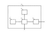
図1に本実施形態におけるネットワークシステム0の構成図を表す。ネットワーク30と各ノード10の送受信装置20を介して、ノード間でデータを送受信する。本実施形態におけるネットワークシステム0は、パケット順序保障がある。また、本実施形態におけるネットワーク30は、データリンク層レベルで送信確認と、再送制御を行うネットワークである。Example 1
FIG. 1 shows a configuration diagram of a
送受信装置20は、パケット送信回路200、ネットワークインタフェース回路400及びパケット受信回路300を有する。パケット送信回路200は、パケットをネットワーク30を介して、別のノード10の送受信装置20に送信する。パケット受信回路300は、別のノード10の送受信装置20からネットワーク30を介してパケットを受信する。ネットワークインタフェース回路400はノード10との間でパケットの送受信を行う。 The transmission /
本実施形態では、パケットの転送速度を向上させるために、カットスルー転送が用いられる。カットスルー転送では、パケットをさらに分割したフリットという単位で転送を行う。送受信装置20は、フリットを順次受信する。送受信装置20は、パケットのヘッダを全て取得すると、当該ヘッダを参照し、パケットの転送先に関する情報を取得する。そして、送受信装置20はパケットの転送先へのパケット転送を開始する。 In this embodiment, cut-through transfer is used to improve the packet transfer rate. In cut-through transfer, transfer is performed in units of flits obtained by further dividing a packet. The transmission /
図2にノード10の構成の一例を表す。ノード10は、システム制御部12、Central Processing Unit(CPU、中央処理装置)14、メモリ16及びInput/Output(I/O、入出力)インタフェース18を有する。CPU14は、データ処理を行う。メモリ16は、データを格納する。システム制御部12は、送受信装置20と接続され、パケットの送受信を行う。I/Oインタフェース18は、他の装置との接続に用いられる。 FIG. 2 shows an example of the configuration of the
図3は、本実施形態において送受信するパケット500のパケットフォーマットを表す。パケット通信方式では、まず送受信するデータをパケットと呼ぶ小さなデータに分割する。次にパケットを送信元のノードから送信先のノードに転送する。 FIG. 3 shows a packet format of a
パケット500は、ヘッダ誤り検出符号502、ヘッダ504、データ506及びパケット誤り検出符号508を有する。ヘッダ誤り検出符号502は、本実施形態の手法で生成するシーケンス番号を畳み込んだ誤り検出符号である。ヘッダ誤り検出符号502はヘッダの誤りを検出するために用いられる。ヘッダ504は、パケットの送信元アドレス、パケットの送信先アドレス、パケットタイプ及びパケット長等の情報を有している。データ506には、任意の情報が含まれる。パケット誤り検出符号508は、データ506の誤りを検出するために用いられる。パケット500の各フィールド長は、例えば次の通りである。ヘッダ誤り検出符号502が2Byte、ヘッダ504が5Byte、データ506が8Byte単位の可変長及びパケット誤り検出符号508が4Byteである。 The
また、本実施形態におけるパケット500の先頭8Byteには、パケットの先頭であることを表すSTPコードが、パケットの末尾8Byteには、パケットの末尾であることを表すENDコードが付加されている。ENDコードには、正常なパケットであることを表すEND、または、エラーを含んだパケットであることを表すEDBのいずれかの情報が書き込まれている。受信回路302は、ENDコードを参照することで、パケットの末尾を検出し、さらにパケットが正常なパケットであるか否かを判定することができる。 In the present embodiment, an STP code indicating the beginning of the packet is added to the first 8 bytes of the
図4は、本実施形態におけるパケット送信回路200の構成を表す。パケット送信回路200は、送信回路202、ヘッダ誤り検出符号生成回路204、パケット誤り検出符号生成回路203及び送信シーケンス番号制御回路207を有する。 FIG. 4 shows a configuration of the
パケット送信回路200には、図1において説明したネットワークインタフェース回路400を経由し、ヘッダとデータが入力する。送信シーケンス番号制御回路207は、次に送信するパケットのシーケンス番号を管理する第一送信カウンタ205と受信側で正常受信できたパケットのシーケンス番号を管理する第二送信カウンタ206を有しており、送信するパケットのシーケンス番号を管理している。第一送信カウンタ205は、パケット送信回路200がパケットを送信するとインクリメントされる。第二送信カウンタ206はパケット受信回路300が正常に受信できたパケットのシーケンス番号にインクリメントされる。 The
ヘッダ誤り検出符号生成回路204は、ネットワークインタフェース回路400からパケット送信回路200に入力するヘッダと、第一送信カウンタ205が示しているシーケンス番号とからヘッダ誤り検出符号を生成する。パケット誤り検出符号生成回路203は、ネットワークインタフェース回路400からパケット送信回路200に入力するデータからパケット誤り検出符号を生成する。なお、ヘッダ誤り検出符号生成回路204及びパケット誤り検出符号生成回路203は、誤り検出符号の生成アルゴリズムとして、例えばCRC(Cyclic Redundancy Check)アルゴリズム等の任意のアルゴリズムを使用すれば良い。送信回路202は、パケットフォーマットに従って、ヘッダ誤り検出符号生成回路204が生成したヘッダ誤り検出符号、ヘッダ、データ及びパケット誤り検出符号生成回路203が生成したパケット誤り検出符号をネットワーク30を経由して宛先のノードに送信する。 The header error detection
以下、図5を用いてパケット送信の処理について説明する。ステップS101において、送信回路202は、ヘッダとデータを受信する。処理はステップS102へ移行する。 Hereinafter, the packet transmission process will be described with reference to FIG. In step S101, the
ステップS102において、ヘッダ誤り検出符号生成回路204は、第一送信カウンタ205が示すシーケンス番号と、送信回路202が受信したヘッダとからヘッダ誤り検出符号を生成する。処理はステップS103へ移行する。 In step S <b> 102, the header error detection
ステップS103において、パケット誤り検出符号生成回路203は、送信回路202が受信したデータからパケット誤り検出符号を生成する。処理はステップS104へ移行する。 In step S103, the packet error detection
ステップS104において、送信回路202は、パケットフォーマットに従い、ヘッダ誤り検出符号、ヘッダ、データ及びパケット誤り検出符号をネットワーク30に送信する。処理は終了する。 In step S104, the
図6は、本実施形態におけるヘッダ誤り検出符号の生成方法を表した概念図である。図6に表すように本実施形態におけるヘッダ誤り検出符号は、シーケンス番号とパケットヘッダ情報を用いて演算することによって生成される。 FIG. 6 is a conceptual diagram showing a method for generating a header error detection code in the present embodiment. As shown in FIG. 6, the header error detection code in the present embodiment is generated by calculating using the sequence number and the packet header information.
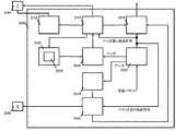
図7は、本実施形態におけるパケット受信回路300の構成を表す。パケット受信回路300は、受信回路302、バッファ304、ヘッダ誤り検出符号生成回路204、パケット誤り検出符号生成回路203、受信シーケンス番号制御回路308、ヘッダ誤り検出符号比較回路310、パケット誤り検出符号比較回路306、及び再送制御回路312を有する。 FIG. 7 shows the configuration of the
パケット受信回路300には、ネットワーク30を経由してパケット送信回路200が送信したパケットが入力する。受信回路302は、パケットを受信する。受信回路302は、受信したパケットをバッファ304に出力する。また、受信回路302は、受信したパケットのヘッダをヘッダ誤り検出符号生成回路204に出力し、受信したパケットの誤り検出符号をヘッダ誤り検出符号比較回路310に出力し、受信したパケットのデータをパケット誤り検出符号比較回路306に出力する。 The packet received by the
バッファ304は、受信回路302から入力するパケットを格納する。受信シーケンス番号制御回路308は、受信カウンタ305を有しており、受信するパケットのシーケンス番号を管理している。初期状態では、受信カウンタ305は第一送信カウンタ205と同じ値を示している。 The
ヘッダ誤り検出符号生成回路204は、受信回路302から入力するヘッダと、受信カウンタ305が示しているシーケンス番号とからヘッダ誤り検出符号を生成する。 The header error detection
パケット誤り検出符号生成回路203は、受信回路302から入力するデータからパケット誤り検出符号を生成する。なお、ヘッダ誤り検出符号生成回路204及びパケット誤り検出符号生成回路203は、誤り検出符号の生成アルゴリズムとして、例えばCRCアルゴリズム等の任意のアルゴリズムを使用すれば良い。 The packet error detection
ヘッダ誤り検出符号生成回路204は、生成したヘッダ誤り検出符号をヘッダ誤り検出符号比較回路310に出力する。ヘッダ誤り検出符号比較回路310は、受信回路302から入力するヘッダ誤り検出符号と、ヘッダ誤り検出符号生成回路204から入力するヘッダ誤り検出符号とを比較する。ヘッダ誤り検出符号比較回路310は、比較の結果、受信回路302から入力するヘッダ誤り検出符号と、ヘッダ誤り検出符号生成回路204から入力するヘッダ誤り検出符号とが一致した場合、一致したことを表す信号をバッファ304、受信シーケンス番号制御回路308に出力する。さらに、ヘッダ誤り検出符号が一致した場合、ヘッダ誤り検出符号比較回路310は、正常なパケットを受信したことを表すACKパケットをパケットの送信元のノード10の送受信装置20の送信シーケンス番号制御回路207に送信する。 The header error detection
受信シーケンス番号制御回路308に、ヘッダ誤り検出符号比較回路310から一致したことを表す信号が入力すると、受信カウンタ305はインクリメントされる。また、送信シーケンス番号制御回路207がACKパケットを受信すると、第二送信カウンタ206はACKパケット中のシーケンス番号にインクリメントされる。パケットが正常に送受信されている場合、パケット送信時に第一送信カウンタ205がインクリメントされ、パケット受信時に受信カウンタ305がインクリメントされる。よって第一送信カウンタ205及び受信カウンタ305は同じ値を示す。 When a signal indicating a match from the header error detection
一方、ヘッダ誤り検出符号比較回路310は、比較の結果、受信回路302から入力するヘッダ誤り検出符号と、ヘッダ誤り検出符号生成回路204から入力するヘッダ誤り検出符号とが一致しない場合、一致しないことを表す信号を再送制御回路312に出力する。再送制御回路312は、当該信号を受信すると、正常なパケットを受信できなかったことを表すNAKパケットを送信元のノード10の送受信装置20の送信シーケンス番号制御回路207に送信する。送信シーケンス番号制御回路207がNAKパケットを受信すると、第二送信カウンタ206はNAKパケット中の正常に受信できたパケットのシーケンス番号にインクリメントされる。送信回路202は第二送信カウンタ206が示すシーケンス番号+1のパケット以降から第一送信カウンタ205が示すシーケンス番号のパケットの再送処理を行う。 On the other hand, the header error detection
パケットの再送を要求する場合としては以下の場合がある。例えば、パケットのヘッダにビット誤りを検出した場合、パケットのヘッダのシーケンス番号がパケット受信回路300で期待するシーケンス番号と一致しない場合、シーケンス番号にビット誤りはないが、前のパケットが欠落していた場合、シーケンス番号にビット誤りがある場合、パケットのデータ本体にビット誤りがあった場合等である。パケット本体のデータにビット誤りがある場合だけでなく、ヘッダにビット誤りがある場合やシーケンス番号が不連続の場合も、再送の対象になる。 There are the following cases for requesting retransmission of a packet. For example, when a bit error is detected in the packet header, if the sequence number in the packet header does not match the sequence number expected by the
パケット誤り検出符号生成回路203は、生成したパケット誤り検出符号をパケット誤り検出符号比較回路306に出力する。パケット誤り検出符号比較回路306は、受信回路302から入力するパケット誤り検出符号と、パケット誤り検出符号生成回路203から入力するパケット誤り検出符号とを比較する。比較の結果、受信回路302から入力するパケット誤り検出符号と、パケット誤り検出符号生成回路203から入力するパケット誤り検出符号とが一致した場合、一致したことを表す信号をバッファ304に出力する。一方、比較の結果、受信回路302から入力するパケット誤り検出符号と、パケット誤り検出符号生成回路203から入力するパケット誤り検出符号とが一致しない場合、一致しないことを表す信号をバッファ304に出力する。バッファ304に一致しないことを表す信号が入力すると、バッファ304に格納されているパケットが破棄される。 The packet error detection
また、パケット誤り検出符号比較回路306は、パケット誤り検出符号生成回路203が生成したパケット誤り検出符号と、受信回路302が受信したパケットのパケット誤り検出符号のビット反転とが一致しない場合、一致しないことを表す信号をパケットの送信先のノード10に接続された送受信装置20のパケット送信回路200に出力する。 The packet error detection
パケットの送信先のノード10に接続された送受信装置20の送信回路202は、当該信号を受信すると、パケットのENDコードにパケットがエラーを含んでいることを表すEDBを書き込む。さらに、送信回路202は、当該信号を受信すると、パケット誤り検出符号生成回路203に正常なパケットのパケット誤り検出符号をビット反転したパケット誤り検出符号を生成させる。そして、送信回路202は、ENDコードがEDBであり、かつ、正常なパケットの誤り検出符号をビット反転したパケット誤り検出符号が付加されたパケットをネットワークに送信する。受信回路302は、ENDコードを参照することで、パケットの末尾の検出及びパケットが正常なパケットであるか否かを判定することができる。また、受信回路302は、受信したパケットのパケット誤り検出符号がビット反転したものであるか否かを判定することにより、パケットを無効にすべきか否かを判定することができる。 When the
カットスルー転送では、転送中にエラーを検出しても、転送をキャンセルすることができないため、転送中のパケットがエラーを含むことをパケットの送信先のノード10に通知する必要がある。そのため、エラーを含むパケットのENDコードをEDBに、誤り検出符号をビット反転したものにしている。 In cut-through transfer, even if an error is detected during transfer, the transfer cannot be canceled. Therefore, it is necessary to notify the
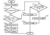
以下、図8を用いてパケット受信の処理について説明する。ステップS201において、ヘッダ誤り検出符号生成回路204、パケット誤り検出符号生成回路203はそれぞれ、ヘッダ誤り検出符号、パケット誤り検出符号を生成する。処理はステップS202へ移行する。 Hereinafter, packet reception processing will be described with reference to FIG. In step S201, the header error detection
ステップS202において、受信回路302は、パケットの末尾がENDであるか否かを判定する。パケットの末尾がENDである場合、処理はステップS203へ移行する。一方、パケットの末尾がENDでない場合、処理はステップS207へ移行する。 In step S202, the
ステップS203において、ヘッダ誤り検出符号比較回路310、パケット誤り検出符号比較回路306はそれぞれ、ステップS201において生成した誤り検出符号と、受信したパケットの誤り検出符号とが一致するか否かを判定する。生成した誤り検出符号と、受信したパケットの誤り検出符号とが一致する場合、処理はステップS204へ移行する。一方、生成した誤り検出符号と、受信したパケットの誤り検出符号とが一致しない場合、処理はステップS209へ移行する。ステップS209において、バッファ304に格納されたパケットは破棄される。 In step S203, the header error detection
ステップS204において、ヘッダ誤り検出符号比較回路310は、シーケンス番号制御回路308に、誤り検出符号が一致したことを表す信号を出力する。受信カウンタ305はインクリメントされる。処理はステップS205へ移行する。 In step S204, the header error detection
ステップS205において、ヘッダ誤り検出符号比較回路310は、正常なパケットを受信したことを表すACKパケットをパケット送信回路200のシーケンス番号制御回路207に送信する。シーケンス番号制御回路207がACKパケットを受信すると、第二送信カウンタ206はインクリメントされる。処理はステップS206へ移行する。 In step S205, the header error detection
ステップS206において、バッファ304は、ヘッダとデータを出力する。処理は終了する。 In step S206, the
続いて、ステップS202からステップS207に移行した場合の処理について説明する。ステップS207において、パケット誤り検出符号比較回路300は、パケット誤り検出符号生成回路203が生成したパケット誤り検出符号と、受信回路302が受信したパケットのパケット誤り検出符号のビット反転とが一致するか否かを判定する。生成したパケット誤り検出符号と、受信したパケット誤り検出符号のビット反転とが一致する場合、受信回路302が受信したパケットは無効パケットであり、処理はステップS208へ移行する。一方、生成したパケット誤り検出符号と、受信したパケット誤り検出符号のビット反転とが一致しない場合、処理はステップS209へ移行する。 Next, processing when the process proceeds from step S202 to step S207 will be described. In step S207, the packet error detection
ステップS208において、バッファ304に格納された無効パケットは破棄される。処理はステップS210へ移行する。 In step S208, the invalid packet stored in the
ステップS210において、ヘッダ誤り検出符号比較回路310は、再送制御回路312にパケットの再送を指示する。再送制御回路312は、ヘッダ誤り検出符号比較回路310からの指示を受け、正常なパケットを受信できなかったことを表すNAKパケットをパケット送信回路200に送信し、パケット再送をパケット送信回路200に要求する。処理は終了する。 In step S210, the header error detection
図9は、本実施形態におけるヘッダ誤りとシーケンス番号の検査方法を表した概念図である。受信回路で保持しているシーケンス番号と、受信したパケットのヘッダから本実施形態におけるヘッダ誤り検出符号を生成する。そして、生成したヘッダ誤り検出符号と、受信したヘッダ誤り検出符号とを比較する。シーケンス番号の不一致、パケットのヘッダにエラーがあると2つの誤り検出符号は一致しない。 FIG. 9 is a conceptual diagram showing a header error and sequence number inspection method in this embodiment. The header error detection code in this embodiment is generated from the sequence number held in the receiving circuit and the header of the received packet. Then, the generated header error detection code is compared with the received header error detection code. If the sequence numbers do not match or there is an error in the packet header, the two error detection codes do not match.
カットスルー転送ではヘッダを全て取得しなければ、転送開始できないため、ヘッダのデータ量によっては、受信するフリットにヘッダが全て含まれていない場合もある。受信するフリットにヘッダが全て含まれていないと、次のフリットの受信を待って、ヘッダを全て取得しなければならず、次のフリットの受信を待つ時間だけ、パケットの転送開始が遅れてしまう。ゆえに、本実施形態によれば、ヘッダにシーケンス番号を含めないため、ヘッダのデータ量を小さくすることができ、受信するフリットにヘッダを含めることができる確率が向上する。 In cut-through transfer, transfer cannot be started unless all the headers are acquired. Therefore, depending on the amount of header data, the headers may not be included in the received flits. If all the headers are not included in the received flit, it is necessary to wait until the next flit is received and acquire all the headers, and the packet transfer start is delayed by the time waiting for the next flit to be received. . Therefore, according to the present embodiment, since the sequence number is not included in the header, the data amount of the header can be reduced, and the probability that the header can be included in the received flit is improved.
(実施例2)
図10は、本実施形態において送受信するパケット500のパケットフォーマットを表す。パケット500は、ヘッダ504、データ506及びパケット誤り検出符号508を有する。ヘッダ504は、パケットの送信元アドレス、パケットの送信先アドレス、パケットタイプ及びパケット長等の情報を有している。(Example 2)
FIG. 10 shows a packet format of the
図11は、本実施形態におけるパケット送信回路200の構成を表す。パケット送信回路200は、送信回路202、パケット誤り検出符号生成回路314及び送信シーケンス番号制御回路207を有する。送信シーケンス番号制御回路207は、次に送信するパケットのシーケンス番号を管理する第一送信カウンタ205と受信側で正常受信できたパケットのシーケンス番号を管理する第二送信カウンタ206を有する。 FIG. 11 shows the configuration of the
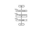
以下、図12を用いてパケット送信の処理について説明する。ステップS301において、送信回路202は、ノード10から送信されるヘッダとデータを受信する。処理はステップS302へ移行する。 Hereinafter, packet transmission processing will be described with reference to FIG. In step S301, the
ステップS302において、パケット誤り検出符号生成回路314は、第一送信カウンタ205が示すシーケンス番号と、送信回路202が受信したヘッダ及びデータとからヘッダ誤り検出符号を生成する。なお、パケット誤り検出符号生成回路314によるパケット誤り検出符号の生成アルゴリズムとしては、CRCアルゴリズム等の任意のアルゴリズムが使用されれば良い。処理はステップS303へ移行する。 In step S302, the packet error detection
ステップS303において、送信回路202は、パケットフォーマットに従い、パケット誤り検出符号、ヘッダ及びデータをネットワーク30に送信する。処理は終了する。 In step S <b> 303, the
図13は、本実施形態におけるパケット受信回路300の構成を表す。パケット受信回路300は、受信回路302、バッファ304、パケット誤り検出符号生成回路314、シーケンス番号制御回路308、パケット誤り検出符号比較回路316及び再送制御回路312を有する。シーケンス番号制御回路308は、受信カウンタ305を有する。 FIG. 13 shows the configuration of the
以下、図14を用いてパケット受信の処理について説明する。ステップS401において、パケット誤り検出符号生成回路314は、パケット誤り検出符号を生成する。処理はステップS402へ移行する。 Hereinafter, packet reception processing will be described with reference to FIG. In step S401, the packet error detection
ステップS402において、受信回路302は、パケットの末尾がENDであるか否かを判定する。パケットの末尾がENDである場合、処理はステップS403へ移行する。一方、パケットの末尾がENDでない場合、処理はステップS407へ移行する。 In step S402, the
ステップS403において、パケット誤り検出符号比較回路316は、ステップS401において生成したパケット誤り検出符号と、受信したパケットの誤り検出符号とが一致するか否かを判定する。生成したパケット誤り検出符号と、受信したパケットのパケット誤り検出符号とが一致する場合、処理はステップS404へ移行する。一方、生成したパケット誤り検出符号と、受信したパケットのパケット誤り検出符号とが一致しない場合、処理はステップS409へ移行する。ステップS409において、バッファ304に格納されたパケットは破棄される。 In step S403, the packet error detection
ステップS404において、パケット誤り検出符号比較回路316は、シーケンス番号制御回路308に、誤り検出符号が一致したことを表す信号を出力する。受信カウンタ305はインクリメントされる。処理はステップS405へ移行する。 In step S404, the packet error detection
ステップS405において、パケット誤り検出符号比較回路316は、正常なパケットを受信したことを表すACKパケットをパケット送信回路200のシーケンス番号制御回路207に送信する。シーケンス番号制御回路207がACKパケットを受信すると、第二送信カウンタ206はインクリメントされる。処理はステップS406へ移行する。 In step S405, the packet error detection
ステップS406において、バッファ304は、ヘッダとデータを出力する。処理は終了する。 In step S406, the
続いて、ステップS402からステップS407に移行した場合の処理について説明する。ステップS407において、パケット誤り検出符号比較回路300は、パケット誤り検出符号生成回路314が生成したパケット誤り検出符号と、受信回路302が受信したパケットのパケット誤り検出符号のビット反転とが一致するか否かを判定する。生成したパケット誤り検出符号と、受信したパケット誤り検出符号のビット反転とが一致する場合、受信回路302が受信したパケットは無効パケットであり、処理はステップS408へ移行する。一方、生成したパケット誤り検出符号と、受信したパケット誤り検出符号のビット反転とが一致しない場合、処理はステップS409へ移行する。 Next, processing when the process proceeds from step S402 to step S407 will be described. In step S407, the packet error detection
ステップS408において、バッファ304に格納された無効パケットは破棄される。処理はステップS410へ移行する。 In step S408, the invalid packet stored in the
ステップS410において、パケット誤り検出符号比較回路316は、再送制御回路312にパケットの再送を指示する。再送制御回路312は、パケット誤り検出符号比較回路316からの指示を受け、正常なパケットを受信できなかったことを表すNAKパケットをパケット送信回路200に送信し、パケット再送をパケット送信回路200に要求する。処理は終了する。 In step S410, the packet error detection
(本実施形態の有効性)
図15は、送受信するデータとパケット構造の対応を表す。図15に表すように、パケットは分割したデータのそれぞれにヘッダという情報を付加したデータである。図15に表すパケットでは、ヘッダにはシーケンス番号が含まれている。本実施形態における送受信回路では、送信回路が送信するパケットのシーケンス番号と、受信回路が受信するパケットのシーケンス番号とは一致するように制御されている。そのため、送信回路、受信回路それぞれで管理しているシーケンス番号を用いて誤り検出符号を生成すれば、シーケンス番号をパケットに含めなくても良くなる。ゆえに、送受信回路の通信帯域を有効活用することができる。(Effectiveness of this embodiment)
FIG. 15 shows the correspondence between the data to be transmitted and received and the packet structure. As shown in FIG. 15, a packet is data in which information called a header is added to each of divided data. In the packet shown in FIG. 15, the header includes a sequence number. In the transmission / reception circuit according to the present embodiment, the sequence number of the packet transmitted by the transmission circuit and the sequence number of the packet received by the reception circuit are controlled to match. Therefore, if the error detection code is generated using the sequence number managed by each of the transmission circuit and the reception circuit, the sequence number need not be included in the packet. Therefore, the communication band of the transmission / reception circuit can be effectively used.
以上の説明は、本実施形態をより良く理解させるために具体的に説明したものであって、別形態を制限するものではない。従って、趣旨を変更しない範囲で変更可能である。 The above description is specifically described for better understanding of the present embodiment, and does not limit other embodiments. Therefore, it can be changed without changing the purpose.
0 ネットワークシステム
10 ノード
12 システム制御部
14 CPU
16 メモリ
18 I/Oインタフェース
20 送受信装置
30 ネットワーク
200 送信回路
202 パケット送信回路
204 ヘッダ誤り検出符号生成回路
205 第一送信カウンタ
206 第二送信カウンタ
207 送信シーケンス番号制御回路
208 パケット誤り検出符号生成回路
300 受信回路
302 パケット受信回路
304 バッファ
306 ヘッダ誤り検出符号生成回路
308 受信シーケンス番号制御回路
310 ヘッダ誤り検出符号比較回路
312 再送制御回路
314 パケット誤り検出符号生成回路
316 パケット誤り検出符号比較回路
400 ネットワークインタフェース回路
500 パケット
502 ヘッダ誤り検出符号
504 ヘッダ
506 データ
508 パケット誤り検出符号0
16 memory 18 I /
Claims (10)
Translated fromJapanese該パケットの送信順序を示す順序情報を管理する第一の管理部と、該パケット内の情報の一部と該第一の管理部が管理する該順序情報に基づき該パケット内の情報の少なくとも一部に対する誤りを検出する誤り検出情報を生成する第一の誤り検出情報生成部と、該誤り検出情報を該パケットに付加して送信する送信部とを有する送信回路と、
該送信部から送信される該パケットの受信順序を示す順序情報を管理する第二の管理部と、該送信部から送信される該パケット内の情報の少なくとも一部と該第二の管理部が管理する該順序情報に基づき、該パケット内の情報の少なくとも一部に対する誤りを検出する誤り検出情報を生成する第二の誤り検出情報生成部と、該第二の誤り検出情報生成部が生成した該誤り検出情報と該パケットに付加された該誤り検出情報とを比較することによって該パケットの誤りを検出する誤り検出部とを有する受信回路と、
を有することを特徴とする送受信回路。In a transmission / reception circuit for transmitting / receiving packets,
A first management unit that manages order information indicating a transmission order of the packet; and at least one piece of information in the packet based on part of the information in the packet and the order information managed by the first management unit. A transmission circuit having a first error detection information generation unit that generates error detection information for detecting an error with respect to a unit, and a transmission unit that adds the error detection information to the packet and transmits the packet,
A second management unit for managing order information indicating the reception order of the packets transmitted from the transmission unit, at least a part of the information in the packet transmitted from the transmission unit, and the second management unit. Based on the order information to be managed, a second error detection information generation unit that generates error detection information for detecting an error for at least a part of the information in the packet, and the second error detection information generation unit A receiving circuit having an error detection unit that detects an error of the packet by comparing the error detection information and the error detection information added to the packet;
A transmission / reception circuit comprising:
該パケットの送信順序を示す順序情報を管理する管理部と、
該パケット内の情報の少なくとも一部と該順序情報とに基づき、該パケットの誤りを検出する誤り検出情報を生成する誤り検出情報生成部と、
該誤り検出情報を該パケットに付加して送信する送信部と、
を有することを特徴とする送信回路。In a transmission circuit connected to a reception circuit that receives a packet,
A management unit that manages order information indicating the transmission order of the packets;
An error detection information generating unit that generates error detection information for detecting an error of the packet based on at least a part of the information in the packet and the order information;
A transmission unit that adds the error detection information to the packet and transmits the packet;
A transmission circuit comprising:
該パケット内の情報の少なくとも一部と送信する該パケットの送信順序を示す順序情報とに基づき、該パケットの誤りを検出する第一の誤り検出情報を生成し、
該誤り検出情報を該パケットに付加して送信し、
受信した該パケット内の情報の少なくとも一部と受信する該パケットの受信順序を示す順序情報とに基づき、該データの誤りを検出する第二の誤り検出情報を生成し、
該第一の誤り検出情報と該パケットに付加された該第二の誤り検出情報とを比較することによって該パケットの誤りを検出すること、
を特徴とする送受信方法。In a transmission / reception method for transmitting / receiving packets,
Generating first error detection information for detecting an error in the packet based on at least part of the information in the packet and order information indicating a transmission order of the packet to be transmitted;
Add the error detection information to the packet and send it,
Generating second error detection information for detecting an error in the data based on at least a part of the information in the received packet and order information indicating the reception order of the received packet;
Detecting an error in the packet by comparing the first error detection information with the second error detection information added to the packet;
A transmission / reception method characterized by the above.
Priority Applications (5)
| Application Number | Priority Date | Filing Date | Title |
|---|---|---|---|
| JP2008170487AJP4985565B2 (en) | 2008-06-30 | 2008-06-30 | Transmission / reception circuit, reception circuit, and control method for transmission / reception circuit |
| US12/485,529US8255560B2 (en) | 2008-06-30 | 2009-06-16 | System for transmitting and receiving packets |
| EP20090163526EP2141849A3 (en) | 2008-06-30 | 2009-06-23 | System for transmitting and receiving packets with an error check code |
| CN2009101463993ACN101621471B (en) | 2008-06-30 | 2009-06-26 | System for transmitting and receiving packets |
| KR20090058261AKR20100003227A (en) | 2008-06-30 | 2009-06-29 | Transmitting/receiving circuit, transmitting circuit, and transmitting/receiving method |
Applications Claiming Priority (1)
| Application Number | Priority Date | Filing Date | Title |
|---|---|---|---|
| JP2008170487AJP4985565B2 (en) | 2008-06-30 | 2008-06-30 | Transmission / reception circuit, reception circuit, and control method for transmission / reception circuit |
Publications (2)
| Publication Number | Publication Date |
|---|---|
| JP2010011296Atrue JP2010011296A (en) | 2010-01-14 |
| JP4985565B2 JP4985565B2 (en) | 2012-07-25 |
Family
ID=41060009
Family Applications (1)
| Application Number | Title | Priority Date | Filing Date |
|---|---|---|---|
| JP2008170487AExpired - Fee RelatedJP4985565B2 (en) | 2008-06-30 | 2008-06-30 | Transmission / reception circuit, reception circuit, and control method for transmission / reception circuit |
Country Status (5)
| Country | Link |
|---|---|
| US (1) | US8255560B2 (en) |
| EP (1) | EP2141849A3 (en) |
| JP (1) | JP4985565B2 (en) |
| KR (1) | KR20100003227A (en) |
| CN (1) | CN101621471B (en) |
Cited By (8)
| Publication number | Priority date | Publication date | Assignee | Title |
|---|---|---|---|---|
| JP2013078004A (en)* | 2011-09-30 | 2013-04-25 | Nec Corp | Communication system, data transmission device, data reception device, packet retransmission control method and packet retransmission control program |
| JP2014207010A (en)* | 2014-07-15 | 2014-10-30 | 日立オートモティブシステムズ株式会社 | Electronic control device for automobile |
| JP2015506145A (en)* | 2011-12-08 | 2015-02-26 | クゥアルコム・テクノロジーズ・インコーポレイテッド | Differential formatting between normal data transmission and retry data transmission |
| JP2015508978A (en)* | 2012-03-02 | 2015-03-23 | エルエス産電株式会社Lsis Co., Ltd. | Communication apparatus and communication method |
| JP2015508976A (en)* | 2012-03-02 | 2015-03-23 | エルエス産電株式会社Lsis Co., Ltd. | Communication apparatus and communication method |
| JP2015508977A (en)* | 2012-03-02 | 2015-03-23 | エルエス産電株式会社Lsis Co., Ltd. | Communication apparatus and communication method |
| JP2016507971A (en)* | 2013-01-07 | 2016-03-10 | クアルコム,インコーポレイテッド | Additional error protection for wireless transmission |
| US10353594B2 (en) | 2011-09-21 | 2019-07-16 | Hitachi Automotive Systems, Ltd. | Electronic control unit for vehicle and method of writing data |
Families Citing this family (13)
| Publication number | Priority date | Publication date | Assignee | Title |
|---|---|---|---|---|
| US8683095B1 (en) | 2010-06-02 | 2014-03-25 | Marvell International Ltd | Packet identification tracker |
| US9391671B2 (en)* | 2011-05-06 | 2016-07-12 | Samsung Electronics Co., Ltd. | Wireless power transmission and charging system and method thereof |
| US8838999B1 (en) | 2011-05-17 | 2014-09-16 | Applied Micro Circuits Corporation | Cut-through packet stream encryption/decryption |
| CN102255713B (en)* | 2011-07-24 | 2013-10-30 | 哈尔滨工程大学 | Data packets of underwater sound sensor network and transmission method |
| CN103188059A (en)* | 2011-12-28 | 2013-07-03 | 华为技术有限公司 | Method, device and system for data packet retransmission in quick path interconnect system |
| US9201722B1 (en)* | 2014-07-10 | 2015-12-01 | Freescale Semiconductor, Inc. | System-on-chip and method for sending data in a system-on-chip |
| US9749448B2 (en)* | 2014-11-25 | 2017-08-29 | Intel Corporation | Header parity error handling |
| JP2017063273A (en)* | 2015-09-24 | 2017-03-30 | 富士通株式会社 | Transmission apparatus and transmission system |
| EP3166246B1 (en)* | 2015-11-06 | 2018-06-20 | Fts Computertechnik Gmbh | Method to detect and to handle failures in the communication in a computer network |
| US10791062B1 (en)* | 2017-11-14 | 2020-09-29 | Amazon Technologies, Inc. | Independent buffer memory for network element |
| EP3565186B1 (en)* | 2018-05-02 | 2021-06-30 | TTTech Computertechnik AG | Device and network to reliably communicate in a network |
| WO2022014089A1 (en)* | 2020-07-16 | 2022-01-20 | 富士フイルム株式会社 | Ultrasonic system and method for controlling ultrasonic system |
| CN114884622A (en)* | 2022-05-23 | 2022-08-09 | 海光信息技术股份有限公司 | Data transmission method and related device |
Citations (5)
| Publication number | Priority date | Publication date | Assignee | Title |
|---|---|---|---|---|
| JPH05336149A (en)* | 1992-05-28 | 1993-12-17 | Nec Corp | Bit error/missing cell detection system in atm communication |
| JPH09162873A (en)* | 1995-12-05 | 1997-06-20 | Nippon Telegr & Teleph Corp <Ntt> | Error detection method and device |
| JP2002026963A (en)* | 2000-03-03 | 2002-01-25 | Ntt Docomo Inc | Packet transmission method, relay device and data terminal |
| JP2002094553A (en)* | 2000-09-12 | 2002-03-29 | Matsushita Electric Ind Co Ltd | Packet transmission device and packet transmission method |
| JP2002135362A (en)* | 2000-08-17 | 2002-05-10 | Matsushita Electric Ind Co Ltd | Header compression apparatus and header compression method |
Family Cites Families (11)
| Publication number | Priority date | Publication date | Assignee | Title |
|---|---|---|---|---|
| US5953418A (en)* | 1995-06-14 | 1999-09-14 | David Hall | Providing selective data broadcast receiver addressability |
| US6088337A (en)* | 1997-10-20 | 2000-07-11 | Motorola, Inc. | Method access point device and peripheral for providing space diversity in a time division duplex wireless system |
| US6754231B1 (en)* | 1999-06-18 | 2004-06-22 | Telefonaktiebolaget Lm Ericsson (Publ) | Robust header compression in packet communications |
| US7126950B2 (en)* | 2000-02-14 | 2006-10-24 | Nec Corporation | Method and system for transmission and reception of asynchronously multiplexed signals |
| JP3323484B2 (en)* | 2000-09-12 | 2002-09-09 | 松下電器産業株式会社 | Packet transmitting device, packet receiving device, and packet transmission method |
| US6684363B1 (en)* | 2000-10-25 | 2004-01-27 | Sun Microsystems, Inc. | Method for detecting errors on parallel links |
| US6931581B1 (en)* | 2000-10-25 | 2005-08-16 | Sun Microsystems, Inc. | Method for superimposing a sequence number in an error detection code in a data network |
| JP3600189B2 (en)* | 2001-06-19 | 2004-12-08 | 松下電器産業株式会社 | Packet transmitting / receiving apparatus and packet transmitting method |
| US20030066016A1 (en) | 2001-09-28 | 2003-04-03 | Eric Wehage | Methodology for detecting lost packets |
| JP4284280B2 (en)* | 2005-01-18 | 2009-06-24 | 株式会社東芝 | Wireless communication system and wireless transmission device |
| US20080195912A1 (en)* | 2007-02-14 | 2008-08-14 | Nokia Corporation | Method of communicatoin |
- 2008
- 2008-06-30JPJP2008170487Apatent/JP4985565B2/ennot_activeExpired - Fee Related
- 2009
- 2009-06-16USUS12/485,529patent/US8255560B2/ennot_activeExpired - Fee Related
- 2009-06-23EPEP20090163526patent/EP2141849A3/ennot_activeWithdrawn
- 2009-06-26CNCN2009101463993Apatent/CN101621471B/ennot_activeExpired - Fee Related
- 2009-06-29KRKR20090058261Apatent/KR20100003227A/ennot_activeCeased
Patent Citations (5)
| Publication number | Priority date | Publication date | Assignee | Title |
|---|---|---|---|---|
| JPH05336149A (en)* | 1992-05-28 | 1993-12-17 | Nec Corp | Bit error/missing cell detection system in atm communication |
| JPH09162873A (en)* | 1995-12-05 | 1997-06-20 | Nippon Telegr & Teleph Corp <Ntt> | Error detection method and device |
| JP2002026963A (en)* | 2000-03-03 | 2002-01-25 | Ntt Docomo Inc | Packet transmission method, relay device and data terminal |
| JP2002135362A (en)* | 2000-08-17 | 2002-05-10 | Matsushita Electric Ind Co Ltd | Header compression apparatus and header compression method |
| JP2002094553A (en)* | 2000-09-12 | 2002-03-29 | Matsushita Electric Ind Co Ltd | Packet transmission device and packet transmission method |
Cited By (13)
| Publication number | Priority date | Publication date | Assignee | Title |
|---|---|---|---|---|
| US11360698B2 (en) | 2011-09-21 | 2022-06-14 | Hitachi Astemo, Ltd. | Electronic control unit for vehicle and method of writing data |
| US10353594B2 (en) | 2011-09-21 | 2019-07-16 | Hitachi Automotive Systems, Ltd. | Electronic control unit for vehicle and method of writing data |
| JP2013078004A (en)* | 2011-09-30 | 2013-04-25 | Nec Corp | Communication system, data transmission device, data reception device, packet retransmission control method and packet retransmission control program |
| JP2015506145A (en)* | 2011-12-08 | 2015-02-26 | クゥアルコム・テクノロジーズ・インコーポレイテッド | Differential formatting between normal data transmission and retry data transmission |
| US10142058B2 (en) | 2012-03-02 | 2018-11-27 | Lsis Co., Ltd. | Communication device and communication method |
| JP2015508977A (en)* | 2012-03-02 | 2015-03-23 | エルエス産電株式会社Lsis Co., Ltd. | Communication apparatus and communication method |
| US10044469B2 (en) | 2012-03-02 | 2018-08-07 | Lsis Co., Ltd. | Communication device and communication method |
| JP2015508976A (en)* | 2012-03-02 | 2015-03-23 | エルエス産電株式会社Lsis Co., Ltd. | Communication apparatus and communication method |
| US10237018B2 (en) | 2012-03-02 | 2019-03-19 | Lsis Co., Ltd. | Communication device and communication method |
| JP2015508978A (en)* | 2012-03-02 | 2015-03-23 | エルエス産電株式会社Lsis Co., Ltd. | Communication apparatus and communication method |
| JP2016507971A (en)* | 2013-01-07 | 2016-03-10 | クアルコム,インコーポレイテッド | Additional error protection for wireless transmission |
| US9459953B2 (en) | 2013-01-07 | 2016-10-04 | Qualcomm Incorporated | Additional error protection for wireless transmission |
| JP2014207010A (en)* | 2014-07-15 | 2014-10-30 | 日立オートモティブシステムズ株式会社 | Electronic control device for automobile |
Also Published As
| Publication number | Publication date |
|---|---|
| EP2141849A3 (en) | 2013-12-18 |
| US20090327826A1 (en) | 2009-12-31 |
| CN101621471B (en) | 2013-05-08 |
| KR20100003227A (en) | 2010-01-07 |
| EP2141849A2 (en) | 2010-01-06 |
| CN101621471A (en) | 2010-01-06 |
| JP4985565B2 (en) | 2012-07-25 |
| US8255560B2 (en) | 2012-08-28 |
Similar Documents
| Publication | Publication Date | Title |
|---|---|---|
| JP4985565B2 (en) | Transmission / reception circuit, reception circuit, and control method for transmission / reception circuit | |
| US20080195912A1 (en) | Method of communicatoin | |
| EP2978171B1 (en) | Communication method, communication device, and communication program | |
| JP2007174644A (en) | Synchronized data communication | |
| WO2011046056A1 (en) | Transmission control method for packet communication and packet communication system | |
| CN103141050B (en) | Data packet retransmission method and nodes in fast channel interconnection system | |
| US9197373B2 (en) | Method, apparatus, and system for retransmitting data packet in quick path interconnect system | |
| JP2013513269A (en) | Reliable packet cut-through | |
| CN115777184B (en) | Data retransmission method and device | |
| CN106254041A (en) | Data transmission method, data receiver method and device thereof | |
| CN103368703B (en) | Data package retransmission method, data packet receiving method and device | |
| CN109981385A (en) | A kind of methods, devices and systems for realizing packet loss detection | |
| CN110299973B (en) | Receiving method and device for data rolling transmission | |
| CN109039552A (en) | A kind of data reconstruction method and device | |
| US20170288814A1 (en) | A transmitter that does not resend a packet despite receipt of a message to resend the packet | |
| CN110299971B (en) | Data message receiving method and device | |
| WO2018137218A1 (en) | Data transmission method, data receiving device, and data sending device | |
| US20150117176A1 (en) | Data communications using connectionless-oriented protocol | |
| CN114095117A (en) | Retransmission method and related device for Ethernet error frame | |
| CN104125169B (en) | Chain table processing device, chain table processing method and related network switch | |
| CN110299969B (en) | Method and device for transmitting data in rolling mode | |
| JP4807828B2 (en) | Envelope packet architecture for broadband engines | |
| US10938516B1 (en) | Systems and methods for ethernet packet error detection and correction in automotive environments | |
| JP2017103734A (en) | Communication device, control method therefor and program | |
| JP2002261737A (en) | Transmission data loss detection system |
Legal Events
| Date | Code | Title | Description |
|---|---|---|---|
| A621 | Written request for application examination | Free format text:JAPANESE INTERMEDIATE CODE: A621 Effective date:20110315 | |
| A977 | Report on retrieval | Free format text:JAPANESE INTERMEDIATE CODE: A971007 Effective date:20111125 | |
| A131 | Notification of reasons for refusal | Free format text:JAPANESE INTERMEDIATE CODE: A131 Effective date:20111206 | |
| A521 | Request for written amendment filed | Free format text:JAPANESE INTERMEDIATE CODE: A523 Effective date:20120203 | |
| TRDD | Decision of grant or rejection written | ||
| A01 | Written decision to grant a patent or to grant a registration (utility model) | Free format text:JAPANESE INTERMEDIATE CODE: A01 Effective date:20120403 | |
| A01 | Written decision to grant a patent or to grant a registration (utility model) | Free format text:JAPANESE INTERMEDIATE CODE: A01 | |
| A61 | First payment of annual fees (during grant procedure) | Free format text:JAPANESE INTERMEDIATE CODE: A61 Effective date:20120416 | |
| R150 | Certificate of patent or registration of utility model | Free format text:JAPANESE INTERMEDIATE CODE: R150 Ref document number:4985565 Country of ref document:JP Free format text:JAPANESE INTERMEDIATE CODE: R150 | |
| FPAY | Renewal fee payment (event date is renewal date of database) | Free format text:PAYMENT UNTIL: 20150511 Year of fee payment:3 | |
| LAPS | Cancellation because of no payment of annual fees |