JP2010006089A - Aerial photographing device of disaster-stricken, damaged and deteriorated state of facility such as for lifeline - Google Patents
Aerial photographing device of disaster-stricken, damaged and deteriorated state of facility such as for lifelineDownload PDFInfo
- Publication number
- JP2010006089A JP2010006089AJP2008163937AJP2008163937AJP2010006089AJP 2010006089 AJP2010006089 AJP 2010006089AJP 2008163937 AJP2008163937 AJP 2008163937AJP 2008163937 AJP2008163937 AJP 2008163937AJP 2010006089 AJP2010006089 AJP 2010006089A
- Authority
- JP
- Japan
- Prior art keywords
- axis
- helicopter
- imaging device
- radio
- skid
- Prior art date
- Legal status (The legal status is an assumption and is not a legal conclusion. Google has not performed a legal analysis and makes no representation as to the accuracy of the status listed.)
- Pending
Links
- 238000003384imaging methodMethods0.000claimsabstractdescription65
- 238000004891communicationMethods0.000claimsabstractdescription21
- 230000006866deteriorationEffects0.000claimsabstractdescription9
- 230000005540biological transmissionEffects0.000description8
- 238000010586diagramMethods0.000description8
- RZVHIXYEVGDQDX-UHFFFAOYSA-N9,10-anthraquinoneChemical compoundC1=CC=C2C(=O)C3=CC=CC=C3C(=O)C2=C1RZVHIXYEVGDQDX-UHFFFAOYSA-N0.000description4
- 238000000034methodMethods0.000description4
- 238000013480data collectionMethods0.000description3
- 230000006870functionEffects0.000description3
- 239000012212insulatorSubstances0.000description3
- 238000001514detection methodMethods0.000description2
- 239000000725suspensionSubstances0.000description2
- 238000004804windingMethods0.000description2
- 101000934888Homo sapiens Succinate dehydrogenase cytochrome b560 subunit, mitochondrialProteins0.000description1
- 102100025393Succinate dehydrogenase cytochrome b560 subunit, mitochondrialHuman genes0.000description1
- 238000013459approachMethods0.000description1
- 238000012790confirmationMethods0.000description1
- 229940124568digestive agentDrugs0.000description1
- 230000007613environmental effectEffects0.000description1
- 238000005259measurementMethods0.000description1
- NJPPVKZQTLUDBO-UHFFFAOYSA-NnovaluronChemical compoundC1=C(Cl)C(OC(F)(F)C(OC(F)(F)F)F)=CC=C1NC(=O)NC(=O)C1=C(F)C=CC=C1FNJPPVKZQTLUDBO-UHFFFAOYSA-N0.000description1
- 238000012545processingMethods0.000description1
- 230000004044responseEffects0.000description1
Images


Landscapes
- Studio Devices (AREA)
Abstract
Translated fromJapaneseDescription
Translated fromJapanese本発明は、遠隔制御(remote control)或いは自律制御(automatic control)によって飛行する無線操縦ヘリコプタ(radio controlled helicopter、以下、ラジコンヘリと略称する。)によって、台風、地震等の天災に起因する、ライフラインたとえば送電系統等の送電線、電柱、碍子等施設の被災、損傷状況或いは経年変化による送電線、碍子等の劣化状況を、無人のラジコンヘリによって撮像し、これを無線LANにより地上基地局へ画像を伝送するライフライン等の施設の被災、損傷、劣化状況の空撮装置に関する。 The present invention relates to life caused by natural disasters such as typhoons and earthquakes by a radio controlled helicopter (hereinafter abbreviated as a radio control helicopter) that flies by remote control or automatic control. Lines such as power transmission lines such as power transmission systems, utility poles, insulators, etc. Damage, damage or deterioration of power transmission lines, insulators, etc. due to secular changes are imaged with an unmanned radio control helicopter, and this is transmitted to the ground base station via wireless LAN The present invention relates to an aerial imaging device for damage, damage, and deterioration of facilities such as lifelines that transmit images.
地震、台風、津波などの災害発生時、送電系統等ライフラインを確保するために、送電線、電柱、碍子等施設の被災、損傷状況の迅速な把握が必要となる。従来、たとえば送電系統にあって、山間地や離島など直接に近づくことが困難な被災現場における倒壊電柱等の損傷状況を、有人ヘリコプタによって確認している。有人ヘリコプタによる被災状況等の確認には飛行高度、天候(風速など)による制約があり、必ずしも状況を的確に捉えることができない問題がある。そこで、これら制約を可及的に排除できる、ライフライン等施設の被災状況の画像情報収集手段が望まれている。 In the event of a disaster such as an earthquake, typhoon, or tsunami, it is necessary to quickly grasp the damage and damage status of facilities such as transmission lines, utility poles, and insulators in order to secure lifelines such as transmission systems. Conventionally, for example, in a power transmission system, a damaged state such as a collapsed power pole in a disaster site that is difficult to approach directly such as a mountainous area or a remote island is confirmed by a manned helicopter. There is a problem that the situation cannot be accurately grasped because there are restrictions on the flight altitude and weather (wind speed, etc.) in the confirmation of the damage situation by the manned helicopter. Therefore, there is a demand for a means for collecting image information about the damage status of facilities such as lifelines, which can eliminate these restrictions as much as possible.
このような要請に応えるものとして、無人飛行体に、カメラと、カメラから出力される映像データを記録する手段を装備した空撮装置であって、飛行中に機体と撮影対象間の距離を測定し、その結果からカメラのズーム倍率を決定して対象を撮影しまた、カメラを上下又は左右に変化させながら対象の映像データを取り込むようにした空撮方法及び装置が提案されている(たとえば、特許文献1参照)。
上記特許文献1に開示の無人飛行体を利用した空撮装置は、予め設定された所定のルートで無人飛行体を飛行せしめる自律飛行装置と、GPS信号から飛行中の位置を特定する飛行位置特定手段と、機体と撮影対象間の距離を測定する測距手段と、カメラのアングル、ズーム倍率、撮影開始及び終了などを制御するカメラ制御手段と、撮影の開始位置、カメラのアングル、撮影開始位置から対象までの距離、カメラのズーム倍率、撮影終了位置などの撮影条件情報の記録手段、撮影開始位置で測距手段を制御して機体と対象間の距離を測定する実距離測定手段と、測定された対象までの実距離と撮影条件情報に記録されている対象までの距離との差からカメラフレーム内で被写体が所定の大きさとなるようにカメラのズーム倍率を算出し、算出されたズーム倍率に前記撮影条件を更新する手段と、前記撮影条件情報に基づき前記各手段を制御する撮影処理制御手段とを機体に備えた構成となっている。 The aerial imaging device using the unmanned air vehicle disclosed in
しかしながら、上記特許文献1に開示の無人飛行体を利用した空撮装置は、特許文献1における図1に示されているように、カメラはヘリコプタの前端部に配置されており、たとえば台風の直後等の悪天候下、機体の向きやロータブレードの回転面の傾き等、ラジコンヘリのホバリング姿勢が風向き等によって厳しく制限される状況にあって、たとえば飛行体の後ろ向きの方向に対象がある場合に、対象を所望の角度、距離から的確に撮像することができない問題がある。 However, in the aerial imaging apparatus using the unmanned aerial vehicle disclosed in
本発明は、上記のような状況においても対象を的確に撮像することができる、ラジコンヘリによる空撮装置を提供することを目的とする。 An object of the present invention is to provide an aerial imaging device using a radio control helicopter that can accurately capture an image of a subject even in the above situation.
上記課題を解決するための本発明は、ラジコンヘリコプタに、少なくとも該ヘリコプタを遠隔操縦するための制御装置(PC)、撮像装置、GPS用アンテナ、無線通信装置、バッテリ、およびジャイロスコープを搭載したライフライン等の施設の被災、損傷、劣化状況の空撮装置であって、前記ラジコンヘリコプタの飛行方向(X軸)に垂直かつ鉛直方向(Z軸)の軸心回りに360°回転自在なスキッドと、該スキッドに搭載され、X軸に垂直かつ水平方向(Y軸)の軸心回りに回転自在な前記撮像装置の配設用台座を設けてなるライフライン等の施設の被災、損傷、劣化状況の空撮装置である。 The present invention for solving the above-described problems is a life in which a radio control helicopter is equipped with at least a control device (PC) for remotely maneuvering the helicopter, an imaging device, a GPS antenna, a wireless communication device, a battery, and a gyroscope. An aerial imaging device for damage, damage, and deterioration of facilities such as a line, and a skid that can rotate 360 ° about the axis of the radio controlled helicopter in the vertical direction (X axis) and in the vertical direction (Z axis) Damage, damage, or deterioration of facilities such as lifelines that are mounted on the skid and that are provided with a mounting base for the imaging device that is perpendicular to the X axis and rotatable about the axis in the horizontal direction (Y axis) Aerial camera.
本発明によれば、撮像手段はラジコンヘリの進行方向(X軸)に垂直な上下方向(Z軸)回りに360°、X軸に垂直な水平方向(Y軸)回りに360°回転することができるから、たとえば台風の直後等の悪天候下、機体の向きやロータブレードの回転面の傾き等、ラジコンヘリのホバリング姿勢が風向き等によって厳しく制限される状況にあっても、ラジコンヘリの機体の姿勢とは独立に、対象をあらゆる角度から的確に捉えることができる。 According to the present invention, the imaging means rotates 360 ° around the vertical direction (Z axis) perpendicular to the traveling direction (X axis) of the radio control helicopter and 360 ° around the horizontal direction (Y axis) perpendicular to the X axis. Therefore, even if the hovering posture of the radio control helicopter is severely restricted by the wind direction, such as the orientation of the aircraft and the inclination of the rotor blade rotation surface, such as immediately after a typhoon, the radio control helicopter Independent of the posture, the object can be accurately grasped from all angles.
本発明の空撮装置は、ラジコンヘリに、少なくとも1台の小型PC(飛行制御、撮像制御、無線通信制御用、飛行データ、撮像データ収集用)、撮像装置(ビデオカメラ)、GPS(global positioning system)アンテナ、ジャイロスコープ、無線通信装置、バッテリを搭載したものである。本発明においては、撮像装置が、ラジコンヘリの機体下部のスキッドに搭載されている。前記スキッドは、ラジコンヘリの飛行(進行)方向(X軸)に垂直な上下方向(Z軸)回りに360°回転自在に構成される。而してスキッドは、機体下部のフレームに固設されているサーボモータによって、Z軸回りに回転駆動される。 The aerial imaging apparatus of the present invention includes a radio control helicopter, at least one small PC (for flight control, imaging control, wireless communication control, flight data, imaging data collection), an imaging apparatus (video camera), GPS (global positioning). system) An antenna, a gyroscope, a wireless communication device, and a battery are installed. In the present invention, the imaging device is mounted on the skid at the lower part of the radio controlled helicopter. The skid is configured to be able to rotate 360 ° around the vertical direction (Z axis) perpendicular to the flight (traveling) direction (X axis) of the radio controlled helicopter. Thus, the skid is driven to rotate around the Z axis by a servo motor fixed to the frame at the bottom of the machine body.
一方、スキッドには、撮像装置を搭載するフレームがOリングを介して吊下されており、このOリングによるサスペンション機構によって、ラジコンヘリの振動の撮像装置への伝播を吸収し撮像画面のぶれを小さくしている。 On the other hand, the frame on which the imaging device is mounted is suspended from the skid via an O-ring, and the suspension mechanism by the O-ring absorbs the propagation of the vibration of the radio control helicopter to the imaging device, thereby blurring the imaging screen. It is small.
撮像装置(ビデオカメラ)を搭載するフレームとして、ラジコンヘリの進行方向正面視、溝形の撮像装置搭載用フレームがラジコンヘリ進行方向(X軸)に垂直かつ水平方向即ちY軸回りに回転自在にスキッドのフレームに枢支されている。而して撮像装置搭載用フレームはたとえばサーボモータによってタイミングベルトを介してY軸回りに回転駆動される。 As a frame for mounting an imaging device (video camera), the radio-controlled helicopter is viewed from the front in the traveling direction, and the groove-shaped imaging device mounting frame is rotatable in a direction perpendicular to the traveling direction of the radio-controlled helicopter (X axis) and horizontally, that is, around the Y axis. It is pivotally supported by the skid frame. Thus, the imaging device mounting frame is driven to rotate about the Y axis via a timing belt by a servo motor, for example.
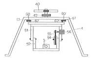
以下、本発明をその一実施例に基づいて詳細に説明する。図1は、本発明のライフライン等の施設の被災、損傷、劣化状況の空撮装置におけるラジコンヘリを示す模式図、図2は、スキッドおよび撮像装置の配設状況を示す正面図、図3は、撮像装置を搭載するフレームがOリングを介して吊下されている模様を示す平面図、図4はその側面図、図5は、ラジコンヘリの無線操縦制御システムを示すブロックダイアグラム、図6は、ラジコンヘリの無線操縦制御およびスキッドのY軸回りの回転角(θ)およびZ軸回りの回転角(ψ)の制御法を示すブロックダイアグラムである。 Hereinafter, the present invention will be described in detail based on an embodiment thereof. FIG. 1 is a schematic diagram showing a radio control helicopter in an aerial imaging device in a state of damage, damage, or deterioration of a facility such as a lifeline according to the present invention, FIG. 2 is a front view showing an arrangement state of a skid and an imaging device, and FIG. FIG. 4 is a plan view showing a pattern in which a frame on which an imaging device is mounted is suspended through an O-ring, FIG. 4 is a side view thereof, FIG. 5 is a block diagram showing a radio control control system of a radio control helicopter, FIG. These are the block diagrams which show the radio steering control of a radio control helicopter, and the control method of the rotation angle ((theta)) around the Y-axis of the skid, and the rotation angle ((psi)) around the Z-axis.
図1において、1はラジコンヘリの機体、2はメインロータ、3はテールロータ、4はスキッド、5はビデオカメラ、6はジャイロユニットである。ラジコンヘリは、メインロータ2のブレードのピッチ角をメインロータの回転角に対応させて変えることによって、メインロータブレードの回転面の傾斜を変化させて浮上、前後進、左右進せしめられる。テールロータ3は、メインロータ2の反力で機体1がZ軸回りに回転するのを防止すべく機能するとともに、機首を左右方向に変化させるべく機能する。 In FIG. 1, 1 is a radio controlled helicopter body, 2 is a main rotor, 3 is a tail rotor, 4 is a skid, 5 is a video camera, and 6 is a gyro unit. The radio control helicopter can be lifted, moved forward, and left and right by changing the inclination angle of the rotation surface of the main rotor blade by changing the pitch angle of the blade of the main rotor 2 in accordance with the rotation angle of the main rotor. The tail rotor 3 functions to prevent the
ジャイロユニット6は、機体1の進行方向(X軸)が所期の方向からずれているときの角度(ヨー角)を検出すべく機能する。機体1のX軸方向が所期の方向からずれている角度偏差があるとき、この偏差を零にすべくテールロータ3のブレードの傾き(テールロータ3の回転軸心に垂直な面とのなす角)を変えることによって、テールロータ3の回転軸心方向の推力を変化させて、ヨー角を制御する。 The gyro unit 6 functions to detect an angle (yaw angle) when the traveling direction (X axis) of the
図2において、40はフレームであって、機体1の下部に固設されている。4はスキッドであり、この実施例においては、フレーム40にベアリングを介して回転自在に吊下されている。スキッド4の頂部にはウォームホイール42が固設されており、図示しないウォームと噛合している。而してウォームは、フレーム40に配設されている、図示しないサーボモータによって回転駆動され、これによってスキッド4はZ軸回りに所期の角度だけ回転する。 In FIG. 2, reference numeral 40 denotes a frame that is fixed to the lower part of the
図3および図4において、5は撮像装置(ビデオカメラ)、51はフレームであって、Oリング60を介してスキッド4に吊下されている。このOリングによる吊下によって機体1からの振動を吸収し、撮像装置(ビデオカメラ)5の振動を小ならしめる。Oリング60はフレーム51(平面四角形)の各角隅部における突起62(断面円形の有溝)およびスキッド4のフレーム(平面四角形)の各角隅部における突起61(断面円形の有溝)にタイトに巻回されている。 3 and 4,
図2において、52は撮像装置(ビデオカメラ)搭載用フレームであり、フレーム51に枢支されていて機体1の前後からみて溝形を呈しており、フレーム51に枢支されている支点を回転中心としてY軸回りに回転自在である。撮像装置(ビデオカメラ)5はこの撮像装置(ビデオカメラ)搭載用フレーム52の幅方向(Y軸方向)中央部に配設されている台座に固定される。 In FIG. 2,
54は撮像装置(ビデオカメラ)搭載用フレーム駆動プーリ、55はタイミングベルトである。56はサーボモータであって、撮像装置(ビデオカメラ)搭載用フレーム52とフレーム51の支点における枢軸に固設されている撮像装置(ビデオカメラ)搭載用フレーム駆動プーリ54を、タイミングベルト55を介して回転駆動する。叙上の構成によって、撮像装置(ビデオカメラ)5はY軸回りにθを360°、Z軸回りにψを360°変化させることができ、ラジコンヘリの飛行或いはホバリング姿勢とは独立に所望の方向、距離で対象を撮像できる。撮像装置(ビデオカメラ)5と撮像対象間の距離の測定は、それ自体周知のレーザ測距装置によって行う。
図5に、ラジコンヘリの遠隔無線操縦システムを示す。GPSによってラジコンヘリの絶対位置を検出し、目標位置までの相対位置をレーザ等によって検出してその検出信号に基づいてメインロータ2を制御する。一方、ジャイロユニット6によって機体1のヨー角を検出し、その検出結果に基づいて、テールロタブレードの傾きを変えテールロータ3の回転軸方向の推力を操作パラメータとしてヨー角の制御を行う。本発明においては、プロポと呼ばれる、手動の操縦装置によるラジコンヘリの遠隔無線操縦を行うこともできる。 FIG. 5 shows a remote radio control system for a radio controlled helicopter. The absolute position of the radio control helicopter is detected by GPS, the relative position to the target position is detected by a laser or the like, and the main rotor 2 is controlled based on the detection signal. On the other hand, the yaw angle of the
本発明においては、GPS、電子地図を利用して、ラジコンヘリの自律飛行制御を行うこともできる。また、環境に関するセンサを搭載し、通信システムを介して遠隔地へ検知した環境情報を伝送することもできる。さらに、火災などの状況を撮像装置で捉え、搭載している消化剤等を遠隔操作によって投下するように構成することもできる。 In the present invention, autonomous flight control of a radio controlled helicopter can be performed using GPS and an electronic map. It is also possible to transmit environmental information detected to a remote place via a communication system by installing sensors related to the environment. Furthermore, it can be configured such that a situation such as a fire is captured by an imaging device, and a digestive agent or the like mounted thereon is dropped by remote control.
本発明においては、データ収集シテム、無線伝送システムもラジコンヘリに搭載される。データ収集シテムは、飛行データ、位置情報データ、画像情報などを収集するクライアントサーバである。無線伝送システムは、動画をSDHCメモリに記録するとともに、NTSC(アナログビデオ)信号として出力する。このNTSC信号をネットワークビデオサーバユニットに入力することで、動画情報をインタネットプロトコルで取り扱い可能な信号に変換する。さらに、この信号を長距離無線LAN(ラジコンヘリ搭載側)からリアルタイムの動画情報として送信し、地上側サーバの無線LANユニットで受信する。 In the present invention, a data collection system and a radio transmission system are also mounted on the radio control helicopter. The data collection system is a client server that collects flight data, position information data, image information, and the like. The wireless transmission system records moving images in an SDHC memory and outputs them as NTSC (analog video) signals. By inputting the NTSC signal to the network video server unit, the moving picture information is converted into a signal that can be handled by the Internet protocol. Further, this signal is transmitted as real-time moving image information from the long-distance wireless LAN (radio control helicopter mounting side) and received by the wireless LAN unit of the ground side server.
図6に、ラジコンヘリの無線操縦制御およびスキッドのY軸回りの回転角(θ)およびZ軸回りの回転角(ψ)の制御法を示すブロックダイアグラムを示す。メインロータ2、テールロータ3を操作端とする制御は、機体1のX、Y、Zにおける位置をGPS、レーザ測距装置によって検出し、その偏差をPID(比例積分微分制御)によって線形計画法あるいは非線形計画法で操作端を作動させることによって行われる。また、スキッド41のZ軸回りの回転角(ψ)、Y軸回りの回転角(θ)も、偏差をPID(比例積分微分制御)によって線形計画法あるいは非線形計画法で操作端を作動させることによって行われる。 FIG. 6 is a block diagram showing radio control control of the radio control helicopter and a control method of the rotation angle (θ) about the Y axis and the rotation angle (ψ) about the Z axis of the skid. Control using the main rotor 2 and tail rotor 3 as operation ends is performed by detecting the position of the
図7に、本発明のラジコンヘリの飛行制御、撮像制御、通信システム、地図データ提供サービスシステムと連動したラジコンヘリの飛行、撮像制御のための地上管理システム、空撮装置の遠隔管理システムを統合したネットワークを示す。
地上管理システムにおける入力装置110によって入力された飛行指示、撮像指示は、地上管理システム側無線通信手段108からラジコンヘリ側無線通信手段105を経由してラジコンヘリに搭載されているコンピュータ(PC)102に送信され、該コンピュータ(PC)102からラジコンヘリおよび撮像装置5へ送信される。而して、ラジコンヘリの飛行および撮像装置5を地上管理システムから制御することができる。In FIG. 7, the radio control helicopter flight control, imaging control, communication system, radio control helicopter flight linked to the map data providing service system of the present invention, the ground management system for imaging control, and the aerial imaging device remote management system are integrated. Network
The flight instruction and the imaging instruction input by the input device 110 in the ground management system are sent from the ground management system side wireless communication means 108 via the radio control helicopter side wireless communication means 105 to the computer (PC) 102 mounted on the radio control helicopter. And transmitted from the computer (PC) 102 to the radio control helicopter and the
地上管理システムにおけるコンピュータ(PC)107は、位置座標データ取得手段(GPS)が取得した位置座標データをラジコンヘリに搭載されているコンピュータ(PC)と、ラジコンヘリ側無線通信手段105および地上管理システム側無線通信手段108を介して受信し、通信手段111と公衆通信網113を介して地図データサービス(Google map等)114へ送信する。 The computer (PC) 107 in the ground management system includes a computer (PC) in which the position coordinate data acquired by the position coordinate data acquisition means (GPS) is mounted on the radio control helicopter, the radio control helicopter side wireless communication means 105, and the ground management system. It is received via the side wireless communication means 108 and transmitted to the map data service (such as Google map) 114 via the communication means 111 and the public communication network 113.
地図データサービス(Google map等)114は、送信された位置座標データを含む地図データおよび当該地図の範囲の航空写真または衛星写真を返信し、地上管理システムにおけるコンピュータ(PC)107がそれを受信し、当該地図の範囲の航空写真または衛星写真上に空撮装置に対する飛行軌跡、飛行指示、撮影完了範囲、動画像撮像指示範囲などを重畳させて地上管理システムにおける表示装置109に表示する。また、重畳された画面において、入力装置110を用いて新たな飛行指示または動画像撮像指示を入力することができる。The map data service (Google map, etc.) 114 sends back the map data including the transmitted position coordinate data and the aerial photograph or satellite photograph of the range of the map, and the computer (PC) 107 in the ground management system receives it. The flight trajectory, flight instruction, imaging completion range, moving image imaging instruction range, etc. for the aerial imaging apparatus are superimposed on the aerial photograph or satellite photograph of the map range and displayed on the display device 109 in the ground management system. In addition, a new flight instruction or moving image capturing instruction can be input using the input device 110 on the superimposed screen.
遠隔地に配置されたコンピュータ115は、位置座標データ取得手段103が取得した位置座標データ等を地上管理システム112および公衆通信網113ならびに通信手段116を介して地図データサービス(Google map等)114へ送信する。地図データサービス(Google map等)114は送信された位置座標データを含む地図データおよび当該地図の範囲の航空写真または衛星写真を返信し、遠隔地に配置されたコンピュータ115がそれを受信し、当該地図の範囲の航空写真または衛星写真上に空撮装置に対する飛行軌跡、飛行指示、撮影完了範囲、動画像撮像指示範囲などを重畳させて地上管理システムにおける表示装置117に表示する。また、重畳された画面において、入力装置118を用いて新たな飛行指示または動画像撮像指示を入力することができる。 The computer 115 disposed at a remote location transfers the position coordinate data acquired by the position coordinate data acquisition means 103 to the map data service (Google map, etc.) 114 via the ground management system 112, the public communication network 113, and the communication means 116. Send. The map data service (such as Google map) 114 sends back the map data including the transmitted position coordinate data and the aerial photograph or satellite photograph of the range of the map, and the computer 115 located at the remote location receives it, and The flight trajectory, flight instruction, imaging completion range, moving image imaging instruction range, etc. for the aerial imaging apparatus are superimposed on the aerial photograph or satellite photograph of the map range and displayed on the display device 117 in the ground management system. In addition, a new flight instruction or moving image capturing instruction can be input using the input device 118 on the superimposed screen.
1 機体
2 メインロータ
3 テールロータ
4 スキッド
5 撮像装置(ビデオカメラ)
6 ジャイロユニット
40 フレーム
42 ウォームホイール
51 フレーム
52 撮像装置(ビデオカメラ)搭載用フレーム
53 支点
54 撮像装置(ビデオカメラ)搭載用フレーム駆動プーリ
55 タイミングベルト
56 駆動用サーボモータ
60 Oリング
61 Oリング巻回突起(スキッド側)
62 Oリング巻回突起(撮像装置(ビデオカメラ)搭載用フレーム側)
101 ラジコンヘリ
102 ラジコンヘリ搭載コンピュータ(PC)
103 位置座標データ取得手段
104 動画像取得手段
105 ラジコンヘリに搭載の無線通信手段
106 空撮装置
107 地上管理システムにおけるコンピュータ(PC)
108 地上管理システムにおける無線通信手段
109 地上管理システムにおける表示装置
110 地上管理システムにおける入力装置
111 地上管理システムにおける通信手段
112 地上管理システム
113 公衆通信網
114 地図データ提供サービス(Google map等)
115 遠隔管理システムに配置されたコンピュータ
116 遠隔管理システムにおける通信手段
117 遠隔管理システムにおける表示装置
118 遠隔管理システムにおける入力装置
119 ラジコンヘリ遠隔管理システムDESCRIPTION OF
6 Gyro unit 40
62 O-ring winding protrusion (frame side for mounting imaging device (video camera))
101 Radio controlled
DESCRIPTION OF SYMBOLS 103 Position coordinate data acquisition means 104 Moving image acquisition means 105 Radio | wireless communication means mounted in radio controlled helicopter 106 Aerial imaging device 107 Computer (PC) in ground management system
108 Wireless communication means in ground management system 109 Display device in ground management system 110 Input device in ground management system 111 Communication means in ground management system 112 Ground management system 113 Public communication network 114 Map data providing service (Google map, etc.)
115 Computer Arranged in Remote Management System 116 Communication Means in Remote Management System 117 Display Device in Remote Management System 118 Input Device in Remote Management System 119 Radio Control Helicopter Remote Management System
Claims (1)
Translated fromJapanesePriority Applications (1)
| Application Number | Priority Date | Filing Date | Title |
|---|---|---|---|
| JP2008163937AJP2010006089A (en) | 2008-06-24 | 2008-06-24 | Aerial photographing device of disaster-stricken, damaged and deteriorated state of facility such as for lifeline |
Applications Claiming Priority (1)
| Application Number | Priority Date | Filing Date | Title |
|---|---|---|---|
| JP2008163937AJP2010006089A (en) | 2008-06-24 | 2008-06-24 | Aerial photographing device of disaster-stricken, damaged and deteriorated state of facility such as for lifeline |
Publications (1)
| Publication Number | Publication Date |
|---|---|
| JP2010006089Atrue JP2010006089A (en) | 2010-01-14 |
Family
ID=41587085
Family Applications (1)
| Application Number | Title | Priority Date | Filing Date |
|---|---|---|---|
| JP2008163937APendingJP2010006089A (en) | 2008-06-24 | 2008-06-24 | Aerial photographing device of disaster-stricken, damaged and deteriorated state of facility such as for lifeline |
Country Status (1)
| Country | Link |
|---|---|
| JP (1) | JP2010006089A (en) |
Cited By (16)
| Publication number | Priority date | Publication date | Assignee | Title |
|---|---|---|---|---|
| JP2012025216A (en)* | 2010-07-21 | 2012-02-09 | Kawasaki Heavy Ind Ltd | Flight control system and flight control method for unmanned flying body using millimeter wave |
| JP2013038622A (en)* | 2011-08-09 | 2013-02-21 | Topcon Corp | Remote control system |
| JP2014126468A (en)* | 2012-12-26 | 2014-07-07 | Kawasaki Heavy Ind Ltd | Laser irradiation system using relay machine |
| CN104061905A (en)* | 2014-06-16 | 2014-09-24 | 江苏恒创软件有限公司 | Aerial photographing device and ground target height measuring method based on unmanned helicopter |
| JP2015146371A (en)* | 2014-02-03 | 2015-08-13 | 江田特殊防水工業株式会社 | Solar panel fault diagnosis system, solar panel fault diagnosis method, and radio-controlled helicopter for solar panel fault diagnosis |
| JP2017504863A (en)* | 2014-07-31 | 2017-02-09 | エスゼット ディージェイアイ テクノロジー カンパニー リミテッドSz Dji Technology Co.,Ltd | System and method for virtual sightseeing using unmanned aerial vehicles |
| CN106556957A (en)* | 2015-09-29 | 2017-04-05 | 日本电产三协株式会社 | Filming apparatus |
| JP2017078575A (en)* | 2015-10-19 | 2017-04-27 | エナジー・ソリューションズ株式会社 | Checkup system, and checkup method |
| JP2017158116A (en)* | 2016-03-03 | 2017-09-07 | キヤノン株式会社 | Imaging control apparatus and control method thereof |
| JP2018030461A (en)* | 2016-08-25 | 2018-03-01 | 光司商会株式会社 | Rotary wing flight body and remote control system therefor |
| JP2018514002A (en)* | 2015-03-23 | 2018-05-31 | ハリー ポッター インベストメンツ リミティド ライアビリティ カンパニー | Camera rig |
| CN108688802A (en)* | 2017-04-06 | 2018-10-23 | 东北林业大学 | A kind of unmanned plane that can measure trees height |
| CN108860634A (en)* | 2018-05-22 | 2018-11-23 | 吉林大学 | A kind of Novel helicopter carrying detection instrument connecting platform |
| JP2019053703A (en)* | 2017-09-13 | 2019-04-04 | 敏幸 因幡 | Autonomous flight robot system that starts automatically at the disaster site |
| JP2020080553A (en)* | 2014-10-17 | 2020-05-28 | ソニー株式会社 | Control device, control method, and flight device |
| JP2020083296A (en)* | 2019-04-26 | 2020-06-04 | 有限会社渥美不動産アンドコーポレーション | Flight vehicle |
- 2008
- 2008-06-24JPJP2008163937Apatent/JP2010006089A/enactivePending
Cited By (21)
| Publication number | Priority date | Publication date | Assignee | Title |
|---|---|---|---|---|
| JP2012025216A (en)* | 2010-07-21 | 2012-02-09 | Kawasaki Heavy Ind Ltd | Flight control system and flight control method for unmanned flying body using millimeter wave |
| JP2013038622A (en)* | 2011-08-09 | 2013-02-21 | Topcon Corp | Remote control system |
| JP2014126468A (en)* | 2012-12-26 | 2014-07-07 | Kawasaki Heavy Ind Ltd | Laser irradiation system using relay machine |
| JP2015146371A (en)* | 2014-02-03 | 2015-08-13 | 江田特殊防水工業株式会社 | Solar panel fault diagnosis system, solar panel fault diagnosis method, and radio-controlled helicopter for solar panel fault diagnosis |
| CN104061905A (en)* | 2014-06-16 | 2014-09-24 | 江苏恒创软件有限公司 | Aerial photographing device and ground target height measuring method based on unmanned helicopter |
| JP2017504863A (en)* | 2014-07-31 | 2017-02-09 | エスゼット ディージェイアイ テクノロジー カンパニー リミテッドSz Dji Technology Co.,Ltd | System and method for virtual sightseeing using unmanned aerial vehicles |
| US10140874B2 (en) | 2014-07-31 | 2018-11-27 | SZ DJI Technology Co., Ltd. | System and method for enabling virtual sightseeing using unmanned aerial vehicles |
| JP2020080553A (en)* | 2014-10-17 | 2020-05-28 | ソニー株式会社 | Control device, control method, and flight device |
| US11530050B2 (en) | 2014-10-17 | 2022-12-20 | Sony Corporation | Control device, control method, and flight vehicle device |
| US11884418B2 (en) | 2014-10-17 | 2024-01-30 | Sony Group Corporation | Control device, control method, and flight vehicle device |
| JP2018514002A (en)* | 2015-03-23 | 2018-05-31 | ハリー ポッター インベストメンツ リミティド ライアビリティ カンパニー | Camera rig |
| CN106556957A (en)* | 2015-09-29 | 2017-04-05 | 日本电产三协株式会社 | Filming apparatus |
| JP2017067878A (en)* | 2015-09-29 | 2017-04-06 | 日本電産サンキョー株式会社 | Image pickup apparatus |
| JP2017078575A (en)* | 2015-10-19 | 2017-04-27 | エナジー・ソリューションズ株式会社 | Checkup system, and checkup method |
| JP2017158116A (en)* | 2016-03-03 | 2017-09-07 | キヤノン株式会社 | Imaging control apparatus and control method thereof |
| JP2018030461A (en)* | 2016-08-25 | 2018-03-01 | 光司商会株式会社 | Rotary wing flight body and remote control system therefor |
| CN108688802A (en)* | 2017-04-06 | 2018-10-23 | 东北林业大学 | A kind of unmanned plane that can measure trees height |
| JP2019053703A (en)* | 2017-09-13 | 2019-04-04 | 敏幸 因幡 | Autonomous flight robot system that starts automatically at the disaster site |
| CN108860634B (en)* | 2018-05-22 | 2021-07-06 | 吉林大学 | A new type of helicopter equipped with a detection instrument connection platform |
| CN108860634A (en)* | 2018-05-22 | 2018-11-23 | 吉林大学 | A kind of Novel helicopter carrying detection instrument connecting platform |
| JP2020083296A (en)* | 2019-04-26 | 2020-06-04 | 有限会社渥美不動産アンドコーポレーション | Flight vehicle |
Similar Documents
| Publication | Publication Date | Title |
|---|---|---|
| JP2010006089A (en) | Aerial photographing device of disaster-stricken, damaged and deteriorated state of facility such as for lifeline | |
| EP2772725B1 (en) | Aerial Photographing System | |
| JP6658532B2 (en) | Control device, control method, and flying object device | |
| JP6151902B2 (en) | Camera for photo measurement and aerial photographic equipment | |
| US8953933B2 (en) | Aerial photogrammetry and aerial photogrammetric system | |
| JP2006027448A (en) | Aerial imaging method and apparatus using unmanned air vehicle | |
| TWI496605B (en) | Unmanned aerial vehicle, surveillance method and surveillance device | |
| EP3108318B1 (en) | System and method for data recording and analysis | |
| CN110944909B (en) | Rotorcraft | |
| JP6262318B1 (en) | Cable inspection device | |
| JP2015223995A (en) | Unmanned flight body for photographing | |
| US20090132100A1 (en) | Flight Control System | |
| JP2006027331A (en) | How to collect aerial video information using unmanned air vehicles | |
| JP2006082774A (en) | Unmanned air vehicle and unmanned air vehicle control method | |
| CN109665099B (en) | Unmanned aerial vehicle and overhead line shooting method | |
| US20220335840A1 (en) | Ruggedized autonomous helicopter platform | |
| JP7362203B2 (en) | unmanned moving body | |
| CN107624171A (en) | The control method of unmanned plane and control UAV Attitude, control device | |
| CN111953892A (en) | Unmanned aerial vehicle, inspection method, and inspection program | |
| KR20120082728A (en) | A line of sight interlocker of airborne camera gimbal for aerial chasing photograph | |
| JP4532318B2 (en) | Unmanned helicopter | |
| JP7187998B2 (en) | Inspection system, inspection support method and inspection support program | |
| US20240327044A1 (en) | Unmanned aerial vehicle suspended propulsion systems and methods | |
| JP2005289127A (en) | Attitude position control system and attitude position control device for flying device | |
| CN118062282A (en) | Unmanned aerial vehicle loading platform for fan blade inspection |
Legal Events
| Date | Code | Title | Description |
|---|---|---|---|
| A621 | Written request for application examination | Free format text:JAPANESE INTERMEDIATE CODE: A621 Effective date:20110623 | |
| A072 | Dismissal of procedure [no reply to invitation to correct request for examination] | Free format text:JAPANESE INTERMEDIATE CODE: A073 Effective date:20121102 |