JP2010004941A - Cylindrical member and multiple clip application apparatus - Google Patents
Cylindrical member and multiple clip application apparatusDownload PDFInfo
- Publication number
- JP2010004941A JP2010004941AJP2008164687AJP2008164687AJP2010004941AJP 2010004941 AJP2010004941 AJP 2010004941AJP 2008164687 AJP2008164687 AJP 2008164687AJP 2008164687 AJP2008164687 AJP 2008164687AJP 2010004941 AJP2010004941 AJP 2010004941A
- Authority
- JP
- Japan
- Prior art keywords
- clip
- sheath
- skirt
- portions
- clips
- Prior art date
- Legal status (The legal status is an assumption and is not a legal conclusion. Google has not performed a legal analysis and makes no representation as to the accuracy of the status listed.)
- Ceased
Links
Images


Classifications
- A—HUMAN NECESSITIES
- A61—MEDICAL OR VETERINARY SCIENCE; HYGIENE
- A61B—DIAGNOSIS; SURGERY; IDENTIFICATION
- A61B17/00—Surgical instruments, devices or methods
- A61B2017/00526—Methods of manufacturing
- A61B2017/0053—Loading magazines or sutures into applying tools
Landscapes
- Surgical Instruments (AREA)
Abstract
Description
Translated fromJapanese本発明は、生体内等で止血や傷口の閉塞等を行うクリップ処置具に用いられる筒状部材と、止血や傷口の閉塞等のクリップ処置を連続して行うことができる連発式クリップ処置具とに関する。 The present invention relates to a cylindrical member used for a clip treatment instrument that performs hemostasis and wound closure in a living body, and a continuous clip treatment instrument that can continuously perform clip treatment such as hemostasis and wound closure. About.
クリップ処置具は、内視鏡の鉗子チャンネルを通じて生体内に挿入され、その先端からクリップを突出させ、出血部や病変組織を除去した部位といった患部をクリップで挟み、止血や傷口の閉塞等を行うクリップ処置に用いられる。特許文献1に記載されているように、クリップ処置具は、操作ワイヤが挿通されたシースを有しており、クリップは操作ワイヤに連結された状態でシース内に装填される。 The clip treatment tool is inserted into the living body through the forceps channel of the endoscope, the clip protrudes from the tip, the affected part such as the site where the bleeding part or the lesioned tissue has been removed is sandwiched between the clips, and hemostasis or wound closure is performed. Used for clip treatment. As described in Patent Document 1, the clip treatment tool has a sheath through which an operation wire is inserted, and the clip is loaded into the sheath while being connected to the operation wire.
特許文献1には、クリップの先端部分を締め付けて、先端の爪部を閉じた状態にする押さえ管が記載されている。押さえ管は、クリップの後端に装着された状態でクリップとともにシース内に装填され、クリップ処置の際にクリップに対して前進して、クリップの先端部分を締め付ける。押さえ管の外周面には、シース内では閉じ、クリップとともにシース内から押し出されたときに、弾性により半径方向に突出するように開き、シースの先端と係合することによりクリップの後退を防止するスカート部が設けられている。 Patent Document 1 describes a holding tube that tightens the tip of a clip and closes the claw at the tip. The holding tube is loaded into the sheath together with the clip in a state of being attached to the rear end of the clip, and is advanced with respect to the clip during the clip treatment to tighten the distal end portion of the clip. The outer surface of the holding tube is closed in the sheath, and when it is pushed out of the sheath together with the clip, it opens so as to protrude in the radial direction by elasticity, and prevents the clip from retreating by engaging with the distal end of the sheath. A skirt is provided.
上記特許文献1に記載されたクリップ装置を始め、従来用いられているクリップ処置具は、操作ワイヤの先端に1つのクリップのみが取り付けられたもので、一回のクリップ処置を行うごとにシース全体を内視鏡から引き出し、次のクリップをセットして再びシースを内視鏡内に挿入して、次のクリップ処置を行うという煩瑣な作業が必要となっている。 The clip treatment tool conventionally used including the clip device described in the above-mentioned Patent Document 1 is such that only one clip is attached to the tip of the operation wire, and the entire sheath is performed each time a clip treatment is performed. It is necessary to carry out a cumbersome work of pulling out from the endoscope, setting the next clip, inserting the sheath into the endoscope again, and performing the next clip treatment.
これに対し、連続的なクリップ処置を可能にする連発式クリップ処置具が提案されている。例えば、特許文献2には、前方に配されたクリップの後端部分に形成された連結孔に、後方に配されたクリップの先端の爪部を係合させることにより、複数のクリップが90度ずつ交互に向きを変えて直接連結されるようにした連発式クリップ処置具が記載されている。 On the other hand, a repetitive clip treatment tool that enables continuous clip treatment has been proposed. For example, Patent Document 2 discloses that a plurality of clips are 90 degrees by engaging a claw portion at the front end of a clip disposed rearward with a connecting hole formed in a rear end portion of a clip disposed forward. A repetitive clip treatment device is described in which the directions are alternately changed and connected directly.
しかし、特許文献2の連発式クリップ処置具は、前後のクリップの係合のみでクリップの連結を維持しており、その連結部が剥き出しになっている。そのため、連結状態が不安定であり、内視鏡への挿入時に、湾曲部を通過するときに外れてしまう可能性がある。また、連結部に無理な力がかかることにより使用前のクリップにこじれや歪みを生じることも考えられる。 However, the continuous-type clip treatment tool of Patent Document 2 maintains the clip connection only by engaging the front and rear clips, and the connection portion is exposed. For this reason, the connected state is unstable, and when inserted into the endoscope, it may come off when passing through the bending portion. It is also conceivable that an unreasonable force is applied to the connecting portion, causing the clip before use to be twisted or distorted.
本発明者は、特許文献2の連発式クリップ処置具の問題点を解消するため、新たな構成の連発式クリップ処置具を研究し、開発している。この連発式クリップ処置具は、開閉自在な先端の爪部と閉じた後端部を互いに係合させて1列に連結した複数のクリップと、各クリップの外側に装着され、後方に配されたクリップの爪部を覆って連結状態を維持する複数の連結リングとを備えている。筒状部材である連結リングは、特許文献1の押さえ管と同様にスカート部を有しており、クリップに対して前進したときに、その先端部分でクリップの先端部分を締めつけて爪部を閉じる機能も有している。 The present inventor has researched and developed a repetitive clip treatment device having a new configuration in order to solve the problems of the repetitive clip treatment device of Patent Document 2. This repetitive clip treatment device is provided with a plurality of clips that are connected to each other in a row by engaging a claw portion at the front end that can be freely opened and closed and a rear end portion that is closed, and is arranged on the outside of each clip and arranged rearward A plurality of coupling rings that cover the claw portions of the clip and maintain the coupling state. The connecting ring, which is a cylindrical member, has a skirt portion similar to the holding tube of Patent Document 1, and when the head advances with respect to the clip, the tip portion of the clip is tightened at the tip portion to close the claw portion. It also has a function.
クリップと連結リングには、両者の位置ずれを防止する工夫が施されている。例えば、スカート部が外側から押されて閉じたときに、連結リング内のクリップをスカート部で押圧して保持するようにしている。 The clip and the connecting ring are devised to prevent the positional deviation between them. For example, when the skirt portion is pushed from the outside and closed, the clip in the connecting ring is pressed and held by the skirt portion.
複数のクリップ及び連結リングは、予め連結させた状態でケース等に収容しておき、このケースから、または装填用の治具を介して、シース内に装填することが考えられている。ケース、または治具には、シースの内径面と同じ径を有するスカート閉じ通路が設けられており、スカート閉じ通路を通過してスカート部が閉じられた連結リングを、その後端側からシースの先端内に装填する。
シースの内径は、その内部で連結リングを移動させるため、連結リングの外径よりもわずかに大きくなっている。そのため、シースの内径と同じ径を有するスカート閉じ通路内でスカート部を閉じても、スカート部の後端側のエッジは、連結リングの外周面からわずかに突出するので、シースの先端に引っ掛かることがある。 The inner diameter of the sheath is slightly larger than the outer diameter of the connection ring in order to move the connection ring within the sheath. Therefore, even if the skirt portion is closed in the skirt closing passage having the same diameter as the inner diameter of the sheath, the edge on the rear end side of the skirt portion slightly protrudes from the outer peripheral surface of the connecting ring, so that it is caught on the distal end of the sheath. There is.
また、シースの内径面と連結リングの外周面との間の摩擦が大きい場合、シース内での連結クリップユニットの移動に支障を生じることがあった。 In addition, when the friction between the inner diameter surface of the sheath and the outer peripheral surface of the connection ring is large, the movement of the connection clip unit within the sheath may be hindered.
また、シース内でクリップと連結リングとの位置ずれを防止するため、スカート部によるクリップの押し付け力を向上させることが望まれている。 In addition, it is desired to improve the pressing force of the clip by the skirt portion in order to prevent displacement of the clip and the connection ring within the sheath.
本発明の目的は、クリップとともに連結リングをシースに装填する際に、スカート部がシースに引っ掛からないように確実に閉じることにある。また、シース内での連結リングの移動をスムーズにするとともに、スカート部によるクリップの保持力を向上させることも本発明の目的に含まれる。 An object of the present invention is to securely close the skirt portion so that the skirt portion is not caught by the sheath when the coupling ring is loaded onto the sheath together with the clip. Further, it is included in the object of the present invention to make the movement of the connecting ring within the sheath smooth and improve the holding force of the clip by the skirt portion.
本発明の筒状部材は、開閉自在な爪部を先端に有するクリップとともにシースに装填されている。筒状部材には、シース内では内側に閉じ、シースの先端通過後にシースの内径よりも広幅に開いてシース内への後退を阻止するスカート部と、スカート部に形成され、スカート部が閉じたときにシースの内径面と当接する凸部と、スカート部がシースの先端を通過して開いたときに、後端側から挿入されたクリップの先端側を締め付けて、爪部を閉じる締付穴とを備えている。 The cylindrical member of the present invention is loaded in a sheath together with a clip having a claw that can be freely opened and closed at the tip. The tubular member is formed in the skirt portion, which is closed to the inside in the sheath, opens wider than the inner diameter of the sheath after passing through the distal end of the sheath and prevents retreat into the sheath, and the skirt portion is closed. Tightening hole that closes the claw by tightening the tip side of the clip inserted from the rear end side when the skirt part opens through the tip of the sheath, and the convex part that sometimes contacts the inner diameter surface of the sheath And.
本発明の筒状部材は、複数のクリップが先端の爪部と閉じた後端とを互いに連結させて1列に連結したときに、装着されているクリップの後端に係合しているクリップの爪部を覆って、クリップの連結状態を維持する保持部を有している。 The cylindrical member of the present invention is a clip in which a plurality of clips are engaged with a rear end of a clip that is mounted when a front end claw portion and a closed rear end are connected to each other and connected in a row. A holding portion that covers the claw portion and maintains the clip connected state.
本発明の筒状部材は、締付穴を利用してクリップの外側に装着されている。スカート部は、閉じたときに筒状部材内のクリップを押圧して保持する。 The cylindrical member of the present invention is attached to the outside of the clip using a fastening hole. The skirt portion presses and holds the clip in the cylindrical member when closed.
凸部は、筒状部材がシース内で移動する方向に沿って円弧状に突出しているので、凸部とシースとの摩擦力を小さくすることができる。更に、スカート部は、周方向に複数設けられている。 Since the convex portion protrudes in an arc shape along the direction in which the cylindrical member moves in the sheath, the frictional force between the convex portion and the sheath can be reduced. Further, a plurality of skirt portions are provided in the circumferential direction.
本発明の連発式クリップ処置具は、円筒状のシースと、1列に並べて連結した複数のクリップと、上述した複数の筒状部材と、シース内で最後尾のクリップに連結し、複数のクリップを牽引する操作ワイヤとを備えている。 The continuous clip treatment device of the present invention is connected to a cylindrical sheath, a plurality of clips connected in a line, a plurality of cylindrical members described above, and a clip at the end in the sheath. And an operation wire for pulling.
本発明は、スカート部が閉じたときに筒状の部材の外周面から突出してシースの内径面と当接する凸部を設けている。すなわち、凸部を押圧すれば、スカート部が筒状部材の外周面から突出しないように閉じさせることができる。これにより、筒状部材をクリップとともにシースに装填する際に、スカート部がシースの先端に引っ掛かるのを防止することができる。 In the present invention, when the skirt portion is closed, a convex portion that protrudes from the outer peripheral surface of the cylindrical member and contacts the inner diameter surface of the sheath is provided. That is, if the convex portion is pressed, the skirt portion can be closed so as not to protrude from the outer peripheral surface of the cylindrical member. Thereby, when loading a cylindrical member with a clip to a sheath, it can prevent that a skirt part is caught in the front-end | tip of a sheath.
また、シース内に装填した筒状部材は、凸部がシースの内径面に点接触するので、シースとの間の摩擦力を小さくすることができる。これにより、シース内での筒状部材の移動がスムーズになる。更に、シース内では、スカート部よりも外側に突出した凸部をシースで押圧してスカート部を閉じているので、スカート部によるクリップの挟持力を向上させて、クリップと筒状部材との位置ずれを防止することができる。 Further, since the convex portion of the cylindrical member loaded in the sheath makes point contact with the inner diameter surface of the sheath, the frictional force with the sheath can be reduced. Thereby, the movement of the cylindrical member within the sheath becomes smooth. Further, in the sheath, the convex portion protruding outward from the skirt portion is pressed by the sheath and the skirt portion is closed, so that the holding force of the clip by the skirt portion is improved and the position of the clip and the cylindrical member is increased. Deviation can be prevented.
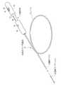
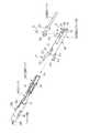
本発明の連発式クリップ処置具について説明する。図1に示すように、連発式クリップ処置具(以下、クリップ処置具と呼ぶ)10は、シース11、操作ワイヤ12、連結クリップユニット13、操作部14を備えている。 The continuous clip treatment tool of the present invention will be described. As shown in FIG. 1, a repetitive clip treatment tool (hereinafter referred to as a “clip treatment tool”) 10 includes a
シース11は、長尺の筒状体であり、可撓性を有している。操作ワイヤ12は、シース11内に進退自在に挿通されている。連結クリップユニット13は、1列に連結した複数個のクリップを備えている。連結クリップユニット13は、シース11の先端部内に装填され、その後端が操作ワイヤ12の先端に連結する。操作部14は、シース11と操作ワイヤ12の後端にそれぞれ接続されており、これらの牽引操作に用いられる。連結クリップユニット13の各クリップは、シース11が牽引されることにより、シース11の先端から1個ずつ押し出される。シース11から押し出されて開いたクリップは、操作ワイヤ12が牽引されることにより閉じられる。 The
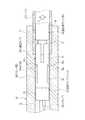
図2(A)は、連結クリップユニット13が装填されたシース11の先端部分の断面図であり、先頭のクリップによるクリップ処置の動作開始直前の状態を示している。同図(B)は、同図(A)と90度異なる角度から見た断面図である。 FIG. 2A is a cross-sectional view of the distal end portion of the
連結クリップユニット13は、1列に連結された複数個の止血クリップ体17(17A〜17C)と、最後尾の止血クリップ体17Cに連結された連結用クリップ体18から構成されている。止血クリップ体17は、クリップ19(19A〜19C)と、クリップ19の外側に装着された筒状の連結リング20(20A〜20C)とを備えている。複数個の止血クリップ体17は、前方に配されたクリップ19の後端に後方のクリップ19が係合することにより1列に連結している。 The
図3に示すように、クリップ19は、一枚の細長い板を180度湾曲させて閉塞端を作った後、その両片を交差させ、かつ2つの開放端が対向するように屈曲させて爪部23,23を形成している。クリップ19は、細長い板を交差させた交差部24を境にして、開放端側が腕部25,25であり、閉塞端側がターン部26である。腕部25,25の中央部分には、部分的に広幅とされた凸部27,27が形成されている。 As shown in FIG. 3, the clip 19 is formed by bending a single elongated plate 180 degrees to form a closed end, crossing the two pieces, and bending the two open ends to oppose each other.
クリップ19は、腕部25,25に外力が加えられていないときに、爪部23,23が離れた開放状態となる。また、腕部25,25が互いに接近するように弾性変形したときに、爪部23,23が噛合して、クリップ処置の対象となる患部挟む閉じ状態となる。爪部23,23は、患部を確実に挟むために、V字のオス型とメス型に形成されている。クリップ19には、生体適合性のある金属を用いることができ、例えば、ばね用ステンレス鋼であるSUS631を用いることができる。 The clip 19 is in an open state in which the
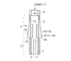
図3に示すように、筒状部材である連結リング20は、略円筒形状であり、中央の穴にクリップ19のターン部26が挿入されて、クリップ19の外側に装着されている。連結リング20は、外径がシース11の内径とほぼ等しく、その構成の大部分がフレキシブル性を有するプラスチックで形成されているので、屈曲されたシース11内をスムーズに進退移動することができる。 As shown in FIG. 3, the connecting
連結リング20は、爪部23,23を閉じ状態に変位させる締付部30と、クリップ19の連結状態を維持する保持部31とを備えている。締付部30は、保持部31の先端に嵌合された金属製の円筒状部品である。締付部30には、クリップ19の交差部24近傍の幅よりも大きく、凸部27の幅よりも小さい内径の締付穴30aが形成されている。締付部30には、生体適合性のある金属が用いられ、例えばステンレス鋼SUS304を用いることができる。 The
締付部30は、連結リング20がクリップ19の外側に装着されたときに、交差部24を覆う初期位置に配置される。腕部25,25は、締付部30が初期位置にあるときに開放状態となる。締付部30が初期位置から凸部27に当接する位置まで移動すると、締付穴30aによって腕部25,25が押圧され、爪部23,23が閉じる。爪部23,23は、腕部25,25が締め付けられることにより、所定の噛合力を発揮する。 The tightening
図4に示すように、保持部31は、内部にクリップ19のターン部26及び腕部25,25が収容可能な穴31aが形成された略円筒形状である。保持部31は、先端側に配された第1領域34と、基端側に配された第2領域35とを有している。 As shown in FIG. 4, the holding
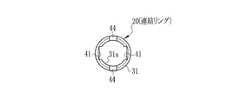
第1領域34には、先端側から後端側に向かってスカート状に広がり、保持部31の外周面から半径方向に突出するスカート部38が形成されている。スカート部38は、先端側が保持部31に弾性自在に接続し、後端側が保持部31から切り離されていて、外力が加えられていないときには外側に広がるように開き、外側から押されたときに保持部31内(穴31a内)に入り込むようにして閉じる。スカート部38は、保持部33の長手方向において同じ位置で、かつ周方向で180°離れた位置に2つ設けられている。 In the
スカート部38,38の外周面には、半径方向に突出された凸部38a,38aが設けられている。凸部38a,38aは、連結リング20がシース11内で移動する方向に沿って円弧状に突出している。凸部38a,38aは、連結リング20がその後端側からシース11の先端に装填される際に、スカート部38、38の後端側のエッジ38bがシース11の先端に引っ掛からないように、スカート部38、38を閉じる。また、凸部38a,38aは、連結リング20がシース11内にあるときに、シース11の内壁面と当接して摩擦を小さくして、連結クリップユニット13のシース11内での移動をスムーズにする。 On the outer peripheral surface of the
図5に示すように、第2領域35の穴31a内には、周方向においてスカート部38と同じ位置に、2つの溝(凹部)41が対向するように形成されている。溝41,41の幅(開口幅)は、クリップ19の腕部25の最大幅よりわずかに大きく、凸部27の幅よりも小さい。一方の溝41の壁面から他方の溝41の壁面までの距離は、クリップ19の2つの爪部23,23の長さ(拡開方向の長さ)を足し合わせた長さにほぼ等しい。 As shown in FIG. 5, two grooves (concave portions) 41 are formed in the
第2領域35の領域長さは、クリップ19の初期位置に配された締付部30が、クリップ19の先端側に移動されて凸部27に当接する距離、すなわち、クリップ19の締め付けを完了するまでに要する移動長さとほぼ等しい長さを有している。また、第2領域35の領域長さは、クリップ19の爪部23,23から凸部27の上端までの長さともほぼ等しい。 The region length of the
第2領域35には、周方向においてスカート部38,38から90°ずれた2箇所に、スリット44,44が形成されている。スリット44,44は、連結リング20のフレキシブル性を向上させる。また、スリット44によって連結リング20の後端部を開くことにより、連結リング20内での2つのクリップ19の係合が行いやすくなる。保持部31には、生体適合性があり、かつ、スカート部38に要求される弾性および剛性を満たす材料が用いられる。このような保持部31の材料としては、例えば、PPSU(ポリフェニルサルホン、polyphenylsulfone)を用いることができる。 In the
図2に示す連結リング20Aのように、第1領域34には、締付穴30aからクリップ19Aのターン部26が挿入される。クリップ19Aは、爪部23,23の開閉方向がスカート部38の開閉方向と90°ずれるように回転されている。連結リング20Aは、締付部30がクリップ19の交差部24を覆う初期位置にセットされるように、クリップ19Aの外側に装着される。第1領域34内のクリップ19Aは、初期位置にセットされたときに、ターン部26の後端が第2領域35内に突出する。また、連結リング20Aの外に突出している腕部25,25は、開放状態となる。 Like the connecting
連結リング20Aの第2領域35には、穴31aの後端側から別のクリップ19Bの腕部25,25が挿入される。このクリップ19Bは、第1領域34内のクリップ19Aに対して、腕部25,25の開閉方向が90°ずれるように回転されているので、腕部25,25が溝41,41に挿入される。第2領域35に挿入されたクリップ19Bは、先端側のクリップ19Aのターン部26に爪部23,23が係合する。連結リング20Aは、第2領域35内のクリップ19Bの爪部23,23が、開放状態に変位しないように抑えて、2つのクリップ19A,19Bの連結状態を維持する。 The
連結リング20は、シース11内に装填されたときに、図2(B)に示す連結リング20Bのように、スカート部38,38がシース11に押されて閉じている。閉じたスカート部38,38は、その内面でクリップ19Bのターン部26の側面を挟み込む。これにより、連結リング20Bとクリップ19Bとが一体化するので、クリップ19と連結リング20との間に、回転方向及び進退方向でのずれが生じない。なお、スカート部38,38の表面に設けた凸部38a,38aがシース11の内径面に当接するので、スカート部38,38によるクリップ19の挟持力をより強くすることができる。 When the connecting
連結リング20Bの第2領域35に挿入されたクリップ19Cは、腕部25,25が溝41,41に係合し、爪部23,23が第1領域34内のクリップ19Bに係合し、凸部27,27が連結リング20Bの後端に当接することにより、連結リング20Bに対する回転移動及び進退移動が抑えられている。これにより、シース11内に装填された連結クリップユニット13は、各クリップ19及び連結リング20にずれを生じさせることなく、シース11内を進退移動、及び回転移動することができる。 The
図2(B)に示す連結リング20Aのように、連結リング20がシース11の先端から押し出されたときには、スカート部38が自身の弾性によって外側に開き、シース11の内径よりも広幅となって、連結リング20Aのシース11内への後退を阻止する。第1領域34内のクリップ19Aは、スカート部38による挟み込みが解除され、連結リング20Aに対して移動自在となる。この状態で操作ワイヤ12が引かれ、クリップ19Aが後退することで、連結リング20Aがクリップ19Aに対して相対的に前進し、クリップ19Aを締め付ける。 When the
連結リング20Aの第2領域35は、第1領域34内のクリップ19Aが連結リング20Aに対して相対的に後退して締め付けられていく間、その内部に保持する2つのクリップ19A,19Bの連結を保持して、後ろのクリップ19Bの牽引力を前方のクリップ19Aに伝達させている。第1領域34内のクリップ19Aの締め付けが完了するとき、そのターン部26と、このターン部26に係合しているクリップ19Bとが連結リング20Aの外に出るので、爪部23,23が自身の弾性により開いて、2つのクリップ19A,19Bの連結が解除される。 The
図2に示すように、最後尾のクリップ19Cには、クリップ処置には用いられない連結用クリップ体18が係合している。図6に示すように、連結用クリップ体18は、ダミークリップ47と、連結部材48とを備えている。ダミークリップ47は、細長い金属の板を折り曲げて構成されており、外力が与えられていないときに開放状態となる一対の腕部47a,47aを備えている。各腕部47a,47aの先端と中間部分とには、クリップ19と同様に、爪部47b,47bと凸部47c,47cが設けられている。ダミークリップ47は、クリップ19と同じ材質で形成することができる。 As shown in FIG. 2, a connecting
ダミークリップ47は、腕部47a,47aの開閉方向が、最後尾のクリップ19Cの開閉方向と90°ずれるように回転されて連結リング20Cの穴31a内に挿入される。ダミークリップ47の爪部47b,47bは、クリップ19Cのターン部26に係合する。連結リング20Cは、第2領域35により、爪部47b,47bが開放状態に変位しないように抑えて、連結状態を維持する。 The
連結部材48は、例えば、連結リング20の保持部31と同じ材質で形成された円柱体である。連結部材48の先端側には、ダミークリップ47を保持する切欠状の保持部51が設けられている。連結部材48の後端側には、操作ワイヤ12と連結するための係合部52が設けられている。 For example, the connecting
係合部52は、連結部材48の半径方向において弾性自在にされた一対の弾性アーム53,53と、弾性アーム53,53の先端にそれぞれ設けられた挟持部54,54とを有している。一対の挟持部54,54の隙間は、操作ワイヤ12の外径よりも細くされている。また、一対の挟持部54,54には、連結部材48の中心軸に沿って、操作ワイヤ12の外径と同径の半円形の溝54a,54aが形成されている。 The engaging
図2に示すように、連結クリップユニット13は、先頭のクリップ19Aのターン部26に次のクリップ19Bの爪部23,23が係合し、その係合部分を連結リング20Aが保持している。連結リング20A(その第2領域35)の内壁によって、クリップ19Bの爪部23,23は閉じた状態に保持されている。これにより、クリップ19Aとクリップ19Bの連結状態が維持される。同様に、クリップ19Bとクリップ19Cとの連結状態は、連結リング20Bによって維持される。また、クリップ19Cと連結用クリップ体18との連結状態は、連結リング20Cによって維持される。 As shown in FIG. 2, in the
シース11は、例えば、金属ワイヤを密着巻きした可撓性のコイルシースである。シース11の内径は、先のクリップ19のターン部26と、次のクリップ19の爪部23,23との係合が解除される寸法とされている。すなわち、シース11の内径は、2つの爪部23,23の長さと、ターン部26の爪部23,23が係合する部分の幅とを足し合わせた長さよりも大きい。 The
操作ワイヤ12は、生体適合性を有する金属で形成された金属ワイヤである。図6に示すように、操作ワイヤ12の先端には、連結用クリップ体18との連結に用いられるフック57が設けられている。フック57は、操作ワイヤ12の先端に取り付けられた前フック58と、後フック59とを備えている。 The
前フック58は、弾性アーム53,53の間の隙間と同じ長さの1辺を有する正方形状の四角柱部58aと、弾性アーム53,53の隙間に合せた四角錐部58bと有している。後フック59は、前フック58の外径よりも大きく、連結部材48の外径よりもわずかに小さな外径を有する円柱形状である。後フック59は、前フック58の後端から所定距離だけ離れた後方に配されている。この所定距離とは、挟持部54の軸方向の長さと同じ長さである。 The
前フック58は、弾性アーム53,53の間に上方から挿入される。同様に、前フック58と後フック59との間の操作ワイヤ12も、一対の挟持部54,54の間に上方から挿入され、半円径の溝54a,54aにより挟持される。これにより、前フック58の四角柱部58aは、外周面が弾性アーム53,53に当接し、後端面が挟持部54,54の先端に当接する。後フック59は、先端面が挟持部54,54の後端に当接する。 The
操作ワイヤ12を牽引すると、前フック58の後端面が挟持部54,54の先端を押し、その牽引力を連結クリップユニット13に伝達する。また、操作ワイヤ12が回転したときには、前フック58の四角柱部58aが弾性アーム53,53に回転力を伝達するので、連結クリップユニット13も一緒に回転する。更に、シース11が牽引されたとき(操作ワイヤ12に対してシース11を相対的に後退させたとき)には、後フック59の先端が挟持部54,54の後端を押さえるので、連結クリップユニット13がシース11とともに移動するのを阻止することができる。 When the
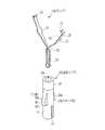
図1に示すように、操作部14は、ワイヤ操作ハンドル62と、シース操作ハンドル63とを有している。ワイヤ操作ハンドル62は、略円筒状であり、その先端にはワイヤ操作ハンドル62よりも小径の円筒状のパイプ64が配されている。ワイヤ操作ハンドル62の上部には、指が挿入可能な貫通窓65が設けられている。貫通窓65内には、指によって、ワイヤ操作ハンドル62の後端側に牽引操作が可能な操作レバー66の一部が露呈されている。操作レバー66には、シース操作ハンドル63及びパイプ64内を通ってワイヤ操作ハンドル62内に挿通された操作ワイヤ12の後端が係止されている。 As shown in FIG. 1, the operation unit 14 includes a wire operation handle 62 and a sheath operation handle 63. The wire operation handle 62 has a substantially cylindrical shape, and a
操作レバー66は、貫通窓65内に露呈される初期位置と、操作ワイヤ12の牽引方向にスライドされるスライド位置との間でスライドが可能なように、ワイヤ操作ハンドル62内に支持されている。操作レバー66のスライド量は、シース11の先端から押し出されたクリップ19を締め付ける際に、操作ワイヤ12がシース11内で牽引される量に相当している。また、操作レバー66は、図示しないバネによって、初期位置に向けて付勢されているので、操作レバー66の牽引操作を解除すると、操作ワイヤ12はバネの付勢によってシース11内で前進される。 The
シース操作ハンドル63は、後端が開放された略円筒状であり、その先端には、シース11の後端が固定されている。シース操作ハンドル63をワイヤ操作ハンドル62に向けて後退させると、シース11が操作ワイヤ12に対して牽引される。シース操作ハンドル63は、シースの牽引方向でスライド自在となるようにパイプ64の外側に装着されている。 The sheath operation handle 63 has a substantially cylindrical shape with an open rear end, and the rear end of the
シース操作ハンドル63内には、パイプ64の上部に設けられたノッチ69に係合して、シース操作ハンドル63を所定のスライド位置でロックするロック機構が設けられている。シース操作ハンドル63の上部には、ロック機構によるスライドロックを解除するロック解除ボタン70が設けられている。ノッチ69の間隔は、シース11内から1つの止血クリップ体17を押し出す際に、シース11が牽引操作される操作量に相当している。ノッチ69は、シース11に装填可能な止血クリップ体17の数に応じて複数個設けられている。 In the sheath operation handle 63, a lock mechanism that engages with a
次に、連発式のクリップ処置具10の作用について説明する。連結クリップユニット13は、複数個の止血クリップ体17と、1つの連結用クリップ体18とを予め連結させた状態で、専用のケースに収容して提供される。詳しくは図示しないが、ケースは、例えば連結リング20の外径よりもわずかに大きな内径を有する円柱状の空間であるクリップ収容部と、このクリップ収容部内に設けられ、連結クリップユニット13の各スカート部38を開いたまま収容する開口または凹部とを備えている。連結クリップユニット13は、各連結リング20がクリップ収容部と開口または凹部により位置決めされるので、各クリップ19と各連結リング20との位置がずれることはなく、スカート部38が閉じた状態で塑性変形することもない。 Next, the operation of the continuous
図7に示すように、連結クリップユニット13を収容したケース75には、各スカート部38を外側から押圧して閉じさせるスカート閉じ通路76と、シース11の先端が挿入されるシース挿入穴77とが設けられている。スカート閉じ通路76は、シース11と同じ内径を有しているので、スカート閉じ通路76と、シース挿入穴77に挿入されたシースとは、その内径面が連接する。クリップ収容部内の連結クリップユニット13は、例えば連結用クリップ体18に操作ワイヤ12を連結して矢印X方向に牽引することにより、クリップ収容部からスカート閉じ通路76を経て、シース11内に引き込まれる。 As shown in FIG. 7, the
クリップ収容部からスカート閉じ通路76内に送り込まれた連結クリップユニット13は、凸部38a,38aがスカート閉じ通路76に押圧されて、スカート部38,38が、連結リング20内に入り込むようにして閉じる。その際に、スカート部38,38の後端側のエッジ38b,38bは、保持部31の外周面よりも内側に押しこまれるので、エッジ38b,38bがシース11の先端に引っ掛かるのを防止することができる。 The connecting
各連結リング20は、凸部38a,38aがスカート閉じ通路76及びシース11の内径面に当接するので、摩擦が小さくなる。そのため、連結クリップユニット13をスムーズにシース11内に引き込むことができる。また、凸部38a,38aがスカート閉じ通路76及びシース11の内径面に当接することにより、各スカート部38,38によるクリップ19の挟持力も向上するので、クリップ19と連結リング20との間に位置ずれが生じない。 In each connecting
図8(A)に示すように、ケースからシース11内に装填された連結クリップユニット13は、先頭のクリップ19Aの先端がシース11の先端にほぼ一致しており、爪部23,23がシース11の内壁によって閉じ状態に保持されている。 As shown in FIG. 8A, the connecting
シース11は、生体内に挿入された内視鏡の鉗子チャンネルに挿入される。シース11の先端は、内視鏡先端の鉗子出口から突出して、患部に近付けられる。この状態で、1番目のノッチ69から2番目のノッチ69へ移動するように、シース操作ハンドル63が引かれる。この操作により、操作ワイヤ12は移動せず、シース11のみが操作部側に引かれる。 The
図8(B)に示すように、シース11がノッチ69の1間隔分だけ引かれると、シース11の先端が、先頭の連結リング20Aのスカート部38,38が開く位置まで下がる。シース11から突出したクリップ19Aの爪部23,23は、弾性により開放状態に変位する。これにより、1発目のクリップ19Aが使用可能な状態となる。 As shown in FIG. 8B, when the
シース11を引くとき、シース11とシース11に嵌入されている連結リング20A〜20Cとの間に摩擦力が働くが、凸部38a,38aにより摩擦力が小さくなっているので、シース11をスムーズに牽引することができる。また、凸部38a,38aがシース11の内径面に当接することにより、スカート部38,38による各クリップ19の挟持力が向上しているので、シース11と連結リング20との摩擦力によって、クリップ19と連結リング20との間に位置ずれは生じない。 When the
次に、クリップ処置具10を移動させて、開放状態にあるクリップ19Aの爪部23,23を患部に押し付ける。そして、ワイヤ操作ハンドル62の操作レバー66を引くことにより、操作ワイヤ12を所定量引っ張る。操作ワイヤ12を引くことで、連結用クリップ体18から順に係合している全クリップ19A〜19Cが、一様に引っ張られる。 Next, the
図8(B)及び(C)の状態では、シース11の先端に出た連結リング20Aは、スカート部38,38が開いているので、スカート部38,38によるクリップ19Aの押圧保持が解除されている。また、連結リング20Aは、スカート部38,38によりシース11内への後退が阻止されている。そのため、図8(C)に示すように、先頭のクリップ19Aは、操作ワイヤ12が引かれることにより、連結リング20Aに対して後退する。締付部30がクリップ19Aの凸部27の直下まで押し込まれることにより、連結リング20Aによるクリップ19Aの締め付けが完了する。 In the state of FIGS. 8B and 8C, since the
クリップ19Aの締め付け完了と同時に、クリップ19Aと次のクリップ19Bの係合部が連結リング20Aの後端から抜け出る。クリップ19Bの腕部25,25は、自身の弾性力によってシース11の内壁に当たるまで拡開し、爪部23,23の間がクリップ19Aのターン部26の幅よりも広く開いて、クリップ19Aとクリップ19Bとの連結が解除される。図87(D)に示すように、クリップ処置具10全体を移動させて、シース11の先端を患部から離すと、止血クリップ体17Aがシース11の先端から抜け出る。 Simultaneously with the completion of the fastening of the
操作レバー66の牽引操作をやめると、操作レバー66はバネの付勢力によって初期位置に復帰する。これにともない、操作ワイヤ12がシース11内で先端側に移動し、連結用クリップ体18と、クリップ19B,19Cとが押されて、2発目のクリップ19Bの先端は、図8(D)に示すように、シース11の先端にほぼ一致する位置に戻る。以降、一発目の止血クリップ体17Aと同様に、操作部14を操作して、2発目、3発目の止血クリップ体17B,17Cでクリップ処置を行うことができる。 When the pulling operation of the
上記各実施形態では、連結リング20を連発式クリップ処置具10に用いたが、単発式のクリップ処置具にも用いることができる。この場合、後方のクリップとの連結を維持する必要がないので、連結リング20から第2領域35を省略するのが好ましい。また、連結リング20をクリップ19の外側に装着せず、クリップ19の後方に配置してもよい。 In each said embodiment, although the
以上、本発明に係る筒状部材、及び連発式クリップ処置具について詳細に説明したが、本発明は上記の実施例に限定されず、本発明の主旨を逸脱しない範囲において、種々の改良や変更をしてもよいのはもちろんである。また、本発明の筒状部材、及び連発式クリップ処置具は、軟性鏡のほか、硬性鏡にも用いることができる。 As described above, the tubular member and the continuous clip treatment tool according to the present invention have been described in detail. However, the present invention is not limited to the above-described embodiments, and various improvements and modifications can be made without departing from the gist of the present invention. Of course, you may do it. Further, the cylindrical member and the continuous clip treatment tool of the present invention can be used for a rigid endoscope as well as a flexible endoscope.
10 クリップ処置具
11 シース
12 操作ワイヤ
13 連結クリップユニット
14 操作部
17 止血クリップ体
18 連結用クリップ体
19 クリップ
20 連結リング
23 爪部
38 スカート部
38a 凸部
65 ケースDESCRIPTION OF
Claims (6)
Translated fromJapanese前記シース内では内側に閉じ、前記シースの先端通過後に前記シースの内径よりも広幅に開いて前記シース内への後退を阻止するスカート部と、
前記スカート部に形成され、前記スカート部が閉じたときに前記シースの内径面と当接する凸部と、
前記スカート部が前記シースの先端を通過して開いたときに、後端側から挿入された前記クリップの先端側を締め付けて、前記爪部を閉じる締付穴とを備えたことを特徴とする筒状部材。A cylindrical member that is loaded into the sheath of the treatment instrument together with a clip having a freely openable / closable claw at the tip,
A skirt that closes inward within the sheath, opens wider than the inner diameter of the sheath after passing through the distal end of the sheath, and prevents retreat into the sheath;
A convex portion that is formed on the skirt portion and abuts against the inner diameter surface of the sheath when the skirt portion is closed;
When the skirt portion is opened through the distal end of the sheath, a fastening hole is provided that tightens the distal end side of the clip inserted from the rear end side and closes the claw portion. A cylindrical member.
1列に並べて連結した複数のクリップと、
前記各クリップとともに前記シース内に装填される請求項1〜5いずれか記載の複数の前記筒状部材と、
前記シース内で最後尾の前記クリップに連結し、複数の前記クリップを牽引する操作ワイヤとを備えたことを特徴とする連発式クリップ処置具。A tubular sheath;
A plurality of clips connected in a row,
A plurality of the cylindrical members according to any one of claims 1 to 5, which are loaded into the sheath together with the clips.
A repetitive clip treatment instrument comprising an operation wire connected to the last clip in the sheath and pulling the plurality of clips.
Priority Applications (2)
| Application Number | Priority Date | Filing Date | Title |
|---|---|---|---|
| JP2008164687AJP2010004941A (en) | 2008-06-24 | 2008-06-24 | Cylindrical member and multiple clip application apparatus |
| US12/489,898US20090318937A1 (en) | 2008-06-24 | 2009-06-23 | Clip coupling method and multiple clip package |
Applications Claiming Priority (1)
| Application Number | Priority Date | Filing Date | Title |
|---|---|---|---|
| JP2008164687AJP2010004941A (en) | 2008-06-24 | 2008-06-24 | Cylindrical member and multiple clip application apparatus |
Publications (1)
| Publication Number | Publication Date |
|---|---|
| JP2010004941Atrue JP2010004941A (en) | 2010-01-14 |
Family
ID=41586120
Family Applications (1)
| Application Number | Title | Priority Date | Filing Date |
|---|---|---|---|
| JP2008164687ACeasedJP2010004941A (en) | 2008-06-24 | 2008-06-24 | Cylindrical member and multiple clip application apparatus |
Country Status (1)
| Country | Link |
|---|---|
| JP (1) | JP2010004941A (en) |
Citations (3)
| Publication number | Priority date | Publication date | Assignee | Title |
|---|---|---|---|---|
| JP2002272751A (en)* | 2001-03-14 | 2002-09-24 | Olympus Optical Co Ltd | Biological tissue clip device |
| JP2006087537A (en)* | 2004-09-22 | 2006-04-06 | Pentax Corp | Endoscopic clip device |
| JP2008036003A (en)* | 2006-08-03 | 2008-02-21 | Olympus Medical Systems Corp | Endoscopic treatment tool |
- 2008
- 2008-06-24JPJP2008164687Apatent/JP2010004941A/ennot_activeCeased
Patent Citations (3)
| Publication number | Priority date | Publication date | Assignee | Title |
|---|---|---|---|---|
| JP2002272751A (en)* | 2001-03-14 | 2002-09-24 | Olympus Optical Co Ltd | Biological tissue clip device |
| JP2006087537A (en)* | 2004-09-22 | 2006-04-06 | Pentax Corp | Endoscopic clip device |
| JP2008036003A (en)* | 2006-08-03 | 2008-02-21 | Olympus Medical Systems Corp | Endoscopic treatment tool |
Similar Documents
| Publication | Publication Date | Title |
|---|---|---|
| EP2098175B1 (en) | Clipping device | |
| JP5006753B2 (en) | Endoscopic clip device | |
| JP4598181B2 (en) | Endoscopic clip device | |
| US20090223028A1 (en) | Magazine type clipping device | |
| EP2335610A2 (en) | Magazine type clipping device | |
| JP5064334B2 (en) | Clip package and clip loading method | |
| JP2009268637A (en) | Dummy clip, multiple clip package, and clip filling method | |
| JP2007283015A (en) | Endoscopic clip device | |
| JP2010136820A (en) | Cylindrical member and repeating type clip treatment instrument | |
| JP4491589B2 (en) | Endoscopic clip device | |
| JP2010004941A (en) | Cylindrical member and multiple clip application apparatus | |
| JP2009261772A (en) | Coupling ring, coupling clip package, and clip loading method | |
| JP2010136818A (en) | Repeating type clip treatment instrument | |
| JP2010119682A (en) | Cylindrical member, and multiple clip application device | |
| JP4782807B2 (en) | Repetitive clip treatment tool | |
| JP2010012168A (en) | Successive clipping device | |
| JP2010035808A (en) | Connection clip package | |
| JP2010035820A (en) | Clipping tool | |
| JP2010063702A (en) | Multiple clip unit | |
| JP4838278B2 (en) | Linked clip package and clip loading method | |
| JP4782806B2 (en) | Linked clip package and clip loading method | |
| JP2010213990A (en) | Connection clip package, and clip loading method | |
| JP4782808B2 (en) | Repetitive clip treatment device and loading method of connecting clip | |
| JP2009233314A (en) | Clipping device | |
| JP2009233309A (en) | Magazine type clipping device |
Legal Events
| Date | Code | Title | Description |
|---|---|---|---|
| A621 | Written request for application examination | Free format text:JAPANESE INTERMEDIATE CODE: A621 Effective date:20110114 | |
| A977 | Report on retrieval | Free format text:JAPANESE INTERMEDIATE CODE: A971007 Effective date:20120924 | |
| A01 | Written decision to grant a patent or to grant a registration (utility model) | Free format text:JAPANESE INTERMEDIATE CODE: A01 Effective date:20121003 | |
| A045 | Written measure of dismissal of application | Free format text:JAPANESE INTERMEDIATE CODE: A045 Effective date:20130227 |