JP2009544383A - Robot system that supports non-invasive surgery that can position surgical instruments according to instructions from the surgeon without attaching to the operating table or pre-calibrating the insertion point - Google Patents
Robot system that supports non-invasive surgery that can position surgical instruments according to instructions from the surgeon without attaching to the operating table or pre-calibrating the insertion pointDownload PDFInfo
- Publication number
- JP2009544383A JP2009544383AJP2009521282AJP2009521282AJP2009544383AJP 2009544383 AJP2009544383 AJP 2009544383AJP 2009521282 AJP2009521282 AJP 2009521282AJP 2009521282 AJP2009521282 AJP 2009521282AJP 2009544383 AJP2009544383 AJP 2009544383A
- Authority
- JP
- Japan
- Prior art keywords
- robot
- joint
- insertion point
- controller
- calibration
- Prior art date
- Legal status (The legal status is an assumption and is not a legal conclusion. Google has not performed a legal analysis and makes no representation as to the accuracy of the status listed.)
- Pending
Links
- 238000003780insertionMethods0.000titleclaimsabstractdescription54
- 230000037431insertionEffects0.000titleclaimsabstractdescription54
- 238000001356surgical procedureMethods0.000titleclaimsdescription34
- 230000033001locomotionEffects0.000claimsabstractdescription45
- 238000000034methodMethods0.000claimsabstractdescription39
- 238000002324minimally invasive surgeryMethods0.000claimsabstractdescription9
- 230000004044responseEffects0.000claimsabstractdescription5
- 230000008878couplingEffects0.000claimsdescription17
- 238000010168coupling processMethods0.000claimsdescription17
- 238000005859coupling reactionMethods0.000claimsdescription17
- 230000005540biological transmissionEffects0.000claimsdescription11
- 238000002357laparoscopic surgeryMethods0.000claimsdescription6
- 238000012806monitoring deviceMethods0.000claimsdescription6
- 230000003044adaptive effectEffects0.000claimsdescription5
- 238000004891communicationMethods0.000claimsdescription5
- 239000000463materialSubstances0.000claimsdescription4
- 230000007246mechanismEffects0.000claimsdescription3
- 238000006243chemical reactionMethods0.000claimsdescription2
- 238000012937correctionMethods0.000claimsdescription2
- 230000007257malfunctionEffects0.000claimsdescription2
- 238000012544monitoring processMethods0.000claimsdescription2
- 238000002360preparation methodMethods0.000claimsdescription2
- 210000001015abdomenAnatomy0.000description8
- 238000010586diagramMethods0.000description7
- 230000006870functionEffects0.000description6
- 206010002091AnaesthesiaDiseases0.000description4
- 230000037005anaesthesiaEffects0.000description4
- 230000000694effectsEffects0.000description4
- 230000003287optical effectEffects0.000description4
- 230000008859changeEffects0.000description3
- 230000004048modificationEffects0.000description3
- 238000012986modificationMethods0.000description3
- 230000003068static effectEffects0.000description3
- 230000008901benefitEffects0.000description2
- 238000013461designMethods0.000description2
- 230000008569processEffects0.000description2
- 230000009467reductionEffects0.000description2
- 238000005070samplingMethods0.000description2
- 210000001519tissueAnatomy0.000description2
- 230000007704transitionEffects0.000description2
- 210000000707wristAnatomy0.000description2
- 206010019909HerniaDiseases0.000description1
- 208000034693LacerationDiseases0.000description1
- 230000001133accelerationEffects0.000description1
- 230000006978adaptationEffects0.000description1
- 230000003321amplificationEffects0.000description1
- 238000004140cleaningMethods0.000description1
- 238000011161developmentMethods0.000description1
- 201000010099diseaseDiseases0.000description1
- 208000037265diseases, disorders, signs and symptomsDiseases0.000description1
- 238000006073displacement reactionMethods0.000description1
- 238000001839endoscopyMethods0.000description1
- 210000000232gallbladderAnatomy0.000description1
- 239000012212insulatorSubstances0.000description1
- 238000002350laparotomyMethods0.000description1
- 238000005259measurementMethods0.000description1
- 238000003199nucleic acid amplification methodMethods0.000description1
- 238000002355open surgical procedureMethods0.000description1
- 230000002980postoperative effectEffects0.000description1
- 210000002307prostateAnatomy0.000description1
- 230000008439repair processEffects0.000description1
- 238000002271resectionMethods0.000description1
- 230000033764rhythmic processEffects0.000description1
- 230000035807sensationEffects0.000description1
- 238000012549trainingMethods0.000description1
- 238000012546transferMethods0.000description1
- 210000001835visceraAnatomy0.000description1
- 230000000007visual effectEffects0.000description1
- 230000001755vocal effectEffects0.000description1
Images


Classifications
- A—HUMAN NECESSITIES
- A61—MEDICAL OR VETERINARY SCIENCE; HYGIENE
- A61B—DIAGNOSIS; SURGERY; IDENTIFICATION
- A61B90/00—Instruments, implements or accessories specially adapted for surgery or diagnosis and not covered by any of the groups A61B1/00 - A61B50/00, e.g. for luxation treatment or for protecting wound edges
- A—HUMAN NECESSITIES
- A61—MEDICAL OR VETERINARY SCIENCE; HYGIENE
- A61B—DIAGNOSIS; SURGERY; IDENTIFICATION
- A61B34/00—Computer-aided surgery; Manipulators or robots specially adapted for use in surgery
- A61B34/30—Surgical robots
- A—HUMAN NECESSITIES
- A61—MEDICAL OR VETERINARY SCIENCE; HYGIENE
- A61B—DIAGNOSIS; SURGERY; IDENTIFICATION
- A61B17/00—Surgical instruments, devices or methods
- A—HUMAN NECESSITIES
- A61—MEDICAL OR VETERINARY SCIENCE; HYGIENE
- A61B—DIAGNOSIS; SURGERY; IDENTIFICATION
- A61B17/00—Surgical instruments, devices or methods
- A61B17/00234—Surgical instruments, devices or methods for minimally invasive surgery
- A—HUMAN NECESSITIES
- A61—MEDICAL OR VETERINARY SCIENCE; HYGIENE
- A61B—DIAGNOSIS; SURGERY; IDENTIFICATION
- A61B17/00—Surgical instruments, devices or methods
- A61B2017/00017—Electrical control of surgical instruments
- A61B2017/00115—Electrical control of surgical instruments with audible or visual output
- A—HUMAN NECESSITIES
- A61—MEDICAL OR VETERINARY SCIENCE; HYGIENE
- A61B—DIAGNOSIS; SURGERY; IDENTIFICATION
- A61B17/00—Surgical instruments, devices or methods
- A61B2017/00017—Electrical control of surgical instruments
- A61B2017/00203—Electrical control of surgical instruments with speech control or speech recognition
- A—HUMAN NECESSITIES
- A61—MEDICAL OR VETERINARY SCIENCE; HYGIENE
- A61B—DIAGNOSIS; SURGERY; IDENTIFICATION
- A61B17/00—Surgical instruments, devices or methods
- A61B2017/00681—Aspects not otherwise provided for
- A61B2017/00734—Aspects not otherwise provided for battery operated
- A—HUMAN NECESSITIES
- A61—MEDICAL OR VETERINARY SCIENCE; HYGIENE
- A61B—DIAGNOSIS; SURGERY; IDENTIFICATION
- A61B34/00—Computer-aided surgery; Manipulators or robots specially adapted for use in surgery
- A61B34/30—Surgical robots
- A61B2034/305—Details of wrist mechanisms at distal ends of robotic arms
- A—HUMAN NECESSITIES
- A61—MEDICAL OR VETERINARY SCIENCE; HYGIENE
- A61B—DIAGNOSIS; SURGERY; IDENTIFICATION
- A61B34/00—Computer-aided surgery; Manipulators or robots specially adapted for use in surgery
- A61B34/70—Manipulators specially adapted for use in surgery
- A61B34/74—Manipulators with manual electric input means
- A61B2034/742—Joysticks
- A—HUMAN NECESSITIES
- A61—MEDICAL OR VETERINARY SCIENCE; HYGIENE
- A61B—DIAGNOSIS; SURGERY; IDENTIFICATION
- A61B90/00—Instruments, implements or accessories specially adapted for surgery or diagnosis and not covered by any of the groups A61B1/00 - A61B50/00, e.g. for luxation treatment or for protecting wound edges
- A61B90/36—Image-producing devices or illumination devices not otherwise provided for
- A61B90/361—Image-producing devices, e.g. surgical cameras
- A—HUMAN NECESSITIES
- A61—MEDICAL OR VETERINARY SCIENCE; HYGIENE
- A61B—DIAGNOSIS; SURGERY; IDENTIFICATION
- A61B90/00—Instruments, implements or accessories specially adapted for surgery or diagnosis and not covered by any of the groups A61B1/00 - A61B50/00, e.g. for luxation treatment or for protecting wound edges
- A61B90/36—Image-producing devices or illumination devices not otherwise provided for
- A61B90/37—Surgical systems with images on a monitor during operation
Landscapes
- Health & Medical Sciences (AREA)
- Surgery (AREA)
- Life Sciences & Earth Sciences (AREA)
- Engineering & Computer Science (AREA)
- Molecular Biology (AREA)
- Biomedical Technology (AREA)
- Heart & Thoracic Surgery (AREA)
- Medical Informatics (AREA)
- Nuclear Medicine, Radiotherapy & Molecular Imaging (AREA)
- Animal Behavior & Ethology (AREA)
- General Health & Medical Sciences (AREA)
- Public Health (AREA)
- Veterinary Medicine (AREA)
- Robotics (AREA)
- Oral & Maxillofacial Surgery (AREA)
- Pathology (AREA)
- Manipulator (AREA)
Abstract
Translated fromJapaneseDescription
Translated fromJapanese本発明は、外科手術とロボット工学の分野、特に外科手術向け支援システムの分野に係り、より正確には特に手術器具として設計された操作ロボットに関する。 The present invention relates to the field of surgery and robotics, in particular to the field of surgical support systems, and more precisely to an operating robot specifically designed as a surgical instrument.
腹腔鏡検査技術を用いる外科手術は、患者の腹部の小さな切開箇所を介する施術からなる。具体的手術に必要な器具は、施術箇所の領域を外科医が視認できるようにするカメラの光学系と同様これらの切開箇所から挿入される。必要な切開の大きさはこの技術により劇的に低減でき、そのことが審美的により小さな影響だけでなく患者に対するより少ない危険やより短い術後期間やより低コストの手術もまたもたらす。 Surgery using laparoscopic techniques consists of a procedure through a small incision in the patient's abdomen. Instruments required for specific surgery are inserted through these incisions as well as camera optics that allow the surgeon to see the area of the procedure. The required incision size can be dramatically reduced by this technique, which not only results in less aesthetic impact, but also results in less risk to the patient, shorter post-operative periods and lower cost surgery.
今日、これらの手術における通常の措置は、外科医が患者の腹部に挿入された手術器具群を用いつつ助手の助けを借りてのカメラの保持からなる。これは、助手と外科医との間の大きな協応を必要とし、これが首尾よく行えるようにするには三つの基本的な課題を有する。
1)外科医は、自らが助手にして欲しいことが何であるかを刻々と明確に伝達しなければならない。このことは口頭伝達のあらゆる課題にさらされ、必ずしも外科医が期待する結果が達成されるとは限らない。外科医と自らの助手との間の理解が深まるほど、外科医が自らの欲する内容を明確に説明しなかったり或いは助手が外科医の指示を誤解するときが存在する。
2)画像は、カメラを人が支えているため、全体的に安定しておらず、かくしてそれを扱う助手の律動による影響を受ける。この影響は、手術時間が延びるにつれ増大する。
3)助手は、居心地の悪い位置にいるため、特に疲労により影響を受けているときにカメラを精度よく動かすのに難渋する。これにより、一部内臓をカメラ光学系が時に擦過し、そのことでひいてはその除去と清掃が必要となる。この課題は手術時間と、かくして患者が麻酔下にある時間を引き延ばし、そのことが麻酔に固有の危険を増大させる。Today, the usual procedure in these surgeries consists of holding the camera with the help of an assistant while the surgeon uses a group of surgical instruments inserted into the patient's abdomen. This requires a great deal of cooperation between the assistant and the surgeon and has three basic challenges in order to be able to do this successfully.
1) The surgeon must clearly communicate what he wants to be his assistant. This exposes all the challenges of oral transmission and does not necessarily achieve the results expected by surgeons. The deeper the understanding between the surgeon and his assistant, the more the surgeon does not clearly explain what he wants or the assistant may misunderstand the surgeon's instructions.
2) The image is not entirely stable because the camera is supported by a person, and is thus influenced by the rhythm of the assistant who handles it. This effect increases as the operation time increases.
3) Since the assistant is in an uncomfortable position, it is difficult to move the camera accurately, particularly when the assistant is affected by fatigue. As a result, some internal organs are sometimes scraped by the camera optical system, which in turn necessitates removal and cleaning. This task prolongs the operation time and thus the time that the patient is under anesthesia, which increases the risks inherent in anesthesia.
さらに、外科医が同時に3個以上の器具を使用する必要のあるときが何回かあり、そのことが副外科医の手術への参加を要求する。これが、前述の第1項の協応課題をさらに悪化させる。 In addition, there are several times when a surgeon needs to use more than two instruments at the same time, which requires the attendance of a secondary surgeon. This further aggravates the cooperation problem of the first item.
さらに、腹部への外科器具の挿入点は側方に変更はできず、そのことが挿入点周りの二方向の回動と器具の軸周りの一方向の回動と該軸に沿う移動に対する前記器具の可動性を制限する。これらの動きの特性が、取り扱いに一連の問題を課す。
1)動きの反転。挿入点は支点として機能し、器具をその周りに揺動させる(挿入−引き抜きの動作を除く)。かくして、外科医の手の右方への動きは器具の端部の左方への動きを生ずる。
2)規模。まるでレバーの如く、術具は挿入に応じて外科医の動きを増幅或いは縮減する。特定値を上回る挿入については増幅が存在し、その値未満では縮減が存在する。この効果が動きに対しそれ自体を制限するだけでなく作用力もまた含むことは、指摘に値することである。
3)タッチ感覚の喪失。切開手術措置において外科医に極めて役立つ組織の手触りや労力は、組織との直接的接触が失われるが故に内視鏡検査技術では極めて限定された仕方で伝達される。その上、套管針に対する梃子及び摩擦の影響は外科医がアクセスするこの種僅かな情報を歪めたり遮ったりする。In addition, the insertion point of the surgical instrument into the abdomen cannot be changed laterally, which is the result of the two-way rotation around the insertion point, the one-way rotation around the instrument axis and the movement along the axis. Limit the mobility of the instrument. These movement characteristics impose a series of problems on handling.
1) Reversal of movement. The insertion point functions as a fulcrum and swings the instrument about it (except for the insertion-retraction operation). Thus, the rightward movement of the surgeon's hand results in a leftward movement of the instrument end.
2) Scale. Like a lever, the surgical tool amplifies or reduces the surgeon's movement upon insertion. There is amplification for insertions above a certain value, and there is a reduction below that value. It is worth pointing out that this effect not only limits itself to movement, but also includes acting force.
3) Loss of touch sensation. The tissue feel and effort that is extremely helpful to the surgeon in the open surgical procedure is transmitted in a very limited manner in endoscopy techniques due to the loss of direct contact with the tissue. Moreover, the influence of insulators and friction on the trocar can distort or block this small amount of information accessed by the surgeon.
視覚的課題(視野の低減や画像深度の喪失や照明変化等)同様、最小侵襲性手術における手際が課す課題は集中訓練を通じて大幅に克服することができる。しかしながら、同様にこれがしかるべき外科医にこれらの技法の組み込みを促す。 Similar to visual challenges (such as reduced field of view, loss of image depth, and changes in lighting), the challenges of minimally invasive surgery can be greatly overcome through intensive training. However, this also encourages the appropriate surgeon to incorporate these techniques.
これらの不便さに対する少なくとも部分的解決策として、その後に腹腔鏡検査カメラの取り扱い等の彼又は彼女の仕事の一部において外科医を支援すべく、腹腔鏡検査手術用の異なるロボット化支援システムが提案(例えば、特許文献1や特許文献2)されている。これらのシステムは、下記戦略の一つに従って設計されている。
1)その運動学的力が被保持手術器具を患者の腹部内の器具の挿入点に一致させる遠端回転中心周りに動かすよう強制するような特性の機械構造。これは、手術開始時ロボット化システムの関与前に較正措置を用いて達成される(例えば、特許文献2)。
2)受動的継手に基づく端部アクチュエータで、かくしてこの端部アクチュエータと患者の腹部内の術具の挿入点が意味する支持点とを位置決めすることで、前記器具は固定されたままとなり、理想的には所望の如く位置決めされ配向される。受動的継手の存在が、器具に対し指示された動きにも拘わらず、たとえ前記点の位置の不正確な知識にも拘わらず、側方力が挿入点に一切作用しないよう保証する。しかしながら、術具の向きは直接制御されず、むしろそれを保持する端部アクチュエータにより空間内でとる位置によってのみ制御されるため、それを外科医が望む如く正確に配置できるようにすべく術具の挿入点の場所を知る必要がある。前記位置は幾何学的方法を用い、ロボットを手術台に物理的に固定して推定誤差を制限し、手術中のロボットと挿入点との相対的位置における変化を防止することで計算される(例えば、特許文献1)。As at least a partial solution to these inconveniences, a different robotization support system for laparoscopic surgery has been proposed to subsequently assist the surgeon in some of his or her work, such as handling laparoscopic cameras (For example, Patent Document 1 and Patent Document 2). These systems are designed according to one of the following strategies.
1) A mechanical structure whose characteristics are such that its kinematic force forces the surgical instrument to be held to move about a far-end rotation center that matches the insertion point of the instrument in the patient's abdomen. This is accomplished using a calibration measure prior to involvement of the robotization system at the start of surgery (eg, US Pat.
2) An end actuator based on a passive coupling, thus positioning the end actuator and the support point implied by the insertion point of the surgical instrument in the patient's abdomen, leaving the instrument fixed and ideal Specifically, it is positioned and oriented as desired. The presence of the passive coupling ensures that no lateral force acts on the insertion point, despite the movements directed to the instrument, even though inaccurate knowledge of the position of the point. However, the orientation of the surgical tool is not directly controlled, but rather is controlled only by the position it takes in space by the end actuator that holds it, so that the surgical tool can be placed exactly as desired by the surgeon. You need to know the location of the insertion point. The position is calculated using a geometric method by physically fixing the robot to the operating table to limit the estimation error and preventing changes in the relative position between the robot and the insertion point during surgery ( For example, Patent Document 1).
外科診療を改善する目的をもって先の戦略の一つに従って設計された外科手術用の先行する幾つかのロボットシステムが存在する。例えば、特許文献3は、腹腔鏡検査手術に貢献するよう改変された工業ロボットの操作を提示している。ロボットの改変は、それを手術室内に都合よく配置できるようにする車輪と人−機械インタフェースとして機能するコンピュータと合わせ二つの受動的継手を用いる端部アクチュエータとを有する可動組立体に存する。加えて、それは初期較正を通じて揺動点(保持された腹腔鏡検査具の挿入点)の計算手順を有する。しかしながら、組立体の容積と複雑さとが本システムの適用を制限する。 There are several previous robotic systems for surgery designed according to one of the previous strategies with the aim of improving surgical practice. For example, Patent Document 3 presents the operation of an industrial robot that has been modified to contribute to laparoscopic surgery. A modification of the robot resides in a movable assembly having wheels that allow it to be conveniently placed in the operating room, a computer that functions as a man-machine interface, and an end actuator that uses two passive couplings. In addition, it has a procedure for calculating the rocking point (the insertion point of the held laparoscopic instrument) through initial calibration. However, the volume and complexity of the assembly limits the application of the system.
特許文献4は、遠端回転中心に基づくロボット外科手術システムを提示している。この種のものは、ロボット機構の遠端回転中心に術具の挿入点を一致させることを保証するための慎重な初期較正を必要とする不便さを有する。この不便さは、例えば手術が2以上の疾患(頻発する症例を挙げるに、鼠蹊部ヘルニアや胆嚢切除)向けであるときに被保持術具の挿入点を変更する必要がある場合の手術におけるロボットの使用を大幅に妨げるものである。 Patent Document 4 presents a robotic surgical system based on the far-end rotation center. This type has the inconvenience of requiring careful initial calibration to ensure that the insertion point of the surgical tool is aligned with the far end rotation center of the robotic mechanism. This inconvenience is caused by, for example, a robot in a surgical operation when it is necessary to change the insertion point of a held surgical tool when the operation is for two or more diseases (for example, a case where the hernia or gallbladder is removed). The use of is greatly hindered.
特許文献5では、特許の目的は引っ張りロープを用いた動きの伝達と計7自由度(たった3個のアクチュエータでもって)とに基づく具体的設計を有する外科手術ロボットにある。それは、基本的な遠隔外科システムを必然的に伴うインターネット(Internet)上で指示を受け取る可能性もまた含むものである。さらに、それは手術中にロボットがとる位置を見当合わせする可能性を提供している。これら全てにも拘わらず、かつケーブルを介する動き伝送システムの複雑さに加え、それは依然として特許文献3に示されたものと全く同様の揺動点の初期較正手順を必要とするのである。 In Patent Document 5, the patent is for a surgical robot having a specific design based on motion transmission using a pull rope and a total of 7 degrees of freedom (with only 3 actuators). It also includes the possibility of receiving instructions on the Internet, which entails a basic telesurgical system. In addition, it offers the possibility of registering the position taken by the robot during surgery. In spite of all of this and in addition to the complexity of the motion transmission system via cable, it still requires an initial calibration procedure of the swing point exactly as shown in US Pat.
特許文献6には、受動的継手に基づく外科手術用のロボットシステムが記載されており、それは4個の能動的継手(及びかくして4個のエンジン)を有している。それは、二つの重要な制約を有しており、ロボットを手術台に繋ぎ止めておかねばならず、術具の挿入点の位置を割り出すべく手術前に初期較正措置を遂行しなければならない。同じ制約が特許文献7に見出すことができ、そこには特許文献6に提示された操作ロボットに基づく遠隔外科手術システムが提示されている。 In US Pat. No. 6,057,836, a surgical robot system based on passive joints is described, which has four active joints (and thus four engines). It has two important constraints, the robot must be secured to the operating table, and an initial calibration procedure must be performed prior to surgery to determine the location of the surgical instrument insertion point. The same constraint can be found in US Pat. No. 6,057,089, which presents a telesurgical system based on the operating robot presented in US Pat.
特許文献8には双系外科手術システムが記述されており、そこではロボットに装着した術具と人的オペレータが取り扱うジョイスティックとの間に直接的な対応が確立されている。このシステムは顕微鏡検査手術に用いられ、ここでは遠隔外科手術は患者から離れた場所の外科医の介入を可能にする手段としてではなく、手術室に居る外科医の技量を増す手段として用いられる。その遠隔外科手術のアーキテクチャはこの可能性を熟慮するものではなく、システムの異なる要素間の実時間通信に大幅に依存するものであり、このことは前述の遠隔外科手術の場合には非現実的となる筈である。 Patent Document 8 describes a twin-system surgical system, in which a direct correspondence is established between a surgical tool attached to a robot and a joystick handled by a human operator. This system is used for microscopic surgery, where telesurgery is not used as a means to allow the intervention of a surgeon away from the patient, but as a means to increase the skill of the surgeon in the operating room. Its telesurgical architecture does not take this possibility into account, but relies heavily on real-time communication between the different elements of the system, which is impractical in the case of the aforementioned remote surgery. It is a trap.
特許文献9には特許文献8と同様の手法を用いるテレプレゼンスからなる外科手術システムが記述されており、ここでは外科医は侵襲効果を探る過程で手術現場のより多量の情報を受け取る。それは、システムの通信要件が専用ネットワークの使用を必要とし、インターネット等の汎用ネットワークの使用を退ける限り、外科医が遠隔場所に居る場合を部分的にしか熟慮しないものである。 Patent Document 9 describes a surgical system comprising telepresence using a method similar to that of Patent Document 8, in which a surgeon receives a greater amount of information on the surgical site in the process of searching for invasive effects. It only partially considers when the surgeon is at a remote location, as long as the communication requirements of the system require the use of a dedicated network and withdraw from the use of a general purpose network such as the Internet.
特許文献10は、ロボット構成要素が特許文献3と特許文献5のものとは異なる構成を有する特別な設計からなる操作装置(この場合、3個の能動的自由度に2個の受動的自由度を加えたものからなる)であるロボット遠隔外科医手術システムを提示している。操作装置はまた無線特徴(電池やマイクロフォン)を有しており、それは異なる機能と物理的場所とを有するモジュールを介し、かつ手術室内の外科医と遠隔場所の外科医との間の図形情報の交換を伴う遠隔外科手術システム内に組み込まれている。同様のシステムながら、操作型工業ロボットに基づく前立腺の経尿道切除専用であるシステムが、特許文献11に記載されている。 Patent Document 10 describes an operation device having a special design in which the robot components are different from those of Patent Document 3 and Patent Document 5 (in this case, three active degrees of freedom and two passive degrees of freedom). A robot telesurgeon surgery system. The operating device also has wireless features (batteries and microphones), which exchange graphic information between surgeons in the operating room and remote surgeons via modules with different functions and physical locations. Integrated into the associated telesurgical system. A system dedicated to transurethral resection of the prostate based on a maneuverable industrial robot, although similar, is described in US Pat.
要約するに、現行技術水準は幾つかの限界を呈するものである。
1)手術台への支援ロボットの固定は該台の修正を必要とし、そのことがロボット化支援システムとその拡張の効果を制限する。
2)手術台への支援ロボットの固定が、その機能不全の場合或いはその使用が不要である場合(外科措置を腹腔鏡検査から開腹術或いは従来の「切開」手術へ転換する場合等)に、その引き抜きを妨げたり或いは阻むことすらある。
3)システムが挿入点を知る手術前の較正手順の要件(両戦略における)には、外科手術における追加の作業が含まれ、それが手術時間(その間患者は麻酔下にある)を引き延ばしたり、或いは支援ロボットの使用から引き出すことのできる利点を低減することがある。
4)事前較正の必要性は、手術中に初期位置以外の挿入点を介して器具を挿入する必要がある場合(これは患者が同じ手術中に2以上の外科手術を受けるときに普通である)、前記較正を反復して新たな挿入点箇所を見出す必要があり、そのことがさらに手術を引き延ばし、ロボットシステムの融通性を制限する。In summary, the current state of the art presents some limitations.
1) Fixing the support robot to the operating table requires modification of the table, which limits the effectiveness of the robotization support system and its expansion.
2) When the support robot is fixed to the operating table, if it is malfunctioning or it is not necessary to use it (for example, when the surgical procedure is changed from laparoscopic to laparotomy or conventional “incision” surgery), It may even prevent or even prevent the withdrawal.
3) The requirements of the pre-operative calibration procedure where the system knows the insertion point (in both strategies) include additional work in the surgery, which extends the operating time (while the patient is under anesthesia) Or it may reduce the benefits that can be derived from the use of the assistive robot.
4) The need for pre-calibration is common when instruments need to be inserted through an insertion point other than the initial position during surgery (this is common when a patient undergoes two or more surgeries during the same surgery) ), It is necessary to repeat the calibration to find a new insertion point location, which further lengthens the operation and limits the flexibility of the robotic system.
本文献は、自由度の異なるロボットアームの汎用構成と全体的なロボット化システム自体の汎用構成とを介して、システムを手術台に物理的に固定したり患者の腹部内のカメラ挿入点を事前に較正したりすることなく、最小侵襲性外科手術にて腹腔鏡検査カメラを確実に取り扱うことができるロボットシステムと、手術台に対しそれを物理的に固定する必要性或いは外科手術においてシステムを介在させ始める前の較正措置を伴うことなく、所望場所に到達させるのにカメラに対し与えるべき動きを計算する適切な方法とを記述するものである。 This document is based on the general configuration of the robot arm with different degrees of freedom and the general configuration of the entire robotization system itself, and the system is physically fixed to the operating table and the camera insertion point in the patient's abdomen is preliminarily determined. A robot system that can reliably handle laparoscopic cameras in minimally invasive surgery without the need to calibrate and need to physically fix it to the operating table or intervene in surgery It describes a suitable method for calculating the movement to be made to the camera to reach the desired location without any calibration measures before starting to do so.
本システムは、3個の能動的自由度を有する操作ロボットと、腹腔鏡検査手術用のカメラを保持するよう特別に設計された2個の受動的自由度を有する端部アクチュエータと、事前較正や或いは手術台への組立体の固定を必要とすることなくカメラを所望場所へ到達させる上で与えるべき動きを計算する方法を実施することのできるその構造内の一体化ロボット用コントローラと、システムに対し所望の動作を指示するインタフェースシステムとを備えるものである。 The system includes an operating robot with three active degrees of freedom, two end actuators with passive degrees of freedom specifically designed to hold a camera for laparoscopic surgery, pre-calibration and Or a controller for an integrated robot in that structure that can implement a method for calculating the movement to be made to bring the camera to the desired location without requiring the assembly to be secured to the operating table; And an interface system for instructing a desired operation.
端部アクチュエータは、それが二つの受動的自由度をロボットに対し付加するよう設計してある。このことで患者の腹部内の腹腔鏡検査具の動きがより安全になり、何故なら腹腔鏡検査に通常使用される(外科医が直接使用するときの)手術器具の使用は揺動点が患者の皮膚内に挿入された箇所で構成される揺動点周りの動きに依拠するからである。これら二つの受動的継手の使用により揺動点が術具の動きにより当然に確立できるようになり、何故ならそれは人が術具を扱うときに、器具がロボットの手首に直接固定した場合に起き得ることに対して行われるからであり、揺動点の確立はそれを予測する計算によって決まる筈だからである。この場合、どんな誤差もロボットシステム内で揺動点をその実際の場所から患者の皮膚を押す予測場所へ付勢しがちとする結果を招く筈である。この誤差の大きさに応じ、この揺動点の計算における失敗が患者の皮膚の裂傷等の危険な状況を引き起しかねない。対照的に、受動的継手を含むシステムの場合、揺動点の計算時の誤差がシステムの性能を制限し、手術の必要性に従って端部アクチュエータを配置する限り、揺動点或いは挿入点により与えられる追加の支持点に従ってその位置を計算する必要がある。本発明では、スリップすなわち手術台に対するロボットの物理的固定を用いてロボットと患者の相対的位置を固定したり、或いは揺動点の場所の事前の計算を行う代りに、先の代替案の双方を排除する所望位置へカメラを到達させるのに与えるべき動きを計算する方法が存在する。かくして、手術室内へのシステムの組み込みが容易となり(何故なら、それはそれを固定する手術台の改変を必要としないから)、手術の安全性が増す(何故なら、それは必要に応じて簡単かつ迅速に取り除くことができ、手術台での患者位置を変えたり手術中に必要とされるカメラの挿入点を変えたりする場合のシステムの弱点を取り除くからである)。 The end actuator is designed so that it adds two passive degrees of freedom to the robot. This makes the movement of the laparoscopic instrument in the patient's abdomen safer, because the use of surgical instruments usually used for laparoscopy (when used directly by the surgeon) This is because it relies on the movement around the rocking point constituted by the portion inserted into the skin. The use of these two passive joints allows the point of swing to be established naturally by the movement of the instrument, because it occurs when the instrument is fixed directly to the robot wrist when a person handles the instrument. This is because the establishment of the oscillating point should be determined by the calculation that predicts it. In this case, any error should result in the robot system tending to bias the rocking point from its actual location to the predicted location of pushing the patient's skin. Depending on the magnitude of this error, failure in this rocking point calculation can cause dangerous situations such as laceration of the patient's skin. In contrast, for systems that include passive couplings, errors in the calculation of the swing point are limited by the swing point or insertion point, as long as the end actuator is placed according to the surgical needs, limiting system performance. The position needs to be calculated according to the additional support points that are provided. In the present invention, instead of using a slip or physical fixation of the robot to the operating table to fix the relative position of the robot and the patient, or to pre-calculate the location of the swing point, both of the previous alternatives There is a way to calculate the movement to be made to get the camera to the desired position. Thus, the system can be easily integrated into the operating room (because it does not require modification of the operating table to which it is secured) and the safety of the operation is increased (because it is simple and quick as needed). Because it removes the weaknesses of the system when changing the patient position on the operating table or changing the insertion point of the camera needed during surgery).
システム全体が電池を介して給電され、手術中に組立体を移動不能にできるブレーキ付き車輪を有しており、同時に手術中に手術台との間での移送或いは撤去のいずれも行えるよう把手を用いてその動きを促進する。 The entire system is powered by batteries and has braked wheels that can make the assembly immovable during surgery, and at the same time handles to allow either transfer to or removal from the operating table during surgery. Use to promote that movement.
本システムは、3個の能動的自由度を有する(換言すれば、電動化された)ロボットアームと、2個の受動的自由度(エンジンを持たない)が組み込まれ、一般に腹腔鏡検査手術に用いられる種の標準的カメラを固締するよう特別に設計された端部アクチュエータと、その構造内に組み込まれ、事前較正や或いは手術台への組立体固定の必要なくカメラを所望場所へ到達させるのに与える必要のある動きを計算する方法を実行することのできるロボットアーム用コントローラと、外科医の指示を解釈し、ユーザに対しシステム情報を提供するだけでなくそれらを前述のコントローラへ送信することもするインタフェースシステムとを備える。インタフェースシステムは片や、コントローラに付属する内部モジュールと、外科医にロボットを介して自らが望む如く手術器具を動かせるようにする指示を入力する手段とを備える。この内部モジュールは、入力手段を介し表明される外科医の指示に応答してロボットに適した動きの指示を生成する。 The system incorporates a robot arm with three active degrees of freedom (in other words, motorized) and two passive degrees of freedom (without an engine), which are commonly used in laparoscopic surgery. End actuators specially designed to clamp the standard camera of the type used and built into its structure to bring the camera to the desired location without the need for pre-calibration or fixing the assembly to the operating table A controller for a robotic arm that can perform a method of calculating the movements that need to be given, and interpreting the surgeon's instructions and not only providing system information to the user but also sending them to the controller And an interface system. The interface system comprises a strip, an internal module attached to the controller, and means for inputting instructions to the surgeon via the robot to move the surgical instrument as desired. This internal module generates motion instructions suitable for the robot in response to surgeon instructions expressed via the input means.
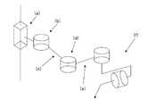
ロボットアームは、手術台近くに配置することのできる車輪付きの可動装着体上に実装してある(図1)。この装着体はシステムを不動化できるようにするブレーキ或いは類似のシステムを有しており、それはそれを簡単に移動させて可動装着体上方にロボットアームを案内させる把手もまた有する。装着体もアーム自体も共に、殺菌されたカバーでもって覆うことができる。前記マウントの基部には、コントローラと組立体へ電力を供給する電池システムとが存在する。操作アームの構造内にはインタフェースシステムの内部モジュールが存在し、指示入力手段を用いて外科医が述べた要望に従い被装着手術器具を動かすようロボットにとって適切な動き指示を生成する役割を担っている。インタフェースシステムのコントローラと電池と内部モジュールの組立体はロボットアームの基部に装着したボックス内に配置してあり、このロボットアームは残りのロボットとの類似の接続を用いて互いに完全に分解交換して修理或いは前述の要素の異なる実施形態間の切り換えを容易にすることができる。 The robot arm is mounted on a movable mounting body with wheels that can be placed near the operating table (FIG. 1). The mounting body has a brake or similar system that allows the system to be immobilized, and it also has a handle that easily moves it to guide the robot arm over the movable mounting body. Both the mounting body and the arm itself can be covered with a sterilized cover. At the base of the mount is a controller and a battery system that supplies power to the assembly. Within the structure of the operating arm is an internal module of the interface system, which is responsible for generating appropriate movement instructions for the robot to move the mounted surgical instrument according to the demands stated by the surgeon using the instruction input means. The interface system controller, battery and internal module assembly are placed in a box attached to the base of the robot arm, which can be completely disassembled and replaced with each other using similar connections with the rest of the robot. Repairs or switching between different embodiments of the aforementioned elements can be facilitated.
ロボットアーム(図2)は、第1の角柱継手(a)を有する。角柱継手は、第1の座標系のZ軸を移動する。第2の外旋継手(b)は、第1の座標系が規定するX−Y平面に対し平行な面内でロボットの第2の部材(c)を動かす。 The robot arm (FIG. 2) has a first prism joint (a). The prismatic joint moves along the Z axis of the first coordinate system. The second external rotation joint (b) moves the second member (c) of the robot in a plane parallel to the XY plane defined by the first coordinate system.
ロボット(c)の第2の部材は第3の継手(d)、すなわち同じく外旋継手に接合してあり、この継手がロボット(e)の第3の部材を継手(b)と同一平面内で動かす。この部材(c)は端部アクチュエータ(f)に接合され、このアクチュエータが内視鏡を確実に固締できるようにし、それが組立体に対し二つの受動的自由度を付加する。これらの二つの受動的自由度により内視鏡は確実に使用できるようになり、何故ならたとえ誤った動きが行われるとの事実にも拘わらず、それらがこの器具を動かしたときに患者の皮膚を傷めないようにするからである。好適な実施形態では、継手(a)は残りのロボットアームを固定した可動凹字楔を有する垂直直線変位装置の軸に結合されたエンジンを介して動作する。この継手(b)は、継手軸と同軸のエンジンを介して直接的に作動させることができる。一方、継手(d)は継手の一つ(b)と同じ軸上に位置するエンジンから継手(d)へ動きを伝達する伝達ベルトを介して動く。前記伝達ベルトはロボットアームの第2の部材の構造内部に隠してあり、それが外部からアクセスできないようにしてある。 The second member of the robot (c) is joined to the third joint (d), i.e., the external rotation joint, and this joint connects the third member of the robot (e) in the same plane as the joint (b). Move with. This member (c) is joined to the end actuator (f) to ensure that the actuator can clamp the endoscope, which adds two passive degrees of freedom to the assembly. These two passive degrees of freedom ensure that the endoscope can be used because the patient's skin when they move the instrument, despite the fact that false movements are made. It is because it is made not to hurt. In a preferred embodiment, the joint (a) operates via an engine coupled to the axis of a vertical linear displacement device having a movable concave wedge that secures the remaining robot arm. This joint (b) can be actuated directly via an engine coaxial with the joint shaft. On the other hand, the joint (d) moves through a transmission belt that transmits movement from the engine located on the same axis as one of the joints (b) to the joint (d). The transmission belt is hidden inside the structure of the second member of the robot arm so that it cannot be accessed from the outside.
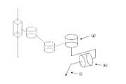
前述した端部アクチュエータは、ロボットの手首に固定される(図3)。それは2個の受動的継手(g),(h)を備えており、患者の腹部内に挿入していないときにそれらが手術器具を2個の自由度をもって動かせるようにしている。これらの2個の自由度により、それらが人がそれを操作したときと同じ仕方で器具の動きにより揺動点が当然に確立できるようにする限り、システムをより確実なものにできる。加えて、両継手はそれらが回動した角度(図3の図式には図示せず)の大きさを見出す手段を有していて、この値をシステムが利用可能にできるようにしてある。これらのセンサは、必ずしも後述する如くカメラに分与する動きを計算してそれを所望場所へ到達させる方法が適用できるようにする解決策ではなく、例えば電位差計や角度エンコーダとすることができる。計測時の冗長性を可能にする2個のセンサを軸ごとに設けることができ、それら二つの平均値を見出したり或いは起き得るセンサ故障を検出したりするかのいずれをも可能にするものである。両受動的継手は、第1の継手(g)をアーム回転の二つの継手と平行とし、一方で第2の継手(h)を第1の継手に垂直とし、両方がロボットに装着された手術器具の軸内で切断されるよう配置してある。この配置により、適切な配向をもって手術器具の作業空間全体に達する能力をシステムに与える必要のある第3の外旋継手及びそのアクチュエータを不要にできる。これは、システムのより大きな単純さと経済性とをもたらす。さらに、外科手術要素を保持するアダプタは該要素を確実かつ堅固に固締する手段を有しており、この手段が同時にどんな工具も用いずに内視鏡から光学系を素早く取り除けるようにする。図4は考え得るアダプタの実施形態を示すものであり、ここで受動的継手(g),(h)と腹腔鏡検査カメラの光学系(j)を評価することができる。 The aforementioned end actuator is fixed to the wrist of the robot (FIG. 3). It comprises two passive couplings (g), (h) that allow the surgical instrument to move with two degrees of freedom when not inserted into the patient's abdomen. These two degrees of freedom can make the system more reliable as long as they allow the swing point to be established by the movement of the instrument in the same way that a person has manipulated it. In addition, both joints have means to find the magnitude of the angle they are rotated (not shown in the diagram of FIG. 3) so that this value can be made available to the system. These sensors are not necessarily solutions that allow the application of a method of calculating the motion distributed to the camera and reaching it to the desired location, as will be described later, but can be, for example, potentiometers or angle encoders. Two sensors can be provided for each axis to enable redundancy during measurement, and it is possible to either find the average of these two values or detect possible sensor failures. is there. Both passive joints have a first joint (g) parallel to the two joints of arm rotation, while the second joint (h) is perpendicular to the first joint and both are attached to the robot. It is arranged to be cut in the axis of the instrument. This arrangement eliminates the need for a third external swivel joint and its actuator that need to give the system the ability to reach the entire working space of the surgical instrument with proper orientation. This leads to greater simplicity and economics of the system. In addition, the adapter holding the surgical element has a means for securely and securely clamping the element, allowing this means to quickly remove the optics from the endoscope at the same time without using any tools. FIG. 4 shows a possible adapter embodiment in which the passive couplings (g), (h) and the laparoscopic camera optics (j) can be evaluated.
安全性を改善するため、ロボットアームはシステムを作動させるのに必要な配線全体をそこに通過させてコネクタを隠し、かくしてシステムの機能不全を招くことのある手術室からの他の材料や他の物体或いは手術室内で作業する人さえも一切引っかけないようにする一定の空間をその中に有する。 To improve safety, the robotic arm passes through all the wiring necessary to operate the system to conceal the connector and thus other materials and other materials from the operating room that can lead to system malfunction. It has a certain space in it that prevents any objects or even people working in the operating room from getting caught.
それを接続したときのロボットアームの初期位置を知るべく、システムの通常の性能に対する障害を伴うことなく或いは外部からアクセス可能とすることなく継手の前記初期位置を特定できるようにする手段が設けてある。これらの手段は、継手の平行軸内に位置するセンサ(或いは角柱(a)内では利用可能なアクチュエータの軸に平行)内で第1(a)と第2(b)の電動継手(角柱継手と第1の外旋継手)で出来ていて、それらが前記軸に対し垂直な平面内に位置し、ロボットアームの第2の部材(c)(これが第2の継手(b)を第3の継手(d)に接合させる)に一体の円形部分の一部を検出する。本発明の好適な実施形態では、前記部品はその一部が残りの部分よりも大きな半径を有するディスクで出来ており、前記センサを実在センサとし、これにより継手の回動空間の一部において、前記センサがより大径を有する部分を検出し、それ以外は何も検出しないようにしてある。本発明の他の代替実施形態では、センサは(一例で、限定はしない)画像センサや磁気センサ或いは接触センサとすることができる。それ故、継手軸上に装着された部分は例えば所与のセンサの特性に適したものとしなければならず、それぞれ異色の二つの扇形部や異なる磁気特性からなる二つの材料や或いは前述の接触センサに接触或いは接触させない二つの異なる高さを有するディスクを有する。 In order to know the initial position of the robot arm when it is connected, means are provided to allow the initial position of the joint to be identified without impeding the normal performance of the system or being externally accessible. is there. These means are the first (a) and second (b) electric couplings (rectangular couplings) in a sensor (or parallel to the axis of the available actuator in the prism (a)) located in the parallel axis of the coupling. And the first external rotation joint), which are located in a plane perpendicular to the axis, and the second member (c) of the robot arm (this connects the second joint (b) to the third joint). A part of the circular part integral with the joint (d) is detected. In a preferred embodiment of the present invention, the part is made of a disk having a part having a larger radius than the remaining part, and the sensor is a real sensor, whereby a part of the rotation space of the joint is The sensor detects a portion having a larger diameter, and does not detect anything else. In other alternative embodiments of the invention, the sensor may be an image sensor, a magnetic sensor, or a contact sensor (by way of example and not limitation). Therefore, the part mounted on the joint shaft must be suitable for the characteristics of a given sensor, for example, two differently colored sectors or two materials with different magnetic properties or the aforementioned contact It has a disc with two different heights that will or will not contact the sensor.
継手の初期位置を特定するため、前述の構成には所定の方法が組み合わされる。
1)ロボットアームを始動させると、センサが継手軸上に装着された部分の個々の扇形部の存在を検出しているかどうか照査する(本発明の好適な実施形態では、ディスクの一部がより大きな半径を有する)。
2)検出された場合、継手はそれがもはや検出されなくなるまで動かす。
3)検出されなかった場合、継手はそれが他の事例において動く向きとは逆の向きで検出されるまで動かす。In order to specify the initial position of the joint, a predetermined method is combined with the above-described configuration.
1) When the robot arm is started, it checks whether the sensor detects the presence of individual sectors of the part mounted on the joint axis (in a preferred embodiment of the invention, a portion of the disk is more Have a large radius).
2) If detected, the joint moves until it is no longer detected.
3) If not detected, move the joint until it is detected in the opposite direction to that in other cases.
この方法を用い、その部分の個々の扇形部の幅を知ることで、ロボットアームの初期位置を見出すことが可能である。 Using this method, it is possible to find the initial position of the robot arm by knowing the width of each sector in that part.
第3の電動継手(d)(第2の外旋継手)の場合、同様の構成が存在するが、センサを検出する部分は第3の継手(d)のエンジンからその継手軸まで延びる伝達ベルト内の一点に一体的に固定してあり、このセンサは作動させた第2と第3の継手(それぞれ(b)と(d))を接合するロボットの部材(c)内部の既知の位置に固定してある。かくして、ロボットアームを接続すると、第3の電動継手(d)が前述した方法に従って動き、同様に、伝達チェーンに対するセンサ及び一体型要素の位置を知ることで継手の初期位置を知ることが可能である。本発明の好適な実施形態では、センサを検出する要素は伝達ベルトに取り付けた側面を有するL形状部分であり、センサは実在センサである。 In the case of the third electric joint (d) (second external rotation joint), there is a similar configuration, but the part for detecting the sensor is a transmission belt extending from the engine of the third joint (d) to the joint shaft. The sensor is integrally fixed at one point, and this sensor is located at a known position inside the robot member (c) that joins the activated second and third joints (respectively (b) and (d)). It is fixed. Thus, when the robot arm is connected, the third electric joint (d) moves according to the method described above, and similarly, it is possible to know the initial position of the joint by knowing the position of the sensor and the integral element with respect to the transmission chain. is there. In a preferred embodiment of the present invention, the sensor detecting element is an L-shaped part having a side attached to the transmission belt, and the sensor is a real sensor.
ロボットアームのコントローラは、その可動装着体の基部に配置してある。コントローラはロボット(かくして、端部アクチュエータを含む)の能動的継手と受動的継手のそれぞれに配置された位置センサから入来する信号を受信し、これによりデナビット−ハルテンベルグ規約(図5参照)に従ってロボットアームに沿う幾つかの座標系を確立して得られるものから順運動学モデルを介して常時その位置を知ることができるようになる。 The controller of the robot arm is arranged at the base of the movable mounting body. The controller receives incoming signals from position sensors located at each of the active and passive couplings of the robot (thus including end actuators), thereby allowing the robot to comply with the Denabit-Hartenberg convention (see FIG. 5). It becomes possible to know the position at all times through the forward kinematic model from what is obtained by establishing several coordinate systems along the arm.
同様に、ロボットアームの逆運動学モデルと経路立案(位置と速度と加速度)とロボット内に配置された角度センサが提供する情報とを用い、前記したコントローラが後述する方法を用いて表明された外科医の指示に従って被装着器具を所望位置に到達させるのに必要な動作を計算する。 Similarly, using the inverse kinematic model of the robot arm, path planning (position, velocity, and acceleration) and information provided by the angle sensor placed in the robot, the above-mentioned controller was expressed using the method described later. According to the surgeon's instructions, the motion necessary to bring the mounted device to the desired position is calculated.
ロボットアームのコントローラは、初期位置から最終位置への移動期間中に器具の目標位置を動的に計算する方法で、事前の較正或いは手術台への組立体の固定の必要性を取り除く方法を実行する十分な容量を有していなければならない。さらに、端部アクチュエータの受動的継手上に装着されたセンサには、前述の方法が効果的に適用できるようにする十分な分解能を持たせなければならない。 The robot arm controller performs a method that dynamically calculates the target position of the instrument during the movement from the initial position to the final position, eliminating the need for pre-calibration or securing the assembly to the operating table Must have enough capacity to do. Furthermore, the sensor mounted on the passive coupling of the end actuator must have sufficient resolution so that the method described above can be applied effectively.
理想的には、挿入点の位置が精度をもって既知である場合、外科医が一旦指示を与えると、器具の外端部の所望の位置が術具の現在の向きと位置と旋回半径(すなわち、外端部から挿入点までの術具の軸に沿う距離)とに従って計算され、一旦目標位置に達すると、受動的継手と術具の挿入点により定まる支持点とを通じ、前記術具は所望の向きと位置とを取る。しかしながら、挿入点が正確に判らない場合、これは図6に示す状況を招く。図6aは平面図を示し、図6bは側面図を示す。実際の挿入点(l)は誤計算され、それに代えて(k)が用いられる。このシステムは点(m)から始め所望目標としての(n)に達するが、指示点と方向半径が異なるため、計算される目標位置は(n)ではなく(o)となり、誤った旋回半径を用いて計算される回動を器具にもたらす。これらは不適切な向きと最終位置を招き、そのことがシステムの性能を減退させたり、或いはロボットアームを手術台に物理的に固定するよう強制したり、或いはロボットアームに関する挿入点の場所を初期計算させる。 Ideally, if the position of the insertion point is known with accuracy, once the surgeon gives instructions, the desired position of the outer end of the instrument will be the current orientation and position of the instrument and the turning radius (ie, outer radius). The distance from the end to the insertion point along the axis of the surgical instrument), once the target position is reached, the surgical instrument is in the desired orientation through the passive joint and the support point defined by the insertion point of the surgical instrument. And take with the position. However, if the insertion point is not known accurately, this leads to the situation shown in FIG. 6a shows a plan view and FIG. 6b shows a side view. The actual insertion point (l) is miscalculated and (k) is used instead. This system starts from the point (m) and reaches the desired target (n), but since the direction radius is different from the indicated point, the calculated target position is (o) instead of (n), and the wrong turning radius is set. Bring to the instrument a rotation calculated using. These can lead to improper orientation and final position, which can reduce system performance, force the robot arm to be physically fixed to the operating table, or initially place the insertion point for the robot arm. Let it be calculated.
本発明では、初期位置から最終位置へのその遷移期間中に器具の目標位置を動的に計算する一つの方法が用いられ、挿入点(l)の位置を再送し、装置を手術台に繋ぎ止めたり或いはロボットアームが外科手術に参加する前に較正したりすることなく、目標位置と向きに達する過程での誤差を除去する。 In the present invention, one method is used to dynamically calculate the target position of the instrument during its transition from the initial position to the final position, retransmitting the position of the insertion point (l) and connecting the device to the operating table. Remove errors in the process of reaching the target position and orientation without stopping or calibrating the robot arm before participating in the surgery.
初期時点では、器具は挿入点(l)(支点)内に挿入され、その外端部は同様に公知の向きを有する既知の位置にある。外科医が指示を与えると、これが内端部の新規所望位置をもたらし、それがひいては患者外部の端部の新規所望位置とその新規の所望の向きを意味する。そこへの到達は、挿入点(l)の位置を正確に知る方法に依存する。図7の線図によれば、目標に到達できるよう制御適応則が初期位置から最終位置へ移行する各瞬間ごとに弧の所要値を計算し、またカバーされた実際の弧の長さを用い、実際の向きと推定旋回半径(すなわち、器具の軸に沿う挿入点(l)までの推定距離)これら全てを各瞬間ごとに計算する。この所要弧は推定旋回半径を有する動的な経路発生器に用いられ、各瞬間ごとに継手基準値を新規計算に従って補正するロボットアームの伝達継手について作製され、この計算が受動的継手を介して所望の向きに達する被装着器具の所定の動きを最終的に分与する。 Initially, the instrument is inserted into the insertion point (l) (fulcrum) and its outer end is in a known position with a known orientation as well. When given by the surgeon, this results in a new desired position of the inner end, which in turn means the new desired position of the outer end of the patient and its new desired orientation. Reaching there depends on how to know exactly the position of the insertion point (l). According to the diagram of FIG. 7, the required value of the arc is calculated at each instant when the control adaptation law moves from the initial position to the final position so that the target can be reached, and the actual arc length covered is used. The actual orientation and the estimated turning radius (ie, the estimated distance to the insertion point (l) along the instrument axis) are all calculated at each instant. This required arc is used for a dynamic path generator with an estimated turning radius and is created for a robot arm transmission joint that corrects the joint reference value according to a new calculation at each moment, and this calculation is performed via a passive joint. A predetermined movement of the mounted device that reaches the desired orientation is finally dispensed.
前述の方法を、ここでより詳細に説明する。システムへの入力は器具の所望の向きであり、それは垂直旋回軸に従うか或いは水平旋回軸に従うかのいずれかとすることができる(いずれの場合も、角度のうちの一つだけであり、何故ならそれらは止めることができる問題であって、それらは同一の方法を用いて個別に計算されるからである)。この所望の向きに合わせ、第1の指示の時間則はこの種向きに達するよう器具の端部がカバーする直線中の長さに従って関連付けられる。 The foregoing method will now be described in more detail. The input to the system is the desired orientation of the instrument, which can either follow the vertical or horizontal pivot axis (in each case only one of the angles, because They are problems that can be stopped, since they are calculated separately using the same method). In accordance with this desired orientation, the time rule of the first indication is related according to the length in the straight line that the end of the instrument covers to reach this kind of orientation.

ここで、L(t)は時間に応じて器具端部が達する直線長であり、τはシステムの時定数であり、Kはシステムの静的ゲインであり、u(t)は器具の向きとその旋回半径(すなわち、受動的継手の軸が器具内で交差する点から患者内の前記器具の挿入点までの距離)の関数である所望の弧長である。 Where L (t) is the linear length reached by the instrument end as a function of time, τ is the system time constant, K is the system static gain, and u (t) is the instrument orientation and A desired arc length that is a function of its turning radius (ie, the distance from the point where the axis of the passive joint intersects within the instrument to the point of insertion of the instrument within the patient).
離散時間における前述の式は、下記の形式を有する。 The above equation in discrete time has the following form:
ここで、L(k)は時刻kにおいて器具端部がカバーする直線長であり、τはシステムの時定数であり、Tは離散化サンプリング周期であり、Kはシステムの静的ゲインであり、urは器具の向きとその旋回半径(すなわち、受動的継手の軸が器具内で交差する点から患者内の前記器具の挿入点までの距離)の関数である所望の向きに達する上でカバー対象となる弧長である。この後半の旋回半径は未知であり、このことが被装着器具を配置する向きと位置の精度に影響を及ぼす。Where L (k) is the linear length covered by the instrument end at time k, τ is the system time constant, T is the discretization sampling period, K is the system static gain, ur cover on reaching the desired orientation is a function of orientation and its turning radius of the device (i.e., the distance from the point where the axis of the passive joints intersect in the instrument to the insertion point of the instrument in the patient) The target arc length. The turning radius of this latter half is unknown, and this affects the accuracy of the orientation and position of the mounted device.
前述した知識の欠落により生ずる誤差を取り除くため、二つの状態変数を用いて状態空間内に制御則を確立するが、それらは器具の端部により直線にてカバーする長さLと、生じた角度誤差を表わす状態変数である。前記制御則を得るため、下記を状態式を用いる。 In order to eliminate the error caused by the lack of knowledge described above, a control law is established in the state space using two state variables, which are the length L covered by the straight line by the end of the instrument and the resulting angle. It is a state variable representing an error. To obtain the control law, the following equation is used.
ここで、L(k)は時刻kにおいて器具端部が直線にてカバーする長さであり、v(k)は時刻kにおける器具の向きに生ずる角度誤差であり、τはシステムの時定数であり、Tは離散化サンプリング周期であり、kpは旋回半径であり、Kはシステムの静的ゲインであり、u(k)は各瞬間kにおける所望の向きに達する上でカバー対象となる弧長である。Here, L (k) is the length that the end of the instrument covers in a straight line at time k, v (k) is the angular error that occurs in the orientation of the instrument at time k, and τ is the system time constant. Yes, T is the discretization sampling period, kp is the turning radius, K is the static gain of the system, and u (k) is the arc to be covered in reaching the desired orientation at each instant k. It is long.
この点から、下記の適応制御則が得られる。 From this point, the following adaptive control law is obtained.
ここで、u(k)は各時刻kごとに所望の向きに達する上でカバー対象となる弧長であり、kpは旋回半径であり、水平軸に沿う向きの場合はkp値=p(ここで、pは推定旋回半径)であり、垂直軸に沿う向きの場合はkp値=sin(β)(ここで、βは垂直に対する器具の角度である)であり、r(k)は各時刻kごとの所望の向きで、鋭く展開しないよう前述の時間則に従って記述される第1の指示システムに関する台形輪郭に従い各時刻ごとに修正され、H(k)はシステムがその目標に到達するための選択されたゲイン行列であり、L(k)は時刻kにおいて器具端部がカバーする直線長であり、v(k)は時刻kにおいて器具の向きに生じた角度誤差である。それ故、適応制御則には光学系の向き(端部アクチュエータ上に装着されたセンサを用いて計測)と誤差の計算に望まれる向きと推定旋回半径pとカバーされた弧長L(k)とが必要となる。Here, u (k) is the arc length to be covered when reaching the desired direction at each time k, kp is the turning radius, and in the case of the direction along the horizontal axis, kp value = p (Where p is the estimated turning radius), and in the case of orientation along the vertical axis, kp value = sin (β) (where β is the angle of the instrument relative to the vertical) and r (k) Is corrected at each time according to a trapezoidal profile for the first pointing system described in accordance with the time rule described above, in a desired orientation at each time k, so as not to develop sharply, and H (k) is reached by the system at its target. L (k) is the linear length covered by the instrument end at time k, and v (k) is the angular error that occurred in the orientation of the instrument at time k. Therefore, the adaptive control law includes the orientation of the optical system (measured using a sensor mounted on the end actuator), the desired orientation for error calculation, the estimated turning radius p, and the covered arc length L (k). Is required.
適応制御則の結果は所要の弧長であり、これが先に示した下記の状態式で構成される状態の予測器を介して器具の端部に共に関係する弧長と速度を計算する時点まで、カバーした実際の弧長の推定と合わせ用いられる。 The result of the adaptive control law is the required arc length, up to the point of calculating the arc length and velocity that are both related to the end of the instrument via the state predictor composed of Used in conjunction with the estimation of the actual arc length covered.
ここで、異なる大きさは先に説明したのと同じ意味を有する。 Here, the different sizes have the same meaning as described above.
この二重の結果は速度変化図計算用の入口及び端部アクチュエータが追従する経路として用いられ、その両方の場合ともその瞬間まで実際の弧長の推定を入口として用い、加えて経路の場合には、推定旋回半径pの裏付けと共に用いる。得られた端部アクチュエータのデカルト座標系速度と経路からロボットアームの逆運動学モデルを用いることで、継手基準値が導出され、それがロボットアームの継手に伝えられて目標場所に達する。この動きが端部アクチュエータを動かし、これが受動的継手と(実際の)挿入点である支持点とを介して被装着器具を新たな向きに到達させる。ロボットアームの継手に新たな継手基準値が送信されるのと同時に、ロボットアームの前記継手基準値と直接的な運動学モデルを介し、かつ先に示した状態式(ここでは状態推定器として機能する)に従い、これまでにカバーした実際の弧の推定が第1のステップにおいて得られ、次のステップにおいて旋回半径推定器の助けを借り、この場合も端部アクチュエータのセンサを介する光学系の実際の向きを入口として用い、前記推定旋回半径pが得られる。ロボットアームコントローラは、各能動的自由度のためのコントローラと、外科医が与えインタフェースシステムを介して受信した指示に従うとともに前述の方法に従い、その初期位置及び向きから最終位置及び向きまでの直線を記述する被装着器具がカバーする必要のある一連の位置だけでなく、所望場所に到達する上で被装着器具用にロボットの電動継手が採用しなければならない最終位置もまた計算する監視装置とを含む階層的アクチュエータ(図8参照)を有する。この一連の継手位置は、各継手をその目標に到達させることを担うコントローラへ送信される。ロボットアームのコントローラ内に介在する異なる要素間の通信は、専用バスを介して達成される。好適な実施形態では、コントローラは監視レベルに合わせた電子回路や同様の他の3個の電子回路を介して実装され、電動継手のコントローラごとに相互交換可能としてある。コントローラと合わせ、端部アクチュエータが装備する異なるセンサが送信する信号を受信してそれらを監視装置へ送信する手段もまた存在する。これらの手段は、好適な実施形態にあっては、電子回路を介して同様に実装される。 This double result is used as the path followed by the inlet and end actuators for velocity change diagram calculation, both of which use the actual arc length estimate as the inlet until that moment, plus in the case of the path Is used together with the support of the estimated turning radius p. By using the inverse kinematic model of the robot arm from the obtained Cartesian coordinate system velocity and path of the end actuator, the joint reference value is derived and transmitted to the joint of the robot arm to reach the target location. This movement moves the end actuator, which causes the device to be mounted to reach a new orientation through the passive coupling and the (actual) insertion point support point. A new joint reference value is sent to the joint of the robot arm, and at the same time, through the joint reference value of the robot arm and a direct kinematic model, the state equation shown here (functioning as a state estimator here) The actual arc estimate so far covered is obtained in the first step, with the help of the turning radius estimator in the next step, again in this case the optical system actual via the sensor of the end actuator. Is used as the entrance to obtain the estimated turning radius p. The robot arm controller describes a straight line from its initial position and orientation to its final position and orientation according to the method described above and in accordance with the instructions given by the surgeon and received via the interface system, with a controller for each active degree of freedom. Hierarchy that includes not only a series of positions that must be covered by the wearable device, but also a monitoring device that calculates the final position that the robotic motor joint must employ for the wearable device to reach the desired location With a mechanical actuator (see FIG. 8). This series of joint positions is transmitted to the controller responsible for causing each joint to reach its target. Communication between different elements intervening in the controller of the robot arm is achieved via a dedicated bus. In a preferred embodiment, the controller is implemented via an electronic circuit tailored to the monitoring level or other three similar electronic circuits, and is interchangeable for each controller of the electric coupling. There are also means for receiving the signals transmitted by the different sensors equipped with the end actuator in combination with the controller and transmitting them to the monitoring device. These means are similarly implemented via electronic circuits in the preferred embodiment.
コントローラに付属し、さらにロボットアームの基部にさえ、外科医の指示を受け取り、それらに応答してロボットに適した動きの指示を発生するモジュールが設けてある。同様に、この内部モジュールが指示入力手段との通信を担っている。この内部モジュールの実施形態は、ユーザが選択する指示入力手段に応じて可変することができる。好適な実施形態では、それはマイクロフォンを介してユーザが与える被発声指示の認識を担う特化された電子回路で出来ているが、それはまたデジタル信号プロセッサや個人向け携帯情報端末(PDA)や或いはアームの機械構造に一体化されたミニコンピュータ等の汎用目的を有する機械内で実行されるプログラムの形を取らせることもできる。 A module attached to the controller and even at the base of the robot arm is provided for receiving the surgeon's instructions and responsively generating movement instructions suitable for the robot. Similarly, this internal module is responsible for communication with the instruction input means. This embodiment of the internal module can vary depending on the instruction input means selected by the user. In the preferred embodiment, it is made of specialized electronic circuitry that is responsible for recognizing spoken instructions given by the user via a microphone, but it can also be a digital signal processor, personal digital assistant (PDA) or arm It is also possible to take the form of a program executed in a machine having a general purpose such as a minicomputer integrated with the machine structure.
同様に、口頭指示が選択されないか或いはロボットと相互作用することがユーザにとっての唯一の可能性でないシステムの別の実施形態では、前述のモジュールはタッチスクリーン(ただし、これに限定はされない)等の他の指示入力手段の制御を担う。前述の追加の制御手段の信号と音声インタフェースを介して受信した支持の両方が、内部モジュール内でロボットコントローラに送信する指示へ変換される。これらは、アームが行う必要のある動きを示す。 Similarly, in another embodiment of the system where verbal instructions are not selected or interacting with the robot is not the only possibility for the user, the aforementioned module may be a touch screen (but not limited to) Responsible for controlling other instruction input means. Both the signal of the additional control means and the support received via the voice interface are converted into instructions to be sent to the robot controller in the internal module. These indicate the movements that the arm needs to make.
指示入力手段として、本システムの好適な実施形態では、ロボットアームに装着したジョイスティックや制御レバーとロボットアーム内の構造に配置され或いは外科医が保持する好ましくは無線(ただし、従来のものにもできる)のマイクロフォンが設けてある。しかし、これにはユーザがそれをより好都合な位置に配置できるようにする関節機構を用いてロボット構造に装着するタッチスクリーン等の他の入力手段を持たせることもできる。このスクリーン内には腹腔鏡検査画像が存在し、その頂部に手術に関するヘルプ記号やシステムの状態や手術室の他の器具の性能に関する情報や或いは他の関心のある情報等の異種情報を示すことができる。他の制御手段は、例えば(これに限定はされないが)ロボットが保持する手術器具の形を再生する主操作器で、該主操作器の位置の修正がインタフェースシステムの内部モジュールが行う適切な変換を介し、操作器に装着された手術器具におけ同様の動きを意味する主操作器を含めることができる。この主操作器には、ユーザが動き変換時にゲインK或いは減衰K−1を特定できるようにする手段を持たせ、かくして所定方向の長さLの動きが対応する方向に実際の術具を大きさK・L或いはK−1・Lでそれぞれ動かせるようにする手段を持たせることができる。別の可能性は、手術の準備(端部アクチュエータに未だ固定されていない手術器具を用いる)に限定されるが、ロボットに対し器具を固定するより好都合な点に配置されるまで手で直接的にロボットアームを動かすことからなり、それは第2と第3の操作継手(b),(d)を非被制御とし、器具の固定時にユーザからの特別な指示をもって制御を回復することで達成される。As an instruction input means, in a preferred embodiment of the system, a joystick or control lever attached to the robot arm and a structure within the robot arm are preferably arranged or held by the surgeon (but can also be conventional). The microphone is provided. However, it can also have other input means such as a touch screen that attaches to the robotic structure using a joint mechanism that allows the user to place it in a more convenient position. There is a laparoscopic image in this screen, and the top of it shows different information such as help symbols for surgery, system status, information about the performance of other instruments in the operating room, and other information of interest Can do. The other control means is, for example (but not limited to), a main controller that reproduces the shape of the surgical instrument held by the robot, and correction of the position of the main controller is performed by an internal module of the interface system. The main operation device which means the same movement in the surgical instrument attached to the operation device can be included. The main controller is provided with means for allowing the user to specify the gain K or the attenuation K−1 at the time of motion conversion, and thus the actual surgical tool is enlarged in the direction corresponding to the movement of the length L in the predetermined direction. It is possible to have means for allowing movement by K · L or K−1 · L. Another possibility is limited to surgical preparation (using surgical instruments not yet secured to the end actuators), but directly by hand until placed at a more convenient point to secure the instrument to the robot. This is achieved by uncontrolling the second and third operation joints (b) and (d) and restoring the control with a special instruction from the user when the instrument is fixed. The
コントローラに付属するインタフェースの内部モジュールは、これに限定はしないが例えば手術器具の実際の位置を表わす線図や動きが危険である領域等の異なる情報をユーザに提示する役割もまた担うものである。同様に、ロボットがとった動きの記録とシステムが占有した位置の記録を保存し、必要に応じてその後の言葉或いは音声の再構成を可能にできる。それは、システムのセットアップを可能にするシステムの状態に関し言葉或いは音声の形で音声情報を返すこともできる。かくして、例えば行おうとする手術の留意内容に従ってロボットアームに関し「左アーム」又は「右アーム」の初期構成を選択し、第3の電動継手(第2の外旋継手)を外科医から遠ざけて彼又は彼女を邪魔しないようにすることが可能である。別の例は、手術中に外科医が与える指示に応じて患者内部の手術器具の端部に与える動きの大きさの外科医の必要ないしは嗜好に従った選択からなる。 The internal module of the interface attached to the controller also plays a role of presenting different information to the user such as, but not limited to, a diagram representing the actual position of the surgical instrument and an area where movement is dangerous. . Similarly, a record of the movement taken by the robot and a record of the position occupied by the system can be saved, allowing subsequent word or voice reconstruction as needed. It can also return audio information in the form of words or sounds regarding the state of the system that allows system setup. Thus, for example, according to the considerations of the operation to be performed, the initial configuration of the “left arm” or “right arm” is selected for the robot arm and the third motorized joint (second external rotation joint) is moved away from the surgeon or he or It is possible not to disturb her. Another example consists of selecting according to the surgeon's need or preference for the amount of movement to be applied to the end of the surgical instrument inside the patient in response to instructions given by the surgeon during the operation.
組立体(コントローラ付き操作アームとインタフェースシステムの内部モジュールと手術室内に在る指示入力手段が含まれる)を電池動作させ、そのことがそれを使用する手術室の電装に独立性をもたらし、その用途ならびに開発を簡単化する。 The assembly (including the operating arm with controller and the internal module of the interface system and the instruction input means located in the operating room) is operated by a battery, which brings independence to the electrical equipment of the operating room that uses it. As well as simplifying development.
本システムは、外科手術分野、特に最小侵襲性外科手術に対しロボットの正確かつ安全な特徴を適用できるようにする。腹腔鏡検査カメラの移動に用いたときに、より安定した画像(それ無しでは手術時間に影響する)や医局員間のより良き調整や手術時間の低減(それがひいては患者が麻酔下にある時間を低減する)等の一連の利点が得られる。さらに、ロボットシステムに対し外科医が指示を与える手段としての音声認識システムの使用が彼又は彼女が助手の助け無しで追加の器具を扱えるようにし、そのことが最小侵襲性手術の技術内で複雑な仕事を簡単に行えるようにする。器具の追従場所を計算するのに用いる方法のお陰で、ロボットアームは手術室内により低いコストでもって簡単に組み込むことができ、何故ならロボットアームを繋ぎ止めるよう手術台を修正(或いはその変更すら)する必要はなく、器具の挿入場所を見出すために手術前に較正を行う必要もなく、そのことが手術の持続時間を短縮してシステムの償却を改善し、何故ならそれが同じ手術中においてさえ一つの外科措置から別の措置への素早い変更を可能にするからである。この容易さの品質と組み込み経済性は、電池動作とすることにで強化される。 The system allows the robot's accurate and safe features to be applied to the surgical field, particularly minimally invasive surgery. When used to move the laparoscopic camera, more stable images (without it will affect the operation time), better coordination between medical staff and reduction of the operation time (and thus the time the patient is under anesthesia) A series of advantages are obtained. Furthermore, the use of a speech recognition system as a means for the surgeon to give instructions to the robotic system allows him or her to handle additional instruments without the assistance of an assistant, which is complicated within the art of minimally invasive surgery. Make work easier. Thanks to the method used to calculate the follow-up location of the instrument, the robot arm can be easily integrated into the operating room at a lower cost because the operating table has been modified (or even changed) to keep the robot arm in place. There is no need to calibrate before surgery to find out where to insert the instrument, which shortens the duration of the surgery and improves system depreciation, even during the same surgery This is because it allows a quick change from one surgical procedure to another. This ease of quality and built-in economy is enhanced by battery operation.
Claims (12)
Translated fromJapanesea)最初の時点で前記器具を入口点(すなわち、支点)内に挿入し、その外端部を既知の向きをもって既知の位置に置き、
b)外科医が指示を与えたときに、これが内端部の新規所望位置へ招き、そのことがひいては患者外部の端部の新規所望位置とその新規所望の向きとを意味し、それらの到達が前記挿入点の場所をどの程度正確に知っているかに依存し、
c)前記所望の向きから、適応制御則が初期位置と対象を到達させる最終位置との間の経路の各瞬間ごとに必要な弧の長さを計算し、またカバーした実際の弧長及び計算された旋回半径(すなわち、挿入点までの器具の軸に従う推定距離)もまた用い、全てを各瞬間ごとに計算し、
d)この所要弧を推定旋回半径と合わせ動的経路発生器内で使用し、かくして各瞬間ごとに継手基準値をロボットアームの電動継手ごとに生成し、それを新規計算に従って補正し、最終的に被装着器具に動きを与え、この器具が受動的継手を介して所望の向きに至る、ことを特徴とするシステム。A robotic system that supports minimally invasive surgery that does not attach to the operating table, does not require pre-calibration of the insertion point, and can position the surgical instrument in response to instructions from the surgeon. It has two degrees of freedom and two passive degrees (three are active), the first one is a prism, the second and third are pivotable, they are shown in FIG. As shown in FIG. 3, a robot arm and two passive ones arranged so as to be found to be located mutually are arranged perpendicular to each other as shown in FIG. For end-arm actuators that can be held for internal use and robotic arms integrated into their mechanical structure, requiring the system to be physically fixed to the operating table, or where the instrument is inserted Need pre-calibration to estimate A controller capable of performing a method of calculating a given movement for causing a held surgical instrument to reach a desired location with accuracy, and an interface system for instructing the system to perform a desired operation, which is added to the robot controller. A movable mounting comprising a module and an interface system which also includes means for providing said instructions, battery operated for the entire assembly and having brakes or wheels with similar devices that allow it to be safely immovable A system for placing on the body and calculating the movement that the method described above gives to the surgical instrument,
a) Insert the instrument into the entry point (ie, fulcrum) at the first time and place its outer end in a known position with a known orientation;
b) When the surgeon gives instructions, this leads to a new desired position at the inner end, which in turn means the new desired position at the outer end of the patient and its new desired orientation. Depends on how accurately you know the location of the insertion point,
c) From the desired orientation, the adaptive control law calculates the arc length required for each moment of the path between the initial position and the final position to reach the object, and the actual arc length and calculation covered. The calculated turning radius (ie the estimated distance according to the instrument axis to the insertion point) is also used, all calculated for each moment,
d) This required arc is combined with the estimated turning radius and used in the dynamic path generator, thus generating a joint reference value for each motor arm joint of the robot arm at each moment, correcting it according to the new calculation, and finally The system is characterized in that the device is subjected to movement, and the device reaches a desired orientation via a passive coupling.
・前記ロボットアームを始動させたときに、前記センサが前記継手軸上に装着された部分の個々の扇形部(本発明の好適な実施形態では、ディスクの一部がより大きな半径を有する)の存在を検出したかどうか照査し、
・検出した場合、この継手をそれがもはや検出されなくなるまで動かし、
・検出されなかった場合、この継手をそれが他の場合に動く方とは反対の方向を向くまで動かす
方法を用いて見出すことができる、手術台に装着せず挿入点の事前較正を必要としない請求項1,2,3のいずれか1項に記載の最小侵襲性外科手術用ロボットシステム。Means for allowing the initial position of the robot arm to be identified when it is connected, which do not interfere with the normal behavior of the system or are accessible from the outside, the means comprising: The second (b) non-movable joint (first external rotation joint) consists of a sensor arranged on the parallel axis of the joint rotation, which is located in a plane perpendicular to the axis. And detecting a part of a circular portion integral with the second member (c) of the robot arm (joining the third joint (d) to the second joint (b)), In the case of (d) (second external rotation joint), it is detected that the sensor is integrally fixed at a predetermined point in the transmission belt extending from the engine of the third joint (d) to the joint shaft. The same configuration except for the portion is provided, and the sensor is connected to the second and second sensors. The robot is fixed at a known position inside the robot member to which the joint is to be joined. Thus, the location of the sensor and the element for detecting the location of the sensor itself is known, and the location of the joint is determined as follows: Whether the sensor detected the presence of individual sectors (in the preferred embodiment of the invention, a portion of the disk has a larger radius) of the portion mounted on the joint shaft when it was started Please check
If detected, move this fitting until it is no longer detected,
If not detected, this joint can be found using a method that moves it in the opposite direction to the one that moves in other cases, requiring no pre-calibration of the insertion point without being mounted on the operating table. The minimally invasive surgical robot system according to any one of claims 1, 2, and 3.
Applications Claiming Priority (2)
| Application Number | Priority Date | Filing Date | Title |
|---|---|---|---|
| ES200602091AES2298051B2 (en) | 2006-07-28 | 2006-07-28 | ROBOTIC SYSTEM OF MINIMALLY INVASIVE SURGERY ASSISTANCE ABLE TO POSITION A SURGICAL INSTRUMENT IN RESPONSE TO THE ORDER OF A SURGEON WITHOUT FIXING THE OPERATING TABLE OR PRIOR CALIBRATION OF THE INSERT POINT. |
| PCT/ES2007/000442WO2008012386A1 (en) | 2006-07-28 | 2007-07-18 | Robotic system for assisting in minimally-invasive surgery, which can position a surgical instrument in response to orders from a surgeon, is not attached to the operating table and does not require pre-calibration of the insertion point |
Publications (1)
| Publication Number | Publication Date |
|---|---|
| JP2009544383Atrue JP2009544383A (en) | 2009-12-17 |
Family
ID=38981169
Family Applications (1)
| Application Number | Title | Priority Date | Filing Date |
|---|---|---|---|
| JP2009521282APendingJP2009544383A (en) | 2006-07-28 | 2007-07-18 | Robot system that supports non-invasive surgery that can position surgical instruments according to instructions from the surgeon without attaching to the operating table or pre-calibrating the insertion point |
Country Status (5)
| Country | Link |
|---|---|
| US (1) | US20090326324A1 (en) |
| EP (1) | EP2047805A1 (en) |
| JP (1) | JP2009544383A (en) |
| ES (1) | ES2298051B2 (en) |
| WO (1) | WO2008012386A1 (en) |
Cited By (4)
| Publication number | Priority date | Publication date | Assignee | Title |
|---|---|---|---|---|
| KR20120041455A (en)* | 2010-10-21 | 2012-05-02 | 주식회사 이턴 | Method and device for controlling/compensating movement of surgical robot |
| JP2013132747A (en)* | 2011-12-23 | 2013-07-08 | Samsung Electronics Co Ltd | Surgical robot and control method thereof |
| JP2023549754A (en)* | 2020-11-10 | 2023-11-29 | ロブ サージカル システムズ,エスエル | Adaptive robot-assisted system and method for assessing trocar position in robot-assisted laparoscopic surgical procedures |
| US20240176579A1 (en)* | 2011-08-21 | 2024-05-30 | Asensus Surgical Europe S.A.R.L. | Vocally actuated surgical control system |
Families Citing this family (50)
| Publication number | Priority date | Publication date | Assignee | Title |
|---|---|---|---|---|
| US8313330B2 (en)* | 2006-11-16 | 2012-11-20 | Immersion Corporation | Systems and methods for medical tool auto-capture |
| US20100241136A1 (en)* | 2006-12-05 | 2010-09-23 | Mark Doyle | Instrument positioning/holding devices |
| US20090069804A1 (en)* | 2007-09-12 | 2009-03-12 | Jensen Jeffrey L | Apparatus for efficient power delivery |
| US8428781B2 (en)* | 2008-11-17 | 2013-04-23 | Energid Technologies, Inc. | Systems and methods of coordination control for robot manipulation |
| KR100954732B1 (en)* | 2009-09-09 | 2010-04-23 | (주)미래컴퍼니 | Surgical robot system and external force measuring method thereof |
| US8888789B2 (en) | 2009-09-23 | 2014-11-18 | Intuitive Surgical Operations, Inc. | Curved cannula surgical system control |
| US8623028B2 (en) | 2009-09-23 | 2014-01-07 | Intuitive Surgical Operations, Inc. | Surgical port feature |
| US8545515B2 (en) | 2009-09-23 | 2013-10-01 | Intuitive Surgical Operations, Inc. | Curved cannula surgical system |
| US20110071541A1 (en) | 2009-09-23 | 2011-03-24 | Intuitive Surgical, Inc. | Curved cannula |
| WO2011060031A1 (en)* | 2009-09-23 | 2011-05-19 | Intuitive Surgical Operations, Inc. | Curved cannula surgical system |
| US8465476B2 (en) | 2009-09-23 | 2013-06-18 | Intuitive Surgical Operations, Inc. | Cannula mounting fixture |
| KR101948703B1 (en)* | 2009-11-13 | 2019-02-15 | 인튜어티브 서지컬 오퍼레이션즈 인코포레이티드 | Curved cannula and robotic manipulator |
| US8934003B2 (en) | 2010-01-08 | 2015-01-13 | Koninklijkle Philips N.V. | Uncalibrated visual servoing using real-time velocity optimization |
| US9101379B2 (en) | 2010-11-12 | 2015-08-11 | Intuitive Surgical Operations, Inc. | Tension control in actuation of multi-joint medical instruments |
| DE102012015541A1 (en)* | 2012-08-06 | 2014-02-06 | Kuka Laboratories Gmbh | Robotic surgery system for use with instrument assembly having sterilizable drive unit for surgical instrument and manual operation unit, has robot assembly with robot and instrument assembly with instrument that is guided by robot assembly |
| CN104586510B (en)* | 2012-04-27 | 2018-10-02 | 库卡实验仪器有限公司 | Robotic surgical system |
| EP2885114B1 (en)* | 2012-08-15 | 2021-06-30 | Intuitive Surgical Operations, Inc. | Phantom degrees of freedom for manipulating the movement of mechanical bodies |
| WO2014028563A1 (en) | 2012-08-15 | 2014-02-20 | Intuitive Surgical Operations, Inc. | Phantom degrees of freedom in joint estimation and control |
| EP2884936A4 (en) | 2012-08-15 | 2016-04-27 | Intuitive Surgical Operations | Phantom degrees of freedom for manipulating the movement of surgical systems |
| US20140051049A1 (en) | 2012-08-17 | 2014-02-20 | Intuitive Surgical Operations, Inc. | Anatomical model and method for surgical training |
| US20140176661A1 (en) | 2012-12-21 | 2014-06-26 | G. Anthony Reina | System and method for surgical telementoring and training with virtualized telestration and haptic holograms, including metadata tagging, encapsulation and saving multi-modal streaming medical imagery together with multi-dimensional [4-d] virtual mesh and multi-sensory annotation in standard file formats used for digital imaging and communications in medicine (dicom) |
| US10420583B2 (en) | 2013-05-22 | 2019-09-24 | Covidien Lp | Methods and apparatus for controlling surgical instruments using a port assembly |
| WO2014201538A1 (en)* | 2013-06-19 | 2014-12-24 | Titan Medical Inc. | Articulated tool positioner and system employing same |
| WO2015095715A1 (en)* | 2013-12-20 | 2015-06-25 | Intuitive Surgical Operations, Inc. | Simulator system for medical procedure training |
| CN111067626A (en) | 2014-01-31 | 2020-04-28 | 柯惠Lp公司 | Method of assembling a surgical system |
| DE102014203921B4 (en)* | 2014-03-04 | 2017-11-09 | Deutsches Zentrum für Luft- und Raumfahrt e.V. | management systems |
| WO2016069663A1 (en) | 2014-10-27 | 2016-05-06 | Intuitive Surgical Operations, Inc. | System and method for integrated surgical table motion |
| US10624807B2 (en) | 2014-10-27 | 2020-04-21 | Intuitive Surgical Operations, Inc. | System and method for integrated surgical table icons |
| EP3212107B1 (en) | 2014-10-27 | 2025-04-09 | Intuitive Surgical Operations, Inc. | Medical device with active brake release control |
| KR102545930B1 (en) | 2014-10-27 | 2023-06-22 | 인튜어티브 서지컬 오퍼레이션즈 인코포레이티드 | System and method for integrated surgical table |
| KR102479287B1 (en) | 2014-10-27 | 2022-12-20 | 인튜어티브 서지컬 오퍼레이션즈 인코포레이티드 | System and method for monitoring control points during reactive motion |
| CN110236853B (en) | 2014-10-27 | 2021-06-04 | 直观外科手术操作公司 | System and method for registration to an operating table |
| EP4082466B1 (en) | 2014-10-27 | 2025-07-30 | Intuitive Surgical Operations, Inc. | System for instrument disturbance compensation |
| GB201419645D0 (en)* | 2014-11-04 | 2014-12-17 | Cambridge Medical Robotics Ltd | Characterising motion constraints |
| DE102015104810A1 (en)* | 2015-03-27 | 2016-09-29 | Medineering Gmbh | Method and device for controlling a surgical mechatronic assistance system by means of a holding arm for medical purposes |
| US10082237B2 (en)* | 2015-03-27 | 2018-09-25 | A9.Com, Inc. | Imaging system for imaging replacement parts |
| CN108024837B (en)* | 2015-10-01 | 2021-03-16 | 索尼公司 | Medical support arm apparatus and medical system |
| EP3463159B1 (en) | 2016-05-26 | 2024-01-03 | Covidien LP | Instrument drive units |
| WO2017205481A1 (en) | 2016-05-26 | 2017-11-30 | Covidien Lp | Robotic surgical assemblies and instrument drive units thereof |
| US11272992B2 (en) | 2016-06-03 | 2022-03-15 | Covidien Lp | Robotic surgical assemblies and instrument drive units thereof |
| US10675103B2 (en)* | 2016-08-16 | 2020-06-09 | Ethicon Llc | Robotics communication and control |
| US11918423B2 (en) | 2018-10-30 | 2024-03-05 | Corindus, Inc. | System and method for navigating a device through a path to a target location |
| WO2020140056A1 (en)* | 2018-12-28 | 2020-07-02 | Activ Surgical, Inc. | Systems and methods to optimize reachability, workspace, and dexterity in minimally invasive surgery |
| WO2020140042A1 (en) | 2018-12-28 | 2020-07-02 | Activ Surgical, Inc. | User interface elements for orientation of remote camera during surgery |
| WO2020214821A1 (en) | 2019-04-19 | 2020-10-22 | Activ Surgical, Inc. | Systems and methods for trocar kinematics |
| US11839434B2 (en)* | 2019-06-26 | 2023-12-12 | DePuy Synthes Products, Inc. | Instrument calibration |
| US12232836B2 (en)* | 2019-10-23 | 2025-02-25 | Auris Health, Inc. | Apparatus, systems and methods for dynamic online kinematic adaptation of medical robots |
| CN115500951B (en)* | 2022-10-25 | 2024-09-24 | 山东卓业医疗科技有限公司 | Intelligent minimally invasive surgery robot |
| CN116061176B (en)* | 2022-12-27 | 2024-02-23 | 哈尔滨思哲睿智能医疗设备股份有限公司 | Motion compensation method, motion compensation device, electronic equipment and storage medium |
| US20250107850A1 (en)* | 2023-10-01 | 2025-04-03 | Rick Schue | Instrument Accuracy Enhancement System and Method |
Citations (4)
| Publication number | Priority date | Publication date | Assignee | Title |
|---|---|---|---|---|
| JP2005297187A (en)* | 2005-04-25 | 2005-10-27 | Toshiba Corp | Manipulator support device |
| JP2005329476A (en)* | 2004-05-18 | 2005-12-02 | Keio Gijuku | Method and apparatus for controlling operation member |
| WO2006016390A1 (en)* | 2004-08-09 | 2006-02-16 | Calabrian High Tech Srl | Robotized system for the control and micrometric actuation of an endoscope |
| WO2006079108A1 (en)* | 2005-01-24 | 2006-07-27 | Intuitive Surgical, Inc | Modular manipulator support for robotic surgery |
Family Cites Families (26)
| Publication number | Priority date | Publication date | Assignee | Title |
|---|---|---|---|---|
| US5417210A (en) | 1992-05-27 | 1995-05-23 | International Business Machines Corporation | System and method for augmentation of endoscopic surgery |
| US5631973A (en)* | 1994-05-05 | 1997-05-20 | Sri International | Method for telemanipulation with telepresence |
| CA2128606C (en)* | 1992-01-21 | 2008-07-22 | Philip S. Green | Teleoperator system and method with telepresence |
| US5762458A (en)* | 1996-02-20 | 1998-06-09 | Computer Motion, Inc. | Method and apparatus for performing minimally invasive cardiac procedures |
| US5524180A (en) | 1992-08-10 | 1996-06-04 | Computer Motion, Inc. | Automated endoscope system for optimal positioning |
| US5735387A (en)* | 1995-07-14 | 1998-04-07 | Chiron Diagnostics Corporation | Specimen rack handling system |
| US5784542A (en) | 1995-09-07 | 1998-07-21 | California Institute Of Technology | Decoupled six degree-of-freedom teleoperated robot system |
| US5887217A (en)* | 1995-12-25 | 1999-03-23 | Ricoh Company, Ltd. | Image forming apparatus that searches for toner cartridges in need of replacement |
| US5855583A (en) | 1996-02-20 | 1999-01-05 | Computer Motion, Inc. | Method and apparatus for performing minimally invasive cardiac procedures |
| US5792135A (en) | 1996-05-20 | 1998-08-11 | Intuitive Surgical, Inc. | Articulated surgical instrument for performing minimally invasive surgery with enhanced dexterity and sensitivity |
| US6636197B1 (en)* | 1996-11-26 | 2003-10-21 | Immersion Corporation | Haptic feedback effects for control, knobs and other interface devices |
| US6132368A (en) | 1996-12-12 | 2000-10-17 | Intuitive Surgical, Inc. | Multi-component telepresence system and method |
| US6714839B2 (en)* | 1998-12-08 | 2004-03-30 | Intuitive Surgical, Inc. | Master having redundant degrees of freedom |
| WO2000007503A1 (en)* | 1998-08-04 | 2000-02-17 | Intuitive Surgical, Inc. | Manipulator positioning linkage for robotic surgery |
| US6493608B1 (en)* | 1999-04-07 | 2002-12-10 | Intuitive Surgical, Inc. | Aspects of a control system of a minimally invasive surgical apparatus |
| ES2150880B1 (en) | 1999-01-28 | 2001-08-16 | Univ Malaga | ROBOTIC ASSISTANT SYSTEM FOR LAPAROSCOPIC SURGERY. |
| US6788018B1 (en)* | 1999-08-03 | 2004-09-07 | Intuitive Surgical, Inc. | Ceiling and floor mounted surgical robot set-up arms |
| ES2181526B1 (en)* | 2000-03-13 | 2004-04-01 | Universidad De Malaga | ROBOTIC ASSISTANT SYSTEM FOR LAPAROSCOPIC SURGERY. |
| US7607440B2 (en)* | 2001-06-07 | 2009-10-27 | Intuitive Surgical, Inc. | Methods and apparatus for surgical planning |
| US7831292B2 (en)* | 2002-03-06 | 2010-11-09 | Mako Surgical Corp. | Guidance system and method for surgical procedures with improved feedback |
| ES2200679B1 (en)* | 2002-03-25 | 2005-02-01 | Universidad De Malaga | TELEOPERATION SYSTEM OF ROBOTS FOR TRANSURETRAL RESECTION OF THE PROSTATE. |
| ES2203318B1 (en) | 2002-03-25 | 2005-03-01 | Universidad De Malaga | TELEOPERATION SYSTEM OF ROBOTS FOR LAPAROSCOPIC SURGERY. |
| MXPA02009959A (en)* | 2002-10-09 | 2004-04-28 | Ct Investig Y Estudios Del Ipn | Robotic assistant for laparoscopy surgery. |
| US10251532B2 (en)* | 2004-03-20 | 2019-04-09 | Karl Storz Imaging, Inc. | Method and system for using a variable direction of view endoscope with a robotic endoscope holder |
| WO2006052375A2 (en)* | 2004-10-12 | 2006-05-18 | Kenneth Lipow | Augmented surgical interface |
| EP1815950A1 (en)* | 2006-02-03 | 2007-08-08 | The European Atomic Energy Community (EURATOM), represented by the European Commission | Robotic surgical system for performing minimally invasive medical procedures |
- 2006
- 2006-07-28ESES200602091Apatent/ES2298051B2/enactiveActive
- 2007
- 2007-07-18JPJP2009521282Apatent/JP2009544383A/enactivePending
- 2007-07-18WOPCT/ES2007/000442patent/WO2008012386A1/enactiveApplication Filing
- 2007-07-18EPEP07788684Apatent/EP2047805A1/ennot_activeWithdrawn
- 2007-07-18USUS12/374,189patent/US20090326324A1/ennot_activeAbandoned
Patent Citations (4)
| Publication number | Priority date | Publication date | Assignee | Title |
|---|---|---|---|---|
| JP2005329476A (en)* | 2004-05-18 | 2005-12-02 | Keio Gijuku | Method and apparatus for controlling operation member |
| WO2006016390A1 (en)* | 2004-08-09 | 2006-02-16 | Calabrian High Tech Srl | Robotized system for the control and micrometric actuation of an endoscope |
| WO2006079108A1 (en)* | 2005-01-24 | 2006-07-27 | Intuitive Surgical, Inc | Modular manipulator support for robotic surgery |
| JP2005297187A (en)* | 2005-04-25 | 2005-10-27 | Toshiba Corp | Manipulator support device |
Cited By (5)
| Publication number | Priority date | Publication date | Assignee | Title |
|---|---|---|---|---|
| KR20120041455A (en)* | 2010-10-21 | 2012-05-02 | 주식회사 이턴 | Method and device for controlling/compensating movement of surgical robot |
| KR101598773B1 (en) | 2010-10-21 | 2016-03-15 | (주)미래컴퍼니 | Method and device for controlling/compensating movement of surgical robot |
| US20240176579A1 (en)* | 2011-08-21 | 2024-05-30 | Asensus Surgical Europe S.A.R.L. | Vocally actuated surgical control system |
| JP2013132747A (en)* | 2011-12-23 | 2013-07-08 | Samsung Electronics Co Ltd | Surgical robot and control method thereof |
| JP2023549754A (en)* | 2020-11-10 | 2023-11-29 | ロブ サージカル システムズ,エスエル | Adaptive robot-assisted system and method for assessing trocar position in robot-assisted laparoscopic surgical procedures |
Also Published As
| Publication number | Publication date |
|---|---|
| ES2298051A1 (en) | 2008-05-01 |
| WO2008012386A1 (en) | 2008-01-31 |
| ES2298051B2 (en) | 2009-03-16 |
| US20090326324A1 (en) | 2009-12-31 |
| EP2047805A1 (en) | 2009-04-15 |
Similar Documents
| Publication | Publication Date | Title |
|---|---|---|
| JP2009544383A (en) | Robot system that supports non-invasive surgery that can position surgical instruments according to instructions from the surgeon without attaching to the operating table or pre-calibrating the insertion point | |
| EP3643266B1 (en) | Surgery supporting apparatus for controlling motion of robot arm, and non-transitory computer-readable storage medium | |
| US11266469B2 (en) | Locally positioned EM tracker | |
| EP3634296B1 (en) | Systems and methods for state-based speech recognition in a teleoperational system | |
| JP6087368B2 (en) | Application of force feedback at the input device that prompts the operator of the input device to command the joint device to take a suitable posture | |
| US8231610B2 (en) | Robotic surgical system for laparoscopic surgery | |
| CN102665590B (en) | For the man-robot Compliance control of Endoscope-assisted robot | |
| US9649020B2 (en) | Control assembly | |
| KR101991034B1 (en) | Positive control of robotic surgical instrument end effector | |
| EP2038712B2 (en) | Control system configured to compensate for non-ideal actuator-to-joint linkage characteristics in a medical robotic system | |
| WO2016189819A1 (en) | Medical apparatus, medical apparatus vibration detection method, and surgical system | |
| KR20190055166A (en) | Tracking and guidance devices and related methods for surgical robot systems | |
| US12150725B2 (en) | Unmatching/matching interface device to robot grasper for engaging teleoperation | |
| WO2015142798A1 (en) | Methods and devices for tele-surgical table registration | |
| JP2012254303A (en) | Force estimation for minimally invasive robotic surgery system | |
| WO2020236196A1 (en) | Interlock mechanisms to disengage and engage a teleoperation mode | |
| JP2020065904A (en) | Surgery support device | |
| KR101050482B1 (en) | Implant Procedure Assistant System | |
| JP2023543930A (en) | How to deal with hard stops in articulating joints of surgical tools | |
| US12318164B2 (en) | Systems and methods for controlling a robotic manipulator or associated tool | |
| EP4483831A1 (en) | Robotic assembly for a surgical system | |
| EP4301267A1 (en) | Robotic cold atmospheric plasma surgical system and method | |
| CN120476370A (en) | Surgical robotic system and method for communication between surgeon console and bedside assistant |
Legal Events
| Date | Code | Title | Description |
|---|---|---|---|
| A621 | Written request for application examination | Free format text:JAPANESE INTERMEDIATE CODE: A621 Effective date:20100510 | |
| A977 | Report on retrieval | Free format text:JAPANESE INTERMEDIATE CODE: A971007 Effective date:20120312 | |
| A131 | Notification of reasons for refusal | Free format text:JAPANESE INTERMEDIATE CODE: A131 Effective date:20120321 | |
| A02 | Decision of refusal | Free format text:JAPANESE INTERMEDIATE CODE: A02 Effective date:20120814 |