JP2009543155A - Asymmetric extraction waveguide - Google Patents
Asymmetric extraction waveguideDownload PDFInfo
- Publication number
- JP2009543155A JP2009543155AJP2009519031AJP2009519031AJP2009543155AJP 2009543155 AJP2009543155 AJP 2009543155AJP 2009519031 AJP2009519031 AJP 2009519031AJP 2009519031 AJP2009519031 AJP 2009519031AJP 2009543155 AJP2009543155 AJP 2009543155A
- Authority
- JP
- Japan
- Prior art keywords
- waveguide
- light
- extraction
- diffusion layer
- diffusion
- Prior art date
- Legal status (The legal status is an assumption and is not a legal conclusion. Google has not performed a legal analysis and makes no representation as to the accuracy of the status listed.)
- Pending
Links
- 238000000605extractionMethods0.000titleclaimsabstractdescription33
- 238000009792diffusion processMethods0.000claimsabstractdescription27
- 238000000034methodMethods0.000description5
- 239000003086colorantSubstances0.000description4
- 230000008878couplingEffects0.000description4
- 238000010168coupling processMethods0.000description4
- 238000005859coupling reactionMethods0.000description4
- 239000003989dielectric materialSubstances0.000description2
- 229910052751metalInorganic materials0.000description2
- 239000002184metalSubstances0.000description2
- 229920003229poly(methyl methacrylate)Polymers0.000description2
- 239000004926polymethyl methacrylateSubstances0.000description2
- 238000002835absorbanceMethods0.000description1
- 229910052782aluminiumInorganic materials0.000description1
- XAGFODPZIPBFFR-UHFFFAOYSA-NaluminiumChemical compound[Al]XAGFODPZIPBFFR-UHFFFAOYSA-N0.000description1
- 238000003491arrayMethods0.000description1
- 230000005540biological transmissionEffects0.000description1
- 238000000151depositionMethods0.000description1
- 238000009826distributionMethods0.000description1
- 238000004049embossingMethods0.000description1
- 239000000284extractSubstances0.000description1
- 239000011888foilSubstances0.000description1
- 239000011521glassSubstances0.000description1
- 238000010030laminatingMethods0.000description1
- 239000004973liquid crystal related substanceSubstances0.000description1
- 239000000463materialSubstances0.000description1
- 239000000203mixtureSubstances0.000description1
- 238000012986modificationMethods0.000description1
- 230000004048modificationEffects0.000description1
- 238000009877renderingMethods0.000description1
- 238000007788rougheningMethods0.000description1
- 238000003892spreadingMethods0.000description1
- 239000012780transparent materialSubstances0.000description1
Images


Classifications
- G—PHYSICS
- G02—OPTICS
- G02B—OPTICAL ELEMENTS, SYSTEMS OR APPARATUS
- G02B6/00—Light guides; Structural details of arrangements comprising light guides and other optical elements, e.g. couplings
- G02B6/0001—Light guides; Structural details of arrangements comprising light guides and other optical elements, e.g. couplings specially adapted for lighting devices or systems
- G02B6/0011—Light guides; Structural details of arrangements comprising light guides and other optical elements, e.g. couplings specially adapted for lighting devices or systems the light guides being planar or of plate-like form
- G02B6/0033—Means for improving the coupling-out of light from the light guide
- G02B6/0035—Means for improving the coupling-out of light from the light guide provided on the surface of the light guide or in the bulk of it
- G02B6/0045—Means for improving the coupling-out of light from the light guide provided on the surface of the light guide or in the bulk of it by shaping at least a portion of the light guide
- F—MECHANICAL ENGINEERING; LIGHTING; HEATING; WEAPONS; BLASTING
- F21—LIGHTING
- F21S—NON-PORTABLE LIGHTING DEVICES; SYSTEMS THEREOF; VEHICLE LIGHTING DEVICES SPECIALLY ADAPTED FOR VEHICLE EXTERIORS
- F21S8/00—Lighting devices intended for fixed installation
- F21S8/04—Lighting devices intended for fixed installation intended only for mounting on a ceiling or the like overhead structures
- F21S8/06—Lighting devices intended for fixed installation intended only for mounting on a ceiling or the like overhead structures by suspension
- G—PHYSICS
- G02—OPTICS
- G02B—OPTICAL ELEMENTS, SYSTEMS OR APPARATUS
- G02B6/00—Light guides; Structural details of arrangements comprising light guides and other optical elements, e.g. couplings
- G02B6/0001—Light guides; Structural details of arrangements comprising light guides and other optical elements, e.g. couplings specially adapted for lighting devices or systems
- G02B6/0011—Light guides; Structural details of arrangements comprising light guides and other optical elements, e.g. couplings specially adapted for lighting devices or systems the light guides being planar or of plate-like form
- G02B6/0013—Means for improving the coupling-in of light from the light source into the light guide
- G02B6/0023—Means for improving the coupling-in of light from the light source into the light guide provided by one optical element, or plurality thereof, placed between the light guide and the light source, or around the light source
- G02B6/003—Lens or lenticular sheet or layer
- G—PHYSICS
- G02—OPTICS
- G02B—OPTICAL ELEMENTS, SYSTEMS OR APPARATUS
- G02B6/00—Light guides; Structural details of arrangements comprising light guides and other optical elements, e.g. couplings
- G02B6/0001—Light guides; Structural details of arrangements comprising light guides and other optical elements, e.g. couplings specially adapted for lighting devices or systems
- G02B6/0011—Light guides; Structural details of arrangements comprising light guides and other optical elements, e.g. couplings specially adapted for lighting devices or systems the light guides being planar or of plate-like form
- G02B6/0033—Means for improving the coupling-out of light from the light guide
- G02B6/005—Means for improving the coupling-out of light from the light guide provided by one optical element, or plurality thereof, placed on the light output side of the light guide
- G02B6/0055—Reflecting element, sheet or layer
- G—PHYSICS
- G02—OPTICS
- G02B—OPTICAL ELEMENTS, SYSTEMS OR APPARATUS
- G02B6/00—Light guides; Structural details of arrangements comprising light guides and other optical elements, e.g. couplings
- G02B6/0001—Light guides; Structural details of arrangements comprising light guides and other optical elements, e.g. couplings specially adapted for lighting devices or systems
- G02B6/0011—Light guides; Structural details of arrangements comprising light guides and other optical elements, e.g. couplings specially adapted for lighting devices or systems the light guides being planar or of plate-like form
- G02B6/0066—Light guides; Structural details of arrangements comprising light guides and other optical elements, e.g. couplings specially adapted for lighting devices or systems the light guides being planar or of plate-like form characterised by the light source being coupled to the light guide
- G02B6/0068—Arrangements of plural sources, e.g. multi-colour light sources
Landscapes
- Physics & Mathematics (AREA)
- General Physics & Mathematics (AREA)
- Optics & Photonics (AREA)
- Engineering & Computer Science (AREA)
- General Engineering & Computer Science (AREA)
- Planar Illumination Modules (AREA)
- Light Guides In General And Applications Therefor (AREA)
- Optical Integrated Circuits (AREA)
Abstract
Translated fromJapaneseDescription
Translated fromJapanese本発明は、少なくとも1つの光源からの光を案内する導波路であって、光を導波路中に封じ込める少なくとも1つの案内エッジと、導波路からの光の抽出を可能にする抽出エッジとを有する導波路に関する。 The present invention is a waveguide for guiding light from at least one light source, having at least one guide edge for confining light in the waveguide, and an extraction edge that allows extraction of light from the waveguide It relates to a waveguide.
本発明は、更に、このような導波路を有する照明器具及びこのような照明器具を有するディスプレイ装置に関する。 The invention further relates to a luminaire comprising such a waveguide and a display device comprising such a luminaire.
少なくとも1つの光源からの光が導波路中に結合され、導波路の1つ又は数個の表面から放出される幾つかの照明用途が存在する。幾つかの用途、例えば液晶ディスプレイ用のバックライトでは、光をサイズが大きいプレーナ型の導波路の頂面を通って外部に取り出す場合がある。他の用途では、光を導波路の1つ又は幾つかのエッジのところで外部に取り出す場合がある。プレーナ型導波路を用い、光をそのエッジのうちの少なくとも1つのところで外部に取り出すことにより、数種類の互いに異なる照明器具を実現することができる。このような照明器具の一例は、多数のプレーナ型導波路により形成される透明なランプである。このようなランプの場合、導波路の発光エッジを適当な場所に傾斜鏡として形成することにより光をランプ表面の選択された部分から抽出することができる。 There are several lighting applications where light from at least one light source is coupled into the waveguide and emitted from one or several surfaces of the waveguide. In some applications, such as a backlight for a liquid crystal display, light may be extracted outside through the top surface of a planar waveguide having a large size. In other applications, light may be extracted outside at one or several edges of the waveguide. Several different types of lighting fixtures can be realized by using a planar waveguide and extracting light to the outside at at least one of its edges. An example of such a luminaire is a transparent lamp formed by a number of planar waveguides. In such a lamp, light can be extracted from a selected portion of the lamp surface by forming the light emitting edge of the waveguide as an inclined mirror at an appropriate location.
このような照明器具に適した光源としては、発光ダイオード(LED)が挙げられる。LEDは、一般に、帯域が狭く、典型的には、白色光を生じさせるにはLEDから放出された光に何らかの処理を施す必要がある。白色光を生じさせるエネルギー効率の良い手法は、適当な色(典型的には、赤色、緑色及び青色)の光源、例えばLEDにより放出された光を組み合わせて白色光を作ることである。 As a light source suitable for such a lighting fixture, a light emitting diode (LED) can be cited. LEDs are generally narrow in bandwidth and typically require some processing of the light emitted from the LEDs to produce white light. An energy efficient way to produce white light is to combine the light emitted by light sources of appropriate colors (typically red, green and blue), for example LEDs, to produce white light.
互いに異なる色のLEDからの光のこのような組合せは、導波路内で行われるのが良く、導波路から放出された混合光の強度及び空間色分布は、一般に、導波路の抽出エッジのところではかなり一様である。しかしながら、このエッジ又はこれらエッジから或る程度距離をおいたところでは、強度及び(又は)色のばらつきが感じ取れる。人の目は色の僅かな変化にも極めて敏感なので、一様な白色光を生じさせるには極めて良好な色の混合が必要である。 Such a combination of light from differently colored LEDs can be done in the waveguide, and the intensity and spatial color distribution of the mixed light emitted from the waveguide is generally at the extraction edge of the waveguide. Is fairly uniform. However, at this edge or some distance from these edges, variations in intensity and / or color can be perceived. Since the human eye is very sensitive to slight color changes, very good color mixing is required to produce uniform white light.
また、単一光源から放出され、導波路を通って案内される白色光又は着色光の場合、特に導波路の抽出エッジから或る程度の距離をおいたところでの空間一様性が不十分な場合がある。 Also, in the case of white light or colored light emitted from a single light source and guided through a waveguide, the spatial uniformity at a certain distance from the extraction edge of the waveguide is insufficient. There is a case.
導波路から抽出された光の空間一様性を向上させる公知の一方法は、導波路の取り出しエッジを拡散状態にすることである。この方法により、空間一様性の向上を達成することができる。 One known method for improving the spatial uniformity of light extracted from a waveguide is to make the extraction edge of the waveguide diffuse. By this method, improvement in spatial uniformity can be achieved.
しかしながら、光の後方散乱によりエネルギー効率が低下し、抽出された光は、望ましいレベルを超えて発散する場合がある。 However, energy efficiency is reduced by backscattering of light, and the extracted light may diverge beyond the desired level.
かくして、導波路の抽出エッジから或る程度の距離をおいたところで知覚される空間強度及び(又は)色のばらつきを減少させるエネルギー効率の良い方法が要望されている。 Thus, there is a need for an energy efficient method that reduces the perceived spatial intensity and / or color variations at some distance from the extraction edge of the waveguide.
先行技術の上述の欠点及び他の欠点を考慮して、本発明の目的は、導波路により放出された光の空間一様性を向上させるエネルギー効率の良い手法を提供することにある。 In view of the above and other disadvantages of the prior art, it is an object of the present invention to provide an energy efficient technique for improving the spatial uniformity of light emitted by a waveguide.
光の「空間一様性」という用語は、本件では、空間領域における光の一様性である。空間一様性は、色及び強度の一様性を含む。事実、「白色光」用途における色のばらつきは、単色用途における強度のばらつきと同じことである。 The term “spatial uniformity” of light is in this case the uniformity of light in the spatial domain. Spatial uniformity includes color and intensity uniformity. In fact, color variations in “white light” applications are the same as intensity variations in monochromatic applications.
本発明の第1の態様によれば、これら目的及び他の目的は、少なくとも1つの光源からの光を案内する導波路であって、ほぼ取り出し方向への導波路からの光の取り出しを可能にする取り出し構造体と、光を取り出し構造体に向かう途中で反射することによって光を導波路内に封じ込める少なくとも1つの案内エッジとを有する導波路において、取り出し構造体が非対称拡散層を有することを特徴とする導波路によって達成される。 According to the first aspect of the present invention, these and other objects are waveguides for guiding light from at least one light source, enabling light extraction from the waveguide in a substantially extraction direction. And a waveguide having at least one guide edge for confining light in the waveguide by reflecting light on its way to the extraction structure, the extraction structure having an asymmetric diffusion layer Is achieved by a waveguide.
「拡散」という用語は、本件では、反射面の凹凸が光の波長のオーダである一方で、反射面が巨視的には依然として平坦である。 The term “diffusion” in this case is that the irregularities of the reflecting surface are on the order of the wavelength of the light, while the reflecting surface is still macroscopically flat.
「非対称拡散」という用語は、拡散の度合いが全ての平面内において同一ではない。具体的には、拡散層は、光を全体として取り出し方向に平行な2つの互いに異なる(例えば、互いに直交する)平面内において別々に拡散させるのが良い。 The term “asymmetric diffusion” does not have the same degree of diffusion in all planes. Specifically, the diffusion layer may diffuse the light separately in two different planes (for example, orthogonal to each other) parallel to the extraction direction as a whole.
導波路は、複数の光源からの光を案内し、光を少なくとも1つの混合平面内で混合するのが良い。この場合、拡散層は、混合平面に垂直な平面内よりも混合平面内のほうにおいて光を一層拡散するのが良い。このような非対称拡散により、色の混合具合が向上すると共に色帯又は強度帯の発生がなくなり又は制限され、しかも色混合又は強度のばらつきに関する問題が存在しない方向では、発散度が制限される。 The waveguide may guide light from a plurality of light sources and mix the light in at least one mixing plane. In this case, the diffusion layer may diffuse light more in the mixing plane than in the plane perpendicular to the mixing plane. Such asymmetric diffusion improves the color mixing, eliminates or limits the occurrence of color bands or intensity bands, and limits the divergence in a direction where there is no problem with color mixing or intensity variation.
取り出し構造体は、光を透過させて取り出させる透過面であっても良いが反射面であっても良く、この反射面は、導波路の頂面及び(又は)底面を通って光を取り出しさせるようになっており、その後反射面内で反射が生じる。取り出し構造体は、種々の仕方で構成でき、即ち、取り出し構造体は、平坦であっても良く、湾曲していても良く、プリズム型のものであっても良く、丸形のものであっても良く、多少拡散性があっても良い等である。 The extraction structure may be a transmission surface that transmits and extracts light, but may also be a reflection surface, and this reflection surface allows light to be extracted through the top surface and / or the bottom surface of the waveguide. After that, reflection occurs in the reflecting surface. The extraction structure can be configured in various ways, i.e., the extraction structure may be flat, curved, prismatic or round. And may be somewhat diffusible.
光が抽出エッジを通って取り出される場合、拡散層は透明な拡散層であるのが良い。 When light is extracted through the extraction edge, the diffusion layer may be a transparent diffusion layer.
光が抽出エッジでの反射後に頂面又は底面を通って取り出しされる場合、拡散層は拡散鏡であるのが良い。拡散鏡は、例えば、金属膜を拡散案内エッジ面に被着させることにより形成できる。 If the light is extracted through the top or bottom after reflection at the extraction edge, the diffusing layer may be a diffusing mirror. The diffusion mirror can be formed, for example, by depositing a metal film on the diffusion guide edge surface.
導波路は、好ましくは、プレーナ型導波路である。「プレーナ型導波路」という用語は、本件では、本質的に一平面内における延長部を備えた導波路として定義され、即ち、導波路の任意の一点からこの一平面までの距離が、この平面内における導波路の寸法と比較して小さいということである。変形例として、導波路は、非プレーナ型であり、これは、特別に設計された人工照明にとって有用な場合がある。 The waveguide is preferably a planar waveguide. The term “planar waveguide” is defined herein as a waveguide with an extension essentially in one plane, ie the distance from any point on the waveguide to this plane is the plane. This is smaller than the size of the waveguide inside. As a variant, the waveguide is non-planar, which may be useful for specially designed artificial lighting.
さらに、導波路は、例えば複数の互いに異なる色を放出する複数の光源からの光を案内するのが良い。本発明のこの実施形態としての光ガイドは、光の色混合具合を向上させ、例えば、導波路から距離をおいたところにおける色のばらつきを生じさせないで、互いに異なる色のLEDにより作られる白色光の放出を可能にする。 Furthermore, the waveguide may guide light from a plurality of light sources that emit a plurality of different colors, for example. The light guide as this embodiment of the present invention improves the color mixing of light, for example white light produced by LEDs of different colors without causing color variations at a distance from the waveguide. Allows the release of.
本発明の第2の態様によれば、上述の目的及び他の目的は、少なくとも1つの光源と、本発明の導波路とを有する照明器具によって達成される。 According to a second aspect of the present invention, the above and other objects are achieved by a luminaire having at least one light source and the waveguide of the present invention.
有利には、この少なくとも1つの光源は、側部発光LED及び前方発光(例えば、ランバーティアン)LEDの少なくとも一方であるのが良い。 Advantageously, the at least one light source may be at least one of a side-emitting LED and a forward-emitting (eg, Lambertian) LED.
本発明の第3の観点によれば、上述の目的及び他の目的は、ディスプレイと、他の発明と照明器具とを有するディスプレイ装置によって達成される。 According to a third aspect of the present invention, the above and other objects are achieved by a display device comprising a display, another invention and a lighting fixture.
次に、本発明の現時点において好ましい実施形態を示す添付の図面を参照して本発明の上述の観点及び他の観点を詳細に説明する。 The foregoing and other aspects of the invention will now be described in detail with reference to the accompanying drawings, which illustrate presently preferred embodiments of the invention.
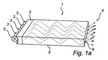
図1a及び図1bは、平らなプレーナ型導波路1を示しており、この導波路は、複数の光源3、例えばLEDからの光を受け取る入力側結合構造体2と、光を導波路1から出力して結合させる取り出し構造体4とを有している。入力側結合構造体2と取り出し構造体4との間では、光は、案内エッジ5によって導波路1内に保持される。案内エッジ5は、エッジのところ及び(又は)頂面及び(又は)底面のところの全反射(TIR)、レフレクタ又はPIRとレフレクタの組合せを利用するのが良い。 FIGS. 1 a and 1 b show a planar planar waveguide 1, which comprises an
導波路は、1種類、又は複数種類の誘電体の組合せから成るスラブで形成されるのが良い。適当な誘電体としては、種々の透明な材料、例えば、種々のガラス、ポリメチルメタクリレート(PMMA)等挙げられる。また、導波路は、導波路レフレクタにより少なくとも部分的に包囲された空気であっても良い。導波路の材料は、好ましくは、導波路とその周りの媒体との間のインタフェースが入力側結合構造体により提供される入射角の光に関して全反射のための条件を満足するように選択される。 The waveguide may be formed of a slab composed of one type or a combination of a plurality of types of dielectric materials. Suitable dielectrics include various transparent materials such as various glasses and polymethyl methacrylate (PMMA). The waveguide may be air that is at least partially surrounded by a waveguide reflector. The material of the waveguide is preferably selected so that the interface between the waveguide and the surrounding medium satisfies the conditions for total reflection with respect to the incident angle of light provided by the input coupling structure .
図1aでは、出力側構造体4は、光を通過させることができるようになった導波路のエッジ6により形成される。TIR導波路の場合、このことは、エッジ6が全反射のための条件を欠くようになっていることを意味している。例えば、エッジ6は、光を散乱させ又は拡散層を有する構造体を備えるのが良い。 In FIG. 1a, the output-side structure 4 is formed by an edge 6 of the waveguide that is allowed to pass light. In the case of a TIR waveguide, this means that the edge 6 lacks the condition for total reflection. For example, the edge 6 may comprise a structure that scatters light or has a diffusion layer.
図1bでは、取り出し構造体4は、光を案内エッジの1つに向かって、しかしながら、全反射のための条件をもはや満足しないような入射角で差し向けるようになった反射面7であり、光は、案内エッジ5を通過することになる。 In FIG. 1b, the extraction structure 4 is a reflecting surface 7 that is adapted to direct light towards one of the guiding edges, but at an angle of incidence that no longer satisfies the conditions for total reflection, The light will pass through the
本発明の一実施形態によれば、図1の取り出し構造体、例えば拡散層又は図1bの反射面は、非対称拡散層8,9を備えている。 According to one embodiment of the invention, the extraction structure of FIG. 1, for example the diffusion layer or the reflective surface of FIG. 1 b, comprises asymmetric diffusion layers 8, 9.
光が取り出し構造体を通って取り出しされる場合、非対称拡散層は、透明な層である。このような層は、種々の技術によって実現でき、このような技術としては、拡散箔を積層すること又は機械的な力を用いて表面を一方向に粗くすること、導波路が高温状態にある(それ故に、変形可能である)間にパターンをエンボス加工すること、レーザを用いて構造体を作製すること又はリソグラフデフィニションを行うことが挙げられるが、これらには限定されない。 When light is extracted through the extraction structure, the asymmetric diffusion layer is a transparent layer. Such a layer can be realized by various techniques, such as laminating diffusion foils or roughening the surface in one direction using mechanical force, and the waveguide is in a high temperature state. Examples include, but are not limited to, embossing the pattern during (and therefore can be deformed), making a structure using a laser, or performing lithographic definition.
光が取り出し構造体内で反射される場合(例えば、図1b)、非対称拡散層は、非対称拡散鏡、例えば陽極処理アルミニウム(アルマイト)のレフレクタであるのが良い。このようなレフレクタは、例えば、MIROという商標名でアラノッド・カンパニー(Alanod Company)によって提供されている。 If light is reflected within the extraction structure (eg, FIG. 1b), the asymmetric diffuser layer may be an asymmetric diffuser mirror, eg, an anodized aluminum (alumite) reflector. Such a reflector is provided, for example, by the Alanod Company under the trade name MIRO.
図2は、非対称拡散方式を示している。光線21が非対称ディフューザ22を通過すると、光は、第2の平面bよりも第1の平面Aのほうで一層拡散される。その結果、出射されるビーム23は、楕円形の断面24を有する。 FIG. 2 shows an asymmetric diffusion scheme. When the
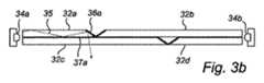
図3aは、主として2つのホルダ33a,33b相互間に吊り下げられた多くの透明なプレーナ型導波路32a〜32dにより構成された平べったい透明なランプの形態をしている照明器具31を斜視図で示している。ホルダ内には、この場合、ランバーティアンLED(図3b参照)の形態をした光源34a〜34bの1−Dアレイが収納されている。 FIG. 3a shows a
図3bを参照すると、光源アレイ34aのうちの1つからの光35は、導波路32aの1つの中に取り出され、導波路によって運ばれ、そして鏡36aでの反射後、鏡36a付近で導波路32aの底面37aを通って導波路2aから取り出しされる。光は、当然のことながら、同様に残りの導波路32b〜32dを通って案内される。上述の例では、4つの導波路32a〜32dが用いられている。当然のことながら、これよりも多い数の導波路を用いることができる。 Referring to FIG. 3b, light 35 from one of the
図4では、本発明の導波路の用途の第2の例が概略的に示されている。この場合、2つの照明器具41a,41bが、ここでは平らな(フラット型)テレビ受像機の形態をしたディスプレイ装置40内に組み込まれている。照明器具41a,41bの目的は、アンビエント照明をテレビ受像機周りに提供し、それによりユーザの視聴上の体感を向上させることにある。照明器具41a,41bの各々は、導波路42a,42b及び3つの側部発光型LED43a〜43c,44a〜44cを有しており、これらLEDは、好ましくは、赤色(R)、緑色(G)及び青色(B)LEDである。導波路の各々は、3つの案内エッジ45a〜45c,46a〜46c及び1つの透過性の抽出エッジ45d,46dを更に有している。これらアンビエント照明器具41a,41bの動作中、着色光源43a〜43c,44a〜44cからの光は、導波路42a,42b内に運ばれてこの中で混合され、抽出エッジ45d,46dを通って白色光として放出される。 FIG. 4 schematically shows a second example of the use of the waveguide of the present invention. In this case, two
当業者であれば、本発明は、上述の好ましい実施形態には何ら限定されることがないことがわかる。さらに、特許請求の範囲に記載された本発明の範囲内で多くの改造例及び変形例を想到できる。例えば、放出された光の空間一様性の向上を達成するためにマクロ構造と拡散面の組合せを有利に用いることができる。さらに、多くの数の且つ上述した色とは別の色の光源を用いることができる。特に、汎用照明用途に関し、演色評価数を向上させる第4又は更に第5の色、例えばアンバー(こはく色)又はシアン(青緑色)を追加することが有用な場合がある。案内エッジに加えて、導波路の頂面及び底面も又、反射方向が所与の入射方向において表面に当たる光線の入射位置につれて変化するよう構成されても良い。さらに、多層レフレクタをレフレクタとして用いることができる。このような多層レフレクタは、金属レフレクタよりも低い吸光度を有する状態で設計されるのが良い。 One skilled in the art will recognize that the present invention is not limited to the preferred embodiments described above. In addition, many modifications and variations are possible within the scope of the present invention as set forth in the claims. For example, a combination of macrostructures and diffusing surfaces can be advantageously used to achieve improved spatial uniformity of emitted light. In addition, a large number of light sources of different colors from those described above can be used. In particular, for general lighting applications, it may be useful to add a fourth or even fifth color that improves the color rendering index, such as amber (amber) or cyan (blue-green). In addition to the guiding edge, the top and bottom surfaces of the waveguide may also be configured such that the direction of reflection varies with the incident position of the light ray that strikes the surface in a given incident direction. Furthermore, a multilayer reflector can be used as the reflector. Such a multilayer reflector may be designed with a lower absorbance than the metal reflector.
Claims (11)
Translated fromJapaneseほぼ取り出し方向への前記導波路からの前記光の取り出しを可能にする取り出し構造体と、
前記光を前記取り出し構造体に向かう途中で反射することによって前記光を前記導波路内に封じ込める少なくとも1つの案内エッジとを有する導波路において、
前記取り出し構造体は、非対称拡散層を有する、
ことを特徴とする導波路。A waveguide for guiding light from at least one light source,
An extraction structure that allows extraction of the light from the waveguide in a substantially extraction direction;
In a waveguide having at least one guide edge that encloses the light in the waveguide by reflecting the light on its way to the extraction structure;
The extraction structure has an asymmetric diffusion layer;
A waveguide characterized by that.
請求項1記載の導波路。The diffusion layer diffuses light separately in two different planes that are substantially parallel to the output side direction.
The waveguide according to claim 1.
請求項1又は2記載の導波路。The waveguide guides light from a plurality of light sources and mixes the light in at least one mixing plane;
The waveguide according to claim 1 or 2.
請求項3記載の導波路。The diffusion layer diffuses light more in the mixing plane than in a plane perpendicular to the mixing plane;
The waveguide according to claim 3.
請求項1ないし4のいずれか1項に記載の導波路。The diffusion layer is a transparent diffusion layer,
The waveguide according to any one of claims 1 to 4.
請求項1ないし4のいずれか1項に記載の導波路。The diffusion layer is a diffusion mirror.
The waveguide according to any one of claims 1 to 4.
請求項1ないし6のいずれか1項に記載の導波路。The waveguide is a planar waveguide.
The waveguide according to any one of claims 1 to 6.
請求項1ないし7のいずれか1項に記載の導波路とを有する照明器具。At least one light source;
A lighting fixture comprising the waveguide according to any one of claims 1 to 7.
請求項8記載の照明器具。The lighting fixture has a plurality of light sources,
The lighting fixture according to claim 8.
請求項8又は9記載の照明器具。At least one of the light sources is at least one of a side-emitting LED and a Lambertian LED,
The lighting fixture according to claim 8 or 9.
Applications Claiming Priority (2)
| Application Number | Priority Date | Filing Date | Title |
|---|---|---|---|
| EP06116875 | 2006-07-10 | ||
| PCT/IB2007/052636WO2008007315A1 (en) | 2006-07-10 | 2007-07-05 | Waveguide with asymmetric outcoupling |
Publications (1)
| Publication Number | Publication Date |
|---|---|
| JP2009543155Atrue JP2009543155A (en) | 2009-12-03 |
Family
ID=38617966
Family Applications (1)
| Application Number | Title | Priority Date | Filing Date |
|---|---|---|---|
| JP2009519031APendingJP2009543155A (en) | 2006-07-10 | 2007-07-05 | Asymmetric extraction waveguide |
Country Status (5)
| Country | Link |
|---|---|
| US (1) | US20090257712A1 (en) |
| EP (1) | EP2041485A1 (en) |
| JP (1) | JP2009543155A (en) |
| CN (1) | CN101490467A (en) |
| WO (1) | WO2008007315A1 (en) |
Cited By (2)
| Publication number | Priority date | Publication date | Assignee | Title |
|---|---|---|---|---|
| JP2012252952A (en)* | 2011-06-06 | 2012-12-20 | Minebea Co Ltd | Light emitting device |
| JP2020518941A (en)* | 2016-12-02 | 2020-06-25 | アセンシア・ディアベティス・ケア・ホールディングス・アーゲー | System, method and apparatus for illuminating the edge portion of the surface of an electronic device display lens |
Families Citing this family (20)
| Publication number | Priority date | Publication date | Assignee | Title |
|---|---|---|---|---|
| CA2726151C (en) | 2008-05-30 | 2016-11-22 | Koninklijke Philips Electronics N.V. | Round illumination device |
| JP5283005B2 (en)* | 2010-06-15 | 2013-09-04 | シーシーエス株式会社 | Lighting device |
| EP2400225B1 (en)* | 2010-06-26 | 2018-11-14 | Electrolux Home Products Corporation N.V. | Oven muffle comprising a lighting system |
| CN102313999A (en)* | 2010-07-07 | 2012-01-11 | 北京中视中科光电技术有限公司 | Device for weakening laser speckle |
| EP2439564A1 (en)* | 2010-10-06 | 2012-04-11 | Koninklijke Philips Electronics N.V. | Light-emitting device for emitting diffuse light |
| US8573823B2 (en)* | 2011-08-08 | 2013-11-05 | Quarkstar Llc | Solid-state luminaire |
| US9081125B2 (en) | 2011-08-08 | 2015-07-14 | Quarkstar Llc | Illumination devices including multiple light emitting elements |
| CN103858244B (en)* | 2011-08-08 | 2018-08-10 | 夸克星有限责任公司 | Lighting device comprising a plurality of light emitting elements |
| EP2895794B1 (en)* | 2012-09-13 | 2018-06-27 | Quarkstar LLC | Illumination systems providing direct and indirect illumination |
| WO2014043369A2 (en) | 2012-09-13 | 2014-03-20 | Quarkstar Llc | Devices for workspace illumination |
| KR20150059751A (en)* | 2012-09-20 | 2015-06-02 | 톰슨 라이센싱 | Panel illumination system |
| US9206956B2 (en) | 2013-02-08 | 2015-12-08 | Quarkstar Llc | Illumination device providing direct and indirect illumination |
| WO2014172571A2 (en) | 2013-04-19 | 2014-10-23 | Quarkstar Llc | Illumination devices with adjustable optical elements |
| EP3422059B1 (en) | 2013-07-18 | 2025-09-03 | Quarkstar LLC | Illumination device in which source light injection is non-parallel to device's optical axis |
| CN105723150B (en) | 2013-09-17 | 2019-02-22 | 夸克星有限责任公司 | Light guide lighting fixture with light divergence modifier |
| GB201412752D0 (en) | 2014-07-17 | 2014-09-03 | Nicoventures Holdings Ltd | Electronic vapour provision system |
| US10468566B2 (en) | 2017-04-10 | 2019-11-05 | Ideal Industries Lighting Llc | Hybrid lens for controlled light distribution |
| KR102843635B1 (en)* | 2019-07-03 | 2025-08-07 | 엘지이노텍 주식회사 | Lighting module, lighting apparatus and lamp |
| DE102020204577A1 (en) | 2020-04-09 | 2021-10-14 | Volkswagen Aktiengesellschaft | Light guide arrangement, edge decoupling element and lighting system for a vehicle |
| CN119781111B (en)* | 2025-03-13 | 2025-05-30 | 苏州理湃科技有限公司 | An optical waveguide device |
Family Cites Families (12)
| Publication number | Priority date | Publication date | Assignee | Title |
|---|---|---|---|---|
| US6002829A (en)* | 1992-03-23 | 1999-12-14 | Minnesota Mining And Manufacturing Company | Luminaire device |
| ES2178663T3 (en)* | 1994-03-25 | 2003-01-01 | Novartis Ag | LIGHT DIFFUSER AND PROCESS FOR THE MANUFACTURE OF A LIGHT DIFFUSER. |
| US6712481B2 (en)* | 1995-06-27 | 2004-03-30 | Solid State Opto Limited | Light emitting panel assemblies |
| US5999281A (en)* | 1997-02-28 | 1999-12-07 | Polaroid Corporation | Holographic projection screen combining an elliptical holographic diffuser and a cylindrical light-collimator |
| EP1082638A4 (en)* | 1999-03-24 | 2001-05-30 | Lg Chemical Ltd | A backlight system |
| US6909480B2 (en)* | 2000-10-19 | 2005-06-21 | Daicel Chemical Industries, Ltd. | Anisotropic scattering sheet and its use |
| ATE521002T1 (en)* | 2002-04-25 | 2011-09-15 | Koninkl Philips Electronics Nv | COMPACT LIGHTING SYSTEM AND DISPLAY DEVICE |
| US7180672B2 (en)* | 2002-05-20 | 2007-02-20 | General Electric Company | Optical substrate and method of making |
| US7052168B2 (en)* | 2003-12-17 | 2006-05-30 | 3M Innovative Properties Company | Illumination device |
| US7431489B2 (en)* | 2004-11-17 | 2008-10-07 | Fusion Optix Inc. | Enhanced light fixture |
| WO2006055873A2 (en)* | 2004-11-17 | 2006-05-26 | Fusion Optix, Inc. | Enhanced electroluminescent sign |
| US7430358B2 (en)* | 2005-04-20 | 2008-09-30 | Wavefront Technology, Inc. | Elliptical diffusers used in displays |
- 2007
- 2007-07-05JPJP2009519031Apatent/JP2009543155A/enactivePending
- 2007-07-05WOPCT/IB2007/052636patent/WO2008007315A1/enactiveApplication Filing
- 2007-07-05USUS12/306,743patent/US20090257712A1/ennot_activeAbandoned
- 2007-07-05CNCNA2007800260863Apatent/CN101490467A/enactivePending
- 2007-07-05EPEP07789891Apatent/EP2041485A1/ennot_activeWithdrawn
Cited By (3)
| Publication number | Priority date | Publication date | Assignee | Title |
|---|---|---|---|---|
| JP2012252952A (en)* | 2011-06-06 | 2012-12-20 | Minebea Co Ltd | Light emitting device |
| JP2020518941A (en)* | 2016-12-02 | 2020-06-25 | アセンシア・ディアベティス・ケア・ホールディングス・アーゲー | System, method and apparatus for illuminating the edge portion of the surface of an electronic device display lens |
| JP7042825B2 (en) | 2016-12-02 | 2022-03-28 | アセンシア・ディアベティス・ケア・ホールディングス・アーゲー | Electronic devices Systems, methods, and devices for illuminating the edges of a display lens surface. |
Also Published As
| Publication number | Publication date |
|---|---|
| EP2041485A1 (en) | 2009-04-01 |
| US20090257712A1 (en) | 2009-10-15 |
| WO2008007315A1 (en) | 2008-01-17 |
| CN101490467A (en) | 2009-07-22 |
Similar Documents
| Publication | Publication Date | Title |
|---|---|---|
| JP2009543155A (en) | Asymmetric extraction waveguide | |
| CN108027130B (en) | Large area light source and large area luminaire | |
| CN102472860B (en) | Free form lighting module | |
| US9291767B2 (en) | Free form lighting module | |
| US10473847B2 (en) | Illumination device having a light guide with leaky side surfaces | |
| US20170052305A1 (en) | Light Guide Illumination Device With Light Divergence Modifier | |
| JP5608752B2 (en) | Light emitting device | |
| CN102037273B (en) | Luminaire kits and methods | |
| JP2008515138A (en) | Lighting system | |
| US10551547B2 (en) | Troffer luminaire | |
| US20110199780A1 (en) | Illumination device configured to mix light from a first and a second light emitting device | |
| JP2018510468A (en) | Illumination system using light guide and illumination method | |
| US20140092628A1 (en) | Illumination device | |
| JP4668131B2 (en) | Light guide plate and lighting device | |
| JP2012515425A (en) | Light block | |
| CN100587566C (en) | Plane light source device with secondary light guide | |
| TW201445087A (en) | Light guide device and illumination apparatus |