JP2009540962A - Ablation and visualization equipment - Google Patents
Ablation and visualization equipmentDownload PDFInfo
- Publication number
- JP2009540962A JP2009540962AJP2009516723AJP2009516723AJP2009540962AJP 2009540962 AJP2009540962 AJP 2009540962AJP 2009516723 AJP2009516723 AJP 2009516723AJP 2009516723 AJP2009516723 AJP 2009516723AJP 2009540962 AJP2009540962 AJP 2009540962A
- Authority
- JP
- Japan
- Prior art keywords
- scope
- shaft
- ablation
- coupled
- distal end
- Prior art date
- Legal status (The legal status is an assumption and is not a legal conclusion. Google has not performed a legal analysis and makes no representation as to the accuracy of the status listed.)
- Pending
Links
- 238000002679ablationMethods0.000titleclaimsabstractdescription128
- 238000012800visualizationMethods0.000titleclaimsabstractdescription21
- 230000003287optical effectEffects0.000claimsabstractdescription12
- 239000000835fiberSubstances0.000claimsabstractdescription5
- 210000001519tissueAnatomy0.000description41
- 238000000034methodMethods0.000description24
- 230000003902lesionEffects0.000description22
- 238000011282treatmentMethods0.000description21
- 210000003492pulmonary veinAnatomy0.000description19
- 210000002216heartAnatomy0.000description12
- 238000002604ultrasonographyMethods0.000description12
- 206010003658Atrial FibrillationDiseases0.000description8
- 238000002955isolationMethods0.000description7
- 230000001746atrial effectEffects0.000description6
- 230000006378damageEffects0.000description6
- 210000004165myocardiumAnatomy0.000description6
- 208000020128Mitral stenosisDiseases0.000description5
- 210000003484anatomyAnatomy0.000description5
- 230000008901benefitEffects0.000description5
- 230000008859changeEffects0.000description5
- 208000006887mitral valve stenosisDiseases0.000description5
- 208000002847Surgical WoundDiseases0.000description4
- 210000004115mitral valveAnatomy0.000description4
- 208000027418Wounds and injuryDiseases0.000description3
- 230000000694effectsEffects0.000description3
- 208000014674injuryDiseases0.000description3
- 210000005246left atriumAnatomy0.000description3
- 230000007246mechanismEffects0.000description3
- 238000001356surgical procedureMethods0.000description3
- 240000008042Zea maysSpecies0.000description2
- 235000016383Zea mays subsp huehuetenangensisNutrition0.000description2
- 235000002017Zea mays subsp maysNutrition0.000description2
- 238000010009beatingMethods0.000description2
- 239000008280bloodSubstances0.000description2
- 210000004369bloodAnatomy0.000description2
- 238000013153catheter ablationMethods0.000description2
- 210000003238esophagusAnatomy0.000description2
- 238000010438heat treatmentMethods0.000description2
- 238000000608laser ablationMethods0.000description2
- 235000009973maizeNutrition0.000description2
- 210000000056organAnatomy0.000description2
- 210000005245right atriumAnatomy0.000description2
- 230000007480spreadingEffects0.000description2
- 230000000007visual effectEffects0.000description2
- 208000006687Esophageal FistulaDiseases0.000description1
- 241000703391Lipovnik virusSpecies0.000description1
- 206010065835Oesophageal fistulaDiseases0.000description1
- 238000010521absorption reactionMethods0.000description1
- 239000003416antiarrhythmic agentSubstances0.000description1
- 210000000709aortaAnatomy0.000description1
- 238000013459approachMethods0.000description1
- 230000002763arrhythmic effectEffects0.000description1
- 210000001367arteryAnatomy0.000description1
- 230000009286beneficial effectEffects0.000description1
- 230000002612cardiopulmonary effectEffects0.000description1
- 210000000038chestAnatomy0.000description1
- 239000012141concentrateSubstances0.000description1
- 238000001816coolingMethods0.000description1
- 230000008878couplingEffects0.000description1
- 238000010168coupling processMethods0.000description1
- 238000005859coupling reactionMethods0.000description1
- 238000013480data collectionMethods0.000description1
- 239000012530fluidSubstances0.000description1
- 210000005003heart tissueAnatomy0.000description1
- 230000006872improvementEffects0.000description1
- 230000000977initiatory effectEffects0.000description1
- 210000005248left atrial appendageAnatomy0.000description1
- 210000004072lungAnatomy0.000description1
- 238000004519manufacturing processMethods0.000description1
- 238000013507mappingMethods0.000description1
- 239000000463materialSubstances0.000description1
- 238000002324minimally invasive surgeryMethods0.000description1
- 239000013307optical fiberSubstances0.000description1
- 230000035515penetrationEffects0.000description1
- 238000003672processing methodMethods0.000description1
- 238000007674radiofrequency ablationMethods0.000description1
- 238000011084recoveryMethods0.000description1
- 210000005247right atrial appendageAnatomy0.000description1
- 231100000241scarToxicity0.000description1
- 210000000115thoracic cavityAnatomy0.000description1
- 210000003462veinAnatomy0.000description1
- 210000001631vena cava inferiorAnatomy0.000description1
- 210000002620vena cava superiorAnatomy0.000description1
Images


Classifications
- A—HUMAN NECESSITIES
- A61—MEDICAL OR VETERINARY SCIENCE; HYGIENE
- A61B—DIAGNOSIS; SURGERY; IDENTIFICATION
- A61B1/00—Instruments for performing medical examinations of the interior of cavities or tubes of the body by visual or photographical inspection, e.g. endoscopes; Illuminating arrangements therefor
- A61B1/005—Flexible endoscopes
- A—HUMAN NECESSITIES
- A61—MEDICAL OR VETERINARY SCIENCE; HYGIENE
- A61B—DIAGNOSIS; SURGERY; IDENTIFICATION
- A61B1/00—Instruments for performing medical examinations of the interior of cavities or tubes of the body by visual or photographical inspection, e.g. endoscopes; Illuminating arrangements therefor
- A61B1/00064—Constructional details of the endoscope body
- A61B1/00071—Insertion part of the endoscope body
- A61B1/0008—Insertion part of the endoscope body characterised by distal tip features
- A61B1/00087—Tools
- A—HUMAN NECESSITIES
- A61—MEDICAL OR VETERINARY SCIENCE; HYGIENE
- A61B—DIAGNOSIS; SURGERY; IDENTIFICATION
- A61B1/00—Instruments for performing medical examinations of the interior of cavities or tubes of the body by visual or photographical inspection, e.g. endoscopes; Illuminating arrangements therefor
- A61B1/00131—Accessories for endoscopes
- A61B1/0014—Fastening element for attaching accessories to the outside of an endoscope, e.g. clips, clamps or bands
- A—HUMAN NECESSITIES
- A61—MEDICAL OR VETERINARY SCIENCE; HYGIENE
- A61B—DIAGNOSIS; SURGERY; IDENTIFICATION
- A61B90/00—Instruments, implements or accessories specially adapted for surgery or diagnosis and not covered by any of the groups A61B1/00 - A61B50/00, e.g. for luxation treatment or for protecting wound edges
- A61B90/36—Image-producing devices or illumination devices not otherwise provided for
- A—HUMAN NECESSITIES
- A61—MEDICAL OR VETERINARY SCIENCE; HYGIENE
- A61B—DIAGNOSIS; SURGERY; IDENTIFICATION
- A61B18/00—Surgical instruments, devices or methods for transferring non-mechanical forms of energy to or from the body
- A61B18/04—Surgical instruments, devices or methods for transferring non-mechanical forms of energy to or from the body by heating
- A61B18/12—Surgical instruments, devices or methods for transferring non-mechanical forms of energy to or from the body by heating by passing a current through the tissue to be heated, e.g. high-frequency current
- A61B18/14—Probes or electrodes therefor
- A—HUMAN NECESSITIES
- A61—MEDICAL OR VETERINARY SCIENCE; HYGIENE
- A61B—DIAGNOSIS; SURGERY; IDENTIFICATION
- A61B18/00—Surgical instruments, devices or methods for transferring non-mechanical forms of energy to or from the body
- A61B18/18—Surgical instruments, devices or methods for transferring non-mechanical forms of energy to or from the body by applying electromagnetic radiation, e.g. microwaves
- A61B18/20—Surgical instruments, devices or methods for transferring non-mechanical forms of energy to or from the body by applying electromagnetic radiation, e.g. microwaves using laser
- A61B18/22—Surgical instruments, devices or methods for transferring non-mechanical forms of energy to or from the body by applying electromagnetic radiation, e.g. microwaves using laser the beam being directed along or through a flexible conduit, e.g. an optical fibre; Couplings or hand-pieces therefor
- A61B18/24—Surgical instruments, devices or methods for transferring non-mechanical forms of energy to or from the body by applying electromagnetic radiation, e.g. microwaves using laser the beam being directed along or through a flexible conduit, e.g. an optical fibre; Couplings or hand-pieces therefor with a catheter
- A—HUMAN NECESSITIES
- A61—MEDICAL OR VETERINARY SCIENCE; HYGIENE
- A61B—DIAGNOSIS; SURGERY; IDENTIFICATION
- A61B17/00—Surgical instruments, devices or methods
- A61B17/00234—Surgical instruments, devices or methods for minimally invasive surgery
- A61B2017/00238—Type of minimally invasive operation
- A61B2017/00243—Type of minimally invasive operation cardiac
- A—HUMAN NECESSITIES
- A61—MEDICAL OR VETERINARY SCIENCE; HYGIENE
- A61B—DIAGNOSIS; SURGERY; IDENTIFICATION
- A61B17/00—Surgical instruments, devices or methods
- A61B17/00234—Surgical instruments, devices or methods for minimally invasive surgery
- A61B2017/00292—Surgical instruments, devices or methods for minimally invasive surgery mounted on or guided by flexible, e.g. catheter-like, means
- A61B2017/00296—Surgical instruments, devices or methods for minimally invasive surgery mounted on or guided by flexible, e.g. catheter-like, means mounted on an endoscope
- A—HUMAN NECESSITIES
- A61—MEDICAL OR VETERINARY SCIENCE; HYGIENE
- A61B—DIAGNOSIS; SURGERY; IDENTIFICATION
- A61B18/00—Surgical instruments, devices or methods for transferring non-mechanical forms of energy to or from the body
- A61B18/04—Surgical instruments, devices or methods for transferring non-mechanical forms of energy to or from the body by heating
- A61B18/12—Surgical instruments, devices or methods for transferring non-mechanical forms of energy to or from the body by heating by passing a current through the tissue to be heated, e.g. high-frequency current
- A61B18/14—Probes or electrodes therefor
- A61B2018/1495—Electrodes being detachable from a support structure
- A—HUMAN NECESSITIES
- A61—MEDICAL OR VETERINARY SCIENCE; HYGIENE
- A61B—DIAGNOSIS; SURGERY; IDENTIFICATION
- A61B90/00—Instruments, implements or accessories specially adapted for surgery or diagnosis and not covered by any of the groups A61B1/00 - A61B50/00, e.g. for luxation treatment or for protecting wound edges
- A61B90/30—Devices for illuminating a surgical field, the devices having an interrelation with other surgical devices or with a surgical procedure
- A61B2090/306—Devices for illuminating a surgical field, the devices having an interrelation with other surgical devices or with a surgical procedure using optical fibres
- A—HUMAN NECESSITIES
- A61—MEDICAL OR VETERINARY SCIENCE; HYGIENE
- A61B—DIAGNOSIS; SURGERY; IDENTIFICATION
- A61B90/00—Instruments, implements or accessories specially adapted for surgery or diagnosis and not covered by any of the groups A61B1/00 - A61B50/00, e.g. for luxation treatment or for protecting wound edges
- A61B90/36—Image-producing devices or illumination devices not otherwise provided for
- A61B90/361—Image-producing devices, e.g. surgical cameras
- A61B2090/3614—Image-producing devices, e.g. surgical cameras using optical fibre
- A—HUMAN NECESSITIES
- A61—MEDICAL OR VETERINARY SCIENCE; HYGIENE
- A61N—ELECTROTHERAPY; MAGNETOTHERAPY; RADIATION THERAPY; ULTRASOUND THERAPY
- A61N7/00—Ultrasound therapy
- A61N7/02—Localised ultrasound hyperthermia
- A61N7/022—Localised ultrasound hyperthermia intracavitary
Landscapes
- Health & Medical Sciences (AREA)
- Life Sciences & Earth Sciences (AREA)
- Surgery (AREA)
- General Health & Medical Sciences (AREA)
- Public Health (AREA)
- Veterinary Medicine (AREA)
- Pathology (AREA)
- Nuclear Medicine, Radiotherapy & Molecular Imaging (AREA)
- Animal Behavior & Ethology (AREA)
- Engineering & Computer Science (AREA)
- Biomedical Technology (AREA)
- Heart & Thoracic Surgery (AREA)
- Medical Informatics (AREA)
- Molecular Biology (AREA)
- Biophysics (AREA)
- Physics & Mathematics (AREA)
- Radiology & Medical Imaging (AREA)
- Optics & Photonics (AREA)
- Oral & Maxillofacial Surgery (AREA)
- Surgical Instruments (AREA)
- Endoscopes (AREA)
- Laser Surgery Devices (AREA)
Abstract
Translated fromJapaneseDescription
Translated fromJapanese(関連出願の相互参照)
本発明は、2006年6月23日出願の米国特許仮出願第60/815,880号(’880出願)の恩典を主張する。本出願はまた、現在係属中の2006年12月21日出願の米国特許非仮出願第11/642,923号(’923出願)の優先権も主張する。’880出願と’923出願はともに、本明細書で充分に説明した場合と同じように、参照によって本明細書の一部とする。(Cross-reference of related applications)
The present invention claims the benefit of US Provisional Application No. 60 / 815,880, filed June 23, 2006 (the '880 application). This application also claims the priority of currently pending US patent non-provisional application No. 11 / 642,923 (the '923 application), filed December 21, 2006. Both the '880 application and the' 923 application are hereby incorporated by reference as if fully set forth herein.
本出願は、2006年6月23日に全て出願された米国仮特許出願第60/815,852、米国仮特許出願第60/815,853号、米国仮特許出願第60/815,881号、および仮特許出願第60/815,882号に関連している。以上の出願の全てを、それらを本明細書で充分に説明した場合と同じように、参照によって本明細書の一部とする。 This application is a U.S. provisional patent application 60 / 815,852, U.S. provisional patent application 60 / 815,853, U.S. provisional patent application 60 / 815,881, filed June 23, 2006, And provisional patent application 60 / 815,882. All of the above applications are hereby incorporated by reference as if fully set forth herein.
本発明は、心房細動の治療に関する。特に、本発明は、心外膜マッピング中およびアブレーション処置中に標的組織を可視化する装置および方法に関する。 The present invention relates to the treatment of atrial fibrillation. In particular, the present invention relates to an apparatus and method for visualizing a target tissue during epicardial mapping and ablation procedures.
心房細動は、心筋(心筋層)における電気的活動の乱れから生じることがよく知られている。心房細動の治療のために、外科的メイズ手術が開発されている。これは、予め選択されたパターンで心房心筋に一連の外科的切開部を作り出して、瘢痕組織によって境界を形成して生存組織による伝導性ルートを作り出すことを伴う。 It is well known that atrial fibrillation results from disturbance of electrical activity in the myocardium (myocardium). Surgical maze surgery has been developed for the treatment of atrial fibrillation. This entails creating a series of surgical incisions in the atrial myocardium in a preselected pattern, bounded by scar tissue and creating a conductive route through living tissue.
メイズ手術の外科的切開の代替方法として、心臓の経壁アブレーションを使用してもよい。このようなアブレーションは、動脈または静脈を通して導入した血管内装置(カテーテルなど)を使用することによって心室の中から行う場合や(心内膜アブレーション)、患者の胸部の中に導入した装置を使用することによって心臓の外側から行う場合がある(心外膜アブレーション)。極低温アブレーション、高周波(RF)アブレーション、レーザ・アブレーション、超音波アブレーション、およびマイクロ波アブレーションを始め、これらに限定されることなく様々なアブレーション技法を使用することができる。アブレーション装置を使用して、長い経壁損傷部、即ち心筋の充分な厚みにわたって延在する損傷部を作り出して電気伝導を阻止し、これによって心房心筋内に伝導性ルートの境界を形成している。外科的切開に代わって経壁アブレーションを使用することの最大の利点はおそらく、最初に心肺バイパス(CPB)を確立せずにアブレーション処置を行うことが可能となることである。 As an alternative to a surgical incision in maize surgery, transmural ablation of the heart may be used. Such ablation may be performed from inside the ventricle by using an intravascular device (such as a catheter) introduced through an artery or vein (endocardial ablation) or using a device introduced into the patient's chest. Sometimes it is done from outside the heart (epicardial ablation). A variety of ablation techniques can be used including, but not limited to, cryogenic ablation, radio frequency (RF) ablation, laser ablation, ultrasonic ablation, and microwave ablation. Using an ablation device to create a long transmural lesion, i.e., a lesion that extends through the full thickness of the myocardium to block electrical conduction, thereby forming a conductive route boundary within the atrial myocardium . Perhaps the greatest advantage of using transmural ablation instead of a surgical incision is that it is possible to perform an ablation procedure without first establishing a cardiopulmonary bypass (CPB).
アブレーションを使用する場合も、外科的切開を使用する場合も、メイズ手術およびその変形手術を行う際には、肺静脈を周囲の心筋から隔離する経壁切開部または経壁損傷部を設けることが最も有効であると一般に考えられている。肺静脈は、心臓の後部側の左心房壁と接合して、肺を心臓の左心房に繋げている。このような処置は、抗不整脈薬の投与なしで57%から70%の成功をもたらすことが分かっている。しかしこれらの処置は、損傷部の回復、不整脈の非肺静脈の病巣、またはさらなる組織改良の必要性を原因とする20%から60%の再発率とも関連している。 Whether using ablation or a surgical incision, a transmural incision or transmural lesion that isolates the pulmonary vein from the surrounding myocardium may be provided when performing maize and its deformed surgery. It is generally considered the most effective. The pulmonary vein joins the left atrial wall on the posterior side of the heart to connect the lung to the left atrium of the heart. Such treatment has been found to provide 57% to 70% success without the administration of antiarrhythmic drugs. However, these treatments are also associated with a recurrence rate of 20% to 60% due to injury recovery, arrhythmic non-pulmonary vein lesions, or the need for further tissue improvement.
過去の外科的アプローチとカテーテルに基づいたアプローチとによって、完全なブロックが達成された際には、左心房(LA)の直線的な損傷部が心房細動の治療で功を奏することが証明されている。このような技法の一つに、僧帽弁狭部における直線的なアブレーションがあり、これは、側方僧帽弁輪から左下肺静脈(LIPV)口に延在するものとして定義される。研究により、僧帽弁狭部のカテーテル・アブレーションと肺静脈(PV)隔離との組み合わせが、確実に明らかな伝導ブロックを形成し、この組み合わせが発作性心房細動に対する高い治癒率に関係していることが示されている。 Past surgical and catheter-based approaches have proven that left atrial (LA) linear lesions are successful in treating atrial fibrillation when complete block is achieved. ing. One such technique is linear ablation at the mitral valve narrow, which is defined as extending from the lateral mitral valve annulus to the left lower pulmonary vein (LIPV) port. Studies have shown that the combination of mitral stenosis catheter ablation and pulmonary vein (PV) isolation reliably forms a clear conduction block that is associated with a high cure rate for paroxysmal atrial fibrillation It has been shown that
これらの位置に正確な損傷部を作り出すことは、いくつかの理由で、心内膜アブレーションを行う医師に対して大きな障害を提示している。第一に、メイズ手術において作り出される損傷部の多くは、右心房の中から作り出すことが可能であるが、肺静脈の損傷部は左心房内で作り出さねばならず、別個の心房アクセス・ポイントまたは右心房からの中隔横断穿刺のいずれかが必要になる。第二に、細長い軟性の血管内アブレーション装置は、肺静脈損傷部を形成するのに必要な複雑な構造形状の中に入れることが困難である。また、アブレーション装置を、鼓動している心臓の壁に対して適切に位置付けて維持しておくことも困難である。さらに、心臓内の生体構造および血管内装置の可視化がしばしば不十分であって、血管内装置の正確な位置を知ることが困難なことがあり、これによって損傷部の位置を誤ってしまう可能性がある。 Creating precise lesions at these locations presents a major obstacle for physicians performing endocardial ablation for several reasons. First, many of the injuries created in the Maze procedure can be created from within the right atrium, while pulmonary vein injuries must be created in the left atrium and can be created in a separate atrial access point or Either a transseptal puncture from the right atrium is required. Second, elongate flexible endovascular ablation devices are difficult to put into the complex structural shapes necessary to form pulmonary vein lesions. It is also difficult to keep the ablation device properly positioned relative to the beating heart wall. In addition, visualization of anatomy and intravascular devices in the heart is often inadequate and it can be difficult to know the exact location of the intravascular device, which can lead to misplaced lesions. There is.
心房細動の治療のための経壁損傷部を作り出すのに有用な心外膜アブレーション装置および方法が、Vaskaらの米国特許第7,052,493号(「Vaska」)およびSliwaらの米国特許第6,971,394号(「Sliwa」)に記載されており、これらの両方を、本明細書で充分に説明した場合と同じように、参照によって明確に本明細書の一部とする。Sliwaは、胸部切開によって、次いで心膜貫通によってアブレーション装置を配置することによって、肺静脈に隣接した心臓壁内に経壁損傷部を形成して、アブレーション装置が心臓の心外膜面と接触するように配設されるようにする方法について述べている。このアブレーション装置は、カテーテルの作動端部の付近に、留め部、分岐部、または切欠きなどの位置決め装置であって、カテーテルの作動端部を肺静脈に隣接して位置付けるように、1つまたは複数の肺静脈または近傍の他の解剖学的構造物、(例えば心膜翻転部位、下大静脈、上大静脈、大動脈、左心耳、または右心耳)と係合するように構成された装置を含む。 Epicardial ablation devices and methods useful for creating transmural lesions for the treatment of atrial fibrillation are disclosed in Vaska et al. US Pat. No. 7,052,493 (“Vaska”) and Sliwa et al. No. 6,971,394 (“Sliwa”), both of which are hereby expressly incorporated by reference, as if fully described herein. Sliwa forms a transmural lesion in the heart wall adjacent to the pulmonary vein by placing the ablation device by thoracic incision and then by pericardial penetration so that the ablation device contacts the epicardial surface of the heart The method of making it arrange | positioned is described. The ablation device is a positioning device, such as a clasp, bifurcation, or notch, in the vicinity of the working end of the catheter, one or more so as to position the working end of the catheter adjacent to the pulmonary vein. A device configured to engage multiple pulmonary veins or other nearby anatomical structures (eg, pericardial inversion sites, inferior vena cava, superior vena cava, aorta, left atrial appendage, or right atrial appendage) including.
心外膜面上でアブレーション素子を正確に配置することが、PV隔離と僧帽弁狭部のアブレーションとの有効性にとって極めて重要である。心臓以外の組織の解剖学的関係も極めて重要な考慮事項である。例えば食道は、後部左心房の近くにあることから、アブレーション処置中の食道の損傷を防止するように細心の注意を払わなければならない。これは心房細動に対するカテーテル・アブレーションに後続した合併症として心房食道瘻が報告されていることによる。しかし、非可視の位置決め装置に頼るには、極めて高度な医師のスキルおよび経験が必要であり、このような精確な配置の妨げとなる場合がある。 Accurate placement of the ablation element on the epicardial surface is critical to the effectiveness of PV isolation and mitral stenosis. Anatomical relationships of tissues other than the heart are also an important consideration. For example, because the esophagus is near the posterior left atrium, great care must be taken to prevent damage to the esophagus during the ablation procedure. This is because atrial esophageal fistula has been reported as a complication following catheter ablation for atrial fibrillation. However, reliance on invisible positioning devices requires extremely sophisticated physician skills and experience and may hinder such accurate placement.
したがって、アブレーション処置においてアブレーション装置の正確な配置を確認するために必要な心臓の解剖学的特徴を医師が直接見ることを可能にする装置を提供することが望ましい。 Accordingly, it would be desirable to provide a device that allows a physician to directly view the anatomical features of the heart necessary to confirm the correct placement of the ablation device in an ablation procedure.
また、アブレーション装置とアブレーション対象組織とに対する他の組織および器官の関係を医師が視覚的に検証することを可能にする装置を提供することも望ましい。 It would also be desirable to provide a device that allows a physician to visually verify the relationship of other tissues and organs to the ablation device and the tissue to be ablated.
本発明の第1実施形態によると、組織をアブレーションする装置は、遠位端部を有するシャフトと、シャフトの遠位端部に結合された少なくとも1つのアブレーション素子と、シャフトに遠位端部に近接して結合されたスコープであって、少なくとも1つの画像収集用アパチャを含むスコープとを備える。スコープは光ファイバ内視鏡、赤外線センサ、または超音波センサであってもよく、これを任意で、画像収集用アパチャを通してスコープによって収集された画像を視覚的に表示するように構成された出力装置に結合してもよい。少なくとも1つの光学素子を少なくとも1つの画像収集用アパチャの上方に位置付けてもよい。本発明の一部の実施形態では、スコープは、複数の画像収集用アパチャを含んでおり、そのうちの1つまたは複数が移動可能であってもよい。 According to a first embodiment of the present invention, an apparatus for ablating tissue includes a shaft having a distal end, at least one ablation element coupled to the distal end of the shaft, and a shaft at the distal end. A closely coupled scope including at least one image collection aperture. The scope may be a fiber optic endoscope, an infrared sensor, or an ultrasonic sensor, optionally with an output device configured to visually display an image collected by the scope through an image collection aperture May be combined. At least one optical element may be positioned above the at least one image collection aperture. In some embodiments of the invention, the scope includes a plurality of image collection apertures, one or more of which may be movable.
スコープを、少なくとも1つのアブレーション素子に対して側方に、または少なくとも1つのアブレーション素子が位置する平面と実質的に平行であり、かつその平面から離隔された平面内に位置付けてもよい。さらに、少なくとも1つのアパチャを少なくとも1つのアブレーション素子に対して遠位または近位に位置付けた状態で、スコープを位置付けてもよく、またスコープを、その視野が少なくとも1つのアブレーション素子の少なくとも一部分を含むように位置付けてもよい。任意で、スコープをシャフトにスライド可能または回転可能に結合してもよい。代替方法として、スコープをシャフトに一体化してもよい。 The scope may be positioned laterally to the at least one ablation element or in a plane that is substantially parallel to and spaced from the plane in which the at least one ablation element is located. Further, the scope may be positioned with the at least one aperture positioned distally or proximally relative to the at least one ablation element, and the scope includes a field of view including at least a portion of the at least one ablation element. You may position as follows. Optionally, the scope may be slidably or rotatably coupled to the shaft. As an alternative, the scope may be integrated into the shaft.
実質的に透明であってもよいキャップを、シャフトの遠位端部に結合してもよく、任意で取り外し可能に結合してもよく、スコープを、そのキャップを介してシャフトに結合してもよく、また任意で取り外し可能に結合してもよい。レンズまたはフィルタなど、少なくとも1つの光学素子をキャップの中に一体化してもよい。 A cap, which may be substantially transparent, may be coupled to the distal end of the shaft, optionally removably coupled, and the scope may be coupled to the shaft via the cap. Well, and optionally removably coupled. At least one optical element, such as a lens or filter, may be integrated into the cap.
本発明の他の実施形態によると、アブレーションおよび可視化装置は、遠位端部と近位端部を有するシャフトと、シャフトの遠位端部上に位置する少なくとも2つのアブレーション素子と、シャフトの遠位端部に結合されたスコープであって旋回アセンブリを介して移動可能であってもよい画像収集用アパチャを少なくとも1つ含むスコープとを含む。任意で、装置は、スコープの視野を変更するための、画像収集用アパチャの上に位置付けられた光学素子を含む。光学素子はレンズまたはフィルタであってもよい。スコープをシャフトの遠位端部と一体化してよく、シャフトの遠端部に直接結合してよく、あるいはシャフトの遠位端部に結合された実質的に透明なキャップに結合してもよい。 According to another embodiment of the present invention, an ablation and visualization device includes a shaft having a distal end and a proximal end, at least two ablation elements located on the distal end of the shaft, and a distal end of the shaft. A scope coupled to the distal end and including at least one image collection aperture that may be movable through a pivot assembly. Optionally, the apparatus includes an optical element positioned over the image collection aperture for changing the scope's field of view. The optical element may be a lens or a filter. The scope may be integral with the distal end of the shaft, may be directly coupled to the distal end of the shaft, or may be coupled to a substantially transparent cap coupled to the distal end of the shaft.
以下の記述および請求項を読み、添付の図面を検討することにより、本発明の上述および他の態様、特徴、詳細、有用性、および利点が明らかとなろう。 The foregoing and other aspects, features, details, utilities, and advantages of the present invention will become apparent upon reading the following description and claims, and studying the accompanying drawings.
図1は、本発明の第1実施形態によるアブレーションおよび可視化装置10を示している。アブレーションおよび可視化装置10は一般的に、遠位端部14(図2に拡大図で示している)と近位端部16とを有するシャフト12を含む。 FIG. 1 shows an ablation and
少なくとも1つのアブレーション素子18が遠位端部14上に設けられている。ここに示した装置10の実施形態は、2つのアブレーション素子18を含んでいるが、当業者であれば、アブレーション素子18の正確な数は、アブレーションおよび可視化装置10の個々の用途によって変化してもよいと理解されるであろう。さらに、アブレーション素子18は、超音波アブレーション素子、RFアブレーション素子、またはレーザ・アブレーション素子などの任意の適切な素子であってもよいことも理解されるであろう。これらのアブレーション素子18は、互いに対して固定してもよく、あるいはそれらの相対的な配向または位置を調節できるように柔軟にまたは融通の利くように相互連結してもよい。装置10の一部の実施形態では、アブレーション素子18は実質的にハウジング20の中に封入されている。 At least one
シャフト12は比較的硬質であることが好ましく、遠位端部14はシャフト12に対して様々な位置に連節可能であって、使用者が、患者の体内への装置10の導入角度と標的面の配向に対してアブレーション素子18を調節できるようになっていることが好ましい。したがって、遠位端部14は、使用者によって変形された際に変形形状を保持する積層コイル22を組み込んでもよい。積層コイル22は、鞘の中に封入されていてもよい。しかし、本発明の精神および範囲から逸脱せずに、遠位端部14を任意の方法で連節可能にしてもよいことは理解されるべきである。さらに、比較的硬質のシャフト12ではなく可動型シャフト12を使用することも本発明の範囲内であると見なされる。 The
ハンドル24は、シャフト12の近位端部16に含まれていてもよい。装置10は、コネクタ26を近位端部16に含んでいてもよい。コネクタ26は、装置10を流体送達および採取機構、吸入システム、制御システム、データ収集システム、アブレーション・エネルギー送達システム、およびそれらの任意の組み合わせで結合するように構成してもよい。ハンドル24は、装置10がコネクタ26を介して結合された任意のシステムのためのアクチュエータまたは他の制御機構(例えばアブレーション・エネルギー・システムを作動または停止するスイッチ)を含んでもよい。コネクタ26は、装置10がアブレーション・システムに一度連結されると、約6時間などの限定された時間量だけ使用できるようにするEEPROMを含むことが好ましい。 A
スコープ28は遠位端部14で、またはその付近でシャフト12に取り付けられているか、または一体化されている。スコープ28は、アパチャ30を介して患者の体内から画像を収集する。その画像は、その後モニタまたはディスプレイに出力してもよい。この画像で、解剖学的状況と装置10の相対的な配向との両方を視覚的に確認できる。したがって医師は、アブレーション素子18を適切に位置付けてアブレーション損傷部を作り出す際の視覚的補助として、その画像を利用することが可能である。さらにその画像は、医師が、アブレーション処置中に食道組織などの非標的組織を識別し、その位置を特定し、避けることによって周囲器官および周囲組織に付随的損傷を与える可能性を大幅に軽減する助けとなる。 The
本発明の一部の実施形態において、スコープ28は、画像を光ファイバ32でディスプレイ装置(図示せず)に送信する光ファイバ内視鏡である。光ファイバ32をアパチャ30に直接連結してもよい。しかし、例えば超音波センサおよび赤外線センサを含んだ他のスコープ28も企図するものであることは理解されるべきである。したがって、「スコープ」という用語は、装置が外科的用途に適したように充分小型である限り、画像を取り込み、送信することが可能な全ての画像取込み装置、可視化装置、カメラ、センサ、および他の類似の装置を包含することを目的としている。「アパチャ」という用語は、そのような全ての装置の末端部を包含することを目的とし、「画像」という用語は、その形態(可視光、赤外線エネルギーなど)または出力にかかわらずスコープ28によって収集され、または取り込まれた全ての画像を包含することを目的としている。 In some embodiments of the present invention, the
スコープ28は、装置10の個々の特定の用途に応じていくつかの構成で位置付けてもよい。図1および2は、アブレーション素子18に対して側方に位置付けられたスコープ28を示している。即ちスコープ28は、アブレーション装置18と実質的に同一平面に位置付けられている。さらに、スコープ28は、アパチャ30をアブレーション素子18の近位側に位置する状態で位置付けられている(即ちアパチャ30はハンドル24側に位置付けられている)。したがってアブレーション素子18の少なくとも一部分がスコープ28の視野内にあってもよく、これによって装置10の使用者に、装置10と、アブレーションするべき組織と、任意の周囲の非標的組織または解剖学的構造物との間の空間的関係を決定するための基準点がもたらされる。この構成は、アクセスが極端に制限されていて、使用者が、僧帽弁輪線などのアブレーション標的位置を識別することを望む場合、特に望ましい。 The
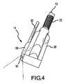
装置10の他の実施形態を図3および4で示している。スコープ28がここでもアブレーション素子18に対して側方に位置付けられている。しかし、スコープ28は、図1および2で示した実施形態よりもさらに遠位に位置付けられている。この構成は、使用者が、肺静脈などの構造物の付近に、またはそれに対して損傷部が作り出されることを望む場合、特に望ましい。図3および4は、最も遠位のアブレーション素子18と実質的に平行に位置付けられたアパチャ30を示しているが、本発明の精神および範囲から逸脱せずに、アパチャ30を最も遠位のアブレーション素子18よりもさらに遠位においても等しく適切に位置付けることが可能である。 Another embodiment of the
図5で示した装置10のさらに他の実施形態では、スコープ28はカラー(collar)33を介してシャフト12にスライド可能に結合されている。図5で示した実施形態では、スコープ28はアブレーション素子18に対して側方に位置付けられている。カラー33は、スコープ28をシャフト12に沿った2つ以上の点に位置付けることができるように、スコープ28がシャフト12に対して遠位方向および近位方向にスライドするのを可能にする。例えば、スコープ28を図5に実線で示したように近位にまず位置付け、これを、アブレーションするべき組織と近傍の解剖学的特徴物とに対する装置10の空間的関係に対する基準としてもよい。次いで医師は、スコープ28をカラー33を介して遠位方向に、ここに点線で示した位置へと前進させて、装置10に対して遠位に位置する特徴物の観察状況を向上させて、例えばアブレーション素子18が僧帽弁狭部の上方に位置付けられていることを検証することができる。したがって図5で示した実施形態では、スコープ28を、アパチャ30をアブレーション素子18の遠位側及び近位側に位置付けられるように調整することが可能である。さらに、カラー33を、シャフト12に回転可能に結合させて、スコープ28をシャフト28を中心に回転させ、アブレーション素子18の平面と平行であり、かつその平面から離隔された複数の平面内に位置付けてもよい。 In yet another embodiment of the
図6は、スコープ28が複数のアパチャ30を含む装置10の実施形態を示している。アパチャ30は様々な方向に向けてよく、これによって医師にアブレーション素子18の正面、上方、側面の視野が追加的に与えられる。さらに、図6は装置10の頂部に取り付けられたスコープ28を示している。即ちスコープ28は、アブレーション素子18に対して側方ではなく、アブレーション素子18の平面と実質的に平行であり、かつその平面から離隔された平面内に位置付けられている。アパチャ30によって取り込まれた画像は、例えば分割画面式または多重モニタ式の構成で並べて表示してもよい。代替方法として、医師は、必要に応じてアパチャ30の間で切り替えて、出力用のアパチャ30を1つ選出してもよい。 FIG. 6 shows an embodiment of the
装置10のさらに他の実施形態を図7で表している。図7では、スコープ28は、アブレーション素子18の平面と実質的に平行であり、かつその平面から離隔された平面内に位置付けられている。スコープ28は単一の、可動式アパチャ30を含む。可動式アパチャ30の使用によって、医者は、処置中に視野を所望の方向に向け、視野を調整することが可能になる。アパチャ30を、玉継ぎ手などの旋回アセンブリ上に取り付けてよく、あるいは他のやり方で連節してもよい。可動式アパチャ30の制御を、ハンドル24に組み込まれた1つまたは複数のアクチュエータを介して行ってもよい。 Yet another embodiment of the
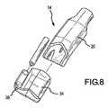
図8は、遠位端部14が透明なキャップ34を受け取るように構成された装置10の実施形態を示している。キャップ34はスコープ28を装置10の遠位端部14に結合する機構、例えば開口部36を提供している。キャップ34を使用すると、スコープ28を迅速かつ簡単に結合および分離することができる。これによって、例えば低侵襲的処置を使用するかどうか依存して、スコープ28を備えた装置10または備えていない装置10のいずれを利用するかという選択肢が医師に与えられる。キャップ34は、アブレーション処置の間にスコープ28を装置10に加える選択肢も医師に与える。 FIG. 8 illustrates an embodiment of the
さらにキャップ34は、装置10の遠位端部14に容易に着脱できるように設計され、かつそのことを目的としている。図9〜14で示したように、スコープ28のアブレーション素子18に対する所望位置に応じて、様々な異なったキャップ34を利用することができる。例えば、1つのキャップ34を、スコープ28をアブレーション素子18に対して側方に位置付けるように構成してもよく(図9〜11)、第2のキャップ34を、スコープ28をアブレーション素子18に対して直交するように位置付けるように構成してもよい(図12〜14)。したがって、医師は、アブレーション処置を開始する前にアブレーション素子18に対するスコープ28の特定の構成を選択し、かつ必要に応じて、処置中にその構成を変更する融通性を有する。 Furthermore, the
キャップ34はまた、アブレーション素子18を超えた遠位方向の視野が必要な場合、そのように延在することができる。その結果、スコープ28の正面に追加的に得られた透明な空間は、例えば移動させなければスコープ28の視野を覆い隠すことになる血液を移動させることによって、標的組織付近の他の解剖学的本体に対する追加の見通しを医師に与えることができる。キャップ34はさらに、アパチャ30が、スコープ28に付着したり、これを阻止したり、またはこれに損傷を与える可能性のある材料と接触しないように保護する。代替方法として、図2で示したものなどのスコープ28上の張出し部(overhang)37がアパチャ30を保護してもよい。 The
装置10はさらに、スコープ28によって取り込まれた視野または画像を縮小する、拡大する、フィルタリングする、または他のやり方で変更するために、レンズまたはフィルタなどの光学素子39を含んでもよい。例えばスコープ28の視野を拡大するために魚眼レンズを利用することもできる。代替的に、スコープ28の視野を変更するために、図7の可動式アパチャ30の実施形態を効果的に模擬した可動式ミラーを利用することもできる。任意で、図8および9で示したように、1つまたは複数の光学素子39がキャップ34に組み込まれている。 The
アブレーションおよび可視化装置10を使用して、PV隔離アブレーション損傷部と隣接した僧帽弁狭部のアブレーション損傷部を作り出してもよい。装置10は、切開部を通して患者の体内へと通される。装置10を、これにスコープ28を予め取り付けて導入してもよいし、あるいは導入後にスコープ28を遠位端部14に取り付けてもよい。 Ablation and
スコープ28によって取り込まれ、収集された画像はディスプレイ上に出力される。必要に応じて、医師はアパチャ30を移動させて、スコープ28の視野を変更することができる。医師はディスプレイ上に出力された視覚情報を利用して、患者の体内で装置10を操縦して、付近の解剖学的構造物と非標的組織とを避けながら、患者の心臓の心外膜面上にアブレーション素子18を適切に位置付けて、僧帽弁狭部のアブレーションを作り出す。医師はまた、ディスプレイを利用して、アブレーション素子18が、PV隔離アブレーション損傷部と隣接した僧帽弁狭部の損傷部を作り出すように位置付けられていることを確認することもできる。PV隔離アブレーション損傷部は、米国特許第7,052,493号で開示されたものなど、肺静脈のまわりを包み込むベルト・タイプのアブレーション装置を使用することによって作り出してもよい。この米国特許第7,052,493号の全体を、本明細書で充分に説明した場合と同じように、参照によって本明細書の一部とする。しかし、当業者であれば、任意の適切な装置を利用して、PV隔離アブレーション損傷部を作り出してもよいことを理解するであろう。 Images captured and collected by the
アブレーション素子18が一度適切に位置付けられると、医師はこれを作動してアブレーションのエネルギーを心臓組織に送達し、ディスプレイを利用して、処置中に拍動している心臓の適切な位置に装置10を維持することが可能である。また、このディスプレイを利用して、処置の終わりにアブレーションが完了したことを視覚的に確認することもできる。 Once the
アブレーション素子18は少なくとも一次元に集束された超音波エネルギーを送達することが好ましい。特に、アブレーション素子18は、約2mmから約20mmの、より好ましくは約2mmから約12mmの、最も好ましくは約8mmの焦点距離を有する集束超音波を送達することが好ましい。別の述べ方をすると、焦点は、装置10の底(または接触)面からここで述べた範囲内の焦点軸(FA)に沿って離隔されている。集束超音波はまた、FAに対して約10度から約170度、より好ましくは約30度から約90度、最も好ましくは約60度の角度を形成する。圧電変換器が利用されることが好ましい。変換器は、エンクロージャとエンクロージャの上に嵌る頂部とを有するハウジングの中に取り付けられることが好ましい。エンクロージャは、エンクロージャの両側に、変換器の湾曲にほぼ一致している湾曲したリップを有してもよい。変換器は、約0.43インチの長さ、約0.35インチの幅、および約0.017インチの厚みを有していることが好ましい。変換器は、上述の好ましい焦点距離と一致した曲率半径(R)を有している。変換器は、上述の好ましい角度範囲内で焦点(F)と角度(A)を形成している。 The
収束超音波エネルギーを使用することの利点は、エネルギーを組織の中に集中させることが可能であることである。集束超音波を使用することの他の利点は、エネルギーが焦点に到達した後に発散し、これによって標的組織を超えた組織に損傷を与える可能性を、平行な超音波エネルギーと比べて軽減することである。心外膜組織を平行な超音波でアブレーションする際、標的組織によって吸収されない平行な超音波エネルギーは心室を通過し、超音波エネルギーが心室の他方側の心内膜面に到達したとき、比較的小さな面積に集中したままとなってしまう。本発明では、超音波エネルギーが焦点を超えて発散し、より大きな面積に拡がることによって他の構造物に損傷を与える可能性を軽減する。 An advantage of using focused ultrasound energy is that it is possible to concentrate the energy in the tissue. Another advantage of using focused ultrasound is that the energy diverges after reaching the focal point, thereby reducing the possibility of damaging tissue beyond the target tissue compared to parallel ultrasound energy. It is. When ablating epicardial tissue with parallel ultrasound, parallel ultrasound energy that is not absorbed by the target tissue passes through the ventricle, and when the ultrasound energy reaches the endocardial surface on the other side of the ventricle, It will remain concentrated in a small area. The present invention mitigates the possibility of damaging other structures by spreading the ultrasonic energy beyond the focal point and spreading it over a larger area.
収束超音波エネルギーは湾曲した変換器で生成されることが好ましいが、集束超音波エネルギーは任意の適切な構造物で作り出してもよい。例えば、音響レンズ化を使用して集束超音波を提供してもよい。音響レンズは、平坦な圧電素子および整合層と使用することができる。さらに、超音波エネルギーは組織に向けて直接放射されることが好ましいが、本発明の範囲から逸脱せずに、表面から反射させて組織に向けてもよい。 Although the focused ultrasound energy is preferably generated with a curved transducer, the focused ultrasound energy may be produced with any suitable structure. For example, acoustic lensing may be used to provide focused ultrasound. Acoustic lenses can be used with flat piezoelectric elements and matching layers. Furthermore, although it is preferred that the ultrasonic energy be emitted directly toward the tissue, it may be reflected from the surface and directed to the tissue without departing from the scope of the present invention.
このエネルギーを、エネルギーの少なくとも約90%などの超音波エネルギーを、本明細書で述べた、長軸またはFAに沿って見た際の好ましい角度範囲および曲率半径内に、集束または集中させるように配向された、いくつかの小型変換器によって生成してもよい。例えば、多重素子の音響位相化されたアレイを使用して、1つまたは複数のセルから音響ビーム操縦能力を提供してもよい。当業者であれば、多重整合層、集束音響レンズ、および非集束音響窓なども使用することができることを理解するであろう。したがって、本発明の範囲から逸脱せずに、ここで述べていない他の方法を含むいくつかの異なったやり方で集束エネルギーを作り出してもよい。 This energy is focused or focused so that ultrasonic energy, such as at least about 90% of the energy, is within the preferred angular range and radius of curvature as described herein along the major axis or FA. It may be produced by several small transducers that are oriented. For example, a multi-element acoustic phased array may be used to provide acoustic beam steering capability from one or more cells. One skilled in the art will appreciate that multiple matching layers, focused acoustic lenses, unfocused acoustic windows, and the like can also be used. Accordingly, the focused energy may be created in a number of different ways, including other methods not described herein, without departing from the scope of the present invention.
本発明の他の態様では、アブレーション・エネルギーの周波数、アブレーション・エネルギーの電力、組織に対する焦点の位置、および/またはアブレーション時間など、装置10の少なくとも1つの特徴を変化させながら、装置10が2つの異なった期間動作される。例えば、装置10を、制御されたやり方で周波数を時間経過とともに変化させて作動させて組織をアブレーションしてもよい。特に、装置10は、組織へのエネルギーの送達を制御することによって経壁損傷部作り出すように作動されることが好ましい。組織をアブレーションする際に周波数を変化させることが好ましいが、当然ながら、本発明の精神および範囲から逸脱せずに、装置10を単一の周波数で作動させることができる。 In other aspects of the invention, the
本発明の第1の処理方法では、変換器は約2MHzから約7MHz、好ましくは約3.5MHzの周波数で、約80ワットから約150ワット、好ましくは約130ワットの電力で、短いバーストで作動する。例えば、変換器を約0.01秒から約2.0秒間、好ましくは約1.2秒間作動してもよい。変換器は、作動と作動の間で、約2秒から約90秒間、より好ましくは約5秒から約80秒間、最も好ましくは約45秒間非活動状態である。このやり方で、制御された量の蓄積エネルギーを短いバーストで組織に送達して、焦点およびその付近の組織を加熱すると同時に遠方表面での血液冷却の影響を最小限に抑えることが可能である。この周波数でのアブレーションを、約0.5キロジュールから約3キロジュールなどの制御された量のエネルギーが送達されるまで継続してもよい。比較的短いバーストでのこの周波数での治療は、焦点での局部的な加熱を生成する。最初の周波数では、エネルギーは、より高い周波数で吸収されるほど急速には組織内に吸収されず、焦点に到達する前の超音波エネルギーの組織内への吸収によって焦点での加熱が大きな影響を受けることはない。 In the first processing method of the present invention, the converter operates in a short burst at a frequency of about 2 MHz to about 7 MHz, preferably about 3.5 MHz, with a power of about 80 watts to about 150 watts, preferably about 130 watts. To do. For example, the transducer may be operated for about 0.01 seconds to about 2.0 seconds, preferably about 1.2 seconds. The transducer is inactive between about 2 seconds to about 90 seconds, more preferably about 5 seconds to about 80 seconds, and most preferably about 45 seconds between actuations. In this manner, a controlled amount of stored energy can be delivered to the tissue in short bursts to heat the focal point and nearby tissue while minimizing the effects of blood cooling at the far surface. Ablation at this frequency may continue until a controlled amount of energy is delivered, such as from about 0.5 kilojoules to about 3 kilojoules. Treatment at this frequency with relatively short bursts produces localized heating at the focal point. At the first frequency, energy is not absorbed into the tissue as rapidly as it is absorbed at higher frequencies, and heating at the focal point has a significant effect on absorption of ultrasonic energy into the tissue before reaching the focal point. I will not receive it.
最初の周波数での治療に続いて、変換器はより長い期間、好ましくは約1秒から約4秒間、より好ましくは約2秒間、焦点と変換器の間の組織をアブレーションするように作動される。この治療中の周波数も、好ましくは約2MHzから約14MHz、より好ましくは約3HMzから約7MHz、最も好ましくは約6MHzである。変換器は、約0.7秒から4秒間、約20ワットから約80ワット、好ましくは約60ワットの電力で作動される。変換器は、作動と作動の間で、約3秒から約60秒の間、好ましくは約40秒間非活動状態である。このやり方で、制御された量のエネルギーを送達して、焦点と変換器の間の組織を加熱することが可能である。この周波数での治療は、約750ジュールなど制御された量の総エネルギーが送達されるまで継続してもよい。 Following treatment at the initial frequency, the transducer is activated to ablate the tissue between the focal point and the transducer for a longer period of time, preferably about 1 second to about 4 seconds, more preferably about 2 seconds. . The frequency during this treatment is also preferably about 2 MHz to about 14 MHz, more preferably about 3 HMz to about 7 MHz, and most preferably about 6 MHz. The transducer is operated from about 20 to about 80 watts, preferably about 60 watts, for about 0.7 to 4 seconds. The transducer is inactive between about 3 seconds to about 60 seconds, preferably about 40 seconds between actuations. In this manner, a controlled amount of energy can be delivered to heat the tissue between the focal point and the transducer. Treatment at this frequency may continue until a controlled amount of total energy, such as about 750 joules, has been delivered.
最終的な治療として、超音波変換器はより高い周波数で作動して付近表面を加熱し、アブレーションする。変換器は、好ましくは約3HMzから約16MHzの間の周波数、好ましくは約6MHzの周波数で作動する。変換器は、上述の治療方法の周波数で超音波エネルギーが組織によって急速に吸収されて、付近表面が急速に加熱されてしまうことから、上述の治療方法よりも低い電力で作動される。一つの好ましい方法では、変換器は約2ワットから約20ワット、より好ましくは約15ワットで作動される。変換器は、約20秒から約80秒、好ましくは約40秒などの、組織をアブレーションするのに充分な継続時間分作動されることが好ましい。付近表面の温度は約70℃から約85℃に到達する場合が多い。 As a final treatment, the ultrasonic transducer operates at a higher frequency to heat and ablate the nearby surface. The transducer preferably operates at a frequency between about 3 HMz and about 16 MHz, preferably about 6 MHz. The transducer is operated at a lower power than the treatment method described above because the ultrasonic energy is rapidly absorbed by the tissue at the frequency of the treatment method described above and the nearby surface is heated rapidly. In one preferred method, the transducer is operated from about 2 watts to about 20 watts, more preferably about 15 watts. The transducer is preferably operated for a duration sufficient to ablate the tissue, such as from about 20 seconds to about 80 seconds, preferably about 40 seconds. The temperature of the nearby surface often reaches about 70 ° C. to about 85 ° C.
上述の治療のそれぞれを、それ自体で使用しても、あるいは他の治療と組み合わせて使用してもよい。さらに、変換器の寸法、電力、周波数、作動時間、および焦点距離の組み合わせを全て、組織への超音波エネルギーの望ましい送達を生成するために変化させてもよい。以上のように、好ましい実施形態を、特徴の1つまたは複数を調整することによって調整してよく、したがって、本発明の精神および範囲から逸脱せずにこれらの変数を変更することができる。上述の一連の治療は一般に、第2の治療でおいてより表面近傍にエネルギーを供給し、第3の治療で、さらに表面近傍にエネルギーを供給する(即ちこの治療手順では、連続的な治療において表面深部から表面近傍へと組織をアブレーションしていく)。 Each of the above treatments may be used by itself or in combination with other treatments. Further, the combination of transducer dimensions, power, frequency, actuation time, and focal length may all be varied to produce the desired delivery of ultrasonic energy to the tissue. As described above, preferred embodiments may be adjusted by adjusting one or more of the features, and thus these variables may be changed without departing from the spirit and scope of the present invention. The series of treatments described above generally provide more energy near the surface in the second treatment, and more energy near the surface in the third treatment (ie, in this treatment procedure, in continuous treatment). Ablation of tissue from deep surface to near surface).
エネルギーを組織内の異なった深さに送達するために、超音波エネルギーの焦点を組織に対して移動させてもよい。アブレーション素子18が作動している間に焦点を移動させてよく、あるいはアブレーション素子18の作動と作動の間に焦点を移動させてもよい。経壁損傷部を作り出すためには、周波数の変更を伴わないで超音波エネルギーの焦点を移動させるだけでもよく、あるいは上述のように周波数の変更と併せて焦点を移動してもよい。焦点は、位相化されたアレイまたは可変音響レンズなどの任意の他のやり方で移動させてもよい。 In order to deliver energy to different depths within the tissue, the focal point of the ultrasonic energy may be moved relative to the tissue. The focal point may be moved while the
この発明の、ある程度の特異性を伴ったいくつかの実施形態を上に述べたが、当業者であれば、この発明の精神または範囲から逸脱せずに、ここに開示した実施形態に対して多数の変更を行うことが可能であろう。例えば、図6は、アブレーション素子18の遠位側に位置付けられたスコープ28を表しているが、当業者であれば、スコープ28を等しく適切に、アブレーション素子18の近位側(即ちハンドル24により近く)に位置付けることも可能であると理解するだろう。さらに、例えば、アブレーション素子18の遠位側に位置付けられた多数の連節されたアパチャ30を備えたスコープ28を設けることによって、あるいはアブレーション素子18の両側で側方に位置付けられた単一のスコープ28を設けることによって、個々の実施形態と関連付けてここで述べた様々な特徴を組み合わせてもよいことも当業者は理解するであろう。 Although several embodiments of the present invention with some specificity have been described above, those skilled in the art will appreciate the embodiments disclosed herein without departing from the spirit or scope of the invention. Many changes could be made. For example, FIG. 6 depicts a
さらに、本装置を、心房細動の治療、特に僧帽弁狭部のアブレーションを作り出す際の標的組織の可視化と関連付けて述べたが、言うまでもなく、本明細書で開示した装置および方法は、他のアブレーション処置における標的組織の可視化についても同等に有益である。例えば、僧帽弁狭部のアブレーション損傷部を作り出すのではなく、本明細書で開示した装置をPV隔離アブレーション損傷部内の間隙を埋めるために使用してもよい。本装置は、他の電気生理学的条件の治療で使用してもよい。 Further, while the device has been described in connection with the treatment of atrial fibrillation, particularly visualization of target tissue in creating ablation of the mitral stenosis, it should be appreciated that the devices and methods disclosed herein are other Equally beneficial is the visualization of the target tissue in this ablation procedure. For example, rather than creating an ablation lesion in the mitral stenosis, the device disclosed herein may be used to fill a gap in the PV isolation ablation lesion. The device may be used in the treatment of other electrophysiological conditions.
方向を示す全ての言葉(例えば上方、下方、上向き、下向き、左、右、左向き、右向き、頂、底、上、下、垂直、水平、時計方向、および反時計方向など)は、読者が本発明を理解しやすいように識別目的で使用したに過ぎず、特に位置、配向、または使用に関して本発明に制限を加えるものではない。接合を示す言葉(例えば取付け、結合、連結等)は、広範囲に解釈するべきものであり、素子同士の連結間の中間部材と、素子同士の相対的な動きとを含んでもよい。以上のように、接合を示すここでの言葉は、2つの素子が直接連結され、互いに固定された関係にあることを必ずしも暗示するものではない。 All words indicating direction (eg up, down, up, down, left, right, left, right, top, bottom, up, down, vertical, horizontal, clockwise and counterclockwise) It has been used for identification purposes only to facilitate understanding of the invention and does not limit the invention, particularly with respect to position, orientation, or use. Words indicating bonding (for example, attachment, coupling, connection, etc.) are to be interpreted in a wide range, and may include an intermediate member between the connections of the elements and a relative movement of the elements. As described above, the term “bond” here does not necessarily imply that the two elements are directly connected and fixed to each other.
以上の記述に含まれた、または添付の図面に示された全ての事項が、例証するためのものに過ぎず、制限を加えるものではないと解釈されることを、本明細書の目的としている。添付の請求項で規定した本発明の精神から逸脱せずに、詳細または構造の変更を行うことができる。 It is the purpose of this specification that all matter contained in the above description or shown in the accompanying drawings is to be interpreted as illustrative only and not limiting. . Changes in detail or structure may be made without departing from the spirit of the invention as defined in the appended claims.
Claims (29)
Translated fromJapanese前記シャフトの前記遠位端部に結合された少なくとも1つのアブレーション素子と、
前記シャフトに前記遠位端部に近接して結合された、少なくとも1つの画像収集用アパチャを含むスコープと、
を備える、組織をアブレーションする装置。A shaft having a distal end;
At least one ablation element coupled to the distal end of the shaft;
A scope including at least one image acquisition aperture coupled to the shaft proximate to the distal end;
A device for ablating tissue, comprising:
前記シャフトの前記遠位端部上に位置する少なくとも2つのアブレーション素子と、
前記シャフトの前記遠位端部に結合された、少なくとも1つの画像収集用アパチャを含むスコープと、
を備える、アブレーションおよび可視化装置。A shaft having a distal end and a proximal end;
At least two ablation elements located on the distal end of the shaft;
A scope including at least one image acquisition aperture coupled to the distal end of the shaft;
An ablation and visualization device comprising:
Applications Claiming Priority (3)
| Application Number | Priority Date | Filing Date | Title |
|---|---|---|---|
| US81588106P | 2006-06-23 | 2006-06-23 | |
| US11/642,923US8052683B2 (en) | 2006-06-23 | 2006-12-21 | Device for ablation and visualization |
| PCT/US2007/071771WO2007149975A2 (en) | 2006-06-23 | 2007-06-21 | Device for ablation and visualization |
Publications (2)
| Publication Number | Publication Date |
|---|---|
| JP2009540962Atrue JP2009540962A (en) | 2009-11-26 |
| JP2009540962A5 JP2009540962A5 (en) | 2010-08-19 |
Family
ID=38834386
Family Applications (1)
| Application Number | Title | Priority Date | Filing Date |
|---|---|---|---|
| JP2009516723APendingJP2009540962A (en) | 2006-06-23 | 2007-06-21 | Ablation and visualization equipment |
Country Status (5)
| Country | Link |
|---|---|
| US (1) | US8052683B2 (en) |
| EP (1) | EP2032062A4 (en) |
| JP (1) | JP2009540962A (en) |
| CN (1) | CN101472532B (en) |
| WO (1) | WO2007149975A2 (en) |
Families Citing this family (15)
| Publication number | Priority date | Publication date | Assignee | Title |
|---|---|---|---|---|
| DE102006057809A1 (en)* | 2006-12-06 | 2008-06-12 | Ruprecht-Karls-Universität Heidelberg | intubation tube |
| US8102734B2 (en)* | 2007-02-08 | 2012-01-24 | St. Jude Medical, Atrial Fibrillation Division, Inc. | High intensity focused ultrasound transducer with acoustic lens |
| WO2009088923A1 (en)* | 2008-01-03 | 2009-07-16 | Maquet Cardiovascular, Llc | Endoscope instruments systems and methods for closed chest epicardial ablation |
| CN101785699A (en)* | 2010-01-04 | 2010-07-28 | 上海祥秀医药科技有限公司 | Prostate removal surgery device with carbon dioxide air source |
| EP2755545B1 (en)* | 2011-09-13 | 2018-10-31 | Covidien LP | Operative element support structure |
| JP5976983B1 (en) | 2013-07-01 | 2016-08-24 | ズーリック・メディカル・コーポレイションZurich Medical Corporation | Apparatus and method for intravascular measurement |
| US10835183B2 (en) | 2013-07-01 | 2020-11-17 | Zurich Medical Corporation | Apparatus and method for intravascular measurements |
| EP4477143A3 (en)* | 2014-09-05 | 2025-03-19 | PROCEPT BioRobotics Corporation | Physician controlled tissue resection integrated with treatment mapping of target organ images |
| CN106236246A (en)* | 2016-08-24 | 2016-12-21 | 王卫东 | Ablating device |
| CN108523991B (en)* | 2018-02-13 | 2020-10-09 | 南京亿高微波系统工程有限公司 | High-efficient refrigerated multi-functional microwave ablation needle |
| US11547277B2 (en)* | 2018-04-12 | 2023-01-10 | Endosound, Inc. | Steerable ultrasound attachment for endoscope |
| CN113117267B (en)* | 2019-12-30 | 2022-11-11 | 重庆融海超声医学工程研究中心有限公司 | Treatment plan making device |
| EP3871585B1 (en)* | 2020-02-28 | 2025-04-09 | Gyrus ACMI, Inc. d/b/a Olympus Surgical Technologies America | Electrosurgical attachment device |
| CN114098922B (en)* | 2021-11-18 | 2024-08-16 | 南京脉创医疗科技有限公司 | Renal artery ablation guide catheter through radial artery |
| CN115581437B (en)* | 2022-10-12 | 2024-07-19 | 北京理工大学 | Optical coherence tomography guided laser minimally invasive diagnosis and treatment endoscopic probe |
Citations (10)
| Publication number | Priority date | Publication date | Assignee | Title |
|---|---|---|---|---|
| JPS6077731A (en)* | 1983-10-03 | 1985-05-02 | オリンパス光学工業株式会社 | Endoscope apparatus using solid-image pick-up element |
| JPH0521901U (en)* | 1991-09-06 | 1993-03-23 | 富士写真光機株式会社 | Passage forming body for in-body examination device |
| JPH11192203A (en)* | 1997-10-31 | 1999-07-21 | Olympus Optical Co Ltd | Endoscope |
| JP2003135378A (en)* | 2001-10-31 | 2003-05-13 | Pentax Corp | Two-channel endoscope |
| JP2003339632A (en)* | 2002-05-23 | 2003-12-02 | Olympus Optical Co Ltd | Endoscope |
| JP2005507731A (en)* | 2001-11-09 | 2005-03-24 | カーディオ−オプティクス, インコーポレイテッド | Direct real-time imaging guidance for cardiac catheterization |
| JP2005137906A (en)* | 2003-11-07 | 2005-06-02 | Siemens Ag | Heart disease ablation device and medical treatment method for heart disease ablation |
| JP2005537867A (en)* | 2002-09-06 | 2005-12-15 | シー・アール・バード・インク | Endoscope attachment adapter |
| JP2006095336A (en)* | 2005-12-26 | 2006-04-13 | Olympus Corp | Treating instrument for cutting living body tissue |
| JP2007537013A (en)* | 2004-05-14 | 2007-12-20 | メドトロニック・インコーポレーテッド | Method for forming an ablated tissue region using high intensity focused ultrasound |
Family Cites Families (33)
| Publication number | Priority date | Publication date | Assignee | Title |
|---|---|---|---|---|
| US2532043A (en)* | 1946-06-18 | 1950-11-28 | American Cystoscope Makers Inc | Instrument for retrograde electrosurgical resection |
| US4068667A (en)* | 1976-09-03 | 1978-01-17 | Iglesias Jose J | Anti-arcing resectoscope |
| JPS6031689Y2 (en)* | 1980-06-10 | 1985-09-21 | オリンパス光学工業株式会社 | High frequency treatment device for endoscope |
| JPS5720261A (en)* | 1980-07-14 | 1982-02-02 | Olympus Optical Co | Medical treating device |
| US5197963A (en)* | 1991-12-02 | 1993-03-30 | Everest Medical Corporation | Electrosurgical instrument with extendable sheath for irrigation and aspiration |
| US5275151A (en)* | 1991-12-11 | 1994-01-04 | Clarus Medical Systems, Inc. | Handle for deflectable catheter |
| US5611777A (en)* | 1993-05-14 | 1997-03-18 | C.R. Bard, Inc. | Steerable electrode catheter |
| US5445142A (en)* | 1994-03-15 | 1995-08-29 | Ethicon Endo-Surgery, Inc. | Surgical trocars having optical tips defining one or more viewing ports |
| US5667472A (en)* | 1994-03-18 | 1997-09-16 | Clarus Medical Systems, Inc. | Surgical instrument and method for use with a viewing system |
| US5492131A (en)* | 1994-09-06 | 1996-02-20 | Guided Medical Systems, Inc. | Servo-catheter |
| US6071274A (en)* | 1996-12-19 | 2000-06-06 | Ep Technologies, Inc. | Loop structures for supporting multiple electrode elements |
| US5849011A (en)* | 1995-06-19 | 1998-12-15 | Vidamed, Inc. | Medical device with trigger actuation assembly |
| US5935125A (en)* | 1996-04-17 | 1999-08-10 | Uros Corporation | Fulguration and cauterization device |
| US6726684B1 (en)* | 1996-07-16 | 2004-04-27 | Arthrocare Corporation | Methods for electrosurgical spine surgery |
| US6106521A (en)* | 1996-08-16 | 2000-08-22 | United States Surgical Corporation | Apparatus for thermal treatment of tissue |
| US6840936B2 (en)* | 1996-10-22 | 2005-01-11 | Epicor Medical, Inc. | Methods and devices for ablation |
| US6311692B1 (en)* | 1996-10-22 | 2001-11-06 | Epicor, Inc. | Apparatus and method for diagnosis and therapy of electrophysiological disease |
| US6719755B2 (en)* | 1996-10-22 | 2004-04-13 | Epicor Medical, Inc. | Methods and devices for ablation |
| US7052493B2 (en)* | 1996-10-22 | 2006-05-30 | Epicor Medical, Inc. | Methods and devices for ablation |
| US6076012A (en)* | 1996-12-19 | 2000-06-13 | Ep Technologies, Inc. | Structures for supporting porous electrode elements |
| US6071279A (en)* | 1996-12-19 | 2000-06-06 | Ep Technologies, Inc. | Branched structures for supporting multiple electrode elements |
| US5873877A (en)* | 1997-04-11 | 1999-02-23 | Vidamed, Inc. | Medical probe device with transparent distal extremity |
| US6086583A (en)* | 1997-06-05 | 2000-07-11 | Asahi Kogaku Kogyo Kabushiki Kaisha | Electric cautery for endoscope |
| US6198974B1 (en)* | 1998-08-14 | 2001-03-06 | Cordis Webster, Inc. | Bi-directional steerable catheter |
| WO2000019926A1 (en)* | 1998-10-05 | 2000-04-13 | Scimed Life Systems, Inc. | Large area thermal ablation |
| US6468265B1 (en)* | 1998-11-20 | 2002-10-22 | Intuitive Surgical, Inc. | Performing cardiac surgery without cardioplegia |
| US6210407B1 (en)* | 1998-12-03 | 2001-04-03 | Cordis Webster, Inc. | Bi-directional electrode catheter |
| US20020107514A1 (en)* | 2000-04-27 | 2002-08-08 | Hooven Michael D. | Transmural ablation device with parallel jaws |
| US6551315B2 (en)* | 2000-12-06 | 2003-04-22 | Syntheon, Llc | Methods and apparatus for the treatment of gastric ulcers |
| US20030181900A1 (en)* | 2002-03-25 | 2003-09-25 | Long Gary L. | Endoscopic ablation system with a plurality of electrodes |
| JP3722729B2 (en)* | 2001-06-04 | 2005-11-30 | オリンパス株式会社 | Endoscope treatment device |
| JP4302602B2 (en) | 2004-09-24 | 2009-07-29 | オリンパス株式会社 | Endoscopic treatment tool, endoscopic treatment system, and support adapter |
| US8216234B2 (en)* | 2004-11-10 | 2012-07-10 | Ethicon Endo-Surgery, Inc. | Tissue resection device |
- 2006
- 2006-12-21USUS11/642,923patent/US8052683B2/ennot_activeExpired - Fee Related
- 2007
- 2007-06-21CNCN2007800232562Apatent/CN101472532B/ennot_activeExpired - Fee Related
- 2007-06-21WOPCT/US2007/071771patent/WO2007149975A2/enactiveApplication Filing
- 2007-06-21JPJP2009516723Apatent/JP2009540962A/enactivePending
- 2007-06-21EPEP07798880Apatent/EP2032062A4/ennot_activeWithdrawn
Patent Citations (10)
| Publication number | Priority date | Publication date | Assignee | Title |
|---|---|---|---|---|
| JPS6077731A (en)* | 1983-10-03 | 1985-05-02 | オリンパス光学工業株式会社 | Endoscope apparatus using solid-image pick-up element |
| JPH0521901U (en)* | 1991-09-06 | 1993-03-23 | 富士写真光機株式会社 | Passage forming body for in-body examination device |
| JPH11192203A (en)* | 1997-10-31 | 1999-07-21 | Olympus Optical Co Ltd | Endoscope |
| JP2003135378A (en)* | 2001-10-31 | 2003-05-13 | Pentax Corp | Two-channel endoscope |
| JP2005507731A (en)* | 2001-11-09 | 2005-03-24 | カーディオ−オプティクス, インコーポレイテッド | Direct real-time imaging guidance for cardiac catheterization |
| JP2003339632A (en)* | 2002-05-23 | 2003-12-02 | Olympus Optical Co Ltd | Endoscope |
| JP2005537867A (en)* | 2002-09-06 | 2005-12-15 | シー・アール・バード・インク | Endoscope attachment adapter |
| JP2005137906A (en)* | 2003-11-07 | 2005-06-02 | Siemens Ag | Heart disease ablation device and medical treatment method for heart disease ablation |
| JP2007537013A (en)* | 2004-05-14 | 2007-12-20 | メドトロニック・インコーポレーテッド | Method for forming an ablated tissue region using high intensity focused ultrasound |
| JP2006095336A (en)* | 2005-12-26 | 2006-04-13 | Olympus Corp | Treating instrument for cutting living body tissue |
Also Published As
| Publication number | Publication date |
|---|---|
| EP2032062A2 (en) | 2009-03-11 |
| US8052683B2 (en) | 2011-11-08 |
| WO2007149975A2 (en) | 2007-12-27 |
| US20070299437A1 (en) | 2007-12-27 |
| EP2032062A4 (en) | 2010-04-14 |
| CN101472532B (en) | 2012-06-27 |
| WO2007149975B1 (en) | 2008-08-28 |
| WO2007149975A3 (en) | 2008-07-17 |
| CN101472532A (en) | 2009-07-01 |
Similar Documents
| Publication | Publication Date | Title |
|---|---|---|
| JP2009540962A (en) | Ablation and visualization equipment | |
| JP5072962B2 (en) | Apparatus and method for ablating tissue | |
| JP4970037B2 (en) | Method and apparatus for non-invasive treatment of atrial fibrillation using high intensity focused ultrasound | |
| US7699845B2 (en) | Ablation device and method with connector | |
| US20190159800A1 (en) | Methods and systems for ablating tissue | |
| CA2550174C (en) | Less invasive systems for ablation of fat pads | |
| AU775394B2 (en) | Apparatus and method for ablating tissue | |
| US20080082109A1 (en) | Robotic surgical system with forward-oriented field of view guide instrument navigation | |
| JP5216986B2 (en) | Device for facilitating tissue treatment with improved application of energy and non-energy modalities | |
| US20160008636A1 (en) | Ultrasound imaging sheath and associated method for guided percutaneous trans-catheter therapy | |
| JP2009540960A5 (en) | ||
| US20090163807A1 (en) | Finger-mounted or robot-mounted transducer device | |
| US20100049099A1 (en) | Method and system for positioning an energy source | |
| US7678109B2 (en) | Ablation device and method comprising movable ablation elements | |
| AU2012232969B2 (en) | Methods and systems for ablating tissue | |
| JP2022533677A (en) | Minimally Invasive Assembly for Lung Ablation |
Legal Events
| Date | Code | Title | Description |
|---|---|---|---|
| A521 | Request for written amendment filed | Free format text:JAPANESE INTERMEDIATE CODE: A523 Effective date:20100621 | |
| A621 | Written request for application examination | Free format text:JAPANESE INTERMEDIATE CODE: A621 Effective date:20100621 | |
| A521 | Request for written amendment filed | Free format text:JAPANESE INTERMEDIATE CODE: A523 Effective date:20100625 | |
| A977 | Report on retrieval | Free format text:JAPANESE INTERMEDIATE CODE: A971007 Effective date:20120528 | |
| A131 | Notification of reasons for refusal | Free format text:JAPANESE INTERMEDIATE CODE: A131 Effective date:20120612 | |
| A521 | Request for written amendment filed | Free format text:JAPANESE INTERMEDIATE CODE: A523 Effective date:20120911 | |
| A02 | Decision of refusal | Free format text:JAPANESE INTERMEDIATE CODE: A02 Effective date:20121218 | |
| A521 | Request for written amendment filed | Free format text:JAPANESE INTERMEDIATE CODE: A523 Effective date:20130417 | |
| A911 | Transfer to examiner for re-examination before appeal (zenchi) | Free format text:JAPANESE INTERMEDIATE CODE: A911 Effective date:20130425 | |
| A912 | Re-examination (zenchi) completed and case transferred to appeal board | Free format text:JAPANESE INTERMEDIATE CODE: A912 Effective date:20130517 | |
| A521 | Request for written amendment filed | Free format text:JAPANESE INTERMEDIATE CODE: A523 Effective date:20140205 |