JP2009540926A - Self-cleaning stent - Google Patents
Self-cleaning stentDownload PDFInfo
- Publication number
- JP2009540926A JP2009540926AJP2009516532AJP2009516532AJP2009540926AJP 2009540926 AJP2009540926 AJP 2009540926AJP 2009516532 AJP2009516532 AJP 2009516532AJP 2009516532 AJP2009516532 AJP 2009516532AJP 2009540926 AJP2009540926 AJP 2009540926A
- Authority
- JP
- Japan
- Prior art keywords
- self
- tubular body
- weighted object
- stent
- cleaning stent
- Prior art date
- Legal status (The legal status is an assumption and is not a legal conclusion. Google has not performed a legal analysis and makes no representation as to the accuracy of the status listed.)
- Withdrawn
Links
- 238000004140cleaningMethods0.000titleclaimsdescription83
- 239000000463materialSubstances0.000claimsabstractdescription56
- 239000012530fluidSubstances0.000claimsabstractdescription19
- 230000033001locomotionEffects0.000claimsabstractdescription12
- 229920000642polymerPolymers0.000claimsdescription26
- 230000007246mechanismEffects0.000claimsdescription17
- 230000000452restraining effectEffects0.000claimsdescription14
- 238000000034methodMethods0.000claimsdescription13
- 230000005484gravityEffects0.000claimsdescription12
- 230000004044responseEffects0.000claimsdescription9
- 238000012423maintenanceMethods0.000claimsdescription6
- 229910001220stainless steelInorganic materials0.000claimsdescription4
- 239000010935stainless steelSubstances0.000claimsdescription4
- 239000000919ceramicSubstances0.000claimsdescription2
- PCHJSUWPFVWCPO-UHFFFAOYSA-NgoldChemical compound[Au]PCHJSUWPFVWCPO-UHFFFAOYSA-N0.000claimsdescription2
- 239000010931goldSubstances0.000claimsdescription2
- 229910052737goldInorganic materials0.000claimsdescription2
- 238000000576coating methodMethods0.000description31
- 239000011248coating agentSubstances0.000description27
- 239000012867bioactive agentSubstances0.000description12
- -1polyethylenePolymers0.000description10
- 241000894006BacteriaSpecies0.000description8
- 239000003242anti bacterial agentSubstances0.000description7
- 210000000013bile ductAnatomy0.000description7
- 229920002988biodegradable polymerPolymers0.000description7
- 239000004621biodegradable polymerSubstances0.000description7
- 230000036961partial effectEffects0.000description7
- 239000002904solventSubstances0.000description7
- JVTAAEKCZFNVCJ-REOHCLBHSA-NL-lactic acidChemical compoundC[C@H](O)C(O)=OJVTAAEKCZFNVCJ-REOHCLBHSA-N0.000description6
- YJQPYGGHQPGBLI-UHFFFAOYSA-NNovobiocinNatural productsO1C(C)(C)C(OC)C(OC(N)=O)C(O)C1OC1=CC=C(C(O)=C(NC(=O)C=2C=C(CC=C(C)C)C(O)=CC=2)C(=O)O2)C2=C1CYJQPYGGHQPGBLI-UHFFFAOYSA-N0.000description6
- 230000003115biocidal effectEffects0.000description6
- 229920001577copolymerPolymers0.000description6
- 239000003814drugSubstances0.000description6
- 238000001125extrusionMethods0.000description6
- 229960002950novobiocinDrugs0.000description6
- YJQPYGGHQPGBLI-KGSXXDOSSA-NnovobiocinChemical compoundO1C(C)(C)[C@H](OC)[C@@H](OC(N)=O)[C@@H](O)[C@@H]1OC1=CC=C(C(O)=C(NC(=O)C=2C=C(CC=C(C)C)C(O)=CC=2)C(=O)O2)C2=C1CYJQPYGGHQPGBLI-KGSXXDOSSA-N0.000description6
- 239000010802sludgeSubstances0.000description6
- FFTVPQUHLQBXQZ-KVUCHLLUSA-N(4s,4as,5ar,12ar)-4,7-bis(dimethylamino)-1,10,11,12a-tetrahydroxy-3,12-dioxo-4a,5,5a,6-tetrahydro-4h-tetracene-2-carboxamideChemical compoundC1C2=C(N(C)C)C=CC(O)=C2C(O)=C2[C@@H]1C[C@H]1[C@H](N(C)C)C(=O)C(C(N)=O)=C(O)[C@@]1(O)C2=OFFTVPQUHLQBXQZ-KVUCHLLUSA-N0.000description5
- 238000000151depositionMethods0.000description5
- 229940079593drugDrugs0.000description5
- 229960004023minocyclineDrugs0.000description5
- 239000004626polylactic acidSubstances0.000description5
- 229920002635polyurethanePolymers0.000description5
- 239000004814polyurethaneSubstances0.000description5
- JQXXHWHPUNPDRT-WLSIYKJHSA-NrifampicinChemical compoundO([C@](C1=O)(C)O/C=C/[C@@H]([C@H]([C@@H](OC(C)=O)[C@H](C)[C@H](O)[C@H](C)[C@@H](O)[C@@H](C)\C=C\C=C(C)/C(=O)NC=2C(O)=C3C([O-])=C4C)C)OC)C4=C1C3=C(O)C=2\C=N\N1CC[NH+](C)CC1JQXXHWHPUNPDRT-WLSIYKJHSA-N0.000description5
- 229960001225rifampicinDrugs0.000description5
- 229940088710antibiotic agentDrugs0.000description4
- 210000000941bileAnatomy0.000description4
- 150000001875compoundsChemical class0.000description4
- 210000001198duodenumAnatomy0.000description4
- 239000000203mixtureSubstances0.000description4
- 229920000747poly(lactic acid)Polymers0.000description4
- YMWUJEATGCHHMB-UHFFFAOYSA-NDichloromethaneChemical compoundClCClYMWUJEATGCHHMB-UHFFFAOYSA-N0.000description3
- ZMXDDKWLCZADIW-UHFFFAOYSA-NN,N-DimethylformamideChemical compoundCN(C)C=OZMXDDKWLCZADIW-UHFFFAOYSA-N0.000description3
- 210000001124body fluidAnatomy0.000description3
- 239000003795chemical substances by applicationSubstances0.000description3
- 239000006185dispersionSubstances0.000description3
- 229920001477hydrophilic polymerPolymers0.000description3
- 239000011159matrix materialSubstances0.000description3
- 229920003023plasticPolymers0.000description3
- 239000004033plasticSubstances0.000description3
- 239000005014poly(hydroxyalkanoate)Substances0.000description3
- 229920000903polyhydroxyalkanoatePolymers0.000description3
- 229920001343polytetrafluoroethylenePolymers0.000description3
- 239000004810polytetrafluoroethyleneSubstances0.000description3
- 239000000126substanceSubstances0.000description3
- BPYKTIZUTYGOLE-IFADSCNNSA-NBilirubinChemical compoundN1C(=O)C(C)=C(C=C)\C1=C\C1=C(C)C(CCC(O)=O)=C(CC2=C(C(C)=C(\C=C/3C(=C(C=C)C(=O)N\3)C)N2)CCC(O)=O)N1BPYKTIZUTYGOLE-IFADSCNNSA-N0.000description2
- 239000004696Poly ether ether ketoneSubstances0.000description2
- 239000004698PolyethyleneSubstances0.000description2
- 241001454746Streptomyces niveusSpecies0.000description2
- 239000004098TetracyclineSubstances0.000description2
- 230000002378acidificating effectEffects0.000description2
- 230000000844anti-bacterial effectEffects0.000description2
- 239000003429antifungal agentSubstances0.000description2
- 229940121375antifungal agentDrugs0.000description2
- 239000004599antimicrobialSubstances0.000description2
- 230000001580bacterial effectEffects0.000description2
- 230000003385bacteriostatic effectEffects0.000description2
- 230000000903blocking effectEffects0.000description2
- 230000015556catabolic processEffects0.000description2
- MYSWGUAQZAJSOK-UHFFFAOYSA-NciprofloxacinChemical compoundC12=CC(N3CCNCC3)=C(F)C=C2C(=O)C(C(=O)O)=CN1C1CC1MYSWGUAQZAJSOK-UHFFFAOYSA-N0.000description2
- 238000004132cross linkingMethods0.000description2
- 239000003431cross linking reagentSubstances0.000description2
- 238000006731degradation reactionMethods0.000description2
- 230000008021depositionEffects0.000description2
- 230000000694effectsEffects0.000description2
- 239000000017hydrogelSubstances0.000description2
- 238000001727in vivoMethods0.000description2
- JVTAAEKCZFNVCJ-UHFFFAOYSA-Nlactic acidChemical compoundCC(O)C(O)=OJVTAAEKCZFNVCJ-UHFFFAOYSA-N0.000description2
- 230000000670limiting effectEffects0.000description2
- 239000007788liquidSubstances0.000description2
- 238000004519manufacturing processMethods0.000description2
- 229920002530polyetherether ketonePolymers0.000description2
- 229920000573polyethylenePolymers0.000description2
- 229920000139polyethylene terephthalatePolymers0.000description2
- 239000005020polyethylene terephthalateSubstances0.000description2
- 230000008569processEffects0.000description2
- 108090000765processed proteins & peptidesProteins0.000description2
- 238000007493shaping processMethods0.000description2
- 238000005507sprayingMethods0.000description2
- 235000019364tetracyclineNutrition0.000description2
- 150000003522tetracyclinesChemical class0.000description2
- 229920002554vinyl polymerPolymers0.000description2
- XLYOFNOQVPJJNP-UHFFFAOYSA-NwaterSubstancesOXLYOFNOQVPJJNP-UHFFFAOYSA-N0.000description2
- PZWQOGNTADJZGH-SNAWJCMRSA-N(2e)-2-methylpenta-2,4-dienoic acidChemical compoundOC(=O)C(/C)=C/C=CPZWQOGNTADJZGH-SNAWJCMRSA-N0.000description1
- RUDATBOHQWOJDD-UHFFFAOYSA-N(3beta,5beta,7alpha)-3,7-Dihydroxycholan-24-oic acidNatural productsOC1CC2CC(O)CCC2(C)C2C1C1CCC(C(CCC(O)=O)C)C1(C)CC2RUDATBOHQWOJDD-UHFFFAOYSA-N0.000description1
- SGKRLCUYIXIAHR-AKNGSSGZSA-N(4s,4ar,5s,5ar,6r,12ar)-4-(dimethylamino)-1,5,10,11,12a-pentahydroxy-6-methyl-3,12-dioxo-4a,5,5a,6-tetrahydro-4h-tetracene-2-carboxamideChemical compoundC1=CC=C2[C@H](C)[C@@H]([C@H](O)[C@@H]3[C@](C(O)=C(C(N)=O)C(=O)[C@H]3N(C)C)(O)C3=O)C3=C(O)C2=C1OSGKRLCUYIXIAHR-AKNGSSGZSA-N0.000description1
- SMZOUWXMTYCWNB-UHFFFAOYSA-N2-(2-methoxy-5-methylphenyl)ethanamineChemical compoundCOC1=CC=C(C)C=C1CCNSMZOUWXMTYCWNB-UHFFFAOYSA-N0.000description1
- NIXOWILDQLNWCW-UHFFFAOYSA-N2-Propenoic acidNatural productsOC(=O)C=CNIXOWILDQLNWCW-UHFFFAOYSA-N0.000description1
- QCQCHGYLTSGIGX-GHXANHINSA-N4-[[(3ar,5ar,5br,7ar,9s,11ar,11br,13as)-5a,5b,8,8,11a-pentamethyl-3a-[(5-methylpyridine-3-carbonyl)amino]-2-oxo-1-propan-2-yl-4,5,6,7,7a,9,10,11,11b,12,13,13a-dodecahydro-3h-cyclopenta[a]chrysen-9-yl]oxy]-2,2-dimethyl-4-oxobutanoic acidChemical compoundN([C@@]12CC[C@@]3(C)[C@]4(C)CC[C@H]5C(C)(C)[C@@H](OC(=O)CC(C)(C)C(O)=O)CC[C@]5(C)[C@H]4CC[C@@H]3C1=C(C(C2)=O)C(C)C)C(=O)C1=CN=CC(C)=C1QCQCHGYLTSGIGX-GHXANHINSA-N0.000description1
- HBAQYPYDRFILMT-UHFFFAOYSA-N8-[3-(1-cyclopropylpyrazol-4-yl)-1H-pyrazolo[4,3-d]pyrimidin-5-yl]-3-methyl-3,8-diazabicyclo[3.2.1]octan-2-oneChemical classC1(CC1)N1N=CC(=C1)C1=NNC2=C1N=C(N=C2)N1C2C(N(CC1CC2)C)=OHBAQYPYDRFILMT-UHFFFAOYSA-N0.000description1
- GJCOSYZMQJWQCA-UHFFFAOYSA-N9H-xantheneChemical compoundC1=CC=C2CC3=CC=CC=C3OC2=C1GJCOSYZMQJWQCA-UHFFFAOYSA-N0.000description1
- 229920002126Acrylic acid copolymerPolymers0.000description1
- 229920001817AgarPolymers0.000description1
- APKFDSVGJQXUKY-KKGHZKTASA-NAmphotericin-BNatural productsO[C@H]1[C@@H](N)[C@H](O)[C@@H](C)O[C@H]1O[C@H]1C=CC=CC=CC=CC=CC=CC=C[C@H](C)[C@@H](O)[C@@H](C)[C@H](C)OC(=O)C[C@H](O)C[C@H](O)CC[C@@H](O)[C@H](O)C[C@H](O)C[C@](O)(C[C@H](O)[C@H]2C(O)=O)O[C@H]2C1APKFDSVGJQXUKY-KKGHZKTASA-N0.000description1
- 108020000946Bacterial DNAProteins0.000description1
- 108010077805Bacterial ProteinsProteins0.000description1
- 206010056375Bile duct obstructionDiseases0.000description1
- 206010051341Bile duct stenosisDiseases0.000description1
- 206010004637Bile duct stoneDiseases0.000description1
- OYPRJOBELJOOCE-UHFFFAOYSA-NCalciumChemical compound[Ca]OYPRJOBELJOOCE-UHFFFAOYSA-N0.000description1
- 229920002134Carboxymethyl cellulosePolymers0.000description1
- 229930186147CephalosporinNatural products0.000description1
- 206010008609Cholangitis sclerosingDiseases0.000description1
- 206010008635CholestasisDiseases0.000description1
- 208000017667Chronic DiseaseDiseases0.000description1
- 208000000668Chronic PancreatitisDiseases0.000description1
- 208000035473Communicable diseaseDiseases0.000description1
- 244000303965Cyamopsis psoralioidesSpecies0.000description1
- XZMCDFZZKTWFGF-UHFFFAOYSA-NCyanamideChemical compoundNC#NXZMCDFZZKTWFGF-UHFFFAOYSA-N0.000description1
- JVTAAEKCZFNVCJ-UWTATZPHSA-ND-lactic acidChemical compoundC[C@@H](O)C(O)=OJVTAAEKCZFNVCJ-UWTATZPHSA-N0.000description1
- 102000004163DNA-directed RNA polymerasesHuman genes0.000description1
- 108090000626DNA-directed RNA polymerasesProteins0.000description1
- 208000036828Device occlusionDiseases0.000description1
- 229920002307DextranPolymers0.000description1
- 229920001353DextrinPolymers0.000description1
- 239000004375DextrinSubstances0.000description1
- LFQSCWFLJHTTHZ-UHFFFAOYSA-NEthanolChemical compoundCCOLFQSCWFLJHTTHZ-UHFFFAOYSA-N0.000description1
- RYECOJGRJDOGPP-UHFFFAOYSA-NEthylureaChemical compoundCCNC(N)=ORYECOJGRJDOGPP-UHFFFAOYSA-N0.000description1
- 206010016717FistulaDiseases0.000description1
- 241000233866FungiSpecies0.000description1
- IECPWNUMDGFDKC-UHFFFAOYSA-NFusicsaeureNatural productsC12C(O)CC3C(=C(CCC=C(C)C)C(O)=O)C(OC(C)=O)CC3(C)C1(C)CCC1C2(C)CCC(O)C1CIECPWNUMDGFDKC-UHFFFAOYSA-N0.000description1
- 229920002306GlycocalyxPolymers0.000description1
- 229920002683GlycosaminoglycanPolymers0.000description1
- 206010023129Jaundice cholestaticDiseases0.000description1
- FYYHWMGAXLPEAU-UHFFFAOYSA-NMagnesiumChemical compound[Mg]FYYHWMGAXLPEAU-UHFFFAOYSA-N0.000description1
- WHNWPMSKXPGLAX-UHFFFAOYSA-NN-Vinyl-2-pyrrolidoneChemical compoundC=CN1CCCC1=OWHNWPMSKXPGLAX-UHFFFAOYSA-N0.000description1
- GRYLNZFGIOXLOG-UHFFFAOYSA-NNitric acidChemical groupO[N+]([O-])=OGRYLNZFGIOXLOG-UHFFFAOYSA-N0.000description1
- 239000004677NylonSubstances0.000description1
- 229920002292Nylon 6Polymers0.000description1
- 229920002302Nylon 6,6Polymers0.000description1
- 201000005267Obstructive JaundiceDiseases0.000description1
- 206010033649Pancreatitis chronicDiseases0.000description1
- 229930182555PenicillinNatural products0.000description1
- 229920003171Poly (ethylene oxide)Polymers0.000description1
- 239000004952PolyamideSubstances0.000description1
- 229920002873PolyethyleniminePolymers0.000description1
- 229920000954PolyglycolidePolymers0.000description1
- 229920000331PolyhydroxybutyratePolymers0.000description1
- 239000004743PolypropyleneSubstances0.000description1
- 239000004793PolystyreneSubstances0.000description1
- 240000004808Saccharomyces cerevisiaeSpecies0.000description1
- 206010040047SepsisDiseases0.000description1
- FAPWRFPIFSIZLT-UHFFFAOYSA-MSodium chlorideChemical compound[Na+].[Cl-]FAPWRFPIFSIZLT-UHFFFAOYSA-M0.000description1
- 241000187747StreptomycesSpecies0.000description1
- 229920004695VICTREX™ PEEKPolymers0.000description1
- 241000700605VirusesSpecies0.000description1
- HCHKCACWOHOZIP-UHFFFAOYSA-NZincChemical compound[Zn]HCHKCACWOHOZIP-UHFFFAOYSA-N0.000description1
- 230000035508accumulationEffects0.000description1
- 238000009825accumulationMethods0.000description1
- 239000002253acidSubstances0.000description1
- 230000001154acute effectEffects0.000description1
- 239000000654additiveSubstances0.000description1
- 230000000996additive effectEffects0.000description1
- 239000008272agarSubstances0.000description1
- 229940061720alpha hydroxy acidDrugs0.000description1
- 150000001280alpha hydroxy acidsChemical class0.000description1
- 229940126575aminoglycosideDrugs0.000description1
- 229960003022amoxicillinDrugs0.000description1
- LSQZJLSUYDQPKJ-NJBDSQKTSA-NamoxicillinChemical compoundC1([C@@H](N)C(=O)N[C@H]2[C@H]3SC([C@@H](N3C2=O)C(O)=O)(C)C)=CC=C(O)C=C1LSQZJLSUYDQPKJ-NJBDSQKTSA-N0.000description1
- APKFDSVGJQXUKY-INPOYWNPSA-Namphotericin BChemical compoundO[C@H]1[C@@H](N)[C@H](O)[C@@H](C)O[C@H]1O[C@H]1/C=C/C=C/C=C/C=C/C=C/C=C/C=C/[C@H](C)[C@@H](O)[C@@H](C)[C@H](C)OC(=O)C[C@H](O)C[C@H](O)CC[C@@H](O)[C@H](O)C[C@H](O)C[C@](O)(C[C@H](O)[C@H]2C(O)=O)O[C@H]2C1APKFDSVGJQXUKY-INPOYWNPSA-N0.000description1
- 229960003942amphotericin bDrugs0.000description1
- 150000003851azolesChemical class0.000description1
- 230000004888barrier functionEffects0.000description1
- 230000008901benefitEffects0.000description1
- JUPQTSLXMOCDHR-UHFFFAOYSA-Nbenzene-1,4-diol;bis(4-fluorophenyl)methanoneChemical compoundOC1=CC=C(O)C=C1.C1=CC(F)=CC=C1C(=O)C1=CC=C(F)C=C1JUPQTSLXMOCDHR-UHFFFAOYSA-N0.000description1
- 210000003445biliary tractAnatomy0.000description1
- 229920000249biocompatible polymerPolymers0.000description1
- 238000006065biodegradation reactionMethods0.000description1
- 239000012620biological materialSubstances0.000description1
- 230000015572biosynthetic processEffects0.000description1
- 229920001400block copolymerPolymers0.000description1
- 239000011575calciumSubstances0.000description1
- 229910052791calciumInorganic materials0.000description1
- HRBZRZSCMANEHQ-UHFFFAOYSA-Lcalcium;hexadecanoateChemical compound[Ca+2].CCCCCCCCCCCCCCCC([O-])=O.CCCCCCCCCCCCCCCC([O-])=OHRBZRZSCMANEHQ-UHFFFAOYSA-L0.000description1
- 238000003490calenderingMethods0.000description1
- 229940041011carbapenemsDrugs0.000description1
- 239000001768carboxy methyl celluloseSubstances0.000description1
- 235000010948carboxy methyl celluloseNutrition0.000description1
- 125000002843carboxylic acid groupChemical group0.000description1
- 239000008112carboxymethyl-celluloseSubstances0.000description1
- 239000000679carrageenanSubstances0.000description1
- 229920001525carrageenanPolymers0.000description1
- 235000010418carrageenanNutrition0.000description1
- 229940113118carrageenanDrugs0.000description1
- 238000005266castingMethods0.000description1
- WZOZEZRFJCJXNZ-ZBFHGGJFSA-NcefoxitinChemical compoundN([C@]1(OC)C(N2C(=C(COC(N)=O)CS[C@@H]21)C(O)=O)=O)C(=O)CC1=CC=CS1WZOZEZRFJCJXNZ-ZBFHGGJFSA-N0.000description1
- 229960002682cefoxitinDrugs0.000description1
- 229960000484ceftazidimeDrugs0.000description1
- NMVPEQXCMGEDNH-TZVUEUGBSA-Nceftazidime pentahydrateChemical compoundO.O.O.O.O.S([C@@H]1[C@@H](C(N1C=1C([O-])=O)=O)NC(=O)\C(=N/OC(C)(C)C(O)=O)C=2N=C(N)SC=2)CC=1C[N+]1=CC=CC=C1NMVPEQXCMGEDNH-TZVUEUGBSA-N0.000description1
- 210000000170cell membraneAnatomy0.000description1
- 229940124587cephalosporinDrugs0.000description1
- 150000001780cephalosporinsChemical class0.000description1
- 229960005091chloramphenicolDrugs0.000description1
- WIIZWVCIJKGZOK-RKDXNWHRSA-NchloramphenicolChemical compoundClC(Cl)C(=O)N[C@H](CO)[C@H](O)C1=CC=C([N+]([O-])=O)C=C1WIIZWVCIJKGZOK-RKDXNWHRSA-N0.000description1
- 235000019365chlortetracyclineNutrition0.000description1
- 208000003167cholangitisDiseases0.000description1
- 229960003405ciprofloxacinDrugs0.000description1
- 229960002227clindamycinDrugs0.000description1
- KDLRVYVGXIQJDK-AWPVFWJPSA-NclindamycinChemical compoundCN1C[C@H](CCC)C[C@H]1C(=O)N[C@H]([C@H](C)Cl)[C@@H]1[C@H](O)[C@H](O)[C@@H](O)[C@@H](SC)O1KDLRVYVGXIQJDK-AWPVFWJPSA-N0.000description1
- 229920001688coating polymerPolymers0.000description1
- 239000013078crystalSubstances0.000description1
- LKFHUFAEFBRVQX-UHFFFAOYSA-Ndecanedioic acid;propane-1,2,3-triolChemical compoundOCC(O)CO.OC(=O)CCCCCCCCC(O)=OLKFHUFAEFBRVQX-UHFFFAOYSA-N0.000description1
- 230000001419dependent effectEffects0.000description1
- 238000005137deposition processMethods0.000description1
- 235000019425dextrinNutrition0.000description1
- 230000001079digestive effectEffects0.000description1
- 238000007598dipping methodMethods0.000description1
- 239000002270dispersing agentSubstances0.000description1
- 229960003722doxycyclineDrugs0.000description1
- 238000001035dryingMethods0.000description1
- 229920001971elastomerPolymers0.000description1
- 239000000806elastomerSubstances0.000description1
- 150000002148estersChemical class0.000description1
- 229920001038ethylene copolymerPolymers0.000description1
- 239000005038ethylene vinyl acetateSubstances0.000description1
- 230000008020evaporationEffects0.000description1
- 238000001704evaporationMethods0.000description1
- 230000003890fistulaEffects0.000description1
- XRECTZIEBJDKEO-UHFFFAOYSA-NflucytosineChemical compoundNC1=NC(=O)NC=C1FXRECTZIEBJDKEO-UHFFFAOYSA-N0.000description1
- 229960004413flucytosineDrugs0.000description1
- 229960004675fusidic acidDrugs0.000description1
- IECPWNUMDGFDKC-MZJAQBGESA-Nfusidic acidChemical compoundO[C@@H]([C@@H]12)C[C@H]3\C(=C(/CCC=C(C)C)C(O)=O)[C@@H](OC(C)=O)C[C@]3(C)[C@@]2(C)CC[C@@H]2[C@]1(C)CC[C@@H](O)[C@H]2CIECPWNUMDGFDKC-MZJAQBGESA-N0.000description1
- 210000001035gastrointestinal tractAnatomy0.000description1
- 210000004517glycocalyxAnatomy0.000description1
- 238000010438heat treatmentMethods0.000description1
- 239000008240homogeneous mixtureSubstances0.000description1
- 238000002513implantationMethods0.000description1
- 208000015181infectious diseaseDiseases0.000description1
- 230000002401inhibitory effectEffects0.000description1
- 125000003010ionic groupChemical group0.000description1
- 229920000554ionomerPolymers0.000description1
- 230000007794irritationEffects0.000description1
- 235000014655lactic acidNutrition0.000description1
- 239000004310lactic acidSubstances0.000description1
- 230000007774longtermEffects0.000description1
- 239000003120macrolide antibiotic agentSubstances0.000description1
- 229940041033macrolidesDrugs0.000description1
- 239000011777magnesiumSubstances0.000description1
- 229910052749magnesiumInorganic materials0.000description1
- 229920000609methyl cellulosePolymers0.000description1
- 239000001923methylcelluloseSubstances0.000description1
- 229960000282metronidazoleDrugs0.000description1
- VAOCPAMSLUNLGC-UHFFFAOYSA-NmetronidazoleChemical compoundCC1=NC=C([N+]([O-])=O)N1CCOVAOCPAMSLUNLGC-UHFFFAOYSA-N0.000description1
- 244000005700microbiomeSpecies0.000description1
- 238000002156mixingMethods0.000description1
- 238000012986modificationMethods0.000description1
- 230000004048modificationEffects0.000description1
- 229940041009monobactamsDrugs0.000description1
- 239000000178monomerSubstances0.000description1
- 238000000465mouldingMethods0.000description1
- WWJFFVUVFNBJTN-UHFFFAOYSA-Nneopolyoxin CNatural productsC=1C=C(O)C=NC=1C(O)C(C)C(N)C(=O)NC(C(O)=O)C(C(C1O)O)OC1N1C=CC(=O)NC1=OWWJFFVUVFNBJTN-UHFFFAOYSA-N0.000description1
- HLXZNVUGXRDIFK-UHFFFAOYSA-Nnickel titaniumChemical compound[Ti].[Ti].[Ti].[Ti].[Ti].[Ti].[Ti].[Ti].[Ti].[Ti].[Ti].[Ni].[Ni].[Ni].[Ni].[Ni].[Ni].[Ni].[Ni].[Ni].[Ni].[Ni].[Ni].[Ni].[Ni]HLXZNVUGXRDIFK-UHFFFAOYSA-N0.000description1
- 229910001000nickel titaniumInorganic materials0.000description1
- WWJFFVUVFNBJTN-VHDFTHOZSA-Nnikkomycin ZChemical compoundN1([C@@H]2O[C@@H]([C@H]([C@H]2O)O)[C@H](NC(=O)[C@@H](N)[C@H](C)[C@H](O)C=2N=CC(O)=CC=2)C(O)=O)C=CC(=O)NC1=OWWJFFVUVFNBJTN-VHDFTHOZSA-N0.000description1
- 231100000252nontoxicToxicity0.000description1
- 230000003000nontoxic effectEffects0.000description1
- 229960001180norfloxacinDrugs0.000description1
- OGJPXUAPXNRGGI-UHFFFAOYSA-NnorfloxacinChemical compoundC1=C2N(CC)C=C(C(O)=O)C(=O)C2=CC(F)=C1N1CCNCC1OGJPXUAPXNRGGI-UHFFFAOYSA-N0.000description1
- 238000001668nucleic acid synthesisMethods0.000description1
- 229920001778nylonPolymers0.000description1
- LSQZJLSUYDQPKJ-UHFFFAOYSA-Np-HydroxyampicillinNatural productsO=C1N2C(C(O)=O)C(C)(C)SC2C1NC(=O)C(N)C1=CC=C(O)C=C1LSQZJLSUYDQPKJ-UHFFFAOYSA-N0.000description1
- 244000052769pathogenSpecies0.000description1
- 230000001575pathological effectEffects0.000description1
- 230000007170pathologyEffects0.000description1
- 150000002960penicillinsChemical class0.000description1
- 230000004260plant-type cell wall biogenesisEffects0.000description1
- 239000005015poly(hydroxybutyrate)Substances0.000description1
- 229920002401polyacrylamidePolymers0.000description1
- 229920000058polyacrylatePolymers0.000description1
- 229920002239polyacrylonitrilePolymers0.000description1
- 229920002647polyamidePolymers0.000description1
- 229920001748polybutylenePolymers0.000description1
- 239000004417polycarbonateSubstances0.000description1
- 229920000515polycarbonatePolymers0.000description1
- 229920000728polyesterPolymers0.000description1
- 229920000570polyetherPolymers0.000description1
- 229920000193polymethacrylatePolymers0.000description1
- 229920000098polyolefinPolymers0.000description1
- 229920006324polyoxymethylenePolymers0.000description1
- 229920001155polypropylenePolymers0.000description1
- 229920001296polysiloxanePolymers0.000description1
- 229920002223polystyrenePolymers0.000description1
- 229920002451polyvinyl alcoholPolymers0.000description1
- 239000004800polyvinyl chlorideSubstances0.000description1
- 230000002980postoperative effectEffects0.000description1
- 239000000843powderSubstances0.000description1
- 201000000742primary sclerosing cholangitisDiseases0.000description1
- 102000004196processed proteins & peptidesHuman genes0.000description1
- 238000001243protein synthesisMethods0.000description1
- 108090000623proteins and genesProteins0.000description1
- 102000004169proteins and genesHuman genes0.000description1
- 150000007660quinolonesChemical class0.000description1
- 238000010526radical polymerization reactionMethods0.000description1
- 229920005604random copolymerPolymers0.000description1
- 230000000306recurrent effectEffects0.000description1
- SQTCRTQCPJICLD-KTQDUKAHSA-Nrifamycin BChemical classOC1=C(C(O)=C2C)C3=C(OCC(O)=O)C=C1NC(=O)\C(C)=C/C=C/[C@H](C)[C@H](O)[C@@H](C)[C@@H](O)[C@@H](C)[C@H](OC(C)=O)[C@H](C)[C@@H](OC)\C=C\O[C@@]1(C)OC2=C3C1=OSQTCRTQCPJICLD-KTQDUKAHSA-N0.000description1
- 208000010157sclerosing cholangitisDiseases0.000description1
- 229920000260silasticPolymers0.000description1
- 229920002379silicone rubberPolymers0.000description1
- 239000004945silicone rubberSubstances0.000description1
- 239000011780sodium chlorideSubstances0.000description1
- 229910001415sodium ionInorganic materials0.000description1
- 239000008223sterile waterSubstances0.000description1
- 238000006467substitution reactionMethods0.000description1
- 125000000542sulfonic acid groupChemical group0.000description1
- 208000024891symptomDiseases0.000description1
- 229960002180tetracyclineDrugs0.000description1
- 229930101283tetracyclineNatural products0.000description1
- 229940040944tetracyclinesDrugs0.000description1
- 229920001169thermoplasticPolymers0.000description1
- 239000012815thermoplastic materialSubstances0.000description1
- 239000004416thermosoftening plasticSubstances0.000description1
- 230000014616translationEffects0.000description1
- 229960001082trimethoprimDrugs0.000description1
- IEDVJHCEMCRBQM-UHFFFAOYSA-NtrimethoprimChemical compoundCOC1=C(OC)C(OC)=CC(CC=2C(=NC(N)=NC=2)N)=C1IEDVJHCEMCRBQM-UHFFFAOYSA-N0.000description1
- 238000009827uniform distributionMethods0.000description1
- RUDATBOHQWOJDD-UZVSRGJWSA-Nursodeoxycholic acidChemical compoundC([C@H]1C[C@@H]2O)[C@H](O)CC[C@]1(C)[C@@H]1[C@@H]2[C@@H]2CC[C@H]([C@@H](CCC(O)=O)C)[C@@]2(C)CC1RUDATBOHQWOJDD-UZVSRGJWSA-N0.000description1
- 229960001661ursodiolDrugs0.000description1
- 125000000391vinyl groupChemical group[H]C([*])=C([H])[H]0.000description1
- 229920001285xanthan gumPolymers0.000description1
- 239000011701zincSubstances0.000description1
- 229910052725zincInorganic materials0.000description1
- UHVMMEOXYDMDKI-JKYCWFKZSA-Lzinc;1-(5-cyanopyridin-2-yl)-3-[(1s,2s)-2-(6-fluoro-2-hydroxy-3-propanoylphenyl)cyclopropyl]urea;diacetateChemical compound[Zn+2].CC([O-])=O.CC([O-])=O.CCC(=O)C1=CC=C(F)C([C@H]2[C@H](C2)NC(=O)NC=2N=CC(=CC=2)C#N)=C1OUHVMMEOXYDMDKI-JKYCWFKZSA-L0.000description1
- PAPBSGBWRJIAAV-UHFFFAOYSA-Nε-CaprolactoneChemical compoundO=C1CCCCCO1PAPBSGBWRJIAAV-UHFFFAOYSA-N0.000description1
Images


Classifications
- A—HUMAN NECESSITIES
- A61—MEDICAL OR VETERINARY SCIENCE; HYGIENE
- A61F—FILTERS IMPLANTABLE INTO BLOOD VESSELS; PROSTHESES; DEVICES PROVIDING PATENCY TO, OR PREVENTING COLLAPSING OF, TUBULAR STRUCTURES OF THE BODY, e.g. STENTS; ORTHOPAEDIC, NURSING OR CONTRACEPTIVE DEVICES; FOMENTATION; TREATMENT OR PROTECTION OF EYES OR EARS; BANDAGES, DRESSINGS OR ABSORBENT PADS; FIRST-AID KITS
- A61F2/00—Filters implantable into blood vessels; Prostheses, i.e. artificial substitutes or replacements for parts of the body; Appliances for connecting them with the body; Devices providing patency to, or preventing collapsing of, tubular structures of the body, e.g. stents
- A61F2/82—Devices providing patency to, or preventing collapsing of, tubular structures of the body, e.g. stents
- A—HUMAN NECESSITIES
- A61—MEDICAL OR VETERINARY SCIENCE; HYGIENE
- A61B—DIAGNOSIS; SURGERY; IDENTIFICATION
- A61B17/00—Surgical instruments, devices or methods
- A61B17/22—Implements for squeezing-off ulcers or the like on inner organs of the body; Implements for scraping-out cavities of body organs, e.g. bones; for invasive removal or destruction of calculus using mechanical vibrations; for removing obstructions in blood vessels, not otherwise provided for
- A—HUMAN NECESSITIES
- A61—MEDICAL OR VETERINARY SCIENCE; HYGIENE
- A61B—DIAGNOSIS; SURGERY; IDENTIFICATION
- A61B17/00—Surgical instruments, devices or methods
- A61B17/32—Surgical cutting instruments
- A61B2017/320004—Surgical cutting instruments abrasive
- A—HUMAN NECESSITIES
- A61—MEDICAL OR VETERINARY SCIENCE; HYGIENE
- A61B—DIAGNOSIS; SURGERY; IDENTIFICATION
- A61B17/00—Surgical instruments, devices or methods
- A61B17/32—Surgical cutting instruments
- A61B2017/320004—Surgical cutting instruments abrasive
- A61B2017/320012—Brushes
Landscapes
- Health & Medical Sciences (AREA)
- Engineering & Computer Science (AREA)
- Biomedical Technology (AREA)
- Life Sciences & Earth Sciences (AREA)
- General Health & Medical Sciences (AREA)
- Transplantation (AREA)
- Heart & Thoracic Surgery (AREA)
- Vascular Medicine (AREA)
- Cardiology (AREA)
- Animal Behavior & Ethology (AREA)
- Oral & Maxillofacial Surgery (AREA)
- Public Health (AREA)
- Veterinary Medicine (AREA)
- Media Introduction/Drainage Providing Device (AREA)
- Prostheses (AREA)
- External Artificial Organs (AREA)
- Materials For Medical Uses (AREA)
Abstract
Translated fromJapaneseDescription
Translated fromJapanese関連出願
本特許文献は、米国特許法第119(e)条に基づき、2006年6月22日出願の米国仮特許出願第60/815,646号の出願日の利益を主張し、全体として参照により本明細書の一部とする。RELATED APPLICATIONS This patent document claims the benefit of the filing date of US Provisional Patent Application No. 60 / 815,646, filed June 22, 2006, based on Section 119 (e) of the US Patent Act, and is generally referenced. As a part of this specification.
本発明は、埋め込み可能型医療器具に関する。より詳細には、本発明は、胆道での使用向けに構成されたステントを含むステントに関する。 The present invention relates to an implantable medical device. More particularly, the present invention relates to stents including stents configured for use in the biliary tract.
ステントは狭小化した体管腔の開存を拡大したり、拡張したり、又は維持したりするために使用されることが多い。非拡張型ステントは典型的にはプラスチック製であり、全長を貫通するルーメンを含む。 Stents are often used to expand, expand, or maintain the patency of narrowed body lumens. Non-expandable stents are typically made of plastic and include a lumen that penetrates the entire length.
胆管ステント構造物の埋め込みにより、閉塞性黄疸などの様々な病態の処置が行われる。胆管ステント留置術の処置手法を用いることで、胆汁瘻又は巨大総胆管結石などの病態の短期的な処置を行うことができる。胆管ステントを埋め込むことにより、術後胆管狭窄、原発性硬化性胆管炎及び慢性膵炎などの慢性病態を処置し得る。 Treatment of various pathologies such as obstructive jaundice is performed by implantation of a biliary stent structure. By using a biliary stenting technique, a short-term treatment of a pathological condition such as a bile fistula or a giant common bile duct stone can be performed. By implanting biliary stents, chronic conditions such as postoperative bile duct stenosis, primary sclerosing cholangitis and chronic pancreatitis can be treated.
胆管ステントはポリマーチューブの形態で作製され得るもので、送達カテーテルに載って内視鏡を通じて前進し、胆管内に至り、そこで展開される。チューブ状ステントは圧潰に耐える十分な強度のものが選択されることで開放されたルーメンを維持でき、そこを通じて消化液が消化管に流れ込む。かかるステントの望ましい特徴として、鋭角の屈曲部を含み得る経路に沿って前進できるよう、長手方向に可撓性を有することが挙げられる。ステントはまた、胆管内でその意図する位置を維持して、当該位置から移動しないものでなければならない。 A biliary stent can be made in the form of a polymer tube, which is mounted on a delivery catheter, advanced through an endoscope, into the bile duct and deployed there. Tubular stents are selected to be strong enough to withstand crushing to maintain an open lumen through which digestive fluid flows into the digestive tract. A desirable feature of such a stent is that it is longitudinally flexible so that it can be advanced along a path that may include acute bends. The stent must also maintain its intended position within the bile duct and not move from that position.
体液がステントのルーメンを通って移動するとき、体液中の蓄積性物質がステントの内表面に付着する。蓄積性物質は妨げられることがなければステントを通過していく物質であるが、そうでなければ通路の表面上に蓄積して流路の直径を低減し得るとともに、最終的にはステントを詰まらせる。蓄積性物質としては、限定はされないが、バイオフィルム、細菌増殖、及びスラッジ堆積が挙げられる。従って、蓄積性物質はそれ以上の体液の通過を妨げ得る。積み重なった無定形の生体物質及び細菌などの蓄積物(「スラッジ」)がステントの表面上に蓄積してステントのルーメンを徐々に塞ぐと、胆管ステントは胆管内で閉塞状態となり得る。胆泥は無定形の物質であり、ビリルビンカルシウム及びパルミチン酸カルシウムの結晶を、相当量の様々なタンパク質及び細菌と共に含むことが多い。細菌の存在下では、スラッジは急速に挿入物の上に堆積し得る。例えば細菌は、線毛を通じて、又はムコ多糖被膜の生成を通じてプラスチック製ステントの表面上に付着し得る。ステントルーメン面の表面に細菌が付着すると、スラッジのグリコカリックス基質内で細菌が繁殖し、埋め込まれたドレナージステントのルーメン内でスラッジを覆ってバイオフィルムを形成するため、ステントルーメンの閉塞をもたらし得る。バイオフィルムは、閉じ込められている細菌を抗生物質から保護する物理的障壁となり得る。時間の経過に伴い埋め込まれた胆管ステントルーメンは詰まるようになり、そのため胆管ステントを通じた胆汁の流れが制限されたり、又は遮断されたりし得る。結果として患者は、埋め込まれた胆管ステントを通じた胆汁の流れが制限又は遮断されることにより、胆管炎及び敗血症を併発し得る再発性胆管閉塞の症状を発症し得る。 As the bodily fluid moves through the lumen of the stent, the accumulating material in the bodily fluid adheres to the inner surface of the stent. Accumulating material is material that passes through the stent unless otherwise obstructed, but can otherwise accumulate on the surface of the passageway, reducing the diameter of the flow path and eventually clogging the stent. Make it. Accumulating materials include, but are not limited to, biofilm, bacterial growth, and sludge deposition. Thus, the accumulative substance can prevent further passage of bodily fluids. Bile duct stents can become occluded within the bile duct as accumulated amorphous biomaterials and accumulations such as bacteria ("sludge") accumulate on the surface of the stent and gradually occlude the lumen of the stent. Bile mud is an amorphous material, often containing crystals of calcium bilirubin and calcium palmitate, along with a significant amount of various proteins and bacteria. In the presence of bacteria, sludge can quickly accumulate on the insert. For example, bacteria can be deposited on the surface of a plastic stent through pili or through the production of a mucopolysaccharide coating. Bacteria adherence to the surface of the stent lumen surface can cause bacteria to propagate within the sludge's glycocalyx matrix and to form a biofilm over the sludge within the lumen of the implanted drainage stent, which can lead to blockage of the stent lumen. . Biofilms can be a physical barrier that protects trapped bacteria from antibiotics. Over time, the implanted bile duct stent lumen becomes clogged, which may restrict or block the flow of bile through the bile duct stent. As a result, patients can develop symptoms of recurrent bile duct obstruction that can be associated with cholangitis and sepsis by restricting or blocking the flow of bile through the implanted biliary stent.
多くの場合に、かかる病態は抗生物質及び/又は閉塞した胆管ステントの内視鏡による交換により処置される。一般的に、胆管ステントは3ヶ月毎に交換する必要がある。交換手技は患者に医学的なリスク及び経済的負担を負わせるものである。 In many cases such conditions are treated by endoscopic replacement of antibiotics and / or blocked bile duct stents. In general, biliary stents need to be replaced every three months. The exchange procedure places a medical risk and financial burden on the patient.
当該技術分野では、胆管ステントなどの埋め込み可能型ドレナージステントのルーメン内部におけるバイオフィルム及びスラッジ堆積プロセスを防止又は低減する埋め込み可能型医療器具が必要とされている。例えば機械的手段により詰まりにくい非拡張型ステントが必要とされている。 There is a need in the art for implantable medical devices that prevent or reduce biofilm and sludge deposition processes within the lumen of an implantable drainage stent, such as a biliary stent. For example, there is a need for non-expandable stents that are less likely to become clogged by mechanical means.
本発明の第1の態様において、自浄式ステントが提供される。本器具は、第1の部分と、第2の部分と、全長を貫通するルーメンとを有する細長いチューブ状本体を含む。本器具はまた重みの付いた物体も含み、これは細長いチューブ状本体に関して移動可能に配置されている。重みの付いた物体は細長チューブ状本体内に溜まった蓄積性物質を除去するよう構成される。本器具は拘束機構をさらに含み、これは重みの付いた物体を細長いチューブ状本体に対して拘束するよう構成される。 In a first aspect of the invention, a self-cleaning stent is provided. The instrument includes an elongate tubular body having a first portion, a second portion, and a lumen extending through the entire length. The device also includes a weighted object, which is movably arranged with respect to the elongated tubular body. The weighted object is configured to remove accumulative material that has accumulated in the elongated tubular body. The instrument further includes a restraining mechanism that is configured to restrain the weighted object against the elongated tubular body.
本発明の第2の態様において、自浄式ステントが提供される。本器具は、第1の部分と、第2の部分と、全長を貫通するルーメンと、少なくとも1つの側部排液ポートとを有する細長チューブ状本体を含む。本器具はさらに、細長チューブ状本体内に移動可能に配置された少なくとも1つの重みの付いた物体を含み、ここで重みの付いた物体は、細長チューブ状本体内に溜まった蓄積性物質を除去するよう構成される。本器具はさらに、重みの付いた物体を細長チューブ状本体内に維持するための拘束機構を含む。 In a second aspect of the invention, a self-cleaning stent is provided. The device includes an elongated tubular body having a first portion, a second portion, a lumen extending through the entire length, and at least one side drainage port. The apparatus further includes at least one weighted object movably disposed within the elongated tubular body, wherein the weighted object removes accumulating material that has accumulated within the elongated tubular body. Configured to do. The instrument further includes a restraining mechanism for maintaining the weighted object within the elongated tubular body.
本発明の第3の態様において、ステントの閉塞を防止するための方法が提供される。本方法は、細長チューブ状本体と、細長チューブ状本体に関して移動可能に配置された少なくとも1つの重みの付いた物体とを有する自浄式ステントを提供するステップを含む。重みの付いた物体は、患者の動作、流体の流動、及び重力の変化からなる群から選択される力に応じて細長チューブ状本体内に溜まった蓄積性物質を除去するよう構成される。本方法はさらに、自浄式ステントを患者の体内管腔に埋め込むステップを含む。 In a third aspect of the invention, a method for preventing stent occlusion is provided. The method includes providing a self-cleaning stent having an elongated tubular body and at least one weighted object movably disposed with respect to the elongated tubular body. The weighted object is configured to remove accumulative material that has accumulated in the elongate tubular body in response to a force selected from the group consisting of patient motion, fluid flow, and changes in gravity. The method further includes implanting the self-cleaning stent into the body lumen of the patient.
加えて、自浄式ステントが提供される。本器具は、第1の部分、第2の部分、及び全長を貫通するルーメンを有する細長チューブ状本体と、細長チューブ状本体に関して移動可能に配置される重みの付いた物体であって、細長チューブ状本体内に堆積した蓄積性物質を少なくとも部分的に除去することにより細長チューブ状本体に通じる流路の維持を促進するよう構成される重みの付いた物体と、重みの付いた物体を細長チューブ状本体に関して拘束するよう構成される拘束機構とを含む。 In addition, a self-cleaning stent is provided. The instrument includes an elongated tubular body having a first portion, a second portion, and a lumen extending through the entire length, and a weighted object movably disposed with respect to the elongated tubular body, the elongated tube A weighted object configured to promote the maintenance of a flow path leading to the elongated tubular body by at least partially removing accumulating material deposited in the elongated body, and the elongated object to the weighted object A restraining mechanism configured to restrain with respect to the shaped body.
加えて、自浄式ステントが提供される。本器具は、第1の部分、第2の部分、全長を貫通するルーメン、及び少なくとも1つの側部排液ポートを有する細長チューブ状本体と、細長チューブ状本体内に移動可能に配置された少なくとも1つの重みの付いた物体であって、細長チューブ状本体内に堆積した蓄積性物質を少なくとも部分的に除去することにより細長チューブ状本体に通じる流路の維持を促進するよう構成される重みの付いた物体と、重みの付いた物体を細長チューブ状本体内に維持するための拘束機構とを含む。 In addition, a self-cleaning stent is provided. The instrument includes an elongated tubular body having a first portion, a second portion, a lumen extending through the entire length, and at least one side drainage port; and at least a moveable arrangement within the elongated tubular body. A weighted object having a weight configured to promote maintenance of a flow path leading to the elongated tubular body by at least partially removing accumulative material deposited in the elongated tubular body. And a restraining mechanism for maintaining the weighted object within the elongated tubular body.
加えて、ステントの閉塞を防止するための方法が提供される。本方法は、細長チューブ状本体と、細長チューブ状本体に関して移動可能に配置された少なくとも1つの重みの付いた物体とを有する自浄式ステントを提供するステップであって、重みの付いた物体が、患者の動作、流体の流動、及び重力の変化からなる群から選択される力に応じて細長チューブ状本体内に堆積した蓄積性物質を少なくとも部分的に除去することにより細長チューブ状本体に通じる流路の維持を促進するよう構成されるステップと、自浄式ステントを患者の体内管腔に埋め込むステップとを含む。 In addition, a method for preventing occlusion of a stent is provided. The method includes providing a self-cleaning stent having an elongated tubular body and at least one weighted object movably disposed with respect to the elongated tubular body, the weighted object comprising: Flow through the elongate tubular body by at least partially removing accumulative material deposited in the elongate tubular body in response to a force selected from the group consisting of patient motion, fluid flow, and gravity changes. And a step configured to facilitate maintenance of the tract and implanting a self-cleaning stent into the body lumen of the patient.
図示される添付の図に関連して実施形態がさらに説明される。本明細書の一部として包含される図面は実施形態を例示することを目的としており、決して本発明の範囲を限定するものと見なされてはならない。 Embodiments are further described with reference to the accompanying figures shown. The drawings included as part of this specification are for purposes of illustrating the embodiments and should in no way be construed as limiting the scope of the invention.
本明細書に開示される例示的実施形態は、ステント内部への蓄積性物質の長期にわたる付着を少なくとも抑止できることから、ステントを患者の体内に留置できる、交換が必要となるまでの期間が延長される自浄式ステントを提供する。本発明は非拡張型ステントに限定されず、自己拡張型ステントもまた本明細書に開示される本発明の構想により改良できることが企図される。さらに本発明は、体のいずれか特定の部分の範囲内での使用にも、又はヒトでの使用にも限定されるものではない。 The exemplary embodiments disclosed herein can at least prevent long-term adherence of accumulative material inside the stent, thereby extending the period of time until the stent needs to be replaced and can be placed in the patient's body. A self-cleaning stent is provided. The present invention is not limited to non-expandable stents, and it is contemplated that self-expanding stents can also be improved by the inventive concepts disclosed herein. Furthermore, the present invention is not limited to use within any particular part of the body or to human use.
ここで実施形態のさらに詳細な説明が図1〜8を参照して提供される。本開示全体を通じて、同様の参照数字及び文字は同様の要素を指示する。本発明は例示される実施形態に限定されず、逆に本発明は、例示されないが特許請求の範囲に包含されることが意図される他の実施形態を明確に企図している。 A more detailed description of the embodiments will now be provided with reference to FIGS. Throughout this disclosure, like reference numerals and letters indicate like elements. The invention is not limited to the illustrated embodiments, and conversely, the invention clearly contemplates other embodiments that are not illustrated but are intended to be encompassed by the claims.
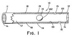
図1は、自浄式胆管ステントの例示的実施形態の部分断面斜視図である。自浄式ステント10は、第1の部分11と、第2の部分12と、全長を貫通するルーメン17とを備える。自浄式ステント10の壁18は約0.508ミリメートル(0.020インチ)厚であり、自浄式ステント10の外径は約3〜10フレンチである。しかしながら、患者のニーズ、重みの付いた物体13のサイズ、及び自浄式ステント10が留置される体管腔の直径によっては他のサイズが企図される。壁18の中に含まれる側部排液ポート15によってさらなる流体が通過できるようになる。側部排液ポート15は組織と接触しないように構成され得る。例えば側部排液ポート15は壁18の第2の部分12又は第1の部分11の近傍に設けることができ、ここで壁18のかかる部分は自浄式ステント10が留置される生体組織のいかなる部分とも接触しない。例えば、側部排液ポート15を伴い構成された第2の部分12は十二指腸内まで伸張でき、このとき側部排液ポート15はいかなる組織とも接触せず、従っていかなる組織によっても詰まることがない。 FIG. 1 is a partial cross-sectional perspective view of an exemplary embodiment of a self-cleaning biliary stent. The self-cleaning
自浄式ステント10内には重みの付いた物体13が含まれ、これはルーメン17を自在に動き回ることができる。重みの付いた物体13は、セラミック、ステンレス鋼、又は金で作製される。しかしながら、他の医学的に許容可能な材料もまた企図され、限定はされないが、極めて不活性で高密度の材料が挙げられる。重みの付いた物体13は、患者の動作、流体の流動、及び/又は重力の変化に応じてルーメン17内を長手方向に移動する。重みの付いた物体13が移動すると、重みの付いた物体13は壁18の内表面101と接触し、そのためそこに付着している任意の蓄積性物質が除去される。次に蓄積性物質は自浄式ステント10の第1の部分11又は第2の部分12を通じて出る。蓄積性物質はまた側部排液ポート15からも出ることができる。重みの付いた物体13は好ましくは5〜10グラムであるが、他の質量も企図される。重みの付いた物体13は十分な大きさ及び形状として、重みの付いた物体13が流体の流動を完全に塞ぐことのないよう、且つステント10をその留置箇所から脱離させることなく重みの付いた物体13がルーメン17を動き回ることのできるようにしなければならない。重みの付いた物体13の形状は円形に限定されず、他の形状が企図され、限定はされないが、四角形、矩形、円筒形、又は三角形のものが挙げられる。加えて、重みの付いた物体13には追加的な材料又はコーティングを被着させて蓄積性物質の除去を補助してもよい。 The self-cleaning
自浄式ステント10は2つの端部キャップ拘束機構14も備え(図2にも図示される)、これは壁18の一部として押し出されているが、端部キャップ14は自浄式ステント10の第1の部分11及び第2の部分12に固定して取り付けられる別個の部品であり得ることも企図される。加えて、端部キャップ14は自浄式ステント10の壁18の中に設置され得ることが企図される。端部キャップ14は重みの付いた物体13がルーメン17から脱出するのを防止し、且つ開口16を有して流体の通過を可能にする。端部キャップ14は十字形に限定されず、重みの付いた物体13のルーメン17からの脱出を防止し、且つ流体を通過させることのできる他の形状を挙げることもできる。 The self-cleaning
壁18は、任意の好適な生体適合性材料及び生体安定性材料で形成され得る。壁18は好ましくは、十分な弾性を有して適合することで、それが留置される管路の曲率に容易に従う一方、十分な「フープ」強度を有することで、その形状を管路内で保持する。自浄式ステント10の壁18は好ましくは中密度生体適合性ポリエチレンで作製されるが、他の材料も企図され、限定はされないが、ポリウレタン、ポリテトラフルオロエチレン(PTFE)、ステンレス鋼、及びニチノールが挙げられる。一態様において、壁18は、ポリオレフィン、例えば、メタロセン触媒ポリエチレン、ポリプロピレン、ポリブチレン又はこれらの共重合体などで形成される。壁18の他の好適な材料としては、ポリウレタン(商標PELLETHANEとしてダウ・コーニング(Dow Corning)から市販されている材料など);シリコンゴム(商標SILASTICとしてダウ・コーニング(Dow Corning)から市販されている材料など);ポリエーテルエーテルケトン(商標PEEKとしてビクトレックス(Victrex)から市販されている材料など);ポリスチレンなどのビニル芳香族ポリマー;スチレン−イソブチレン共重合体及びブタジエン−スチレン共重合体などのビニル芳香族共重合体;一部の酸性基が亜鉛イオン又はナトリウムイオンのいずれかで中和されている(一般にイオノマーとして知られる)酢酸エチレンビニル(EVA)、エチレン−メタクリル酸及びエチレン−アクリル酸共重合体などのエチレン共重合体;ポリアセタール類;ポリ塩化ビニル(PVC)などのクロロポリマー類;ポリエチレンテレフタレート(PET)などのポリエステル類;ポリエステル−エーテル類;ナイロン6及びナイロン6,6などのポリアミド類;ポリアミドエーテル類;ポリエーテル類;弾性ポリウレタン類及びポリウレタン共重合体などのエラストマー類;シリコーン類;ポリカーボネート類;並びに前述のいずれかの混合物及びブロック共重合体又はランダム共重合体が挙げられる。 The
自浄式ステント10の表面はポリマーで被膜され得る。壁18は、その外表面19及びその内表面101の双方の上にポリマーコーティングを有するものとして例示されている。重みの付いた物体13は、その外表面102上にポリマーコーティングを有するものとして例示されている。外表面19、102及び内表面101上のポリマーコーティングは生体適合性ポリマーであってもよく、限定はされないがPTFEが挙げられる。ポリマーコーティングはまた、ポリアクリレート、アクリル酸を含んでなる共重合体、ポリメタクリレート、ポリアクリルアミド、ポリ(ビニルアルコール)、ポリ(エチレンオキシド)、ポリ(エチレンイミン)、カルボキシメチルセルロース、メチルセルロース、ポリ(アクリルアミドスルホン酸)、ポリアクリロニトリル、ポリ(ビニルピロリドン)、寒天、デキストラン、デキストリン、カラギーナン、キサンタン、及びグアーからなる群から選択される親水性ポリマーを含んでなることもできる。親水性ポリマーはまた、酸性基、例えば、カルボン酸基、スルホン酸基又は硝酸基などのイオン性基も含み得る。親水性ポリマーは好適な架橋結合化合物により架橋されてもよい。実際に使用される架橋結合剤は、ポリマー系に依存する。ポリマー系が遊離基重合として重合される場合、好ましい架橋結合剤は2つ又は3つの不飽和二重結合を含んでなる。 The surface of the self-cleaning
内表面101及び外表面19、102上のポリマーコーティングはまた、様々な生物活性剤を取り込むこともできる。生物活性剤としては好ましくは、1つ又は複数の抗菌剤が挙げられる。用語「抗菌剤」は、微生物、例えば、細菌、病原菌、真菌、ウイルス、胞子、酵母、カビ、及び他の一般的に感染症と関連する、例えば、本明細書に記載される医療用具の使用によって感染するものなどの抑制、予防又はそれらからの保護に有効な生物活性剤を指す。抗菌剤としては、抗生物質薬及び抗真菌薬が挙げられる。 The polymer coating on the
抗生物質薬としては、セファロスポリン類、クリンダマイシン、クロラムフェニコール、カルバペネム類、ペニシリン類、モノバクタム類、キノロン類、テトラサイクリン、マクロライド類、サルファ系抗生物質、トリメトプリム、フシジン酸及びアミノグリコシド類を挙げることができる。抗真菌薬としては、アムホテリシンB、アゾール類、フルシトシン、シロフンギン(cilofungin)及びニッコーマイシンZを挙げることができる。好適な抗生物質薬の具体的な非限定例としては、シプロフロキサシン、ドキシサイクリン、アモキシシリン、メトロニダゾール、ノルフロキサシン(場合によりウルソデオキシコール酸と併用して)、セフタジジム(ciftazidime)、及びセフォキシチンが挙げられる。他の好適な抗生物質薬としては、参照により全体として本明細書に援用される米国特許第5,217,493号(ラド(Raad)など)において考察されるリファンピン、ミノサイクリン、ノボビオシン及びこれらの組み合わせが挙げられる。リファンピンは、カビのストレプトマイセス・メディテラニク(Streptomyces mediterranic)により産生される大環状抗生物質化合物であるリファマイシンBの半合成誘導体である。リファンピンは細菌のDNA依存性RNAポリメラーゼ活性を阻害すると考えられ、本質的に殺菌性を有する。リファンピンは米国ではメリル・ダウ・ファーマシューティカルズ(Merrill Dow Pharmaceuticals)、オハイオ州シンシナティ(Cincinnati,Ohio)から入手可能である。ミノサイクリンは、テトラサイクリン由来の半合成抗生物質である。これは主として静菌性を有し、タンパク質合成を阻害することにより抗菌効果を呈すると考えられる。ミノサイクリンは塩酸塩として市販されており、黄色の結晶性粉末として存在するもので、水に対し可溶性であり、アルコールに対しても僅かに可溶性である。ミノサイクリンは、レダール・ラボラトリーズ・ディビジョン(Lederle Laboratories Division)、アメリカン・サイアナミッド社(American Cyanamid Company)、ニューヨーク州パール・リバー(Pearl River)から入手可能である。ノボビオシンは、ストレプトマイセス・ニベウス(Streptomyces niveus)又はS.スフェロイデス(S.spheroides)の培養物から得られる抗生物質である。ノボビオシンは通常、活性の点で静菌性であり、細菌細胞壁の合成を妨害し、細菌タンパク質及び核酸合成を阻害すると考えられる。ノボビオシンはまた、マグネシウムと錯体を形成することにより細胞膜の安定性にも影響を及ぼすものと思われる。ノボビオシンは、アップジョン社(Upjohn Company)、ミシガン州カラマズー(Kalamazoo,Michigan)から入手可能である。 Antibiotics include cephalosporins, clindamycin, chloramphenicol, carbapenems, penicillins, monobactams, quinolones, tetracyclines, macrolides, sulfa antibiotics, trimethoprim, fusidic acid and aminoglycosides Can be mentioned. Antifungal agents include amphotericin B, azoles, flucytosine, silofungin and nikkomycin Z. Specific non-limiting examples of suitable antibiotic drugs include ciprofloxacin, doxycycline, amoxicillin, metronidazole, norfloxacin (optionally in combination with ursodeoxycholic acid), ceftazidime, and cefoxitin . Other suitable antibiotic drugs include rifampin, minocycline, novobiocin and combinations thereof discussed in US Pat. No. 5,217,493 (such as Raad), which is incorporated herein by reference in its entirety. Is mentioned. Rifampin is a semi-synthetic derivative of rifamycin B, a macrocyclic antibiotic compound produced by the mold Streptomyces mediterranic. Rifampin is believed to inhibit bacterial DNA-dependent RNA polymerase activity and is essentially bactericidal. Rifampin is available in the United States from Merrill Dow Pharmaceuticals, Cincinnati, Ohio. Minocycline is a semisynthetic antibiotic derived from tetracycline. This is mainly bacteriostatic and is considered to exhibit an antibacterial effect by inhibiting protein synthesis. Minocycline is commercially available as the hydrochloride salt and exists as a yellow crystalline powder that is soluble in water and slightly soluble in alcohol. Minocycline is available from Lederle Laboratories Division, American Cyanamid Company, Pearl River, NY. Novobiocin is available from Streptomyces niveus or S. cerevisiae. It is an antibiotic obtained from a culture of S. spheroides. Novobiocin is usually bacteriostatic in activity and is thought to interfere with bacterial cell wall synthesis and inhibit bacterial protein and nucleic acid synthesis. Novobiocin may also affect cell membrane stability by forming a complex with magnesium. Novobiocin is available from Upjohn Company, Kalamazoo, Michigan.
ポリマーコーティングは、所定時間および所定の速度で生物活性剤を体内に放出することが可能であることが好ましい。かかるポリマーコーティングは、米国特許第5,380,299号、米国特許第6,530,951号、米国特許第6,774,278号及び米国特許出願第10/218,305号、米国特許出願第10/223,415号、米国特許出願第10/410,587号、米国特許出願第10/000,659号、及び米国特許出願第10/618,977号に記載される薬物溶出性マトリクス材料を含み、これらの文献の全ては参照することにより全体として本明細書の一部とされる。 The polymer coating is preferably capable of releasing the bioactive agent into the body for a predetermined time and at a predetermined rate. Such polymer coatings are described in U.S. Patent No. 5,380,299, U.S. Patent No. 6,530,951, U.S. Patent No. 6,774,278 and U.S. Patent Application No. 10 / 218,305, U.S. Patent Application No. The drug-eluting matrix materials described in US patent application Ser. No. 10 / 223,415, US patent application Ser. No. 10 / 410,587, US patent application Ser. No. 10 / 000,659, and US patent application Ser. No. 10 / 618,977. All of which are hereby incorporated by reference in their entirety.
あるいは、外表面19、102及び内表面101上には種々のポリマーコーティングが被膜され得る。例えば、外表面19上のポリマーコーティングとしては、自浄式ステント10が長時間患者の通路と接触する結果として生じる組織への刺激作用を低減する働きをする、当業者に一般に知られている任意のポリマーコーティングを挙げることができる。内表面101及び外表面102上のポリマーコーティングとしてはまた、さらに自浄式ステント10の詰まりを防ぐ働きをする、当業者に一般に知られている任意のコーティングも挙げることができる。 Alternatively, various polymer coatings can be coated on the
あるいは、自浄式ステント10の内表面101及び外表面19、102は、時間の経過に伴い徐々に生体内で分解する生分解性ポリマーで構成され得る。生分解性ポリマーとしては、ポリ(乳酸d))、ポリ(グリコール酸)、及びポリ−ε−カプロ−ラクトン、又はこれらの組み合わせなどの剛性で溶解可能なポリマーを挙げることができる。他の剛性で溶解可能なポリマーは、当業者には明らかであろう。好適な生分解性ポリマーは、ヒドロゲル、エラスチン様ペプチド、ポリヒドロキシアルカノエート(PHA)類、ポリヒドロキシブチラート化合物、並びにこれらの共重合体及び混合物からなる群から選択され得る。生分解性材料は様々な設計基準に基づき選択でき、且つ異なり得る。生分解性材料は好ましくは、エステルなどの1つ又は複数の加水分解性の化学結合、所望の架橋結合度、不均一分解が最小限の分解機序、及び非毒性の単量体を含んでなる。生分解性材料は好ましくは、ポリヒドロキシアルカノエート化合物、ヒドロゲル、ポリ(グリセロール−セバケート)又はエラスチン様ペプチドである。望ましくは、生分解性材料はポリ−α−ヒドロキシ酸、例えば、ポリ乳酸(PLA)を含んでなる。PLAは、典型的にはポリ−D,L−乳酸と称される鏡像異性体の混合物であり得る。あるいは、生分解性材料はポリ−L(+)−乳酸(PLLA)又はポリ−D(−)−乳酸(PDLA)であり、これらは生分解速度が互いに異なる。PLLAは半結晶性である。対照的に、PDLAは非晶質であり、これは活性種の均一な分散を促進できる。特記されない限り、本明細書における「PLA」への言及は、PLA、PLLA及びPDLAからなる群から選択される生分解性ポリマーを指す。 Alternatively, the
薬物放出コーティングを含んでなる自浄式ステント10が、熱可塑性材料及びエラストマー材料などのポリマー材料を付形するために従来から使用されている任意の好適なプロセスにより形成され得る。付形プロセスとしては、限定はされないが、共押出しを含む押出し、成形、カレンダリング、鋳造及び溶媒コーティングを挙げることができる。好ましい付形プロセスとしては、押出し及び共押出しプロセスが挙げられる。例えば、生分解性ポリマーの溶媒溶液又は液状分散体を壁18の表面上に塗布し、続いて溶媒又は液状分散剤を、例えば蒸発によって除去することにより、薬物と混合された生分解性コーティングポリマーが自浄式ステント10の内表面101に塗布され得る。かかる生分解性ポリマーの溶液又は分散体は、支持部材の表面を、例えば浸漬又は噴霧によって溶液又は分散体と接触させることにより塗布され得る。例えば、生分解性コーティングは、生分解性ポリマーの溶液を自浄式ステント10のルーメン内の壁18に噴霧することにより塗布され得る。あるいは、被膜された自浄式ステント10は、生分解性コーティングの外表面にポリマーを塗布することにより形成すると、多層医療器具を形成できる。例えば、生体安定性ポリマーの溶液を生分解性コーティングのチューブの外側表面に塗布して適所で乾燥させることにより、自浄式ステント10を形成できる。 Self-cleaning
あるいは、複数の層のそれぞれを溶媒キャスト(solvent cast)することもできる。第2の層が、既にキャストされた層は溶解しない溶媒からキャストされる。例えば、自浄式ステント10を形成するために使用されるポリウレタンはジメチルホルムアミド中に溶解し得る一方、生分解性コーティングを形成するために使用されるPLAはジクロロメタン中に溶解し得る。第2の溶媒が支持部材のポリマーを溶解しない場所では、第2の溶液は、乾燥されて溶媒が蒸散すると、第1の層の上に薄く広がり得る。得られる多層は層間の結合が強い。 Alternatively, each of the plurality of layers can be solvent cast. The second layer is cast from a solvent that does not dissolve the already cast layer. For example, the polyurethane used to form the self-cleaning
生体内沈着を低減する生物活性剤は、押出し温度に耐えるように選択され得る。第1の態様において、生物活性剤は押出し前にポリマー中に取り込まれてもよく、又はポリマーと混合されてもよい。フィルムの押出しにより、押出し温度に耐えることのできる薬物又は薬剤を取り込むことができる。例えば、参照により全体として本明細書に援用される米国特許出願公開第2005/0008763A1号に記載された抗菌剤が、この製造技法に適合する。生物活性剤は好ましくは、それが取り込まれる生分解性材料の物理的又は化学的特性を実質的に妨害しない。生物活性剤及び生分解性材料は、予成形のための当該技術分野において周知の任意の従来式装置を使用して予成形され得る。熱可塑性材料が用いられる場合、ポリマー溶融物は様々な薬剤を加熱し、次にそれらを混合して均質な混合物を形成することにより形成されてもよい。これを行うための一般的な方法は、マトリクスポリマーと添加剤との混合物に機械的剪断を加えることである。このようにして生分解性材料と生物活性剤とが混合され得る装置としては、限定はされないが、一軸スクリュー押出し機、二軸スクリュー押出し機、バンベリーミキサー、高速ミキサー、及びロスケトル(ross kettle)などの装置が挙げられる。 Bioactive agents that reduce in vivo deposition can be selected to withstand extrusion temperatures. In the first aspect, the bioactive agent may be incorporated into the polymer prior to extrusion or may be mixed with the polymer. Film extrusion can incorporate drugs or agents that can withstand the extrusion temperature. For example, the antimicrobial agents described in US Patent Application Publication No. 2005 / 0008763A1, incorporated herein by reference in its entirety, are compatible with this manufacturing technique. The bioactive agent preferably does not substantially interfere with the physical or chemical properties of the biodegradable material into which it is incorporated. The bioactive agent and biodegradable material can be preformed using any conventional device known in the art for preforming. If a thermoplastic material is used, the polymer melt may be formed by heating the various agents and then mixing them to form a homogeneous mixture. A common way to do this is to apply mechanical shear to the mixture of matrix polymer and additive. The apparatus in which the biodegradable material and the bioactive agent can be mixed in this way is not limited, but includes a single screw extruder, a twin screw extruder, a banbury mixer, a high-speed mixer, a loss kettle, and the like. Apparatus.
第2の態様において、生分解性コーティングは生物活性剤を含まず自浄式ステント10に付着させ、続いて器具の形成後に生物活性剤を生分解性コーティング中に吸収させてもよい。例えば、生分解性コーティングは自浄式ステント10の排液ルーメン内で生物活性剤の溶液と接触させ得る。溶液中の生物活性剤の有効濃度は、ミノサイクリンについて約1〜10μg/ml、好ましくは約2μg/ml;リファンピンについて1〜10μg/ml、好ましくは約2μg/ml;及びノボビオシンについて1〜10μg/ml、好ましくは約2μg/mlの範囲であり得る。溶液は好ましくは滅菌水又は無菌生理食塩水からなる。 In a second embodiment, the biodegradable coating may be attached to the self-cleaning
図3は、自浄式ステントの代替的な例示的実施形態を図示する。自浄式ステント20は端部キャップ拘束機構24(図4にも図示される)を備え、これは壁18の一部として押し出されているが、端部キャップ24は自浄式ステント20の第1の部分21及び第2の部分22に固定して取り付けられる別個の部品であり得ることも企図される。加えて、端部キャップ24は自浄式ステント20の壁18の中に設置され得ることが企図される。端部キャップ24は重みの付いた物体26の脱出を防ぐとともに、開口25を提供して流体がルーメン23を通過できるようにする。端部キャップ24は斜線形状に限定されず、重みの付いた物体26のルーメン23からの脱出を防止し、且つ流体を通過させることのできる他の形状を挙げることもできる。 FIG. 3 illustrates an alternative exemplary embodiment of a self-cleaning stent. The self-cleaning
ルーメン23内には、種々のサイズの複数の重みの付いた物体26がある。重みの付いた物体26はルーメン23内を自在に動き回ることができる。患者の動作、流体の流動、及び/又は重力の変化に応じて重みの付いた物体26は移動し、互いに、及び壁18の内表面101と接触して、そこに付着した蓄積性物質を除去する。重みの付いた物体26は円形のものとして図示されているが、様々な異なる形状を有することができ、限定はされないが、四角形、矩形、円筒形、又は三角形が挙げられる。加えて、特定の重みの付いた物体26が別の重みの付いた物体26と異なる形状、サイズ、及びコーティング102を有してもよい。加えて、重みの付いた物体26にさらなる材料又はコーティングを被着させることで蓄積性物質の除去を補助し得る。 Within lumen 23 is a plurality of
図5は、自浄式胆管ステントの別の例示的実施形態を図示する。重みの付いた物体36が線35により接続点拘束機構34を介して第1の部分31に接続される。線35はステンレス鋼製の編組ケーブルである。しかしながら他の構成も企図され、限定はされないが、プラスチック線及びナイロン線が挙げられる。線35は、重みの付いた物体36が第2の部分32の方に向かって移動できる距離を制限する。従って、自浄式ステント30の第2の部分32を部分的に塞ぐ必要はない。加えて、線35は重みの付いた物体36の重心からずらして重みの付いた物体36と接続され得る。加えて、重みの付いた物体36は、その重心が重みの付いた物体36の中心に直接位置しないように構成され得る。ひいては重みの付いた物体36がルーメン33をさらに動き回りやすくなる。 FIG. 5 illustrates another exemplary embodiment of a self-cleaning biliary stent. The
重みの付いた物体36は自浄式ステント30のルーメン33の中を、患者の動作、流体の流動、及び/又は重力の変化に応じて移動する。重みの付いた物体36がルーメン33を動き回ると、重みの付いた物体36は壁18の内表面101と接触するため、そこに付着している蓄積性物質が除去される。重みの付いた物体36の形状は円筒形に限定されない。他の形状が企図され、限定はされないが、四角形、矩形、円形、又は三角形のものが挙げられる。加えて、重みの付いた物体36にさらなる材料又はコーティングを被着させることで蓄積性物質の除去を補助し得る。 The
加えて、線35は、重みの付いた物体36が伸張してステント30から出ることにより振り子として作用するよう構成され得る。これにより線35は壁18の内表面101を擦過し、そこに付着している蓄積性物質を除去し得る。かかる構成は自浄式ステント30が十二指腸で使用される場合に有利となり得、ここでは第2の部分32が十二指腸内まで伸張し、重みの付いた物体36が十二指腸内に吊るされる振り子として作用するよう構成される。 In addition, the
図6は自浄式ステントの別の例示的実施形態を図示する。接続点拘束機構43が自浄式ステント40の第1の部分41及び第2の部分42に位置する。接続点43には線44が取り付けられ、線44は重みの付いた物体46のルーメン48に挿通されているため、重みの付いた物体46は線44に沿って自在に摺動する。重みの付いた物体46は、患者の動作、流体の流動、及び/又は重力の変化に応じて自浄式ステント40のルーメン45内を移動する。接続点43が重みの付いた物体46の移動をルーメン45内部に制限するが、線44は弛みを有するため、重みの付いた物体46は壁18の内表面101に接触できる。重みの付いた物体46がルーメン45を動き回ると、ブリスル47が壁18の内表面101に接触するため、そこに付着している蓄積性物質が除去される。重みの付いた物体46の形状は円形に限定されず、他の形状が企図され、限定はされないが、矩形、四角形、円筒形、又は三角形のものが挙げられる。さらに、重みの付いた物体46は三角形のブリスル47に限定されず、他の形状が企図され、限定はされないが、四角形、円筒形、矩形、又は円形のものが挙げられる。加えて、サイズ、形状、又はコーティング102が同じか、又は異なるさらなる重みの付いた物体が線44に沿って追加され得ることが企図される。加えて、2本以上の摺動線44がルーメン45内に含まれ得ることがさらに企図され、ここで各線には少なくとも1つの重みの付いた物体が取り付けられている。加えて、重みの付いた物体46にコーティング102を被着させることで蓄積性物質の除去を補助し得る。 FIG. 6 illustrates another exemplary embodiment of a self-cleaning stent. A connection
図7は自浄式ステントのさらに別の実施形態を図示する。自浄式ステント50は、流体が通過できるような全長を貫通するルーメン53を有する。自浄式ステント50の第1の部分51及び第2の部分52は重みの付いた物体54の外径より小さい内径55を有し、それにより重みの付いた物体54を自浄式ステント50内に拘束する。加えて、プロング56により、重みの付いた物体54が第1の部分51又は第2の部分52に位置する内径55を閉塞することが防止される。1つのみの重みの付いた物体が図示されているが、図7に図示される重みの付いた物体と異なるサイズ、形状、又はコーティングを有するものを含め、複数の重みの付いた物体が使用され得ることも企図される。加えて、重みの付いた物体54にさらなる材料又はコーティングを被着させることで蓄積性物質の除去を補助し得る。 FIG. 7 illustrates yet another embodiment of a self-cleaning stent. The self-cleaning
図8は、側部排液ポート15を有する自浄式ステントのさらに別の実施形態を図示する。自浄式ステント60の第1の部分61には接続点拘束機構63が位置し、そこにつる巻ばね65が接続される。ばね65はまた、重みの付いた物体67とも接続される。ばねは第1の部分61に向かって付勢されており、患者の動作、流体の流動、及び/又は重力の変化に応じて重みの付いた物体67が一時的にばね65を伸張することにより、重みの付いた物体67がルーメン64内を長手方向に第2の部分62に向かって移動し得る。患者の動作、流体の流動、及び/又は重力の変化がそれ以上存在しなくなると、ばね65は縮み、重みの付いた物体67が第1の部分61に向かって引っ張られる。好ましくは、ばね定数を最小とし、且つ重みの付いた物体67の質量を最大として、重みの付いた物体67が容易に移動できるようにする。重みの付いた物体67がルーメン64内を移動すると、重みの付いた物体67が壁18の内表面101に接触してそこに付着している蓄積性物質を除去する。加えて、重みの付いた物体67にさらなる材料又はコーティングを被着させることで蓄積性物質の除去を補助し得る。 FIG. 8 illustrates yet another embodiment of a self-cleaning stent having
前述の説明及び図面は例示目的で提供されるに過ぎず、本明細書に記載される、又はその構造及び動作方法の詳細に関する本発明の範囲を限定することは意図されない。本発明の趣旨及び範囲から逸脱することなく改変及び変形が加えられ得ることは当業者に明らかであろう。状況が示唆し、且つ好都合となる場合には、形態及び部品の比率の変更、並びに等価物の代用が企図される。具体的な用語が用いられているが、用語は一般的で説明的な意味に過ぎず、以下の特許請求の範囲に記載される本発明の範囲を限定する目的はないことが意図される。 The foregoing description and drawings are provided by way of example only and are not intended to limit the scope of the invention as described herein or with regard to details of its structure and method of operation. It will be apparent to those skilled in the art that modifications and variations can be made without departing from the spirit and scope of the invention. Where the circumstances suggest and expedient, changes in form and part ratios, and substitution of equivalents are contemplated. Although specific terms are employed, the terms are intended to be general and descriptive only and are not intended to limit the scope of the invention as set forth in the following claims.
Claims (20)
Translated fromJapanese第1の部分と、第2の部分と、全長を貫通するルーメンとを有する細長チューブ状本体と、
前記細長チューブ状本体に関して移動可能に配置される重みの付いた物体であって、前記細長チューブ状本体内に堆積した蓄積性物質を少なくとも部分的に除去して前記細長チューブ状本体に通じる流路の維持を容易にするよう構成される重みの付いた物体と、
前記重みの付いた物体を前記細長チューブ状本体に関して拘束するよう構成される拘束機構と、
を備える、自浄式ステント。A self-cleaning stent,
An elongated tubular body having a first portion, a second portion, and a lumen extending through the entire length;
A weighted object movably disposed with respect to the elongate tubular body, the flow path leading to the elongate tubular body by at least partially removing accumulative material deposited in the elongate tubular body A weighted object configured to facilitate maintenance, and
A restraining mechanism configured to restrain the weighted object with respect to the elongated tubular body;
A self-cleaning stent.
前記重みの付いた物体が前記線と摺動可能に取り付けられる、請求項1に記載の自浄式ステント。The self-cleaning of claim 1, wherein the self-cleaning stent further comprises a wire attached to the first portion and the second portion, and the weighted object is slidably attached to the wire. Stent.
第1の部分と、第2の部分と、全長を貫通するルーメンと、少なくとも1つの側部排液ポートとを有する細長チューブ状本体と、
前記細長チューブ状本体内に移動可能に配置された少なくとも1つの重みの付いた物体であって、前記細長チューブ状本体内に堆積した蓄積性物質を少なくとも部分的に除去して前記細長チューブ状本体に通じる流路の維持を促進するよう構成される重みの付いた物体と、
前記重みの付いた物体を前記細長チューブ状本体内に維持するための拘束機構と、
を備える、自浄式ステント。A self-cleaning stent,
An elongated tubular body having a first portion, a second portion, a lumen extending through the entire length, and at least one side drainage port;
At least one weighted object movably disposed within the elongate tubular body, wherein the accumulating material deposited in the elongate tubular body is at least partially removed to provide the elongate tubular body A weighted object configured to facilitate the maintenance of a flow path leading to
A restraining mechanism for maintaining the weighted object in the elongated tubular body;
A self-cleaning stent.
細長チューブ状本体と、前記細長チューブ状本体に関して移動可能に配置された少なくとも1つの重みの付いた物体とを有する自浄式ステントを提供するステップであって、前記重みの付いた物体が、患者の動作、流体の流動、及び重力の変化からなる群から選択される力に応じて、前記細長チューブ状本体内に堆積した蓄積性物質を少なくとも部分的に除去して前記細長チューブ状本体に通じる流路の維持を促進するよう構成される、ステップと、
前記自浄式ステントを患者の体内管腔に埋め込むステップと、
を含む、方法。A method for preventing occlusion of a stent, comprising:
Providing a self-cleaning stent having an elongate tubular body and at least one weighted object movably disposed with respect to the elongate tubular body, wherein the weighted object comprises: A flow through the elongated tubular body to at least partially remove accumulating material deposited in the elongated tubular body in response to a force selected from the group consisting of motion, fluid flow, and gravity change. Steps configured to facilitate road maintenance;
Implanting the self-cleaning stent in a body lumen of a patient;
Including a method.
Applications Claiming Priority (2)
| Application Number | Priority Date | Filing Date | Title |
|---|---|---|---|
| US81564606P | 2006-06-22 | 2006-06-22 | |
| PCT/US2007/014214WO2007149404A2 (en) | 2006-06-22 | 2007-06-18 | Self-cleaning stent |
Publications (1)
| Publication Number | Publication Date |
|---|---|
| JP2009540926Atrue JP2009540926A (en) | 2009-11-26 |
Family
ID=38691679
Family Applications (1)
| Application Number | Title | Priority Date | Filing Date |
|---|---|---|---|
| JP2009516532AWithdrawnJP2009540926A (en) | 2006-06-22 | 2007-06-18 | Self-cleaning stent |
Country Status (7)
| Country | Link |
|---|---|
| US (1) | US8864842B2 (en) |
| EP (1) | EP2032089B1 (en) |
| JP (1) | JP2009540926A (en) |
| AT (1) | ATE522190T1 (en) |
| AU (1) | AU2007261513B2 (en) |
| CA (1) | CA2659735C (en) |
| WO (1) | WO2007149404A2 (en) |
Families Citing this family (10)
| Publication number | Priority date | Publication date | Assignee | Title |
|---|---|---|---|---|
| US7377939B2 (en)* | 2003-11-19 | 2008-05-27 | Synecor, Llc | Highly convertible endolumenal prostheses and methods of manufacture |
| US20090192588A1 (en)* | 2008-01-29 | 2009-07-30 | Taeoong Medical Co., Ltd | Biodegradable double stent |
| US20100042202A1 (en)* | 2008-08-13 | 2010-02-18 | Kamal Ramzipoor | Composite stent having multi-axial flexibility |
| EP2413839B1 (en)* | 2009-04-02 | 2014-05-07 | Cook Medical Technologies LLC | System and method for maintaining patency of a stent using a magnet |
| CN109125893A (en) | 2013-02-28 | 2019-01-04 | 波士顿科学国际有限公司 | Medical devices used along the biliary and/or pancreatic ducts |
| US20200188147A1 (en)* | 2018-12-14 | 2020-06-18 | Drexel University | Geometrically tunable hydrogel-based chemically-eluting shunt prosthesis |
| EP3908233B1 (en) | 2019-01-07 | 2024-08-21 | Boston Scientific Scimed, Inc. | Stent with anti-migration feature |
| CA3195219A1 (en) | 2020-09-29 | 2022-04-07 | Boston Scientific Scimed, Inc. | Stent with anti-migration features |
| CA3202580A1 (en) | 2020-12-02 | 2022-06-09 | Boston Scientific Scimed, Inc. | Stent with improved deployment characteristics |
| CN113081416B (en)* | 2021-02-25 | 2024-07-12 | 中国人民解放军北部战区总医院 | Urinary system support |
Family Cites Families (42)
| Publication number | Priority date | Publication date | Assignee | Title |
|---|---|---|---|---|
| US1889705A (en)* | 1931-03-16 | 1932-11-29 | Carroll P Sherwood | Flow meter |
| GB1165698A (en)* | 1965-11-05 | 1969-10-01 | Guinness De Laszlo M A P Henry | Improvements in or relating to Prostheses |
| US4479796A (en)* | 1982-11-15 | 1984-10-30 | Medtronic, Inc. | Self-regenerating drug administration device |
| US4699611A (en)* | 1985-04-19 | 1987-10-13 | C. R. Bard, Inc. | Biliary stent introducer |
| US5782792A (en)* | 1986-11-21 | 1998-07-21 | Cypress Bioscience, Inc. | Method for treatment of rheumatoid arthritis |
| US5240601A (en)* | 1988-11-09 | 1993-08-31 | Chembiomed, Ltd. | Affinity supports for hemoperfusion |
| IL89297A0 (en) | 1989-02-15 | 1989-09-10 | Technion Res & Dev Foundation | Auxilary intra-urethral magnetic valve for persons suffering from urinary incontinence |
| US5397351A (en)* | 1991-05-13 | 1995-03-14 | Pavcnik; Dusan | Prosthetic valve for percutaneous insertion |
| US5798697A (en)* | 1991-09-24 | 1998-08-25 | Wiseman; Brian | Exhaust/supply direction indicator |
| US5291182A (en)* | 1991-09-24 | 1994-03-01 | Brian Wiseman | Fluid flow direction detector |
| US5661461A (en)* | 1991-09-24 | 1997-08-26 | Wiseman; Brian | Exhaust/supply direction indicator |
| US5217493A (en) | 1992-03-11 | 1993-06-08 | Board Of Regents, The University Of Texas System | Antibacterial coated medical implants |
| US5380299A (en) | 1993-08-30 | 1995-01-10 | Med Institute, Inc. | Thrombolytic treated intravascular medical device |
| US7611533B2 (en) | 1995-06-07 | 2009-11-03 | Cook Incorporated | Coated implantable medical device |
| US7550005B2 (en) | 1995-06-07 | 2009-06-23 | Cook Incorporated | Coated implantable medical device |
| US6774278B1 (en) | 1995-06-07 | 2004-08-10 | Cook Incorporated | Coated implantable medical device |
| US5647843A (en) | 1996-05-24 | 1997-07-15 | Vance Products Incorporated | Anti-reflux ureteral stent |
| US20040068241A1 (en) | 1996-06-04 | 2004-04-08 | Fischer Frank J. | Implantable medical device |
| US6530951B1 (en) | 1996-10-24 | 2003-03-11 | Cook Incorporated | Silver implantable medical device |
| EP0891752B1 (en)* | 1997-07-17 | 2005-01-12 | Schneider (Europe) GmbH | Stent and method for manufacturing such a stent |
| JP2002508209A (en)* | 1997-12-15 | 2002-03-19 | プロリフィックス メディカル, インコーポレイテッド | Vascular stent for reduction of restenosis |
| US6066088A (en)* | 1998-07-13 | 2000-05-23 | Phillip Davis Inventions, Inc. | Intraurethral magnetic valve |
| US6746489B2 (en) | 1998-08-31 | 2004-06-08 | Wilson-Cook Medical Incorporated | Prosthesis having a sleeve valve |
| CA2338518C (en) | 1998-08-31 | 2007-09-25 | Wilson-Cook Medical Inc. | Anti-reflux esophageal prosthesis |
| DE19948783C2 (en)* | 1999-02-18 | 2001-06-13 | Alcove Surfaces Gmbh | Implant |
| US7175644B2 (en)* | 2001-02-14 | 2007-02-13 | Broncus Technologies, Inc. | Devices and methods for maintaining collateral channels in tissue |
| US20050060044A1 (en)* | 1999-08-05 | 2005-03-17 | Ed Roschak | Methods and devices for maintaining patency of surgically created channels in a body organ |
| US6419657B1 (en)* | 2000-08-22 | 2002-07-16 | Advanced Cardiovascular Systems, Inc. | Flow regulator valve to optimize stent deployment and method of using the same |
| US6475478B2 (en)* | 2000-08-24 | 2002-11-05 | Kaneka Corporation | Adsorbent, adsorbing and removing process and adsorber for endogenous cannabinoid |
| JP4283430B2 (en)* | 2000-09-26 | 2009-06-24 | 株式会社カネカ | Enterotoxin adsorbent, adsorption removal method and adsorber |
| WO2003026718A1 (en)* | 2000-10-31 | 2003-04-03 | Cook Incorporated | Coated implantable medical device |
| US6416540B1 (en)* | 2000-11-01 | 2002-07-09 | Sandip V. Mathur | Magnetically actuated cleanable stent and method |
| US6921378B2 (en)* | 2001-10-09 | 2005-07-26 | Boston Scientific Scimed, Inc. | Anti-reflux drainage devices and methods |
| US7993390B2 (en)* | 2002-02-08 | 2011-08-09 | Boston Scientific Scimed, Inc. | Implantable or insertable medical device resistant to microbial growth and biofilm formation |
| JP4277113B2 (en)* | 2002-02-27 | 2009-06-10 | 大同特殊鋼株式会社 | Ni-base alloy for heat-resistant springs |
| DK1521603T3 (en) | 2002-07-12 | 2011-04-18 | Cook Inc | Coated medical device |
| US20050008763A1 (en) | 2002-09-24 | 2005-01-13 | Schachter Steven C. | Antimicrobial coatings for medical applications |
| US6929664B2 (en)* | 2003-12-05 | 2005-08-16 | Fossa Medical, Inc. | Open lumen stents |
| AU2005208583A1 (en) | 2004-01-20 | 2005-08-11 | Massachusetts General Hospital | Permanent thrombus filtering stent |
| US20060089589A1 (en)* | 2004-10-21 | 2006-04-27 | Portnoy Harold D | Resistive shunt valve |
| WO2007127419A2 (en) | 2006-04-28 | 2007-11-08 | The Board Of Trustees Of The Leland Stanford Junior University | System and method to counter material deposition on devices in the urinary tract |
| US20080269546A1 (en) | 2007-04-24 | 2008-10-30 | David Wilkie | Self-acting urethral valve |
- 2007
- 2007-06-18JPJP2009516532Apatent/JP2009540926A/ennot_activeWithdrawn
- 2007-06-18CACA2659735Apatent/CA2659735C/ennot_activeExpired - Fee Related
- 2007-06-18USUS11/820,094patent/US8864842B2/enactiveActive
- 2007-06-18WOPCT/US2007/014214patent/WO2007149404A2/enactiveApplication Filing
- 2007-06-18ATAT07809644Tpatent/ATE522190T1/ennot_activeIP Right Cessation
- 2007-06-18AUAU2007261513Apatent/AU2007261513B2/ennot_activeCeased
- 2007-06-18EPEP07809644Apatent/EP2032089B1/ennot_activeNot-in-force
Also Published As
| Publication number | Publication date |
|---|---|
| AU2007261513A1 (en) | 2007-12-27 |
| US8864842B2 (en) | 2014-10-21 |
| WO2007149404A2 (en) | 2007-12-27 |
| US20070299506A1 (en) | 2007-12-27 |
| WO2007149404A3 (en) | 2008-02-14 |
| EP2032089B1 (en) | 2011-08-31 |
| ATE522190T1 (en) | 2011-09-15 |
| EP2032089A2 (en) | 2009-03-11 |
| CA2659735A1 (en) | 2007-12-27 |
| AU2007261513B2 (en) | 2013-06-13 |
| CA2659735C (en) | 2012-01-24 |
Similar Documents
| Publication | Publication Date | Title |
|---|---|---|
| JP2009540926A (en) | Self-cleaning stent | |
| AU2008293471B2 (en) | Medical implant having improved drug eluting features | |
| AU2007290217B2 (en) | Stent with antimicrobial drainage lumen surface | |
| US20080051911A1 (en) | Stent with antimicrobial drainage lumen surface | |
| US20080086214A1 (en) | Medical device having a sleeve valve with bioactive agent | |
| JP4846980B2 (en) | Method of manufacturing implantable or insertable medical device that inhibits microbial growth and biofilm formation | |
| US8740929B2 (en) | Spacing device for releasing active substances in the paranasal sinus | |
| US11357651B2 (en) | Stent assembly and method of preparing the stent assembly | |
| JP2010534086A (en) | Hypotube for intravascular drug delivery | |
| JP2006517850A (en) | Occlusion resistant hydrocephalus shunt | |
| RU2463009C2 (en) | Tube for enteral feeding | |
| CN110167610B (en) | Duct cover for implantable device | |
| Khan et al. | Drug-eluting ureteral stents: An overview | |
| EP2413839B1 (en) | System and method for maintaining patency of a stent using a magnet | |
| US20220105326A1 (en) | Extended release devices and therapeutics for long term treatment of urinary tract infection in-vivo |
Legal Events
| Date | Code | Title | Description |
|---|---|---|---|
| A300 | Application deemed to be withdrawn because no request for examination was validly filed | Free format text:JAPANESE INTERMEDIATE CODE: A300 Effective date:20100907 |