JP2009538693A - Cannula delivery instrument and method for a disposable infusion device - Google Patents
Cannula delivery instrument and method for a disposable infusion deviceDownload PDFInfo
- Publication number
- JP2009538693A JP2009538693AJP2009513211AJP2009513211AJP2009538693AJP 2009538693 AJP2009538693 AJP 2009538693AJP 2009513211 AJP2009513211 AJP 2009513211AJP 2009513211 AJP2009513211 AJP 2009513211AJP 2009538693 AJP2009538693 AJP 2009538693A
- Authority
- JP
- Japan
- Prior art keywords
- cannula
- needle
- driver
- patient
- skin
- Prior art date
- Legal status (The legal status is an assumption and is not a legal conclusion. Google has not performed a legal analysis and makes no representation as to the accuracy of the status listed.)
- Granted
Links
Images


Classifications
- A—HUMAN NECESSITIES
- A61—MEDICAL OR VETERINARY SCIENCE; HYGIENE
- A61M—DEVICES FOR INTRODUCING MEDIA INTO, OR ONTO, THE BODY; DEVICES FOR TRANSDUCING BODY MEDIA OR FOR TAKING MEDIA FROM THE BODY; DEVICES FOR PRODUCING OR ENDING SLEEP OR STUPOR
- A61M5/00—Devices for bringing media into the body in a subcutaneous, intra-vascular or intramuscular way; Accessories therefor, e.g. filling or cleaning devices, arm-rests
- A61M5/14—Infusion devices, e.g. infusing by gravity; Blood infusion; Accessories therefor
- A61M5/142—Pressure infusion, e.g. using pumps
- A61M5/14244—Pressure infusion, e.g. using pumps adapted to be carried by the patient, e.g. portable on the body
- A61M5/14248—Pressure infusion, e.g. using pumps adapted to be carried by the patient, e.g. portable on the body of the skin patch type
- A61M2005/14252—Pressure infusion, e.g. using pumps adapted to be carried by the patient, e.g. portable on the body of the skin patch type with needle insertion means
- A61M2005/14256—Pressure infusion, e.g. using pumps adapted to be carried by the patient, e.g. portable on the body of the skin patch type with needle insertion means with means for preventing access to the needle after use
- A—HUMAN NECESSITIES
- A61—MEDICAL OR VETERINARY SCIENCE; HYGIENE
- A61M—DEVICES FOR INTRODUCING MEDIA INTO, OR ONTO, THE BODY; DEVICES FOR TRANSDUCING BODY MEDIA OR FOR TAKING MEDIA FROM THE BODY; DEVICES FOR PRODUCING OR ENDING SLEEP OR STUPOR
- A61M5/00—Devices for bringing media into the body in a subcutaneous, intra-vascular or intramuscular way; Accessories therefor, e.g. filling or cleaning devices, arm-rests
- A61M5/14—Infusion devices, e.g. infusing by gravity; Blood infusion; Accessories therefor
- A61M5/158—Needles for infusions; Accessories therefor, e.g. for inserting infusion needles, or for holding them on the body
- A61M2005/1585—Needle inserters
- A—HUMAN NECESSITIES
- A61—MEDICAL OR VETERINARY SCIENCE; HYGIENE
- A61M—DEVICES FOR INTRODUCING MEDIA INTO, OR ONTO, THE BODY; DEVICES FOR TRANSDUCING BODY MEDIA OR FOR TAKING MEDIA FROM THE BODY; DEVICES FOR PRODUCING OR ENDING SLEEP OR STUPOR
- A61M2209/00—Ancillary equipment
- A61M2209/04—Tools for specific apparatus
- A61M2209/045—Tools for specific apparatus for filling, e.g. for filling reservoirs
- A—HUMAN NECESSITIES
- A61—MEDICAL OR VETERINARY SCIENCE; HYGIENE
- A61M—DEVICES FOR INTRODUCING MEDIA INTO, OR ONTO, THE BODY; DEVICES FOR TRANSDUCING BODY MEDIA OR FOR TAKING MEDIA FROM THE BODY; DEVICES FOR PRODUCING OR ENDING SLEEP OR STUPOR
- A61M5/00—Devices for bringing media into the body in a subcutaneous, intra-vascular or intramuscular way; Accessories therefor, e.g. filling or cleaning devices, arm-rests
- A61M5/14—Infusion devices, e.g. infusing by gravity; Blood infusion; Accessories therefor
- A61M5/142—Pressure infusion, e.g. using pumps
- A61M5/145—Pressure infusion, e.g. using pumps using pressurised reservoirs, e.g. pressurised by means of pistons
- A61M5/148—Pressure infusion, e.g. using pumps using pressurised reservoirs, e.g. pressurised by means of pistons flexible, e.g. independent bags
- A61M5/152—Pressure infusion, e.g. using pumps using pressurised reservoirs, e.g. pressurised by means of pistons flexible, e.g. independent bags pressurised by contraction of elastic reservoirs
Landscapes
- Health & Medical Sciences (AREA)
- Dermatology (AREA)
- Vascular Medicine (AREA)
- Engineering & Computer Science (AREA)
- Anesthesiology (AREA)
- Biomedical Technology (AREA)
- Heart & Thoracic Surgery (AREA)
- Hematology (AREA)
- Life Sciences & Earth Sciences (AREA)
- Animal Behavior & Ethology (AREA)
- General Health & Medical Sciences (AREA)
- Public Health (AREA)
- Veterinary Medicine (AREA)
- Infusion, Injection, And Reservoir Apparatuses (AREA)
Abstract
Translated fromJapaneseDescription
Translated fromJapanese本願は、2006年5月31日に提出されている米国特許仮出願第60/809,957号、及び、2006年12月18日に提出されている米国実用新案登録出願第11/641,596号の優先権を主張する。これらの文献が両方とも参照により組み込まれる。 The present application is related to US Provisional Patent Application No. 60 / 809,957 filed on May 31, 2006, and US Utility Model Registration Application No. 11 / 641,596 filed on December 18, 2006. Claim priority of issue. Both of these documents are incorporated by reference.
I型糖尿病(普通は若年発症)とII型糖尿病(普通は後期成人発症)の両方におけるインスリン送出の厳格な制御により、これらの患者の生活の質ならびに全体的な健康が改善されることが示されている。インスリン送出は、患者の基礎の要求を守る長時間作用型インスリンと、食事及び間食を補償する短時間作用型インスリンの両方の皮下注射により優位を占められてきた。近年、電子式の外部インスリン注入ポンプの開発により、基礎の要求の維持のための速効性インスリンの連続的な注入、ならびに食事及び間食用の補償的投与量(ボーラス)が可能となった。これらの注入システムは、血糖値の制御を改善することを示している。しかしながら、これらの注入システムは、寸法、費用及び複雑性という欠点を被っている。例えば、これらのポンプは電子的に制御されるので、所望される量の基礎インスリン及びボーラスインスリンを供給するようにプログラムされなければならない。このことは、多くの患者が、標準的な皮下注射に勝るこのテクノロジーを受け入れることを妨げている。 It has been shown that tight control of insulin delivery in both type I diabetes (usually early onset) and type II diabetes (usually late adult onset) improves the quality of life and overall health of these patients. Has been. Insulin delivery has been dominated by subcutaneous injections of both long-acting insulin that protects the patient's basic requirements and short-acting insulin that compensates for meals and snacks. In recent years, the development of electronic external insulin infusion pumps has enabled continuous infusion of fast-acting insulin to maintain basal requirements and compensatory doses (boluses) for meals and snacks. These infusion systems have been shown to improve blood glucose control. However, these injection systems suffer from the disadvantages of size, cost and complexity. For example, because these pumps are electronically controlled, they must be programmed to deliver the desired amount of basal insulin and bolus insulin. This has prevented many patients from accepting this technology over standard subcutaneous injections.
それ故に、当技術分野では、基礎の要求とボーラスの要求の両方にサービスするように実施するための大幅なプログラミング又は技術的手腕を必要としない、簡便な形態のインスリン治療の必要性がある。好ましくは、このような治療は、使用するのが簡単で、バッテリ等の必要性を否定しつつ機械的に駆動される注入装置により実行されるであろう。注入装置が、身体に直接装着でき、送出速度をプログラムする任意の電子機器を必要としないことも好ましいであろう。インスリンは、好ましくは、先行技術におけるテクノロジーと同様に、小型で薄壁の管類(カニューレ)を通して皮膚から皮下組織へと送出される。 Therefore, there is a need in the art for a convenient form of insulin therapy that does not require significant programming or technical skills to be implemented to service both basic and bolus requirements. Preferably, such treatment will be performed by an infusion device that is simple to use and mechanically driven while negating the need for a battery or the like. It may also be preferred that the infusion device can be worn directly on the body and does not require any electronics to program the delivery rate. Insulin is preferably delivered from the skin to the subcutaneous tissue through small, thin-walled tubing (cannulas), as in the prior art.
このような単純なインスリン送出装置の考えは避けられないものであるが、このような装置が実際的な不動産となることができる前に、多くの障害を克服しなければならない。1つの問題がインスリン供給に存在する。例えば3日間という一定の期間にわたって治療を提供するのにこのような装置が担持しなければならないインスリン量に応じて、患者が大きく変わる。このことは、1つの寸法が皆に適合するわけではない1つの環境である。別の問題は、インスリン送出を支持するカニューレ展開に関してである。患者の皮膚の真下でのインスリンの送出を支持するカニューレ展開は、容易かつ簡便に行われなければならない。このことは、見掛けほど容易ではない。というのも、カニューレ展開は、当技術分野において現在一般的に実行されているように、針を担持するカニューレを患者に挿入し、その後、針のみを引っ込めて患者の皮膚の真下の適所にカニューレを残すことを必要とするからである。続いて見られることになるように、本発明は、簡単で実際的かつ信頼できるインスリン送出装置を提供することに対するこれらの問題及びその他の問題を扱っている。 While the idea of such a simple insulin delivery device is inevitable, many obstacles must be overcome before such a device can become a real estate. One problem exists with insulin supply. Depending on the amount of insulin that such a device must carry to provide treatment over a period of time, for example 3 days, patients vary greatly. This is one environment where one dimension does not fit everyone. Another problem relates to cannula deployment that supports insulin delivery. Cannula deployment to support the delivery of insulin directly under the patient's skin must be done easily and conveniently. This is not as easy as it seems. This is because cannula deployment, as is commonly practiced in the art, inserts the cannula carrying the needle into the patient and then retracts only the needle to place the cannula just under the patient's skin. Because it is necessary to leave. As will be seen subsequently, the present invention addresses these and other issues for providing a simple, practical and reliable insulin delivery device.
本発明は、患者の皮膚に付着するように配置されている本体と、患者に注入されるべき液体薬剤を保持するための容器とを有する、身につけられる使い捨ての注入装置を含む注入システムを提供する。本システムは、注入装置に取り外し可能に接合されるように配置されているカニューレドライバを更に含む。カニューレドライバは、カニューレを含み、注入装置から患者の皮膚の真下まで延びる展開位置へとカニューレを駆動するように配置されている。 The present invention provides an infusion system comprising a wearable disposable infusion device having a body arranged to adhere to the patient's skin and a container for holding a liquid medicament to be infused into the patient. To do. The system further includes a cannula driver arranged to be removably joined to the infusion device. The cannula driver includes a cannula and is arranged to drive the cannula to a deployed position that extends from the infusion device to just below the patient's skin.
カニューレドライバは、カニューレを担持する針を含むことができる。カニューレドライバは、針及びカニューレを共に患者の皮膚の真下で展開位置に移動するように配置することができる。 The cannula driver can include a needle that carries the cannula. The cannula driver can be arranged to move both the needle and cannula to the deployed position directly under the patient's skin.
カニューレドライバは、針及びカニューレを患者の皮膚の真下で展開位置へと駆動する駆動要素を含むことができる。駆動要素は、ばねを含むことができる。カニューレドライバは、押圧されると駆動要素を解放して針及びカニューレを患者の皮膚の真下で展開位置へと駆動するアクチュエータを更に含むことができる。アクチュエータは、同時に押圧されると駆動要素を解放して針及びカニューレを患者の皮膚の真下で展開位置へと駆動する1対のアクチュエータボタンを含むことができる。カニューレドライバは、注入装置に関して駆動構成に置くことができ、アクチュエータは、カニューレドライバが駆動構成に置かれると、ようやく使用可能にすることができる。 The cannula driver can include a drive element that drives the needle and cannula to a deployed position directly under the patient's skin. The drive element can include a spring. The cannula driver may further include an actuator that, when pressed, releases the drive element to drive the needle and cannula to a deployed position directly under the patient's skin. The actuator may include a pair of actuator buttons that, when pressed simultaneously, release the drive element and drive the needle and cannula to the deployed position directly under the patient's skin. The cannula driver can be placed in a drive configuration with respect to the infusion device, and the actuator can only be enabled once the cannula driver is placed in the drive configuration.
カニューレドライバは更に、カニューレを患者の皮膚の真下で展開位置に残したまま、カニューレから針を撤収し、針をカニューレドライバに戻すように配置することができる。カニューレドライバは、カニューレを補強するカニューレ補強構造体を更に含むことができる。したがって、カニューレドライバは、針とカニューレ補強構造体とカニューレとを患者の皮膚の真下で展開位置に移動するように配置することができ、更に、カニューレ及びカニューレ補強構造体を患者の皮膚の真下で展開位置に残したまま、カニューレから針を撤収し、針をカニューレドライバに戻すように配置することができる。 The cannula driver may further be arranged to withdraw the needle from the cannula and return the needle to the cannula driver, leaving the cannula in the deployed position directly under the patient's skin. The cannula driver may further include a cannula reinforcement structure that reinforces the cannula. Thus, the cannula driver can be positioned to move the needle, cannula reinforcement structure and cannula to the deployed position directly under the patient's skin, and the cannula and cannula reinforcement structure can be placed directly under the patient's skin. The needle can be removed from the cannula and placed back into the cannula driver while left in the deployed position.
カニューレ補強構造体は、金属から形成することができる。カニューレ補強構造体は、針とカニューレとの間で同軸に配置される管状部材を含むことができる。管状部材は、好ましくは、カニューレの或る部分のみと同一の広がりを有する。 The cannula reinforcement structure can be formed from metal. The cannula reinforcement structure can include a tubular member disposed coaxially between the needle and the cannula. The tubular member is preferably coextensive with only a portion of the cannula.
本システムは、カニューレを展開位置へと導くカニューレ担体を更に含むことができる。カニューレ担体は、カニューレ担体が展開位置に達すると容器から液体薬剤を受けるようにカニューレを連結する流体カプラを含むことができる。装置本体は、カニューレ担体を受けるための隔壁を含むことができる。隔壁は中心軸を有することができ、カニューレは中心軸を有することができ、カニューレ中心軸は隔壁中心軸からずらすことができる。カニューレ担体の流体カプラは、カニューレと流体連通しているチャンバを含むことができる。 The system can further include a cannula carrier that guides the cannula to the deployed position. The cannula carrier can include a fluid coupler that couples the cannula to receive liquid medication from the container when the cannula carrier reaches the deployed position. The device body can include a septum for receiving a cannula carrier. The septum can have a central axis, the cannula can have a central axis, and the cannula central axis can be offset from the septum central axis. The fluid coupler of the cannula carrier can include a chamber in fluid communication with the cannula.
本システムは、カニューレが展開位置に達するとカニューレ担体を注入装置に係止するロックを更に含むことができる。ロックは、注入装置により担持されている掛け金を含むことができる。 The system can further include a lock that locks the cannula carrier to the infusion device when the cannula reaches the deployed position. The lock can include a latch carried by the infusion device.
本装置は、容器と流体連通するための容器導管を更に含むことができる。チャンバは、カニューレ担体が展開位置になると容器導管を受けるための入力部を含むことができる。チャンバ入力部は、容器導管により貫通可能な膜、又は、容器導管を受けるように配置されているポートとすることができる。チャンバは、隔壁を通って延びる注射針からボーラスを受けるための第2入力部を含むことができる。第2チャンバ入力部は、注射針により貫通可能な膜を含むことができる。 The apparatus can further include a container conduit for fluid communication with the container. The chamber can include an input for receiving the container conduit when the cannula carrier is in the deployed position. The chamber input can be a membrane that can be penetrated by the container conduit or a port that is arranged to receive the container conduit. The chamber can include a second input for receiving a bolus from an injection needle that extends through the septum. The second chamber input may include a membrane that can be penetrated by the injection needle.
本発明は、患者の皮膚に付着するようになっており、患者に注入されるべき液体薬剤を保持するための容器を有する使い捨て注入装置を提供することと、カニューレを含むカニューレドライバに注入装置を取り外し可能に接合することと、装置を患者の皮膚に付着させることと、カニューレドライバから装置を通して患者の皮膚の真下で展開位置にカニューレを駆動することとを含む方法を更に提供する。カニューレドライバは、カニューレを担持する針を含むことができ、駆動するステップは、針及びカニューレをカニューレドライバから患者の皮膚の真下で展開位置へと駆動することを含むことができる。 The present invention provides a disposable infusion device that is adapted to adhere to a patient's skin and has a container for holding a liquid medicament to be infused into the patient, and the infusion device to a cannula driver including a cannula. Further provided is a method that includes removably joining, attaching the device to the patient's skin, and driving the cannula from the cannula driver through the device to a deployed position directly under the patient's skin. The cannula driver can include a needle carrying the cannula, and the step of driving can include driving the needle and cannula from the cannula driver to a deployed position directly under the patient's skin.
カニューレドライバは、針を駆動する駆動要素を含むことができ、駆動するステップは、駆動要素を解放することを含むことができる。カニューレドライバは、押圧されると駆動要素を解放して針及びカニューレを患者の皮膚の真下で展開位置へと駆動するアクチュエータを含むことができる。したがって、解放するステップは、アクチュエータを押圧することを含むことができる。 The cannula driver can include a drive element that drives the needle, and the driving step can include releasing the drive element. The cannula driver can include an actuator that, when pressed, releases the drive element to drive the needle and cannula to the deployed position directly under the patient's skin. Thus, the releasing step can include pressing the actuator.
カニューレドライバは、注入装置に関して駆動構成に置くことが可能とすることができる。アクチュエータは、カニューレドライバが駆動構成に置かれる際にのみ使用可能にすることができる。したがって、本方法は、カニューレドライバを駆動構成に置き、アクチュエータを使用可能にするステップを更に含むことができる。 The cannula driver may be capable of being placed in a drive configuration with respect to the infusion device. The actuator can be enabled only when the cannula driver is placed in the drive configuration. Thus, the method can further include placing the cannula driver in the drive configuration and enabling the actuator.
アクチュエータは、同時に押圧されると駆動要素を解放して針及びカニューレを患者の皮膚の真下で展開位置へと駆動する1対のアクチュエータボタンを含むことができる。したがって、解放するステップは、1対のアクチュエータボタンを同時に押圧することを含むことができる。 The actuator may include a pair of actuator buttons that, when pressed simultaneously, release the drive element and drive the needle and cannula to the deployed position directly under the patient's skin. Thus, the releasing step can include simultaneously pressing a pair of actuator buttons.
本方法は、カニューレを患者の皮膚の真下で展開位置に残したまま、カニューレから針を撤収するステップと、針をカニューレドライバに戻すステップとを更に含むことができる。カニューレドライバは、針を撤収する駆動要素を含むことができ、撤収するステップは、駆動要素を解放することを含むことができる。 The method may further include withdrawing the needle from the cannula and leaving the needle back to the cannula driver while leaving the cannula in the deployed position directly under the patient's skin. The cannula driver can include a drive element that retracts the needle, and the step of retracting can include releasing the drive element.
カニューレドライバは、押圧されると駆動要素を解放してカニューレを患者の皮膚の真下で展開位置にしたまま針を撤収するアクチュエータを含むことができる。解放するステップは、アクチュエータを押圧することを含むことができる。 The cannula driver can include an actuator that, when pressed, releases the drive element to retract the needle while leaving the cannula in the deployed position directly under the patient's skin. The releasing step can include pressing the actuator.
カニューレドライバは、注入装置に関して駆動構成に置くことが可能である。アクチュエータは、カニューレドライバが駆動構成に置かれる際にのみ使用可能とすることができ、本方法は、カニューレドライバを駆動構成に置き、アクチュエータを使用可能にするステップを更に含むことができる。 The cannula driver can be placed in a drive configuration with respect to the infusion device. The actuator can be enabled only when the cannula driver is placed in the drive configuration, and the method can further include placing the cannula driver in the drive configuration and enabling the actuator.
アクチュエータは、同時に押圧されると駆動要素を解放してカニューレを患者の皮膚の真下で展開位置に残したまま針を撤収する1対のアクチュエータボタンを含むことができる。したがって、解放するステップは、1対のアクチュエータボタンを同時に押圧することを含むことができる。本方法は、針がカニューレから撤収されてカニューレドライバに戻された後に、カニューレドライバを注入装置から取り外す更なるステップを含むことができる。 The actuator can include a pair of actuator buttons that, when pressed simultaneously, release the drive element and retract the needle while leaving the cannula in the deployed position directly under the patient's skin. Thus, the releasing step can include simultaneously pressing a pair of actuator buttons. The method can include the further step of removing the cannula driver from the infusion device after the needle has been withdrawn from the cannula and returned to the cannula driver.
新規であると思われる本発明の特徴は、添付の特許請求の範囲において詳細に説明されている。添付の図面と合わせて検討すれば、本発明は、その更なる特徴及び利点と共に、以下の説明を参照することにより最も良好に理解することができる。それらの図面のうちの幾つかの図では、同様の参照符号が同一の要素を識別している。 The features of the invention believed to be novel are set forth with particularity in the appended claims. The invention, together with further features and advantages thereof, may best be understood by reference to the following description when considered in conjunction with the accompanying drawings. In some of the drawings, like reference numerals identify identical elements.
そこで、図1を参照すると、この図は、本発明を具体化している注入システムの略図である。システム100は、全体として、身につけられる使い捨ての注入装置110と、充填器130とを含む。図1には、正確に計られた量の液体薬剤、例えばこのようなインスリンを、本発明の実施形態による拡散装置110内の容器112に充填する充填器130が見られる。 Reference is now made to FIG. 1, which is a schematic illustration of an injection system embodying the present invention.
装置110は本体又は封入体120を含み、この本体又は封入体は、患者の皮膚140に付着し、容器112を封入する。装置130は、装置110から患者の皮膚140の真下まで展開して液体薬剤を送出するカニューレ124を更に含む。容器112は、ポンプ114及び一方向逆止弁116により、カニューレ124に連結されている。ポンプが作動すると、カニューレに一定量の薬剤が提供される。 The
充填器130は、液体薬剤133のバイアル瓶132を受けるようになっている。第1導管136が、バイアル瓶132から充填ポート隔壁126を通って容器112へと流体連通を提供する。第2導管138が、ポンプ135からバイアル瓶へ流体連通を提供する。ポンプ135は、バイアル瓶132へ空気を圧送し、既知の量の液体薬剤133をバイアル瓶132から押しのけるために利用される。その後、薬剤は第1導管136を通って容器に送出される。続いて見られることになるように、本発明の1態様によれば、バイアル瓶132が充填器130により受けられる際、バイアル瓶132内の内部空間134が気圧に対して通気され、その後密封される。バイアル瓶132のこの通気により、バイアル瓶へ圧送中である既知の容量の空気が、同じような容量の薬剤を押しのけて容器を充填することになることが確保される。 The filling
所望される量の液体薬剤がいったん容器112に充填されると、注入装置は患者の皮膚140に付着することができる。好ましくは、その後、カニューレ124が展開する。 Once the container 112 is filled with the desired amount of liquid medication, the infusion device can adhere to the patient's
次に図2を参照すると、この図は、本発明を具体化している注入装置210の斜視図である。図3は、180度回転した後の装置210の斜視図である。装置210は、封入体220と基部222とを含む。装置210は、同時に押圧されるとカニューレ224から一定量の液体薬剤が分注される1対のアクチュエータボタン214及び216を更に含む。装置210は、容器(図示せず)がそこを通して充填される充填ポート隔壁226と、充填工程中にそこを通して液体薬剤を目視することのできる目視窓227とを更に含む。より詳細には、目視窓は、容器内の気泡をそれによって目視し、気泡の除去を促進することのできる手段を提供する。最後に、図2及び図3に見ることができるように、装置210は、補助的なポート隔壁228を含む。ポート隔壁228は、続いて説明されているようなやり方でのカニューレ224の展開を可能にし、液体薬剤、例えば基礎インスリン、又は長時間作用型インスリンのボーラスを受けてカニューレ224を通して分注するために提供される。 Reference is now made to FIG. 2, which is a perspective view of an
図4は、本発明を具体化しているサービス装置300の部分が切り取られている側面図であり、注入装置210は中で取り外し可能に受けられる。サービス装置は、充填装置330とカニューレドライバ360とを含む。充填装置330とカニューレドライバ360とは、以下で明らかとなる理由で、枢動点400にて枢動可能に結合されている。 FIG. 4 is a side view with portions of the
図4に見られるように、充填装置330は、液体薬剤のバイアル瓶132を受けようとしている。充填装置330は、バイアル瓶132を受けるための空洞332を含む。充填装置330は、第1導管及び第2導管338を更に含む。図1と合わせて説明されるように、第1導管は、バイアル瓶132と、充填されるべき注入装置210の容器(図示せず)との間に流体連通を提供するように働く。第2導管は、充填装置330内のポンプ335とバイアル瓶132との間に流体連通を提供する。第1導管336は止め337に載架されており、止めは、ばね339によりばねで正常位置に止めてある。続いて見られることになるように、バイアル瓶132が止め339に係合すると、バイアル瓶が空洞332へと更に運動することにより、第1導管336が止め339及びバイアル瓶132と共に移動し、第1導管336の端部が充填ポート隔壁226へと押し付けられることになる。 As seen in FIG. 4, the filling
充填装置330は連動装置340も含み、この連動装置は、ポンプアームが変位するのを防止し、したがって、バイアル瓶132が空洞内で完全に受けられる前に早まって作動するのを防止する。それ故に、充填装置は、空洞332がバイアル瓶132を完全に受けたときにのみ、或る容量の液体薬剤を注入装置の容器に運搬することが可能となる。そのために、連動装置340は、従動部342と、相互に接続されている掛け金344とを含む。図4に示すように、掛け金344は、アーム341が変位するのを防止する。一方で、バイアル瓶が空洞332へと受けられると、従動部がバイアル瓶132に係合して変位し、掛け金が引っ張られてアーム341から免れる。この操作は、本明細書において、以下でより明確に見られることになる。 The filling
図5は、バイアル瓶132が充填装置330の空洞へと受けられる際に、このバイアル瓶をどのように通気することができるかを示している。図5において、バイアル瓶132は密封膜137を有するのを見ることができる。また、第1導管226が、第1導管336の端部347からずれている開口345を含むのを見ることができる。バイアル瓶132を通気するために、図示されているように、バイアル瓶132と充填装置330とが反転される。バイアル瓶132が前進して第1導管336の端部347により膜が突き通されると、膜137が第1導管336の端部347と開口345との間にある限りにおいて、バイアル瓶132は気圧に対して通気される。 FIG. 5 shows how the
図6は、充填装置330の空洞332内で完全に受けられているバイアル瓶132を示す。従動部342が、バイアル瓶132と係合することにより変位し、これにより掛け金344がアーム341から外れて運動する。また、第1導管336は、止め337及びバイアル瓶132と共に移動した後、注入装置210の充填ポート隔壁226に入っている。注入装置210はこのとき、バイアル瓶132から或る量の液体薬剤が充填できる状態にある。 FIG. 6 shows the
図7は、注入装置210に或る量の液体薬剤が充填された後の充填装置330を示す。充填される液体薬剤の量は、アーム341の行程の長さに依存し、それ故に、ポンプ335によりバイアル瓶132へ圧送される空気の量に依存する。このように、充填される液体薬剤の量は、正確に計量することができる。更に、液体薬剤が注入装置210に運搬された後、窓227(図2及び図3)を通して薬剤の気泡を目視することができる。観察される任意の気泡は、アーム341を前後に揺動することにより排除することができる。 FIG. 7 shows the
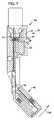
充填工程が完了した後、バイアル瓶132はサービス装置300から除去することができる。その後、カニューレドライバ360が枢動点400の周りで矢印350(図7)の方向に枢動され、図8に示す位置に係止される。カニューレドライバ360は、図8に示す位置に係止され、このときカニューレ駆動構成になる。これにより、カニューレ/針組立品324が注入装置210の補助ポート隔壁228に整列する。このとき、注入装置210の基部222を患者の皮膚に付着させることができる。 After the filling process is complete, the
続いて見られることになるように、このとき第1駆動要素362を解放して、ポート隔壁228を通してカニューレ/針組立品324を駆動し、カニューレ224を展開位置(図9)にすることができる。その後、第2駆動要素366を解放して、カニューレ224はその展開位置にしたまま、針225のみをドライバ360へと元に撤収し、鋭利部分処理のため針を安全にしまい込むことができる。 As will be seen subsequently, the
図8を更に参照すると、第1駆動要素は、ばねを含む。ばね362は、従動部364に連結されている。ばね362は、ドライバ360の両側で整列している1対のアクチュエータボタンを押圧することにより解放することができる。図8に、このような1つのアクチュエータボタン370が示されている。好ましくは、アクチュエータボタンは、ドライバ360がカニューレ駆動構成に係止される際、ばね362及び366を解放するように連結されているだけである。それ故に、このように、ドライバは、カニューレ224を展開させる目的でドライバが適切に位置決めされ係止される際にのみ使用可能となる。 Still referring to FIG. 8, the first drive element includes a spring. The
図9は、カニューレ/針組立品324が、ポート隔壁228及び注入装置210を通って患者の皮膚140の真下まで駆動された後のドライバ360を示す。第1ばね362は解放されており、従動部364はその行程の端にあることに留意されることになる。このとき、第2ばね366を解放して、カニューレ224から針225を撤収することができる。 FIG. 9 shows the
図10は、カニューレ224から針が撤収された後のドライバ360を示す。針225は、注入装置210からポート隔壁228を通してドライバ360内の空洞372へと元に撤収されている。それ故に、第2ばね366は解放されており、従動部368はその行程の端にあることに留意されることになる。カニューレ224から針225が撤収されており、カニューレ224は患者の皮膚140の真下で展開位置にされたままである一方で、針225は、鋭利部分処理のため安全に格納される。 FIG. 10 shows the
カニューレ224が展開した以上は、注入装置210からサービス装置300を除去することができる。このことが図11に示されている。サービス装置210は、注入装置210から除去され分離されている。注入装置210は、患者の皮膚140に付着したまま留まり、カニューレ224を通して患者へ液体薬剤、例えばインスリンを送出する。サービス装置は廃棄することができる。 Once the
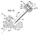
次に図12を参照すると、この図は図2及び図3の装置210の斜視図であり、カニューレ展開前のカニューレと装置との関係を示す。図において指摘することができるように、カニューレ224はカニューレ組立品230の一部であり、カニューレ組立品は、カニューレホルダ又は担体232を更に含む。組立品230はカニューレ針234に載架されており、カニューレ針は、既に説明したように、カニューレが展開した後に、カニューレから撤収される。担体232は、隔壁228により受けられるのを許容する大きさを有する。 Reference is now made to FIG. 12, which is a perspective view of the
図13は、カニューレ組立品230と、隔壁228を含む装置210の部分との断面図である。装置210は、取付部242にて終端している容器導管240を含む。カニューレ担体232は流体カプラ250を含み、流体カプラは、その入力部252とカニューレ224との間に流体連通を提供する。この実施形態において、入力部252は、担体が隔壁228内で受けられてカニューレが展開位置になると取付部242を受けるポートである。 FIG. 13 is a cross-sectional view of
流体カプラは、より詳細には、チャンバ254の形態をとる。チャンバ254は第2入力部256を有し、第2入力部は、貫通可能な膜257の形態をとることができる。第2入力部256を利用して、インスリンのボーラスを提供する注射器の針を受けることができる。また、針234は、カニューレ224が展開した後に、貫通可能な膜257を通して撤収される。チャンバ254がカニューレ224と流体連通していることから、入力部256からチャンバ254を通してカニューレにボーラスを送出することができる。図13において更に指摘することができるように、隔壁は中心軸229を有し、カニューレ224は中心軸225を有する。カニューレ224の中心軸225は、隔壁228の中心軸229からずらされている。このことにより、さもなくば2つの軸225と229とが整列したであろう場合よりもはるかに大きい面積の膜257を利用可能にして注射器の針を受けることが可能になる。 The fluid coupler is more particularly in the form of a
図13において更に指摘することができるように、装置210は、隔壁228内へと延びる掛け金212を含む。掛け金212は、担体232が注入装置210内でその最終的な位置に達し、カニューレ224が展開すると、担体232のフランジ236を係止して係合するように位置決めされている。このように、担体232は、カニューレ224が展開すると、注入装置210に係止される。 As can be further pointed out in FIG. 13, the
次に図14を参照すると、ここでは、カニューレ224の展開中、針234及びカニューレ224が、担体232と共に隔壁228内へ並進するのを見ることができる。カニューレ224は更に、注入装置210の基部222を通って延びているチャネル258により受けられる。 Referring now to FIG. 14, it can now be seen that the
図15は、注入装置210内でその最終的な位置にある担体232を示す。カニューレ224はその展開位置に達し、掛け金212はフランジ236に係合して注入装置210内で担体232を係止している。取付部242もポート252により受けられている。結果として、容器導管240及びチャンバ254は、装置210の容器(図示せず)とカニューレ224との間に流体連通を提供する。カニューレ224はこのとき、装置210の基部222から患者の皮膚140の真下まで延びている。 FIG. 15 shows the
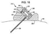
図16は、注入装置210内で係止されているその最終的な位置にある担体232と、針234(図13〜図15)がカニューレ224から撤収された後の、その展開位置にあるカニューレ224とを示す。チャンバ254が、装置210の容器(図示せず)とカニューレ224との間に流体連通を提供するので、注入装置210はこのとき、正確に計られたインスリン投与量を患者の皮膚の真下まで提供できる状態にある。また、第2入力部256も、例えば、注射器からインスリンのボーラスを送出するのに利用可能である。カニューレ224はこのとき、装置210の基部222から患者の皮膚140の真下まで延びている。 FIG. 16 shows the
図17は、隔壁228を含む装置210の、カニューレ組立品430と協動するように修正された部分に沿った、本発明を具体化している別のカニューレ組立品430の断面図である。装置210はこのとき、先の尖った取付部442にて終端している容器導管440を含む。カニューレ担体432は流体カプラ450を含み、流体カプラは、その入力部452とカニューレ424との間に流体連通を提供する。この実施形態において、入力部452は貫通可能な膜453であり、担体430が隔壁228内でその最終的な位置にて受けられると、取付部442が最終的にこの膜から突出する。 FIG. 17 is a cross-sectional view of another
既出の実施形態におけるように、担体432が隔壁228内でその最終的な位置に達すると、カニューレ424はその展開位置になる。装置210の掛け金212が担体432のフランジ436に係合することにより、担体432も注入装置210に係止されることになる。 As in the previous embodiment, when the
また、流体カプラ450はここでも特に、チャンバ454の形態をとる。チャンバ454は、入力部452と流体連通していることに加えて、既出の実施形態におけるように、インスリンのボーラスを受けるように配置されている第2入力部456とも流体連通している。第2入力部456はやはりここでも貫通可能な膜457を含む。 Again, the
図18に見ることができるように、カニューレ424の展開中、針434及びカニューレ424は、担体432と共に隔壁228内へ並進する。カニューレ424は更に、注入装置210の基部222を通って延びているチャネル258により受けられる。 As can be seen in FIG. 18, during deployment of the
図19は、注入装置210内でその最終的な位置にある担体432を示す。カニューレ424はその展開位置に達し、掛け金212はフランジ436に係合して、注入装置210内で担体432を係止している。また、先の尖った取付部442は、膜453(図16及び図17)を貫通し、入力部452により受けられている。結果として、容器導管440及びチャンバ454は、装置210の容器(図示せず)とカニューレ424との間に流体連通を提供する。カニューレ424はこのとき、装置210の基部222から患者の皮膚140の真下まで延びている。 FIG. 19 shows the
図20は、注入装置210内で係止されているその最終的な位置にある担体432と、針434(図17〜図19)がカニューレ424から撤収された後の、その展開位置にあるカニューレ424とを示す。チャンバ454が、装置210の容器(図示せず)とカニューレ424との間に流体連通を提供するので、注入装置210はこのとき、正確に計られたインスリン投与量を患者の皮膚の真下まで提供できる状態にある。また、第2入力部456も、例えば注射器からインスリンのボーラスを送出するのに利用可能である。カニューレ424はこのとき、装置210の基部222から患者の皮膚140の真下まで延びている。 FIG. 20 shows the
図17〜図20においてやはり指摘することができるように、カニューレ担体432はカニューレ補強構造体426を更に含み、カニューレ補強構造体は、カニューレ展開中に曲げに対して増加した抵抗をカニューレ424に提供する。したがって、カニューレ担体432は、針434とカニューレ補強構造体426とカニューレ424とを、患者の皮膚の真下で展開位置にするように配置されている。針434はやはり、カニューレ424及びカニューレ補強426構造体を患者の皮膚の真下で展開位置にしたまま、カニューレ424から撤収されて、カニューレドライバ(図示せず)に戻されるように配置されている。カニューレ補強構造体は、好ましくは、管状部材を含み、この管状部材は、針434とカニューレ424との間で同軸に配置されており、金属、例えばステンレス鋼から形成される。図20に見られるように、補強構造体426は、カニューレの或る部分のみと同一の広がりを有する。 As can also be pointed out in FIGS. 17-20, the
上述のことに加えて、図13〜図20の実施形態の各々において、取付部442及び入力部452は反対にできると理解することができる。換言すれば、取付部442は、担体432、232の一部とすることができ、入力部452は、本発明から逸脱することなく注入装置210内とすることができる。 In addition to the above, it can be appreciated that in each of the embodiments of FIGS. 13-20, the
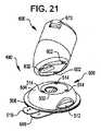
次に図21を参照すると、この図は、本発明の別の実施形態による注入システム490の斜視図である。注入システム490は、注入装置500とカニューレドライバ600とを含む。ここで、装置は、展開すべきカニューレを受けるため、及び、例えば針注射器と共にインスリンのボーラスを受けるための、単一のポートを含む。装置は、本体504と基部506とを含む。基部は、2つの保護用条片508及び510を含む。第1条片508は、除去されると、装置500を受けるように選択される皮膚領域に塗布されるべき消毒薬を暴露する。第2条片510は、除去されると、装置500を患者の皮膚に付着させる際に使用するための接着剤層を剥き出しにする。 Reference is now made to FIG. 21, which is a perspective view of an
先の実施形態におけるように、装置500は、1対のアクチュエータボタンを更に含み、図21では、これらのボタンのうちこのような1つのボタン512を見ることができる。前と同じように、装置500は、好ましくは、アクチュエータボタンの同時押圧によってのみインスリンが患者に分注されるように配置されている。 As in the previous embodiment, the
カニューレドライバ600は、注入装置500を取り外し可能に受けて装置500からのカニューレの展開を促進するように配置されている。そのために、ドライバ600は複数の突起602を含み、これらの突起は、同様の複数の凹部514に整列し、注入装置500の本体504内で摩擦によってこれらの凹部により受けられるように配置されている。突起602及び凹部514は、対応して、カニューレ展開のために、カニューレドライバ600を注入装置500に整列させるという更なる機能を果たすように配置されている。
図22は、カニューレドライバが注入装置上で取り外し可能に受けられ、カニューレを展開できる状態にある、図21の注入装置500及びカニューレドライバ600の断面図である。好ましくは、カニューレドライバは、本明細書で説明されているカニューレ組立品のうちの1つを含む。図22〜図24のカニューレドライバ600は、例えば図13〜図16のカニューレ組立品230を活用している。仮定上、注入装置500の容器520には、液体薬剤、例えばインスリンが既に充填されており、装置500は患者の皮膚140に付着している。 22 is a cross-sectional view of the
図22において指摘することができるように、カニューレドライバ600を注入装置500に取り外し可能に接合するという処理により、ポートがカニューレ担体232に整列している。既出の実施形態におけるように、第1駆動要素662を解放して、ポート隔壁502を通してカニューレ/針組立品230を駆動し、カニューレ224を展開位置(図23)にすることができる。その後、第2駆動要素666を解放して、カニューレ224はその展開位置にしたまま、針234のみをドライバ600へと元に撤収し、鋭利部分処理のため針234を安全にしまい込むことができる。 The port is aligned with the
図22を更に参照すると、第1駆動要素は、ばねを含む。ばね662は、従動部664に連結されている。ばね662は、ドライバ600の両側で整列している1対のアクチュエータボタンを押圧することにより解放することができる。図22に、このような1つのアクチュエータボタン670が示されている。好ましくは、アクチュエータボタンは、注入装置500上でドライバ600が取り外し可能に受けられる際、ばね662及び666を解放するために連結されているだけである。それ故に、このように、ドライバは、カニューレ224を展開させる目的でドライバが適切に位置決めされ係止される際にのみ使用可能となる。 Still referring to FIG. 22, the first drive element includes a spring. The
図23は、カニューレ/針組立品230が、ポート隔壁502及び注入装置500を通って患者の皮膚140の真下まで駆動された後のドライバ600及び注入装置500を示す。第1ばね662は解放されており、従動部664はその行程の端にあることに留意されることになる。このとき、第2ばね666を解放して、カニューレ224から針234を撤収することができる。 FIG. 23 shows
図24は、針234がカニューレ224から撤収された後のドライバ600及び注入装置500を示す。針234は、注入装置500からポート隔壁502を通してドライバ600内の空洞672へと元に撤収されている。それ故に、第2ばね666は解放されており、従動部664はその行程の端にあることに留意されることになる。針234がカニューレ224から撤収されており、カニューレ224は患者の皮膚140の真下で展開位置にされたままである一方で、針234は、鋭利部分処理のため安全に格納される。 FIG. 24 shows the
カニューレ224が展開した以上は、注入装置500からカニューレドライバ600を除去することができる。注入装置500は、患者の皮膚140に付着したまま留まり、液体薬剤、例えばインスリンをカニューレ224を通って患者へと送出することになる。 Once the
本発明の具体的な実施形態が示され説明されたが、修正を行うことができ、従って、添付の特許請求の範囲では、それらの請求項により規定されているような本発明の真の精神および範囲内にあるこのような全ての変更及び修正を網羅することが意図されている。 While specific embodiments of the invention have been shown and described, modifications can be made and, therefore, the true spirit of the invention as defined by the appended claims is set forth in the appended claims. It is intended to cover all such changes and modifications that fall within the scope and scope of the invention.
Claims (45)
Translated fromJapanese前記注入装置に取り外し可能に接合されるように配置され、カニューレを含むカニューレドライバ、ただし、前記カニューレドライバが、前記注入装置から前記患者の皮膚の真下まで延びる展開位置へと前記カニューレを駆動するように配置されているカニューレドライバと、を含む注入システム。A disposable wearable infusion device having a body arranged to adhere to the patient's skin and a container for holding a liquid medicament to be infused into the patient;
A cannula driver arranged to be removably joined to the infusion device and including a cannula, wherein the cannula driver drives the cannula to a deployed position that extends from the infusion device to just below the patient's skin. A cannula driver disposed on the infusion system.
前記カニューレを含むカニューレドライバに前記注入装置を取り外し可能に接合することと、
前記装置を前記患者の皮膚に付着させることと、
前記カニューレドライバから前記装置を通して前記患者の前記皮膚の真下で展開位置に前記カニューレを駆動することと、を含む方法。Providing a disposable infusion device adapted to adhere to a patient's skin and having a container for holding a liquid medicament to be infused into the patient;
Removably joining the infusion device to a cannula driver including the cannula;
Attaching the device to the patient's skin;
Driving the cannula from the cannula driver through the device to a deployed position directly under the patient's skin.
患者の皮膚に接触するように配置されている基部を有する封入体、ただし、前記封入体がポートを有する封入体と、
液体薬物を含むための容器と、
前記容器から前記患者の皮膚の真下まで前記液体薬物を送出するための、前記ポート内で受けられるカニューレ、ただし、前記ポートが、外部源から液体薬物を受けるように配置されており、該ポートによって受けられる液体薬物を外部源から患者の皮膚の真下まで送出するためのカニューレ、と液体連通してなる注入装置。An injection device,
An inclusion body having a base arranged to contact the patient's skin, wherein the inclusion body has a port;
A container for containing a liquid drug;
A cannula received in the port for delivering the liquid drug from the container to directly under the patient's skin, wherein the port is arranged to receive the liquid drug from an external source; An infusion device in fluid communication with a cannula for delivering received liquid medication from an external source to directly under the patient's skin.
患者の皮膚に付着するように配置されている本体と、前記患者に注入されるべき液体薬剤を保持するための容器とを有する、使い捨て装着型の注入装置と、
カニューレを含むカニューレドライバ、ただし、前記カニューレドライバが、前記患者の皮膚の真下で展開位置へと前記カニューレを駆動するように配置されており、前記カニューレが前記注入装置に接合されるように配置されているカニューレドライバと、を含む注入システム。An injection system,
A disposable wearable infusion device having a body arranged to adhere to the patient's skin and a container for holding a liquid medicament to be infused into the patient;
A cannula driver including a cannula, wherein the cannula driver is arranged to drive the cannula to a deployed position directly under the patient's skin, and the cannula is arranged to be joined to the infusion device An infusion system including a cannula driver.
Applications Claiming Priority (5)
| Application Number | Priority Date | Filing Date | Title |
|---|---|---|---|
| US80995706P | 2006-05-31 | 2006-05-31 | |
| US60/809,957 | 2006-05-31 | ||
| US11/641,596 | 2006-12-18 | ||
| US11/641,596US20070282269A1 (en) | 2006-05-31 | 2006-12-18 | Cannula delivery apparatus and method for a disposable infusion device |
| PCT/US2007/012522WO2007142890A2 (en) | 2006-05-31 | 2007-05-25 | Cannula delivery apparatus and method for a disposable infusion device |
Publications (2)
| Publication Number | Publication Date |
|---|---|
| JP2009538693Atrue JP2009538693A (en) | 2009-11-12 |
| JP5126753B2 JP5126753B2 (en) | 2013-01-23 |
Family
ID=38791227
Family Applications (1)
| Application Number | Title | Priority Date | Filing Date |
|---|---|---|---|
| JP2009513211AActiveJP5126753B2 (en) | 2006-05-31 | 2007-05-25 | Cannula delivery instrument and method for a disposable infusion device |
Country Status (7)
| Country | Link |
|---|---|
| US (2) | US20070282269A1 (en) |
| EP (1) | EP2029200A4 (en) |
| JP (1) | JP5126753B2 (en) |
| AU (1) | AU2007255596B2 (en) |
| CA (1) | CA2653601C (en) |
| IL (1) | IL195563A (en) |
| WO (1) | WO2007142890A2 (en) |
Cited By (3)
| Publication number | Priority date | Publication date | Assignee | Title |
|---|---|---|---|---|
| WO2013047855A1 (en)* | 2011-09-26 | 2013-04-04 | テルモ株式会社 | Liquid-drug administration device, puncturing device, liquid-drug filling device, liquid-drug filling method, and liquid-drug filling system |
| JP2015144863A (en)* | 2009-02-10 | 2015-08-13 | シヴィダ・ユーエス・インコーポレイテッドPsivida Us, Inc. | Ocular trocar assembly |
| WO2020158814A1 (en)* | 2019-01-30 | 2020-08-06 | 株式会社旭ポリスライダー | Cannula inserter |
Families Citing this family (179)
| Publication number | Priority date | Publication date | Assignee | Title |
|---|---|---|---|---|
| US7999435B2 (en) | 2004-06-14 | 2011-08-16 | Massachusetts Institute Of Technology | Electrochemical actuator |
| US8247946B2 (en) | 2004-06-14 | 2012-08-21 | Massachusetts Institute Of Technology | Electrochemical actuator |
| US7994686B2 (en) | 2004-06-14 | 2011-08-09 | Massachusetts Institute Of Technology | Electrochemical methods, devices, and structures |
| US7872396B2 (en) | 2004-06-14 | 2011-01-18 | Massachusetts Institute Of Technology | Electrochemical actuator |
| WO2005124918A2 (en) | 2004-06-14 | 2005-12-29 | Massachusetts Institute Of Technology | Electrochemical actuating methods, devices and structures |
| EP1762259B2 (en)* | 2005-09-12 | 2025-01-01 | Unomedical A/S | Inserter for an infusion set with a first and second spring units |
| WO2007098771A2 (en) | 2006-02-28 | 2007-09-07 | Unomedical A/S | Inserter for infusion part and infusion part provided with needle protector |
| CA2653764A1 (en) | 2006-06-09 | 2007-12-13 | Unomedical A/S | Mounting pad |
| JP2009545341A (en) | 2006-08-02 | 2009-12-24 | ウノメディカル アクティーゼルスカブ | Cannula and delivery device |
| US7931621B2 (en)* | 2007-05-11 | 2011-04-26 | Calibra Medical, Inc. | Infusion assembly |
| CN101801438B (en)* | 2007-07-20 | 2013-08-07 | 梅丁格有限公司 | Manually operable portable infusion device |
| EP2178584A2 (en)* | 2007-07-26 | 2010-04-28 | Entra Pharmaceuticals Inc. | Skin-patch pump comprising a changing-volume electrochemical actuator |
| US9345836B2 (en) | 2007-10-02 | 2016-05-24 | Medimop Medical Projects Ltd. | Disengagement resistant telescoping assembly and unidirectional method of assembly for such |
| US7967795B1 (en) | 2010-01-19 | 2011-06-28 | Lamodel Ltd. | Cartridge interface assembly with driving plunger |
| US10420880B2 (en) | 2007-10-02 | 2019-09-24 | West Pharma. Services IL, Ltd. | Key for securing components of a drug delivery system during assembly and/or transport and methods of using same |
| BRPI0817907B8 (en) | 2007-10-02 | 2021-06-22 | Lamodel Ltd | apparatus for administering a substance to an individual |
| US9656019B2 (en) | 2007-10-02 | 2017-05-23 | Medimop Medical Projects Ltd. | Apparatuses for securing components of a drug delivery system during transport and methods of using same |
| DE102007049446A1 (en) | 2007-10-16 | 2009-04-23 | Cequr Aps | Catheter introducer |
| US7976505B2 (en)* | 2007-12-19 | 2011-07-12 | Calibra Medical, Inc. | Disposable infusion device negative pressure filling apparatus and method |
| US7815609B2 (en)* | 2007-12-19 | 2010-10-19 | Calibra Medical, Inc. | Disposable infusion device positive pressure filling apparatus and method |
| KR20100132495A (en) | 2008-02-08 | 2010-12-17 | 우노메디컬 에이/에스 | Injector assembly |
| ATE522240T1 (en)* | 2008-02-13 | 2011-09-15 | Unomedical As | SEAL BETWEEN A CANNULAR PART AND A FLUID PATH |
| US8231577B2 (en)* | 2008-06-26 | 2012-07-31 | Calibra Medical, Inc. | Disposable infusion device with automatically releasable cannula driver |
| EP2349400B1 (en)* | 2008-06-26 | 2021-01-06 | Calibra Medical LLC | Disposable infusion device with cannula port cover |
| US8128597B2 (en) | 2008-06-26 | 2012-03-06 | Calibra Medical, Inc. | Disposable infusion device with cannula port cover |
| US7959598B2 (en) | 2008-08-20 | 2011-06-14 | Asante Solutions, Inc. | Infusion pump systems and methods |
| US12097357B2 (en) | 2008-09-15 | 2024-09-24 | West Pharma. Services IL, Ltd. | Stabilized pen injector |
| US9393369B2 (en) | 2008-09-15 | 2016-07-19 | Medimop Medical Projects Ltd. | Stabilized pen injector |
| AU2009331635A1 (en) | 2008-12-22 | 2011-06-23 | Unomedical A/S | Medical device comprising adhesive pad |
| KR20120047896A (en) | 2009-08-07 | 2012-05-14 | 우노메디컬 에이/에스 | Delivery device with sensor and one or more cannulas |
| US8547239B2 (en) | 2009-08-18 | 2013-10-01 | Cequr Sa | Methods for detecting failure states in a medicine delivery device |
| US8672873B2 (en) | 2009-08-18 | 2014-03-18 | Cequr Sa | Medicine delivery device having detachable pressure sensing unit |
| US8157769B2 (en) | 2009-09-15 | 2012-04-17 | Medimop Medical Projects Ltd. | Cartridge insertion assembly for drug delivery system |
| US10071198B2 (en) | 2012-11-02 | 2018-09-11 | West Pharma. Servicees IL, Ltd. | Adhesive structure for medical device |
| US10071196B2 (en) | 2012-05-15 | 2018-09-11 | West Pharma. Services IL, Ltd. | Method for selectively powering a battery-operated drug-delivery device and device therefor |
| US8348898B2 (en) | 2010-01-19 | 2013-01-08 | Medimop Medical Projects Ltd. | Automatic needle for drug pump |
| KR20130018783A (en) | 2010-03-30 | 2013-02-25 | 우노메디컬 에이/에스 | Medical device |
| USD652503S1 (en) | 2010-04-08 | 2012-01-17 | Cequr Sa | Medical device |
| USD652502S1 (en) | 2010-04-08 | 2012-01-17 | Cequr Sa | Medical device |
| WO2011140359A2 (en) | 2010-05-05 | 2011-11-10 | Springleaf Therapeutics, Inc. | Systems and methods for delivering a therapeutic agent |
| EP2569031B1 (en) | 2010-05-10 | 2017-10-11 | Medimop Medical Projects Ltd. | Low volume accurate injector |
| US9216249B2 (en) | 2010-09-24 | 2015-12-22 | Perqflo, Llc | Infusion pumps |
| US8915879B2 (en) | 2010-09-24 | 2014-12-23 | Perqflo, Llc | Infusion pumps |
| US9498573B2 (en) | 2010-09-24 | 2016-11-22 | Perqflo, Llc | Infusion pumps |
| US9381300B2 (en) | 2010-09-24 | 2016-07-05 | Perqflo, Llc | Infusion pumps |
| EP2433663A1 (en) | 2010-09-27 | 2012-03-28 | Unomedical A/S | Insertion system |
| EP2436412A1 (en) | 2010-10-04 | 2012-04-04 | Unomedical A/S | A sprinkler cannula |
| US8905972B2 (en) | 2010-11-20 | 2014-12-09 | Perqflo, Llc | Infusion pumps |
| WO2012083174A2 (en) | 2010-12-17 | 2012-06-21 | Massachusetts Institute Of Technology | Electrochemical actuators |
| USD702834S1 (en) | 2011-03-22 | 2014-04-15 | Medimop Medical Projects Ltd. | Cartridge for use in injection device |
| CA2845379C (en) | 2011-09-02 | 2019-08-06 | Unitract Syringe Pty Ltd | Insertion mechanism for a drug delivery pump |
| WO2013050277A1 (en) | 2011-10-05 | 2013-04-11 | Unomedical A/S | Inserter for simultaneous insertion of multiple transcutaneous parts |
| DK3045187T3 (en) | 2011-10-14 | 2019-06-11 | Amgen Inc | INJECTOR AND COLLECTION PROCEDURE |
| EP2583715A1 (en) | 2011-10-19 | 2013-04-24 | Unomedical A/S | Infusion tube system and method for manufacture |
| US9440051B2 (en) | 2011-10-27 | 2016-09-13 | Unomedical A/S | Inserter for a multiplicity of subcutaneous parts |
| EP2809375B1 (en) | 2012-01-31 | 2021-08-11 | Medimop Medical Projects Ltd. | Time dependent drug delivery apparatus |
| WO2013140790A1 (en)* | 2012-03-22 | 2013-09-26 | テルモ株式会社 | Puncture device and drug solution administration device |
| US10668213B2 (en) | 2012-03-26 | 2020-06-02 | West Pharma. Services IL, Ltd. | Motion activated mechanisms for a drug delivery device |
| US9463280B2 (en) | 2012-03-26 | 2016-10-11 | Medimop Medical Projects Ltd. | Motion activated septum puncturing drug delivery device |
| US9072827B2 (en) | 2012-03-26 | 2015-07-07 | Medimop Medical Projects Ltd. | Fail safe point protector for needle safety flap |
| EP4406568A3 (en) | 2012-03-30 | 2024-10-16 | Insulet Corporation | Fluid delivery device with transcutaneous access tool, insertion mechanism and blood glucose monitoring for use therewith |
| BR112015000541A2 (en)* | 2012-07-11 | 2017-08-08 | Unitract Syringe Pty Ltd | insertion mechanism, drug delivery pump and method of operating an insertion mechanism |
| WO2014046950A1 (en) | 2012-09-24 | 2014-03-27 | Enable Injections, Llc | Medication vial and injector assemblies and methods of use |
| US9782538B2 (en) | 2012-09-27 | 2017-10-10 | Becton, Dickinson And Company | Angled inserter for drug infusion |
| US9421323B2 (en) | 2013-01-03 | 2016-08-23 | Medimop Medical Projects Ltd. | Door and doorstop for portable one use drug delivery apparatus |
| US10080839B2 (en) | 2013-03-14 | 2018-09-25 | Becton, Dickinson And Company | Angled inserter for drug infusion |
| US9821113B2 (en) | 2013-03-15 | 2017-11-21 | Becton, Dickinson And Company | Automatic angled infusion set assembly |
| US9373269B2 (en) | 2013-03-18 | 2016-06-21 | Lifescan Scotland Limited | Patch pump training device |
| SG11201507878SA (en) | 2013-03-22 | 2015-10-29 | Amgen Inc | Injector and method of assembly |
| US9011164B2 (en) | 2013-04-30 | 2015-04-21 | Medimop Medical Projects Ltd. | Clip contact for easy installation of printed circuit board PCB |
| US9889256B2 (en) | 2013-05-03 | 2018-02-13 | Medimop Medical Projects Ltd. | Sensing a status of an infuser based on sensing motor control and power input |
| ES2728054T3 (en) | 2013-06-18 | 2019-10-22 | Enable Injections Inc | Vial transfer and injection device |
| US9561324B2 (en) | 2013-07-19 | 2017-02-07 | Bigfoot Biomedical, Inc. | Infusion pump system and method |
| BR112016008946B1 (en) | 2013-10-24 | 2022-12-27 | Amgen Inc | INJECTORS AND METHOD FOR ASSEMBLING THE INJECTORS |
| GB2523989B (en) | 2014-01-30 | 2020-07-29 | Insulet Netherlands B V | Therapeutic product delivery system and method of pairing |
| US10195342B2 (en) | 2014-04-24 | 2019-02-05 | Becton, Dickinson And Company | Cannula deployment mechanism |
| CN106470717B (en) | 2014-06-03 | 2020-09-11 | 安姆根有限公司 | Drug delivery system and method of use |
| CA2960278A1 (en) | 2014-09-11 | 2016-03-17 | Psivida Us, Inc. | Injector apparatus |
| CN107073205A (en)* | 2014-09-15 | 2017-08-18 | 赛诺菲 | Medicament delivery device with disinfection pad |
| EP3200851A1 (en) | 2014-09-29 | 2017-08-09 | Unitract Syringe Pty Ltd | Rigid needle insertion mechanism for a drug delivery pump |
| US12178992B2 (en) | 2014-09-30 | 2024-12-31 | Medtronic Minimed, Inc. | Different disposable assemblies for the same reusable assembly |
| US10159786B2 (en) | 2014-09-30 | 2018-12-25 | Perqflo, Llc | Hybrid ambulatory infusion pumps |
| ES2549462B1 (en)* | 2014-10-24 | 2016-02-10 | Kiro Robotics, S.L. | Method for automatic filling of containers for intravenous administration medication in a machine for automatic preparation of intravenous medication |
| JP6716566B2 (en) | 2014-12-19 | 2020-07-01 | アムジエン・インコーポレーテツド | Drug delivery device with proximity sensor |
| US11357916B2 (en) | 2014-12-19 | 2022-06-14 | Amgen Inc. | Drug delivery device with live button or user interface field |
| US10737016B2 (en) | 2015-02-18 | 2020-08-11 | Medtronic Minimed, Inc. | Ambulatory infusion pumps and reservoir assemblies for use with same |
| JP2018505756A (en) | 2015-02-18 | 2018-03-01 | インシュレット コーポレイション | Fluid delivery and infusion device and method of use thereof |
| US10251813B2 (en) | 2015-03-04 | 2019-04-09 | West Pharma. Services IL, Ltd. | Flexibly mounted cartridge alignment collar for drug delivery device |
| US9795534B2 (en) | 2015-03-04 | 2017-10-24 | Medimop Medical Projects Ltd. | Compliant coupling assembly for cartridge coupling of a drug delivery device |
| US9744297B2 (en) | 2015-04-10 | 2017-08-29 | Medimop Medical Projects Ltd. | Needle cannula position as an input to operational control of an injection device |
| US10293120B2 (en) | 2015-04-10 | 2019-05-21 | West Pharma. Services IL, Ltd. | Redundant injection device status indication |
| US10149943B2 (en) | 2015-05-29 | 2018-12-11 | West Pharma. Services IL, Ltd. | Linear rotation stabilizer for a telescoping syringe stopper driverdriving assembly |
| CN113181477B (en) | 2015-06-04 | 2023-07-14 | 麦迪麦珀医疗工程有限公司 | Cartridge insertion for drug delivery device |
| US10576207B2 (en) | 2015-10-09 | 2020-03-03 | West Pharma. Services IL, Ltd. | Angled syringe patch injector |
| US9987432B2 (en) | 2015-09-22 | 2018-06-05 | West Pharma. Services IL, Ltd. | Rotation resistant friction adapter for plunger driver of drug delivery device |
| US11065381B2 (en) | 2015-10-05 | 2021-07-20 | E3D A.C.A.L. | Infusion pump device and method for use thereof |
| US11318254B2 (en) | 2015-10-09 | 2022-05-03 | West Pharma. Services IL, Ltd. | Injector needle cap remover |
| USD851755S1 (en) | 2015-10-22 | 2019-06-18 | Eyepoint Pharmaceuticals Us, Inc. | Ocular inserter |
| US10413665B2 (en) | 2015-11-25 | 2019-09-17 | Insulet Corporation | Wearable medication delivery device |
| EP3374905A1 (en) | 2016-01-13 | 2018-09-19 | Bigfoot Biomedical, Inc. | User interface for diabetes management system |
| US10806859B2 (en) | 2016-01-14 | 2020-10-20 | Bigfoot Biomedical, Inc. | Adjusting insulin delivery rates |
| HK1256995A1 (en) | 2016-01-14 | 2019-10-11 | Bigfoot Biomedical, Inc. | Occlusion resolution in medication delivery devices, systems, and methods |
| USD829894S1 (en) | 2016-01-21 | 2018-10-02 | Becton, Dickinson And Company | Wearable drug delivery device baseplate |
| USD830547S1 (en) | 2016-01-21 | 2018-10-09 | Becton, Dickinson And Company | Adhesive liner for wearable drug delivery device |
| US10646643B2 (en) | 2016-01-21 | 2020-05-12 | West Pharma. Services IL, Ltd. | Needle insertion and retraction mechanism |
| USD829889S1 (en) | 2016-01-21 | 2018-10-02 | Becton, Dickinson And Company | Wearable drug delivery device with adhesive |
| USD830537S1 (en) | 2016-01-21 | 2018-10-09 | Becton, Dickinson And Company | Wearable drug delivery device with adhesive and liner |
| JP6885960B2 (en) | 2016-01-21 | 2021-06-16 | ウェスト ファーマ サービシーズ イスラエル リミテッド | Drug delivery device with visual indicators |
| USD805631S1 (en) | 2016-01-21 | 2017-12-19 | Becton, Dickinson And Company | Drug delivery device with insertion mechanism button safety |
| EP3711793B1 (en) | 2016-01-21 | 2021-12-01 | West Pharma Services IL, Ltd. | A method of connecting a cartridge to an automatic injector |
| USD857191S1 (en) | 2016-01-21 | 2019-08-20 | Becton, Dickinson And Company | Wearable drug delivery device |
| USD806232S1 (en) | 2016-01-21 | 2017-12-26 | Becton, Dickinson And Company | Drug delivery device with insertion mechanism |
| US10363342B2 (en) | 2016-02-04 | 2019-07-30 | Insulet Corporation | Anti-inflammatory cannula |
| EP3413954B1 (en) | 2016-02-12 | 2025-09-03 | Medtronic MiniMed, Inc. | Ambulatory infusion pump and assemblies for use with same |
| US11389597B2 (en) | 2016-03-16 | 2022-07-19 | West Pharma. Services IL, Ltd. | Staged telescopic screw assembly having different visual indicators |
| US12383166B2 (en) | 2016-05-23 | 2025-08-12 | Insulet Corporation | Insulin delivery system and methods with risk-based set points |
| US10363374B2 (en) | 2016-05-26 | 2019-07-30 | Insulet Corporation | Multi-dose drug delivery device |
| CN109310831B (en) | 2016-06-02 | 2021-11-23 | 西医药服务以色列有限公司 | Three position needle retraction |
| US11338090B2 (en) | 2016-08-01 | 2022-05-24 | West Pharma. Services IL, Ltd. | Anti-rotation cartridge pin |
| JP7059251B2 (en) | 2016-08-01 | 2022-04-25 | ウェスト ファーマ サービシーズ イスラエル リミテッド | A spring that prevents the door from closing halfway |
| EP3730169B1 (en) | 2016-08-14 | 2023-08-02 | Insulet Corporation | Drug delivery device with detection of position of the plunger |
| US10765807B2 (en) | 2016-09-23 | 2020-09-08 | Insulet Corporation | Fluid delivery device with sensor |
| WO2018067645A1 (en) | 2016-10-07 | 2018-04-12 | Insulet Corporation | Multi-stage delivery system |
| US10780217B2 (en) | 2016-11-10 | 2020-09-22 | Insulet Corporation | Ratchet drive for on body delivery system |
| EP3500161A4 (en) | 2016-12-12 | 2020-01-08 | Bigfoot Biomedical, Inc. | ALARMS AND WARNINGS FOR MEDICINE DELIVERY DEVICES AND RELATED SYSTEMS AND METHODS |
| US10758675B2 (en) | 2017-01-13 | 2020-09-01 | Bigfoot Biomedical, Inc. | System and method for adjusting insulin delivery |
| EP3568859A1 (en) | 2017-01-13 | 2019-11-20 | Bigfoot Biomedical, Inc. | Insulin delivery methods, systems and devices |
| US10881792B2 (en) | 2017-01-13 | 2021-01-05 | Bigfoot Biomedical, Inc. | System and method for adjusting insulin delivery |
| US10500334B2 (en) | 2017-01-13 | 2019-12-10 | Bigfoot Biomedical, Inc. | System and method for adjusting insulin delivery |
| WO2018136699A1 (en) | 2017-01-19 | 2018-07-26 | Insulet Corporation | Cartridge hold-up volume reduction |
| WO2018156548A1 (en) | 2017-02-22 | 2018-08-30 | Insulet Corporation | Needle insertion mechanisms for drug containers |
| US10695485B2 (en) | 2017-03-07 | 2020-06-30 | Insulet Corporation | Very high volume user filled drug delivery device |
| US10413658B2 (en) | 2017-03-31 | 2019-09-17 | Capillary Biomedical, Inc. | Helical insertion infusion device |
| EP3630226A1 (en) | 2017-05-30 | 2020-04-08 | West Pharma. Services Il, Ltd. | Modular drive train for wearable injector |
| US11280327B2 (en) | 2017-08-03 | 2022-03-22 | Insulet Corporation | Micro piston pump |
| US10973978B2 (en) | 2017-08-03 | 2021-04-13 | Insulet Corporation | Fluid flow regulation arrangements for drug delivery devices |
| US10814062B2 (en) | 2017-08-31 | 2020-10-27 | Becton, Dickinson And Company | Reservoir with low volume sensor |
| US11786668B2 (en) | 2017-09-25 | 2023-10-17 | Insulet Corporation | Drug delivery devices, systems, and methods with force transfer elements |
| EP3687600B1 (en) | 2017-09-26 | 2022-04-27 | Insulet Corporation | Needle mechanism module for drug delivery device |
| US11147931B2 (en) | 2017-11-17 | 2021-10-19 | Insulet Corporation | Drug delivery device with air and backflow elimination |
| JP7402799B2 (en) | 2017-12-22 | 2023-12-21 | ウェスト ファーマ サービシーズ イスラエル リミテッド | Syringes available with different cartridge sizes |
| US11109890B2 (en) | 2018-01-25 | 2021-09-07 | Kyphon Sarl | Vertebral body access cannula with enhanced bending stiffness |
| USD928199S1 (en) | 2018-04-02 | 2021-08-17 | Bigfoot Biomedical, Inc. | Medication delivery device with icons |
| EP4492399A3 (en) | 2018-05-04 | 2025-03-26 | Insulet Corporation | Safety constraints for a control algorithm-based drug delivery system |
| US10874803B2 (en) | 2018-05-31 | 2020-12-29 | Insulet Corporation | Drug cartridge with drive system |
| US11229736B2 (en) | 2018-06-06 | 2022-01-25 | Insulet Corporation | Linear shuttle pump for drug delivery |
| CN108553710B (en)* | 2018-06-27 | 2023-07-28 | 烟台凯博机械自动化设备有限公司 | Automatic needle inserting and pulling and bottle changing device |
| WO2020069406A1 (en) | 2018-09-28 | 2020-04-02 | Insulet Corporation | Activity mode for artificial pancreas system |
| US11565039B2 (en) | 2018-10-11 | 2023-01-31 | Insulet Corporation | Event detection for drug delivery system |
| EP3877018A4 (en) | 2018-11-08 | 2022-08-10 | Capillary Biomedical, Inc. | LINEAR INTRODUCER WITH ROTARY DRIVE |
| US11446435B2 (en) | 2018-11-28 | 2022-09-20 | Insulet Corporation | Drug delivery shuttle pump system and valve assembly |
| USD920343S1 (en) | 2019-01-09 | 2021-05-25 | Bigfoot Biomedical, Inc. | Display screen or portion thereof with graphical user interface associated with insulin delivery |
| US11801344B2 (en) | 2019-09-13 | 2023-10-31 | Insulet Corporation | Blood glucose rate of change modulation of meal and correction insulin bolus quantity |
| US11935637B2 (en) | 2019-09-27 | 2024-03-19 | Insulet Corporation | Onboarding and total daily insulin adaptivity |
| US11369735B2 (en) | 2019-11-05 | 2022-06-28 | Insulet Corporation | Component positioning of a linear shuttle pump |
| EP4354455A3 (en) | 2019-12-06 | 2024-07-10 | Insulet Corporation | Techniques and devices providing adaptivity and personalization in diabetes treatment |
| US11833329B2 (en) | 2019-12-20 | 2023-12-05 | Insulet Corporation | Techniques for improved automatic drug delivery performance using delivery tendencies from past delivery history and use patterns |
| AU2021206190A1 (en) | 2020-01-06 | 2022-08-18 | Insulet Corporation | Prediction of meal and/or exercise events based on persistent residuals |
| WO2021158580A1 (en) | 2020-02-03 | 2021-08-12 | Insulet Corporation | Use of fuzzy logic in predicting user behavior affecting blood glucose concentration |
| US11551802B2 (en) | 2020-02-11 | 2023-01-10 | Insulet Corporation | Early meal detection and calorie intake detection |
| US11547800B2 (en) | 2020-02-12 | 2023-01-10 | Insulet Corporation | User parameter dependent cost function for personalized reduction of hypoglycemia and/or hyperglycemia in a closed loop artificial pancreas system |
| US11986630B2 (en) | 2020-02-12 | 2024-05-21 | Insulet Corporation | Dual hormone delivery system for reducing impending hypoglycemia and/or hyperglycemia risk |
| US11324889B2 (en) | 2020-02-14 | 2022-05-10 | Insulet Corporation | Compensation for missing readings from a glucose monitor in an automated insulin delivery system |
| US11607493B2 (en) | 2020-04-06 | 2023-03-21 | Insulet Corporation | Initial total daily insulin setting for user onboarding |
| EP3928814A1 (en)* | 2020-06-23 | 2021-12-29 | TecMed AG | Wearable drug delivery device |
| WO2022020197A1 (en) | 2020-07-22 | 2022-01-27 | Insulet Corporation | Open-loop insulin delivery basal parameters based on insulin delivery records |
| US11684716B2 (en) | 2020-07-31 | 2023-06-27 | Insulet Corporation | Techniques to reduce risk of occlusions in drug delivery systems |
| EP4204066A4 (en) | 2020-08-28 | 2024-11-13 | Tandem Diabetes Care, Inc. | INSULIN INFUSION SET |
| EP4221785A1 (en) | 2020-09-30 | 2023-08-09 | Insulet Corporation | Drug delivery device with integrated optical-based glucose monitor |
| WO2022072618A1 (en) | 2020-09-30 | 2022-04-07 | Insulet Corporation | Secure wireless communications between a glucose monitor and other devices |
| AU2022205300B2 (en) | 2021-01-08 | 2025-04-17 | Insulet Corporation | Single actuated precision dose intermediate pumping chamber |
| US11160925B1 (en) | 2021-01-29 | 2021-11-02 | Insulet Corporation | Automatic drug delivery system for delivery of a GLP-1 therapeutic |
| US11904140B2 (en) | 2021-03-10 | 2024-02-20 | Insulet Corporation | Adaptable asymmetric medicament cost component in a control system for medicament delivery |
| EP4305636A1 (en) | 2021-03-10 | 2024-01-17 | Insulet Corporation | A medicament delivery device with an adjustable and piecewise analyte level cost component to address persistent positive analyte level excursions |
| EP4346945A1 (en) | 2021-05-28 | 2024-04-10 | Insulet Corporation | Spring-based status sensors |
| EP4101482A1 (en) | 2021-06-07 | 2022-12-14 | Insulet Corporation | Exercise safety prediction based on physiological conditions |
| US11738144B2 (en) | 2021-09-27 | 2023-08-29 | Insulet Corporation | Techniques enabling adaptation of parameters in aid systems by user input |
| US11439754B1 (en) | 2021-12-01 | 2022-09-13 | Insulet Corporation | Optimizing embedded formulations for drug delivery |
| US12097355B2 (en) | 2023-01-06 | 2024-09-24 | Insulet Corporation | Automatically or manually initiated meal bolus delivery with subsequent automatic safety constraint relaxation |
Citations (3)
| Publication number | Priority date | Publication date | Assignee | Title |
|---|---|---|---|---|
| US5257980A (en)* | 1993-04-05 | 1993-11-02 | Minimed Technologies, Ltd. | Subcutaneous injection set with crimp-free soft cannula |
| JP2000515394A (en)* | 1995-12-11 | 2000-11-21 | エラン コーポレーション ピーエルシー | Cartridge based drug delivery device |
| JP2004524926A (en)* | 2001-04-06 | 2004-08-19 | ディセトロニック・ライセンシング・アクチェンゲゼルシャフト | Injection device |
Family Cites Families (18)
| Publication number | Priority date | Publication date | Assignee | Title |
|---|---|---|---|---|
| US5851197A (en)* | 1997-02-05 | 1998-12-22 | Minimed Inc. | Injector for a subcutaneous infusion set |
| US6186982B1 (en)* | 1998-05-05 | 2001-02-13 | Elan Corporation, Plc | Subcutaneous drug delivery device with improved filling system |
| US6830562B2 (en)* | 2001-09-27 | 2004-12-14 | Unomedical A/S | Injector device for placing a subcutaneous infusion set |
| US8372016B2 (en)* | 2002-04-19 | 2013-02-12 | Sanofi-Aventis Deutschland Gmbh | Method and apparatus for body fluid sampling and analyte sensing |
| US6960192B1 (en)* | 2002-04-23 | 2005-11-01 | Insulet Corporation | Transcutaneous fluid delivery system |
| US6923791B2 (en)* | 2003-03-31 | 2005-08-02 | Sterling Medivations, Inc. | Infusion device having offset flow path |
| JP4509100B2 (en) | 2003-05-08 | 2010-07-21 | ノボ・ノルデイスク・エー/エス | Infusion device attachable to skin with removable needle insertion actuation |
| ATE392223T1 (en) | 2003-05-08 | 2008-05-15 | Novo Nordisk As | INTERNAL NEEDLE INTRODUCER |
| KR20060099520A (en)* | 2003-10-21 | 2006-09-19 | 노보 노르디스크 에이/에스 | Medical Skin Mounting Device |
| US8062250B2 (en)* | 2004-08-10 | 2011-11-22 | Unomedical A/S | Cannula device |
| EP1804859A1 (en) | 2004-09-22 | 2007-07-11 | Novo Nordisk A/S | Medical device with cannula inserter |
| WO2006032689A1 (en)* | 2004-09-22 | 2006-03-30 | Novo Nordisk A/S | Medical device with transcutaneous cannula device |
| US7699833B2 (en)* | 2005-05-06 | 2010-04-20 | Moberg Sheldon B | Pump assembly and method for infusion device |
| US20070093753A1 (en)* | 2005-09-19 | 2007-04-26 | Lifescan, Inc. | Malfunction Detection Via Pressure Pulsation |
| US7794434B2 (en)* | 2006-08-23 | 2010-09-14 | Medtronic Minimed, Inc. | Systems and methods allowing for reservoir filling and infusion medium delivery |
| US7811262B2 (en)* | 2006-08-23 | 2010-10-12 | Medtronic Minimed, Inc. | Systems and methods allowing for reservoir filling and infusion medium delivery |
| US7682338B2 (en)* | 2006-08-23 | 2010-03-23 | Medtronic Minimed, Inc. | Infusion medium delivery system, device and method with needle inserter and needle inserter device and method |
| JP5102350B2 (en)* | 2007-04-30 | 2012-12-19 | メドトロニック ミニメド インコーポレイテッド | Reservoir filling / bubble management / infusion medium delivery system and method using the system |
- 2006
- 2006-12-18USUS11/641,596patent/US20070282269A1/ennot_activeAbandoned
- 2007
- 2007-05-25AUAU2007255596Apatent/AU2007255596B2/enactiveActive
- 2007-05-25WOPCT/US2007/012522patent/WO2007142890A2/enactiveApplication Filing
- 2007-05-25EPEP07809198.0Apatent/EP2029200A4/ennot_activeWithdrawn
- 2007-05-25JPJP2009513211Apatent/JP5126753B2/enactiveActive
- 2007-05-25CACA2653601Apatent/CA2653601C/enactiveActive
- 2008
- 2008-11-27ILIL195563Apatent/IL195563A/ennot_activeIP Right Cessation
- 2009
- 2009-04-06USUS12/418,929patent/US20090192471A1/ennot_activeAbandoned
Patent Citations (3)
| Publication number | Priority date | Publication date | Assignee | Title |
|---|---|---|---|---|
| US5257980A (en)* | 1993-04-05 | 1993-11-02 | Minimed Technologies, Ltd. | Subcutaneous injection set with crimp-free soft cannula |
| JP2000515394A (en)* | 1995-12-11 | 2000-11-21 | エラン コーポレーション ピーエルシー | Cartridge based drug delivery device |
| JP2004524926A (en)* | 2001-04-06 | 2004-08-19 | ディセトロニック・ライセンシング・アクチェンゲゼルシャフト | Injection device |
Cited By (6)
| Publication number | Priority date | Publication date | Assignee | Title |
|---|---|---|---|---|
| JP2015144863A (en)* | 2009-02-10 | 2015-08-13 | シヴィダ・ユーエス・インコーポレイテッドPsivida Us, Inc. | Ocular trocar assembly |
| WO2013047855A1 (en)* | 2011-09-26 | 2013-04-04 | テルモ株式会社 | Liquid-drug administration device, puncturing device, liquid-drug filling device, liquid-drug filling method, and liquid-drug filling system |
| US9220838B2 (en) | 2011-09-26 | 2015-12-29 | Terumo Kabushiki Kaisha | Puncture device |
| WO2020158814A1 (en)* | 2019-01-30 | 2020-08-06 | 株式会社旭ポリスライダー | Cannula inserter |
| JPWO2020158814A1 (en)* | 2019-01-30 | 2021-12-02 | 株式会社旭ポリスライダー | Cannula Inserter |
| JP7339287B2 (en) | 2019-01-30 | 2023-09-05 | 株式会社旭ポリスライダー | cannula inserter |
Also Published As
| Publication number | Publication date |
|---|---|
| AU2007255596A1 (en) | 2007-12-13 |
| WO2007142890A2 (en) | 2007-12-13 |
| EP2029200A2 (en) | 2009-03-04 |
| US20090192471A1 (en) | 2009-07-30 |
| US20070282269A1 (en) | 2007-12-06 |
| CA2653601A1 (en) | 2007-12-13 |
| IL195563A (en) | 2013-01-31 |
| CA2653601C (en) | 2015-07-07 |
| WO2007142890A9 (en) | 2008-02-14 |
| AU2007255596B2 (en) | 2014-04-03 |
| JP5126753B2 (en) | 2013-01-23 |
| WO2007142890A3 (en) | 2008-09-18 |
| IL195563A0 (en) | 2009-09-01 |
| EP2029200A4 (en) | 2014-09-17 |
Similar Documents
| Publication | Publication Date | Title |
|---|---|---|
| JP5126753B2 (en) | Cannula delivery instrument and method for a disposable infusion device | |
| US7938801B2 (en) | Disposable infusion device filling apparatus and method | |
| US11839738B2 (en) | Medication infusion device | |
| US7976505B2 (en) | Disposable infusion device negative pressure filling apparatus and method | |
| US12208236B2 (en) | Injection or infusion device comprising an improved housing and release liner for removing sterile barrier films using the release liner | |
| CN100574819C (en) | Pivotable injection needle unit | |
| CN1874809B (en) | Skin mountable medical device | |
| EP2830499B1 (en) | Fluid delivery device with transcutaneous access tool, insertion mechansim and blood glucose monitoring for use therewith | |
| US7815609B2 (en) | Disposable infusion device positive pressure filling apparatus and method | |
| JP4509100B2 (en) | Infusion device attachable to skin with removable needle insertion actuation | |
| US7931621B2 (en) | Infusion assembly | |
| EP3829678B1 (en) | Needle insertion and retraction mechanism | |
| JP2011516097A (en) | Liquid pump transport apparatus and method | |
| WO2022086697A1 (en) | Drug delivery system |
Legal Events
| Date | Code | Title | Description |
|---|---|---|---|
| RD02 | Notification of acceptance of power of attorney | Free format text:JAPANESE INTERMEDIATE CODE: A7422 Effective date:20100423 | |
| RD04 | Notification of resignation of power of attorney | Free format text:JAPANESE INTERMEDIATE CODE: A7424 Effective date:20100426 | |
| A621 | Written request for application examination | Free format text:JAPANESE INTERMEDIATE CODE: A621 Effective date:20100521 | |
| A977 | Report on retrieval | Free format text:JAPANESE INTERMEDIATE CODE: A971007 Effective date:20111220 | |
| A131 | Notification of reasons for refusal | Free format text:JAPANESE INTERMEDIATE CODE: A131 Effective date:20120110 | |
| A521 | Request for written amendment filed | Free format text:JAPANESE INTERMEDIATE CODE: A523 Effective date:20120323 | |
| TRDD | Decision of grant or rejection written | ||
| A01 | Written decision to grant a patent or to grant a registration (utility model) | Free format text:JAPANESE INTERMEDIATE CODE: A01 Effective date:20121002 | |
| A01 | Written decision to grant a patent or to grant a registration (utility model) | Free format text:JAPANESE INTERMEDIATE CODE: A01 | |
| A61 | First payment of annual fees (during grant procedure) | Free format text:JAPANESE INTERMEDIATE CODE: A61 Effective date:20121022 | |
| R150 | Certificate of patent or registration of utility model | Ref document number:5126753 Country of ref document:JP Free format text:JAPANESE INTERMEDIATE CODE: R150 Free format text:JAPANESE INTERMEDIATE CODE: R150 | |
| FPAY | Renewal fee payment (event date is renewal date of database) | Free format text:PAYMENT UNTIL: 20151109 Year of fee payment:3 | |
| R250 | Receipt of annual fees | Free format text:JAPANESE INTERMEDIATE CODE: R250 | |
| R250 | Receipt of annual fees | Free format text:JAPANESE INTERMEDIATE CODE: R250 | |
| R250 | Receipt of annual fees | Free format text:JAPANESE INTERMEDIATE CODE: R250 | |
| R250 | Receipt of annual fees | Free format text:JAPANESE INTERMEDIATE CODE: R250 | |
| R250 | Receipt of annual fees | Free format text:JAPANESE INTERMEDIATE CODE: R250 | |
| R250 | Receipt of annual fees | Free format text:JAPANESE INTERMEDIATE CODE: R250 | |
| R250 | Receipt of annual fees | Free format text:JAPANESE INTERMEDIATE CODE: R250 | |
| R250 | Receipt of annual fees | Free format text:JAPANESE INTERMEDIATE CODE: R250 | |
| R250 | Receipt of annual fees | Free format text:JAPANESE INTERMEDIATE CODE: R250 | |
| R250 | Receipt of annual fees | Free format text:JAPANESE INTERMEDIATE CODE: R250 |