JP2009538196A - Illuminated surgical access system including a surgical access device and an integrated light emitter - Google Patents
Illuminated surgical access system including a surgical access device and an integrated light emitterDownload PDFInfo
- Publication number
- JP2009538196A JP2009538196AJP2009512181AJP2009512181AJP2009538196AJP 2009538196 AJP2009538196 AJP 2009538196AJP 2009512181 AJP2009512181 AJP 2009512181AJP 2009512181 AJP2009512181 AJP 2009512181AJP 2009538196 AJP2009538196 AJP 2009538196A
- Authority
- JP
- Japan
- Prior art keywords
- surgical
- surgical access
- access system
- access device
- light
- Prior art date
- Legal status (The legal status is an assumption and is not a legal conclusion. Google has not performed a legal analysis and makes no representation as to the accuracy of the status listed.)
- Pending
Links
- 230000005540biological transmissionEffects0.000claimsabstractdescription47
- 230000003287optical effectEffects0.000claimsabstractdescription30
- 238000000034methodMethods0.000claimsdescription30
- 238000005286illuminationMethods0.000claimsdescription18
- 238000001356surgical procedureMethods0.000claimsdescription15
- 239000000835fiberSubstances0.000claimsdescription13
- 239000012141concentrateSubstances0.000claimsdescription3
- 230000008901benefitEffects0.000description13
- 239000000463materialSubstances0.000description11
- 210000001519tissueAnatomy0.000description11
- 238000003780insertionMethods0.000description7
- 230000037431insertionEffects0.000description7
- 239000007943implantSubstances0.000description6
- 239000013307optical fiberSubstances0.000description5
- 239000004696Poly ether ether ketoneSubstances0.000description4
- 229920002530polyetherether ketonePolymers0.000description4
- 210000000988bone and boneAnatomy0.000description3
- 238000010586diagramMethods0.000description3
- 230000010339dilationEffects0.000description3
- 229910000811surgical stainless steelInorganic materials0.000description3
- 239000010966surgical stainless steelSubstances0.000description3
- 230000009286beneficial effectEffects0.000description2
- 230000004927fusionEffects0.000description2
- 229910052736halogenInorganic materials0.000description2
- 150000002367halogensChemical class0.000description2
- 239000003550markerSubstances0.000description2
- 239000002184metalSubstances0.000description2
- 239000004033plasticSubstances0.000description2
- 229920003023plasticPolymers0.000description2
- 229920000642polymerPolymers0.000description2
- 238000012800visualizationMethods0.000description2
- 241001631457CannulaSpecies0.000description1
- 239000000853adhesiveSubstances0.000description1
- 238000004026adhesive bondingMethods0.000description1
- 230000001070adhesive effectEffects0.000description1
- 230000000903blocking effectEffects0.000description1
- -1but not limited toSubstances0.000description1
- 239000011248coating agentSubstances0.000description1
- 238000000576coating methodMethods0.000description1
- 230000001010compromised effectEffects0.000description1
- 238000010276constructionMethods0.000description1
- 238000005516engineering processMethods0.000description1
- 210000002615epidermisAnatomy0.000description1
- 229920006332epoxy adhesivePolymers0.000description1
- 239000003822epoxy resinSubstances0.000description1
- 230000002496gastric effectEffects0.000description1
- 230000004313glareEffects0.000description1
- LNEPOXFFQSENCJ-UHFFFAOYSA-NhaloperidolChemical compoundC1CC(O)(C=2C=CC(Cl)=CC=2)CCN1CCCC(=O)C1=CC=C(F)C=C1LNEPOXFFQSENCJ-UHFFFAOYSA-N0.000description1
- 210000003041ligamentAnatomy0.000description1
- 230000007246mechanismEffects0.000description1
- 229940127554medical productDrugs0.000description1
- 238000002324minimally invasive surgeryMethods0.000description1
- 238000012978minimally invasive surgical procedureMethods0.000description1
- 206010033675panniculitisDiseases0.000description1
- 229920000647polyepoxidePolymers0.000description1
- 210000004872soft tissueAnatomy0.000description1
- 239000007787solidSubstances0.000description1
- 210000004304subcutaneous tissueAnatomy0.000description1
Images


Classifications
- A—HUMAN NECESSITIES
- A61—MEDICAL OR VETERINARY SCIENCE; HYGIENE
- A61B—DIAGNOSIS; SURGERY; IDENTIFICATION
- A61B1/00—Instruments for performing medical examinations of the interior of cavities or tubes of the body by visual or photographical inspection, e.g. endoscopes; Illuminating arrangements therefor
- A61B1/32—Devices for opening or enlarging the visual field, e.g. of a tube of the body
- A—HUMAN NECESSITIES
- A61—MEDICAL OR VETERINARY SCIENCE; HYGIENE
- A61B—DIAGNOSIS; SURGERY; IDENTIFICATION
- A61B1/00—Instruments for performing medical examinations of the interior of cavities or tubes of the body by visual or photographical inspection, e.g. endoscopes; Illuminating arrangements therefor
- A61B1/00163—Optical arrangements
- A61B1/00165—Optical arrangements with light-conductive means, e.g. fibre optics
- A61B1/00167—Details of optical fibre bundles, e.g. shape or fibre distribution
- A—HUMAN NECESSITIES
- A61—MEDICAL OR VETERINARY SCIENCE; HYGIENE
- A61B—DIAGNOSIS; SURGERY; IDENTIFICATION
- A61B1/00—Instruments for performing medical examinations of the interior of cavities or tubes of the body by visual or photographical inspection, e.g. endoscopes; Illuminating arrangements therefor
- A61B1/06—Instruments for performing medical examinations of the interior of cavities or tubes of the body by visual or photographical inspection, e.g. endoscopes; Illuminating arrangements therefor with illuminating arrangements
- A61B1/0607—Instruments for performing medical examinations of the interior of cavities or tubes of the body by visual or photographical inspection, e.g. endoscopes; Illuminating arrangements therefor with illuminating arrangements for annular illumination
- A—HUMAN NECESSITIES
- A61—MEDICAL OR VETERINARY SCIENCE; HYGIENE
- A61B—DIAGNOSIS; SURGERY; IDENTIFICATION
- A61B1/00—Instruments for performing medical examinations of the interior of cavities or tubes of the body by visual or photographical inspection, e.g. endoscopes; Illuminating arrangements therefor
- A61B1/06—Instruments for performing medical examinations of the interior of cavities or tubes of the body by visual or photographical inspection, e.g. endoscopes; Illuminating arrangements therefor with illuminating arrangements
- A61B1/07—Instruments for performing medical examinations of the interior of cavities or tubes of the body by visual or photographical inspection, e.g. endoscopes; Illuminating arrangements therefor with illuminating arrangements using light-conductive means, e.g. optical fibres
- A—HUMAN NECESSITIES
- A61—MEDICAL OR VETERINARY SCIENCE; HYGIENE
- A61B—DIAGNOSIS; SURGERY; IDENTIFICATION
- A61B1/00—Instruments for performing medical examinations of the interior of cavities or tubes of the body by visual or photographical inspection, e.g. endoscopes; Illuminating arrangements therefor
- A61B1/303—Instruments for performing medical examinations of the interior of cavities or tubes of the body by visual or photographical inspection, e.g. endoscopes; Illuminating arrangements therefor for the vagina, i.e. vaginoscopes
- A—HUMAN NECESSITIES
- A61—MEDICAL OR VETERINARY SCIENCE; HYGIENE
- A61B—DIAGNOSIS; SURGERY; IDENTIFICATION
- A61B1/00—Instruments for performing medical examinations of the interior of cavities or tubes of the body by visual or photographical inspection, e.g. endoscopes; Illuminating arrangements therefor
- A61B1/313—Instruments for performing medical examinations of the interior of cavities or tubes of the body by visual or photographical inspection, e.g. endoscopes; Illuminating arrangements therefor for introducing through surgical openings, e.g. laparoscopes
- A61B1/3135—Instruments for performing medical examinations of the interior of cavities or tubes of the body by visual or photographical inspection, e.g. endoscopes; Illuminating arrangements therefor for introducing through surgical openings, e.g. laparoscopes for examination of the epidural or the spinal space
- A—HUMAN NECESSITIES
- A61—MEDICAL OR VETERINARY SCIENCE; HYGIENE
- A61B—DIAGNOSIS; SURGERY; IDENTIFICATION
- A61B17/00—Surgical instruments, devices or methods
- A61B17/02—Surgical instruments, devices or methods for holding wounds open, e.g. retractors; Tractors
- A61B17/0218—Surgical instruments, devices or methods for holding wounds open, e.g. retractors; Tractors for minimally invasive surgery
- A—HUMAN NECESSITIES
- A61—MEDICAL OR VETERINARY SCIENCE; HYGIENE
- A61B—DIAGNOSIS; SURGERY; IDENTIFICATION
- A61B17/00—Surgical instruments, devices or methods
- A61B17/02—Surgical instruments, devices or methods for holding wounds open, e.g. retractors; Tractors
- A61B17/0293—Surgical instruments, devices or methods for holding wounds open, e.g. retractors; Tractors with ring member to support retractor elements
- A—HUMAN NECESSITIES
- A61—MEDICAL OR VETERINARY SCIENCE; HYGIENE
- A61B—DIAGNOSIS; SURGERY; IDENTIFICATION
- A61B17/00—Surgical instruments, devices or methods
- A61B17/34—Trocars; Puncturing needles
- A61B17/3417—Details of tips or shafts, e.g. grooves, expandable, bendable; Multiple coaxial sliding cannulas, e.g. for dilating
- A61B17/3421—Cannulas
- A—HUMAN NECESSITIES
- A61—MEDICAL OR VETERINARY SCIENCE; HYGIENE
- A61B—DIAGNOSIS; SURGERY; IDENTIFICATION
- A61B90/00—Instruments, implements or accessories specially adapted for surgery or diagnosis and not covered by any of the groups A61B1/00 - A61B50/00, e.g. for luxation treatment or for protecting wound edges
- A61B90/30—Devices for illuminating a surgical field, the devices having an interrelation with other surgical devices or with a surgical procedure
- A—HUMAN NECESSITIES
- A61—MEDICAL OR VETERINARY SCIENCE; HYGIENE
- A61B—DIAGNOSIS; SURGERY; IDENTIFICATION
- A61B17/00—Surgical instruments, devices or methods
- A61B17/34—Trocars; Puncturing needles
- A61B17/3417—Details of tips or shafts, e.g. grooves, expandable, bendable; Multiple coaxial sliding cannulas, e.g. for dilating
- A61B17/3421—Cannulas
- A61B17/3439—Cannulas with means for changing the inner diameter of the cannula, e.g. expandable
- A—HUMAN NECESSITIES
- A61—MEDICAL OR VETERINARY SCIENCE; HYGIENE
- A61B—DIAGNOSIS; SURGERY; IDENTIFICATION
- A61B90/00—Instruments, implements or accessories specially adapted for surgery or diagnosis and not covered by any of the groups A61B1/00 - A61B50/00, e.g. for luxation treatment or for protecting wound edges
- A61B90/30—Devices for illuminating a surgical field, the devices having an interrelation with other surgical devices or with a surgical procedure
- A61B2090/306—Devices for illuminating a surgical field, the devices having an interrelation with other surgical devices or with a surgical procedure using optical fibres
- A—HUMAN NECESSITIES
- A61—MEDICAL OR VETERINARY SCIENCE; HYGIENE
- A61B—DIAGNOSIS; SURGERY; IDENTIFICATION
- A61B90/00—Instruments, implements or accessories specially adapted for surgery or diagnosis and not covered by any of the groups A61B1/00 - A61B50/00, e.g. for luxation treatment or for protecting wound edges
- A61B90/50—Supports for surgical instruments, e.g. articulated arms
Landscapes
- Health & Medical Sciences (AREA)
- Life Sciences & Earth Sciences (AREA)
- Surgery (AREA)
- General Health & Medical Sciences (AREA)
- Nuclear Medicine, Radiotherapy & Molecular Imaging (AREA)
- Public Health (AREA)
- Molecular Biology (AREA)
- Animal Behavior & Ethology (AREA)
- Veterinary Medicine (AREA)
- Engineering & Computer Science (AREA)
- Biomedical Technology (AREA)
- Heart & Thoracic Surgery (AREA)
- Medical Informatics (AREA)
- Pathology (AREA)
- Physics & Mathematics (AREA)
- Optics & Photonics (AREA)
- Radiology & Medical Imaging (AREA)
- Biophysics (AREA)
- Oral & Maxillofacial Surgery (AREA)
- Gynecology & Obstetrics (AREA)
- Reproductive Health (AREA)
- Neurology (AREA)
- Orthopedic Medicine & Surgery (AREA)
- Surgical Instruments (AREA)
- Prostheses (AREA)
- Laser Surgery Devices (AREA)
Abstract
Translated fromJapaneseDescription
Translated fromJapanese〔関連出願〕
本出願は、2006年5月26日出願の米国特許出願第11/441,753号の利益を請求するものであり、上記出願の内容は、参照により本明細書に組み込まれるものとする。[Related applications]
This application claims the benefit of US patent application Ser. No. 11 / 441,753, filed on May 26, 2006, the contents of which are hereby incorporated by reference.
〔発明の分野〕
本発明は、手術において用いられる装置に関するものである。より詳細には、本発明は、手術部位、手術用具、およびインプラントへのアクセスおよび照明を提供するための器具および方法に関するものである。(Field of the Invention)
The present invention relates to an apparatus used in surgery. More particularly, the present invention relates to instruments and methods for providing access and illumination to surgical sites, surgical tools, and implants.
〔発明の背景〕
低侵襲性外科処置では、手術器具の使用を容易にするために、作業領域の照明が必要とされることがある。例えば、脊髄手術では、一般に管状の端部開放型の構造を具備するアクセスポートが、手術部位へのアクセスを提供するために頻繁に用いられる。アクセスポートは、外科処置を容易にするために、アクセスポートの遠位端部における照明を必要とすることがある。BACKGROUND OF THE INVENTION
In minimally invasive surgical procedures, work area illumination may be required to facilitate the use of surgical instruments. For example, in spinal surgery, an access port with a generally tubular open end structure is frequently used to provide access to the surgical site. The access port may require illumination at the distal end of the access port to facilitate the surgical procedure.
低侵襲性手術の間、手術部位の適切な照明を得ることは、困難となり得る。当分野の現状においては、アクセスポートに照明を提供するために、外部の光源が用いられる。しかしながら、外部の光源は、実用的でなく、また、生成される光をアクセスポートに伝送するために用いられるリンクは、扱いにくく、外科医によるポートへのアクセスを遮り得る。例えば、外科医は、アクセスポートの基部における作業領域を照明するために、頭部据付け型の(head-mounted)ライトを装着することがある。頭部据付け型の光源では、外科医が、作業領域を見るために、継続的に、自身の頭部に備わったライトを最適な角度でアクセスポートに向けることが必要となることがある。また、ポートの内側で手術器具を用いる場合、光源が手術部位から離れていることから、影を作る可能性を増加し、作業領域に到達する光の能力を潜在的に妨げてしまう。加えて、発光体に取付けられる光ファイバーケーブルは、外科医の手を煩わせ、外科医を光源に拘束し得る。 Obtaining adequate illumination of the surgical site during minimally invasive surgery can be difficult. In the current state of the art, an external light source is used to provide illumination to the access port. However, external light sources are not practical and the links used to transmit the generated light to the access port are cumbersome and can block access to the port by the surgeon. For example, a surgeon may wear a head-mounted light to illuminate the work area at the base of the access port. Head mounted light sources may require the surgeon to continuously point the light on his head to the access port at the optimal angle in order to see the work area. Also, when using surgical instruments inside the port, the light source is away from the surgical site, increasing the likelihood of creating shadows and potentially hindering the ability of light to reach the work area. In addition, the fiber optic cable attached to the light emitter can bother the surgeon and restrain the surgeon to the light source.
外科医により現在用いられている別の選択肢は、オーバーヘッド型マイクロスコープ(overhead microscope)に据付けられる発光体を伴う。ポート上方に正確に位置付けられる、拘束されない光源が与えられるものの、光源が依然として手術部位から離れているという点で、1つの重大な制限が依然として存在する。このことは、やはり、影を作る可能性を増加し、作業領域に到達する光の能力を潜在的に妨げる。 Another option currently used by surgeons involves illuminators that are installed in an overhead microscope. While providing an unconstrained light source that is accurately positioned above the port, one significant limitation still exists in that the light source is still away from the surgical site. This again increases the possibility of creating shadows and potentially hinders the ability of light to reach the work area.
手術部位を照らすための他の代替物は、作業領域を照明するために、アクセスポートの内部に光源を取付けている。しかしながら、アクセスポート内での光源の使用は、手術の間、ポートの中の可能な作業領域を減少させる可能性があり、ポートを出入りする器具の使用を妨害することがある。 Other alternatives for illuminating the surgical site have mounted a light source inside the access port to illuminate the work area. However, the use of a light source in the access port can reduce the possible work area in the port during surgery and can interfere with the use of instruments that enter and exit the port.
〔発明の概要〕
本発明は、外科用アクセス装置に連結される発光器を含む、照明付き外科用アクセスシステムを提供する。外科用アクセス装置は、手術部位への通路またはポートを画定し、発光器は、外科用アクセス装置によりアクセスされる手術部位を照明するため、光を発してその光を通路内に向ける。発光器は、アクセス装置の遠位端部に一体化されて作業域の照明を提供し、外科用アクセス装置の側壁を介して内部通路のあたりに周辺光(circumferential light)を提供する。好ましくは、発光器は、アクセス装置の最も遠位の先端部からオフセットしており、組織または他の生物学的要素(biological matter)が光の伝送を遮るのを防ぐ。一体型発光器は、側壁に一体化された光伝送媒体を具備してよく、この光伝送媒体は、ポートの近位端部で提供される光を手術部位に転送する。一体型発光器は、アクセス装置の作業領域を減少させたり、外科医を妨害したりせずに、手術部位の優れた照明を提供する。[Summary of the Invention]
The present invention provides an illuminated surgical access system that includes a light emitter coupled to a surgical access device. The surgical access device defines a passage or port to the surgical site, and the light emitter emits light and directs the light into the passage to illuminate the surgical site accessed by the surgical access device. A light emitter is integrated into the distal end of the access device to provide illumination of the work area and provides ambient light around the internal passageway through the sidewall of the surgical access device. Preferably, the light emitter is offset from the distal most tip of the access device to prevent tissue or other biological matter from blocking light transmission. The integrated light emitter may comprise an optical transmission medium integrated in the sidewall, which transmits the light provided at the proximal end of the port to the surgical site. The integrated light emitter provides excellent illumination of the surgical site without reducing the work area of the access device or obstructing the surgeon.
本発明の第1の態様によると、照明付き外科用アクセスシステムは、手術の間、患者の骨構造へのアクセスをもたらすために、提供される。照明付き外科用アクセスシステムは、少なくとも1つの側壁を含む外科用アクセス装置を含み、患者にアクセスするためのポートを形成する、アクセス装置を貫く内部通路、および、外科用アクセス装置によりアクセスされる手術部位を照明するための、アクセス装置の遠位端部近傍の側壁に一体化された発光器を定める。 According to a first aspect of the present invention, an illuminated surgical access system is provided for providing access to a patient's bone structure during surgery. The illuminated surgical access system includes a surgical access device that includes at least one sidewall, an internal passage through the access device that forms a port for accessing a patient, and an operation accessed by the surgical access device. A light emitter integrated into the side wall near the distal end of the access device for illuminating the site is defined.
本発明の別の態様によると、患者の手術部位にアクセスする方法が提供される。この方法は、患者に切開部を作るステップ、および、患者の切開部に外科用アクセス装置を挿入するステップを含む。外科用アクセス装置は、少なくとも一つの側壁を具備し、患者にアクセスするためのポートを形成する、アクセス装置を貫く内部通路、および、外科用アクセス装置によりアクセスされる手術部位を照明するための、アクセス装置の遠位端部近傍の側壁に一体化された発光器を定める。こうして、手術部位は、外科用アクセス装置を用いて照明されてよい。 According to another aspect of the invention, a method for accessing a surgical site of a patient is provided. The method includes making an incision in a patient and inserting a surgical access device into the patient's incision. The surgical access device includes at least one sidewall and illuminates an internal passage through the access device that forms a port for accessing the patient, and a surgical site accessed by the surgical access device. A light emitter is defined that is integrated into the sidewall near the distal end of the access device. Thus, the surgical site may be illuminated using a surgical access device.
本発明の別の態様によると、照明付き外科用アクセスシステムは、手術の間、患者の手術部位へのアクセスをもたらすために、提供される。照明付き外科用アクセスシステムは、開創器であって、手術部位にアクセスするための通路を形成する、開創器を貫く内部通路を画定する1つまたは複数のブレードを具備する、開創器、および、開創器によってアクセスされる手術部位を照明するための、開創器の1つまたは複数のブレードの遠位端部近傍の一体型発光器を含む。 According to another aspect of the invention, an illuminated surgical access system is provided for providing access to a patient's surgical site during surgery. An illuminated surgical access system is a retractor comprising one or more blades defining an internal passage through the retractor that forms a passage for accessing a surgical site, and An integrated light emitter near the distal end of one or more blades of the retractor for illuminating the surgical site accessed by the retractor.
本発明の別の態様によると、患者の手術部位にアクセスする方法が提供される。この方法は、患者に切開部を作るステップ、および、患者の切開部に開創器を挿入するステップを含む。外科用アクセス装置は、患者にアクセスするためのポートを形成する、アクセス装置を貫く内部通路を画定する1つまたは複数のブレード、および、開創器によってアクセスされる手術部位を照明するための、開創器の1つまたは複数のブレードの遠位端部近傍の一体型発光器を含む。こうして、手術部位は、開創器を用いて照明されてよい。 According to another aspect of the invention, a method for accessing a surgical site of a patient is provided. The method includes making an incision in the patient and inserting a retractor into the patient incision. The surgical access device is a retractor for illuminating a surgical site accessed by a retractor and one or more blades defining an internal passage through the access device that forms a port for accessing a patient. An integrated light emitter near the distal end of one or more blades of the device. Thus, the surgical site may be illuminated using a retractor.
本発明のこれらの特徴および利点、ならびにその他の特徴および利点は、添付の図面とあわせて、以下の詳細な説明を参照することにより、より完全に理解されるであろう。添付の図面においては、同様の参照符号が、異なる図を通して、同様の要素を指している。図面は、本発明の原理を例示すものであり、一定の縮小拡大率ではなく、相対的な寸法を示している。 These and other features and advantages of the present invention will be more fully understood by reference to the following detailed description, taken in conjunction with the accompanying drawings, in which: In the accompanying drawings, like reference numerals designate like elements throughout the different views. The drawings illustrate the principles of the invention and show relative dimensions rather than a constant scale factor.
〔発明の詳細な説明〕
本発明は、手術部位にアクセスするための、改善された外科用アクセスシステムを提供する。外科用アクセスシステムは、手術部位を照明するための一体型発光器を含む。本発明は、ある例示的実施形態に関して、以下に説明される。当業者であれば、本発明は、多くの異なる適用および実施形態によって実施されてよく、また、本発明は、その適用において、本明細に記載される特定の実施形態に限定的に制限されるものではないことが、理解されよう。Detailed Description of the Invention
The present invention provides an improved surgical access system for accessing a surgical site. The surgical access system includes an integrated light emitter for illuminating the surgical site. The present invention is described below with respect to certain exemplary embodiments. One skilled in the art may implement the invention by many different applications and embodiments, and the invention is limited in its application to the specific embodiments described herein. It will be understood that it is not.
本発明の例示的実施形態である照明付き外科用アクセスシステムは、脊髄手術において、例えば、背骨から、損傷を受けた椎間板素材を取り除くための、摘出処置または顕微鏡下摘出処置(discectomy or microdiscectomy procedure)の間、用いられてよい。当業者であれば認識するであろうが、本発明は、照明を必要とする他の外科処置において、他の外科用器具と共に用いられ得る。本発明の照明付き外科用アクセスシステムを使用するのに適した外科処置の例には、椎体間融合装置(interbody fusion devices)、骨固定具、ロッド、プレートおよびケーブルを含む固定装置、人工椎間板、股関節ステム、人工靭帯、胃腸作用のためのトロカール、の挿入、または、患者へのアクセスおよび明視化を必要とする任意の処置が、限定されずに、含まれる。外科用アクセスシステムは、同様に明視化が必要な患者の身体の特定の領域へのアクセスを提供するために用いられる、任意の適切なインプラント器具の一部であってよい。外科用アクセスシステムは、任意の適切なインプラント、器具、および/または他の装置の誘導具(guidance)が用いられる任意の適切な処置において、そのインプラント、器具、および/または他の装置を位置付けるために用いられ得る。誘導具の提供に代わって、または、追加して、外科用アクセスシステムは、手術部位へのアクセスを提供するために、漸進的に大きくなるカニューレのセット、または、拡張型カニューレを用いて、外科切開部を広げるために用いられてよい。 Illuminated surgical access systems, which are exemplary embodiments of the present invention, are used in spinal surgery, for example, a discectomy or microdiscectomy procedure to remove damaged disc material from the spine. May be used during One skilled in the art will recognize that the present invention can be used with other surgical instruments in other surgical procedures that require illumination. Examples of surgical procedures suitable for using the illuminated surgical access system of the present invention include interbody fusion devices, bone anchors, fixation devices including rods, plates and cables, artificial discs Included are, without limitation, insertion of hip stems, artificial ligaments, trocars for gastrointestinal action, or any procedure that requires patient access and visualization. The surgical access system may be part of any suitable implant device that is used to provide access to specific areas of the patient's body that also require visualization. The surgical access system may position the implant, instrument, and / or other device in any suitable procedure in which any suitable implant, instrument, and / or other device guidance is used. Can be used. In lieu of or in addition to providing a guide, the surgical access system may be surgically operated using a progressively larger set of cannulas or an expandable cannula to provide access to the surgical site. It may be used to widen the incision.
本発明の例示的実施形態は、一体型の光伝送および発光技術を用いた、扁平な(low profile)ポートを介しての手術部位への発光体付き(lighted)低侵襲性アクセスを提供する。本発明は、ポート内の作業空間を削減したり、外科医に余分な器具の装着を要求したりせずに、手術部位へのアクセスを容易にする。 Exemplary embodiments of the present invention provide lighted, minimally invasive access to a surgical site via a low profile port using integrated light transmission and light emitting technology. The present invention facilitates access to the surgical site without reducing the working space in the port or requiring the surgeon to install extra instruments.
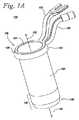
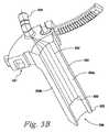
図1Aおよび1Bは、外科処置の実行の間、手術部位へのアクセスおよび照明の双方を提供するための本発明の例示的実施形態である、照明付き外科用アクセスシステムの異なる斜視図を例示している。例示的な照明付き外科用アクセスシステム110は、実質的に中空の管状本体を具備するアクセス装置120として例示される、手術部位にアクセスするためのポート、および、手術部位を照明するための、外科用アクセス装置120の遠位端部123近傍の側壁124に一体化された発光器130を含む。 1A and 1B illustrate different perspective views of an illuminated surgical access system that is an exemplary embodiment of the present invention for providing both access and illumination to a surgical site during the performance of a surgical procedure. ing. An exemplary illuminated
例示的アクセス装置120は、標準的なアクセスポートであってよく、患者の身体への挿入、および/または患者の身体に隣接しての設置に適した中空の管状本体を具備するカニューレの形状であってよい。例示的アクセス装置120は、アクセス装置の開口した近位端部121から、アクセス装置の開口した遠位端部123まで延びる内部通路122を画定する、少なくとも1つの中空の導管または管腔を有する。通路122は、管状本体の遠位端部123に隣接した手術部位、または、遠位端部123の周辺の手術部位にアクセスするための作業導管、または、作業導管の少なくとも一部を形成してよい。例示的実施形態では、アクセス装置120の本体は、内部通路122の近位ポート125を形成する開口した近位端部121を含み、開口した遠位端部123は、内部通路122の遠位ポート127を形成して、手術部位へのアクセスを可能としている。当業者であれば認識するであろうが、アクセス装置120は、身体の領域へのアクセスを提供するための任意の適切な構成および寸法を有してよい。例示的アクセス装置は、手術部位から軟組織を離して保持するために、ならびに/または、手術器具、装置、および/もしくはインプラントをガイドするために、用いられてよいが、当業者であれば、アクセス装置は、照明を必要とする通路または導管を画定する任意の適切な装置を具備してよいことを、認識するであろう。 The
示されるように、例示的アクセス装置110の管状本体は、滑らかな内側表面および外側表面を有するのが好ましい、円筒形側壁124によって形成されるが、当業者であれば、管状本体は、任意の寸法、形状、構成および数の側壁を有し得ることを、認識するであろう。アクセス装置は、手術部位へのアクセスを提供するためのポートを画定する、任意の適切な装置であり得る。アクセス装置は、任意の適切な断面を有することができ、また、例示的実施形態に示される円筒形の断面に制限されるわけではない。アクセス装置は、アクセス装置を通る開口または閉鎖した通路を画定するように、開口または閉鎖され得る。 As shown, the tubular body of the
外科用アクセス装置120は、プラスチック、外科用ステンレス鋼、および当業界で既知の他の材料など、これらに限定されることなく、任意の適切な外科用材料から形成され得る。適切な材料の例は、不透明ポリエーテルエーテルケトン(PEEK)または他の不透明プラスチックであるが、他の材料もまた使用されてよい。外科用アクセス装置はまた、不透明PEEKおよび外科用ステンレス鋼など、適切な材料の組み合わせで作成されてもよい。
例示的アクセス装置の管状本体は、剛性、半剛性、または可撓性とすることができ、また、作業導管および/または手術部位へのアクセスを画定するのに適した任意の適切な寸法、形状および構成を有し得る。例示的実施形態では、管状本体は、管状本体を通る直線的な導管を画定するよう、直線的であるが、当業者であれば、管状本体は、管状本体を通る成形された軌道(shaped trajectory)を画定してよいことを、認識するであろう。管状本体は、閉鎖した側壁を有する管状構造に制限されることはなく、開口した導管または固体部材を含む、通路を画定する任意の構成要素であり得る。いくつかの実施形態では、アクセス装置は、アクセス装置120の位置を固定するためのアームに、アクセス装置120を取り付けるための手段132を有してよい。 The tubular body of the exemplary access device can be rigid, semi-rigid, or flexible, and any suitable size, shape suitable for defining access to the working conduit and / or surgical site. And may have a configuration. In an exemplary embodiment, the tubular body is straight so as to define a straight conduit through the tubular body, but those skilled in the art will recognize that the tubular body is a shaped trajectory through the tubular body. ) May be defined. The tubular body is not limited to a tubular structure having closed side walls and can be any component that defines a passageway, including an open conduit or solid member. In some embodiments, the access device may have means 132 for attaching the
アクセス装置を通る通路は、さらに、または、代わりに、錐、骨タップ(bone taps)、閉塞具、ドリル、ガイドワイヤ、ならびに/または、ネジ、融合装置、人工椎間板および股関節ステムなどのインプラントなど、選択される手術器具を受容するよう構成された作業導管を、通路の長さ方向軸に沿って、形成してよい。 The passage through the access device may additionally or alternatively include cones, bone taps, obturators, drills, guide wires, and / or implants such as screws, fusion devices, artificial discs and hip stems, etc. A working conduit configured to receive the selected surgical instrument may be formed along the longitudinal axis of the passage.
一実施形態では、照明付きアクセス装置110は、作業導管に沿って器具をガイドするよう構成されてよい。このような実施形態では、管状本体の内径は、管状本体によってガイドされる器具の外径よりもわずかに大きくてよく、よって、器具は、管状本体に挿入されることができ、同時に管状本体の側壁は、患者に対して所定の角度で器具を維持する。代わりに、管状本体によってガイドされる器具は、管状本体に対しスライドする際に、管状本体が器具の向きを維持した状態で、管状本体を覆うようにスライドするよう構成され得る。この実施形態では、管状本体は、器具の内径よりもわずかに小さい外径を有し得る。しかしながら、アクセス装置110は、器具のための軌道を形成したり、器具をガイドしたりする必要はなく、手術部位へのアクセスを提供するのに適した任意の装置であり得る。 In one embodiment, the
ある実施形態では、近位ポート125を形成する近位端部121は、アクセス装置110を用いる外科医に対する眩輝を減少させるために、オーバーヘッドライトの反射を最小化するよう構成されてよい。一例では、図1Aに見られるように、近位ポート125の縁部128は、オーバーヘッドライトが外科医の目に照り返すのを防ぐように面取りされる(chamfered)。別の実施形態では、近位端部の表面は、表面を非反射性にするよう、処理されてよい。例えば、表面は、反射を減少させるように、エッチング、非反射性被覆物による被覆、または、別様の表面仕上げを施されてよい。これらは、可能な構成のうちのいくつかであり、他の実施、または、上記の組み合わせも可能であることが理解されよう。 In certain embodiments, the
発光器130は、アクセス装置120の遠位端部123において側壁124に一体化される。好ましくは、発光器130は、遠位端部123の内側および内側円周のあたりに、または、内側円周の少なくとも重要な(substantial)部分のあたりに直接的に、アクセス装置120の内部へと、周辺光を発する。例えば、開口した側部を有するアクセス装置については、発光器130は、側壁の周長に沿うあたりに光を当ててよく、また、アクセス装置の側壁が開口している所に光を当てても、当てなくてもよい。同様に、弧形のアクセス装置については、内側円周とは、弧の内側エッジを指し、完全な円または環である必要はない。管内部に発せられる光は、通路122を通り、遠位ポート127を出て、遠位ポート127に隣接した作業空間内へと、向けられる。 The
本発明の例示的実施形態である外科用アクセスシステムの一体型発光器130は、光を生じさせるための任意の適切な手段を具備することができ、この発光器は、アクセス装置の管状本体に直接一体化されてよい。一体型発光器は、扱いにくいケーブルを必要とすることなく、外科用アクセス装置に容易に照明を一体化させ、同時に、目的の場所への光の方向付けを可能とする。一体型発光器は、外科用アクセス装置の側壁に組み込まれるので、作業領域を損なわせたり、減少させたりせず、外科用アクセス装置の内部を妨げのない状態に保つ。一体型光源は、外科用アクセス装置の周囲あたり、好ましくは、外科用アクセス装置の内部に当てられる、均一な周辺光を提供することによって、優れた照明を提供する。 An exemplary embodiment of the present invention, an
好ましくは、発光器130は、アクセス装置120の遠位先端部126からオフセットしているか、または引込んでいる。アクセス装置120の遠位端部123は、患者に挿入され、側壁124は、手術部位から組織を離しておくために用いられて、外科医にアクセスを提供する。遠位端部123は、アクセスが所望される場所として配置されるので、アクセス装置120の遠位先端部126は、遠位先端部126に配される発光器130の照明を覆うか、または別様に遮り得る組織に直接接触してよい。発光器130をオフセットさせることは、組織または他の生物学的要素が、光の伝送を遮るか、または別様に照明に干渉する可能性を減少させる。オフセットHは、約1から約30の間、より好ましくは約10から約20mmの間であり、典型的な一実施形態では、約15mmである。本開示の利点を考慮すれば、他の可能な構成が、当業者には明らかであろう。 Preferably, the
いくつかの実施形態では、発光器130は、遠位ポート127の特定の点に光を集中させるよう構成されてよい。他の実施形態では、発光器130は、緩和された周囲の光を手術部位に渡って提供するよう構成されてよい。本開示の利点を考慮すれば、他の可能な実施および構成が、当業者には明らかであろう。 In some embodiments, the
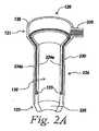
ある実施形態では、発光器130は、例えば連結器135を介して受容される光をアクセス装置120の近位端部121から装置の遠位端部123に伝送するための光伝送媒体230を具備する。一例では、図2Aに示されるように、光伝送媒体230は、光ファイバーケーブルである。この実施形態では、光伝送媒体230(この場合は光ファイバー)は、アクセス装置120の側壁124の内側表面224aと外側表面224bとの間に配列される。 In certain embodiments, the
側壁の内側表面224aと外側表面224bとの間に伝送媒体230を配列することは、伝送媒体の保護を提供する。このことを表したアクセス装置の断面の拡大図を図2Bに見ることができる。ある実施形態では、内側表面224aおよび外側表面224bは、異なる材料で作成されてよい。例えば、外側表面224bは、耐久性のため金属で作成されてよく、一方、内側層224aは、ポリマーなどの非伝導性または非反応性材料で作成されてよい。同じく、遠位端部226は、異なる材料で作成されてよい。例えば、遠位端部226は手術部位に接触するので、より軟質の材料または非反応性の材料で遠位端部226が作成されるようにすることが有益であり得る。適切な材料の例は上記に示されており、本開示の利点を考慮すれば、他の実施形態が、当業者には明らかであろう。典型的な一実施形態では、遠位端部は、PEEKおよび/または他の適切なポリマーから構築される。内側表面224aおよび外側表面224bは、外科用ステンレス鋼または他の適切な金属から構築される。典型的な一実施形態の遠位端部226は、内側表面224aおよび外側表面224bとは別個に製造されることができ、例えば、スナップ止め、ネジ、接着、または他の従来の接続機構によって、内側表面224aおよび外側表面224bに接続され得る。 Arranging the
図2Cは、アクセス装置120の図であり、遠位端部226からオフセットした周辺光光源130を提供するための、側壁124の周囲周りの伝送媒体230(この場合は光ファイバー)の分布を示している。ここで、伝送媒体230は、アクセス装置の遠位端部123に発光器130を提供するように、内側通路122内で終端している。伝送媒体230(この場合は光ファイバー)がどのように終端するかによって、発光器130は集中または緩和を提供してよい。他の伝送媒体および構成が可能であり、本開示の利点を考慮すれば、他の伝送媒体および構成が当業者には明らかであろうことが、理解されるべきである。 FIG. 2C is a diagram of the
光伝送器は、光源(不図示)に連結された光転送ケーブル(不図示)を受容するよう、アクセス装置の近位端部121に構成される。図2Aおよび2Cの例では、光ファイバーは、光転送ケーブルを介して光源に接続するよう、連結器135の235で相互に束ねられる。このような実施形態では、外部の光源は、アクセス装置の連結器135に光を提供するよう用いられてよく、この光は、伝送媒体を介して近位端部121から遠位端部123に伝送される。光源は、ハロゲンライトボックス、白熱光ライトボックス、および、ニューヨーク州スカネアトレス・フォールズのWelch Allyn Medical Productsから入手可能な光源など、ほとんどの病院環境において容易に利用可能なその他の光源を限定せずに含む、光を生じさせるための任意の適切な装置であってよい。光源は、任意の適切な出力レベルを有してよい。例示的実施形態では、光源は、300ワットハロゲンライトボックスである。光ファイバーケーブルまたは他の任意の適切な光伝送器であってよい光転送ケーブルを介して発光器130に伝送される光を生じさせることの出来る任意の他の適切な光源もまた、用いられてよい。 The optical transmitter is configured at the
上記例では、発光器130は、白光を発する。いくつかの実施では、他の種類の光を提供することが有益となり得ることが理解されよう。例えば、一実施形態では、発光器130は、赤外(IR)光または紫外(UV)光を発してよく、これらの光は、IRマーカーまたはUVマーカーを照射するか、または、IR反応性もしくはUV反応性のエポキシ樹脂もしくは接着剤を硬化させてよい。本開示の利点を考慮すれば、他の可能な実施または適用が、当業者には明らかであろう。 In the above example, the
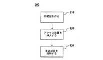
図3は、本発明を用いて手術部位を準備する方法の典型的な実施形態の流れ図300を表している。第1のステップは、患者に切開部を作ることを伴う(ステップ310)。一旦切開部が作られたら、本発明のアクセス装置が、切開部に挿入されてよい(ステップ320)。次に、手術部位が、アクセス装置を用いて照射されてよい(ステップ330)。これらステップは、以下に、より詳しく論じられる。 FIG. 3 depicts a
いくつかの実施形態では、方法は、患者の表皮に第1切開部を作ること、および、次に、従来の任意のやり方で、通路を作るために皮下組織の一部に切開部を広げることを含む。例えば、切開部は、拡張法(dilation)によって、複数の拡張器(dilators)を用いて所望の形状および方向に広げられ得る。一旦、切開部が所望の大きさ、形状および方向に広げられたら、開創器が挿入されてよい。 In some embodiments, the method creates a first incision in the patient's epidermis, and then extends the incision to a portion of the subcutaneous tissue to create a passageway in any conventional manner. including. For example, the incision can be dilated into a desired shape and orientation using a plurality of dilators by dilation. Once the incision has been expanded to the desired size, shape and orientation, a retractor may be inserted.
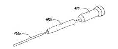
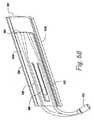
図4の実施形態では、アクセス装置120を挿入するための切開部を準備するために、連続的な拡張法が用いられる。よって、一連の拡張器405a、405bが、切開部(不図示)を通して患者に挿入されてよい。次に、アクセス装置120が、拡張器405a、405bを覆うようにして患者に挿入されてよい。アクセス装置120内を通る拡張器405a、405bは、アクセス装置120の挿入のためのガイドとして働く。 In the embodiment of FIG. 4, a continuous dilation method is used to prepare an incision for inserting the
上記実施形態は、典型的な例であることが理解されるべきである。異なる挿入器具に加え、挿入器具を用いた、または用いない、他の可能な挿入技術も実行可能である。本開示の利点を考慮すれば、他の実施および構成が、当業者には明らかであろう。 It should be understood that the above embodiments are typical examples. In addition to different insertion tools, other possible insertion techniques with or without insertion tools are also feasible. Other implementations and configurations will be apparent to those skilled in the art given the benefit of this disclosure.
一旦、アクセス装置120が挿入されたら、次に、手術部位が照明されてよい。いくつかの実施形態では、手術部位への照明は、光転送ケーブル150を介してアクセス装置を外部光源152に接続すること、ならびに、図1および2に表されるように、側壁に組み込まれた発光器130から、外部光源152からの光を伝送することを伴ってよい。 Once the
別の実施形態では、アクセス装置510は、図5Aに示されるように、開創器520であってよい。ここでは、開創器520は、手術部位へアクセスするためのポートを形成する、ブレードを貫く内部通路522を画定する、調節可能な1つまたは複数のブレード520、および、開創器によってアクセスされる手術部位を照明するための、開創器の、調節可能な1つまたは複数のブレード520の遠位端部に一体化される発光器530を具備する。 In another embodiment, the access device 510 may be a retractor 520, as shown in FIG. 5A. Here, retractor 520 defines one or more adjustable blades 520 that define an
図5Aの開創器520は、開創器520の開口した近位端部521から、開創器520の開口した遠位端部523に延びる内部通路522を有する。通路522は、管状本体の遠位端部523に隣接した手術部位、または、遠位端部523の周辺の手術部位にアクセスするための作業導管、または、作業導管の少なくとも一部を形成してよい。例示的実施形態では、開創器520の本体は、内部通路522の近位ポート525を形成する開口した近位端部521を含み、開口した遠位端部523は、内部通路522の遠位ポート527を形成して、手術部位へのアクセスを可能としている。当業者であれば認識するであろうが、開創器520は、身体の領域へのアクセスを提供するための任意の適切な構成および寸法を有してよい。 The retractor 520 of FIG. 5A has an
発光器530は、開創器520の遠位端部523においてブレード524に一体化される。好ましくは、発光器530は、遠位端部523の内側および内側円周のあたりに、または内側円周の少なくとも重要な部分のあたりに直接的に、開創器520の内部へと光を発する。内部に発せられる光は、通路522を通り、遠位ポート527を出て、遠位ポート527に隣接した作業空間内へと、向けられる。 The
好ましくは、発光器530は、開創器520の遠位先端部526からオフセットしているか、または引込んでいる。開創器520の遠位端部523は、患者に挿入され、ブレード524は、手術部位から組織を離しておくために用いられて、外科医にアクセスを提供する。遠位端部523は、アクセスが所望される場所として配置されるので、アクセス装置520の遠位先端部526は、遠位先端部526に配される発光器530の照明を覆うか、または別様に遮り得る組織に直接接触してよい。発光器530をオフセットさせることは、組織または他の生物学的要素が、光の伝送を遮るか、または別様に照明に干渉する可能性を減少させる。オフセットは、約1から約30mmの間、より好ましくは、約10から約20mmの間であり、典型的な一実施形態では、約15mmである。本開示の利点を考慮すれば、他の可能な構成が、当業者には明らかであろう。 Preferably, the
図5Bは、開創器520のブレード524の一実施形態を表している。この例では、ブレード524は、内側表面524aおよび外側表面524bを具備し、光伝送通路を提供する、光ファイバーケーブルなどの伝送媒体532を有する。伝送媒体532は、図1に示されるように、外部光源にブレードを接続するための、近位端部521に設けられた接続部535をさらに具備する。光伝送媒体532は、発光器530の遠位端部523で終端する。この実施形態では、発光器530がブレード524の遠位先端部526からオフセットしている様子が、見られる。 FIG. 5B represents one embodiment of the
図6Aは、別の実施形態の開創器620を表しており、調節可能なブレード624は、入れ子式にはまり込み(telescoping)、また、アクセス周りで回転し得る(rotate about an access)。図5Aの開創器520と同様に、図6Aの開創器620は、開創器620の開口した近位端部621から、開創器620の開口した遠位端部623に延びる、内部通路622を有する。通路622は、管状本体の遠位端部623に隣接した手術部位、または、遠位端部623の周辺の手術部位にアクセスするための作業導管、または、作業導管の少なくとも一部を形成してよい。例示的実施形態では、開創器の調節可能なブレード624は、より広い作業領域を作るよう患者において配備され得るように、外方向に、または「内向き(toed-in)」に、回転されている。回転可能であることに加え、本例における調節可能なブレードは、入れ子式にはまり込み、よって、調節可能なブレード624の遠位端部626は、延ばされたり引き込まれたりし、ブレードの調節可能な奥行きを備える。当業者であれば認識するであろうが、開創器620は、身体の領域へのアクセスを提供するための、任意の適切な構成および寸法を有してよい。 FIG. 6A depicts another embodiment of
発光器630は、開創器620の遠位端部623においてブレード624に一体化される。好ましくは、発光器630は、遠位端部623の内側および内側円周あたりに、または、内側円周の少なくとも重要な部分のあたりに直接的に、開創器620の内部へと、開創器ブレード624により画定される作業空間に光を発する。 The
好ましくは、発光器630は、開創器ブレード624の遠位先端部626からオフセットしているか、または引込んでいる。開創器620の遠位端部623は、患者に挿入され、ブレード624は、組織を手術部位から離しておくために用いられて、外科医にアクセスを提供する。遠位端部623は、アクセスが所望される場所として配置されるので、アクセス装置620の遠位先端部626は、遠位先端部626に配される発光器630の照明を覆うか、または別様に遮り得る組織に直接接触してよい。発光器630をオフセットさせることは、組織または他の生物学的要素が、光の伝送を遮るか、または別様に照明に干渉する可能性を減少させる。オフセットは、約1から約30mmの間、より好ましくは、約10から約20mmの間であり、典型的な一実施形態では、約15mmである。本開示の利点を考慮すれば、他の可能な構成が、当業者には明らかであろう。 Preferably, the
図6Bは、開創器620の入れ子式ブレード624の一実施形態を表している。この例では、ブレード624は、内側表面624aおよび外側表面624bを具備し、光伝送通路を提供する、光ファイバーケーブルなどの伝送媒体632を有する。伝送媒体632は、外部光源にブレード624を接続するための、近位端部621に設けられた連結器635などの接続部をさらに具備する。光伝送媒体632は、発光器630の遠位端部623で終端する。この実施形態では、発光器630がブレード624の遠位先端部626からオフセットしている様子が、見られる。図6Bの典型的なブレード624は、開創器組立体620の表面構成部642に係合するための構成部640をさらに含み、ブレード624が開創器組立体620に取り付けられると、ブレード624は調節可能に入れ子式にはまり込むことが可能となっている。 FIG. 6B represents one embodiment of the
例では、伝送媒体630は、アクセス装置の遠位端部123に発光器130を提供して、終端している。伝送媒体230(この場合は光ファイバー)が、どのように終端するかによって、発光器130は、集中させた光、または緩和させた光を提供してよい。他の伝送媒体および構成が可能であり、本開示の利点を考慮すれば、他の伝送媒体および構成が当業者には明らかであろうことが、理解されるべきである。 In the example, the
図5A、5B、6Aおよび6Bに表された開創器は、単に、開創器に可能ないくつもの構成の数例であることが、理解されるべきである。本開示の利点を考慮すれば、一体型発光器を組み込んだ他の可能な構成が、当業者には明らかであろう。 It should be understood that the retractor depicted in FIGS. 5A, 5B, 6A and 6B is merely a few examples of the number of configurations possible for a retractor. Other possible configurations incorporating an integrated light emitter will be apparent to those skilled in the art in view of the advantages of the present disclosure.
図7は、本発明を用いて手術部位を準備する方法の典型的な一実施形態の流れ図700を表している。方法は、患者に切開部を作るステップ710、切開部に本発明の開創器を挿入するステップ720、および開創器で手術部位を照明するステップ730を伴う。 FIG. 7 depicts a
アクセス装置を用いることに関して上記で論じられる切開および連続的な拡張法の技術は、開創器の使用にも同等に適用される。開創器の利点は、挿入後に、開創器が切開部をさらに拡張し組織を引込めるために用いられ、手術部位へのより大きなアクセスを提供し得ることである。 The incision and continuous dilation technique discussed above with respect to using an access device is equally applicable to the use of a retractor. The advantage of the retractor is that, after insertion, the retractor can be used to further expand the incision and retract tissue, providing greater access to the surgical site.
本発明は、例示的実施形態に関して説明されている。ある変更が、本発明の範囲を逸脱することなく上記の構築において、なされてよく、よって、上記説明に含まれるか、または添付図面に示される全ての事柄は、例示的なものであり制限的な意味はないと解釈されることが、意図されている。 The invention has been described with reference to exemplary embodiments. Certain changes may be made in the above construction without departing from the scope of the present invention, so that all matter contained in the above description or shown in the accompanying drawings is illustrative and restrictive. It is intended to be interpreted as meaningless.
また、特許請求の範囲は、本明細書で説明される発明のあらゆる包括的特徴および限定的特徴、ならびに、用語上それらに帰属すると言ってもよい、本発明の範囲のあらゆる記述に及ぶことが理解されなければならない。 Also, the claims extend to all generic and limiting features of the invention described herein, as well as any description of the scope of the invention that may be termed to be attributed to them. Must be understood.
〔実施の態様〕
(1)手術の間に患者へのアクセスを提供するための照明付き外科用アクセスシステムにおいて、
外科用アクセス装置であって、少なくとも1つの側壁を具備しており、前記患者へアクセスするためのポートを形成する、前記外科用アクセス装置を貫く内部通路を画定している、外科用アクセス装置と、
前記外科用アクセス装置によってアクセスされる手術部位を照明するための、前記アクセス装置の遠位端部近傍の前記側壁に一体化された発光器と、
を具備する、外科用アクセスシステム。
(2)実施態様1に記載の外科用アクセスシステムにおいて、
前記発光器は、前記アクセス装置の前記遠位端部からオフセットした前記側壁に一体化される、外科用アクセスシステム。
(3)実施態様1に記載の外科用アクセスシステムにおいて、
前記発光器は、前記アクセス装置の前記遠位端部における前記ポートの前記内部通路の周長に沿って照明を提供する、外科用アクセスシステム。
(4)実施態様1に記載の外科用アクセスシステムにおいて、
前記発光器は、前記アクセス装置の近位端部から、前記装置の前記遠位端部に、光を伝送するための光伝送媒体を具備する、外科用アクセスシステム。
(5)実施態様4に記載の外科用アクセスシステムにおいて、
前記光伝送媒体は、前記アクセス装置の前記側壁の不伝導性の内側表面と不伝導性の外側表面との間に配列される、外科用アクセスシステム。
(6)実施態様4に記載の外科用アクセスシステムにおいて、
前記光伝送媒体は、光ファイバーケーブルを具備する、外科用アクセスシステム。
(7)実施態様6に記載の外科用アクセスシステムにおいて、
前記光ファイバーケーブルは、前記アクセス装置によって形成される前記ポート内の特定の場所において光を集中させるように終端する、外科用アクセスシステム。
(8)実施態様6に記載の外科用アクセスシステムにおいて、
前記光ファイバーケーブルは、前記アクセス装置によって形成される前記ポート内の特定の場所において光を拡散させるように終端する、外科用アクセスシステム。
(9)実施態様4に記載の外科用アクセスシステムにおいて、
前記光伝送媒体は、前記近位端部において、光源に連結された光転送ケーブルを受容するように構成される、外科用アクセスシステム。
(10)実施態様1に記載の外科用アクセスシステムにおいて、
前記発光器は、赤外光を伝送するよう構成される、外科用アクセスシステム。Embodiment
(1) In an illuminated surgical access system for providing access to a patient during surgery,
A surgical access device comprising at least one sidewall and defining an internal passage through the surgical access device that defines a port for accessing the patient; ,
A light emitter integrated in the side wall near the distal end of the access device for illuminating a surgical site accessed by the surgical access device;
Surgical access system comprising:
(2) In the surgical access system according to embodiment 1,
The surgical access system, wherein the light emitter is integrated into the sidewall offset from the distal end of the access device.
(3) In the surgical access system according to embodiment 1,
The surgical access system, wherein the light emitter provides illumination along a circumference of the internal passage of the port at the distal end of the access device.
(4) In the surgical access system according to embodiment 1,
The surgical access system, wherein the light emitter comprises an optical transmission medium for transmitting light from a proximal end of the access device to the distal end of the device.
(5) In the surgical access system according to embodiment 4,
The surgical access system, wherein the optical transmission medium is arranged between a non-conductive inner surface and a non-conductive outer surface of the sidewall of the access device.
(6) In the surgical access system according to embodiment 4,
The surgical access system, wherein the optical transmission medium comprises a fiber optic cable.
(7) In the surgical access system according to embodiment 6,
The surgical access system, wherein the fiber optic cable terminates to concentrate light at a specific location within the port formed by the access device.
(8) In the surgical access system according to embodiment 6,
The surgical access system, wherein the fiber optic cable terminates to diffuse light at a specific location within the port formed by the access device.
(9) In the surgical access system according to embodiment 4,
The surgical access system, wherein the optical transmission medium is configured to receive an optical transfer cable coupled to a light source at the proximal end.
(10) The surgical access system according to embodiment 1,
The surgical access system, wherein the light emitter is configured to transmit infrared light.
(11)実施態様1に記載の外科用アクセスシステムにおいて、
前記発光器は、紫外光を伝送するよう構成される、外科用アクセスシステム。
(12)実施態様1に記載の外科用アクセスシステムにおいて、
前記アクセス装置の近位端部は、外部光の反射を最小化するよう構成される、外科用アクセスシステム。
(13)患者の手術部位にアクセスする方法において、
前記患者に切開部を作るステップと、
前記患者の前記切開部に外科用アクセス装置を挿入するステップであって、前記外科用アクセス装置は、
前記患者にアクセスするためのポートを形成する、前記アクセス装置を貫く内部通路を画定する少なくとも1つの側壁、および
前記外科用アクセス装置によってアクセスされる手術部位を照明するための、前記アクセス装置の遠位端部近傍の前記側壁に一体化された発光器、
を具備する、外科用アクセス装置を挿入するステップと、
前記外科用アクセス装置を用いて前記手術部位を照明するステップと、
を含む、方法。
(14)実施態様13に記載の方法において、
前記手術部位は、前記患者の背骨へのアクセスを提供する、方法。
(15)実施態様13に記載の方法において、
1つまたは複数の拡張器は、前記切開部を通して挿入され、前記アクセス装置は、前記1つまたは複数の拡張器を覆うように挿入される、方法。
(16)実施態様13に記載の方法において、
前記手術部位を照明することは、前記アクセス装置を外部の光源に接続すること、および、前記側壁に組み込まれた前記発光器から、前記外部の光源からの光を伝送することを含む、方法。
(17)手術の間に患者の手術部位へのアクセスを提供するための照明付き外科用アクセスシステムにおいて、
前記手術部位にアクセスするための、前記アクセスシステムを貫く内部通路を画定する、調節可能な1つまたは複数のブレードを具備する開創器と、
前記開創器によってアクセスされる手術部位を照明するための、前記開創器の前記調節可能な1つまたは複数のブレードの遠位端部近傍の一体型発光器と、
を具備する、外科用アクセスシステム。
(18)実施態様17に記載の外科用開創器において、
前記調節可能な1つまたは複数のブレードは、入れ子式のブレードを具備する、外科用開創器。
(19)実施態様17に記載の外科用アクセスシステムにおいて、
前記発光器は、前記調節可能な1つまたは複数のブレードの前記遠位端部からオフセットした前記側壁に一体化される、外科用アクセスシステム。
(20)実施態様17に記載の外科用アクセスシステムにおいて、
前記発光器は、前記1つまたは複数のブレードの近位端部から、前記1つまたは複数のブレードの前記遠位端部に、光を伝送するための光伝送媒体を具備する、外科用アクセスシステム。(11) In the surgical access system according to embodiment 1,
The surgical access system, wherein the light emitter is configured to transmit ultraviolet light.
(12) In the surgical access system according to embodiment 1,
The surgical access system, wherein the proximal end of the access device is configured to minimize reflection of external light.
(13) In a method of accessing a surgical site of a patient,
Making an incision in the patient;
Inserting a surgical access device into the incision of the patient, the surgical access device comprising:
A distance of the access device to illuminate a surgical site accessed by the surgical access device and at least one side wall defining an internal passage through the access device forming a port for accessing the patient A light emitter integrated with the side wall near the edge,
Inserting a surgical access device comprising:
Illuminating the surgical site using the surgical access device;
Including a method.
(14) In the method according to embodiment 13,
The method wherein the surgical site provides access to the patient's spine.
(15) In the method according to embodiment 13,
The method wherein one or more dilators are inserted through the incision and the access device is inserted over the one or more dilators.
(16) In the method according to embodiment 13,
Illuminating the surgical site includes connecting the access device to an external light source and transmitting light from the external light source from the light emitter incorporated in the sidewall.
(17) In an illuminated surgical access system for providing access to a patient's surgical site during surgery;
A retractor comprising one or more adjustable blades defining an internal passage through the access system for accessing the surgical site;
An integrated light emitter near the distal end of the adjustable one or more blades of the retractor for illuminating a surgical site accessed by the retractor;
Surgical access system comprising:
(18) The surgical retractor according to embodiment 17,
The surgical retractor, wherein the adjustable one or more blades comprise a telescoping blade.
(19) The surgical access system according to embodiment 17,
The surgical access system, wherein the light emitter is integrated into the sidewall offset from the distal end of the adjustable one or more blades.
(20) The surgical access system according to embodiment 17,
Surgical access comprising a light transmission medium for transmitting light from a proximal end of the one or more blades to the distal end of the one or more blades system.
(21)実施態様17に記載の外科用アクセスシステムにおいて、
前記光伝送媒体は、前記開創器の前記ブレードの不伝導性の内側表面と、不伝導性の外側表面との間に配列される、外科用アクセスシステム。
(22)実施態様17に記載の外科用アクセスシステムにおいて、
前記光伝送媒体は、光ファイバーケーブルを具備する、外科用アクセスシステム。
(23)実施態様17に記載の外科用アクセスシステムにおいて、
前記発光器は、赤外光を伝送するよう構成される、外科用アクセスシステム。
(24)実施態様17に記載の外科用アクセスシステムにおいて、
前記発光器は、紫外光を伝送するよう構成される、外科用アクセスシステム。
(25)実施態様17に記載の外科用開創器において、
前記開創器の近位端部は、外部光の反射を最小化するよう構成される、外科用開創器。
(26)患者の手術部位にアクセスする方法において、
前記患者に切開部を作るステップと、
前記患者の前記切開部に開創器を挿入するステップであって、前記開創器は、
前記患者にアクセスするための、開創器を貫く内部通路を定める調節可能な1つまたは複数のブレード、および
前記開創器によってアクセスされる手術部位を照明するための、前記開創器の、前記調節可能な1つまたは複数のブレードの遠位端部近傍の一体型発光器、
を具備する、開創器を挿入するステップと、
前記開創器を用いて前記手術部位を照明するステップと、
を含む、方法。(21) The surgical access system according to embodiment 17,
The surgical access system, wherein the optical transmission medium is arranged between a non-conductive inner surface and a non-conductive outer surface of the blade of the retractor.
(22) The surgical access system according to embodiment 17,
The surgical access system, wherein the optical transmission medium comprises a fiber optic cable.
(23) The surgical access system according to embodiment 17,
The surgical access system, wherein the light emitter is configured to transmit infrared light.
(24) The surgical access system according to embodiment 17,
The surgical access system, wherein the light emitter is configured to transmit ultraviolet light.
(25) The surgical retractor according to embodiment 17,
The surgical retractor, wherein the proximal end of the retractor is configured to minimize reflection of external light.
(26) In a method of accessing a surgical site of a patient,
Making an incision in the patient;
Inserting a retractor into the incision of the patient, the retractor comprising:
The adjustable one or more blades defining an internal passage through the retractor for accessing the patient, and the adjustable of the retractor for illuminating a surgical site accessed by the retractor An integrated light emitter near the distal end of the one or more blades;
Inserting a retractor comprising:
Illuminating the surgical site using the retractor;
Including a method.
Claims (22)
Translated fromJapanese外科用アクセス装置であって、少なくとも1つの側壁を具備しており、前記患者へアクセスするためのポートを形成する、前記外科用アクセス装置を貫く内部通路を画定している、外科用アクセス装置と、
前記外科用アクセス装置によってアクセスされる手術部位を照明するための、前記アクセス装置の遠位端部近傍の前記側壁に一体化された発光器と、
を具備する、外科用アクセスシステム。In a illuminated surgical access system for providing access to a patient during surgery,
A surgical access device comprising at least one sidewall and defining an internal passage through the surgical access device that defines a port for accessing the patient; ,
A light emitter integrated in the side wall near the distal end of the access device for illuminating a surgical site accessed by the surgical access device;
Surgical access system comprising:
前記発光器は、前記アクセス装置の前記遠位端部からオフセットした前記側壁に一体化される、外科用アクセスシステム。The surgical access system of claim 1, wherein
The surgical access system, wherein the light emitter is integrated into the sidewall offset from the distal end of the access device.
前記発光器は、前記アクセス装置の前記遠位端部における前記ポートの前記内部通路の周長に沿って照明を提供する、外科用アクセスシステム。The surgical access system of claim 1, wherein
The surgical access system, wherein the light emitter provides illumination along a circumference of the internal passage of the port at the distal end of the access device.
前記発光器は、前記アクセス装置の近位端部から、前記装置の前記遠位端部に、光を伝送するための光伝送媒体を具備する、外科用アクセスシステム。The surgical access system of claim 1, wherein
The surgical access system, wherein the light emitter comprises an optical transmission medium for transmitting light from a proximal end of the access device to the distal end of the device.
前記光伝送媒体は、前記アクセス装置の前記側壁の不伝導性の内側表面と不伝導性の外側表面との間に配列される、外科用アクセスシステム。The surgical access system of claim 4, wherein
The surgical access system, wherein the optical transmission medium is arranged between a non-conductive inner surface and a non-conductive outer surface of the sidewall of the access device.
前記光伝送媒体は、光ファイバーケーブルを具備する、外科用アクセスシステム。The surgical access system of claim 4, wherein
The surgical access system, wherein the optical transmission medium comprises a fiber optic cable.
前記光ファイバーケーブルは、前記アクセス装置によって形成される前記ポート内の特定の場所において光を集中させるように終端する、外科用アクセスシステム。The surgical access system of claim 6, wherein
The surgical access system, wherein the fiber optic cable terminates to concentrate light at a specific location within the port formed by the access device.
前記光ファイバーケーブルは、前記アクセス装置によって形成される前記ポート内の特定の場所において光を拡散させるように終端する、外科用アクセスシステム。The surgical access system of claim 6, wherein
The surgical access system, wherein the fiber optic cable terminates to diffuse light at a specific location within the port formed by the access device.
前記光伝送媒体は、前記近位端部において、光源に連結された光転送ケーブルを受容するように構成される、外科用アクセスシステム。The surgical access system of claim 4, wherein
The surgical access system, wherein the optical transmission medium is configured to receive an optical transfer cable coupled to a light source at the proximal end.
前記発光器は、赤外光を伝送するよう構成される、外科用アクセスシステム。The surgical access system of claim 1, wherein
The surgical access system, wherein the light emitter is configured to transmit infrared light.
前記発光器は、紫外光を伝送するよう構成される、外科用アクセスシステム。The surgical access system of claim 1, wherein
The surgical access system, wherein the light emitter is configured to transmit ultraviolet light.
前記アクセス装置の近位端部は、外部光の反射を最小化するよう構成される、外科用アクセスシステム。The surgical access system of claim 1, wherein
The surgical access system, wherein the proximal end of the access device is configured to minimize reflection of external light.
前記患者に切開部を作るステップと、
前記患者の前記切開部に外科用アクセス装置を挿入するステップであって、前記外科用アクセス装置は、
前記患者にアクセスするためのポートを形成する、前記アクセス装置を貫く内部通路を画定する少なくとも1つの側壁、および
前記外科用アクセス装置によってアクセスされる手術部位を照明するための、前記アクセス装置の遠位端部近傍の前記側壁に一体化された発光器、
を具備する、外科用アクセス装置を挿入するステップと、
前記外科用アクセス装置を用いて前記手術部位を照明するステップと、
を含む、方法。In a method for accessing a patient's surgical site,
Making an incision in the patient;
Inserting a surgical access device into the incision of the patient, the surgical access device comprising:
A distance of the access device to illuminate a surgical site accessed by the surgical access device and at least one side wall defining an internal passage through the access device forming a port for accessing the patient A light emitter integrated with the side wall near the edge,
Inserting a surgical access device comprising:
Illuminating the surgical site using the surgical access device;
Including a method.
前記手術部位にアクセスするための、前記アクセスシステムを貫く内部通路を画定する、調節可能な1つまたは複数のブレードを具備する開創器と、
前記開創器によってアクセスされる手術部位を照明するための、前記開創器の前記調節可能な1つまたは複数のブレードの遠位端部近傍の一体型発光器と、
を具備する、外科用アクセスシステム。In an illuminated surgical access system for providing access to a patient's surgical site during surgery,
A retractor comprising one or more adjustable blades defining an internal passage through the access system for accessing the surgical site;
An integrated light emitter near the distal end of the adjustable one or more blades of the retractor for illuminating a surgical site accessed by the retractor;
Surgical access system comprising:
前記調節可能な1つまたは複数のブレードは、入れ子式のブレードを具備する、外科用開創器。The surgical retractor according to claim 14,
The surgical retractor, wherein the adjustable one or more blades comprise a telescoping blade.
前記発光器は、前記調節可能な1つまたは複数のブレードの前記遠位端部からオフセットした前記側壁に一体化される、外科用アクセスシステム。The surgical access system of claim 14, wherein
The surgical access system, wherein the light emitter is integrated into the sidewall offset from the distal end of the adjustable one or more blades.
前記発光器は、前記1つまたは複数のブレードの近位端部から、前記1つまたは複数のブレードの前記遠位端部に、光を伝送するための光伝送媒体を具備する、外科用アクセスシステム。The surgical access system of claim 14, wherein
Surgical access comprising a light transmission medium for transmitting light from a proximal end of the one or more blades to the distal end of the one or more blades system.
前記光伝送媒体は、前記開創器の前記ブレードの不伝導性の内側表面と、不伝導性の外側表面との間に配列される、外科用アクセスシステム。The surgical access system of claim 14, wherein
The surgical access system, wherein the optical transmission medium is arranged between a non-conductive inner surface and a non-conductive outer surface of the blade of the retractor.
前記光伝送媒体は、光ファイバーケーブルを具備する、外科用アクセスシステム。The surgical access system of claim 14, wherein
The surgical access system, wherein the optical transmission medium comprises a fiber optic cable.
前記発光器は、赤外光を伝送するよう構成される、外科用アクセスシステム。The surgical access system of claim 14, wherein
The surgical access system, wherein the light emitter is configured to transmit infrared light.
前記発光器は、紫外光を伝送するよう構成される、外科用アクセスシステム。The surgical access system of claim 14, wherein
The surgical access system, wherein the light emitter is configured to transmit ultraviolet light.
前記開創器の近位端部は、外部光の反射を最小化するよう構成される、外科用開創器。The surgical retractor according to claim 14,
The surgical retractor, wherein the proximal end of the retractor is configured to minimize reflection of external light.
Applications Claiming Priority (2)
| Application Number | Priority Date | Filing Date | Title |
|---|---|---|---|
| US11/441,753US8430813B2 (en) | 2006-05-26 | 2006-05-26 | Illuminated surgical access system including a surgical access device and integrated light emitter |
| PCT/US2007/012614WO2007139993A2 (en) | 2006-05-26 | 2007-05-24 | Illuminated surgical access system including a surgical access device and integrated light emitter |
Publications (2)
| Publication Number | Publication Date |
|---|---|
| JP2009538196Atrue JP2009538196A (en) | 2009-11-05 |
| JP2009538196A5 JP2009538196A5 (en) | 2012-08-16 |
Family
ID=38750367
Family Applications (1)
| Application Number | Title | Priority Date | Filing Date |
|---|---|---|---|
| JP2009512181APendingJP2009538196A (en) | 2006-05-26 | 2007-05-24 | Illuminated surgical access system including a surgical access device and an integrated light emitter |
Country Status (6)
| Country | Link |
|---|---|
| US (2) | US8430813B2 (en) |
| EP (2) | EP2959825A1 (en) |
| JP (1) | JP2009538196A (en) |
| AU (1) | AU2007267794B2 (en) |
| CA (1) | CA2653713C (en) |
| WO (1) | WO2007139993A2 (en) |
Cited By (1)
| Publication number | Priority date | Publication date | Assignee | Title |
|---|---|---|---|---|
| JP2025507989A (en)* | 2022-04-14 | 2025-03-21 | アグロー メディカル テクノロジー カンパニー リミテッド | Method and system for surgical implant imaging - Patent application |
Families Citing this family (81)
| Publication number | Priority date | Publication date | Assignee | Title |
|---|---|---|---|---|
| US9387010B2 (en) | 2004-10-28 | 2016-07-12 | Nico Corporation | Surgical access assembly and method of using same |
| US9186175B2 (en)* | 2004-10-28 | 2015-11-17 | Nico Corporation | Surgical access assembly and method of using same |
| US9161820B2 (en)* | 2004-10-28 | 2015-10-20 | Nico Corporation | Surgical access assembly and method of using same |
| US9770261B2 (en) | 2004-10-28 | 2017-09-26 | Nico Corporation | Surgical access assembly and method of using same |
| US9265523B2 (en) | 2011-10-24 | 2016-02-23 | Nico Corporation | Surgical access system with navigation element and method of using same |
| US7510524B2 (en) | 2005-04-04 | 2009-03-31 | Invuity, Inc. | Optical waveguide sheath |
| US9005115B2 (en) | 2005-04-04 | 2015-04-14 | Invuity, Inc. | Illuminated telescoping cannula |
| US8251902B2 (en) | 2005-10-17 | 2012-08-28 | Lanx, Inc. | Pedicle guided retractor system |
| US8062217B2 (en) | 2007-01-26 | 2011-11-22 | Theken Spine, Llc | Surgical retractor with removable blades and method of use |
| US8202290B2 (en)* | 2007-04-17 | 2012-06-19 | Tyco Healthcare Group Lp | Visual obturator with handle |
| US20080319432A1 (en)* | 2007-06-20 | 2008-12-25 | Scott Ely | Surgical illumination system and method |
| US8192353B2 (en)* | 2007-10-05 | 2012-06-05 | Tyco Healthcare Group Lp | Visual obturator |
| USD632787S1 (en) | 2009-11-03 | 2011-02-15 | Intubrite, Llc | Laryngoscope handle |
| US8257250B2 (en)* | 2008-06-23 | 2012-09-04 | Intubrite, Llc | Laryngoscope and method of use |
| USRE48598E1 (en) | 2008-06-23 | 2021-06-22 | Salter Labs | Laryngoscope and method of use |
| US9072446B2 (en) | 2008-06-23 | 2015-07-07 | Intubrite, Llc | Laryngoscope and method of use |
| US8968186B2 (en) | 2008-06-23 | 2015-03-03 | Intubrite, Llc | Handle for fiber optic device |
| US8012087B2 (en)* | 2008-06-23 | 2011-09-06 | Intubrite, Llc | Laryngoscope blade and method of use |
| US20090318768A1 (en)* | 2008-06-23 | 2009-12-24 | Tenger James P | Laryngoscope and Method of Use |
| US9095298B2 (en) | 2008-06-23 | 2015-08-04 | Intubrite, Llc | Adjustable display mechanism and method |
| US8152719B2 (en)* | 2008-06-23 | 2012-04-10 | Intubrite, Llc | Laryngoscope and method of use |
| US20100114147A1 (en)* | 2008-10-30 | 2010-05-06 | The University Of Toledo | Directional soft tissue dilator and docking pin with integrated light source for optimization of retractor placement in minimally invasive spine surgery |
| US8992558B2 (en) | 2008-12-18 | 2015-03-31 | Osteomed, Llc | Lateral access system for the lumbar spine |
| USD608889S1 (en) | 2009-02-10 | 2010-01-26 | Intubrite, Llc | Laryngoscope |
| USD609808S1 (en) | 2009-02-10 | 2010-02-09 | Intubrite, Llc | Laryngoscope blade |
| USD611598S1 (en) | 2009-02-10 | 2010-03-09 | Intubrite, Llc | Laryngoscope handle |
| EP2494913B1 (en)* | 2009-10-26 | 2018-12-12 | B. J. Zh. F. Panther Medical Equipment Co., Ltd. | Anorectal surgical instrument and anal dilator |
| US8747309B2 (en)* | 2010-11-09 | 2014-06-10 | Covidien Lp | Suspension system for minimally invasive surgery |
| USD630739S1 (en) | 2009-12-21 | 2011-01-11 | Intubrite, Llc | Laryngoscope blade |
| USD630737S1 (en) | 2009-12-21 | 2011-01-11 | Intubrite, Llc | Laryngoscope blade |
| USD630738S1 (en) | 2009-12-21 | 2011-01-11 | Intubrite, Llc | Laryngoscope blade |
| USD634008S1 (en) | 2009-12-21 | 2011-03-08 | Intubrite, Llc | Laryngoscope blade |
| JP5535611B2 (en)* | 2009-12-22 | 2014-07-02 | 日本コヴィディエン株式会社 | Endoscope cover fixing tool |
| USD630742S1 (en) | 2009-12-23 | 2011-01-11 | Intubrite, Llc | Laryngoscope blade |
| USD630741S1 (en) | 2009-12-23 | 2011-01-11 | Intubrite, Llc | Laryngoscope blade |
| USD630744S1 (en) | 2009-12-23 | 2011-01-11 | Intubrite, Llc | Laryngoscope blade |
| USD630745S1 (en) | 2009-12-23 | 2011-01-11 | Intubrite, Llc | Laryngoscope blade |
| USD630740S1 (en) | 2009-12-23 | 2011-01-11 | Intubrite, Llc | Laryngoscope blade |
| USD630743S1 (en) | 2009-12-23 | 2011-01-11 | Intubrite, Llc | Laryngoscope blade |
| US8840546B2 (en) | 2010-06-01 | 2014-09-23 | The Board Of Trustees Of The Leland Stanford Junior University | System for accessing a body orifice |
| DE102010022403B4 (en)* | 2010-06-01 | 2018-12-06 | Geuder Aktiengesellschaft | Device for introducing a medium or an instrument into the human body |
| US9289114B2 (en)* | 2010-07-30 | 2016-03-22 | Nilesh R. Vasan | Disposable, self-contained laryngoscope and method of using same |
| USD656233S1 (en) | 2010-09-21 | 2012-03-20 | Tyco Healthcare Group Lp | Bladeless obturator member |
| USD654168S1 (en) | 2010-09-21 | 2012-02-14 | Tyco Healthcare Group Lp | Bladeless obturator member |
| USD655005S1 (en) | 2010-09-21 | 2012-02-28 | Tyco Healthcare Group Lp | Bladeless obturator member |
| CN102100528A (en)* | 2010-12-10 | 2011-06-22 | 广州宝胆医疗器械科技有限公司 | Integrated thermal-infrared scanning gastroscope system |
| CN102100542A (en)* | 2010-12-10 | 2011-06-22 | 广州宝胆医疗器械科技有限公司 | Integrated infrared heat-scanning cholecystoscope system |
| CN102100529B (en)* | 2010-12-10 | 2013-04-24 | 广州宝胆医疗器械科技有限公司 | Integrated infrared thermally scanning esophagoscope system |
| US9757109B2 (en) | 2010-12-10 | 2017-09-12 | Illumix Surgical Canada Inc. | Organic light emitting diode illuminated surgical retractor |
| CN102100539B (en)* | 2010-12-10 | 2013-04-24 | 广州宝胆医疗器械科技有限公司 | Integrated anorectaloscope system with infrared thermal scanning function |
| US20120321259A1 (en)* | 2011-06-14 | 2012-12-20 | Luke Lu | Light-transmittable composite tube |
| US10722318B2 (en)* | 2011-08-24 | 2020-07-28 | Mako Surgical Corp. | Surgical tools for selectively illuminating a surgical volume |
| IL215106A0 (en)* | 2011-09-12 | 2012-02-29 | Daniel Sherwin | Laparoscopic device |
| WO2013138449A1 (en)* | 2012-03-14 | 2013-09-19 | Armour Technologies, Inc. | Sterile site apparatus, system, and method of using the same |
| US9757147B2 (en) | 2012-04-11 | 2017-09-12 | Nico Corporation | Surgical access system with navigation element and method of using same |
| US9480855B2 (en) | 2012-09-26 | 2016-11-01 | DePuy Synthes Products, Inc. | NIR/red light for lateral neuroprotection |
| US9084591B2 (en) | 2012-10-23 | 2015-07-21 | Neurostructures, Inc. | Retractor |
| US20140121467A1 (en)* | 2012-10-31 | 2014-05-01 | Invuity, Inc. | Methods and apparatus for simultaneous retraction and distraction of bone and soft tissue |
| CN103126752B (en)* | 2013-01-31 | 2015-10-07 | 毛克亚 | The expansible channel system of novel high polymer material built-in LED light source vertebral column minimally invasive |
| CN103126751B (en)* | 2013-01-31 | 2015-10-07 | 毛克亚 | The expansible channel system of novel high polymer material built-in fiber vertebral column minimally invasive |
| US10178211B2 (en)* | 2013-06-06 | 2019-01-08 | Dolby Laboratories Licensing Corporation | Lighting for audio devices |
| CA3168236A1 (en)* | 2014-03-05 | 2015-09-11 | Nico Corporation | Surgical access assembly and method of using same |
| EP3145385A4 (en)* | 2014-05-22 | 2018-02-14 | Invuity, Inc. | Medical device featuring cladded waveguide |
| US10258228B2 (en) | 2014-08-08 | 2019-04-16 | K2M, Inc. | Retraction devices, systems, and methods for minimally invasive spinal surgery |
| CN104257344B (en)* | 2014-09-25 | 2016-09-21 | 李晓萍 | Gynecological examination device |
| US10245071B2 (en) | 2014-12-23 | 2019-04-02 | Michael Frank Gunter WOOD | System for illumination during a corridor based procedure |
| KR101616122B1 (en)* | 2015-03-10 | 2016-04-28 | 김현성 | Taylor tubular retractor |
| WO2017200555A1 (en)* | 2016-05-20 | 2017-11-23 | Choicespine, Lp | Access instruments to extend a surgical working channel |
| WO2018039228A1 (en) | 2016-08-23 | 2018-03-01 | Stryker European Holdings I, Llc | Instrumentation for the implantation of spinal implants |
| WO2019036048A2 (en) | 2017-08-17 | 2019-02-21 | Stryker European Holdings I, Llc | Lateral access bridges, shims and lighting including rod lighting |
| BR112020004978A2 (en)* | 2017-09-15 | 2020-09-15 | Oxular Limited | sterile lyophilized pharmacological composition, pharmaceutical formulation, unit dosage form, kit, method for treating an eye disease or condition, method for treating an eye disease or condition and pharmacological composition, pharmacological composition for use |
| EP3545857B1 (en) | 2018-03-30 | 2024-01-03 | Stryker European Operations Holdings LLC | Lateral access retractor and core insertion |
| USD876625S1 (en) | 2018-08-07 | 2020-02-25 | Adroit Surgical, Llc | Laryngoscope |
| US11413029B2 (en) | 2018-10-24 | 2022-08-16 | Stryker European Operations Holdings Llc | Anterior to psoas instrumentation |
| CA3127963A1 (en)* | 2019-02-08 | 2020-08-13 | Rebound Therapeutics Corporation | Lighted cannula system |
| US12342991B2 (en)* | 2019-07-31 | 2025-07-01 | Nico Corporation | Surgical access device with integrated illumination |
| WO2021053392A2 (en)* | 2019-09-20 | 2021-03-25 | Axis Spine Technologies Ltd. | Radiolucent surgical retractor |
| US11564674B2 (en) | 2019-11-27 | 2023-01-31 | K2M, Inc. | Lateral access system and method of use |
| WO2023163702A1 (en)* | 2022-02-24 | 2023-08-31 | Intersect ENT International GmbH | Illumination assembly for handheld medical devices and instruments |
| USD1076077S1 (en)* | 2023-04-25 | 2025-05-20 | Adam Isaac Lewis | Retractor tube |
| US20250072723A1 (en)* | 2023-08-30 | 2025-03-06 | Karl Storz Imaging, Inc. | Endoscopic Illumination Sleeve |
Citations (3)
| Publication number | Priority date | Publication date | Assignee | Title |
|---|---|---|---|---|
| US5957832A (en)* | 1993-10-08 | 1999-09-28 | Heartport, Inc. | Stereoscopic percutaneous visualization system |
| US20040143167A1 (en)* | 2002-08-02 | 2004-07-22 | Branch Charles L. | Systems and techniques for illuminating a surgical space |
| WO2005016131A2 (en)* | 2003-08-14 | 2005-02-24 | Hfsc Company | Multiple-blade retractor |
Family Cites Families (143)
| Publication number | Priority date | Publication date | Assignee | Title |
|---|---|---|---|---|
| US559192A (en)* | 1896-04-28 | Steam log loader and turner | ||
| US1326300A (en) | 1919-12-30 | Iighi ibanshiiting subglcal device | ||
| US2235979A (en)* | 1940-06-03 | 1941-03-25 | Albert L Brown | Surgical and diagnostic instrument |
| US2553004A (en)* | 1949-03-11 | 1951-05-15 | Rabatine Michael | Dividing protractor |
| US3075516A (en)* | 1960-05-23 | 1963-01-29 | Clauss B Strauch | Apparatus for auto-vaginoscopy |
| US3261350A (en) | 1963-09-16 | 1966-07-19 | American Cystoscope Makers Inc | Endoscope |
| FR1394945A (en)* | 1964-02-26 | 1965-04-09 | Comp Generale Electricite | Circular section waveguide for transmission of light or infrared waves |
| US3441143A (en)* | 1967-02-10 | 1969-04-29 | Marvel Eng Co | Plural element filter assembly |
| US3590232A (en) | 1968-03-27 | 1971-06-29 | Radioptics Inc | Annular illuminator for dental tools or the like |
| US3664330A (en)* | 1969-09-12 | 1972-05-23 | Harold L Deutsch | Fiber optic medical tool |
| USRE32089E (en)* | 1970-08-25 | 1986-03-04 | Amicon Corporation | Blood fractionating process and apparatus for carrying out same |
| US3785549A (en)* | 1972-07-31 | 1974-01-15 | Haemonetics Corp | Centrifuge chuck for disposable, snap-in centrifuge rotor |
| US3931010A (en)* | 1974-02-27 | 1976-01-06 | Becton, Dickinson And Company | Serum/plasma separators with centrifugal valves |
| US3935113A (en)* | 1974-02-27 | 1976-01-27 | Becton, Dickinson And Company | Serum/plasma separator with centrifugal valve |
| US3941699A (en)* | 1974-02-27 | 1976-03-02 | Becton, Dickinson And Company | Plasma separator with centrifugal valve |
| US3951801A (en)* | 1974-02-27 | 1976-04-20 | Becton, Dickinson And Company | Serum/plasma separator-strut stop type |
| US4204537A (en)* | 1974-08-15 | 1980-05-27 | Haemonetics Corporation | Process for pheresis procedure and disposable plasma |
| US4088582A (en)* | 1976-01-16 | 1978-05-09 | Sherwood Medical Industries Inc. | Blood phase separation means |
| DE2636510C3 (en) | 1976-08-13 | 1980-01-24 | Heine Optotechnik Gmbh & Co Kg, 8036 Herrsching | Endoscope, in particular rectoscope, with a detachable, light-guiding tube |
| US4173392A (en) | 1977-07-20 | 1979-11-06 | American Hospital Supply Corporation | Glass fiber light guide and method of making the same |
| US4146172A (en)* | 1977-10-18 | 1979-03-27 | Baxter Travenol Laboratories, Inc. | Centrifugal liquid processing system |
| US4300541A (en) | 1979-02-09 | 1981-11-17 | Kermit Burgin | Speculum lens structure |
| AT359653B (en)* | 1979-02-15 | 1980-11-25 | Immuno Ag | METHOD FOR PRODUCING A TISSUE ADHESIVE |
| US4314823A (en)* | 1979-03-05 | 1982-02-09 | Dionex Corporation | Combination apparatus and method for chromatographic separation and quantitative analysis of multiple ionic species |
| US4424132A (en)* | 1981-02-05 | 1984-01-03 | Asahi Kasei Kogyo Kabushiki Kaisha | Apparatus and method for separating blood components |
| JPS5810033A (en)* | 1981-05-26 | 1983-01-20 | オリンパス光学工業株式会社 | Illumination optical system for endoscope |
| DE3171072D1 (en)* | 1981-06-25 | 1985-07-25 | Stroetmann M Serapharm | Enriched plasma derivative for promoting wound sealing and wound covering |
| ATE20824T1 (en)* | 1981-06-25 | 1986-08-15 | Serapharm Gmbh & Co Kg | ENRICHED PLASMA DERIVES TO SUPPORT WOUND CLOSURE AND HEALING. |
| US4442655A (en)* | 1981-06-25 | 1984-04-17 | Serapharm Michael Stroetmann | Fibrinogen-containing dry preparation, manufacture and use thereof |
| US4735726A (en)* | 1981-07-22 | 1988-04-05 | E. I. Du Pont De Nemours And Company | Plasmapheresis by reciprocatory pulsatile filtration |
| GB2104401B (en)* | 1981-08-25 | 1985-03-20 | Krauss Maffei Ag | Support plate for centrifuges |
| DE3203775A1 (en)* | 1982-02-04 | 1983-08-11 | Behringwerke Ag, 3550 Marburg | FIBRINOGEN PREPARATION, METHOD FOR THEIR PRODUCTION AND THEIR USE |
| DE3301890C2 (en) | 1983-01-21 | 1986-04-10 | W.C. Heraeus Gmbh, 6450 Hanau | Retractor |
| CH665565A5 (en)* | 1983-10-22 | 1988-05-31 | Mitsui Toatsu Chemicals | METHOD FOR CONTROLLING THE CONCENTRATION OF AN AQUEOUS SOLUTION OR EMULSION CONTAINING A MACROMOLECULAR CONNECTION. |
| US4562832A (en)* | 1984-01-21 | 1986-01-07 | Wilder Joseph R | Medical instrument and light pipe illumination assembly |
| DE3419324C1 (en) | 1984-05-24 | 1985-08-22 | Josef 6090 Rüsselsheim Laaber | Method of producing a fibre-optical ring lamp |
| JPS6144825A (en)* | 1984-08-09 | 1986-03-04 | Unitika Ltd | Hemostatic agent |
| US4928603A (en)* | 1984-09-07 | 1990-05-29 | The Trustees Of Columbia University In The City Of New York | Method of preparing a cryoprecipitated suspension and use thereof |
| US4639316A (en)* | 1984-12-14 | 1987-01-27 | Becton, Dickinson And Company | Automatic liquid component separator |
| US4597030A (en) | 1985-01-31 | 1986-06-24 | American Hospital Supply Corporation | Surgical illuminator |
| AT382783B (en)* | 1985-06-20 | 1987-04-10 | Immuno Ag | DEVICE FOR APPLICATING A TISSUE ADHESIVE |
| US4805984A (en)* | 1985-11-21 | 1989-02-21 | Minnesota Mining And Manufacturing Company | Totally internally reflecting light conduit |
| US5112490A (en)* | 1986-02-19 | 1992-05-12 | Jon Turpen | Sample filtration, separation and dispensing device |
| JPS62287215A (en)* | 1986-06-06 | 1987-12-14 | Olympus Optical Co Ltd | Optical system device for endoscope lighting |
| US4983158A (en)* | 1986-07-22 | 1991-01-08 | Haemonetics Corporation | Plasmapheresis centrifuge bowl |
| CH673117A5 (en)* | 1986-12-10 | 1990-02-15 | Ajinomoto Kk | |
| US4832851A (en)* | 1987-02-02 | 1989-05-23 | W. R. Grace & Co. | Centrifugal force-enhanced filtration of fluids |
| US4983157A (en)* | 1987-03-23 | 1991-01-08 | Ceramics Process Systems Corp. | Centrifugation system using static layer |
| US4905082A (en)* | 1987-05-06 | 1990-02-27 | Olympus Optical Co., Ltd. | Rigid video endoscope having a detachable imaging unit |
| US4907132A (en)* | 1988-03-22 | 1990-03-06 | Lumitex, Inc. | Light emitting panel assemblies and method of making same |
| US5290552A (en)* | 1988-05-02 | 1994-03-01 | Matrix Pharmaceutical, Inc./Project Hear | Surgical adhesive material |
| AT397203B (en)* | 1988-05-31 | 1994-02-25 | Immuno Ag | FABRIC ADHESIVE |
| DE68902698C5 (en)* | 1988-06-23 | 2005-07-14 | Asahi Medical Co. Ltd. | Method for separating blood into blood components and unit for separating blood components. |
| US4902281A (en)* | 1988-08-16 | 1990-02-20 | Corus Medical Corporation | Fibrinogen dispensing kit |
| DE8900469U1 (en)* | 1989-01-17 | 1990-05-23 | Espe Stiftung & Co Produktions- und Vertriebs KG, 8031 Seefeld | Device for mixing and dispensing pasty masses |
| US5002571A (en)* | 1989-02-06 | 1991-03-26 | Donnell Jr Francis E O | Intraocular lens implant and method of locating and adhering within the posterior chamber |
| SE8900586L (en)* | 1989-02-21 | 1990-08-22 | Pharmacia Ab | COMPOSITION AND PROCEDURES TO PREVENT ADHESION BETWEEN BODY TISSUE |
| US5226877A (en)* | 1989-06-23 | 1993-07-13 | Epstein Gordon H | Method and apparatus for preparing fibrinogen adhesive from whole blood |
| US5000970A (en)* | 1989-06-30 | 1991-03-19 | Horizons International Foods, Inc. | Process for preparing reheatable french fried potatoes |
| US5039198A (en) | 1989-08-02 | 1991-08-13 | Vanbeek Allen L | Stereoscopic microsurgery system |
| US5100564A (en)* | 1990-11-06 | 1992-03-31 | Pall Corporation | Blood collection and processing system |
| US5316674A (en)* | 1989-09-12 | 1994-05-31 | Pall Corporation | Device for processing blood for human transfusion |
| US5104375A (en)* | 1989-10-16 | 1992-04-14 | Johnson & Johnson Medical, Inc. | Locking holder for a pair of syringes and method of use |
| US5163949A (en) | 1990-03-02 | 1992-11-17 | Bonutti Peter M | Fluid operated retractors |
| US5204537A (en)* | 1990-03-30 | 1993-04-20 | Recognition Equipment Incorporated | Thickness sensor comprising a leaf spring means, and a light sensor |
| US5420250A (en)* | 1990-08-06 | 1995-05-30 | Fibrin Corporation | Phase transfer process for producing native plasma protein concentrates |
| US5173295A (en)* | 1990-10-05 | 1992-12-22 | Advance Biofactures Of Curacao, N.V. | Method of enhancing the regeneration of injured nerves and adhesive pharamaceutical formulation therefor |
| US5112484A (en)* | 1990-10-11 | 1992-05-12 | Zuk, Inc. | Filtration apparatus |
| US5486359A (en)* | 1990-11-16 | 1996-01-23 | Osiris Therapeutics, Inc. | Human mesenchymal stem cells |
| US5206023A (en)* | 1991-01-31 | 1993-04-27 | Robert F. Shaw | Method and compositions for the treatment and repair of defects or lesions in cartilage |
| US5165387A (en) | 1991-02-04 | 1992-11-24 | Transidyne General Corporation | Endoscope with disposable light |
| FR2679251B1 (en)* | 1991-07-18 | 1993-11-12 | Nord Assoc Essor Transfusion San | PROCESS FOR THE PREPARATION OF A HUMAN THROMBIN CONCENTRATE FOR THERAPEUTIC USE. |
| DE4220701C2 (en)* | 1991-08-02 | 2001-02-08 | Olympus Optical Co | Endoscope cleaning device |
| DE4126341C1 (en)* | 1991-08-09 | 1993-01-28 | Fresenius Ag, 6380 Bad Homburg, De | |
| DE4129516C2 (en)* | 1991-09-06 | 2000-03-09 | Fresenius Ag | Method and device for separating blood into its components |
| US5190057A (en)* | 1991-12-13 | 1993-03-02 | Faezeh Sarfarazi | Sarfarazi method of closing a corneal incision |
| US5353786A (en) | 1992-01-24 | 1994-10-11 | Wilk Peter J | Surgical lighting method |
| WO1993016719A2 (en)* | 1992-02-26 | 1993-09-02 | Allergan, Inc. | Use of platelet derived growth factor in ophthalmic wound healing |
| US5298016A (en)* | 1992-03-02 | 1994-03-29 | Advanced Haemotechnologies | Apparatus for separating plasma and other wastes from blood |
| US5261392A (en) | 1992-04-03 | 1993-11-16 | Achi Corporation | Laryngoscope with interchangeable fiberoptic assembly |
| AU661131B2 (en) | 1992-04-14 | 1995-07-13 | Ethicon Inc. | Illuminated surgical cannula |
| FR2691911B1 (en)* | 1992-06-05 | 1994-11-25 | Delmas Olivier | Device for obtaining a supernatant of activated thrombocytes, process using the device and obtained supernatant. |
| US5354302A (en) | 1992-11-06 | 1994-10-11 | Ko Sung Tao | Medical device and method for facilitating intra-tissue visual observation and manipulation of distensible tissues |
| US5562696A (en) | 1992-11-12 | 1996-10-08 | Cordis Innovasive Systems, Inc. | Visualization trocar |
| US5334150A (en) | 1992-11-17 | 1994-08-02 | Kaali Steven G | Visually directed trocar for laparoscopic surgical procedures and method of using same |
| US5400773A (en) | 1993-01-19 | 1995-03-28 | Loma Linda University Medical Center | Inflatable endoscopic retractor |
| US5395923A (en)* | 1993-02-23 | 1995-03-07 | Haemacure-Biotech, Inc. | Process for the obtention of a biological adhesive made of concentrated coagulation factors by "salting-out" |
| US5290918A (en)* | 1993-02-23 | 1994-03-01 | Haemacure Biotech Inc. | Process for the obtention of a biological adhesive made of concentrated coagulation factors by acidic precipitation |
| US5441041A (en) | 1993-09-13 | 1995-08-15 | United States Surgical Corporation | Optical trocar |
| US5588949A (en) | 1993-10-08 | 1996-12-31 | Heartport, Inc. | Stereoscopic percutaneous visualization system |
| US5411885A (en)* | 1993-12-17 | 1995-05-02 | New York Blood Center, Inc. | Methods for tissue embedding and tissue culturing |
| US5437598A (en)* | 1994-01-21 | 1995-08-01 | Cobe Laboratories, Inc. | Automation of plasma sequestration |
| US5448990A (en) | 1994-02-15 | 1995-09-12 | Very Inventive Physicians, Inc. | Endoscope viewing cannula and surgical techniques |
| US5445142A (en) | 1994-03-15 | 1995-08-29 | Ethicon Endo-Surgery, Inc. | Surgical trocars having optical tips defining one or more viewing ports |
| US5723331A (en)* | 1994-05-05 | 1998-03-03 | Genzyme Corporation | Methods and compositions for the repair of articular cartilage defects in mammals |
| US5584796A (en) | 1994-08-10 | 1996-12-17 | Cohen; Barry J. | Apparatus and method for retracting and viewing bodily tissues on remote display device |
| US5510102A (en)* | 1995-01-23 | 1996-04-23 | The Regents Of The University Of California | Plasma and polymer containing surgical hemostatic adhesives |
| US5591192A (en) | 1995-02-01 | 1997-01-07 | Ethicon Endo-Surgery, Inc. | Surgical penetration instrument including an imaging element |
| US5733545A (en)* | 1995-03-03 | 1998-03-31 | Quantic Biomedical Partners | Platelet glue wound sealant |
| US5716616A (en)* | 1995-03-28 | 1998-02-10 | Thomas Jefferson University | Isolated stromal cells for treating diseases, disorders or conditions characterized by bone defects |
| USRE38730E1 (en)* | 1995-05-05 | 2005-04-26 | Harvest Technologies Corporation | Automatic multiple-decanting centrifuge and method of treating physiological fluids |
| EP0836487A1 (en)* | 1995-06-06 | 1998-04-22 | Quantic Biomedical Partners | Device and method for concentrating plasma |
| US6185356B1 (en)* | 1995-06-27 | 2001-02-06 | Lumitex, Inc. | Protective cover for a lighting device |
| US5759150A (en) | 1995-07-07 | 1998-06-02 | Olympus Optical Co., Ltd. | System for evulsing subcutaneous tissue |
| US6200606B1 (en)* | 1996-01-16 | 2001-03-13 | Depuy Orthopaedics, Inc. | Isolation of precursor cells from hematopoietic and nonhematopoietic tissues and their use in vivo bone and cartilage regeneration |
| US5891013A (en)* | 1996-02-07 | 1999-04-06 | Pinotage, Llc | System for single-puncture endoscopic surgery |
| US5865785A (en)* | 1996-02-23 | 1999-02-02 | Baxter International Inc. | Systems and methods for on line finishing of cellular blood products like platelets harvested for therapeutic purposes |
| US6129662A (en) | 1996-06-03 | 2000-10-10 | Cogent Light Technologies, Inc. | Surgical tool with surgical field illuminator |
| US5785648A (en) | 1996-10-09 | 1998-07-28 | David Min, M.D., Inc. | Speculum |
| US6176824B1 (en)* | 1996-10-29 | 2001-01-23 | James M. Davis | Fiberoptically illuminated appliances |
| US5902435A (en) | 1996-12-31 | 1999-05-11 | Minnesota Mining And Manufacturing Company | Flexible optical circuit appliques |
| US5889584A (en)* | 1997-03-10 | 1999-03-30 | Robert A. Levine | Assembly for rapid measurement of cell layers |
| US6544162B1 (en)* | 1997-04-25 | 2003-04-08 | Washington State University Research Foundation | Semi-continuous, small volume centrifugal blood separator and method of using therefor |
| US5860937A (en)* | 1997-04-30 | 1999-01-19 | Becton, Dickinson & Company | Evacuated sample collection tube with aqueous additive |
| US6196968B1 (en)* | 1997-06-02 | 2001-03-06 | General Surgical Innovations, Inc. | Direct vision subcutaneous tissue retractor and method for use |
| DE19732785C2 (en) | 1997-07-30 | 2001-06-28 | Aesculap Ag & Co Kg | Instrument guide tube for the introduction of surgical instruments |
| CA2307743A1 (en)* | 1997-10-30 | 1999-05-14 | The General Hospital Corporation | Bonding of cartilaginous matrices using isolated chondrocytes |
| US6304712B1 (en) | 1997-11-06 | 2001-10-16 | James M. Davis | Bendable illuminating appliance |
| US6982740B2 (en) | 1997-11-24 | 2006-01-03 | Micro-Medical Devices, Inc. | Reduced area imaging devices utilizing selected charge integration periods |
| US5967971A (en) | 1998-04-14 | 1999-10-19 | Bolser; Jeffrey William | Surgical instrument |
| US5928139A (en)* | 1998-04-24 | 1999-07-27 | Koros; Tibor B. | Retractor with adjustable length blades and light pipe guides |
| US6139493A (en)* | 1998-07-08 | 2000-10-31 | Koros; Tibor B. | Retractor with adjustable length blades and light pipe guides |
| US6210325B1 (en)* | 1998-10-02 | 2001-04-03 | Minnesota Scientific, Inc. | Cam-activated adjustable arm and illuminated tubular retractor |
| US6551346B2 (en)* | 2000-05-17 | 2003-04-22 | Kent Crossley | Method and apparatus to prevent infections |
| US6394950B1 (en)* | 2000-10-17 | 2002-05-28 | Sol Weiss | Surgical instrument |
| US8012205B2 (en)* | 2001-07-16 | 2011-09-06 | Depuy Products, Inc. | Cartilage repair and regeneration device |
| US20030163030A1 (en) | 2002-02-25 | 2003-08-28 | Arriaga Moises A. | Hollow endoscopy |
| WO2003099412A1 (en)* | 2002-05-24 | 2003-12-04 | Biomet Manufacturing Corp. | Apparatus and method for separating and concentrating fluids containing multiple components |
| KR101008813B1 (en)* | 2002-08-02 | 2011-01-14 | 워쏘우 오르쏘페딕 인코포레이티드 | Surgery room lighting systems and technologies |
| US8137284B2 (en)* | 2002-10-08 | 2012-03-20 | Nuvasive, Inc. | Surgical access system and related methods |
| EP2305812A3 (en) | 2002-11-14 | 2012-06-06 | Dharmacon, Inc. | Fuctional and hyperfunctional sirna |
| US7410283B2 (en) | 2002-11-19 | 2008-08-12 | Den-Mat Holdings Llc | Dental light guide |
| US6880948B2 (en) | 2002-12-16 | 2005-04-19 | Zeolux Corporation | Illuminant and method |
| US7182729B2 (en)* | 2003-09-18 | 2007-02-27 | Stryker Spine | Surgical retractor with removable scissor arms |
| JP4463819B2 (en)* | 2003-09-25 | 2010-05-19 | ヌヴァシヴ インコーポレイテッド | Surgical access system |
| US8038611B2 (en)* | 2003-12-18 | 2011-10-18 | Depuy Spine, Inc. | Surgical methods and surgical kits |
| US7708688B2 (en) | 2004-03-15 | 2010-05-04 | Paradigm Optics, Incorporated | Polymer endoscopic shaft |
| EP1796532A2 (en) | 2004-05-25 | 2007-06-20 | Innovative Gynecological Solutions, Inc | Speculum |
| US7150714B2 (en)* | 2004-06-14 | 2006-12-19 | Ebi, L.P. | Minimally invasive surgical spinal exposure system |
| US8480566B2 (en)* | 2004-09-24 | 2013-07-09 | Vivid Medical, Inc. | Solid state illumination for endoscopy |
| US20060069313A1 (en)* | 2004-09-30 | 2006-03-30 | Couvillon Lucien A Jr | Medical devices with light emitting regions |
| WO2006042241A2 (en)* | 2004-10-08 | 2006-04-20 | Nuvasive, Inc. | Surgical access system and related methods |
| US20060224045A1 (en)* | 2005-03-31 | 2006-10-05 | Depuy Spine, Inc. | Integrated access device and light source for surgical procedures |
- 2006
- 2006-05-26USUS11/441,753patent/US8430813B2/enactiveActive
- 2007
- 2007-05-24JPJP2009512181Apatent/JP2009538196A/enactivePending
- 2007-05-24EPEP15179051.6Apatent/EP2959825A1/ennot_activeWithdrawn
- 2007-05-24AUAU2007267794Apatent/AU2007267794B2/enactiveActive
- 2007-05-24WOPCT/US2007/012614patent/WO2007139993A2/enactiveApplication Filing
- 2007-05-24CACA2653713Apatent/CA2653713C/ennot_activeExpired - Fee Related
- 2007-05-24EPEP07795421Apatent/EP2020903A4/ennot_activeWithdrawn
- 2013
- 2013-04-02USUS13/855,496patent/US20130217975A1/ennot_activeAbandoned
Patent Citations (3)
| Publication number | Priority date | Publication date | Assignee | Title |
|---|---|---|---|---|
| US5957832A (en)* | 1993-10-08 | 1999-09-28 | Heartport, Inc. | Stereoscopic percutaneous visualization system |
| US20040143167A1 (en)* | 2002-08-02 | 2004-07-22 | Branch Charles L. | Systems and techniques for illuminating a surgical space |
| WO2005016131A2 (en)* | 2003-08-14 | 2005-02-24 | Hfsc Company | Multiple-blade retractor |
Cited By (2)
| Publication number | Priority date | Publication date | Assignee | Title |
|---|---|---|---|---|
| JP2025507989A (en)* | 2022-04-14 | 2025-03-21 | アグロー メディカル テクノロジー カンパニー リミテッド | Method and system for surgical implant imaging - Patent application |
| JP7731176B2 (en) | 2022-04-14 | 2025-08-29 | アグロー メディカル テクノロジー カンパニー リミテッド | Surgical implant imaging method and imaging system |
Also Published As
| Publication number | Publication date |
|---|---|
| CA2653713C (en) | 2014-11-04 |
| EP2020903A2 (en) | 2009-02-11 |
| EP2959825A1 (en) | 2015-12-30 |
| EP2020903A4 (en) | 2010-12-29 |
| US20070276191A1 (en) | 2007-11-29 |
| US20130217975A1 (en) | 2013-08-22 |
| WO2007139993A3 (en) | 2008-07-24 |
| US8430813B2 (en) | 2013-04-30 |
| AU2007267794A1 (en) | 2007-12-06 |
| AU2007267794B2 (en) | 2012-08-02 |
| WO2007139993A2 (en) | 2007-12-06 |
| CA2653713A1 (en) | 2007-12-06 |
Similar Documents
| Publication | Publication Date | Title |
|---|---|---|
| US8430813B2 (en) | Illuminated surgical access system including a surgical access device and integrated light emitter | |
| US9005118B2 (en) | Illuminated surgical access system including a surgical access device and coupled light emitter | |
| US20070100210A1 (en) | Illuminated surgical access system including a surgical access device and coupled light emitter | |
| US20060224045A1 (en) | Integrated access device and light source for surgical procedures | |
| AU2002247350B2 (en) | Devices and methods for percutaneous surgery | |
| US6217509B1 (en) | Devices and methods for percutaneous surgery | |
| US20080319432A1 (en) | Surgical illumination system and method | |
| US8012146B2 (en) | Extending small-gauge illuminator | |
| US20130317312A1 (en) | Actuatable retractor | |
| EP1479352A1 (en) | Devices for percutaneous surgery | |
| US7060028B2 (en) | Endoilluminator | |
| MX2012009035A (en) | Multi-fiber flexible surgical probe. | |
| WO2025072056A1 (en) | Spinal portal and visualization |
Legal Events
| Date | Code | Title | Description |
|---|---|---|---|
| A621 | Written request for application examination | Free format text:JAPANESE INTERMEDIATE CODE: A621 Effective date:20100312 | |
| RD04 | Notification of resignation of power of attorney | Free format text:JAPANESE INTERMEDIATE CODE: A7424 Effective date:20100726 | |
| RD04 | Notification of resignation of power of attorney | Free format text:JAPANESE INTERMEDIATE CODE: A7424 Effective date:20111213 | |
| A131 | Notification of reasons for refusal | Free format text:JAPANESE INTERMEDIATE CODE: A131 Effective date:20120306 | |
| A977 | Report on retrieval | Free format text:JAPANESE INTERMEDIATE CODE: A971007 Effective date:20120308 | |
| A601 | Written request for extension of time | Free format text:JAPANESE INTERMEDIATE CODE: A601 Effective date:20120606 | |
| A602 | Written permission of extension of time | Free format text:JAPANESE INTERMEDIATE CODE: A602 Effective date:20120613 | |
| A521 | Request for written amendment filed | Free format text:JAPANESE INTERMEDIATE CODE: A523 Effective date:20120629 | |
| A524 | Written submission of copy of amendment under article 19 pct | Free format text:JAPANESE INTERMEDIATE CODE: A524 Effective date:20120629 | |
| A02 | Decision of refusal | Free format text:JAPANESE INTERMEDIATE CODE: A02 Effective date:20130108 | |
| A521 | Request for written amendment filed | Free format text:JAPANESE INTERMEDIATE CODE: A523 Effective date:20130501 | |
| A911 | Transfer to examiner for re-examination before appeal (zenchi) | Free format text:JAPANESE INTERMEDIATE CODE: A911 Effective date:20130530 | |
| A912 | Re-examination (zenchi) completed and case transferred to appeal board | Free format text:JAPANESE INTERMEDIATE CODE: A912 Effective date:20130726 | |
| A601 | Written request for extension of time | Free format text:JAPANESE INTERMEDIATE CODE: A601 Effective date:20131030 | |
| A602 | Written permission of extension of time | Free format text:JAPANESE INTERMEDIATE CODE: A602 Effective date:20131105 |