JP2009537799A - Separator and separation strip - Google Patents
Separator and separation stripDownload PDFInfo
- Publication number
- JP2009537799A JP2009537799AJP2009510353AJP2009510353AJP2009537799AJP 2009537799 AJP2009537799 AJP 2009537799AJP 2009510353 AJP2009510353 AJP 2009510353AJP 2009510353 AJP2009510353 AJP 2009510353AJP 2009537799 AJP2009537799 AJP 2009537799A
- Authority
- JP
- Japan
- Prior art keywords
- separator
- separation strip
- separation
- blood
- plasma
- Prior art date
- Legal status (The legal status is an assumption and is not a legal conclusion. Google has not performed a legal analysis and makes no representation as to the accuracy of the status listed.)
- Pending
Links
Images


Classifications
- G—PHYSICS
- G01—MEASURING; TESTING
- G01N—INVESTIGATING OR ANALYSING MATERIALS BY DETERMINING THEIR CHEMICAL OR PHYSICAL PROPERTIES
- G01N33/00—Investigating or analysing materials by specific methods not covered by groups G01N1/00 - G01N31/00
- G01N33/48—Biological material, e.g. blood, urine; Haemocytometers
- G01N33/483—Physical analysis of biological material
- G01N33/487—Physical analysis of biological material of liquid biological material
- G01N33/49—Blood
- G01N33/491—Blood by separating the blood components
- G—PHYSICS
- G01—MEASURING; TESTING
- G01N—INVESTIGATING OR ANALYSING MATERIALS BY DETERMINING THEIR CHEMICAL OR PHYSICAL PROPERTIES
- G01N1/00—Sampling; Preparing specimens for investigation
- G01N1/28—Preparing specimens for investigation including physical details of (bio-)chemical methods covered elsewhere, e.g. G01N33/50, C12Q
- G01N1/286—Preparing specimens for investigation including physical details of (bio-)chemical methods covered elsewhere, e.g. G01N33/50, C12Q involving mechanical work, e.g. chopping, disintegrating, compacting, homogenising
- B—PERFORMING OPERATIONS; TRANSPORTING
- B01—PHYSICAL OR CHEMICAL PROCESSES OR APPARATUS IN GENERAL
- B01L—CHEMICAL OR PHYSICAL LABORATORY APPARATUS FOR GENERAL USE
- B01L3/00—Containers or dishes for laboratory use, e.g. laboratory glassware; Droppers
- B01L3/50—Containers for the purpose of retaining a material to be analysed, e.g. test tubes
- B01L3/502—Containers for the purpose of retaining a material to be analysed, e.g. test tubes with fluid transport, e.g. in multi-compartment structures
- B01L3/5023—Containers for the purpose of retaining a material to be analysed, e.g. test tubes with fluid transport, e.g. in multi-compartment structures with a sample being transported to, and subsequently stored in an absorbent for analysis
- G—PHYSICS
- G01—MEASURING; TESTING
- G01N—INVESTIGATING OR ANALYSING MATERIALS BY DETERMINING THEIR CHEMICAL OR PHYSICAL PROPERTIES
- G01N1/00—Sampling; Preparing specimens for investigation
- G01N1/02—Devices for withdrawing samples
- G01N1/10—Devices for withdrawing samples in the liquid or fluent state
- G01N1/18—Devices for withdrawing samples in the liquid or fluent state with provision for splitting samples into portions
- G—PHYSICS
- G01—MEASURING; TESTING
- G01N—INVESTIGATING OR ANALYSING MATERIALS BY DETERMINING THEIR CHEMICAL OR PHYSICAL PROPERTIES
- G01N33/00—Investigating or analysing materials by specific methods not covered by groups G01N1/00 - G01N31/00
- G01N33/48—Biological material, e.g. blood, urine; Haemocytometers
- G01N33/50—Chemical analysis of biological material, e.g. blood, urine; Testing involving biospecific ligand binding methods; Immunological testing
- G01N33/52—Use of compounds or compositions for colorimetric, spectrophotometric or fluorometric investigation, e.g. use of reagent paper and including single- and multilayer analytical elements
- Y—GENERAL TAGGING OF NEW TECHNOLOGICAL DEVELOPMENTS; GENERAL TAGGING OF CROSS-SECTIONAL TECHNOLOGIES SPANNING OVER SEVERAL SECTIONS OF THE IPC; TECHNICAL SUBJECTS COVERED BY FORMER USPC CROSS-REFERENCE ART COLLECTIONS [XRACs] AND DIGESTS
- Y10—TECHNICAL SUBJECTS COVERED BY FORMER USPC
- Y10T—TECHNICAL SUBJECTS COVERED BY FORMER US CLASSIFICATION
- Y10T436/00—Chemistry: analytical and immunological testing
- Y10T436/10—Composition for standardization, calibration, simulation, stabilization, preparation or preservation; processes of use in preparation for chemical testing
- Y10T436/106664—Blood serum or blood plasma standard or control
Landscapes
- Health & Medical Sciences (AREA)
- Life Sciences & Earth Sciences (AREA)
- Engineering & Computer Science (AREA)
- Biomedical Technology (AREA)
- Chemical & Material Sciences (AREA)
- Physics & Mathematics (AREA)
- General Health & Medical Sciences (AREA)
- General Physics & Mathematics (AREA)
- Immunology (AREA)
- Pathology (AREA)
- Biochemistry (AREA)
- Hematology (AREA)
- Analytical Chemistry (AREA)
- Ecology (AREA)
- Biophysics (AREA)
- Molecular Biology (AREA)
- Urology & Nephrology (AREA)
- Food Science & Technology (AREA)
- Medicinal Chemistry (AREA)
- Investigating Or Analysing Biological Materials (AREA)
- Separation Using Semi-Permeable Membranes (AREA)
- Sampling And Sample Adjustment (AREA)
Abstract
Translated fromJapaneseDescription
Translated fromJapanese本発明は、血液検体から血清あるいは血漿を分離するためのセパレーター及びセパレーション・ストリップに関する。The present invention relates to a separator and a separation strip for separating serum or plasma from a blood sample.
WO 2003/073095より、血液検体から血清を分離するためのセパレーション・ストリップが既知である。しかしこのセパレーション・ストリップでは、例えば、指や爪で血清を押し出さなければならない。これでは便利さを欠き、セパレーション・ストリップの破損や血清の汚染などのリスクがある。From WO 2003/073095 a separation strip for separating serum from a blood sample is known. However, with this separation strip, the serum must be pushed out with, for example, fingers or nails. This is inconvenient and carries the risk of damage to the separation strip and serum contamination.
よって本発明の課題は、一定量の血清あるいは血漿を簡単に、セパレーション・ストリップが破損したり、血清あるいは血漿が汚染されたりすることなく分離できる装置ならびに方法を提供することである。Accordingly, an object of the present invention is to provide an apparatus and a method that can easily separate a certain amount of serum or plasma without damaging the separation strip or contaminating the serum or plasma.
本発明によれば、上記課題は、血清あるいは血漿をセパレーション・ストリップから取り出すためのセパレーター、並びに、ある検体から血清あるいは血漿を、独立請求項記載のセパレーターを用いて分離するためのセパレーション・ストリップによって解決される。According to the present invention, the above problems are achieved by a separator for removing serum or plasma from a separation strip, and a separation strip for separating serum or plasma from a sample using a separator according to the independent claim. Solved.
セパレーション・ストリップからある血液検体の血清あるいは血漿を取り出すための本発明に係るセパレーターは、上部部品、下部部品、セパレーターを開閉できるように上下の部品を回転自在につなぐジョイントから構成され、閉じられた状態において、上部部品の下面と下部部品の上面の少なくとも一部が接触している。下部部品には、セパレーション・ストリップが収められるようになっており、即ち、該ストリップは、下部部品ないし下部部分に設けられたくぼみに入れられる乃至差し込まれる。下部部品および/あるいは上部部品の下面には、凸部が設けられており、上下部品が閉じ合わされた際、セットされたセパレーション・ストリップに局所的な圧力をかけるようになっている。セパレーション・ストリップをずらす乃至少なくとも部分的に引き出すと、血清あるいは血漿は、後部末端から搾り出され、セパレーション・ストリップから放出される。The separator according to the present invention for removing serum or plasma from a blood sample from a separation strip is composed of an upper part, a lower part, and a joint that rotatably connects the upper and lower parts so that the separator can be opened and closed. In the state, at least a part of the lower surface of the upper part and the upper surface of the lower part are in contact. The lower part is adapted to receive a separation strip, i.e. the strip is inserted or inserted into a recess provided in the lower part or lower part. A convex portion is provided on the lower surface of the lower part and / or the upper part, and when the upper and lower parts are closed, a local pressure is applied to the set separation strip. When the separation strip is displaced or at least partially withdrawn, serum or plasma is squeezed from the rear end and released from the separation strip.
本発明の基本的な考えに基づけば、このようなセパレーターを用いることにより定義された、局所的な圧力がセパレーション・ストリップにかかり、セパレーション・ストリップをずらす或いはセパレーターからその少なくとも一部を引き出すことにより血清あるいは血漿は、簡単な方法で、接触や破損無しにセパレーション・ストリップから取り出される。よって本発明に係るセパレーターは、煩雑で特殊な分離装置を代替できる。Based on the basic idea of the present invention, a local pressure, defined by using such a separator, is applied to the separation strip, by shifting the separation strip or pulling at least a part of it from the separator. Serum or plasma is removed from the separation strip in a simple manner without contact or breakage. Therefore, the separator according to the present invention can replace a complicated and special separation apparatus.
本発明に係るセパレーターの第一実施形態では、セパレーション・ストリップに局所的な圧力をかける、丁度一つの凸部がセパレーターに設けられる。凸部は、上部部品の下面、下部部品の上面あるいは凹部、特に、凹部の底面上に設けられる。In the first embodiment of the separator according to the present invention, the separator is provided with exactly one convex portion that applies local pressure to the separation strip. The convex part is provided on the lower surface of the upper part, the upper surface or the concave part of the lower part, particularly on the bottom surface of the concave part.
セパレーターの単純な実施形態では、下部部品に、セパレーション・ストリップを差し込むことができ、且つ、ここからセパレーション・ストリップを引き出すことができる凹部を設けている。このような凹部によりセパレーション・ストリップの位置は、正確に定義され、このようなセパレーターによれば、定義された量の血清あるいは血漿を、非常に信頼性高くセパレーション・ストリップから取り出すことができる。このような凹部の代わりに、ガイド・エレメント、特に、ガイド・ピンやガイド・レールを下部部品上面に設け、セパレーション・ストリップを差し込み、且つ、ここから引き出すことを可能にすることもできる。In a simple embodiment of the separator, the lower part is provided with a recess into which the separation strip can be inserted and from which the separation strip can be drawn. With such a recess, the position of the separation strip is precisely defined, and such a separator allows a defined amount of serum or plasma to be removed from the separation strip with great reliability. Instead of such a recess, a guide element, in particular a guide pin or guide rail, may be provided on the upper surface of the lower part, allowing a separation strip to be inserted and withdrawn therefrom.
本発明の更なる実施形態では、上部部品下面に第一凸部、凹部の底面上に第二凸部を形成し、セパレーターを閉じた状態において、これらが相互に、特に、セパレーション・ストリップの同部分に向かい合って両面から圧力をかけるようになっている。これにより、局所的圧力がより集中し、このようなセパレーターによれば、定義された量の血清あるいは血漿を、非常に信頼性高くセパレーション・ストリップから取り出すことができる。In a further embodiment of the invention, the first convex part is formed on the lower surface of the upper part, the second convex part is formed on the bottom surface of the concave part, and these are mutually connected, in particular the same of the separation strip. Face each part and apply pressure from both sides. This makes the local pressure more concentrated, and such a separator allows a defined amount of serum or plasma to be removed from the separation strip very reliably.
このように向かい合った凸部を有する実施形態の代案として、血清あるいは血漿を、セパレーション・ストリップから搾り出すために、凸部の向かいに凹部を設けることも可能である。As an alternative to the embodiment having such convex portions facing each other, a concave portion can be provided opposite the convex portion in order to squeeze out serum or plasma from the separation strip.
少なくとも一つの凸部が敷居状に形成されていれば、セパレーション・ストリップを、特に好ましく、セパレーターにより傷つけることなく、動かし、ずらすことが可能である。If at least one convex part is formed in a sill shape, the separation strip is particularly preferred and can be moved and displaced without being damaged by the separator.
特に好ましい取り出し効果は、凸部の少なくとも一つが凹部の縦方向に対して横方向に形成されていることにより得られる。この形態では、セパレーション・ストリップの略全幅に圧力がかかるため、血清あるいは血漿を、セパレーション・ストリップから非常に効率良く且つ一定的に搾り出すことが可能である。A particularly preferable extraction effect is obtained when at least one of the convex portions is formed in the horizontal direction with respect to the vertical direction of the concave portion. In this configuration, since pressure is applied to substantially the entire width of the separation strip, it is possible to squeeze out serum or plasma from the separation strip very efficiently and constantly.
更なる実施形態では、少なくとも一つの凸部が、矢の形に配置された辺を有している。この際、矢の先は、セパレーション・ストリップがセパレーターから引かれる方向、或いは、ジョイントの方向を向いている。このようにすると、血清あるいは血漿は、セパレーション・ストリップを引き抜く際に、セパレーション・ストリップの中央部に集まり、セパレーション・ストリップの中央から搾り出される。In a further embodiment, at least one projection has sides arranged in the shape of an arrow. At this time, the tip of the arrow faces the direction in which the separation strip is pulled from the separator or the direction of the joint. In this way, when the separation strip is pulled out, serum or plasma collects at the center of the separation strip and is squeezed out from the center of the separation strip.
更なる実施形態では、少なくとも一つの凸部が、弓状に形成されるが、この弓の開口側は、セパレーターからセパレーション・ストリップが引かれる方向とは逆方向を向いている。このようにすると、血清あるいは血漿は、セパレーション・ストリップを引き抜く際に、セパレーション・ストリップの中央部に集まり、セパレーション・ストリップの中央から搾り出される。In a further embodiment, at least one protrusion is formed in an arcuate shape, the open side of the bow being oriented in the opposite direction from the direction in which the separation strip is drawn from the separator. In this way, when the separation strip is pulled out, serum or plasma collects at the center of the separation strip and is squeezed out from the center of the separation strip.
代替案となる実施形態では、少なくとも一つの凸部が、ローラー乃至シリンダーとして形成されている。このようにすれば、血清あるいは血漿を、セパレーション・ストリップから損傷無しに搾り出すことができる。またこれにより、セパレーション・ストリップを非常に軽くセパレーターから引く抜くことができるため、力強い引っ張りによるセパレーション・ストリップのちぎれを回避できる。尚、ローラー乃至シリンダーは、上部部品あるいは下部部品に取り付けた軸を中心に回転自在とすることが好ましい。In an alternative embodiment, at least one protrusion is formed as a roller or cylinder. In this way, serum or plasma can be squeezed out of the separation strip without damage. This also allows the separation strip to be pulled very lightly from the separator, thus avoiding tearing of the separation strip due to strong pulling. The roller or cylinder is preferably rotatable about an axis attached to the upper part or the lower part.
本発明の更なる実施形態では、ローラー乃至シリンダーに駆動モーターが取り付けられており、これにより、はめ込まれたセパレーション・ストリップを自動的に動かす乃至ずらすことが可能になっている。In a further embodiment of the invention, a drive motor is attached to the roller or cylinder, which allows the inlaid separation strip to be automatically moved or displaced.
本発明の更なる実施形態では、上部部品が、少なくとも一つの凸部の傍に切り込み部を有しており、セパレーション・ストリップから取り出された血清あるいは血漿が、セパレーターの下部部品上に残り、セパレーターを閉じた状態において、血清あるいは血漿をこの切り込み部から取り出すことができるようになっている。これにより、セパレーション・ストリップから搾り出された血清あるいは血漿を、ピペットや毛細管を用いて、非常に簡単に、セパレーターを開くことなく取り出すことができるようになるため、セパレーターのユーザー・フレンドリーさが更に改善される。In a further embodiment of the invention, the upper part has a notch beside the at least one protrusion, and the serum or plasma removed from the separation strip remains on the lower part of the separator, Serum or plasma can be taken out from the cut portion in the closed state. This makes it easier to remove the serum or plasma squeezed from the separation strip using a pipette or capillary without opening the separator, making the separator more user-friendly. Improved.
本発明の更なる実施形態では、少なくとも一つの凸部が、柔軟性を有するマテリアル製、特にゴム製である。代案としては、少なくとも一つの凸部が、金属性の舌状に形成され、その構造から柔軟性を有していてもよい。これにより、セパレーション・ストリップが、血清あるいは血漿が、セパレーション・ストリップから高い信頼性で搾り出されるように、十分な圧力で押さえつけられる一方、少なくとも一つの凸部の柔軟性によって、例え、セパレーション・ストリップが、セパレーターから急速に引き抜かれる、或いは、上部部品ないし下部部品が、過度に押されたとしても、作業中にセパレーション・ストリップに傷がつくことを回避できる。In a further embodiment of the invention, the at least one convex part is made of a flexible material, in particular rubber. As an alternative, at least one convex portion may be formed in a metallic tongue shape and may have flexibility due to its structure. This allows the separation strip to be pressed with sufficient pressure so that serum or plasma can be reliably squeezed out of the separation strip, while the flexibility of the at least one protrusion, for example, the separation strip However, it is possible to prevent the separation strip from being damaged during operation even if it is pulled out of the separator rapidly or the upper part or the lower part is pushed excessively.
上部部品および下部部品は、耐性が高い、耐衝撃性のある、簡単に消毒可能なマテリアル、例えば、適したプラスチックや金属を用いて製造することができる。The upper and lower parts can be manufactured using highly resistant, impact resistant, easily disinfectable materials such as suitable plastics and metals.
本発明の更なる実施形態では、ジョイントを上部部品と下部部品に設けた穿孔にジョイント・ピンを差し込むことで安価に形成している。ジョイント・ピンも、適したマテリアル、例えば金属やプラスチックで作製することができる。ジョイント・ピンの少なくとも一端に、マイナスあるいはプラス状の切り込み部を設け、ジョイント・ピンを非常に簡単に、穿孔に差し込み、これをドライバーで穿孔にはめ込む乃至ねじ込めるようにすることも可能である。In a further embodiment of the present invention, the joint is formed inexpensively by inserting a joint pin into a bore provided in the upper part and the lower part. The joint pin can also be made of a suitable material, such as metal or plastic. It is also possible to provide a negative or positive cut at at least one end of the joint pin so that the joint pin can be very easily inserted into the bore and can be screwed or screwed into the bore with a screwdriver.
更なる実施形態では、上部部品と下部部品に永久磁石を設け、これらが、閉じた状態において、磁石の引き合う力により、固定できるように配置されている。これにより、上部部品と下部部品が、定義どおりの力で固定され、血清あるいは血漿をセパレーション・ストリップから押し出すのに十分であると同時にセパレーション・ストリップを傷つけない、定義された力がセパレーション・ストリップにかかるようになっている。In a further embodiment, the upper part and the lower part are provided with permanent magnets, which are arranged so that they can be fixed by the attractive force of the magnets in the closed state. This ensures that the upper and lower parts are fixed with a defined force and a defined force is applied to the separation strip that is sufficient to push serum or plasma out of the separation strip and at the same time does not damage the separation strip. It has come to take.
これの代替案となる実施形態では、上部部品あるいは下部部品のどちらか一方にのみに永久磁石が備えられている。もう一方の永久磁石が備えられていない部品は、金属製あるいは、磁性のある金属プレートを備えている。永久磁石と金属プレートは、閉じた状態で向かい合って、上部部品と下部部品を磁力で固定できるように配置されている。この実施形態は、永久磁石の数が減らせるため安価である。In an alternative embodiment, permanent magnets are provided only on either the upper part or the lower part. The other part not provided with the permanent magnet is provided with a metal or magnetic metal plate. The permanent magnet and the metal plate face each other in a closed state, and are arranged so that the upper part and the lower part can be fixed by a magnetic force. This embodiment is inexpensive because the number of permanent magnets can be reduced.
本発明は、ある血液検体から血清あるいは血漿をセパレーション・ストリップから取り出すための、下部部品と該下部部品に対して摺動自在な上部部品から構成されるセパレーターにも関する。下部部品には、セパレーション・ストリップが収められるようになっており、即ち、該ストリップは、下部部品ないし下部部分に設けられたくぼみに入れられる乃至差し込まれる。上部部品の下面には、挿入されたセパレーション・ストリップに局所的な圧力をかける、少なくとも一つの凸部がセパレーターに設けられている。挿入されているセパレーション・ストリップの前端部側へ上部部品をずらすと、血清あるいは血漿が、前部末端から搾り出され、セパレーション・ストリップから放出される。The invention also relates to a separator comprising a lower part and an upper part slidable relative to the lower part for removing serum or plasma from a blood strip from a blood sample. The lower part is adapted to receive a separation strip, i.e. the strip is inserted or inserted into a recess provided in the lower part or lower part. On the lower surface of the upper part, the separator is provided with at least one protrusion for applying local pressure to the inserted separation strip. When the upper part is shifted to the front end side of the inserted separation strip, serum or plasma is squeezed from the front end and released from the separation strip.
本発明の基本的な考えに基づけば、このようなセパレーターを用いることにより、上部部品を下部部品に対してずらす際に、凸部により定義された、局所的な圧力がセパレーション・ストリップにかかり、血清あるいは血漿は、接触や破損無しにセパレーション・ストリップから取り出される。
上部部品を、下部部品に対して定義された間隔で取り付け、ずらすことにより、凸部から、セパレーション・ストリップに一定の圧力がかかるため、血清あるいは血漿は、一定の効率でセパレーション・ストリップから搾り出される。
この発明に係るセパレーターの第一実施形態においては、凸部が、ローラー乃至シリンダーであるため、セパレーション・ストリップを、負荷無しに処理でき、セパレーション・ストリップの破損を回避し、血清あるいは血漿の搾り出しに関して非常に高い効率が確保される。尚、ローラー乃至シリンダーは、上部部品に取り付けた軸を中心に回転自在とすることが好ましい。Based on the basic idea of the present invention, by using such a separator, when the upper part is displaced with respect to the lower part, the local pressure defined by the convex part is applied to the separation strip, Serum or plasma is removed from the separation strip without contact or breakage.
By attaching and shifting the upper part at a defined interval relative to the lower part, a constant pressure is applied to the separation strip from the convex part, so that serum or plasma is squeezed from the separation strip with a certain efficiency. It is.
In the first embodiment of the separator according to the present invention, since the convex portion is a roller or a cylinder, the separation strip can be processed without load, the breakage of the separation strip is avoided, and serum or plasma is expressed. Very high efficiency is ensured. The rollers or cylinders are preferably rotatable around an axis attached to the upper part.
本発明の更なる実施形態では、ローラー用の、例えば、上部部品にはめ込まれる電動駆動モーターが取り付けられ、これにより、血清あるいは血漿を自動的に、設定されたスピードで、即ち、より高い信頼性でセパレーション・ストリップから搾り出すことができるようになっている。In a further embodiment of the invention, an electric drive motor for the roller, for example, fitted in the upper part, is mounted, so that serum or plasma is automatically set at a set speed, i.e. with higher reliability. Can be squeezed out of the separation strip.
上部部品の下部部品に対する摺動メカニズムは、任意に構成できる。本発明の更なる実施形態では、ガイド・レールを装備し、その上において上部部品を下部部品に対して、例えば、ガイド・レールにはまり込み、その上を摺動するスライダーによって、ずらすことができるように構成している。The sliding mechanism of the upper part relative to the lower part can be arbitrarily configured. In a further embodiment of the invention, a guide rail is provided on which the upper part can be shifted relative to the lower part, for example by a slider that fits into and slides on the guide rail. It is configured as follows.
上部部品の下部部品に対する最大摺動位置を定めるため、少なくとも一つのリミッターを設けることができる。これは、例えば、ガイド・レールの末端に取り付けられ、スライダーやスライド・エレメントにぶつかるようになっている。At least one limiter can be provided to determine the maximum sliding position of the upper part relative to the lower part. This is attached to the end of a guide rail, for example, and hits a slider or a slide element.
本発明の更なる実施形態では、上部部品が下部部品に対して摺動され、凸部の効果で血清あるいは血漿が、セパレーション・ストリップの後部末端から搾り出された場合、セパレーション・ストリップの後部末端から出てきた血清あるいは血漿が入り込める切り込み部を上部部品が有している。この切り込み部は、特に、上部部品の後端部の中央部に配置されることが好ましい。
このような切り込み部の代替案として、上部部品を短めに実施し、最大摺動位置において、末端にセパレーション・ストリップの後部末端から出てきた血清あるいは血漿が入り込めるように構成されていてもよい。In a further embodiment of the invention, when the upper part is slid relative to the lower part and the serum or plasma is squeezed out of the rear end of the separation strip due to the effect of the convex part, the rear end of the separation strip The upper part has a cut-in part into which the serum or plasma that comes out of can enter. This cut portion is particularly preferably arranged at the center of the rear end portion of the upper part.
As an alternative to such an incision, the upper part may be made shorter and configured to allow the serum or plasma that emerges from the rear end of the separation strip to enter the end in the maximum sliding position.
本発明の更なる実施形態では、凹部の少なくとも一方の長辺側に、少なくとも一つの浮き彫り部が形成されている。尚、双方の長辺にそれぞれ浮き彫り部を形成することが特に好ましい。In a further embodiment of the invention, at least one relief is formed on at least one long side of the recess. Note that it is particularly preferable to form a relief on each of the long sides.
開閉式セパレーターでは、セパレーション・ストリップの狭窄部の前および後リミッターを有する浮き彫り部が、リミッターとなり、セパレーション・ストリップが、リミッターによって制限された間隔のみを動け、少なくとも一つの凸部によって、セパレーション・ストリップから定義された量の血清あるいは血漿が絞り出せるようになっている。これにより、セパレーション・ストリップをセパレーターから完全に引き抜くのではなく、リミッターにより制限された間隔のみを動かすため、ユーザー・フレンドリーさが更に改善される。In an open / close separator, the relief with the front and rear limiters of the separation strip constriction becomes the limiter, the separation strip can only move at a distance limited by the limiter, and the separation strip is moved by at least one convex part. The amount of serum or plasma defined by can be squeezed out. This further improves user friendliness because the separation strip is not completely pulled out of the separator, but is moved only at intervals limited by the limiter.
スライド式セパレーターでは、浮き彫り部は、セパレーション・ストリップの対応する切り取り部に作用し、セパレーション・ストリップを下部部品内あるいは上に固定できる長さに設定される。
更なる実施形態では、上部部品あるいは下部部品に、シグナル発生手段を有する時間計測ユニットが備えられている。時間計測ユニットは、設定される時間的間隔を測定し、該間隔が過ぎると、シグナル発生手段が視覚的ないし音声シグナルを発生する。時間計測ユニットは、必要な時間的間隔を手動で設定できる操作ボタンを有している。時間的間隔の測定開始は、時間計測ユニットに、操作ボタンを押すこと、セパレーション・ストリップの挿入をスイッチやセンサーで感知すること、開閉式セパレーターでは、上部部品と下部部品との閉じ合わせを、スライド式セパレーターでは、上部部品の下部部品への取り付けをスイッチやセンサーで感知することにより通達できる。シグナル発生手段は、デジタル表示であってもよく、時間的間隔終了時に、表示されている数字が、発光する或いは点滅するようにもできる。シグナル発生手段は、LEDやブザーであってもよい。In a sliding separator, the relief is set to a length that acts on the corresponding cut-out of the separation strip and allows the separation strip to be fixed in or on the lower part.
In a further embodiment, the upper part or the lower part is provided with a time measuring unit having signal generating means. The time measuring unit measures a set time interval, and when the interval is over, the signal generating means generates a visual or audio signal. The time measuring unit has an operation button capable of manually setting a necessary time interval. To start measuring the time interval, press the operation button on the time measurement unit, detect the insertion of the separation strip with a switch or sensor, and in the open / close separator, slide the upper part and the lower part together. The type separator can be notified by detecting the attachment of the upper part to the lower part with a switch or sensor. The signal generating means may be a digital display, and at the end of the time interval, the displayed number can emit light or blink. The signal generating means may be an LED or a buzzer.
本発明は、セパレーターを用いて、ある血液検体から血清あるいは血漿を分離するためのセパレーション・ストリップにも関する。このようなセパレーション・ストリップは、ゲッター(Getter)とも呼ばれ、血液分離部、血液分離部をカバーし固定するホールド部、ホールド部の血液分離部をカバーする領域の前方末端部に形成される血液導入領域、並びに、ホールド部の血液分離部をカバーする領域の後方末端部に形成される血液取り出し開口から構成されている。該セパレーション・ストリップは、少なくとも一方の長辺側に、少なくとも一つの前および後リミッターを有する狭窄部を備え、セパレーション・ストリップがリミッターにより制限された間隔を動けるようになっている。これによりセパレーション・ストリップは、凹部の縦方向あるいはセパレーターのガイドに形成された浮き彫り部に対して、前と後リミッターの間隔ならびにセパレーターの凹部の縦方向の浮き彫り部の幅によって定義される長さ分だけ可動となる。よって、取り出された血清あるいは血漿を更に処理するに当たり、セパレーション・ストリップを完全に引き抜いたり、セパレーターを開いたりする必要は無くなる。The invention also relates to a separation strip for separating serum or plasma from a blood sample using a separator. Such a separation strip is also called a getter, and is formed at the blood separation part, the hold part that covers and fixes the blood separation part, and the blood formed at the front end of the area of the hold part that covers the blood separation part. The blood supply opening is formed at the rear end portion of the introduction region and the region covering the blood separation portion of the hold portion. The separation strip includes a constriction having at least one front and rear limiters on at least one long side, so that the separation strip can move at a distance limited by the limiter. This ensures that the separation strip has a length defined by the distance between the front and rear limiters and the width of the relief in the vertical direction of the separator recess relative to the relief in the vertical direction of the recess or in the separator guide. Only moveable. Thus, it is not necessary to completely pull out the separation strip or open the separator for further processing of the removed serum or plasma.
セパレーション・ストリップの好ましい実施形態では、セパレーション・ストリップの狭窄部のリミッターは、下部部品の浮き彫り部、特に、セパレーターの凹部の周縁部の浮き彫り部に対してぶつかるようになっている。In a preferred embodiment of the separation strip, the narrowing limiter of the separation strip is adapted to hit against the relief of the lower part, in particular the relief of the peripheral edge of the recess of the separator.
セパレーション・ストリップの好ましい実施形態では、セパレーション・ストリップの狭窄部のリミッターは、セパレーション・ストリップを下部部品の固定用突起に固定するようになっている。In a preferred embodiment of the separation strip, the separation strip constrictor is adapted to secure the separation strip to the fixing protrusion of the lower part.
特に好ましい実施形態においてセパレーション・ストリップは、血液検体を一つの血液導入領域から血液分離部に導入でき、導入された血液検体において、毛細管現象によって、血清あるいは血漿が血液分離部の前方端部に、赤血球が血液分離部の後方端部に集まり、分離できるように構成されている。このような対策により、赤血球は、搾り出されずに、血清あるいは血漿のみが絞りだされ、更なる処理のために分離されることが保証される。In a particularly preferred embodiment, the separation strip can introduce a blood sample from one blood introduction region into the blood separation unit, and in the introduced blood sample, serum or plasma is caused at the front end of the blood separation unit by capillary action. Red blood cells gather at the rear end of the blood separation unit and can be separated. Such a measure ensures that the red blood cells are not squeezed and only the serum or plasma is squeezed out and separated for further processing.
セパレーション・ストリップの非常に簡単且つ確実に働く実施形態は、セパレーション・ストリップの長辺側の少なくとも一方に沿って長方形に形成された狭窄部を有している。このような長方形の狭窄部は、非常に簡単に適した型打ち工具によって作製でき、且つ狭窄部の前および後リミッター間の間隔を正確に定義できる。A very simple and reliable embodiment of the separation strip has a constriction formed in a rectangular shape along at least one of the long sides of the separation strip. Such a rectangular constriction can be made very easily with a suitable stamping tool, and the spacing between the front and rear limiters of the constriction can be precisely defined.
セパレーション・ストリップが、半円形ないしV字状の辺を有している場合、血清あるいは血漿を非常に有利にセパレーション・ストリップの中央部に集め、中央部から押し出すことが可能になる。If the separation strip has a semi-circular or V-shaped side, serum or plasma can be very advantageously collected at the center of the separation strip and extruded from the center.
本発明は、本発明に係る開閉式セパレーターと本発明に係るセパレーション・ストリップを用いて、ある血液検体から血清あるいは血漿を分離するための方法にも関する。先ず血液検体を、セパレーション・ストリップの血液導入領域に乗せる。続いて、セパレーション・ストリップを、下部部品上、好ましくは、セパレーターの下部部品の凹部に乗せ、一定の時間が経過してからセパレーターの上部部品と下部部品を合わせ、互いに押し付け、セパレーション・ストリップをその後部末端の方向に、少なくとも一部引き抜く。これにより、毛細管現象により赤血球から分離された血清あるいは血漿は、少なくとも一つの凸部により、セパレーション・ストリップの後部末端側に押され、セパレーション・ストリップの後部末端の開口部から放出される。The invention also relates to a method for separating serum or plasma from a blood sample using the openable separator according to the invention and the separation strip according to the invention. First, the blood sample is placed on the blood introduction region of the separation strip. Subsequently, the separation strip is placed on the lower part, preferably in the recess of the lower part of the separator, after a certain period of time, the upper and lower parts of the separator are aligned and pressed together, and the separation strip is then Pull out at least partly in the direction of the end of the part. Thus, the serum or plasma separated from the red blood cells by capillary action is pushed toward the rear end side of the separation strip by at least one convex portion, and is discharged from the opening at the rear end of the separation strip.
更に、本発明は、本発明に係るスライド式セパレーターと本発明に係るセパレーション・ストリップを用いて、ある血液検体から血清あるいは血漿を分離するための方法にも関する。先ずセパレーション・ストリップは、下部部品上、好ましくは、セパレーターの下部部品の凹部に乗せ、血液検体を、セパレーション・ストリップの血液導入領域に乗せる。続いて、下部部品に上部部品をかぶせ、一定の時間が経過してから上部部品を下部部品に対してスライドさせる。これにより、毛細管現象により赤血球から分離された血清あるいは血漿は、少なくとも一つの凸部により、セパレーション・ストリップの後部末端側に押され、セパレーション・ストリップの後部末端の開口部から放出される。The present invention further relates to a method for separating serum or plasma from a blood sample using the sliding separator according to the present invention and the separation strip according to the present invention. First, the separation strip is placed on the lower part, preferably in the recess of the lower part of the separator, and the blood sample is placed on the blood introduction area of the separation strip. Subsequently, the lower part is covered with the upper part, and the upper part is slid with respect to the lower part after a certain time has elapsed. Thus, the serum or plasma separated from the red blood cells by capillary action is pushed toward the rear end side of the separation strip by at least one convex portion, and is discharged from the opening at the rear end of the separation strip.
この方法により、血清あるいは血漿は、セパレーション・ストリップを破損することなく、非常に簡単且つ信頼性高くセパレーション・ストリップから取り出される。尚、セパレーターとセパレーション・ストリップと関連して記載された特徴、実施形態、長所は、本発明に係る分離方法とも関連している。By this method, serum or plasma is removed from the separation strip very simply and reliably without damaging the separation strip. Note that the features, embodiments, and advantages described in connection with the separator and the separation strip are also related to the separation method according to the present invention.
特に好ましい実施形態では、その凹部の少なくとも一方の長辺側に、少なくとも一つの浮き彫り部が形成されているセパレーターと少なくとも一方の長辺側に、少なくとも一つの狭窄部を有するセパレーション・ストリップが使用される。In a particularly preferred embodiment, a separator in which at least one relief is formed on at least one long side of the recess and a separation strip having at least one constriction on at least one long side are used. The
開閉式セパレーターの場合、セパレーターの下部部品に形成されている凹部の側壁の少なくとも一つの浮き彫り部が、セパレーション・ストリップの切り取り部の前方末端にぶつかるまで、セパレーション・ストリップは、その前方末端がセパレーターから引き抜かれる。これにより、セパレーション・ストリップが、予め定義した長さ分正確に動かされるため、定義された量の血清あるいは血漿が、セパレーション・ストリップから押し出される。In the case of an open / close separator, the separation strip has its front end away from the separator until at least one relief on the side wall of the recess formed in the lower part of the separator hits the front end of the separation strip cut-out. Pulled out. This causes the separation strip to be accurately moved by a predefined length so that a defined amount of serum or plasma is pushed out of the separation strip.
特に好ましい実施形態では、押し出された血清あるいは血漿は、即、更なる処理や分析が行えるように、毛細管によって採集される。In a particularly preferred embodiment, the extruded serum or plasma is collected by a capillary tube for immediate further processing and analysis.
以下本発明を、添付された図面を参照しながら実施例を用いて詳細に説明する。Hereinafter, the present invention will be described in detail using embodiments with reference to the accompanying drawings.
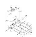
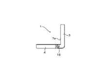
図1Aは、本発明に係るある実施例に即した開いた状態の、セパレーション・ストリップがセットされていない第一セパレーター1aの斜視図である。FIG. 1A is a perspective view of a
第一セパレーター1aは、下部部品4および、下部部品4に対して略垂直な位置に描かれた上部部品3を有している。上部部品3は、その下の領域に、上部部品3に対して垂直に設けられたジョイント突出部を有している。このジョイント突出部と、これらジョイント突出部に挟まれた図1A左に描かれている下部部品4の段状の末端部には、ジョイント・ピン15が差し込まれた穿孔があり、これらにより下部部品4と上部部品3を開閉/折畳むことができるようにするジョイント5が形成されている。The
上部部品3と下部部品4のマテリアルの厚さおよび寸法は、略同じである。図1Aにおいて右側に伸びる下部部品4のエッジは、丸みを帯びており、図1Aにおいて上方に描かれている上部部品3のエッジも同様である。よって、上部部品3と下部部品4の側面は、互いに略揃っている。The material thickness and dimensions of the
図1Aから明らかな如く、上部部品3には、ジョイントの近くに切り込み部8が設けられているため、セパレーター1aが閉じられた状態でも、下部部品4の上面の後方末端には、アクセスできる。As is clear from FIG. 1A, the
下部部品4の上面の上には、下部部品4の上面の前から後ろまで至り、後方と左右には側壁を有し制限され、前方は開放されている凹部6が形成されている。図1Aの後方に描かれている側壁は、血清あるいは血漿を、より簡単に取り出すことができるよう、貫通孔を有していてもよい。On the upper surface of the
凹部6の左右の側壁には、互いに向かい合うノーズ(鼻)状の、凹部6に横から突き出、この部分の幅を狭くしている浮き彫り部9が形成されている。ノーズ状の浮き彫り部9は、図1Aでは、凹部6の前方領域に有り、本発明に係る、後に詳しく説明されるセパレーション・ストリップのリミッター9を形成している。On the left and right side walls of the
上部部品3の、長方形の切り込み部8の真横には、敷居状かつ凹部6に対して垂直方向に第一凸部7aが形成されており、図1Aでは、前方方向に向いているため、第一セパレーター1aが閉じた状態においては、下向きとなる。A first
凹部6の底面上、凹部6の後部には、図1Aでは凹部6からはみ出している第二凸部7bが設けられている。第二凸部7bは、第一セパレーター1aを閉じた状態において、第一凸部7aと互いに作用するように配置されている。第二凸部7bも敷居状であり、凹部6の縦方向に対して垂直方向に向けられている。On the bottom surface of the
図1Aの凸部7aおよび7bは、単なる例であり、その形状は任意、例えば双方の凸部の幅を広くする、或いは、凸部は、折れ曲がる乃至湾曲していてもよい。The
上部部品3には、時間計測ユニット48がはめ込まれており、図1Aでは、デジタル表示とその右側にある二つの操作ボタンから構成されている。時間計測ユニット48により、セパレーション・ストリップが血清あるいは血漿を毛細管現象によって赤血球から分離し、血液取り出し開口側の血液分離部末端に集めるのに必要な時間が経過したかどうかを計測できる。この時間の経過後、セパレーター1aにより、血清あるいは血漿を、セパレーション・ストリップから搾り出すことができる。In the
時間設定は、操作ボタンにより手動で設定できる。例えば、成人の血液検体では、約0.5分、新生児の血液検体では、約1分、また未熟児の血液検体では約2分の時間が必要となる。The time setting can be set manually with an operation button. For example, an adult blood sample requires approximately 0.5 minutes, a neonatal blood sample approximately 1 minute, and a premature infant blood sample approximately 2 minutes.
時間測定は、セパレーション・ストリップに血液を導入した時点から開始される。時間計測ユニット48による時間測定は、時間計測ユニット48の操作ボタンを押すことで開始される。代案として、図1Aには、図示されていないスイッチやセンサーによって、上部部品3と下部部品4を閉じ合わせた時点から開始させることもできる。Time measurement starts from the time when blood is introduced into the separation strip. Time measurement by the
時間経過後、時間計測ユニット48は、音声信号あるいは視覚信号を発し、セパレーション・ストリップを、血清あるいは血漿を搾り出すために引っ張ることができることを知らす。After the time has elapsed, the
時間計測ユニット48の最も簡単な実施形態では、デジタル表示の代わりに、時間経過後に点灯ないし点滅するLED、および/あるいは、時間経過後にビープ音を発生するブザーとしてもよい。In the simplest embodiment of the
時間計測ユニット48は、第一セパレーター1aとのみ図示したが、時間計測ユニット48は、他のセパレーター1b, 1c, 1dや1eにも取り付けることができる。セパレーター1b, 1c, 1dや1eの時間計測ユニット48に関する独立した記載は、重複を避けるため割愛する。Although the
図1Bは、本発明に係るある第二実施例に即した、開いた状態の、セパレーション・ストリップがセットされていない第二セパレーター1bの斜視図である。FIG. 1B is a perspective view of the
第二セパレーター1bの第一セパレーター1aとの違いは、第一凸部7aと第二凸部7bの代わりに半円形の第三凸部27aと半円形の第四凸部27bが取り付けられていることである。第三凸部27aの開部と第四凸部27bの開部は、ジョイント5の方向を向いている。The difference between the
図1Cは、本発明に係るある第三実施例に即した、開いた状態の、セパレーション・ストリップがセットされていない第三セパレーター1cの斜視図である。FIG. 1C is a perspective view of the
第三セパレーター1cの第一セパレーター1aとの違いは、第一凸部7aと第二凸部7bの代わりにV字状の第五凸部37aとV字状の第六凸部37bが取り付けられていることであるが、これらは、二等辺三角形の形状をなし、等しい二辺がつながれ、角となり、その角がジョイント5の反対側を向いている。The difference between the
図1Dは、本発明に係るある第四実施例に即した、開いた状態の、セパレーション・ストリップがセットされていない第四セパレーター1dの斜視図である。FIG. 1D is a perspective view of the
第四セパレーター1dの第一セパレーター1aとの違いは、第一凸部7aと第二凸部7bの代わりにローラー乃至シリンダー47aとローラー乃至シリンダー47bが取り付けられていることである。ローラー47aと47bにより、セパレーション・ストリップを弱い力で、簡単に動かし、ずらすことができる。The difference between the
第一ローラー47aと第二ローラー47bは、上部部品3の下面約半分の位置、および、下部部品4の上面に配置され、特に、セパレーション・ストリップを動かす、乃至、ずらす際に回転するように、上部部品3と下部部品4の凹部6の縦方向、乃至、セパレーション・ストリップの移動方向に対して直角に配置された第一軸7cと第二軸7dに回転自在に取り付けられていることが好ましい。The
代替案として、図1Dには図示されていない、ローラー47aと47bを駆動する少なくとも一つの電動駆動モーターを装備することもできる。この際、動駆動モーターは、第四セパレーター1dの上部部品3乃至下部部品4にはめ込まれることが好ましい。ローラー47aと47bの双方を駆動したいのであれば、共通の駆動モーターを上部部品3乃至下部部品4に取り付ける、乃至、ローラー47a用には、上部部品3に、ローラー47b用には、下部部品4にそれぞれ一つの電動駆動モーターを取り付けることも可能である。As an alternative, at least one electric drive motor for driving the
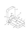
図1Eは、本発明に係るある第五実施例に即した、開いた状態の、セパレーション・ストリップがセットされていない第五セパレーター1eの斜視図である。FIG. 1E is a perspective view of a fifth separator 1e in an opened state without a separation strip, according to a fifth embodiment of the present invention.
第五セパレーター1eの第一セパレーター1aとの違いは、上部部品3の面取りしたエッジと下部部品4の面取りしたエッジに永久磁石22がはめられていることにある。これらは、図1Eの例示では、円形の断面を有しており、第五セパレーター1eを閉じた状態において互いに向かい合うように配置されている。上部部品3の永久磁石22と下部部品4の永久磁石22は、それぞれ反対方向の磁性になっており、引き合うようになっている。そのため、第五セパレーター1eを閉じた状態にすると、上部部品3と下部部品4の間に定義された力がかかり、手動で上部部品3と下部部品4を押さえ合わせる必要がなくなる。The difference between the fifth separator 1e and the
図1Fは、本発明に係るある第六実施例に即した、開いた状態の、セパレーション・ストリップがセットされていない第六セパレーター1fの斜視図である。FIG. 1F is a perspective view of a
第六セパレーター1fの第三セパレーター1cとの違いは、二等辺三角形の形状をなすV字状の凸部38aと38bにおいて、等しい二辺がつながれた角がジョイント5の方向を向いていることにある。The difference between the
図2Aおよび図2Bは、第一実施例に即した本発明に係る第一セパレーション・ストリップ2aを断面図(図2A)および上面図(図2B)として示している。2A and 2B show a
この第一セパレーション・ストリップ2aは、ある血液検体から血清あるいは血漿を分離するためのものである。図2Aの中央部には、ホールド部10に囲まれた血液分離部11が示されている。ホールド部10は、下ホールド部10aと上ホールド部10bから構成され、血液分離部11を覆っている。図2A左に示されている上ホールド部10bの前方領域には、第一血液導入領域12aが設けられており、ここから、血液検体は、血液分離部11に導入される。図2A右に示されている上ホールド部10bの後方領域には、血液取り出し開口13が設けられている。The
図2Bには、この上面図において点線で示される血液分離部11を覆うホールド部10が示されている。第一血液導入領域12aは、図2B左に示される血液分離部11の前末端部に明確に示されている。FIG. 2B shows a
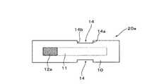
図3は、本発明に係る第二セパレーション・ストリップ20aの上面図である。FIG. 3 is a top view of the
第二セパレーション・ストリップ20aの第一セパレーション・ストリップ2aとの違いは、図2Aと2Bに示す如く、第二セパレーション・ストリップ20aの長辺に、それぞれ後リミッター14aと前リミッター14bを有する、それぞれ長方形の切り取り部14が設けられていることである。これらリミッター14aと14bは、セパレーターにセットされた状態では、ノーズ状の浮き彫り部9にぶつかるため、第二セパレーション・ストリップ20aは、セパレーター内の定義された二箇所の間のみを移動できる。The difference between the
図2と図3において、セパレーション・ストリップ2a乃至20aの第一血液導入領域12aとして表されている領域は、分離フィールドとも呼ぶことができる。セパレーション・ストリップ2aと20aの図2や図3では見えない下面には、通し番号が振られている。2 and 3, the region represented as the first
図4は、第三セパレーション・ストリップ2bの上面図を、図5は、第四セパレーション・ストリップ20bの上面図を示している。4 shows a top view of the
第三セパレーション・ストリップ2bおよび第四セパレーション・ストリップ20bの第一セパレーション・ストリップ2aおよび第二セパレーション・ストリップ20aとの違いは、その後方が半円形になっている血液導入領域12bのみである。The difference between the
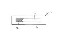
図6は、第五セパレーション・ストリップ2cの上面図を、図7は、第六セパレーション・ストリップ20cの上面図を示している。6 shows a top view of the
第五セパレーション・ストリップ2cおよび第六セパレーション・ストリップ20cの第一セパレーション・ストリップ2aおよび第二セパレーション・ストリップ20aとの違いは、その後方がV字型になっている血液導入領域12cのみである。The
図8は、開いた状態の、第二セパレーション・ストリップ20aがセットされている第一セパレーター1aの斜視図である。FIG. 8 is a perspective view of the
この図では、第二セパレーション・ストリップ20aの上面の第一血液導入領域12aは、明確に示されている。そして、第二セパレーション・ストリップ20aの上面にある血液取り出し開口13は、図8左、第二セパレーション・ストリップ20aの後部末端に点線で示されている。凹部6内にある第二凸部7bは、第二セパレーション・ストリップ20aで隠されているため、図4では見えない。In this figure, the first
図8では、第二セパレーション・ストリップ20aの切り取り部14の前リミッター14bが、ノーズ状の浮き彫り部9と接触しており、第二セパレーション・ストリップ20aは、押し込んだ位置にあることも明確に示されている。FIG. 8 clearly shows that the
図9Aは、第一セパレーター1aの開いた状態の縦断面図である。FIG. 9A is a longitudinal sectional view of the
上の部品は、垂直に立った上部部品3であり、図9Aでは、水平に描かれている下部部品4とジョイント・ピン15により開閉自在につながれている。後方に向いている上部部品3の上面には、製品名やメーカーのロゴなどが貼り付けられる切り欠き部16が設けられている。上部部品3の下面には、前方に向いている第一凸部7aが見える。下部部品4の上面には、凹部の側壁に形成されたノーズ状の浮き彫り部9や凹部6の底面上に形成された第二凸部7bも見える。The upper part is an
図9Bは、第一セパレーター1aの開いた状態の側面図である。FIG. 9B is a side view of the
この図では、水平に描かれている下部部品4と垂直に描かれている上部部品3が見える。これらに加え、上部部品3の下面には、第一凸部7aが見える。In this figure, the
図10は、ジョイント・ピン15の斜視図である。FIG. 10 is a perspective view of the
ジョイント・ピン15は、これにドライバーを差し込みジョイント・ピン15を動かす乃至回転させることのできるスリット20が設けられた額面19を有するヘッド18を備えている。ジョイント・ピン15は更に、ヘッド18よりも細い直径を有し、且つ、ヘッド18とは、切り込み21で間隔がおかれたボルト17も備えている。尚、図10のボルト17は、短縮して描かれている。実際にはボルトは、ヘッド18から見て、下部部品4から反対側の上部部品3のジョイント部を越えるような長さに作られている。The
第二セパレーション・ストリップ20aを用いるセパレーター1a, 1b, 1c, 1d, 1e或いは1fは、以下のように操作される:
約50μlの血液を血液検体として、例えば、ピペットで第一血液導入領域12aに塗布する。この際毛細管現象により血清あるいは血漿は、赤血球から血清あるいは血漿が、血液分離部11の後部末端、血液取り出し開口13付近に集まるように分離される。The
About 50 μl of blood is applied as a blood sample to the first
その後、第二セパレーション・ストリップ20aは、図8に示す如く、第一血液導入領域12aを上に向けた状態で、セパレーター1a, 1b, 1c, 1d, 1e或いは1fに、前リミッター14bが、ノーズ状浮き彫り部9に接触するようにセットされる。即ち、第二セパレーション・ストリップ20aは、差し込まれた状態にある。Thereafter, as shown in FIG. 8, the
分析対象に応じて0.5から2分経過後、上部部品3と下部部品4を合わせ、セパレーターを閉じる。上部部品3と下部部品4を互いに軽く押さえながら第二セパレーション・ストリップ20aを後リミッター14aにノーズ状浮き彫り部9がぶつかるまで、注意深く引っ張る。第五セパレーター1eを用いる場合は、永久磁石22が、上部部品3と下部部品4を磁力により押さえ合せてくれるため、手動で上部部品3と下部部品4を押さえ合わせる必要はない。After 0.5 to 2 minutes depending on the analysis target, the
凸部7aおよび7bの血液分離部11への作用により、血清あるいは血漿は、血液取り出し開口13から搾り出され、第二セパレーション・ストリップ20aの先端から放出される。By the action of the
第二セパレーター1b、第三セパレーター1c或いは第六セパレーター1fを用いる場合、半円形凸部27aと27b、V字型凸部37aと37b或いは38aと38bの作用により、第二セパレーション・ストリップ20aを凹部6から引き出す時に、血清あるいは血漿が、第二セパレーション・ストリップ20aの中央に集まり、第二セパレーション・ストリップ20aの中央から押し出される。When the
第四セパレーター1dを使用する際は、ローラー47aと47bの作用により、第二セパレーション・ストリップ20aを凹部6から引き出す時に、血清あるいは血漿が、第二セパレーション・ストリップ20aから非常に優しく押し出される。When using the
第二セパレーション・ストリップ20aの代わりに、半円形の血液導入領域12bを備えた第四セパレーション・ストリップ20b、或いは、V字型の血液導入領域12cを備えた第六セパレーション・ストリップ20cを用いる場合、血清あるいは血漿を、更に有利にセパレーション・ストリップ12b或いは12cの中央部に集め、中央部から押し出すことが可能になる。Instead of the
血清あるいは血漿は、例えば毛細管などで吸い込み、手で触れることなく採集することができる。最後に、毛細管は、血清あるいは血漿が漏れないように、密封キットにより密封されることが特に好ましい。この毛細管は、このまま測定に具すことができる。Serum or plasma can be collected, for example, by inhalation with a capillary tube and without touching it. Finally, the capillaries are particularly preferably sealed with a sealing kit so that serum or plasma does not leak. This capillary tube can be used for measurement as it is.
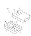
図11は、下部部品52と取り外された状態の上部部品60からなる第六セパレーター50の斜視図である。FIG. 11 is a perspective view of the
下部部品52と上部部品60は共に、同じ厚さの丸みを帯びたエッジを有する略長方形であり、上部部品60の後部末端の中央には、長方形の切り込み部62が設けられている。下部部品52の上面周縁部には、図11では、縦方向の溝として形成されている、長細いガイド・レール58が二本設けられている。下部部品52の上面の上には、下部部品52の上面の前から後ろまで至り、後方と左右には側壁を有し制限され、前方は開放されている縦長の凹部54が形成されている。後方の側壁は、血清あるいは血漿を、より簡単に取り出すことができるよう、貫通孔を有していてもよい。The
凹部54の左右の側壁には、対面に固定用突起56が設けられており、その幅は、セパレーション・ストリップ20a, 20b或いは20cの切り取り部14の幅に対応している。固定用突起56により、凹部54にセットされたセパレーション・ストリップ20a, 20b或いは20cは確実に固定され、一定の位置に保たれる。Fixing
図12は、上部部品60の下から見た斜視図である。FIG. 12 is a perspective view of the
長方形の切り込み部62の直前、上部部品60の後部には、上部部品60の略下面レベルに凹部54の縦方向、乃至、セパレーション・ストリップの移動方向に対して直角に置かれた軸に支えられたローラー64が取り付けられている。よって、ローラー64は、上部部品60の下面レベルよりも、少し下にはみ出しており、ローラー64は、セパレーション・ストリップがずれる際に回転し、血清あるいは血漿を搾り出す圧力をセパレーション・ストリップにかける。Immediately before the
上部部品60の周縁部、凹部62の側方には、二つのスライダー66が、表面から下向きに突出している。スライダー66は、下部部品52のガイド・レール58にはめられ、上部部品60を移動中、ガイド・レール58内でガイドする。スライダー66は、第六セパレーター50の縦方向において、これらがガイド・レール58の後部末端にぶつかり、上部部品60の移動が後方で制限され、ローラー64が血液取り出し開口13から血清あるいは血漿を搾り出すものの、搾り出された血清あるいは血漿が、セパレーション・ストリップ20a, 20b, 20cの後部と接触しないように、ローラー64の後ろに配置されている。
このように、上部部品側のスライダー66と下部部品側のガイド・レール58により、上部部品60を下部部品52に対して摺動自在な、摺動メカニズムが構成されている。Two
As described above, the
尚、図11から13の該摺動メカニズムは、単なる例にすぎず、任意な方法で実施できる。例えば、下部部品52の側面にガイド・レールを設け、上部部品60の幅を下部部品52よりも広くし、下部部品52の側面のガイド・レールに対応するスライダーを取り付けることも可能である。この際、上部部品60は、下部部品52に対して、凹部54が開放され、セパレーション・ストリップ20a, 20b, 20cがセットできる分、後ろにずらすことが可能としてある。図11から13の実施形態の如く、スライダーは、縦方向において、これらが側面のガイド・レールの後部末端にぶつかり、上部部品60の移動が後方で制限され、ローラー64が血液取り出し開口13から血清あるいは血漿を搾り出すものの、搾り出された血清あるいは血漿が、セパレーション・ストリップ20a, 20b, 20cの後部と接触しないように、配置されている。Note that the sliding mechanism shown in FIGS. 11 to 13 is merely an example, and can be implemented by any method. For example, a guide rail may be provided on the side surface of the
図13は、下部部品52と、最大スライド位置に取り付けられた状態の上部部品60からなる第六セパレーター50の斜視図である。FIG. 13 is a perspective view of the
図13では見えないが、スライダー66は、ガイド・レール58の後部末端にぶつかり、上部部品60の後部末端は、下部部品52の末端からはみ出している。
上部部品60の上面前方には、第一セパレーター1aの時間計測ユニット48と同様な、デジタル表示とその右側にある二つの操作ボタンから構成されている時間計測ユニット68がはめ込まれている。
セパレーション・ストリップ20a, 20b, 20cを用いる第六セパレーター50は、以下のように操作される:
先ず、セパレーション・ストリップ20a, 20b, 20cを、血液導入領域12aを上に向けた状態で、固定用突起56が切り取り部14に嵌り、セパレーション・ストリップ20a, 20b, 20cが、下部部品52に固定され、一定の位置に保たれるようにセパレーター50にセットする。約50μlの血液を血液検体として、例えば、ピペットで第一血液導入領域12a, 12b, 12cに塗布すると、セパレーション・ストリップにより、血清あるいは血漿は、毛細管現象によって赤血球から、血液取り出し開口13側の血液分離部末端11に集まるように分離される。上部部品60をずらした状態で下部部品52に、スライダー66がガイド・レール58に嵌るように取り付ける。ボタン操作、或いは、上部部品60を下部部品52に取り付けたことを認識するスイッチやセンサーにより、時間計測ユニット68が起動される。これが、設定された時間の経過後、音声シグナルあるいは視覚的シグナルが発する。続いて上部部品60が、手動、或いは、内蔵されている電動モーターによって、下部部品52に対して、スライダー66がガイド・レール58の末端にぶつかるまで後方に摺動される。この際、ローラー64の血液分離部11への作用により、血清あるいは血漿は、血液取り出し開口13から搾り出され、セパレーション・ストリップ20a, 20b, 20cの先端から放出される。
血清あるいは血漿は、上部部品60の切り込み部62から、例えば、毛細管などで吸い込み、採集することができる。最後に、毛細管は、血清が漏れないように、密封キットにより密封されることが特に好ましい。この毛細管は、このまま測定に具すことができる。Although not visible in FIG. 13, the
Similar to the
The
First, with the separation strips 20a, 20b, and 20c facing the
Serum or plasma can be sucked and collected from the
1a 第一セパレーター
1b 第二セパレーター
1c 第三セパレーター
1d 第四セパレーター
1e 第五セパレーター
1f 第六セパレーター
2a 第一セパレーション・ストリップ
20a 第二セパレーション・ストリップ
2b 第三セパレーション・ストリップ
20b 第四セパレーション・ストリップ
2c 第五セパレーション・ストリップ
20c 第六セパレーション・ストリップ
3 上部部品
4 下部部品
5 ジョイント
6 凹部
7a 第一凸部
7b 第二凸部
7c 第一軸
7d 第二軸
8 切り込み部
9 浮き彫り部
10 ホールド部
11 血液分離部
12a 第一血液導入領域
12b 第二血液導入領域
12c 第三血液導入領域
13 血液取り出し開口
14 切り取り部
14a 後リミッター
14b 前リミッター
15 ジョイント・ピン
16 切り欠き部
17 ボルト
18 ヘッド
19 額面
20 スリット
21 切り込み
22 永久磁石
27a 第三凸部
27b 第四凸部
37a 第五凸部
37b 第六凸部
38a 第七凸部
38b 第八凸部
47a 第一ローラー
47b 第二ローラー
48 時間計測ユニット
50 第七セパレーター
52 下部部品
54 凹部
56 固定用突起
58 ガイド・レール
60 上部部品
62 切り込み部
64 ローラー
66 スライダー
68 時間計測ユニット1a First separator
1b Second separator
1c Third separator
1d 4th separator
1e Fifth separator
1f 6th separator
2a First Separation Strip
20a Second Separation Strip
2b 3rd separation strip
20b 4th separation strip
2c Fifth separation strip
20c 6th separation strip
3 Upper part
4 Lower part
5 Joint
6 Recess
7a 1st convex part
7b Second convex part
7c 1st axis
7d second axis
8 notch
9 Relief
10 Hold section
11 Blood separation part
12a First blood introduction area
12b Second blood introduction area
12c Third blood introduction area
13 Blood extraction opening
14 Cutout
14a after limiter
14b front limiter
15 Joint pin
16 Notch
17 volts
18 heads
19 face value
20 slits
21 notches
22 Permanent magnet
27a Third convex part
27b Fourth convex part
37a Fifth convex part
37b Sixth convex part
38a 7th convex part
38b 8th convex part
47a First roller
47b Second roller
48 hour measurement unit
50 7th separator
52 Lower part
54 recess
56 Fixing protrusion
58 Guide rail
60 Upper part
62 Notch
64 rollers
66 Slider
68 Time measurement unit
Claims (28)
Translated fromJapanese上部部品(3)は、下部部品(4)とジョイントを介して(5)開閉自在に接続されており、
下部部品(4)は、セパレーション・ストリップ(2a-c; 20a-c)をセットできるように構成されており、
下部部品(4)および/あるいは上部部品(3)の下面に少なくとも一つの、上部部品(3)と下部部品(4)を閉じる際に、セパレーション・ストリップ(2a-c; 20a-c)に局所的に圧力をかけるための凸部(7a-b; 27a-b; 37a-b; 38a-b; 47a-b)が形成され、セパレーション・ストリップ(2a-c; 20a-c)を引っ張ることにより、血清あるいは血漿が、セパレーション・ストリップ(2a-c; 20a-c)の後部末端から放出されることを特徴とするセパレーター(1a-f)。A separator equipped with an upper part (3), a lower part (4) and a joint (5) for removing serum or plasma of a blood sample from a separation strip (2a-c; 20a-c),
The upper part (3) is connected to the lower part (4) through a joint (5) so that it can be opened and closed.
The lower part (4) is configured so that a separation strip (2a-c; 20a-c) can be set,
When closing at least one upper part (3) and lower part (4) on the lower surface of the lower part (4) and / or upper part (3), the separation strip (2a-c; 20a-c) By forming a convex strip (7a-b; 27a-b; 37a-b; 38a-b; 47a-b) to apply pressure and pulling the separation strip (2a-c; 20a-c) Separator (1a-f), characterized in that serum or plasma is released from the rear end of the separation strip (2a-c; 20a-c).
下部部品(52)は、セパレーション・ストリップ(2a-c; 20a-c)をセットできるように構成されており、
上部部品(60)の下面に少なくとも一つの、上部部品(60)を下部部品(52)に対して摺動させる際に、セパレーション・ストリップ(2a-c; 20a-c)に局所的に圧力をかけるための凸部(64)が形成され、血清あるいは血漿が、セパレーション・ストリップ(2a-c; 20a-c)の後部末端から放出されることを特徴とするセパレーター(50)。A lower part (52) for removing serum or plasma from a blood sample from the separation strip (2a-c; 20a-c) and an upper part (60) slidable with respect to the lower part (52) An equipped separator,
The lower part (52) is configured to allow the separation strip (2a-c; 20a-c) to be set,
When the upper part (60) slides relative to the lower part (52) with at least one lower surface of the upper part (60), local pressure is applied to the separation strip (2a-c; 20a-c). A separator (50), characterized in that a protrusion (64) for application is formed and serum or plasma is released from the rear end of the separation strip (2a-c; 20a-c).
ことを特徴とする請求項1乃至23のうちいずれか一項に記載のセパレーター(1a-f; 50)。A time measuring unit (48) for measuring a settable time interval and generating a visual or audio signal after the lapse of time is attached to the upper part (3) or the lower part (4). 24. A separator (1a-f; 50) according to any one of claims 1 to 23.
血液分離部(11)、
血液分離部(11)をカバーし固定するホールド部(10)、
ホールド部(10)の血液分離部(11)をカバーする領域の前方末端部に形成される血液導入領域(12a-c)、並びに、
ホールド部(10)の血液分離部(11)をカバーする領域の後方末端部に形成される血液取り出し開口(13)、 から構成されるセパレーション・ストリップ(20a-c)であって、
少なくとも一方の長辺側に、少なくとも一つの前および後リミッター(14a, 14b)を有する狭窄部(14)を備え、セパレーション・ストリップ(20a-c)がリミッター(14a, 14b) により制限された間隔を動けるようになっている、或いは、固定用突起(56)に固定できるようになっていることを特徴とするセパレーション・ストリップ(20a-c)。Blood separator (11) for separating serum or plasma from a blood sample using a separator (1a-f),
A holding part (10) for covering and fixing the blood separation part (11),
A blood introduction region (12a-c) formed at the front end of the region covering the blood separation portion (11) of the hold portion (10), and
A separation strip (20a-c) composed of a blood extraction opening (13) formed at the rear end of the region covering the blood separation part (11) of the holding part (10),
On at least one long side, it is provided with a constriction (14) having at least one front and rear limiter (14a, 14b), and the separation strip (20a-c) is limited by the limiter (14a, 14b). Separation strip (20a-c), characterized in that it can be moved or can be fixed to a fixing projection (56).
Applications Claiming Priority (2)
| Application Number | Priority Date | Filing Date | Title |
|---|---|---|---|
| DE202006007817UDE202006007817U1 (en) | 2006-05-16 | 2006-05-16 | Separator for extracting serum from blood sample in separation strip, comprising hinged upper and lower parts with projections for pressing serum from the strip on folding the parts together |
| PCT/EP2007/004390WO2007131793A1 (en) | 2006-05-16 | 2007-05-16 | Separator and separation strip |
Publications (1)
| Publication Number | Publication Date |
|---|---|
| JP2009537799Atrue JP2009537799A (en) | 2009-10-29 |
Family
ID=36794733
Family Applications (1)
| Application Number | Title | Priority Date | Filing Date |
|---|---|---|---|
| JP2009510353APendingJP2009537799A (en) | 2006-05-16 | 2007-05-16 | Separator and separation strip |
Country Status (7)
| Country | Link |
|---|---|
| US (2) | US8574497B2 (en) |
| EP (2) | EP2163893B1 (en) |
| JP (1) | JP2009537799A (en) |
| AT (1) | ATE453118T1 (en) |
| DE (2) | DE202006007817U1 (en) |
| ES (1) | ES2340964T3 (en) |
| WO (1) | WO2007131793A1 (en) |
Families Citing this family (5)
| Publication number | Priority date | Publication date | Assignee | Title |
|---|---|---|---|---|
| DE202006007817U1 (en) | 2006-05-16 | 2006-07-27 | Pfaff, Dieter | Separator for extracting serum from blood sample in separation strip, comprising hinged upper and lower parts with projections for pressing serum from the strip on folding the parts together |
| US9222931B2 (en) | 2011-06-15 | 2015-12-29 | Tim Pfaff | Plasma or serum separator |
| USD766457S1 (en)* | 2014-08-20 | 2016-09-13 | Neurotar Ltd | Medical instrument, instrument and tool for laboratory use |
| US12332234B2 (en) | 2018-12-07 | 2025-06-17 | Siemens Healthcare Diagnostics Inc. | Solution collection device with evaluation element |
| WO2021015808A1 (en) | 2019-07-19 | 2021-01-28 | Siemens Healthcare Diagnostics Inc. | Tangent flow hemolysis detection blood testing device |
Family Cites Families (12)
| Publication number | Priority date | Publication date | Assignee | Title |
|---|---|---|---|---|
| US4065263A (en)* | 1976-04-02 | 1977-12-27 | Woodbridge Iii Richard G | Analytical test strip apparatus |
| US4288228A (en)* | 1979-01-31 | 1981-09-08 | Technicon Instruments Corporation | Whole blood analyses and diffusion apparatus therefor |
| DE3130749C2 (en) | 1981-08-04 | 1984-06-07 | Boehringer Mannheim Gmbh, 6800 Mannheim | Rapid diagnostic agent and method for its use, in particular for quantitative determinations |
| GB8703081D0 (en) | 1987-02-11 | 1987-03-18 | Sec Dep For Scotland | Sampling service |
| US5114678A (en)* | 1990-03-21 | 1992-05-19 | Miles Inc. | Device for wiping a reagent strip |
| US5258314A (en)* | 1991-03-18 | 1993-11-02 | Paradigm Biotechnologies Partnership | Microprocessor-based biomedical monitoring apparatus and method |
| AU2510692A (en)* | 1991-08-22 | 1993-03-16 | Cascade Medical, Inc. | Disposable reagent unit with blood or fluid guard |
| AUPO071396A0 (en)* | 1996-06-28 | 1996-07-25 | Chandler, Howard Milne | Chromatographic assay or test device |
| US7056475B2 (en)* | 2002-01-30 | 2006-06-06 | Agilent Technologies, Inc. | Fluidically isolated pumping and metered fluid delivery system and methods |
| US7407742B2 (en) | 2002-02-27 | 2008-08-05 | Sanko Junyaku Co., Ltd. | Plasma or serum separator, plasma or serum sampling method, plasma or serum separating method, test carrier and glass fiber |
| US7695676B2 (en)* | 2004-08-11 | 2010-04-13 | Hans Kloepfer | Methods and apparatus for analyzing an analysis fluid |
| DE202006007817U1 (en) | 2006-05-16 | 2006-07-27 | Pfaff, Dieter | Separator for extracting serum from blood sample in separation strip, comprising hinged upper and lower parts with projections for pressing serum from the strip on folding the parts together |
- 2006
- 2006-05-16DEDE202006007817Upatent/DE202006007817U1/ennot_activeExpired - Lifetime
- 2007
- 2007-05-16ESES07725305Tpatent/ES2340964T3/enactiveActive
- 2007-05-16DEDE502007002426Tpatent/DE502007002426D1/enactiveActive
- 2007-05-16EPEP09173187Apatent/EP2163893B1/enactiveActive
- 2007-05-16USUS12/300,913patent/US8574497B2/ennot_activeExpired - Fee Related
- 2007-05-16EPEP07725305Apatent/EP2018555B1/ennot_activeNot-in-force
- 2007-05-16JPJP2009510353Apatent/JP2009537799A/enactivePending
- 2007-05-16ATAT07725305Tpatent/ATE453118T1/enactive
- 2007-05-16WOPCT/EP2007/004390patent/WO2007131793A1/enactiveApplication Filing
- 2012
- 2012-05-09USUS13/467,752patent/US20120241365A1/ennot_activeAbandoned
Also Published As
| Publication number | Publication date |
|---|---|
| US20090321330A1 (en) | 2009-12-31 |
| EP2018555A1 (en) | 2009-01-28 |
| US8574497B2 (en) | 2013-11-05 |
| ES2340964T3 (en) | 2010-06-11 |
| WO2007131793A1 (en) | 2007-11-22 |
| ATE453118T1 (en) | 2010-01-15 |
| US20120241365A1 (en) | 2012-09-27 |
| EP2018555B1 (en) | 2009-12-23 |
| EP2163893B1 (en) | 2013-01-23 |
| DE502007002426D1 (en) | 2010-02-04 |
| DE202006007817U1 (en) | 2006-07-27 |
| EP2163893A1 (en) | 2010-03-17 |
Similar Documents
| Publication | Publication Date | Title |
|---|---|---|
| JP2009537799A (en) | Separator and separation strip | |
| CN100348155C (en) | Piercing assembly, extraction tool for piercing parts and piercing device | |
| US8562814B2 (en) | Measurement device and sensor ejection method | |
| TWI319988B (en) | Analyte detection system | |
| CA2524812C (en) | Analysis system for analysis of a liquid sample on an analytical test element | |
| US20080166269A1 (en) | Device For Analyzing a Liquid Sample | |
| JP5465014B2 (en) | Analytical system and disposable integrated sample acquisition and analysis member for determining analytes in body fluids | |
| CN104144645B (en) | Blood analyser | |
| BRPI0614762A2 (en) | integrated test system for monitoring body fluids | |
| CA2590855A1 (en) | Self-contained test sensor | |
| US8101126B2 (en) | Sensor release mechanism for a meter | |
| EP1696279A3 (en) | Image forming apparatus and developer cartridge | |
| JP2014530052A (en) | Blood sample detection | |
| US20230341380A1 (en) | Lateral Flow Test Kits | |
| CN212059304U (en) | Backlight optical detection device | |
| US4662545A (en) | Disposable capillary tube device | |
| US20050274058A1 (en) | Insect trap with removable glueboard | |
| EP2769215B1 (en) | Metering device for fluid- testing strips | |
| KR20040025496A (en) | Case for adhesive tape | |
| JP7489331B2 (en) | Device and method for collecting plasma | |
| US8545755B2 (en) | Sensor release mechanism for a test meter | |
| CN104135928B (en) | equipment used to draw blood samples | |
| JP2005261960A (en) | Blood analyzer | |
| CN117388481A (en) | Blood monitor with test strip ejector | |
| MX2007015117A (en) | Multi-contact sensor connector with release mechanism. |