JP2009534100A - Surgical fixation method and apparatus - Google Patents
Surgical fixation method and apparatusDownload PDFInfo
- Publication number
- JP2009534100A JP2009534100AJP2009506571AJP2009506571AJP2009534100AJP 2009534100 AJP2009534100 AJP 2009534100AJP 2009506571 AJP2009506571 AJP 2009506571AJP 2009506571 AJP2009506571 AJP 2009506571AJP 2009534100 AJP2009534100 AJP 2009534100A
- Authority
- JP
- Japan
- Prior art keywords
- fixture
- mandrel
- distal end
- hole
- torso
- Prior art date
- Legal status (The legal status is an assumption and is not a legal conclusion. Google has not performed a legal analysis and makes no representation as to the accuracy of the status listed.)
- Granted
Links
Images


Classifications
- A—HUMAN NECESSITIES
- A61—MEDICAL OR VETERINARY SCIENCE; HYGIENE
- A61B—DIAGNOSIS; SURGERY; IDENTIFICATION
- A61B17/00—Surgical instruments, devices or methods
- A61B17/068—Surgical staplers, e.g. containing multiple staples or clamps
- A—HUMAN NECESSITIES
- A61—MEDICAL OR VETERINARY SCIENCE; HYGIENE
- A61B—DIAGNOSIS; SURGERY; IDENTIFICATION
- A61B17/00—Surgical instruments, devices or methods
- A61B17/064—Surgical staples, i.e. penetrating the tissue
- A—HUMAN NECESSITIES
- A61—MEDICAL OR VETERINARY SCIENCE; HYGIENE
- A61L—METHODS OR APPARATUS FOR STERILISING MATERIALS OR OBJECTS IN GENERAL; DISINFECTION, STERILISATION OR DEODORISATION OF AIR; CHEMICAL ASPECTS OF BANDAGES, DRESSINGS, ABSORBENT PADS OR SURGICAL ARTICLES; MATERIALS FOR BANDAGES, DRESSINGS, ABSORBENT PADS OR SURGICAL ARTICLES
- A61L31/00—Materials for other surgical articles, e.g. stents, stent-grafts, shunts, surgical drapes, guide wires, materials for adhesion prevention, occluding devices, surgical gloves, tissue fixation devices
- A61L31/14—Materials characterised by their function or physical properties, e.g. injectable or lubricating compositions, shape-memory materials, surface modified materials
- A61L31/148—Materials at least partially resorbable by the body
- B—PERFORMING OPERATIONS; TRANSPORTING
- B25—HAND TOOLS; PORTABLE POWER-DRIVEN TOOLS; MANIPULATORS
- B25B—TOOLS OR BENCH DEVICES NOT OTHERWISE PROVIDED FOR, FOR FASTENING, CONNECTING, DISENGAGING OR HOLDING
- B25B17/00—Hand-driven gear-operated wrenches or screwdrivers
- B—PERFORMING OPERATIONS; TRANSPORTING
- B25—HAND TOOLS; PORTABLE POWER-DRIVEN TOOLS; MANIPULATORS
- B25B—TOOLS OR BENCH DEVICES NOT OTHERWISE PROVIDED FOR, FOR FASTENING, CONNECTING, DISENGAGING OR HOLDING
- B25B23/00—Details of, or accessories for, spanners, wrenches, screwdrivers
- B25B23/02—Arrangements for handling screws or nuts
- B25B23/04—Arrangements for handling screws or nuts for feeding screws or nuts
- B25B23/06—Arrangements for handling screws or nuts for feeding screws or nuts using built-in magazine
- B25B23/065—Arrangements for handling screws or nuts for feeding screws or nuts using built-in magazine the magazine being coaxial with the tool axis
- A—HUMAN NECESSITIES
- A61—MEDICAL OR VETERINARY SCIENCE; HYGIENE
- A61B—DIAGNOSIS; SURGERY; IDENTIFICATION
- A61B17/00—Surgical instruments, devices or methods
- A61B17/56—Surgical instruments or methods for treatment of bones or joints; Devices specially adapted therefor
- A61B17/58—Surgical instruments or methods for treatment of bones or joints; Devices specially adapted therefor for osteosynthesis, e.g. bone plates, screws or setting implements
- A61B17/68—Internal fixation devices, including fasteners and spinal fixators, even if a part thereof projects from the skin
- A61B17/84—Fasteners therefor or fasteners being internal fixation devices
- A61B17/86—Pins or screws or threaded wires; nuts therefor
- A61B17/8605—Heads, i.e. proximal ends projecting from bone
- A61B17/861—Heads, i.e. proximal ends projecting from bone specially shaped for gripping driver
- A—HUMAN NECESSITIES
- A61—MEDICAL OR VETERINARY SCIENCE; HYGIENE
- A61B—DIAGNOSIS; SURGERY; IDENTIFICATION
- A61B17/00—Surgical instruments, devices or methods
- A61B17/56—Surgical instruments or methods for treatment of bones or joints; Devices specially adapted therefor
- A61B17/58—Surgical instruments or methods for treatment of bones or joints; Devices specially adapted therefor for osteosynthesis, e.g. bone plates, screws or setting implements
- A61B17/68—Internal fixation devices, including fasteners and spinal fixators, even if a part thereof projects from the skin
- A61B17/84—Fasteners therefor or fasteners being internal fixation devices
- A61B17/86—Pins or screws or threaded wires; nuts therefor
- A61B17/864—Pins or screws or threaded wires; nuts therefor hollow, e.g. with socket or cannulated
- A—HUMAN NECESSITIES
- A61—MEDICAL OR VETERINARY SCIENCE; HYGIENE
- A61B—DIAGNOSIS; SURGERY; IDENTIFICATION
- A61B17/00—Surgical instruments, devices or methods
- A61B17/56—Surgical instruments or methods for treatment of bones or joints; Devices specially adapted therefor
- A61B17/58—Surgical instruments or methods for treatment of bones or joints; Devices specially adapted therefor for osteosynthesis, e.g. bone plates, screws or setting implements
- A61B17/88—Osteosynthesis instruments; Methods or means for implanting or extracting internal or external fixation devices
- A61B17/8875—Screwdrivers, spanners or wrenches
- A—HUMAN NECESSITIES
- A61—MEDICAL OR VETERINARY SCIENCE; HYGIENE
- A61B—DIAGNOSIS; SURGERY; IDENTIFICATION
- A61B17/00—Surgical instruments, devices or methods
- A61B17/064—Surgical staples, i.e. penetrating the tissue
- A61B2017/0647—Surgical staples, i.e. penetrating the tissue having one single leg, e.g. tacks
- A61B2017/0648—Surgical staples, i.e. penetrating the tissue having one single leg, e.g. tacks threaded, e.g. tacks with a screw thread
Landscapes
- Health & Medical Sciences (AREA)
- Surgery (AREA)
- Life Sciences & Earth Sciences (AREA)
- Engineering & Computer Science (AREA)
- Animal Behavior & Ethology (AREA)
- General Health & Medical Sciences (AREA)
- Veterinary Medicine (AREA)
- Heart & Thoracic Surgery (AREA)
- Public Health (AREA)
- Mechanical Engineering (AREA)
- Nuclear Medicine, Radiotherapy & Molecular Imaging (AREA)
- Biomedical Technology (AREA)
- Medical Informatics (AREA)
- Molecular Biology (AREA)
- Vascular Medicine (AREA)
- Epidemiology (AREA)
- Surgical Instruments (AREA)
- Prostheses (AREA)
Abstract
Translated fromJapaneseDescription
Translated fromJapanese本発明は、外科用固定方法及び装置に関する。 The present invention relates to a surgical fixation method and apparatus.
外科用固定具は、多くの異なる医療処置に広く使用されている。例えば、組織、人工器官、又は他の材料の2つ以上の部分を相互に固定するために、ステープル、縫合糸、クリップ及び他の固定具が、腹腔鏡処置及び開放外科処置に一般的に使用されている。固定具は、骨と非吸収性人工器官の間のような2つの部分の間に永久的な接続を提供するか、又はメッシュ人工器官と筋肉又は他の組織との間のような一時的な固定を提供して、組織の内植又は他の癒着プロセスを可能にし、組織に対してメッシュをより確実に固定することができる。 Surgical fasteners are widely used in many different medical procedures. For example, staples, sutures, clips, and other fasteners are commonly used in laparoscopic and open surgical procedures to secure two or more portions of tissue, prosthesis, or other material to each other. Has been. The fixture provides a permanent connection between two parts, such as between a bone and a non-absorbable prosthesis, or a temporary, such as between a mesh prosthesis and a muscle or other tissue. Fixation can be provided to allow tissue ingrowth or other adhesion processes to more securely fix the mesh to the tissue.
例えば、Jervisの米国特許公開第2004/0049227号は、人工器官を組織に取り付ける、例えば、ヘルニア修復処置でメッシュ人工器官を取り付ける螺旋状固定具及びアプリケータを開示している。Jervisに開示されたアプリケータは、回転体を使用して螺旋状の線コイル形状を有する1つ又は複数の固定具を展開して、固定具を回転させ、アプリケータの遠位端から放出することができる。1つの実施形態では、コイル固定具の内部分に設置された静止安定器が、固定具と係合するねじ形状を有し、固定具が回転されると、それを遠位方向に送り出す。 For example, US Patent Publication No. 2004/0049227 to Jervis discloses a helical fixture and applicator for attaching a prosthesis to tissue, eg, attaching a mesh prosthesis in a hernia repair procedure. The applicator disclosed in Jervis uses a rotating body to deploy one or more fasteners having a helical wire coil shape to rotate the fixture and release it from the distal end of the applicator. be able to. In one embodiment, a stationary ballast located on the inner portion of the coil fixture has a threaded shape that engages the fixture and delivers it distally as the fixture is rotated.
とりわけ、ヘルニア修復などの外科的処置でメッシュを固定するために使用される他の固定具が、Kayanの米国特許公開第2004/0204723号及びCriscuoloの米国特許公開第2005/0171562号に開示されている。Kayan及びCriscuoloでは両方とも、固定具はスクリュー状構造にねじ山形態及び頭部を含む。また、これらの固定具は、吸収性材料で作成されていると言われている。それ故、固定具は、外科処置が終了した後に分解して身体に吸収することができる。 Other fasteners used, among other things, to secure meshes in surgical procedures such as hernia repairs are disclosed in Kayan US Patent Publication No. 2004/0204723 and Crisculo US Patent Publication No. 2005/0171562. Yes. In both Kayan and Crisculo, the fixture includes a thread form and a head in a screw-like structure. These fixtures are also said to be made of absorbent material. Therefore, the fastener can be disassembled and absorbed by the body after the surgical procedure is completed.
本発明の1つの態様では、外科用固定具は胴部分を含み、その螺旋ねじ山が胴部分の遠位端付近から胴部分の近位端に向かって延びている。頭部分は胴部分の近位端に設置することができ、貫通孔は頭部分及び胴部分を通って延びることができる。貫通孔はねじ部分を含み、胴部分及び頭部分は生体吸収性材料で形成することができる。1つの実施形態では、貫通孔は、貫通孔の近位端に設置されたねじなし部分を有することができる。ねじ部分は、貫通孔の遠位端に設置され、ねじなし部分は貫通孔の長さの約半分にわたって延びることができる。固定具の頭部分は、ドライバと係合して胴部分を回転させ、組織内に入れるように適合された少なくとも1つの駆動機構を含むことができる。例えば、少なくとも1つの駆動機構は、頭部分の側の対向平坦部分を含むことができる。 In one aspect of the invention, the surgical fastener includes a torso portion with a helical thread extending from near the distal end of the torso portion toward the proximal end of the torso portion. The head portion can be located at the proximal end of the torso portion, and the through hole can extend through the head portion and the torso portion. The through hole includes a screw portion, and the trunk portion and the head portion can be formed of a bioabsorbable material. In one embodiment, the through hole can have an unthreaded portion located at the proximal end of the through hole. The threaded portion is located at the distal end of the through hole, and the unthreaded portion can extend over about half the length of the through hole. The head portion of the fixture can include at least one drive mechanism adapted to engage the driver and rotate the torso portion into the tissue. For example, the at least one drive mechanism can include opposing flat portions on the side of the head portion.
本発明の別の態様では、外科用固定具は、縦軸を有する胴部分、及び胴部分の遠位端付近から胴部分の近位端に向かって延びる螺旋ねじ山を含む。胴部分の遠位端は少なくとも一部が、縦軸を横断する面に配置される。頭部分は、胴部分の近位端に取り付けられ、胴部分の最大幅より大きい最大幅を有することができる。貫通孔は、縦軸に沿って頭部分及び胴部分を通って延びることができ、胴部分及び頭部分は生体吸収性材料で形成することができる。1つの実施形態では、胴部分の遠位端は、縦軸に対して傾斜した面を有することができる。 In another aspect of the invention, the surgical fastener includes a torso portion having a longitudinal axis and a helical thread extending from near the distal end of the torso portion toward the proximal end of the torso portion. At least a portion of the distal end of the barrel portion is disposed in a plane transverse to the longitudinal axis. The head portion is attached to the proximal end of the torso portion and may have a maximum width that is greater than the maximum width of the torso portion. The through-hole can extend along the longitudinal axis through the head portion and the torso portion, and the torso portion and the head portion can be formed of a bioabsorbable material. In one embodiment, the distal end of the barrel portion can have a surface that is inclined with respect to the longitudinal axis.
本発明の別の態様では、外科用固定具は縦軸を有する胴部分、及び胴部分の遠位端付近から胴部分の近位端に向かって延びる螺旋ねじ山を含むことができる。頭部分は胴部分の近位端に取り付けられ、半径方向に胴部分の最大幅より大きい最大幅を有することができる。頭部分の対向側は、回転体と係合して、展開中に縦軸の周囲で固定具を回転させるように適合された湾曲凹部を有することができる。貫通孔は、縦軸に沿って頭部分及び胴部分を通って延び、胴部分及び頭部分は生体吸収性材料で形成することができる。 In another aspect of the invention, the surgical fastener can include a torso portion having a longitudinal axis and a helical thread extending from near the distal end of the torso portion toward the proximal end of the torso portion. The head portion is attached to the proximal end of the torso portion and may have a maximum width radially greater than the maximum width of the torso portion. The opposite side of the head portion can have a curved recess adapted to engage the rotating body and rotate the fixture about the longitudinal axis during deployment. The through hole extends along the longitudinal axis through the head portion and the torso portion, and the torso portion and the head portion can be formed of a bioabsorbable material.
本発明の別の態様では、外科用固定具システムは、雄ねじ山を有する胴部分、及び胴部分を通って延び、雌ねじ山部分を有する貫通孔をそれぞれが有する複数の固定具を含むことができる。ねじ部分を有するマンドレルが、複数の固定具の貫通孔のねじ部分と係合するように適合されてもよく、回転体が、少なくとも1つの固定具をマンドレルに沿って動かすように、複数の固定具のうち少なくとも1つと係合して、それを回転させるように適合されてもよい。固定具がマンドレルに沿って移動すると、固定具が展開して組織又は他の材料に入ることができる。1つの実施形態では、マンドレルは遠位先端を有することができ、マンドレルは回転体の遠位端を越えて遠位先端を延ばせるように動作可能であってもよい。システムは、内部に回転体及びマンドレルの少なくとも一部が設置された外管を含むことができる。複数の固定具それぞれの雌ねじ部分を、貫通孔の遠位部分に設置することができ、貫通孔の近位部分はねじ山がなくてもよい。システムは、マンドレル及び回転体の近位端にハンドルを含むことができ、ハンドルは、回転体を動作させるように配置された少なくとも1つのトリガを含むことができる。 In another aspect of the invention, a surgical fastener system can include a barrel portion having an external thread and a plurality of fasteners each having a through hole extending through the barrel portion and having an internal thread portion. . A mandrel having a threaded portion may be adapted to engage the threaded portion of the through holes of the plurality of fixtures, and the plurality of fixtures such that the rotating body moves the at least one fixture along the mandrels. It may be adapted to engage and rotate at least one of the tools. As the fixture moves along the mandrel, the fixture can deploy and enter tissue or other material. In one embodiment, the mandrel may have a distal tip and the mandrel may be operable to extend the distal tip beyond the distal end of the rotating body. The system may include an outer tube in which at least a part of the rotating body and the mandrel is installed. The female thread portion of each of the plurality of fasteners can be placed at the distal portion of the through hole, and the proximal portion of the through hole may be unthreaded. The system can include a handle at the proximal end of the mandrel and rotating body, and the handle can include at least one trigger arranged to operate the rotating body.
本発明の別の態様では、固定具を展開する方法は、ねじ付きマンドレルに装着された複数の固定具を提供するステップを含み、各固定具は、雄ねじを有する胴部分と、胴部分を通って延び、雌ねじ部分を有する貫通孔とを有する。固定具の少なくとも1つは、マンドレルに対して回転して、マンドレルの遠位端から少なくとも1つの固定具を展開することができる。1つの実施形態では、ねじ付きマンドレルに装着された固定具を管内に収容し、マンドレルの遠位端を管の遠位端の外側に延ばすことができる。管は、管と係合する固定具を回転させるように回転することができる。マンドレルの遠位端は鋭利であってもよく、マンドレルの鋭利な遠位端は材料内に延びることができる。少なくとも1つの固定具は、遠位端が材料内に延びた後、マンドレルの遠位端から展開することができる。 In another aspect of the invention, a method of deploying a fixture includes providing a plurality of fixtures attached to a threaded mandrel, each fixture having a barrel portion having an external thread and a trunk portion passing through the barrel portion. And a through hole having a female screw portion. At least one of the fixtures can be rotated relative to the mandrel to deploy at least one fixture from the distal end of the mandrel. In one embodiment, a fixture attached to a threaded mandrel can be housed within the tube and the distal end of the mandrel can extend outside the distal end of the tube. The tube can be rotated to rotate a fixture that engages the tube. The distal end of the mandrel may be sharp and the sharp distal end of the mandrel can extend into the material. At least one fastener can be deployed from the distal end of the mandrel after the distal end extends into the material.
本発明の上記及び他の態様は、以下の説明及び特許請求の範囲から明らかになるだろう。 These and other aspects of the invention will be apparent from the following description and claims.
本発明の態様を、例示的実施形態について以下で説明する。ここで、類似の番号は類似の要素を示す。 Aspects of the invention are described below with respect to exemplary embodiments. Here, similar numbers indicate similar elements.
本明細書では図を参照しながら本発明の態様を説明し、それらの図は本発明の態様による例示的実施形態を示すことを理解されたい。本明細書で説明する例示的実施形態は、必ずしも本発明のすべての態様を示すものではなく、それどころか幾つかの例示的実施形態を説明するために使用されている。それ故、本発明の態様は、例示的実施形態に鑑みて狭義に解釈されないものとする。更に、本発明の態様は、単独で、又は本発明の他の態様と任意の適切な組合せで使用できることを理解されたい。 It should be understood that aspects of the invention are described herein with reference to the drawings, which illustrate exemplary embodiments according to aspects of the invention. The exemplary embodiments described herein do not necessarily represent all aspects of the invention, but rather are used to describe some exemplary embodiments. Therefore, aspects of the invention are not to be construed in a narrow sense in view of the exemplary embodiments. Furthermore, it should be understood that aspects of the invention can be used alone or in any suitable combination with other aspects of the invention.
本発明の1つの態様では、固定具適用システムは、雄ねじを有する胴部分、及び胴部分を通って、例えば、胴の縦軸に沿って延びる貫通孔をそれぞれが含む複数の固定具を含むことができる。固定具は、それぞれ胴部分及び/又は胴の雄ねじより広くてもよい頭部分を含むことができる。固定具は、マンドレルに沿って配置することができ、マンドレルは、ねじ部分を有し、固定具の貫通孔を通って延びる。各固定具の貫通孔の少なくとも一部は、マンドレルのねじ部分と係合する雌ねじ部分を有することができる。固定具上を延びる管などの回転体が固定具と係合してこれを回転し、これにより固定具をマンドレルに沿って動作させることができる。すなわち、マンドレルは静止したままで、回転する固定具が、固定具の雌ねじ部分とマンドレルのねじ部分との係合によってマンドレルに沿って前進することができる。 In one aspect of the invention, a fixture application system includes a barrel portion having external threads and a plurality of fixtures each including a through hole extending through the barrel portion, for example, along the longitudinal axis of the barrel. Can do. The fixture may include a torso portion and / or a head portion that may be wider than the torso male thread, respectively. The fixture can be disposed along the mandrel, the mandrel has a threaded portion and extends through the through hole of the fixture. At least a portion of the through hole of each fixture may have an internal thread portion that engages the thread portion of the mandrel. A rotating body such as a tube extending over the fixture engages and rotates the fixture, thereby allowing the fixture to operate along the mandrel. That is, the mandrel remains stationary and the rotating fixture can be advanced along the mandrel by engagement of the internal thread portion of the fixture and the thread portion of the mandrel.
固定具システムは、例えば、ヘルニア修復処置でメッシュを筋肉組織に固定するために、固定具を対象組織又は他の材料内に展開するために使用することができる。固定具を展開するために、マンドレルの前端又は遠位端を、最初に対象材料の隣に設置することができる。1つの例示的実施形態では、マンドレルを対象材料内に挿入することができ、例えば、マンドレルの尖った端部を対象材料内に挿入することができる。回転体は、固定具をマンドレルに沿って遠位方向に前進させ、対象材料内に入れるように、少なくともマンドレルの遠位端の最も近くに設置された固定具を回転することができる。マンドレル上の他の固定具も、最も遠位側の固定具が展開されるにつれて、固定具をマンドレルの遠位端に向かって送り出すように回転することができる。最も遠位側の固定具が回転すると、固定具の胴の雄ねじが対象材料(例えば、メッシュ、組織及び/又はその他)と係合し、固定具を材料内に引き込むことができる。固定具に設けた頭部は、固定具を材料面に据え付け、2つ以上の材料を一緒に保持し、及び/又は材料への固定具の過剰挿入を防止することを助けることができる。 The fixture system can be used to deploy the fixture into the target tissue or other material, for example, to fix the mesh to muscle tissue in a hernia repair procedure. To deploy the fixture, the front or distal end of the mandrel can first be placed next to the material of interest. In one exemplary embodiment, the mandrel can be inserted into the target material, for example, the sharp end of the mandrel can be inserted into the target material. The rotator can rotate at least the fixture located closest to the distal end of the mandrel to advance the fixture distally along the mandrel and into the material of interest. Other fasteners on the mandrel can also be rotated to deliver the fixture toward the distal end of the mandrel as the most distal fixture is deployed. As the distal-most fastener rotates, the male thread on the fastener barrel engages the target material (eg, mesh, tissue and / or others) and the fastener can be drawn into the material. The head provided on the fixture can help to fix the fixture on the material surface, hold two or more materials together, and / or prevent over-insertion of the fixture into the material.
図1は、例示的実施形態の固定具アプライヤ100及び関連する固定具を示す。アプライヤ100は、ハンドル1と、ハンドル1から遠位方向に延びるシャフト2とを含む。シャフト2は、回転体3及びマンドレル5上の複数の固定具4を収容する。ハンドル1上のトリガ又は他のアクチュエータ6を使用者が操作することができ、これにより回転体3が少なくとも最も遠位側の固定具4をマンドレル5に対して回転させ、固定具4の雌ねじをマンドレル5のねじと係合させて、固定具4をマンドレル5に対して遠位方向に駆動することができる。アクチュエータ6の操作は、マンドレル5を回転体3及び/又はシャフト2に対して遠位方向に移動させる働きをし、従って例えば、マンドレル5の尖った端部がシャフト2の遠位端から露出する。最も遠位側の固定具4が展開すると、マンドレル5がシャフト2内に後退することができる。 FIG. 1 shows an exemplary
回転体3は、固定具4をマンドレル5に対して回転させるための任意の適切な形態をとることができる。この実施形態では、回転体3は、図2に見られるように、ほぼ楕円形の断面の管状形状を有する。回転体3の平坦面31が、固定具4の対応する面、例えば、固定具4の頭部の平坦な側面と係合することができ、それでも固定具4が回転体3に対してマンドレル5に沿って軸方向に移動することができる。回転体3の円形部分は、例えば、回転中に回転体3がシャフト2内でぐらつくのを防止するのに役立つように、シャフト2の内面と密接に接触することができる。しかし、回転体3は任意の適切な配置構成を有することができることを理解されたい。例えば、回転体3は、固定具4の対応する面と係合するように、六角形、四角形、星形又は他の断面を有することができる。追加的又は代替的に、回転体3は、固定具4と係合して、これを回転させる1つ又は複数のリブ、スプライン、タブ、溝又は他の構造を有することができる。他の実施形態では、回転体3は管状構造を有する必要がなく、他の方法で固定具と係合することができる。例えば、回転体3は、シャフト2を通り、固定具4の対応する穴又は溝を通って長手方向に延びる1つ又は複数の爪を有することができる。爪がマンドレル5の周囲で回転すると、展開するために固定具4が回転することができる。別の配置構成では、回転体3は、シャフト2の一方側に沿って延びる歯車を含むことができる。歯車は、シャフト2の内面内に部分的に延びて、固定具4と接触することができる。歯車が回転すると、固定具(この歯車と係合するために頭部に形成された相補型歯車の歯を有することができる)が回転して、上述したように固定具が展開する。他の配置構成では、回転体3は最も遠位側の固定具4のみを回転させることができ、追従する固定具をばねなどの他の手段で前方に送り出すことができる。例えば、マンドレル5は、シャフトの遠位端付近にねじ部分を含むだけでよい。マンドレル5のこれより近位側の部分は、滑らかな円筒形面又は固定具4と係合しない他の配置構成を有することができる。 The
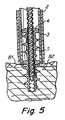
図3〜図5は、図1のアプライヤ100によって展開している固定具を示す。図3では、使用者は、シャフト2の遠位端を対象材料、例えば、筋肉組織82に設置されたメッシュ人工器官81に当てて設置することができる。この時点で、マンドレル5及び最も遠位側の固定具4はシャフト2内に位置することができる(しかし他の実施形態では、マンドレル及び/又は固定具4は露出することができる)。アプライヤ100を起動すると、最初にマンドレル5がシャフト2の遠位端の外側に延び、従ってマンドレル5がメッシュ81及び/又は組織28に突入する。この実施形態では、マンドレル5は対象材料の穿孔を助けるために尖鋭化した先端を有するが、マンドレルの遠位端にねじ錐形状、円錐形先端、尖っていない端部などがあるように、他の配置構成も可能である。別の方法としては、マンドレル5は対象材料に突入せず、例えば、マンドレル5がシャフト2から遠位方向に延びない実施形態では、材料に押しつけるだけか、又は材料の隣に設置することができる。この実施形態でも、マンドレル5は回転せずに対象材料内に延びるが、幾つかの実施形態では、マンドレル5は、例えば、材料に入るのに役立つように、対象材料を穿孔しながら回転することができる。マンドレル5が遠位方向に延びている間、回転体3は静止状態であってもよく、従ってマンドレル5が延びるにつれ、マンドレル5のねじと係合している固定具4が、マンドレル5とともに回転体3に対して遠位方向に摺動する。(例えば、マンドレル5を遠位方向に動かすことに加えて、又はそれに代わってシャフト2の遠位端を材料に押しつける場合などのシャフト2及び/又は回転体3の遠位端を近位方向に後退させることによって、シャフト2の遠位端からマンドレル5を露出することができることを理解されたい。) 3-5 show the fixture deployed by the
マンドレル5が図4に示すように材料内に延びた状態で、回転体3をマンドレル5の周囲で回転することができる。これによって固定具4がマンドレル5(回転方向に静止したままである)に対して回転し、マンドレルのねじ上で遠位方向に動作する。最も遠位側の固定具4の遠位先端がシャフト2から現れると、固定具4はメッシュ81及び組織82に突入する。固定具4とマンドレル5とのねじ係合によって、固定具4が回転体3の回転につれて遠位方向に動作するのに加えて、固定具4の雄ねじがメッシュ81及び組織82と係合して、固定具を材料内に引き込むのに役立つことができる。固定具4が適切に回転すると、固定具4が図5に示すように材料へと十分に挿入される。この実施形態では、固定具4の貫通孔の近位部分がマンドレル5のねじ部分と係合せず、例えば、貫通孔の遠位部分にのみ雌ねじがあり、近位部分は滑らかな円筒形状、又はマンドレルのねじと係合しない他の構成を有する。その結果、固定具4はマンドレル5から係合解除され、マンドレル5、回転体3及びシャフト2をタックから引き出し、固定具4をアプライヤ100から展開することができる。マンドレル5は、シャフト2内の図3に示す位置へと後退し、アプライヤ100内の次の固定具を展開する準備を整えることができる。 With the
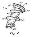
アプライヤ100とともに使用する固定具4は、当業者なら理解することができるように、任意の適切な配置構成を有することができる。図6から図10は、例示的実施形態で固定具4の様々な図を示す。図6は固定具4の側面図を示し、これは頭部41、外螺旋ねじ42及び胴部分43を有する。頭部41は任意の適切な形状及び/又はサイズを有することができ、この実施形態ではねじ42付近の全体的に平坦な遠位面、及び丸まった近位面を有する。雄ねじ42は、図6に示した図の頭部41のサイズに近い直径dを有することができる。雄ねじ42は、胴部分43の周囲で約3.5回転することができるが、他の実施形態では、ねじ42はこれより少なく、又は多く回転することができる。雄ねじ42は、胴部分43の遠位端付近で先細になっていてもよい。この先細りは、固定具がメッシュ81などの対象材料へ突入するのに役立つ。この実施形態では、ねじ42は胴部分43の近位端にて先細にならず、ねじ42が頭部41と接合する点まで比較的一定の直径を維持する。他の実施形態では、ねじ42は、頭部41で、又はその前で先細になり、例えば、ゼロの山頂高さを有することができる。ねじ42が頭部41まで延びると、単に固定具4を反対方向に回転させることにより、固定具4をメッシュ81などの材料から外すのに役立つことができる。他方で、このようなねじの配置構成により、固定具4を「過剰駆動」し、メッシュ81又は他の材料を望ましくない深さまで通過させることができる。ねじ42の最も近位側の端部と頭部41の間にギャップがあると、固定具の挿入を材料面で停止させるのに役立ち、メッシュ81などの幾つかの材料をねじ42と頭部41の間に捕捉させることもできる。雄ねじ42の他の変形版を作成することができる。例えば、様々なねじピッチ、可変ねじピッチ、様々なねじ面角度(前面及び/又は後面)、ねじ山頂の形状(尖る、図示のように平坦、丸まるなど)、2つ以上のねじなどである。また、雄ねじ42は、胴部分43の前方に延びるねじ42の最も遠位側の部分も有することができ、これは例えば、固定具4を材料内に案内するのに役立つねじ錐、フック又は爪部分を形成する。要するに、本発明の幾つかの態様では、任意の適切な雄ねじ42の配置構成を使用することができる。 The
本発明の1つの態様では、胴部分は傾斜した前面431又は楕円形の前縁を有することができる。例えば、図6に示すように、胴部分43は傾斜した遠位端を有することができる。胴部分43が円筒形又は円錐形状を有する場合、傾斜した遠位端の結果、胴部分43には楕円形の前縁が存在する。この配置構成は、固定具4が材料に突入するのに役立つことができる。何故なら、例えば、胴部分43の遠位端の先端部分のみが最初に材料に突入し、遠位端の後続部分を案内するからである。タックの遠位端の他の配置構成が可能であり、それは胴部分43の遠位端が「V」字形のノッチを有する「魚口」タイプの構成を含む。別の方法としては、胴部分43の遠位端は、材料への突入に役立つ鋭利な前縁を有することができる。 In one aspect of the present invention, the barrel portion can have an inclined
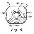
図7及び図8は、固定具4の底面及び上面斜視図を示す。この実施形態では、固定具4の頭部41は、回転体3の平坦面31と係合する対向平坦側面411を含む。また、ねじ42は平坦部分421を含み、これは回転体3の面31と接触して、例えば、回転体3内で固定具4を安定させるのに役立つことができる。平坦部分421は、例えば、固定具4が回転体3内に嵌合することができるように、ねじ42の直径dを頭部41の側面411間の距離より小さくなるように維持しながら、ねじ42の山頂高さを最大にするのにも役立つことができる。また、頭部41は、頭部41の対向側部に湾曲凹部412を含むこともできる。これらの湾曲凹部412は、システム100に装填するために固定具4を組み付ける場合に、複数の固定具4を適切に位置合わせするのを助けることができる。凹部412は、同じサイズ及び/又は形状を有するか、又は異なって、システムに装填された固定具4が全て確実に同様に位置合わせされるのに役立つことができる。固定具4の位置合わせは、例えば、固定具4が非対称形状を有する、例えば、図6に示したように傾斜した遠位面を含む場合に重要になる場合がある。凹部412は、固定具4と回転体3との接触面積を減少させる働きをし、それにより回転体3内の固定具4の摺動運動に抵抗する摩擦を潜在的に減少させることもできる。図9は、湾曲凹部412及び側面411とともに固定具4の上面図を示す。 7 and 8 show a bottom view and a top perspective view of the
本発明の別の態様では、固定具は、胴部分43及び頭部41を通って延びる貫通孔44を有することができる。貫通孔44は、胴部分43の縦軸に沿って延び、図9に見られるように、固定具4を通る通路を提供することができる。本発明の1つの態様では、貫通孔44の一部が、例えば、図10の固定具の断面図で示すような貫通孔44の遠位部分などに雌ねじ部分441を有することができる。貫通孔の近位部分442は、ねじ部分441より大きい直径を有することができ、従って例えば、近位部分442はマンドレル5と係合しない。近位部分442は任意の形状又はサイズを有することができ、例えば、滑らかな円筒形状の孔を有することができる。固定具4の遠位部分のみがマンドレル5と係合するように貫通孔44を配置することにより、展開中に固定具4をさらに容易にマンドレル5から係合解除することができる。しかし、貫通孔44は、全長にわたってねじを切るか、又は近位端にのみねじを切ることが可能である。この場合、マンドレル5は、必要に応じて、遠位端にねじを切らなくてもよい。雌ねじ部分441のピッチは、雄ねじ42のピッチと同じか、又はこれより長いか、又はこれより短くてもよい。この例示的実施形態では、例えば、展開中にマンドレル5からの固定具4の係合解除を助けるのに役立つように、雌ねじ部分441のねじピッチは雄ねじ42のねじピッチより短い。すなわち、雄ねじ42のねじピッチが長くなると、固定具4を材料内に押し込む場合に、固定具4をマンドレル5から引き出すのに役立つ。 In another aspect of the invention, the fixture can have a through-
固定具は、吸収性材料(例えば、PLAなど)、非吸収性金属又はプラスチック(例えば、チタン)、又は任意の他の材料又は材料の組合せなどの任意の適切な生体適合性材料で作成することができる。さらに、固定具4は、例えば、長さ約1/4インチ(約6.35mm)及び直径約1/8インチ(約3.175mm)で、貫通内径の直径が約1/32インチ(約0.794mm)などの任意の適切なサイズで作成することができる。 The fixture is made of any suitable biocompatible material, such as an absorbent material (eg, PLA), a non-absorbable metal or plastic (eg, titanium), or any other material or combination of materials. Can do. Further, the
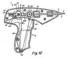
アプライヤ100は、手動操作の機構、電動式機構、又は手動と電動の組合せを使用して、固定具4を展開することができる。図11及び図12は、図1のアプライヤ100の手動操作機構のそれぞれ左側面図及び右側面図を示す。この例示的実施形態では、ハンドル1は両方ともトリガピボット63の周囲で旋回する2つの操作可能なトリガレバー61及び62を有するトリガ6を含む。外部トリガレバー61は露出し、使用者によって把持され、内部トリガレバー62は外部トリガレバー61内に収容される。トリガレバー61及び62は両方とも、ばね64又は他の適切な弾性部材によって図11に示す始動位置へと押しやられる。外部トリガレバー61は、マンドレル駆動ピニオン11と係合する歯を有するマンドレル駆動ラック611を含む。従って、外部トリガレバー61がハンドル1に向かって動作すると、マンドレル駆動ラック611によってマンドレル駆動ピニオン11が(図11に示すように反時計回りに)回転する。これで、ピニオン11に固定されたマンドレル駆動カム111が回転し、マンドレルスライダ12上のピン121と係合する。外部トリガレバー61が始動位置にある場合は、マンドレル駆動カム111のノッチ112がピン121と係合し、これによってマンドレルスライダ12がばね13の付勢によって近位方向に(図11の右側に)動作することができる。しかし、外部トリガレバー61が押下されて、マンドレル駆動カム111が回転すると、カム111がピン121を遠位方向に押し、これによってマンドレルスライダ12がばね13の付勢に抗して遠位方向に動作する。マンドレルスライダ12はマンドレル5に結合されているので、マンドレル5がマンドレルスライダ12とともに遠位方向に動作する。マンドレルスライダ12は、ノッチ112がピン121から外れるまで、遠位方向に動作するだけである。その後、マンドレルスライダ12及びマンドレル5は静止したままである。 The
外部トリガレバー61が始動位置から初期動作中に、内部トリガレバー62は静止したままである。しかし、外部トリガレバー61がさらに押下されると、外部トリガレバー61が内部トリガレバー62と接触し、従って内部トリガレバー62もトリガピボット63の周囲で回転する。内部トリガレバー62は、回転体駆動ピニオン14(図12参照)と係合する回転体駆動ラック622を含む。従って、内部トリガレバー62が動作すると、回転体駆動ピニオン14及び連動かさ歯車141が回転し、これはクラッチ15の相補型かさ歯車と係合している。その結果、回転体駆動ピニオン14が回転すると、かさ歯車141がクラッチ15を(例えば、ハンドル1からシャフト2を見下ろして時計回り方向に)回転させる。クラッチ15は、回転体3と係合し、それ故、クラッチ15が時計回り方向に回転すると、回転体3も時計回りに回転する。トリガレバー61及び62を押下し続けると、回転体3が回転し、これによって上述したように固定具4が展開される。爪16がマンドレル駆動ラック611と係合するように配置され、従って固定具の回転が開始すると(すなわち、外部トリガ61が内部トリガ62と接触し、クラッチ15が回転体3を回転させると)、トリガレバー61及び62が完全に押下されるまで、トリガレバー61及び62は図11の始動位置に復帰することができない。トリガレバー61及び62が完全に押下されると、爪16がマンドレル駆動ラック611から外れ、それによってマンドレル駆動ラック611及びトリガレバー61及び62が始動位置へと復帰することができる。トリガレバー61及び62の復帰動作によって、マンドレル駆動ピニオン11及び回転体駆動ピニオン14が後方に押しやられる。その結果、ノッチ112がピン121との係合に復帰し、従ってマンドレルスライド12及びマンドレル5が、ばね13により近位方向に動作することができる。トリガが復帰する間に、かさ歯車141は逆に回転することができるが、クラッチ15が回転体3の回転を防止することができる。代わりに、回転体3はトリガの復帰中に静止したままである。 During the initial operation of the
最も遠位側の固定具4の展開は、トリガレバー61及び62のストローク中に、すなわちトリガレバー61及び62が完全に押下され、爪16がマンドレル駆動ラック611から外れる前に実行することができる。この配置構成は、回転体3の回転が停止して、マンドレル5が後退する前に、固定具4をマンドレル5から確実に係合解除させるのに役立つことができる。例えば、固定具4は、回転体3が3回転するとマンドレル5から係合解除するように配置することができる。しかし、回転体3は、停止する前に3.5回転するように配置することができる。回転体3が回転を停止した後、爪16がラック611から外れるには、トリガレバー61及び62をさらに押下する必要があるように、爪16を配置することができる。トリガレバー61及び62のこの動作中に、カウンタを起動して固定具が展開されたことを表示するなど、他の機能を実行することができる。1つの実施形態では、展開した固定具及び/又は残っている固定具の表示を、例えば、LCD又はLED表示などでハンドル1に提供することができる。 Deployment of the most
本発明の少なくとも1つの実施形態の幾つかの態様について説明してきたが、種々の変更、修正及び改良点が当業者であれば想起されることを理解されたい。このような変更、修正及び改良点は、本開示の一部とされ、本発明の精神及び範囲に入るものとする。従って、上記説明及び図面は例示としてのものにすぎない。 While several aspects of at least one embodiment of the present invention have been described, it should be understood that various changes, modifications and improvements will occur to those skilled in the art. Such alterations, modifications, and improvements are intended to be part of this disclosure, and are intended to be within the spirit and scope of the invention. Accordingly, the foregoing description and drawings are illustrative only.
Claims (42)
Translated fromJapanese自身の遠位端付近から自身の近位端に向かって延びる螺旋ねじを含む胴部分と、
前記胴部分の前記近位端にある頭部分と、
前記頭部分及び前記胴部分を通って延び、ねじ部分を含む貫通孔と、
を備え、
前記胴部分及び頭部分が、生体吸収性材料で形成される固定具。A surgical fixture,
A barrel portion including a helical screw extending from near its distal end toward its proximal end;
A head portion at the proximal end of the torso portion;
A through hole extending through the head portion and the body portion and including a threaded portion;
With
A fixing device in which the trunk portion and the head portion are formed of a bioabsorbable material.
縦軸を有し、自身の遠位端付近から自身の近位端に向かって延びる螺旋ねじを含み、自身の前記遠位端の少なくとも一部が前記縦軸に対して横方向の面に配置される胴部分と、
前記胴部分の前記近位端に取り付けられ、前記胴部分の最大幅より大きい最大幅を有する頭部分と、
前記縦軸に沿って前記頭部分及び前記胴部分を通って延びる貫通孔と、
を備え、
前記胴部分及び前記頭部分が、生体吸収性材料で形成される外科用固定具。A surgical fixture,
A helical screw having a longitudinal axis and extending from near its distal end toward its proximal end, wherein at least a portion of its distal end is disposed in a plane transverse to said longitudinal axis The torso part being
A head portion attached to the proximal end of the torso portion and having a maximum width greater than the maximum width of the torso portion;
A through hole extending through the head portion and the torso portion along the longitudinal axis;
With
A surgical fixture in which the torso portion and the head portion are formed of a bioabsorbable material.
縦軸を有し、自身の遠位端付近から自身の近位端に向かって延びる螺旋ねじを含む胴部分と、
前記胴部分の前記近位端に取り付けられ、半径方向に前記胴部分の最大幅より大きい最大幅を有し、自身の対向側部が、回転体と係合して、展開中に前記固定具を前記縦軸の周囲で回転させるように適合された湾曲凹部を有する頭部分と、
前記縦軸に沿って前記頭部分及び前記胴部分を通って延びる貫通孔と、
を備え、
前記胴部分及び頭部分が、生体吸収性材料で形成される固定具。A surgical fixture,
A barrel portion having a longitudinal axis and including a helical screw extending from near its distal end toward its proximal end;
Affixed to the proximal end of the barrel portion and having a maximum width in a radial direction that is greater than the maximum width of the barrel portion, with its opposite side engaging a rotating body and the fixture during deployment A head portion having a curved recess adapted to rotate about the longitudinal axis;
A through hole extending through the head portion and the torso portion along the longitudinal axis;
With
A fixing device in which the trunk portion and the head portion are formed of a bioabsorbable material.
それぞれが、雄ねじを有する胴部分、及び前記胴部分を通って延び、雌ねじ部分を有する貫通孔を有する複数の固定具と、
前記複数の固定具の前記貫通孔の前記ねじ部分と係合するように適合されたねじ部分を有するマンドレルと、
前記複数の固定具の少なくとも1つと係合して、それを回転して、前記少なくとも1つの固定具を前記マンドレルに沿って動作させるように適合された回転体と、
を含むシステム。A surgical fastener system comprising:
A plurality of fasteners each having a barrel portion having an external thread and a through hole extending through the barrel portion and having an internal thread portion;
A mandrel having a threaded portion adapted to engage the threaded portion of the through-hole of the plurality of fasteners;
A rotating body adapted to engage and rotate at least one of the plurality of fixtures to operate the at least one fixture along the mandrel;
Including system.
ねじ付きマンドレルに装着された複数の固定具を提供するステップであって、前記固定具がそれぞれ、雄ねじを有する胴部分、及び前記胴部分を通って延び、雌ねじ部分を有する貫通孔を有するステップと、
前記マンドレルに対して前記固定具の少なくとも1つを回転して、前記少なくとも1つの固定具を前記マンドレルの遠位端から展開するステップと、
を含む方法。A method of deploying a fixture,
Providing a plurality of fasteners attached to a threaded mandrel, each of the fasteners having a barrel portion having an external thread and a through hole extending through the barrel portion and having an internal thread portion; ,
Rotating at least one of the fixtures relative to the mandrel to deploy the at least one fixture from a distal end of the mandrel;
Including methods.
前記マンドレルの前記遠位端を前記管の遠位端の外側に延ばすステップとをさらに含む、請求項36に記載の方法。The fixture mounted on the threaded mandrel is housed in a tube, the method comprising:
37. The method of claim 36, further comprising extending the distal end of the mandrel outside the distal end of the tube.
前記マンドレルの前記鋭利な遠位端を材料内に延ばすステップをさらに含む、請求項37に記載の方法。The distal end of the mandrel is sharp and the method comprises:
38. The method of claim 37, further comprising extending the sharp distal end of the mandrel into material.
Applications Claiming Priority (3)
| Application Number | Priority Date | Filing Date | Title |
|---|---|---|---|
| US11/408,399 | 2006-04-21 | ||
| US11/408,399US7862573B2 (en) | 2006-04-21 | 2006-04-21 | Method and apparatus for surgical fastening |
| PCT/US2007/009542WO2007123978A2 (en) | 2006-04-21 | 2007-04-18 | Apparatus for surgical fastening |
Related Child Applications (1)
| Application Number | Title | Priority Date | Filing Date |
|---|---|---|---|
| JP2012228950ADivisionJP5627658B2 (en) | 2006-04-21 | 2012-10-16 | Surgical fixation method and apparatus |
Publications (2)
| Publication Number | Publication Date |
|---|---|
| JP2009534100Atrue JP2009534100A (en) | 2009-09-24 |
| JP5268887B2 JP5268887B2 (en) | 2013-08-21 |
Family
ID=38548098
Family Applications (2)
| Application Number | Title | Priority Date | Filing Date |
|---|---|---|---|
| JP2009506571AActiveJP5268887B2 (en) | 2006-04-21 | 2007-04-18 | Surgical fixation |
| JP2012228950AActiveJP5627658B2 (en) | 2006-04-21 | 2012-10-16 | Surgical fixation method and apparatus |
Family Applications After (1)
| Application Number | Title | Priority Date | Filing Date |
|---|---|---|---|
| JP2012228950AActiveJP5627658B2 (en) | 2006-04-21 | 2012-10-16 | Surgical fixation method and apparatus |
Country Status (9)
| Country | Link |
|---|---|
| US (2) | US7862573B2 (en) |
| EP (3) | EP2258279B1 (en) |
| JP (2) | JP5268887B2 (en) |
| AT (1) | ATE486528T1 (en) |
| AU (1) | AU2007240814B2 (en) |
| CA (2) | CA2650018C (en) |
| DE (1) | DE602007010273D1 (en) |
| ES (3) | ES2702984T3 (en) |
| WO (1) | WO2007123978A2 (en) |
Cited By (4)
| Publication number | Priority date | Publication date | Assignee | Title |
|---|---|---|---|---|
| JP2013517885A (en)* | 2010-01-26 | 2013-05-20 | ノヴォラップ メディカル リミテッド | Articulated medical equipment |
| JP2015518753A (en)* | 2012-05-31 | 2015-07-06 | ヴィーア サージカル リミテッド | Variable depth surgical fixation |
| JP2016510648A (en)* | 2013-03-14 | 2016-04-11 | シー・アール・バード・インコーポレーテッドC R Bard Incorporated | Fastener handling inside surgical instruments |
| US10980625B2 (en) | 2012-05-31 | 2021-04-20 | Via Surgical Ltd | Variable depth surgical fixation |
Families Citing this family (117)
| Publication number | Priority date | Publication date | Assignee | Title |
|---|---|---|---|---|
| ES2279156T3 (en) | 2002-06-11 | 2007-08-16 | Tyco Healthcare Group Lp | MALE TIGHTS FOR HERNIAS. |
| US7670362B2 (en) | 2003-06-13 | 2010-03-02 | Tyco Healthcare Group Lp | Multiple member interconnect for surgical instrument and absorbable screw fastener |
| US7960935B2 (en) | 2003-07-08 | 2011-06-14 | The Board Of Regents Of The University Of Nebraska | Robotic devices with agent delivery components and related methods |
| US10478179B2 (en) | 2004-04-27 | 2019-11-19 | Covidien Lp | Absorbable fastener for hernia mesh fixation |
| CN101044286A (en)* | 2004-07-26 | 2007-09-26 | 环球工程固件有限公司 | Attachment of components to composite materials |
| US8100946B2 (en) | 2005-11-21 | 2012-01-24 | Synthes Usa, Llc | Polyaxial bone anchors with increased angulation |
| US9579088B2 (en) | 2007-02-20 | 2017-02-28 | Board Of Regents Of The University Of Nebraska | Methods, systems, and devices for surgical visualization and device manipulation |
| US8679096B2 (en) | 2007-06-21 | 2014-03-25 | Board Of Regents Of The University Of Nebraska | Multifunctional operational component for robotic devices |
| WO2007149559A2 (en) | 2006-06-22 | 2007-12-27 | Board Of Regents Of The University Of Nebraska | Magnetically coupleable robotic devices and related methods |
| WO2008010948A2 (en)* | 2006-07-18 | 2008-01-24 | Davol Inc. | Method and apparatus for surgical fastening |
| JP4702216B2 (en)* | 2006-08-03 | 2011-06-15 | オムロンヘルスケア株式会社 | Electronic blood pressure monitor and control method thereof |
| US8343171B2 (en) | 2007-07-12 | 2013-01-01 | Board Of Regents Of The University Of Nebraska | Methods and systems of actuation in robotic devices |
| US9439681B2 (en) | 2007-07-20 | 2016-09-13 | DePuy Synthes Products, Inc. | Polyaxial bone fixation element |
| PL2170192T3 (en) | 2007-07-20 | 2011-07-29 | Synthes Gmbh | Polyaxial bone fixation element |
| JP2010536435A (en) | 2007-08-15 | 2010-12-02 | ボード オブ リージェンツ オブ ザ ユニバーシティ オブ ネブラスカ | Medical inflation, attachment and delivery devices and associated methods |
| CA2695619C (en) | 2007-08-15 | 2015-11-24 | Board Of Regents Of The University Of Nebraska | Modular and cooperative medical devices and related systems and methods |
| US8597336B2 (en)* | 2007-12-28 | 2013-12-03 | Howmedica Osteonics Corp. | Apparatus for discrete tissue anchoring for soft tissue repair and method of use |
| US8257407B2 (en)* | 2008-04-23 | 2012-09-04 | Aryan Henry E | Bone plate system and method |
| EP2355725B1 (en) | 2008-09-05 | 2017-03-08 | Synthes GmbH | Bone fixation assembly |
| US8777990B2 (en) | 2008-09-08 | 2014-07-15 | Howmedica Osteonics Corp. | Knotless suture anchor for soft tissue repair and method of use |
| JP5815407B2 (en) | 2008-09-12 | 2015-11-17 | ジンテス ゲゼルシャフト ミット ベシュレンクテル ハフツング | Spinal stabilization and guided fixation system |
| KR20110081208A (en) | 2008-09-29 | 2011-07-13 | 신세스 게엠바하 | Multi-Axis Bottom-Loading Screw and Rod Assemblies |
| CA2742399A1 (en) | 2008-11-03 | 2010-06-03 | Dustin M. Harvey | Uni-planar bone fixation assembly |
| US9451942B2 (en)* | 2008-11-12 | 2016-09-27 | Howmedica Osteonics Corp. | Insertion tool for knotless suture anchor for soft tissue repair and method of use |
| US8771315B2 (en)* | 2008-12-15 | 2014-07-08 | Smith & Nephew, Inc. | Composite anchor |
| FR2941144B1 (en)* | 2009-01-22 | 2012-04-27 | Sofradim Production | SURGICAL STAPLER FOR PREPOSITIONING AND ATTACHING TEXTILE PROSTHESIS, METHOD OF LOADING THE SAME, AND SELF-AGRIPPTING SURGICAL STRAIN |
| KR20120013312A (en) | 2009-04-15 | 2012-02-14 | 신세스 게엠바하 | Orthodontic Connectors for Spinal Structures |
| CA2764841A1 (en) | 2009-06-17 | 2010-12-23 | Synthes Usa, Llc | Revision connector for spinal constructs |
| WO2011075693A1 (en) | 2009-12-17 | 2011-06-23 | Board Of Regents Of The University Of Nebraska | Modular and cooperative medical devices and related systems and methods |
| AU2015202455B2 (en)* | 2009-12-30 | 2017-10-19 | Boston Scientific Scimed, Inc. | Implantable sling systems and methods |
| US9345473B2 (en) | 2009-12-30 | 2016-05-24 | Astora Women's Health, Llc | Implantable sling systems and methods |
| US8683895B2 (en)* | 2010-02-23 | 2014-04-01 | Kensey Nash Corporation | Single revolution snap action drive for surgical fasteners |
| EP2600758A1 (en)* | 2010-08-06 | 2013-06-12 | Board of Regents of the University of Nebraska | Methods and systems for handling or delivering materials for natural orifice surgery |
| JP5989759B2 (en)* | 2011-03-22 | 2016-09-07 | スミス アンド ネフュー インコーポレーテッド | Mooring system and feeding device for use with the mooring system |
| JP6174017B2 (en) | 2011-06-10 | 2017-08-02 | ボード オブ リージェンツ オブ ザ ユニバーシティ オブ ネブラスカ | In vivo vascular seal end effector and in vivo robotic device |
| FR2977471B1 (en)* | 2011-07-07 | 2013-07-05 | Aspide Medical | DEVICE COMPRISING A PLURALITY OF IMPLANTS FOR FIXING PROTHETIC EQUIPMENT |
| WO2013009887A1 (en) | 2011-07-11 | 2013-01-17 | Board Of Regents Of The University Of Nebraska | Robotic surgical devices, systems and related methods |
| US9610109B2 (en)* | 2011-08-16 | 2017-04-04 | Howmedica Osteonics Corp. | Wedge shaped fracture fixation devices and methods for using the same |
| CA2849887A1 (en) | 2011-09-26 | 2013-04-04 | Artack Medical (2013) Ltd. | Surgical fastening device and method |
| WO2013052137A2 (en) | 2011-10-03 | 2013-04-11 | Board Of Regents Of The University Of Nebraska | Robotic surgical devices, systems and related methods |
| US8535339B2 (en) | 2011-12-18 | 2013-09-17 | Via Surgical Ltd. | Apparatus and method for suturing |
| WO2013106569A2 (en) | 2012-01-10 | 2013-07-18 | Board Of Regents Of The University Of Nebraska | Methods, systems, and devices for surgical access and insertion |
| EP2844181B1 (en) | 2012-05-01 | 2021-03-10 | Board of Regents of the University of Nebraska | Single site robotic device and related systems |
| EP3189948B1 (en) | 2012-06-22 | 2018-10-17 | Board of Regents of the University of Nebraska | Local control robotic surgical devices |
| US9770305B2 (en) | 2012-08-08 | 2017-09-26 | Board Of Regents Of The University Of Nebraska | Robotic surgical devices, systems, and related methods |
| US12295680B2 (en) | 2012-08-08 | 2025-05-13 | Board Of Regents Of The University Of Nebraska | Robotic surgical devices, systems and related methods |
| EP2882331A4 (en) | 2012-08-08 | 2016-03-23 | Univ Nebraska | ROBOTIC SURGICAL SYSTEMS AND DEVICES, AND ASSOCIATED METHODS |
| US9198657B2 (en) | 2012-09-13 | 2015-12-01 | Basil Anthony Kocur | Anchor unit implant |
| US9351733B2 (en) | 2013-01-18 | 2016-05-31 | Covidien Lp | Surgical fastener applier |
| CN105188562B (en) | 2013-03-06 | 2019-02-26 | 史密夫和内修有限公司 | Micro Anchor |
| US9993245B2 (en) | 2013-03-11 | 2018-06-12 | Via Surgical Ltd. | Surgical tacker with quantity indicator |
| US9358010B2 (en) | 2013-03-12 | 2016-06-07 | Covidien Lp | Flex cable and spring-loaded tube for tacking device |
| US9867620B2 (en) | 2013-03-14 | 2018-01-16 | Covidien Lp | Articulation joint for apparatus for endoscopic procedures |
| CA2906672C (en) | 2013-03-14 | 2022-03-15 | Board Of Regents Of The University Of Nebraska | Methods, systems, and devices relating to force control surgical systems |
| US9427230B2 (en)* | 2013-03-14 | 2016-08-30 | C.R. Bard, Inc. | Handling of fasteners within a surgical instrument |
| CA2905948C (en) | 2013-03-14 | 2022-01-11 | Board Of Regents Of The University Of Nebraska | Methods, systems, and devices relating to robotic surgical devices, end effectors, and controllers |
| CA2906772C (en) | 2013-03-15 | 2021-09-21 | Board Of Regents Of The University Of Nebraska | Robotic surgical devices, systems and related methods |
| US9655621B2 (en) | 2013-03-15 | 2017-05-23 | Covidien Lp | Surgical instrument for dispensing tacks and solution |
| US10085746B2 (en) | 2013-06-28 | 2018-10-02 | Covidien Lp | Surgical instrument including rotating end effector and rotation-limiting structure |
| US9668730B2 (en) | 2013-06-28 | 2017-06-06 | Covidien Lp | Articulating apparatus for endoscopic procedures with timing system |
| US9351728B2 (en) | 2013-06-28 | 2016-05-31 | Covidien Lp | Articulating apparatus for endoscopic procedures |
| US9358004B2 (en) | 2013-06-28 | 2016-06-07 | Covidien Lp | Articulating apparatus for endoscopic procedures |
| US10966700B2 (en) | 2013-07-17 | 2021-04-06 | Virtual Incision Corporation | Robotic surgical devices, systems and related methods |
| US20150032130A1 (en) | 2013-07-24 | 2015-01-29 | Covidien Lp | Expanding absorbable tack |
| US9526498B2 (en) | 2013-09-17 | 2016-12-27 | Covidien Lp | Surgical device with a trigger lockout mechanism device |
| US9615830B2 (en) | 2013-11-08 | 2017-04-11 | C.R. Bard, Inc. | Surgical fastener |
| US9675353B2 (en)* | 2013-11-08 | 2017-06-13 | C.R. Bard, Inc. | Surgical fasteners and associated deployment devices |
| US10285697B2 (en) | 2013-11-08 | 2019-05-14 | C.R. Bard, Inc. | Methods and apparatus for surgical fastening |
| US10368870B2 (en) | 2013-11-08 | 2019-08-06 | C.R. Bard, Inc. | Surgical fastener |
| US9445814B2 (en) | 2013-11-08 | 2016-09-20 | C.R. Bard, Inc. | Surgical fastener |
| CN106102613B (en)* | 2014-02-06 | 2019-07-19 | 英格奈特概念有限公司 | Bone screw assembly |
| US20150272584A1 (en)* | 2014-03-31 | 2015-10-01 | Coloplast A/S | Adapter attachable to a shaft of an anchor delivery tool |
| US10335146B2 (en) | 2014-04-02 | 2019-07-02 | Coviden Lp | Surgical fastener applying apparatus, kits and methods for endoscopic procedures |
| CA2961213A1 (en) | 2014-09-12 | 2016-03-17 | Board Of Regents Of The University Of Nebraska | Quick-release end effectors and related systems and methods |
| EP3217890B1 (en) | 2014-11-11 | 2020-04-08 | Board of Regents of the University of Nebraska | Robotic device with compact joint design |
| US10478238B2 (en) | 2014-12-02 | 2019-11-19 | Activortho, Inc. | Active compression devices, methods of assembly and methods of use |
| US11090097B2 (en) | 2015-03-17 | 2021-08-17 | Covidien Lp | Connecting end effectors to surgical devices |
| ES2821006T3 (en) | 2015-04-23 | 2021-04-23 | Via Surgical Ltd | Surgical Fastener Locking and Delivery Mechanism |
| WO2017024081A1 (en) | 2015-08-03 | 2017-02-09 | Board Of Regents Of The University Of Nebraska | Robotic surgical devices systems and related methods |
| US10363039B2 (en) | 2015-11-20 | 2019-07-30 | Covidien Lp | Surgical fastener appliers |
| US10702264B2 (en) | 2016-01-25 | 2020-07-07 | TransEasy Medical Tech.Co., Ltd | Fixing device for soft tissue |
| CN105496482B (en)* | 2016-01-25 | 2018-06-15 | 北京天助畅运医疗技术股份有限公司 | Absorbable plate and the soft tissue fixation devices containing Absorbable plate |
| CA3015902A1 (en) | 2016-02-26 | 2017-08-31 | Activortho, Inc. | Active compression apparatus, methods of assembly and methods of use |
| US11224467B2 (en) | 2016-02-26 | 2022-01-18 | Activortho, Inc. | Active compression apparatus, methods of assembly and methods of use |
| WO2017184964A1 (en) | 2016-04-21 | 2017-10-26 | Applied Medical Resources Corporation | Laparoscopic clip applier |
| CA3024623A1 (en) | 2016-05-18 | 2017-11-23 | Virtual Incision Corporation | Robotic surgical devices, systems and related methods |
| CA3034671A1 (en) | 2016-08-25 | 2018-03-01 | Shane Farritor | Quick-release tool coupler and related systems and methods |
| WO2018045036A1 (en) | 2016-08-30 | 2018-03-08 | Board Of Regents Of The University Of Nebraska | Robotic device with compact joint design and an additional degree of freedom and related systems and methods |
| US10743859B2 (en) | 2016-10-21 | 2020-08-18 | Covidien Lp | Surgical end effectors |
| US10617409B2 (en) | 2016-10-21 | 2020-04-14 | Covidien Lp | Surgical end effectors |
| US11298123B2 (en) | 2016-10-21 | 2022-04-12 | Covidien Lp | Surgical end effectors |
| CN115337111B (en) | 2016-11-22 | 2025-04-25 | 内布拉斯加大学董事会 | Improved coarse positioning device and related system and method |
| CN115553922A (en) | 2016-11-29 | 2023-01-03 | 虚拟切割有限公司 | User controller with user presence detection and related systems and methods |
| WO2018112199A1 (en) | 2016-12-14 | 2018-06-21 | Virtual Incision Corporation | Releasable attachment device for coupling to medical devices and related systems and methods |
| US10888309B2 (en) | 2017-01-31 | 2021-01-12 | Covidien Lp | Surgical fastener devices with geometric tubes |
| CN117017492A (en) | 2017-09-27 | 2023-11-10 | 虚拟切割有限公司 | Robotic surgical device with tracking camera technology and related systems and methods |
| CA3087672A1 (en) | 2018-01-05 | 2019-07-11 | Board Of Regents Of The University Of Nebraska | Single-arm robotic device with compact joint design and related systems and methods |
| US10932776B2 (en)* | 2018-01-10 | 2021-03-02 | C.R. Bard, Inc. | Surgical fasteners for articulating surgical instruments |
| US11298126B2 (en) | 2018-05-02 | 2022-04-12 | Covidien Lp | Shipping wedge for end effector installation onto surgical devices |
| US11116500B2 (en) | 2018-06-28 | 2021-09-14 | Covidien Lp | Surgical fastener applying device, kits and methods for endoscopic procedures |
| US11648000B2 (en) | 2018-07-30 | 2023-05-16 | Braunvest Llc | Vertebral probes and related surgical methods |
| US12232781B2 (en) | 2018-07-30 | 2025-02-25 | BraunVest, LLC | Cortical/cancellous bone probes and related surgical methods |
| WO2020146348A1 (en) | 2019-01-07 | 2020-07-16 | Virtual Incision Corporation | Robotically assisted surgical system and related devices and methods |
| US11154337B2 (en) | 2019-02-26 | 2021-10-26 | Medos Iniernational Sarl | Spinal screw handling |
| US11246636B2 (en) | 2019-04-26 | 2022-02-15 | Braunvest Llc | Systems, methods, and apparatus for spinal deformity correction |
| US12419670B2 (en)* | 2019-04-26 | 2025-09-23 | BraunVest, LLC | Methods for bone compression and/or fixation |
| US12329429B2 (en)* | 2019-04-26 | 2025-06-17 | Braunvest Llc | Systems, methods, and apparatus for spinal deformity correction |
| US11523817B2 (en) | 2019-06-27 | 2022-12-13 | Covidien Lp | Endoluminal pursestring device |
| US20220354646A1 (en)* | 2019-08-02 | 2022-11-10 | Boston Scientific Scimed, Inc. | Anchor designs configured for anchor migration/backout control |
| CN110916735B (en)* | 2019-11-26 | 2021-09-03 | 杭州电子科技大学 | Degradable bioactive screw and manufacturing method thereof |
| USD944985S1 (en) | 2019-12-19 | 2022-03-01 | Covidien Lp | Positioning guide cuff |
| US11197675B2 (en) | 2019-12-19 | 2021-12-14 | Covidien Lp | Positioning guide for surgical instruments and surgical instrument systems |
| USD944984S1 (en) | 2019-12-19 | 2022-03-01 | Covidien Lp | Tubular positioning guide |
| JP2023532977A (en) | 2020-07-06 | 2023-08-01 | バーチャル インシジョン コーポレイション | Surgical robotic positioning system and related apparatus and methods |
| EP4251083A1 (en)* | 2020-11-30 | 2023-10-04 | Intuitive Surgical Operations, Inc. | Systems for retracting and adjusting elongate flexible devices and associated methods |
| CN113017733A (en)* | 2021-03-30 | 2021-06-25 | 苏州奥芮济医疗科技有限公司 | Medical anchor and processing technology thereof |
| US20240398408A1 (en)* | 2023-06-05 | 2024-12-05 | Cannuflow, Inc. | Staple and driver for tendon stapling apparatus |
Citations (5)
| Publication number | Priority date | Publication date | Assignee | Title |
|---|---|---|---|---|
| JPH0852156A (en)* | 1994-08-15 | 1996-02-27 | Asahi Optical Co Ltd | Bone treatment screw body |
| US5695497A (en)* | 1994-03-29 | 1997-12-09 | Stahelin; Andreas C. | Screw made of biodegradable material for bone surgery purposes, and screwdriver suitable therefor |
| US6517564B1 (en)* | 1999-02-02 | 2003-02-11 | Arthrex, Inc. | Bioabsorbable tissue tack with oval-shaped head and method of tissue fixation using same |
| US20050171562A1 (en)* | 2002-06-11 | 2005-08-04 | Criscuolo Christopher J. | Hernia mesh tacks |
| EP1698295A1 (en)* | 2005-03-01 | 2006-09-06 | Linvatec Corporation | Bone screw and driver system |
Family Cites Families (94)
| Publication number | Priority date | Publication date | Assignee | Title |
|---|---|---|---|---|
| US1815594A (en) | 1929-10-01 | 1931-07-21 | Keller Mechanical Eng | Screw driver screw holding device |
| US2033039A (en) | 1935-05-22 | 1936-03-03 | Arthur A Limpert | Double point rotary pin |
| US3258042A (en)* | 1964-08-24 | 1966-06-28 | Herbert C Brauchla | Screw strip driving gun |
| US3545444A (en) | 1967-10-02 | 1970-12-08 | United States Surgical Corp | Wire suture wrapping instrument |
| US3579793A (en) | 1968-09-24 | 1971-05-25 | Microdot Inc | Power tool for thread inserts |
| US3515194A (en) | 1969-03-17 | 1970-06-02 | Acme Staple Co Inc | Threaded staple |
| US3737579A (en) | 1971-04-19 | 1973-06-05 | Medtronic Inc | Body tissue electrode and device for screwing the electrode into body tissue |
| US3971421A (en) | 1974-02-26 | 1976-07-27 | Triad Fastener Corporation | Air-powered, self-feeding screw driving tool |
| US4154241A (en)* | 1977-07-29 | 1979-05-15 | Rudie Peter S | Anastomosis clamp |
| US4146321A (en)* | 1977-08-08 | 1979-03-27 | Melillo Dominic S | Reversible film cartridge and camera |
| US4809695A (en) | 1981-10-21 | 1989-03-07 | Owen M. Gwathmey | Suturing assembly and method |
| US4496090A (en) | 1982-03-10 | 1985-01-29 | Crevier Paul H | Surgical stapler |
| US4449283A (en) | 1982-06-16 | 1984-05-22 | Microdot Inc. | Semi-automatic insert tool |
| DE3327751A1 (en)* | 1982-08-06 | 1984-02-09 | Avdel Ltd., Welwyn Garden City, Hertfordshire | ANCHOR NUT FASTENER |
| US4595007A (en) | 1983-03-14 | 1986-06-17 | Ethicon, Inc. | Split ring type tissue fastener |
| US4595009A (en)* | 1984-02-06 | 1986-06-17 | Medtronic, Inc. | Protection circuit for implantable cardioverter |
| US4873976A (en) | 1984-02-28 | 1989-10-17 | Schreiber Saul N | Surgical fasteners and method |
| US4667545A (en) | 1985-06-03 | 1987-05-26 | Gould Jr Frederick H | Screw gun automatic feed |
| GB8514608D0 (en)* | 1985-06-10 | 1985-07-10 | Crosfield Electronics Ltd | Colour modification in image reproduction systems |
| JPS628193A (en)* | 1985-07-04 | 1987-01-16 | インタ−ナショナル ビジネス マシ−ンズ コ−ポレ−ション | Color image display system |
| EP0209685A3 (en)* | 1985-07-12 | 1988-11-09 | Fischerwerke Arthur Fischer GmbH & Co. KG | Fixation element for osteosynthesis |
| US4662555A (en) | 1986-03-11 | 1987-05-05 | Edward Weck & Company, Inc. | Surgical stapler |
| US4884572A (en) | 1986-05-20 | 1989-12-05 | Concept, Inc. | Tack and applicator for treating torn bodily material in vivo |
| US4878794A (en)* | 1988-03-15 | 1989-11-07 | John W. Hall, Jr. | Collated screw fasteners |
| DE3811345C1 (en) | 1988-04-02 | 1989-09-07 | Aesculap Ag, 7200 Tuttlingen, De | |
| CA1320005C (en)* | 1988-06-16 | 1993-07-06 | Kotaro Harigane | Electronic component mounting apparatus |
| CH681273A5 (en) | 1988-12-16 | 1993-02-26 | Sulzer Ag | |
| US5053047A (en) | 1989-05-16 | 1991-10-01 | Inbae Yoon | Suture devices particularly useful in endoscopic surgery and methods of suturing |
| US5129906A (en)* | 1989-09-08 | 1992-07-14 | Linvatec Corporation | Bioabsorbable tack for joining bodily tissue and in vivo method and apparatus for deploying same |
| US5035692A (en) | 1990-02-13 | 1991-07-30 | Nicholas Herbert | Hemostasis clip applicator |
| US5161725A (en) | 1990-02-13 | 1992-11-10 | Ethicon, Inc. | Rotating head skin stapler |
| US5127413A (en) | 1990-08-09 | 1992-07-07 | Ebert Edward A | Sinous suture |
| US5098238A (en)* | 1990-12-20 | 1992-03-24 | Hi-Shear Corporation | Fastener with internal threaded installation means |
| CA2062012C (en) | 1991-03-05 | 2003-04-29 | Randall D. Ross | Bioabsorbable interference bone fixation screw |
| US5498265A (en)* | 1991-03-05 | 1996-03-12 | Howmedica Inc. | Screw and driver |
| US5246156A (en) | 1991-09-12 | 1993-09-21 | Ethicon, Inc. | Multiple fire endoscopic stapling mechanism |
| US5257713A (en) | 1991-05-07 | 1993-11-02 | United States Surgical Corporation | Surgical fastening device |
| US5356064A (en) | 1991-10-18 | 1994-10-18 | United States Surgical Corporation | Apparatus and method for applying surgical staples to attach an object to body tissue |
| US5289963A (en) | 1991-10-18 | 1994-03-01 | United States Surgical Corporation | Apparatus and method for applying surgical staples to attach an object to body tissue |
| US5258000A (en) | 1991-11-25 | 1993-11-02 | Cook Incorporated | Tissue aperture repair device |
| US5211647A (en) | 1992-02-19 | 1993-05-18 | Arthrex Inc. | Interference screw and cannulated sheath for endosteal fixation of ligaments |
| US5163343A (en) | 1992-02-21 | 1992-11-17 | Gish Donald A | System for fastening plies of fabric |
| US5192288A (en) | 1992-05-26 | 1993-03-09 | Origin Medsystems, Inc. | Surgical clip applier |
| US5312415A (en) | 1992-09-22 | 1994-05-17 | Target Therapeutics, Inc. | Assembly for placement of embolic coils using frictional placement |
| NZ248798A (en) | 1992-09-29 | 1995-11-27 | Lysaght Australia Ltd | Impact drivable fastener having a tapered helical fluted section with ribs and flutes increasing from zero value adjacent to tip end towards head end |
| US5601224A (en) | 1992-10-09 | 1997-02-11 | Ethicon, Inc. | Surgical instrument |
| US5381943A (en) | 1992-10-09 | 1995-01-17 | Ethicon, Inc. | Endoscopic surgical stapling instrument with pivotable and rotatable staple cartridge |
| DE4304353A1 (en) | 1992-10-24 | 1994-04-28 | Helmut Dipl Ing Wurster | Suturing device used in endoscopic surgical operations - has helical needle with fixed non-traumatic thread held and rotated by rollers attached to instrument head extended into patients body. |
| US5354299A (en) | 1992-12-07 | 1994-10-11 | Linvatec Corporation | Method of revising a screw in a tunnel |
| US6030162A (en)* | 1998-12-18 | 2000-02-29 | Acumed, Inc. | Axial tension screw |
| US5356424A (en) | 1993-02-05 | 1994-10-18 | American Cyanamid Co. | Laparoscopic suturing device |
| WO1994020040A1 (en) | 1993-03-01 | 1994-09-15 | Synvasive Technology, Inc. | Compression fastener having varied screw thread pitch |
| US5354292A (en) | 1993-03-02 | 1994-10-11 | Braeuer Harry L | Surgical mesh introduce with bone screw applicator for the repair of an inguinal hernia |
| US5352229A (en) | 1993-05-12 | 1994-10-04 | Marlowe Goble E | Arbor press staple and washer and method for its use |
| US5632748A (en)* | 1993-06-14 | 1997-05-27 | Linvatec Corporation | Endosteal anchoring device for urging a ligament against a bone surface |
| US5411522A (en) | 1993-08-25 | 1995-05-02 | Linvatec Corporation | Unitary anchor for soft tissue fixation |
| AU1011595A (en) | 1994-01-13 | 1995-07-20 | Ethicon Inc. | Spiral surgical tack |
| US5425490A (en) | 1994-01-18 | 1995-06-20 | Goble; E. Marlowe | Instrument with dual holding feature |
| US6001101A (en) | 1994-07-05 | 1999-12-14 | Depuy France | Screw device with threaded head for permitting the coaptation of two bone fragments |
| US5582616A (en) | 1994-08-05 | 1996-12-10 | Origin Medsystems, Inc. | Surgical helical fastener with applicator |
| US5562685A (en) | 1994-09-16 | 1996-10-08 | General Surgical Innovations, Inc. | Surgical instrument for placing suture or fasteners |
| US5730744A (en) | 1994-09-27 | 1998-03-24 | Justin; Daniel F. | Soft tissue screw, delivery device, and method |
| US5626613A (en) | 1995-05-04 | 1997-05-06 | Arthrex, Inc. | Corkscrew suture anchor and driver |
| US5688285A (en)* | 1995-08-29 | 1997-11-18 | Yamada; Ikufumi | Graft bone fixation tool |
| US5662683A (en) | 1995-08-22 | 1997-09-02 | Ortho Helix Limited | Open helical organic tissue anchor and method of facilitating healing |
| US6319270B1 (en) | 1996-08-05 | 2001-11-20 | Arthrex, Inc. | Headed bioabsorbable tissue anchor |
| US5830221A (en) | 1996-09-20 | 1998-11-03 | United States Surgical Corporation | Coil fastener applier |
| AU738044B2 (en)* | 1996-11-21 | 2001-09-06 | Ethicon Inc. | Apparatus and methods for anchoring autologous or artificial tendon grafts in bone |
| US6319241B1 (en)* | 1998-04-30 | 2001-11-20 | Medtronic, Inc. | Techniques for positioning therapy delivery elements within a spinal cord or a brain |
| CA2351531C (en) | 1998-11-18 | 2007-04-24 | General Surgical Innovations, Inc. | Helical fastener and applicator for surgical procedures |
| AU4067800A (en) | 1999-04-02 | 2000-10-23 | Osteotech, Inc. | Surgical bone screw |
| US6096060A (en) | 1999-05-20 | 2000-08-01 | Linvatec Corporation | Bioabsorbable threaded soft tissue anchor system |
| US6517542B1 (en)* | 1999-08-04 | 2003-02-11 | The Cleveland Clinic Foundation | Bone anchoring system |
| AUPQ366099A0 (en)* | 1999-10-26 | 1999-11-18 | Queensland University Of Technology | Ortho paedic screw |
| US7717958B2 (en)* | 2000-02-16 | 2010-05-18 | Trans1, Inc. | Prosthetic nucleus apparatus |
| US6468277B1 (en) | 2000-04-04 | 2002-10-22 | Ethicon, Inc. | Orthopedic screw and method |
| CA2692564C (en) | 2000-10-23 | 2013-08-27 | Tyco Healthcare Group Lp | Absorbable fastener and applying apparatus |
| US6645225B1 (en)* | 2000-11-01 | 2003-11-11 | Alvan W. Atkinson | Method and apparatus for plugging a patent foramen ovale formed in the heart |
| US7235079B2 (en)* | 2004-11-18 | 2007-06-26 | Acumed Llc | Composite bone fasteners |
| US7491217B1 (en)* | 2001-10-16 | 2009-02-17 | Hendren Ronald D | Graft anchoring device |
| AU2002348033B2 (en) | 2001-10-23 | 2008-05-29 | Covidien Lp | Surgical fasteners |
| US7285121B2 (en)* | 2001-11-05 | 2007-10-23 | Warsaw Orthopedic, Inc. | Devices and methods for the correction and treatment of spinal deformities |
| US20030158555A1 (en) | 2002-02-15 | 2003-08-21 | Roy Sanders | Surgical screw and tool for its insertion |
| US20040147928A1 (en)* | 2002-10-30 | 2004-07-29 | Landry Michael E. | Spinal stabilization system using flexible members |
| US7670362B2 (en) | 2003-06-13 | 2010-03-02 | Tyco Healthcare Group Lp | Multiple member interconnect for surgical instrument and absorbable screw fastener |
| DE10332072B4 (en) | 2003-07-10 | 2005-12-08 | Friedrich-Baur-Gmbh | Individually customizable drug delivery system |
| US7766920B2 (en)* | 2003-11-26 | 2010-08-03 | Synthes Usa, Llc | Cannulated fastener system |
| US7845945B2 (en)* | 2004-01-28 | 2010-12-07 | Stanton R. Canter | Anchoring element for use in bone |
| US20060129152A1 (en) | 2004-12-10 | 2006-06-15 | Shipp John I | Absorbable Anchor for Hernia Mesh Fixation |
| US10478179B2 (en) | 2004-04-27 | 2019-11-19 | Covidien Lp | Absorbable fastener for hernia mesh fixation |
| US8114099B2 (en) | 2004-04-27 | 2012-02-14 | Tyco Healthcare Group Lp | Absorbable anchor for hernia mesh fixation |
| US7758612B2 (en) | 2004-04-27 | 2010-07-20 | Tyco Healthcare Group Lp | Surgery delivery device and mesh anchor |
| US7175626B2 (en)* | 2004-06-15 | 2007-02-13 | Board Of Regents Of The University Of Nebraska | Dynamic compression device and driving tool |
| US8128670B2 (en)* | 2005-04-15 | 2012-03-06 | Biodynamics Llc | Surgical expansion fasteners |
- 2006
- 2006-04-21USUS11/408,399patent/US7862573B2/enactiveActive
- 2007
- 2007-04-18AUAU2007240814Apatent/AU2007240814B2/enactiveActive
- 2007-04-18ESES11167098Tpatent/ES2702984T3/enactiveActive
- 2007-04-18DEDE602007010273Tpatent/DE602007010273D1/enactiveActive
- 2007-04-18EPEP10179974.0Apatent/EP2258279B1/enactiveActive
- 2007-04-18JPJP2009506571Apatent/JP5268887B2/enactiveActive
- 2007-04-18ESES10179974Tpatent/ES2428417T3/enactiveActive
- 2007-04-18EPEP11167098.0Apatent/EP2361559B1/enactiveActive
- 2007-04-18CACA2650018Apatent/CA2650018C/enactiveActive
- 2007-04-18EPEP07755715Apatent/EP2012676B1/enactiveActive
- 2007-04-18WOPCT/US2007/009542patent/WO2007123978A2/enactiveApplication Filing
- 2007-04-18ESES07755715Tpatent/ES2355852T3/enactiveActive
- 2007-04-18CACA2862649Apatent/CA2862649C/enactiveActive
- 2007-04-18ATAT07755715Tpatent/ATE486528T1/ennot_activeIP Right Cessation
- 2010
- 2010-12-23USUS12/977,706patent/US8979874B2/enactiveActive
- 2012
- 2012-10-16JPJP2012228950Apatent/JP5627658B2/enactiveActive
Patent Citations (5)
| Publication number | Priority date | Publication date | Assignee | Title |
|---|---|---|---|---|
| US5695497A (en)* | 1994-03-29 | 1997-12-09 | Stahelin; Andreas C. | Screw made of biodegradable material for bone surgery purposes, and screwdriver suitable therefor |
| JPH0852156A (en)* | 1994-08-15 | 1996-02-27 | Asahi Optical Co Ltd | Bone treatment screw body |
| US6517564B1 (en)* | 1999-02-02 | 2003-02-11 | Arthrex, Inc. | Bioabsorbable tissue tack with oval-shaped head and method of tissue fixation using same |
| US20050171562A1 (en)* | 2002-06-11 | 2005-08-04 | Criscuolo Christopher J. | Hernia mesh tacks |
| EP1698295A1 (en)* | 2005-03-01 | 2006-09-06 | Linvatec Corporation | Bone screw and driver system |
Cited By (5)
| Publication number | Priority date | Publication date | Assignee | Title |
|---|---|---|---|---|
| JP2013517885A (en)* | 2010-01-26 | 2013-05-20 | ノヴォラップ メディカル リミテッド | Articulated medical equipment |
| US9510846B2 (en) | 2010-01-26 | 2016-12-06 | Artack Medical (2013) Ltd. | Articulating medical instrument |
| JP2015518753A (en)* | 2012-05-31 | 2015-07-06 | ヴィーア サージカル リミテッド | Variable depth surgical fixation |
| US10980625B2 (en) | 2012-05-31 | 2021-04-20 | Via Surgical Ltd | Variable depth surgical fixation |
| JP2016510648A (en)* | 2013-03-14 | 2016-04-11 | シー・アール・バード・インコーポレーテッドC R Bard Incorporated | Fastener handling inside surgical instruments |
Also Published As
| Publication number | Publication date |
|---|---|
| EP2361559A1 (en) | 2011-08-31 |
| WO2007123978A3 (en) | 2008-03-06 |
| US20110092992A1 (en) | 2011-04-21 |
| EP2258279A1 (en) | 2010-12-08 |
| DE602007010273D1 (en) | 2010-12-16 |
| US20070250064A1 (en) | 2007-10-25 |
| AU2007240814A1 (en) | 2007-11-01 |
| CA2650018C (en) | 2014-11-25 |
| EP2258279B1 (en) | 2013-07-10 |
| ES2428417T3 (en) | 2013-11-07 |
| CA2862649C (en) | 2016-05-24 |
| JP5268887B2 (en) | 2013-08-21 |
| ES2702984T3 (en) | 2019-03-06 |
| WO2007123978A2 (en) | 2007-11-01 |
| AU2007240814B2 (en) | 2012-10-04 |
| ES2355852T3 (en) | 2011-03-31 |
| JP5627658B2 (en) | 2014-11-19 |
| ATE486528T1 (en) | 2010-11-15 |
| EP2012676B1 (en) | 2010-11-03 |
| CA2650018A1 (en) | 2007-11-01 |
| US7862573B2 (en) | 2011-01-04 |
| US8979874B2 (en) | 2015-03-17 |
| EP2012676A2 (en) | 2009-01-14 |
| JP2013056164A (en) | 2013-03-28 |
| CA2862649A1 (en) | 2007-11-01 |
| EP2361559B1 (en) | 2018-09-26 |
Similar Documents
| Publication | Publication Date | Title |
|---|---|---|
| JP5268887B2 (en) | Surgical fixation | |
| US8690889B2 (en) | Method and apparatus for surgical fastening | |
| JP6817355B2 (en) | Tissue repair implants and delivery devices and delivery methods | |
| US11627965B2 (en) | Surgical fastener | |
| JP6153924B2 (en) | Surgical anchor delivery system | |
| EP1992295A1 (en) | Single fire tacker instrument | |
| JP2011101814A (en) | Multiple member interconnect for surgical instrument and absorbable screw fastener | |
| JP2016506858A (en) | Medical fixation device |
Legal Events
| Date | Code | Title | Description |
|---|---|---|---|
| A621 | Written request for application examination | Free format text:JAPANESE INTERMEDIATE CODE: A621 Effective date:20100326 | |
| A131 | Notification of reasons for refusal | Free format text:JAPANESE INTERMEDIATE CODE: A131 Effective date:20120622 | |
| A601 | Written request for extension of time | Free format text:JAPANESE INTERMEDIATE CODE: A601 Effective date:20120919 | |
| A602 | Written permission of extension of time | Free format text:JAPANESE INTERMEDIATE CODE: A602 Effective date:20120926 | |
| A521 | Request for written amendment filed | Free format text:JAPANESE INTERMEDIATE CODE: A523 Effective date:20121016 | |
| TRDD | Decision of grant or rejection written | ||
| A01 | Written decision to grant a patent or to grant a registration (utility model) | Free format text:JAPANESE INTERMEDIATE CODE: A01 Effective date:20130410 | |
| A61 | First payment of annual fees (during grant procedure) | Free format text:JAPANESE INTERMEDIATE CODE: A61 Effective date:20130507 | |
| R150 | Certificate of patent or registration of utility model | Free format text:JAPANESE INTERMEDIATE CODE: R150 Ref document number:5268887 Country of ref document:JP Free format text:JAPANESE INTERMEDIATE CODE: R150 | |
| R250 | Receipt of annual fees | Free format text:JAPANESE INTERMEDIATE CODE: R250 | |
| R250 | Receipt of annual fees | Free format text:JAPANESE INTERMEDIATE CODE: R250 | |
| R250 | Receipt of annual fees | Free format text:JAPANESE INTERMEDIATE CODE: R250 | |
| R250 | Receipt of annual fees | Free format text:JAPANESE INTERMEDIATE CODE: R250 | |
| R250 | Receipt of annual fees | Free format text:JAPANESE INTERMEDIATE CODE: R250 | |
| R250 | Receipt of annual fees | Free format text:JAPANESE INTERMEDIATE CODE: R250 | |
| R250 | Receipt of annual fees | Free format text:JAPANESE INTERMEDIATE CODE: R250 | |
| R250 | Receipt of annual fees | Free format text:JAPANESE INTERMEDIATE CODE: R250 | |
| R250 | Receipt of annual fees | Free format text:JAPANESE INTERMEDIATE CODE: R250 | |
| R250 | Receipt of annual fees | Free format text:JAPANESE INTERMEDIATE CODE: R250 |