JP2009533173A - Method and apparatus for interconnecting bone appliers - Google Patents
Method and apparatus for interconnecting bone appliersDownload PDFInfo
- Publication number
- JP2009533173A JP2009533173AJP2009505558AJP2009505558AJP2009533173AJP 2009533173 AJP2009533173 AJP 2009533173AJP 2009505558 AJP2009505558 AJP 2009505558AJP 2009505558 AJP2009505558 AJP 2009505558AJP 2009533173 AJP2009533173 AJP 2009533173A
- Authority
- JP
- Japan
- Prior art keywords
- bone
- connector
- applier
- appliers
- cross
- Prior art date
- Legal status (The legal status is an assumption and is not a legal conclusion. Google has not performed a legal analysis and makes no representation as to the accuracy of the status listed.)
- Granted
Links
- 210000000988bone and boneAnatomy0.000titleclaimsabstractdescription161
- 238000000034methodMethods0.000titleclaimsdescription24
- 230000006641stabilisationEffects0.000claimsdescription18
- 238000011105stabilizationMethods0.000claimsdescription18
- 238000013519translationMethods0.000claimsdescription5
- 230000013011matingEffects0.000claims1
- 239000007943implantSubstances0.000abstractdescription7
- 230000008878couplingEffects0.000abstractdescription4
- 238000010168coupling processMethods0.000abstractdescription4
- 238000005859coupling reactionMethods0.000abstractdescription4
- 230000033001locomotionEffects0.000description6
- 230000004927fusionEffects0.000description4
- 230000000399orthopedic effectEffects0.000description4
- 238000006880cross-coupling reactionMethods0.000description3
- 239000000203mixtureSubstances0.000description3
- 229910001069Ti alloyInorganic materials0.000description2
- RTAQQCXQSZGOHL-UHFFFAOYSA-NTitaniumChemical compound[Ti]RTAQQCXQSZGOHL-UHFFFAOYSA-N0.000description2
- 210000003484anatomyAnatomy0.000description2
- 230000008901benefitEffects0.000description2
- 230000007246mechanismEffects0.000description2
- 229910001092metal group alloyInorganic materials0.000description2
- 238000012986modificationMethods0.000description2
- 230000004048modificationEffects0.000description2
- 230000008569processEffects0.000description2
- 239000010935stainless steelSubstances0.000description2
- 229910001220stainless steelInorganic materials0.000description2
- 239000010936titaniumSubstances0.000description2
- 229910052719titaniumInorganic materials0.000description2
- 206010023509KyphosisDiseases0.000description1
- 206010058907Spinal deformityDiseases0.000description1
- 206010041591Spinal osteoarthritisDiseases0.000description1
- 208000027418Wounds and injuryDiseases0.000description1
- 239000000853adhesiveSubstances0.000description1
- 230000001070adhesive effectEffects0.000description1
- 238000013459approachMethods0.000description1
- 230000008468bone growthEffects0.000description1
- 238000005520cutting processMethods0.000description1
- 230000006378damageEffects0.000description1
- 230000007547defectEffects0.000description1
- 230000003412degenerative effectEffects0.000description1
- 201000010099diseaseDiseases0.000description1
- 208000037265diseases, disorders, signs and symptomsDiseases0.000description1
- 238000005553drillingMethods0.000description1
- 238000002474experimental methodMethods0.000description1
- 208000014674injuryDiseases0.000description1
- 238000009434installationMethods0.000description1
- 238000004519manufacturing processMethods0.000description1
- 239000000463materialSubstances0.000description1
- 230000000149penetrating effectEffects0.000description1
- 238000003825pressingMethods0.000description1
- 238000010079rubber tappingMethods0.000description1
- 206010039722scoliosisDiseases0.000description1
- 239000007787solidSubstances0.000description1
- 125000006850spacer groupChemical group0.000description1
- 208000037959spinal tumorDiseases0.000description1
- 208000005801spondylosisDiseases0.000description1
- 230000002123temporal effectEffects0.000description1
- 238000003466weldingMethods0.000description1
Images


Classifications
- A—HUMAN NECESSITIES
- A61—MEDICAL OR VETERINARY SCIENCE; HYGIENE
- A61B—DIAGNOSIS; SURGERY; IDENTIFICATION
- A61B17/00—Surgical instruments, devices or methods
- A61B17/56—Surgical instruments or methods for treatment of bones or joints; Devices specially adapted therefor
- A61B17/58—Surgical instruments or methods for treatment of bones or joints; Devices specially adapted therefor for osteosynthesis, e.g. bone plates, screws or setting implements
- A61B17/68—Internal fixation devices, including fasteners and spinal fixators, even if a part thereof projects from the skin
- A61B17/70—Spinal positioners or stabilisers, e.g. stabilisers comprising fluid filler in an implant
- A61B17/7049—Connectors, not bearing on the vertebrae, for linking longitudinal elements together
- A61B17/7052—Connectors, not bearing on the vertebrae, for linking longitudinal elements together of variable angle or length
- A—HUMAN NECESSITIES
- A61—MEDICAL OR VETERINARY SCIENCE; HYGIENE
- A61B—DIAGNOSIS; SURGERY; IDENTIFICATION
- A61B17/00—Surgical instruments, devices or methods
- A61B17/56—Surgical instruments or methods for treatment of bones or joints; Devices specially adapted therefor
- A61B17/58—Surgical instruments or methods for treatment of bones or joints; Devices specially adapted therefor for osteosynthesis, e.g. bone plates, screws or setting implements
- A61B17/68—Internal fixation devices, including fasteners and spinal fixators, even if a part thereof projects from the skin
- A61B17/70—Spinal positioners or stabilisers, e.g. stabilisers comprising fluid filler in an implant
- A—HUMAN NECESSITIES
- A61—MEDICAL OR VETERINARY SCIENCE; HYGIENE
- A61B—DIAGNOSIS; SURGERY; IDENTIFICATION
- A61B17/00—Surgical instruments, devices or methods
- A61B17/56—Surgical instruments or methods for treatment of bones or joints; Devices specially adapted therefor
- A—HUMAN NECESSITIES
- A61—MEDICAL OR VETERINARY SCIENCE; HYGIENE
- A61B—DIAGNOSIS; SURGERY; IDENTIFICATION
- A61B17/00—Surgical instruments, devices or methods
- A61B17/56—Surgical instruments or methods for treatment of bones or joints; Devices specially adapted therefor
- A61B17/58—Surgical instruments or methods for treatment of bones or joints; Devices specially adapted therefor for osteosynthesis, e.g. bone plates, screws or setting implements
- A61B17/68—Internal fixation devices, including fasteners and spinal fixators, even if a part thereof projects from the skin
- A61B17/70—Spinal positioners or stabilisers, e.g. stabilisers comprising fluid filler in an implant
- A61B17/7001—Screws or hooks combined with longitudinal elements which do not contact vertebrae
- A61B17/7002—Longitudinal elements, e.g. rods
- A61B17/7004—Longitudinal elements, e.g. rods with a cross-section which varies along its length
- A61B17/7007—Parts of the longitudinal elements, e.g. their ends, being specially adapted to fit around the screw or hook heads
- A—HUMAN NECESSITIES
- A61—MEDICAL OR VETERINARY SCIENCE; HYGIENE
- A61B—DIAGNOSIS; SURGERY; IDENTIFICATION
- A61B17/00—Surgical instruments, devices or methods
- A61B17/56—Surgical instruments or methods for treatment of bones or joints; Devices specially adapted therefor
- A61B17/58—Surgical instruments or methods for treatment of bones or joints; Devices specially adapted therefor for osteosynthesis, e.g. bone plates, screws or setting implements
- A61B17/68—Internal fixation devices, including fasteners and spinal fixators, even if a part thereof projects from the skin
- A61B17/70—Spinal positioners or stabilisers, e.g. stabilisers comprising fluid filler in an implant
- A61B17/7001—Screws or hooks combined with longitudinal elements which do not contact vertebrae
- A61B17/7032—Screws or hooks with U-shaped head or back through which longitudinal rods pass
- A—HUMAN NECESSITIES
- A61—MEDICAL OR VETERINARY SCIENCE; HYGIENE
- A61B—DIAGNOSIS; SURGERY; IDENTIFICATION
- A61B17/00—Surgical instruments, devices or methods
- A61B17/56—Surgical instruments or methods for treatment of bones or joints; Devices specially adapted therefor
- A61B17/58—Surgical instruments or methods for treatment of bones or joints; Devices specially adapted therefor for osteosynthesis, e.g. bone plates, screws or setting implements
- A61B17/68—Internal fixation devices, including fasteners and spinal fixators, even if a part thereof projects from the skin
- A61B17/70—Spinal positioners or stabilisers, e.g. stabilisers comprising fluid filler in an implant
- A61B17/7001—Screws or hooks combined with longitudinal elements which do not contact vertebrae
- A61B17/7035—Screws or hooks, wherein a rod-clamping part and a bone-anchoring part can pivot relative to each other
- A61B17/7037—Screws or hooks, wherein a rod-clamping part and a bone-anchoring part can pivot relative to each other wherein pivoting is blocked when the rod is clamped
- A—HUMAN NECESSITIES
- A61—MEDICAL OR VETERINARY SCIENCE; HYGIENE
- A61B—DIAGNOSIS; SURGERY; IDENTIFICATION
- A61B17/00—Surgical instruments, devices or methods
- A61B17/56—Surgical instruments or methods for treatment of bones or joints; Devices specially adapted therefor
- A61B17/58—Surgical instruments or methods for treatment of bones or joints; Devices specially adapted therefor for osteosynthesis, e.g. bone plates, screws or setting implements
- A61B17/68—Internal fixation devices, including fasteners and spinal fixators, even if a part thereof projects from the skin
- A61B17/70—Spinal positioners or stabilisers, e.g. stabilisers comprising fluid filler in an implant
- A61B17/7001—Screws or hooks combined with longitudinal elements which do not contact vertebrae
- A61B17/7035—Screws or hooks, wherein a rod-clamping part and a bone-anchoring part can pivot relative to each other
- A61B17/7038—Screws or hooks, wherein a rod-clamping part and a bone-anchoring part can pivot relative to each other to a different extent in different directions, e.g. within one plane only
- A—HUMAN NECESSITIES
- A61—MEDICAL OR VETERINARY SCIENCE; HYGIENE
- A61B—DIAGNOSIS; SURGERY; IDENTIFICATION
- A61B17/00—Surgical instruments, devices or methods
- A61B17/56—Surgical instruments or methods for treatment of bones or joints; Devices specially adapted therefor
- A61B17/58—Surgical instruments or methods for treatment of bones or joints; Devices specially adapted therefor for osteosynthesis, e.g. bone plates, screws or setting implements
- A61B17/68—Internal fixation devices, including fasteners and spinal fixators, even if a part thereof projects from the skin
- A61B17/70—Spinal positioners or stabilisers, e.g. stabilisers comprising fluid filler in an implant
- A61B17/7001—Screws or hooks combined with longitudinal elements which do not contact vertebrae
- A61B17/7041—Screws or hooks combined with longitudinal elements which do not contact vertebrae with single longitudinal rod offset laterally from single row of screws or hooks
- A—HUMAN NECESSITIES
- A61—MEDICAL OR VETERINARY SCIENCE; HYGIENE
- A61B—DIAGNOSIS; SURGERY; IDENTIFICATION
- A61B17/00—Surgical instruments, devices or methods
- A61B17/56—Surgical instruments or methods for treatment of bones or joints; Devices specially adapted therefor
- A61B17/58—Surgical instruments or methods for treatment of bones or joints; Devices specially adapted therefor for osteosynthesis, e.g. bone plates, screws or setting implements
- A61B17/68—Internal fixation devices, including fasteners and spinal fixators, even if a part thereof projects from the skin
- A61B17/70—Spinal positioners or stabilisers, e.g. stabilisers comprising fluid filler in an implant
- A61B2017/7073—Spinal positioners or stabilisers, e.g. stabilisers comprising fluid filler in an implant with intervertebral connecting element crossing an imaginary spinal median surface
- A—HUMAN NECESSITIES
- A61—MEDICAL OR VETERINARY SCIENCE; HYGIENE
- A61B—DIAGNOSIS; SURGERY; IDENTIFICATION
- A61B90/00—Instruments, implements or accessories specially adapted for surgery or diagnosis and not covered by any of the groups A61B1/00 - A61B50/00, e.g. for luxation treatment or for protecting wound edges
- A61B90/03—Automatic limiting or abutting means, e.g. for safety
- A61B2090/037—Automatic limiting or abutting means, e.g. for safety with a frangible part, e.g. by reduced diameter
Landscapes
- Health & Medical Sciences (AREA)
- Orthopedic Medicine & Surgery (AREA)
- Life Sciences & Earth Sciences (AREA)
- Surgery (AREA)
- Neurology (AREA)
- Heart & Thoracic Surgery (AREA)
- Engineering & Computer Science (AREA)
- Biomedical Technology (AREA)
- Nuclear Medicine, Radiotherapy & Molecular Imaging (AREA)
- Medical Informatics (AREA)
- Molecular Biology (AREA)
- Animal Behavior & Ethology (AREA)
- General Health & Medical Sciences (AREA)
- Public Health (AREA)
- Veterinary Medicine (AREA)
- Surgical Instruments (AREA)
- Prostheses (AREA)
Abstract
Translated fromJapaneseDescription
Translated fromJapanese本発明は人工器官装置及び同装置を使用する方法に関し、詳しくは、これに限るわけではないが、脊椎の変形の治療で整形外科用構造物を組み立てるための構成要素の相互接続に関する。 The present invention relates to prosthetic devices and methods of using the same, and more particularly, but not exclusively, to interconnecting components for assembling orthopedic structures in the treatment of spinal deformities.
整形外科的傷害及び疾患に対処するのに人工器官インプラントを使用することは一般的になっている。この分野では、しばしば、処置の侵襲性を小さくし、インプラントの完全性を高め、そして患者にとってより見通しの明るい成果を上げることが望まれる。それらインプラントの中には、様々なシステム構成要素の間の相互接続に結果が左右されるものもある。残念ながら、現在の相互接続装置の場合、或る特定の用途では制限が課されることもある。而して、この技術分野には更なる貢献が必要とされている。 It has become common to use prosthetic implants to address orthopedic injury and disease. In this field, it is often desirable to reduce the invasiveness of the procedure, increase the integrity of the implant, and achieve a more visible outcome for the patient. Some of these implants depend on the interconnection between the various system components. Unfortunately, current interconnection devices may impose limitations in certain applications. Thus, further contributions are needed in this technical field.
本出願の1つの態様は、独自の人工器官である。他の態様には、整形外科用の植え込み可能な構造物が関与する独自の方法、システム、器具、及び装置が含まれる。
1つの態様では、骨又は骨構造に係合又は取り付けるように設計された一対の骨取付器を含んでいる装置が提供されている。2つの骨取付器の間に剛性のある機械的接続を形成する構造に作られ、それら2つの骨取付器を隔てる或る範囲の距離とそれら2つの骨取付器の間の或る範囲の角度に亘って跨ぐことができる交差連結器も含まれている。交差連結器の両端には、それぞれ、係合部材を用いて第1及び第2骨取付器のそれぞれに係合させる枢動接続器が設けられている。One aspect of the present application is a unique prosthesis. Other aspects include unique methods, systems, instruments, and devices involving orthopedic implantable structures.
In one aspect, an apparatus is provided that includes a pair of bone appliers designed to engage or attach to bone or bone structure. Made of a structure that forms a rigid mechanical connection between two bone appliers, a range of distances separating the two bone appliers and a range of angles between the two bone appliers A cross-connector that can span across is also included. At both ends of the cross connector, there are provided pivot connectors that are engaged with each of the first and second bone appliers using an engaging member.
別の態様では、第1骨取付器と第2骨取付器を、脊椎の様な対応する望ましい骨格部位に取り付ける工程と、交差連結器の第1及び第2部材を互いに対して角度方向に且つ並進方向に調整する工程と、交差連結器の第1及び第2部材の端部のコネクタを枢動方向に調整する工程と、コネクタを骨取付器の各々に固定する工程、を含んでいる外科処置法が提供されている。 In another aspect, attaching the first bone applier and the second bone applier to a corresponding desired skeletal site, such as the spine, and the first and second members of the cross-connector angularly relative to each other and Adjusting the translational direction; adjusting the connectors at the ends of the first and second members of the cross-connector in a pivotal direction; and securing the connector to each of the bone appliers. Treatment methods are provided.
更に別の態様は、受け器部分を有する骨取付器、交差連結器、及び受け器部分に挿通されるか又は取り囲む構造に作られたロッド又はプレートの様な細長い脊椎安定化要素を含んでいる。交差連結器は、第1部材と第2部材を含んでおり、そのそれぞれが、コネクタを枢動式に取り付けるための手段を有している。交差連結器は、更に、第1及び第2部材の互いに対する並進方向及び回転方向の位置を調整するための手段を含んでいる。更に、第1及び第2コネクタの一方と、細長い要素と、骨取付器を一体に剛体構造に固定するための手段が含まれている。 Yet another aspect includes a bone applier having a receiver portion, a cross-connector, and an elongated spinal stabilization element such as a rod or plate made into a structure that is inserted through or surrounds the receiver portion. . The cross connector includes a first member and a second member, each having means for pivotally attaching the connector. The cross-connector further includes means for adjusting the translational and rotational position of the first and second members relative to each other. Further included is one of the first and second connectors, the elongate element, and means for securing the bone applier together to the rigid structure.
本発明の更に別の実施形態は、それぞれが受け器部分を有する2つの骨取付器を、対応する所望の骨格部位に取り付ける工程と、2つの細長い脊椎安定化要素を提供する工程と、2つの細長い要素のそれぞれを、別々の骨取付器の受け器部分の中又は上に配置する工程と、それぞれ相互接続器とは反対側の端に枢動可能に取り付けられたコネクタを有している2つの架橋部材を調整可能に接続するための相互接続器を有する交差連結部を用いて、骨取付器同士の間の或る距離に橋を架ける工程と、2つの架橋部材の互いに対する並進方向及び回転方向の位置を変更する工程と、両部材それぞれの骨取付器に対する平面上の及び角度方向の位置を変更する工程と、架橋部材を各々別々の骨取付器に取り付ける工程と、骨取付器と、細長い要素と、交差連結部を一体に剛体構造に固定する工程を含んでいる。 Yet another embodiment of the invention includes attaching two bone appliers each having a receiver portion to a corresponding desired skeletal site, providing two elongated spinal stabilization elements, Placing each of the elongate elements in or on the receptacle portion of a separate bone applier, and each having a connector pivotally attached to an end opposite the
本出願の更なる実施形態、形態、特徴、態様、便益、目的、及び利点は、併せて提供されている詳細な説明及び図面から明らかになるであろう。 Further embodiments, forms, features, aspects, benefits, objects, and advantages of the present application will become apparent from the detailed description and drawings provided together.
本発明の原理の理解を促すために、これより図に示している各実施形態を参照してゆくが、説明に際して特定の言語を使用する。しかしながら、これによって本発明の範囲を限定する意図はないものと理解頂きたい。説明している実施形態に対する如何なる変更や更なる修正、及びここに説明している本発明の原理の如何なる他の応用も、本発明が関連する分野の当業者であれば普通に想起されるものと考えられる。 In order to facilitate an understanding of the principles of the present invention, reference will now be made to the embodiments illustrated in the figures, but specific language will be used in the description. However, it should be understood that this is not intended to limit the scope of the invention. Any changes and further modifications to the described embodiments, and any other applications of the principles of the present invention described herein will normally occur to those skilled in the art to which the present invention pertains. it is conceivable that.
本発明は、独自の整形外科用の人工器官、システム、使用及び製造法、装置、器具、及びキットを提供している。2006年4月10日出願の米国特許出願第11/401,822号「骨取付器の交差式相互接続」の全内容を参考文献としてここに援用する。 The present invention provides unique orthopedic prostheses, systems, methods of use and manufacture, devices, instruments, and kits. The entire contents of US patent application Ser. No. 11 / 401,822 “Bone Applicator Cross-Connected Interconnection” filed Apr. 10, 2006 is incorporated herein by reference.
図1は、患者の所望の骨格部位に配置された、1つの実施形態の後脊椎固定装置20を示している。より具体的には、図1に示すように、装置20は、後方進入法により脊柱21の骨Bに取り付けられている。骨Bは、仙骨Sと数個の椎骨Vを含んでいる。装置20は、一般に、数個の骨取付器22と、骨取付器22と選択的に相互接続される構造に作られているロッド23の様な細長い脊椎安定化要素を含んでいる。装置20では、骨取付器22は、脊柱21の様々な場所に取り付けられ、ロッド23で相互接続されている。骨取付器22は、更に、脊椎の不具合を治療するための安定した構造を提供するために、交差連結装置24により相互接続されている。後方固定装置20は、限定するわけではないが、退行性脊椎辷り症、骨折、脱臼、脊柱側弯症、脊柱後弯症、脊椎腫瘍、及び/又は前回失敗した融合、を治療するのに使用される。 FIG. 1 shows one embodiment of a posterior
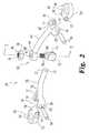
図2は、図1の交差連結装置24の交差連結器26の分解組立図である。交差連結器26は、第1コネクタ52を備えた第1架橋部材28と、第2コネクタ54を備えた第2架橋部材40を含んでいる。第1及び第2架橋部材28、40は、それら部材の各コネクタ52、54とは反対側の端部を、調整可能な連結/相互接続器66で互いに係合させることができる。交差連結器26は、ロッド23が挿通されている第1及び第2骨取付器22の間を伸長して、両取付装置を相互接続している。交差連結器26は、第1及び第2架橋部材28、40の間の角度方向の配置及びそれらの長さを変えることができるようにする連結/相互接続器66を含んでおり、脊椎に沿う解剖学的構造を回避するため、両取付装置22の間で交差連結器26の位置決めに際し調整できるようにしている。 FIG. 2 is an exploded view of the
交差連結器26は、第1端30と、反対側の第2端32とを有している第1の細長い架橋部材28を含んでいる。第1端30は、孔38と39が横方向に貫通して形成されている一対の外側に伸張している突起(prong)36と37によって画定されている第1ソケット34を含んでいる。交差連結器26は、更に、第1端42と、反対側の第2端44とを有する第2の細長い架橋部材40を含んでいる。第1端42は、孔50と51が横方向に貫通して形成されている一対の外側に伸張している突起48と49によって画定されている第2ソケット47を含んでいる。図示のように、両架橋部材28と40は、それぞれの第1端30、42とそれぞれの第2端32、44の間で円弧形状を有するため、手術で植え込まれた位置では、架橋部材28と40は凸状に湾曲して脊柱から離れており、解剖学的構造の上方に隙間を提供している。代わりの各実施形態では、部材28と40は、より多く又はより少なく円弧状になっていてもよいし、更には真っ直ぐであってもよい。 Cross-connector 26 includes a first
第1及び第2ソケット34、47は、それぞれ、第1コネクタ52と第2コネクタ54それぞれを中に受け入れることができる大きさ及び構造に作られている。第1コネクタ52と第2コネクタ54は、それぞれ、本体56と、本体56から伸張している枝部58を含んでおり、この枝部58は、第1ソケット34と第2ソケット47に対して概ね同じ大きさで、その中に挿入できる構造に作られている。枝部58は、更に、横方向に貫通して伸張する孔62を含んでおり、コネクタ52と54をソケット34と47それぞれに挿入したとき、枝部58の孔62が孔38、39、及び50、51と整列する。適切に整列させた後、ピンの形態で示されている支柱64を突起36の孔38に挿通し、孔62を通し、突起37の孔39に挿通し、コネクタ52をソケット34と枢動可能に相互接続する。同様に、適切に整列させた後、支柱64を突起48の孔50に挿通し、孔62を通し、突起49の孔51に挿通することにより、コネクタ54をソケット47と枢動可能に相互接続する。 The first and second sockets 34, 47 are each sized and configured to receive the first connector 52 and the
孔38、39、50、及び51は、何れも、内部にねじが切られていて、支柱64がボルト又はねじの形態となっていてもよい。支柱64は、圧入、溶接、又は他のやり方で各ソケットの一方又は両方の突起に固定されていてもよい。支柱64は、標準的なボルトとナットの組合せであってもよいし、又はそれを中心にした枢動を可能にすることができる、当業者に既知の他の何れの装置であってもよい。また、枝部とソケットの間の配置を逆にして、コネクタ52、54の一方又は両方がソケットを画定し、架橋部材28、40の各隣接する端部が、ソケットの中に枢動可能に連結される枝部を画定することも考えられる。 The
図4の交差連結器26の側方斜視図を参照すると、ここには、支柱64周りのコネクタ52と54の枢動運動の方向が示されている。コネクタ52と54は、各方向矢印DとEで示される上下方向に自在に枢動する。コネクタ52と54は、実質的に同一面内にあるように図示されているが、それらの平面的な位置関係は、交差連結器26を、体内で異なる高さ位置を有し、互いに対して及びコネクタ52、54に対して異なる角度方向の配置を有する骨取付器22に取り付けるときに、変えることができる。コネクタ52、54を用いて架橋部材28、40の端部の角度方向の配置を調整できるようにしているので、両骨取付器の間の相対的位置と角度方向の配置が無限に可能になり、交差連結器26の骨取付器間への取り付けが容易になる。 Referring to the side perspective view of the
1つの実施形態では、コネクタ52と54の本体56には、図1の骨取付器22との係合を容易にするために、貫通孔60が設けられている。代わりの実施形態(図示していない)では、本体56には、完全に取り囲まれた孔60は設けられていない。1つのその様な変型例では、取り囲まれた孔60の代わりに、スロットが形成された開口しているつば部(collar)が、コネクタ52と54の各本体56によって画定されている。別の形態では、コネクタ52と54の構造は、各骨取付器22と係合させるための異なる手段を有している。これに対応し、架橋部材28と40の形状と大きさは、特定の用途の求めに応じて、図示のものとは異なっていてもよい。 In one embodiment, the body 56 of the
例えば、コネクタ52、54は、各受け器部分90の端部に当接させることもできるし、又は中に各受け器部分90を少なくとも部分的には受け入れる空洞部を含んでいてもよい。なお、コネクタ52、54は、係合部材を用いて骨取付器22に最終的に固定されるまで、骨取付器22周りに回転してもよいものと理解されたい。コネクタ52、54、而して架橋部材28、40を骨取付器に対して回転方向に調整できるようにしているので、架橋部材28、40の互いに対する角度方向の配置と長さの調整が更に容易になる。 For example, the
交差連結器26は、更に、軸部68、ファスナ70、通路74を画定しているスリーブ72、を有する調整可能な連結/相互接続器66を含んでいる。連結/相互接続器66の詳細な断面図を図3に示しているが、この図は、図2に示す3−3線に沿う断面に対応している。スリーブ72は、軸部68と反対の側に位置決めされており、軸部から離れる方向に伸張している。架橋部材40は、軸部68と回転可能に係合できる構造に作られており、架橋部材28は、スリーブ72の通路74内に並進及び回転可能に係合できる構造に作られている。架橋部材40の第2端44は、端部分45を含んでおり、その中を貫通して通路46が画定されている。 The
図1及び図3から図7に示すように一体に組み立てられたとき、連結/相互接続器66の軸部68は通路46に挿通された状態である。孔60の場合の様に、通路46は、代わりに、通路46の取り囲まれた構造に代えて、軸部68を受け入れるフォーク、スロット、シム、つば部、又はブレード(可能性として幾つかを例示したのみ)として画定されていてもよい。図4に示すように、架橋部材40は、回転運動矢印Aで表わされている軸R1周りの或る範囲の回転位置に亘って動かすことができる。 When assembled together as shown in FIGS. 1 and 3 to 7, the shaft portion 68 of the coupling / interconnector 66 is inserted into the passage 46. As in the case of the
架橋部材28は、第1端30と反対の側に、スリーブ72の通路74に挿通されて、図4の範囲区分Bで表わされている、軸Tに沿う並進運動範囲を有する端部分33を画定している第2端32を含んでいる。更に、通路74と端部分33は、図4の回転運動矢印Cで表されている、通路74及びスリーブ72に対する軸R2周りの或る範囲の回転位置を取り易い寸法及び形状に作られている。 On the opposite side of the
軸部68を通路46に挿通し、端部分33を通路74に挿通し、軸R1、R2、及びTに対する選択された配置を決めた後、雌ねじ部78を有する孔76を含んでいるファスナ70を軸部68のねじ部80と係合させる。ファスナ70を回すと、スリーブ72は、端部分33を端部分45に接触させ、両者の間には、両者の間の動きに抵抗する支承関係が形成される。これに対応して、架橋部材28と40は、ファスナ70が軸部68に締め付けられ、端部分33の、端部分45と接触する側とは反対側の側部に押し付けられることで、互いに対して固定される。なお、最終的な締め付けの前に、相対的な配置の微調整を行えるものと理解すべきである。ファスナ70が最終的に締め付けられると、軸R1とR2(及び範囲AとC)に対する選択された回転配置及び範囲区画Bに沿う軸Tに対する選択された並進配置で、一対の骨取付器22の間を跨る架橋構造が出来上がる。なお、軸R1とR2は、互いに概ね直交しており、架橋部材28、40は、軸R1周りに互いに対し角度方向に調整できるものと理解すべきである。コネクタ52、54の互いに対する角度方向の配置は、架橋部材28を軸R2周り回転させることによって調整することができる。図3では、軸R1は、紙面に平行であるが、軸R2は、紙面に対し垂直であり、十字線で表わされている。並進軸Tは、図4に最もはっきりと示されているように、軸R2に平行である。 A
次に図5を参照すると、図1の交差連結装置24が描かれており、装置の或る特定の隠れている特徴は仮想線で示されている。交差連結装置24は、交差連結器26と、骨ねじ82と骨ねじ84の形態をしている一対の骨取付器とを含んでいる。骨ねじ82と84は、それぞれ、螺旋ねじ部分88を備えた細長いシャフト又は軸部86を有することができる。軸部86は、標準的なやり方で1つ又はそれ以上の骨又は骨構造に設けられた通路に螺合することができる構造に作られており、切削溝、又はセルフタッピング及び/又は自己穿孔を可能にする他の構造を設けていてもよい。軸部86には、設置を容易にするためのガイドワイヤを受け入れるために管腔が形成されていてもよく、更に、骨成長物質を配置するための窓又は他の開口部が設けられていてもよい。 Referring now to FIG. 5, the
骨ねじ82と骨ねじ84は、それぞれ、直立アーム92の間に受け入れチャネル94が画定されている頭部又は受け器部分90を有している。両アーム92は、雌ねじ部98を含んでいてもよい。図示していない代わりの実施形態では、頭部90は、受け入れチャネル94を含んではいるが、ねじ部98が設けられていないか、又はねじ部98に加えて又はこれに代えて、雄ねじ部が設けられていてよい。受け入れチャネル94は、ロッド23を含んでいる各実施形態については、追加の固定手段無しに、受け器部分90にロッド23を受動的に固定することができる構造を有するチャネルを形成していてもよい。底部分96は、凹状に湾曲し、円の一部を形成して、嵌め込み式係合の形態でその中にロッドを受け入れることができるようになっていてもよい。他の実施形態では、ロッドは骨ねじの頭部に押し当てて、又は受け器部分90内の骨ねじの頭部に隣接するキャップ又は冠部(crown)に押し当てて、配置することが考えられる。
1つの形態では、骨ねじ82と骨ねじ84は、医用等級のステンレス鋼で形成されているが、他の実施形態は、限定するわけではないが、チタン、チタン合金又は他の金属合金、及び/又は非金属組成物で構成されていてもよい。骨取付器22は、軸部86と受け器部分90が互いに対して可動である限り、限定するわけではないが、複軸式、多軸式、単軸式、単平面式の骨ねじであってもよい。1つの可動形態では、軸部86と受け器部分90は、少なくとも組み立ての幾つかの工程の間は、両者の間の相対運動を許容する「ボールジョイント」又は旋回型の連結方式で一体に係合している。別の形態では、取付装置22は、椎弓根、椎弓板、棘突起、横突起等の隣接する骨構造、又は脊椎フックに係合させるのに適した他の骨構造に係合させる1つ又は複数のフックを含んでいる。例えば、複軸式椎弓板フックの形態の骨取付器22を、ねじ82及び/又はねじ84に代えて使用してもよい。更に他の実施形態では、骨取付器22として、ステープル、骨プレート、椎体間融合装置、椎体間スペーサ、脊椎アンカー、椎骨内融合装置、骨クランプ、又は他のアンカーの形態をした骨取付構造を含むことができる。 In one form,
加えて、ロッド23は、その長さの一部又は全部に沿って中実であっても中空であってもよく、及び/又は均一の組成又は不均一の組成であってもよい。ロッド23は、剛性を有していてもよいし、又は可撓性を有しているか、少なくとも限定された脊椎運動を許容する1つ又はそれ以上の可撓部分を含んでいてもよい。ロッド23は、プレート、係留紐、ワイヤ、ケーブル、コード、膨張可能な装置、拡張可能な装置を含め、脊柱に沿って位置決め可能である、どの様な適した脊椎安定化要素と置き換えてもよく、例えば、プレート装置として形成してもよい。 In addition, the
図5に示す実施形態は、更に、交差連結器26を、骨ねじ82と84それぞれに、又は他の骨取付器に固定することができる構造に作られた2つの係合部材100と101を含んでいる。係合部材100と101は、それぞれ、頭部104とは反対側の長手方向のねじ付き軸部102、102’をそれぞれ含んでいる。係合部材100、101それぞれの頭部104は、工具係合空洞106を含んでいる。工具係合空洞106は、限定するわけではないが、六角形又はアレン型レンチ形状であってもよい。代わりの実施形態では、工具係合部は、適切な組み立て工具を係合させることができる異なる形状の構造によって設けてもよいし、工具係合部は無くてもよい。実際に、1つの代替例では、係合部材100、101は脆い破断部分を含んでおり、そこに工具を係合させて、係合部材100と101を受け器部分90の中に閾値のトルクレベルに達するまでねじ込むと、その時点で、破断部分が壊れて、係合部材100、101の残り部分から所定の個所で分離するようになっている。 The embodiment shown in FIG. 5 further includes two engagement members 100 and 101 made in a structure that can secure the cross-connector 26 to bone screws 82 and 84, respectively, or to other bone appliers. Contains. Engaging members 100 and 101 each include a threaded
係合部材100、101それぞれの長手方向のねじ付き軸部102、102’は、対応するコネクタ52と54の各孔60に挿通されて、各受け器部分90のねじ部98と係合する。いったんねじ込まれ締め付けられると、各係合部材100と101の頭部104は、対応するコネクタ52と54を押し付け、各架橋部材28と40を各受け器部分90に取り付ける。なお、頭部104は、対応する孔60に対して実質的な境界を形成している箇所を含め、コネクタ52又は54に支承関係に接触する寸法及び形状に作られているものと理解すべきである。なお、コネクタ52と54は、係合部材100と101が完全に締め付けられるまで骨取付器22の周りに回転させ、架橋部材28、40の向きの調整ができるようになっているものと理解すべきである。 The longitudinal threaded
図5は、受け器部分90内にロッド23が配置されている骨ねじ82を示している。この適用例の様々な実施形態では、受け器部分90とロッド23は、互いに及び/又は装置20の他の構成要素との関連で大きさが異なっていてもよい。係合部材100を受け器部分90に係合させると、ねじ付き軸部102の端は、ロッド23に押し付けられ、ロッド23を、底部分96又は受け器部分90の他の構造に押し付けて、ロッド23を交差連結器26及び骨ねじ82と一体構造に固定する。 FIG. 5 shows a
図5では、ねじ部98を分かり易く示すために、係合部材101は、骨ねじ84の受け器部分90と完全には係合していない状態で示されている。しかしながら、軸部102’は、その遠位端が受け器部分90内の位置91で停止するように、頭部104から伸長する或る長さを有している。位置91で、軸部102’の遠位端は、受け器部分90内のロッド23から間隔を空けた状態に保たれている。この構成では、ロッド23は、骨ねじ84及び交差連結器26に対して軸方向に自由に並進し及び移動することができ、一方、交差連結器26と骨ねじ84は、互いに一体的に連結されている。更に、係合部材100、101は、骨ねじ82、84の一方又は両方の何れに採用されてもよいし、他の骨取付器22に採用されてもよいと考えられる。 In FIG. 5, the engagement member 101 is shown in a state where it is not completely engaged with the
図示していない代わりの実施形態では、コネクタ52、54の一方又は両方は、軸部102’を有する係合部材101が骨取付器22に係合されたときに、それぞれの隣接するロッド23に接触する構造を含んでいてもよい。従って、係合部材101は、締め付けられたときに、受け器部分90内のロッド23から間隔を空けた状態に保たれ、一方、コネクタ52、54は、受け器部分90を受け入れるための窪みを含んでいるか、そこから遠位側にロッド23に向けて伸長していて、ロッド23に接触してロッド23を骨取付器の受け器部分90に確実に係合させる構造を含んでいる。 In an alternative embodiment, not shown, one or both of the
なお、図5に示す実施形態は、骨ねじ82と骨ねじ84の受け器部分90の頂部又は近位端99が異なる高さの平面内にあることを示していることも、理解すべきである。交差連結器26は、たとえ、受け器部分90の近位端99又は骨取付器22の他の構造が異なる高さ平面、異なる角度方向の位置にあっても、コネクタ52と54が支柱64周りに枢動するので、これらと適切に係合させることができる。図示していないが、両骨取付器の近位端99同士の間の高さの差異は、別の実施形態では、より大きくても、より小さくても、或いは正に同じであってもよいと理解される。 It should also be understood that the embodiment shown in FIG. 5 shows that the top or proximal end 99 of the
図6は、交差連結装置24の斜視組立図であり、本図では、先に説明した同様の特徴には同様の符号を付して示している。この実施形態では、連結具107が使用されている。連結具107には、第1端108と反対側の第2端109があり、雌ねじ部分112を有する長手方向のねじ付き軸部110を含んでいる。この第1端108には、更に、工具協働部分114が形成されている。連結具107の長手方向のねじ付き軸部110は、連結具107が回転され、骨ねじ82と84の受け器部分90の中にねじ込まれたときに、ねじ部98と係合する構造に作られている。図示してはいないが、図6の実施形態は、骨ねじ82、84の各受け器部分90に通す1つ又は複数のロッド23を含むと考えられる。ロッド23をロッド受け入れチャネル94の中に入れて、連結具107をねじ部98に係合させると、第2端109がロッド23に押し付けられ、受け器部分90とロッド23の間に一体的な係合が作り出される。 FIG. 6 is a perspective assembly view of the
雌ねじ部分112は、例えば、係合部材100を、コネクタ52と54のうち、隣接するいずれかのコネクタの孔60に挿通したときに、係合部材100のねじ付き軸部102と係合する構造に作られている。連結具107を受け器部分90内に締め付け、係合部材100を雌ねじ部分112内に締め付けると、交差連結器26は、骨ねじ82と84又は他の骨取付器22と一体構造に係止される。骨ねじ82と骨ねじ84は、共に連結具107を使用しているように示されているが、代わりの実施形態では、骨ねじ82と骨ねじ84の一方又は両方に連結具107が無くてもよいことを理解されたい。更に、図6には示していない代わりの骨取付器22に連結具107を使用することも考えられる。 The female screw portion 112 has a structure that engages with the threaded
交差連結装置24の代わりの実施形態を、図7に側方平面図で示しており、本図では、或る特定の隠れた特徴を仮想線で示し、また、これまでに説明したものと同様の特徴は同様の符号を付して示している。交差連結器26のコネクタ52は、椎弓板フック116の形態をした骨取付器22に接続されているように図示されている。椎弓板フック116は、骨又は骨表面に係合させる構造に作られているフック部分118と、近位側頭部又は受け器部分124を含んでいる。受け器部分124は、内部に雌ねじ部127が設けられた一対の直立するアーム122によって形成されている受け入れ溝126を更に含んでいる。係合部材100の様な係合部材を、孔60に挿通し、ねじ部127と係合させて、コネクタ52と、椎弓板フック116と、ロッド又は受け入れ溝126内に配置されている他の細長い要素との間に一体構造を形成する。 An alternative embodiment of the
フック116の反対側には、別の実施形態による骨取付器が示されている。コネクタ54は、近位側に伸張している柱132とは反対側の遠位側骨係合部分130を含んでいる骨アンカー128の形態をした骨取付器22に接続されている状態で示されている。柱132の周りには、受け器部分136を含んでいる連結具クランプ134が係合されている。受け器部分136と反対の側には、柱132が挿通される孔141が設けられている柱係合部分138が在る。連結具クランプ134は、更に、ロッド接合面ワッシャ138と柱接合面ワッシャ140を含んでいる。ワッシャ138とワッシャ140の互いに向かい合う側には、一組の相互噛み合い歯142が設けられている。相互噛み合い歯142は、ロッド23の骨アンカー128に対する角度方向の配置を変更できるように、ワッシャ138とワッシャ140を係止可能に位置決めすることができる構造に作られている。しかしながら、一旦、係合部材100を孔60に挿通して、受け器部分136付近に設けられているねじ付き孔144と完全に係合させると、相互噛み合い歯142は係止状態になり、ロッド23は両ワッシャ138、140を押圧して互いに接触させることになる。このことは、ねじ付き軸部102がロッド23を押圧し、ワッシャ138と140を共に押圧し、孔141を引いて柱132に緊密に押し付け、コネクタ54とロッド23と骨アンカー128との間に一体構造を形成することによって生じる。骨アンカー128又は他の形態を含む骨取付器22は、例えば、TSRH-3D(登録商標)脊椎システムという商標名で市販されている。 On the opposite side of the
代わりの実施形態では、交差連結装置24は、両係合部材100、101及び/又はコネクタ52、54の孔60を有しない。これら実施形態には、交差連結器26を骨取付器22と接続するための様々な手段が含まれている。その様な手段としては、限定するわけではないが、スナップリング、ナット、ピン、圧入嵌合、スナップ嵌合、クランプ、接着材、及び融合が挙げられる。例えば、係合部材100、101は、雄ねじが切られた軸部を有するように示されている。他の実施形態では、例えば、捩り係止、スナップ嵌合、干渉嵌合、滑動嵌合、クランプ、拡張嵌合、雌ねじが切られた軸部などを含め、受け器部分32に係合させるための他の構造を有する係合部材100、101が考えられる。接続手段が変更されると、コネクタ52及び54側の対応する構造も変更されることになる。ロッド23を含んでいる実施形態では、ロッド23を一方又は両方の骨取付器22に固定する方法も変更されることになる。 In an alternative embodiment, the
交差連結装置24の構成要素は、医用等級のステンレス鋼で構成することができる。他の実施形態は、限定するわけではないが、チタン、チタン合金又は他の金属合金、及び/又は非金属組成物で構成してもよい。 The components of the
以上、本発明を図面に例示し上記説明文で詳細に説明してきたが、それらは説明が目的であって、何ら制限を課すものではないと考えられるべきであり、選択された実施形態を図示し説明したに過ぎないこと、及びここに説明し又は特許請求の範囲によって定義される本発明の範囲内に含まれる全ての変更、等価物、及び修正は保護の対象とされるよう要求すること、を理解頂きたい。ここに提供しているあらゆる実験、実験実施例、又は実験結果は、本発明を例証することを意図しており、本発明の範囲を限定又は制約するものと解釈すべきではない。また、ここに述べたあらゆる理論、作動機構、論証、又は知見は、本発明の理解を更に深めるためのものであり、本発明を如何なる意味でもその様な理論、作動機構、論証、又は知見に限定する意図はない。特許請求の範囲を読む際に、「或る」「1つの」「少なくとも1つの」及び「少なくとも一部の」の様な語は、別に特に指定のない限り、特許請求の範囲を唯1つの項目に限定するよう意図するものではない。更に、「少なくとも一部」及び/又は「或る部分」という用語を使用する場合、特許請求の範囲は、別に特に指定のない限り、一部及び/又は項目全体を含むことになる。 While the invention has been illustrated in the drawings and described in detail in the foregoing description, it is to be understood that they are for purposes of illustration and are not to be construed as limiting in any way. Require that all changes, equivalents, and modifications included within the scope of the invention as illustrated and described herein or defined by the claims be protected. I want you to understand. Any experiment, experimental example, or experimental result provided herein is intended to be illustrative of the present invention and should not be construed as limiting or limiting the scope of the invention. In addition, any theory, operation mechanism, proof or knowledge described herein is for further understanding of the present invention, and the present invention is not limited to such theory, operation mechanism, proof or knowledge in any way. There is no intention to limit. In reading the claims, terms such as “a”, “one”, “at least one” and “at least some” refer to the claims unless otherwise specified. It is not intended to be limited to items. Further, when the terms “at least part” and / or “some part” are used, the claims are intended to include a part and / or the whole item unless specifically stated otherwise.
Claims (32)
Translated fromJapanese前記2つの骨取付器を相互接続し、前記2つの骨取付器を分離している距離を、調整可能に跨ぐように構成された交差連結器とを備える装置であって、
前記交差連結器は、
第1端部分と前記第1端部分に対向する第1コネクタとを備える第1部材であって、前記第1コネクタは、前記2つの骨取付器のうちの第1の骨取付器に係合するように構成された本体を含み且つ前記第1部材に対して枢動可能である、第1部材と、
第2端部分と前記第2端部分に対向する第2コネクタとを備える第2部材であって、前記第2コネクタは、前記2つの骨取付器のうちの第2の骨取付器に係合するように構成された本体を含み且つ前記第2部材に対して枢動可能である、第2部材と、
前記第1部材と前記第2部材を共に相互接続するように、前記第1端部分と前記第2端部分の間に位置決めされる相互接続器、とを含んでおり、
前記装置は、さらに、2つの係合部材を備えており、前記2つの係合部材のうちの第1の係合部材は、前記第1コネクタが前記2つの骨取付器のうちの前記第1の骨取付器と整列したときに、前記第1コネクタと前記第1の骨取付器を係合させて、前記第1部材を前記第1の骨取付器に固定するように構成されており、前記2つの係合部材のうちの第2の係合部材は、前記第2コネクタが前記2つの骨取付器のうちの前記第2の骨取付器と整列したときに、前記第2コネクタと前記第2の骨取付器を係合させて、前記第2部材を前記第2の骨取付器に固定するように構成されている、装置。Two bone appliers configured to anchor to the bone;
A device comprising: a cross-connector configured to adjustably straddle a distance separating the two bone appliers, interconnecting the two bone appliers;
The cross-connector is
A first member comprising a first end portion and a first connector facing the first end portion, wherein the first connector engages a first bone applier of the two bone appliers. A first member including a body configured to be pivotable relative to the first member;
A second member comprising a second end portion and a second connector facing the second end portion, wherein the second connector engages with a second bone applier of the two bone appliers. A second member including a body configured to be pivotable relative to the second member;
An interconnector positioned between the first end portion and the second end portion so as to interconnect the first member and the second member together;
The apparatus further includes two engagement members, wherein the first engagement member of the two engagement members is the first connector of the two bone appliers. The first connector and the first bone applier are engaged to secure the first member to the first bone applier when aligned with the bone applier, A second engagement member of the two engagement members is configured such that when the second connector is aligned with the second bone applier of the two bone appliers, the second connector and the An apparatus configured to engage a second bone applier to secure the second member to the second bone applier.
前記第2部材と前記第2コネクタのうちの一方は枝部を含み、前記第2部材と前記第2コネクタのうちの他方はソケットを含んでおり、前記枝部とソケットは互いに枢動可能に連結されている、請求項1に記載の装置。One of the first member and the first connector includes a branch, the other of the first member and the first connector includes a socket, and the branch and the socket are pivotable with respect to each other. Are connected,
One of the second member and the second connector includes a branch, the other of the second member and the second connector includes a socket, and the branch and the socket are pivotable with respect to each other. The apparatus of claim 1, which is connected.
第1及び第2骨取付器を、それぞれ、対応する所望の骨格部位に取り付ける工程と、
第1コネクタが枢動可能に取り付けられている第1部材と、第2コネクタが枢動可能に取り付けられている第2部材と、を含んでいる交差連結器であって、前記第1部材と前記第2部材は、前記第1コネクタと前記第2コネクタの間で、調整可能な相互接続器によって相互接続されている、交差連結器を提供する工程と、
前記交差連結器を前記相互接続器で調整して、前記第1部材の前記第2部材に対する並進方向の位置と角度方向の位置を変える工程と、
前記第1コネクタを前記第1骨取付器に固定する工程と、
前記第2コネクタを前記第2骨取付器に固定する工程と、
から成る方法。In a method using a multi-axis cross-connector,
Attaching the first and second bone appliers to the corresponding desired skeletal site,
A cross-connector comprising: a first member to which a first connector is pivotally attached; and a second member to which a second connector is pivotally attached, wherein the first member; Providing a cross-connector wherein the second member is interconnected between the first connector and the second connector by an adjustable interconnector;
Adjusting the cross-connector with the interconnect to change the translational position and the angular position of the first member relative to the second member;
Securing the first connector to the first bone applier;
Securing the second connector to the second bone applier;
A method consisting of:
第1の細長い部材及び第2の細長い部材と、第1コネクタを前記第1の細長い部材の端部に枢動可能に連結するための手段と、を含んでいる交差連結器であって、更に、前記第1の細長い部材と前記第2の細長い部材の互いに対する軸方向及び角度方向の並進が許容されるように、前記第1及び第2の細長い部材を互いに調整可能に接続するための、前記端部から離れている手段を更に含んでいる、交差連結器と、
少なくとも前記第1の細長い部材を横断する方向に前記受け器部分に挿通されている第1の細長い脊椎安定化要素と、
前記第1コネクタと、前記第1の細長い脊椎安定化要素と、前記第1骨取付器を、共に固定するための手段と、を備えている装置。A first bone applier including a receiver portion;
A cross-connector comprising: a first elongate member and a second elongate member; and means for pivotally connecting a first connector to an end of the first elongate member, , To adjustably connect the first and second elongate members to each other such that axial and angular translation of the first elongate member and the second elongate member relative to each other is permitted. A cross-connector further comprising means remote from the end;
A first elongate spinal stabilization element that is inserted through the receptacle portion in a direction transverse to at least the first elongate member;
An apparatus comprising: the first connector; the first elongate spinal stabilization element; and means for securing the first bone applier together.
それぞれ受け器部分を含んでいる2つの骨取付器を、それぞれ、患者の脊椎に沿うそれぞれの所望の部位に取り付ける工程と、
2つの細長い脊椎安定化要素をそれぞれ、別々の前記骨取付器の前記受け器部分に位置決めする工程と、
前記骨取付器のうち一方の骨取付器から他方の取付装置まで跨るように前記交差連結器を提供する工程であって、前記交差連結器は、2つの架橋部材と、前記2つの骨取付器の間に前記2つの架橋部材を共に調整可能に接続する相互接続器と、を含んでおり、前記2つの架橋部材のそれぞれは、前記架橋部材に枢動可能に連結されているコネクタを含んでいる、前記交差連結器を提供する工程と、
前記2つの架橋部材の互いに対する並進方向及び回転方向の位置を、前記相互接続器により調整する工程と、
前記コネクタの各々の前記骨取付器に対する平面上の及び角度方向の位置を調整する工程と、
前記架橋部材の前記コネクタの各々を、別々の前記骨取付器に固定して、前記骨取付器と、前記細長い脊椎安定化要素と、前記交差連結器を共に1つの構造にして固定する工程と、から成る方法。A method of using a cross-connector,
Attaching two bone appliers, each including a receptacle portion, to a respective desired site along the patient's spine;
Positioning two elongated spinal stabilization elements, respectively, in the receiver portions of separate bone appliers;
Providing the cross-connector so as to straddle from one of the bone applicators to the other attachment device, the cross-connector including two bridging members and the two bone applicators An interconnector for adjustably connecting the two bridging members together, each of the two bridging members including a connector pivotally coupled to the bridging member. Providing the cross-connector;
Adjusting the translational and rotational positions of the two bridging members relative to each other by the interconnector;
Adjusting the planar and angular position of each of the connectors relative to the bone applier;
Securing each of the connectors of the bridging member to a separate bone applier, and securing the bone applier, the elongated spinal stabilization element, and the cross-connector together in one structure; A method consisting of
Applications Claiming Priority (3)
| Application Number | Priority Date | Filing Date | Title |
|---|---|---|---|
| US11/401,732US7837714B2 (en) | 2006-04-10 | 2006-04-10 | Methods and devices for the interconnection of bone attachment devices |
| US11/401,732 | 2006-04-10 | ||
| PCT/US2007/066212WO2007121128A1 (en) | 2006-04-10 | 2007-04-09 | Methods and devices for the interconnection of bone attachment devices |
Publications (2)
| Publication Number | Publication Date |
|---|---|
| JP2009533173Atrue JP2009533173A (en) | 2009-09-17 |
| JP5006926B2 JP5006926B2 (en) | 2012-08-22 |
Family
ID=38480563
Family Applications (1)
| Application Number | Title | Priority Date | Filing Date |
|---|---|---|---|
| JP2009505558AExpired - Fee RelatedJP5006926B2 (en) | 2006-04-10 | 2007-04-09 | Method and apparatus for interconnecting bone appliers |
Country Status (6)
| Country | Link |
|---|---|
| US (1) | US7837714B2 (en) |
| EP (1) | EP2004077A1 (en) |
| JP (1) | JP5006926B2 (en) |
| KR (1) | KR20090007405A (en) |
| CN (1) | CN101426437A (en) |
| WO (1) | WO2007121128A1 (en) |
Cited By (3)
| Publication number | Priority date | Publication date | Assignee | Title |
|---|---|---|---|---|
| JP2016512098A (en)* | 2013-03-15 | 2016-04-25 | ブラックストーン メディカル,インコーポレイテッド | Cross brace bilateral spinal rod connector |
| KR20160070311A (en)* | 2014-12-09 | 2016-06-20 | 한림대학교 산학협력단 | Screw guide device for control for surgical treatment |
| WO2017141459A1 (en) | 2016-02-15 | 2017-08-24 | 株式会社アスロメディカル | Transverse, and surgical instrument |
Families Citing this family (81)
| Publication number | Priority date | Publication date | Assignee | Title |
|---|---|---|---|---|
| US8480712B1 (en) | 2004-01-06 | 2013-07-09 | Nuvasive, Inc. | System and method for performing spinal fixation |
| US8114158B2 (en) | 2004-08-03 | 2012-02-14 | Kspine, Inc. | Facet device and method |
| WO2006058221A2 (en) | 2004-11-24 | 2006-06-01 | Abdou Samy M | Devices and methods for inter-vertebral orthopedic device placement |
| US8496686B2 (en)* | 2005-03-22 | 2013-07-30 | Gmedelaware 2 Llc | Minimally invasive spine restoration systems, devices, methods and kits |
| US7722648B2 (en)* | 2006-04-10 | 2010-05-25 | Warsaw Orthopedic, Inc. | Crosslink interconnection of bone attachment devices |
| US8568453B2 (en)* | 2007-01-29 | 2013-10-29 | Samy Abdou | Spinal stabilization systems and methods of use |
| US8926667B2 (en)* | 2007-02-09 | 2015-01-06 | Transcendental Spine, Llc | Connector |
| US8926669B2 (en)* | 2007-02-27 | 2015-01-06 | The Center For Orthopedic Research And Education, Inc. | Modular polyaxial pedicle screw system |
| US8167912B2 (en) | 2007-02-27 | 2012-05-01 | The Center for Orthopedic Research and Education, Inc | Modular pedicle screw system |
| GB0707285D0 (en)* | 2007-04-17 | 2007-05-23 | Burke John | Implantable apparatus for modulation of skeletal growth |
| US9474554B2 (en)* | 2007-10-23 | 2016-10-25 | Lee A. Strnad | Spinal rod cross connector |
| US20090112266A1 (en)* | 2007-10-25 | 2009-04-30 | Industrial Technology Research Institute | Spinal dynamic stabilization device |
| US8197515B2 (en)* | 2008-02-18 | 2012-06-12 | Expanding Orthopedics Inc. | Cross-connector assembly |
| US9060813B1 (en) | 2008-02-29 | 2015-06-23 | Nuvasive, Inc. | Surgical fixation system and related methods |
| EP2352449B1 (en) | 2008-11-03 | 2018-02-21 | Synthes GmbH | Adjustable rod assembly |
| US8828058B2 (en) | 2008-11-11 | 2014-09-09 | Kspine, Inc. | Growth directed vertebral fixation system with distractible connector(s) and apical control |
| GB0822507D0 (en)* | 2008-12-10 | 2009-01-14 | Karnezis Ioannis | Surgical device for correction of spinal deformities |
| US8246665B2 (en)* | 2008-12-22 | 2012-08-21 | Life Spine, Inc. | Posterior cervical cross connector assemblies |
| US8357182B2 (en) | 2009-03-26 | 2013-01-22 | Kspine, Inc. | Alignment system with longitudinal support features |
| US8246657B1 (en) | 2009-06-29 | 2012-08-21 | Nuvasive, Inc. | Spinal cross connector |
| WO2011022723A1 (en)* | 2009-08-21 | 2011-02-24 | K2M, Inc. | Transverse rod connector |
| US9168071B2 (en) | 2009-09-15 | 2015-10-27 | K2M, Inc. | Growth modulation system |
| US8764806B2 (en) | 2009-12-07 | 2014-07-01 | Samy Abdou | Devices and methods for minimally invasive spinal stabilization and instrumentation |
| US9827013B2 (en) | 2009-12-08 | 2017-11-28 | Concept Spine Ltd. | Surgical device for correction of spinal deformities |
| US9198696B1 (en) | 2010-05-27 | 2015-12-01 | Nuvasive, Inc. | Cross-connector and related methods |
| KR101030065B1 (en)* | 2010-07-23 | 2011-04-19 | 주식회사 지에스메디칼 | Transverse rod connector |
| US8523911B2 (en)* | 2010-09-16 | 2013-09-03 | Globus Medical, Inc. | Transverse connector including locking cap with bearing surface |
| US8491641B2 (en) | 2010-09-28 | 2013-07-23 | Spinofix, Inc. | Pedicle screws and dynamic adaptors |
| US20120095510A1 (en)* | 2010-10-18 | 2012-04-19 | Raj Nihalani | Cross connectors |
| US9247964B1 (en) | 2011-03-01 | 2016-02-02 | Nuasive, Inc. | Spinal Cross-connector |
| US9387013B1 (en) | 2011-03-01 | 2016-07-12 | Nuvasive, Inc. | Posterior cervical fixation system |
| US8672978B2 (en)* | 2011-03-04 | 2014-03-18 | Zimmer Spine, Inc. | Transverse connector |
| CN102160814A (en)* | 2011-03-22 | 2011-08-24 | 邱勇 | Spinal resetting device |
| JP6158176B2 (en) | 2011-06-03 | 2017-07-05 | ケイツーエム インコーポレイテッドK2M,Inc. | Spine correction system |
| US8845728B1 (en) | 2011-09-23 | 2014-09-30 | Samy Abdou | Spinal fixation devices and methods of use |
| WO2014172632A2 (en) | 2011-11-16 | 2014-10-23 | Kspine, Inc. | Spinal correction and secondary stabilization |
| US9451987B2 (en) | 2011-11-16 | 2016-09-27 | K2M, Inc. | System and method for spinal correction |
| US9468468B2 (en) | 2011-11-16 | 2016-10-18 | K2M, Inc. | Transverse connector for spinal stabilization system |
| US9468469B2 (en) | 2011-11-16 | 2016-10-18 | K2M, Inc. | Transverse coupler adjuster spinal correction systems and methods |
| US8920472B2 (en) | 2011-11-16 | 2014-12-30 | Kspine, Inc. | Spinal correction and secondary stabilization |
| US8956361B2 (en) | 2011-12-19 | 2015-02-17 | Amendia, Inc. | Extended tab bone screw system |
| US9125691B2 (en)* | 2011-12-23 | 2015-09-08 | Amendia, Inc. | Transverse crosslink device |
| US20130226240A1 (en) | 2012-02-22 | 2013-08-29 | Samy Abdou | Spinous process fixation devices and methods of use |
| US9198767B2 (en) | 2012-08-28 | 2015-12-01 | Samy Abdou | Devices and methods for spinal stabilization and instrumentation |
| US9339309B1 (en) | 2012-10-11 | 2016-05-17 | Nuvasive, Inc. | Systems and methods for inserting cross-connectors |
| US9320617B2 (en) | 2012-10-22 | 2016-04-26 | Cogent Spine, LLC | Devices and methods for spinal stabilization and instrumentation |
| US10485587B2 (en)* | 2012-11-06 | 2019-11-26 | Globus Medical, Inc | Low profile connectors |
| US10335206B2 (en)* | 2012-11-06 | 2019-07-02 | Globus Medical, Inc. | Low profile connectors |
| US9700435B2 (en) | 2013-03-14 | 2017-07-11 | Warsaw Orthopedic, Inc. | Surgical delivery system and method |
| CN103381105B (en)* | 2013-06-06 | 2015-09-30 | 雷伟 | A kind of waist ilium joint control and waist ilium associating fixing means thereof |
| US9468471B2 (en) | 2013-09-17 | 2016-10-18 | K2M, Inc. | Transverse coupler adjuster spinal correction systems and methods |
| US9707015B2 (en) | 2014-01-14 | 2017-07-18 | Life Spine, Inc. | Implant for immobilizing cervical vertebrae |
| US9763703B2 (en) | 2015-05-05 | 2017-09-19 | Degen Medical, Inc. | Cross connectors, kits, and methods |
| TW201707653A (en)* | 2015-08-18 | 2017-03-01 | Pao Nan Biotech Co Ltd | Apparatus for preventing resected fibula sections from bone mergence and connection capable of effectively preventing resected fibula from rigid re-mergence |
| US10987129B2 (en) | 2015-09-04 | 2021-04-27 | Medos International Sarl | Multi-shield spinal access system |
| US11744447B2 (en) | 2015-09-04 | 2023-09-05 | Medos International | Surgical visualization systems and related methods |
| US11439380B2 (en) | 2015-09-04 | 2022-09-13 | Medos International Sarl | Surgical instrument connectors and related methods |
| CN113143355A (en) | 2015-09-04 | 2021-07-23 | 美多斯国际有限公司 | Multi-shield spinal access system |
| US11672562B2 (en) | 2015-09-04 | 2023-06-13 | Medos International Sarl | Multi-shield spinal access system |
| US12150636B2 (en) | 2015-09-04 | 2024-11-26 | Medos International Sárl | Surgical instrument connectors and related methods |
| US10857003B1 (en) | 2015-10-14 | 2020-12-08 | Samy Abdou | Devices and methods for vertebral stabilization |
| WO2017107883A1 (en)* | 2015-12-23 | 2017-06-29 | 马向阳 | Screw-rod fixation device specially used for posterior atlantoaxial vertebrae |
| US10321939B2 (en) | 2016-05-18 | 2019-06-18 | Medos International Sarl | Implant connectors and related methods |
| US10517647B2 (en) | 2016-05-18 | 2019-12-31 | Medos International Sarl | Implant connectors and related methods |
| US10413330B2 (en)* | 2016-08-09 | 2019-09-17 | Warsaw Orthopedic, Inc. | Spinal implant system and method |
| US10744000B1 (en) | 2016-10-25 | 2020-08-18 | Samy Abdou | Devices and methods for vertebral bone realignment |
| US10973648B1 (en) | 2016-10-25 | 2021-04-13 | Samy Abdou | Devices and methods for vertebral bone realignment |
| US10398476B2 (en) | 2016-12-13 | 2019-09-03 | Medos International Sàrl | Implant adapters and related methods |
| US10492835B2 (en) | 2016-12-19 | 2019-12-03 | Medos International Sàrl | Offset rods, offset rod connectors, and related methods |
| US10238432B2 (en) | 2017-02-10 | 2019-03-26 | Medos International Sàrl | Tandem rod connectors and related methods |
| US10561454B2 (en) | 2017-03-28 | 2020-02-18 | Medos International Sarl | Articulating implant connectors and related methods |
| US10966761B2 (en) | 2017-03-28 | 2021-04-06 | Medos International Sarl | Articulating implant connectors and related methods |
| US20190117272A1 (en)* | 2017-10-22 | 2019-04-25 | Astura Medical Inc. | Variable screw top cross connector |
| US11076890B2 (en) | 2017-12-01 | 2021-08-03 | Medos International Sàrl | Rod-to-rod connectors having robust rod closure mechanisms and related methods |
| US10993746B2 (en)* | 2018-05-03 | 2021-05-04 | K2M, Inc. | Head to head transverse connector |
| US11179248B2 (en) | 2018-10-02 | 2021-11-23 | Samy Abdou | Devices and methods for spinal implantation |
| US10893894B2 (en) | 2019-04-24 | 2021-01-19 | Aesculap Implant Systems, Llc | Transverse coupling for surgical implant extensions |
| US11076891B2 (en)* | 2019-06-23 | 2021-08-03 | Premia Spine Ltd. | Bi-directional motion spinal implant |
| KR20220059861A (en)* | 2020-11-03 | 2022-05-10 | 주식회사 솔고 바이오메디칼 | Cross link device for cervical spine |
| US11331125B1 (en) | 2021-10-07 | 2022-05-17 | Ortho Inventions, Llc | Low profile rod-to-rod coupler |
| CN114404010A (en)* | 2021-12-23 | 2022-04-29 | 山东师范大学 | Adjustable vertebral lamina hook internal fixation device for lumbar isthmus fissure |
Citations (7)
| Publication number | Priority date | Publication date | Assignee | Title |
|---|---|---|---|---|
| JPH0716237A (en)* | 1991-05-17 | 1995-01-20 | Jean Louis Vignaud | An interconnecting device that facilitates spinal osteosynthesis tightening |
| US5980521A (en)* | 1995-03-30 | 1999-11-09 | Sdgi Holdings,Inc. | Top-tightening transverse connector for a spinal fixation system |
| JP2000033091A (en)* | 1998-07-06 | 2000-02-02 | Solco Surgical Instr Co Ltd | Spine fixing device |
| JP2001037767A (en)* | 1999-08-02 | 2001-02-13 | Kyowa Tokei Kogyo Kk | Bone adjuster |
| US20050216005A1 (en)* | 2001-05-17 | 2005-09-29 | Howland Robert S | Selective axis anchor screw posterior lumbar plating system |
| WO2005096974A2 (en)* | 2004-03-31 | 2005-10-20 | Depuy Spine, Inc. | Head-to-head connector spinal fixation system |
| JP2006503672A (en)* | 2002-10-28 | 2006-02-02 | エスディージーアイ・ホールディングス・インコーポレーテッド | Multi-axis cross-connect system for spinal implants |
Family Cites Families (36)
| Publication number | Priority date | Publication date | Assignee | Title |
|---|---|---|---|---|
| DE3711091A1 (en)* | 1987-04-02 | 1988-10-13 | Kluger Patrick | DEVICE FOR SETTING UP A SPINE WITH A DAMAGED SPINE |
| US5084049A (en)* | 1989-02-08 | 1992-01-28 | Acromed Corporation | Transverse connector for spinal column corrective devices |
| US5261913A (en)* | 1989-07-26 | 1993-11-16 | J.B.S. Limited Company | Device for straightening, securing, compressing and elongating the spinal column |
| WO1991016020A1 (en)* | 1990-04-26 | 1991-10-31 | Danninger Medical Technology, Inc. | Transpedicular screw system and method of use |
| US5133716A (en)* | 1990-11-07 | 1992-07-28 | Codespi Corporation | Device for correction of spinal deformities |
| WO1995010238A1 (en)* | 1993-10-08 | 1995-04-20 | Chaim Rogozinski | Spinal treatment apparatus and method including multi-directional attachment member |
| US5522816A (en)* | 1994-03-09 | 1996-06-04 | Acromed Corporation | Transverse connection for spinal column corrective devices |
| US5630816A (en)* | 1995-05-01 | 1997-05-20 | Kambin; Parviz | Double barrel spinal fixation system and method |
| US5752955A (en)* | 1995-10-30 | 1998-05-19 | Fastenetix, L.L.C. | Sliding shaft variable length cross-link device for use with dual rod apparatus |
| US5667507A (en)* | 1995-12-04 | 1997-09-16 | Fastenetix, Llc | Compression locking variable length cross-link device for use with dual rod apparatus |
| US5709684A (en)* | 1995-12-04 | 1998-01-20 | Fastenetix, Llc | Advanced compression locking variable length cross-link device |
| US5707372A (en)* | 1996-07-11 | 1998-01-13 | Third Millennium Engineering, Llc. | Multiple node variable length cross-link device |
| US5885284A (en)* | 1996-07-11 | 1999-03-23 | Third Millennium Engineering, L.L.C. | Hinged variable length cross-link device |
| US5980523A (en)* | 1998-01-08 | 1999-11-09 | Jackson; Roger | Transverse connectors for spinal rods |
| US6283967B1 (en)* | 1999-12-17 | 2001-09-04 | Synthes (U.S.A.) | Transconnector for coupling spinal rods |
| US6238396B1 (en)* | 1999-10-07 | 2001-05-29 | Blackstone Medical, Inc. | Surgical cross-connecting apparatus and related methods |
| US6217578B1 (en)* | 1999-10-19 | 2001-04-17 | Stryker Spine S.A. | Spinal cross connector |
| US6432108B1 (en)* | 2000-01-24 | 2002-08-13 | Depuy Orthopaedics, Inc. | Transverse connector |
| FR2804314B1 (en)* | 2000-01-27 | 2003-01-31 | Scientx | INTERVERTEBRAL CONNECTION DEVICE WITH A CONNECTION BAR FOR FIXING A CONNECTING ROD |
| US6261288B1 (en)* | 2000-02-08 | 2001-07-17 | Roger P. Jackson | Implant stabilization and locking system |
| US6872208B1 (en)* | 2000-10-06 | 2005-03-29 | Spinal Concepts, Inc. | Adjustable transverse connector |
| DE10101478C2 (en)* | 2001-01-12 | 2003-03-27 | Biedermann Motech Gmbh | connecting element |
| US6802844B2 (en) | 2001-03-26 | 2004-10-12 | Nuvasive, Inc | Spinal alignment apparatus and methods |
| GB0120076D0 (en)* | 2001-08-17 | 2001-10-10 | Schlumberger Holdings | Measurement of curvature of a subsurface borehole, and use of such measurement in directional drilling |
| US7261713B2 (en) | 2001-10-09 | 2007-08-28 | Synthes (Usa) | Adjustable fixator |
| US20030114853A1 (en)* | 2001-10-12 | 2003-06-19 | Ian Burgess | Polyaxial cross connector |
| JP2003232314A (en)* | 2002-02-08 | 2003-08-22 | Showa Ika Kohgyo Co Ltd | Rod interval retaining tool |
| US6699248B2 (en)* | 2002-05-09 | 2004-03-02 | Roger P. Jackson | Multiple diameter tangential set screw |
| US7066938B2 (en)* | 2002-09-09 | 2006-06-27 | Depuy Spine, Inc. | Snap-on spinal rod connector |
| US8029543B2 (en)* | 2002-10-28 | 2011-10-04 | Warsaw Othopedic, Inc. | Multi-axial, cross-link connector system for spinal implants |
| US20050215005A1 (en)* | 2003-03-06 | 2005-09-29 | Lsi Logic Corporation | Capacitor with stoichiometrically adjusted dielectric and method of fabricating same |
| US7744633B2 (en)* | 2003-10-22 | 2010-06-29 | Pioneer Surgical Technology, Inc. | Crosslink for securing spinal rods |
| US7083622B2 (en)* | 2003-11-10 | 2006-08-01 | Simonson Peter M | Artificial facet joint and method |
| US7104993B2 (en)* | 2004-02-10 | 2006-09-12 | Atlas Spine, Inc. | Cross link system |
| US7717939B2 (en)* | 2004-03-31 | 2010-05-18 | Depuy Spine, Inc. | Rod attachment for head to head cross connector |
| US7722648B2 (en)* | 2006-04-10 | 2010-05-25 | Warsaw Orthopedic, Inc. | Crosslink interconnection of bone attachment devices |
- 2006
- 2006-04-10USUS11/401,732patent/US7837714B2/enactiveActive
- 2007
- 2007-04-09EPEP07760301Apatent/EP2004077A1/ennot_activeWithdrawn
- 2007-04-09WOPCT/US2007/066212patent/WO2007121128A1/enactiveApplication Filing
- 2007-04-09JPJP2009505558Apatent/JP5006926B2/ennot_activeExpired - Fee Related
- 2007-04-09KRKR1020087027426Apatent/KR20090007405A/ennot_activeWithdrawn
- 2007-04-09CNCNA2007800139008Apatent/CN101426437A/enactivePending
Patent Citations (7)
| Publication number | Priority date | Publication date | Assignee | Title |
|---|---|---|---|---|
| JPH0716237A (en)* | 1991-05-17 | 1995-01-20 | Jean Louis Vignaud | An interconnecting device that facilitates spinal osteosynthesis tightening |
| US5980521A (en)* | 1995-03-30 | 1999-11-09 | Sdgi Holdings,Inc. | Top-tightening transverse connector for a spinal fixation system |
| JP2000033091A (en)* | 1998-07-06 | 2000-02-02 | Solco Surgical Instr Co Ltd | Spine fixing device |
| JP2001037767A (en)* | 1999-08-02 | 2001-02-13 | Kyowa Tokei Kogyo Kk | Bone adjuster |
| US20050216005A1 (en)* | 2001-05-17 | 2005-09-29 | Howland Robert S | Selective axis anchor screw posterior lumbar plating system |
| JP2006503672A (en)* | 2002-10-28 | 2006-02-02 | エスディージーアイ・ホールディングス・インコーポレーテッド | Multi-axis cross-connect system for spinal implants |
| WO2005096974A2 (en)* | 2004-03-31 | 2005-10-20 | Depuy Spine, Inc. | Head-to-head connector spinal fixation system |
Cited By (6)
| Publication number | Priority date | Publication date | Assignee | Title |
|---|---|---|---|---|
| JP2016512098A (en)* | 2013-03-15 | 2016-04-25 | ブラックストーン メディカル,インコーポレイテッド | Cross brace bilateral spinal rod connector |
| KR20160070311A (en)* | 2014-12-09 | 2016-06-20 | 한림대학교 산학협력단 | Screw guide device for control for surgical treatment |
| KR101694594B1 (en) | 2014-12-09 | 2017-01-10 | 한림대학교 산학협력단 | Screw guide device for control for surgical treatment |
| WO2017141459A1 (en) | 2016-02-15 | 2017-08-24 | 株式会社アスロメディカル | Transverse, and surgical instrument |
| US10905473B2 (en) | 2016-02-15 | 2021-02-02 | Asro Medical | Transverse, and surgical instrument |
| US11678916B2 (en) | 2016-02-15 | 2023-06-20 | Asro Medical | Transverse, and surgical instrument |
Also Published As
| Publication number | Publication date |
|---|---|
| JP5006926B2 (en) | 2012-08-22 |
| KR20090007405A (en) | 2009-01-16 |
| US20070270808A1 (en) | 2007-11-22 |
| CN101426437A (en) | 2009-05-06 |
| US7837714B2 (en) | 2010-11-23 |
| WO2007121128A1 (en) | 2007-10-25 |
| EP2004077A1 (en) | 2008-12-24 |
| WO2007121128B1 (en) | 2008-01-24 |
Similar Documents
| Publication | Publication Date | Title |
|---|---|---|
| JP5006926B2 (en) | Method and apparatus for interconnecting bone appliers | |
| US9974572B2 (en) | Adjustable-angle spinal fixation element | |
| US8353934B2 (en) | Crosslink interconnection of bone attachment devices | |
| US9421042B2 (en) | Bone fixation apparatus | |
| JP5193025B2 (en) | Facial joint implant cross-linking system | |
| AU2006311274B2 (en) | Dorsal adjusting multi-rod connector | |
| USRE39035E1 (en) | Universal coupler for spinal fixation | |
| KR101360009B1 (en) | transconnector | |
| US7766946B2 (en) | Device for securing spinal rods | |
| US20060052784A1 (en) | Polyaxial device for spine stabilization during osteosynthesis | |
| US20060052786A1 (en) | Polyaxial device for spine stabilization during osteosynthesis | |
| US20060052783A1 (en) | Polyaxial device for spine stabilization during osteosynthesis | |
| US20030060823A1 (en) | Pedicle screw spinal fixation device | |
| JP2003526444A (en) | Polyaxial bone anchor system | |
| JP2004537354A (en) | Spinal stabilization system and method | |
| US10485587B2 (en) | Low profile connectors | |
| US9743959B2 (en) | Low profile spinal fixation system |
Legal Events
| Date | Code | Title | Description |
|---|---|---|---|
| A131 | Notification of reasons for refusal | Free format text:JAPANESE INTERMEDIATE CODE: A131 Effective date:20110420 | |
| A601 | Written request for extension of time | Free format text:JAPANESE INTERMEDIATE CODE: A601 Effective date:20110719 | |
| A602 | Written permission of extension of time | Free format text:JAPANESE INTERMEDIATE CODE: A602 Effective date:20110726 | |
| A521 | Request for written amendment filed | Free format text:JAPANESE INTERMEDIATE CODE: A523 Effective date:20111014 | |
| TRDD | Decision of grant or rejection written | ||
| A01 | Written decision to grant a patent or to grant a registration (utility model) | Free format text:JAPANESE INTERMEDIATE CODE: A01 Effective date:20120427 | |
| A01 | Written decision to grant a patent or to grant a registration (utility model) | Free format text:JAPANESE INTERMEDIATE CODE: A01 | |
| A61 | First payment of annual fees (during grant procedure) | Free format text:JAPANESE INTERMEDIATE CODE: A61 Effective date:20120525 | |
| FPAY | Renewal fee payment (event date is renewal date of database) | Free format text:PAYMENT UNTIL: 20150601 Year of fee payment:3 | |
| R150 | Certificate of patent or registration of utility model | Ref document number:5006926 Country of ref document:JP Free format text:JAPANESE INTERMEDIATE CODE: R150 Free format text:JAPANESE INTERMEDIATE CODE: R150 | |
| R250 | Receipt of annual fees | Free format text:JAPANESE INTERMEDIATE CODE: R250 | |
| R250 | Receipt of annual fees | Free format text:JAPANESE INTERMEDIATE CODE: R250 | |
| R250 | Receipt of annual fees | Free format text:JAPANESE INTERMEDIATE CODE: R250 | |
| R250 | Receipt of annual fees | Free format text:JAPANESE INTERMEDIATE CODE: R250 | |
| R250 | Receipt of annual fees | Free format text:JAPANESE INTERMEDIATE CODE: R250 | |
| R250 | Receipt of annual fees | Free format text:JAPANESE INTERMEDIATE CODE: R250 | |
| R250 | Receipt of annual fees | Free format text:JAPANESE INTERMEDIATE CODE: R250 | |
| LAPS | Cancellation because of no payment of annual fees |