JP2009530070A - Integrated heart valve delivery system - Google Patents
Integrated heart valve delivery systemDownload PDFInfo
- Publication number
- JP2009530070A JP2009530070AJP2009501764AJP2009501764AJP2009530070AJP 2009530070 AJP2009530070 AJP 2009530070AJP 2009501764 AJP2009501764 AJP 2009501764AJP 2009501764 AJP2009501764 AJP 2009501764AJP 2009530070 AJP2009530070 AJP 2009530070A
- Authority
- JP
- Japan
- Prior art keywords
- balloon
- catheter
- valve
- shaft
- distal end
- Prior art date
- Legal status (The legal status is an assumption and is not a legal conclusion. Google has not performed a legal analysis and makes no representation as to the accuracy of the status listed.)
- Granted
Links
- 210000003709heart valveAnatomy0.000titleabstractdescription8
- 210000005166vasculatureAnatomy0.000claimsabstractdescription53
- 230000007246mechanismEffects0.000claimsdescription26
- 238000002513implantationMethods0.000claimsdescription21
- 238000000034methodMethods0.000claimsdescription19
- 238000007789sealingMethods0.000claimsdescription6
- 238000005452bendingMethods0.000claimsdescription4
- 210000001765aortic valveAnatomy0.000abstractdescription9
- 210000000709aortaAnatomy0.000abstractdescription6
- 230000002966stenotic effectEffects0.000abstractdescription2
- 239000000463materialSubstances0.000description16
- 239000002184metalSubstances0.000description16
- 239000012530fluidSubstances0.000description15
- 229920002614Polyether block amidePolymers0.000description12
- 210000001105femoral arteryAnatomy0.000description12
- 210000002376aorta thoracicAnatomy0.000description9
- 238000009434installationMethods0.000description9
- 238000003780insertionMethods0.000description8
- 230000037431insertionEffects0.000description8
- 238000003825pressingMethods0.000description8
- 238000004891communicationMethods0.000description7
- 210000004204blood vesselAnatomy0.000description6
- 239000004677NylonSubstances0.000description5
- 239000007943implantSubstances0.000description5
- 208000014674injuryDiseases0.000description5
- 229920001778nylonPolymers0.000description5
- 229920000642polymerPolymers0.000description5
- 229910001220stainless steelInorganic materials0.000description5
- 230000008733traumaEffects0.000description5
- 210000003090iliac arteryAnatomy0.000description4
- 239000002861polymer materialSubstances0.000description4
- 239000000853adhesiveSubstances0.000description3
- 230000001070adhesive effectEffects0.000description3
- 210000001367arteryAnatomy0.000description3
- 210000003238esophagusAnatomy0.000description3
- 239000003550markerSubstances0.000description3
- 229910001000nickel titaniumInorganic materials0.000description3
- HLXZNVUGXRDIFK-UHFFFAOYSA-Nnickel titaniumChemical compound[Ti].[Ti].[Ti].[Ti].[Ti].[Ti].[Ti].[Ti].[Ti].[Ti].[Ti].[Ni].[Ni].[Ni].[Ni].[Ni].[Ni].[Ni].[Ni].[Ni].[Ni].[Ni].[Ni].[Ni].[Ni]HLXZNVUGXRDIFK-UHFFFAOYSA-N0.000description3
- 230000002792vascularEffects0.000description3
- 239000004696Poly ether ether ketoneSubstances0.000description2
- 230000008901benefitEffects0.000description2
- 239000000560biocompatible materialSubstances0.000description2
- 239000008280bloodSubstances0.000description2
- 210000004369bloodAnatomy0.000description2
- 230000000295complement effectEffects0.000description2
- 230000007423decreaseEffects0.000description2
- 210000005069earsAnatomy0.000description2
- 230000002124endocrineEffects0.000description2
- 210000003372endocrine glandAnatomy0.000description2
- 210000003499exocrine glandAnatomy0.000description2
- 210000000936intestineAnatomy0.000description2
- 210000003101oviductAnatomy0.000description2
- 229920002530polyetherether ketonePolymers0.000description2
- 239000010935stainless steelSubstances0.000description2
- 238000001356surgical procedureMethods0.000description2
- 230000007704transitionEffects0.000description2
- 210000003708urethraAnatomy0.000description2
- 210000003462veinAnatomy0.000description2
- JOYRKODLDBILNP-UHFFFAOYSA-NEthyl urethaneChemical compoundCCOC(N)=OJOYRKODLDBILNP-UHFFFAOYSA-N0.000description1
- 239000004743PolypropyleneSubstances0.000description1
- 229920006362Teflon®Polymers0.000description1
- 208000027418Wounds and injuryDiseases0.000description1
- 210000000702aorta abdominalAnatomy0.000description1
- 210000003445biliary tractAnatomy0.000description1
- 230000000903blocking effectEffects0.000description1
- 239000011248coating agentSubstances0.000description1
- 238000000576coating methodMethods0.000description1
- 210000004351coronary vesselAnatomy0.000description1
- 230000003292diminished effectEffects0.000description1
- 229920001971elastomerPolymers0.000description1
- 239000000806elastomerSubstances0.000description1
- 238000002594fluoroscopyMethods0.000description1
- 239000002783friction materialSubstances0.000description1
- 210000004907glandAnatomy0.000description1
- 230000000762glandularEffects0.000description1
- 230000002439hemostatic effectEffects0.000description1
- 238000003698laser cuttingMethods0.000description1
- 210000005240left ventricleAnatomy0.000description1
- 238000004519manufacturing processMethods0.000description1
- 229920001195polyisoprenePolymers0.000description1
- -1polypropylenePolymers0.000description1
- 229920001155polypropylenePolymers0.000description1
- 229920001296polysiloxanePolymers0.000description1
- 229920001343polytetrafluoroethylenePolymers0.000description1
- 239000004810polytetrafluoroethyleneSubstances0.000description1
- 230000008569processEffects0.000description1
- 230000004044responseEffects0.000description1
- 238000007493shaping processMethods0.000description1
- 238000004513sizingMethods0.000description1
- 125000006850spacer groupChemical group0.000description1
- 229920002725thermoplastic elastomerPolymers0.000description1
- 230000001960triggered effectEffects0.000description1
- XLYOFNOQVPJJNP-UHFFFAOYSA-NwaterSubstancesOXLYOFNOQVPJJNP-UHFFFAOYSA-N0.000description1
- 238000003466weldingMethods0.000description1
Images


Classifications
- A—HUMAN NECESSITIES
- A61—MEDICAL OR VETERINARY SCIENCE; HYGIENE
- A61F—FILTERS IMPLANTABLE INTO BLOOD VESSELS; PROSTHESES; DEVICES PROVIDING PATENCY TO, OR PREVENTING COLLAPSING OF, TUBULAR STRUCTURES OF THE BODY, e.g. STENTS; ORTHOPAEDIC, NURSING OR CONTRACEPTIVE DEVICES; FOMENTATION; TREATMENT OR PROTECTION OF EYES OR EARS; BANDAGES, DRESSINGS OR ABSORBENT PADS; FIRST-AID KITS
- A61F2/00—Filters implantable into blood vessels; Prostheses, i.e. artificial substitutes or replacements for parts of the body; Appliances for connecting them with the body; Devices providing patency to, or preventing collapsing of, tubular structures of the body, e.g. stents
- A61F2/02—Prostheses implantable into the body
- A61F2/24—Heart valves ; Vascular valves, e.g. venous valves; Heart implants, e.g. passive devices for improving the function of the native valve or the heart muscle; Transmyocardial revascularisation [TMR] devices; Valves implantable in the body
- A61F2/2427—Devices for manipulating or deploying heart valves during implantation
- A61F2/243—Deployment by mechanical expansion
- A61F2/2433—Deployment by mechanical expansion using balloon catheter
- A—HUMAN NECESSITIES
- A61—MEDICAL OR VETERINARY SCIENCE; HYGIENE
- A61F—FILTERS IMPLANTABLE INTO BLOOD VESSELS; PROSTHESES; DEVICES PROVIDING PATENCY TO, OR PREVENTING COLLAPSING OF, TUBULAR STRUCTURES OF THE BODY, e.g. STENTS; ORTHOPAEDIC, NURSING OR CONTRACEPTIVE DEVICES; FOMENTATION; TREATMENT OR PROTECTION OF EYES OR EARS; BANDAGES, DRESSINGS OR ABSORBENT PADS; FIRST-AID KITS
- A61F2/00—Filters implantable into blood vessels; Prostheses, i.e. artificial substitutes or replacements for parts of the body; Appliances for connecting them with the body; Devices providing patency to, or preventing collapsing of, tubular structures of the body, e.g. stents
- A61F2/02—Prostheses implantable into the body
- A61F2/24—Heart valves ; Vascular valves, e.g. venous valves; Heart implants, e.g. passive devices for improving the function of the native valve or the heart muscle; Transmyocardial revascularisation [TMR] devices; Valves implantable in the body
- A61F2/2427—Devices for manipulating or deploying heart valves during implantation
- A61F2/2436—Deployment by retracting a sheath
- A—HUMAN NECESSITIES
- A61—MEDICAL OR VETERINARY SCIENCE; HYGIENE
- A61F—FILTERS IMPLANTABLE INTO BLOOD VESSELS; PROSTHESES; DEVICES PROVIDING PATENCY TO, OR PREVENTING COLLAPSING OF, TUBULAR STRUCTURES OF THE BODY, e.g. STENTS; ORTHOPAEDIC, NURSING OR CONTRACEPTIVE DEVICES; FOMENTATION; TREATMENT OR PROTECTION OF EYES OR EARS; BANDAGES, DRESSINGS OR ABSORBENT PADS; FIRST-AID KITS
- A61F2/00—Filters implantable into blood vessels; Prostheses, i.e. artificial substitutes or replacements for parts of the body; Appliances for connecting them with the body; Devices providing patency to, or preventing collapsing of, tubular structures of the body, e.g. stents
- A61F2/95—Instruments specially adapted for placement or removal of stents or stent-grafts
- A61F2/9517—Instruments specially adapted for placement or removal of stents or stent-grafts handle assemblies therefor
- A—HUMAN NECESSITIES
- A61—MEDICAL OR VETERINARY SCIENCE; HYGIENE
- A61M—DEVICES FOR INTRODUCING MEDIA INTO, OR ONTO, THE BODY; DEVICES FOR TRANSDUCING BODY MEDIA OR FOR TAKING MEDIA FROM THE BODY; DEVICES FOR PRODUCING OR ENDING SLEEP OR STUPOR
- A61M25/00—Catheters; Hollow probes
- A61M25/01—Introducing, guiding, advancing, emplacing or holding catheters
- A61M25/0105—Steering means as part of the catheter or advancing means; Markers for positioning
- A61M25/0133—Tip steering devices
- A61M25/0136—Handles therefor
- A—HUMAN NECESSITIES
- A61—MEDICAL OR VETERINARY SCIENCE; HYGIENE
- A61M—DEVICES FOR INTRODUCING MEDIA INTO, OR ONTO, THE BODY; DEVICES FOR TRANSDUCING BODY MEDIA OR FOR TAKING MEDIA FROM THE BODY; DEVICES FOR PRODUCING OR ENDING SLEEP OR STUPOR
- A61M25/00—Catheters; Hollow probes
- A61M25/01—Introducing, guiding, advancing, emplacing or holding catheters
- A61M25/06—Body-piercing guide needles or the like
- A61M25/0662—Guide tubes
- A—HUMAN NECESSITIES
- A61—MEDICAL OR VETERINARY SCIENCE; HYGIENE
- A61F—FILTERS IMPLANTABLE INTO BLOOD VESSELS; PROSTHESES; DEVICES PROVIDING PATENCY TO, OR PREVENTING COLLAPSING OF, TUBULAR STRUCTURES OF THE BODY, e.g. STENTS; ORTHOPAEDIC, NURSING OR CONTRACEPTIVE DEVICES; FOMENTATION; TREATMENT OR PROTECTION OF EYES OR EARS; BANDAGES, DRESSINGS OR ABSORBENT PADS; FIRST-AID KITS
- A61F2/00—Filters implantable into blood vessels; Prostheses, i.e. artificial substitutes or replacements for parts of the body; Appliances for connecting them with the body; Devices providing patency to, or preventing collapsing of, tubular structures of the body, e.g. stents
- A61F2/95—Instruments specially adapted for placement or removal of stents or stent-grafts
- A61F2/958—Inflatable balloons for placing stents or stent-grafts
- A—HUMAN NECESSITIES
- A61—MEDICAL OR VETERINARY SCIENCE; HYGIENE
- A61M—DEVICES FOR INTRODUCING MEDIA INTO, OR ONTO, THE BODY; DEVICES FOR TRANSDUCING BODY MEDIA OR FOR TAKING MEDIA FROM THE BODY; DEVICES FOR PRODUCING OR ENDING SLEEP OR STUPOR
- A61M25/00—Catheters; Hollow probes
- A61M25/0043—Catheters; Hollow probes characterised by structural features
- A61M25/0045—Catheters; Hollow probes characterised by structural features multi-layered, e.g. coated
- A—HUMAN NECESSITIES
- A61—MEDICAL OR VETERINARY SCIENCE; HYGIENE
- A61M—DEVICES FOR INTRODUCING MEDIA INTO, OR ONTO, THE BODY; DEVICES FOR TRANSDUCING BODY MEDIA OR FOR TAKING MEDIA FROM THE BODY; DEVICES FOR PRODUCING OR ENDING SLEEP OR STUPOR
- A61M25/00—Catheters; Hollow probes
- A61M25/0043—Catheters; Hollow probes characterised by structural features
- A61M25/005—Catheters; Hollow probes characterised by structural features with embedded materials for reinforcement, e.g. wires, coils, braids
- A—HUMAN NECESSITIES
- A61—MEDICAL OR VETERINARY SCIENCE; HYGIENE
- A61M—DEVICES FOR INTRODUCING MEDIA INTO, OR ONTO, THE BODY; DEVICES FOR TRANSDUCING BODY MEDIA OR FOR TAKING MEDIA FROM THE BODY; DEVICES FOR PRODUCING OR ENDING SLEEP OR STUPOR
- A61M25/00—Catheters; Hollow probes
- A61M25/01—Introducing, guiding, advancing, emplacing or holding catheters
- A61M25/0105—Steering means as part of the catheter or advancing means; Markers for positioning
- A61M25/0133—Tip steering devices
- A61M25/0147—Tip steering devices with movable mechanical means, e.g. pull wires
- A—HUMAN NECESSITIES
- A61—MEDICAL OR VETERINARY SCIENCE; HYGIENE
- A61M—DEVICES FOR INTRODUCING MEDIA INTO, OR ONTO, THE BODY; DEVICES FOR TRANSDUCING BODY MEDIA OR FOR TAKING MEDIA FROM THE BODY; DEVICES FOR PRODUCING OR ENDING SLEEP OR STUPOR
- A61M39/00—Tubes, tube connectors, tube couplings, valves, access sites or the like, specially adapted for medical use
- A61M39/02—Access sites
- A61M39/06—Haemostasis valves, i.e. gaskets sealing around a needle, catheter or the like, closing on removal thereof
- A61M39/0613—Haemostasis valves, i.e. gaskets sealing around a needle, catheter or the like, closing on removal thereof with means for adjusting the seal opening or pressure
Landscapes
- Health & Medical Sciences (AREA)
- Cardiology (AREA)
- Life Sciences & Earth Sciences (AREA)
- Engineering & Computer Science (AREA)
- Biomedical Technology (AREA)
- General Health & Medical Sciences (AREA)
- Veterinary Medicine (AREA)
- Heart & Thoracic Surgery (AREA)
- Public Health (AREA)
- Animal Behavior & Ethology (AREA)
- Oral & Maxillofacial Surgery (AREA)
- Transplantation (AREA)
- Vascular Medicine (AREA)
- Hematology (AREA)
- Anesthesiology (AREA)
- Pulmonology (AREA)
- Biophysics (AREA)
- Mechanical Engineering (AREA)
- Media Introduction/Drainage Providing Device (AREA)
- Prostheses (AREA)
- Surgical Instruments (AREA)
Abstract
Translated fromJapaneseDescription
Translated fromJapanese本出願は、患者の血管系を通って心臓へ人工弁を送達するためのシステムの実施形態に関する。 The present application relates to embodiments of a system for delivering a prosthetic valve through a patient's vasculature to the heart.
人工弁等の人工デバイスを、体内の、外科手術によって容易にアクセスできない、または外科手術をせずにアクセスすることが望ましい場所に植え込むために、血管内送達カテーテルが使用される。送達カテーテルの有用性は、小血管を介し、大動脈弓の周囲等、血管系内の急な曲り部の周囲を成功裏に誘導する当該カテーテルの能力によって、大きく限定される。 Intravascular delivery catheters are used to implant prosthetic devices, such as prosthetic valves, in the body where they are not easily accessible by surgery or where it is desirable to access without surgery. The usefulness of delivery catheters is greatly limited by the ability of the catheter to successfully guide around a sharp bend in the vasculature, such as around the aortic arch, through small blood vessels.
公知の送達装置としては、人工弁を縮んだ状態で装着する膨張可能なバルーンと、弁を植え込み部位へ前進させる際に血管系の内壁を保護するために弁上に延びる退避可能なカバーと、を有するバルーンカテーテルが挙げられる。血管系内の曲り部を通って弁を「操縦する」のを支援するように送達装置の1区間の曲率を調整するために、種々の技術が用いられてきた。バルーンカテーテルは、血管系を通るトラッキングを容易にするために、バルーンより遠位に装着されたテーパー状の先端部分も含み得る。しかしながら、当該先端部分は、装置の比較的堅く、操縦不可能な区間の長さを増大させる。残念なことに、その比較的長く堅い区間により、人工大動脈心臓弁の逆行性送達に必要とされるもの等、蛇行性の血管系を通る人工弁の送達の成功は、困難であることが立証されている。 Known delivery devices include an inflatable balloon for mounting the prosthetic valve in a contracted state, a retractable cover extending over the valve to protect the inner wall of the vasculature when the valve is advanced to the implantation site, The balloon catheter which has is mentioned. Various techniques have been used to adjust the curvature of a section of the delivery device to assist in “steering” the valve through a bend in the vasculature. The balloon catheter may also include a tapered tip portion mounted distal to the balloon to facilitate tracking through the vasculature. However, the tip portion increases the length of the relatively stiff and unsteerable section of the device. Unfortunately, its relatively long and rigid section proves difficult to deliver prosthetic valves through tortuous vasculature, such as those required for retrograde delivery of prosthetic aortic heart valves. Has been.
送達装置の曲率を調整するための公知の技術では、操縦可能区間に固定して取り付けられた遠位端と、体外に位置する回転可能な調整つまみに動作可能に接続された近位端と、を有する牽引ワイヤを用いる。調整つまみの回転は、牽引ワイヤに牽引力を印加し、これによって操縦可能区間を曲げさせる。調整つまみの回転は、牽引ワイヤの1:1未満の運動を生み出し、すなわち、当該つまみの回転は、操縦可能区間の同等の運動を生み出さない。操縦を容易にするためには、操縦可能区間の実質的に1:1の運動を生み出すことができる調整機構を提供することが望ましいであろう。 Known techniques for adjusting the curvature of the delivery device include: a distal end fixedly attached to the steerable section; a proximal end operably connected to a rotatable adjustment knob located outside the body; A puller wire having The rotation of the adjustment knob applies a traction force to the traction wire, thereby bending the steerable section. The rotation of the adjustment knob produces less than 1: 1 movement of the puller wire, i.e. the rotation of the knob does not produce the equivalent movement of the steerable section. In order to facilitate maneuvering, it would be desirable to provide an adjustment mechanism that can produce substantially 1: 1 movement of the steerable section.
送達装置を患者の血管系(例えば、大腿動脈)へ安全に導入するために、導入用シースを使用することも公知である。導入用シースは、血管系内へ挿入される細長いスリーブと、最小限の失血で血管系と流体連通するように送達装置を載置することを可能にする1つ以上のシール弁を収納するシールハウジングとを有する。従来の導入用シースは、一般に、バルーンカテーテルに装着された弁にシールハウジングを通る閉塞していない経路を提供するために、シースハウジング内のシールを通って挿入される管状ローダーを必要とする。従来のローダーは、導入用シースの近位端部分から延びるため、当該シースを通って体内に挿入され得る送達装置の利用可能な作業長さを減少させる。 It is also known to use introducer sheaths to safely introduce a delivery device into a patient's vasculature (eg, the femoral artery). The introducer sheath includes an elongate sleeve that is inserted into the vasculature and a seal that houses one or more seal valves that allow the delivery device to be placed in fluid communication with the vasculature with minimal blood loss. And a housing. Conventional introducer sheaths generally require a tubular loader that is inserted through a seal in the sheath housing to provide an unobstructed path through the seal housing for a valve attached to the balloon catheter. Conventional loaders extend from the proximal end portion of the introducer sheath, thus reducing the available working length of the delivery device that can be inserted through the sheath into the body.
したがって、当該技術分野において、弁およびその他の人工デバイスを植え込むための、改良された血管内システムの必要性が残る。 Thus, there remains a need in the art for an improved endovascular system for implanting valves and other prosthetic devices.
本開示のいくつかの実施形態は、ヒトの血管系を通って人工心臓弁を自然弁部位へ送達するための心臓弁送達装置を提供する。本送達装置は、特に、狭窄した自然大動脈弁と交換するための人工弁を、大動脈を通って(すなわち、逆行性アプローチで)前進させるのに適している。 Some embodiments of the present disclosure provide a heart valve delivery device for delivering a prosthetic heart valve through a human vasculature to a natural valve site. The delivery device is particularly suitable for advancing a prosthetic valve for replacement with a constricted natural aortic valve through the aorta (ie, with a retrograde approach).
特定の実施形態における送達装置は、患者の血管系を通る送達のための縮んだ弁を装着する膨張可能なバルーンを有するバルーンカテーテルを含む。送達装置は、バルーンカテーテルのシャフト上に延びるシャフトを有するガイドまたはフレックスカテーテルを含んでもよい。ガイドカテーテルシャフトは操縦可能区間を有し、その曲率は、血管系内の曲り部周囲における送達装置の誘導を容易にするために、オペレータによって調整され得る。送達装置は、バルーンカテーテルシャフトを通って延びるシャフトと弁の遠位に位置するノーズピースとを有するノーズカテーテルも含み得る。ノーズピースは、望ましくはテーパー状外面を有し、動脈および狭窄した自然弁を通って非侵襲的トラッキングを提供するために可撓性材料で作製されている。ノーズピースは、望ましくは、弁の送達中、収縮したバルーンの少なくとも遠位端部分を受けるように寸法決定された内部孔を有する。 The delivery device in certain embodiments includes a balloon catheter having an inflatable balloon fitted with a retracted valve for delivery through the patient's vasculature. The delivery device may include a guide or flex catheter having a shaft extending over the shaft of the balloon catheter. The guide catheter shaft has a steerable section whose curvature can be adjusted by an operator to facilitate guidance of the delivery device around a bend in the vasculature. The delivery device may also include a nose catheter having a shaft extending through the balloon catheter shaft and a nosepiece located distal to the valve. The nosepiece desirably has a tapered outer surface and is made of a flexible material to provide non-invasive tracking through the artery and the constricted natural valve. The nosepiece desirably has an internal bore dimensioned to receive at least the distal end portion of the deflated balloon during delivery of the valve.
バルーンの一部をノーズピースへ挿入することにより、送達装置の操縦不可能な区間の長さを(例えば、いくつかの例において、約1.5〜2.0cm)短くすることができ、これにより、送達装置の端部と大動脈の内壁とを殆どまたは全く接触させずに大動脈弓を通ってトラッキングする送達装置の能力を大幅に強化する。送達装置が植え込み部位まで前進すると、ノーズカテーテルは、バルーンの膨張を妨害しないようにノーズピースからバルーンを引き抜くために、バルーンカテーテルに対して遠位に移動され得る。 By inserting a portion of the balloon into the nosepiece, the length of the unsteerable section of the delivery device can be reduced (eg, in some examples, about 1.5-2.0 cm) This greatly enhances the ability of the delivery device to track through the aortic arch with little or no contact between the end of the delivery device and the inner wall of the aorta. As the delivery device is advanced to the implantation site, the nose catheter can be moved distally with respect to the balloon catheter to withdraw the balloon from the nose piece so as not to interfere with inflation of the balloon.
ガイドカテーテルシャフトには、その遠位端にバルーンの一部を覆うためのカバー、および/またはノーズピースによって未だ覆われていない弁を設けてもよい。特定の実施形態において、カバーはバルーンの残余部分上に延び、弁はノーズピースによって覆われていない。このように、弁およびバルーンの外面全体は、ノーズピースおよびカバーによって防護される。そのため、送達装置を患者の血管系内へ導入するために、導入用シースを使用する必要がない。導入用シースとは異なり、カバーは大腿動脈および腸骨動脈と短時間のみ接触していればよく、それによってこれらの血管への外傷の可能性を最小化する。さらに、導入用シースを排除することにより、システムの最大直径を縮小することができ、したがって、大腿動脈に対する閉塞性が低くなる。 The guide catheter shaft may be provided with a cover at its distal end to cover a portion of the balloon and / or a valve not yet covered by the nosepiece. In certain embodiments, the cover extends over the remainder of the balloon and the valve is not covered by the nosepiece. In this way, the entire outer surface of the valve and balloon is protected by the nosepiece and cover. Thus, there is no need to use an introducer sheath to introduce the delivery device into the patient's vasculature. Unlike the introducer sheath, the cover need only be in contact with the femoral and iliac arteries for a short period of time, thereby minimizing the potential for trauma to these vessels. Furthermore, by eliminating the introducer sheath, the maximum diameter of the system can be reduced, thus reducing occlusiveness to the femoral artery.
送達装置の一変形形態において、ノーズピースは、弁の送達中に、弁全体および実質的にバルーン全体を受けるように寸法決定された内部孔を有する。したがって、本実施形態においては、ガイドカテーテルの端部に付着されたカバーを設ける必要がない。別の変形形態において、ガイドカテーテルのカバーが弁およびバルーン上で完全に延び、ノーズカテーテルは設けられない。カバーは、円滑なトラッキング外形を提供するために、弁およびバルーンの周囲で崩壊することができる拡張可能なメッシュバスケットであってもよい。メッシュバスケットは、1本以上の牽引ワイヤを牽引する等、オペレータによって拡張されることができ、それにより、メッシュバスケット内の遠位開口部を拡大させて、設置のためにバルーンおよび弁をバスケットから前進させることを可能にする。 In one variation of the delivery device, the nosepiece has an internal bore dimensioned to receive the entire valve and substantially the entire balloon during delivery of the valve. Therefore, in this embodiment, there is no need to provide a cover attached to the end of the guide catheter. In another variation, the guide catheter cover extends completely over the valve and balloon, and no nose catheter is provided. The cover may be an expandable mesh basket that can collapse around the valve and balloon to provide a smooth tracking profile. The mesh basket can be expanded by the operator, such as by pulling one or more puller wires, thereby expanding the distal opening in the mesh basket and removing the balloon and valve from the basket for installation. Allows you to move forward.
上述のように、ガイドカテーテルは、望ましくは、血管系の曲り部周囲における送達装置のトラッキングを補助するために、オペレータによって撓まされるかまたは曲げられ得る操縦可能区間を有する。いくつかの実施形態において、ガイドカテーテルには、操縦可能区間の実質的に1:1の運動を生み出す手動操作型の調整機構を設けてもよい。そのような目的のために、調整機構は、ガイドカテーテルシャフト内の管腔を通って延びる牽引ワイヤを介して操縦可能区間と動作可能に連結された、旋回可能なレバーを含んでもよい。レバーを旋回させることによって滑車を動作させ、当該滑車が牽引ワイヤを退避させ、操縦可能区間の実質的に1:1の運動を生み出す。レバーを反対方向に旋回させると牽引ワイヤの張力が解放され、操縦可能区間の弾力性が操縦可能区間をその正常な撓まされていない形状に戻す。 As described above, the guide catheter desirably has a steerable section that can be deflected or bent by an operator to assist in tracking the delivery device around a bend in the vasculature. In some embodiments, the guide catheter may be provided with a manually operated adjustment mechanism that produces a substantially 1: 1 movement of the steerable section. For such purposes, the adjustment mechanism may include a pivotable lever operably connected to the steerable section via a puller wire that extends through a lumen in the guide catheter shaft. The pulley is operated by pivoting the lever, which retracts the tow wire and creates a substantially 1: 1 movement of the steerable section. When the lever is pivoted in the opposite direction, the puller wire tension is released and the elasticity of the steerable section returns the steerable section to its normal, undeflected shape.
送達装置を患者の血管系へ導入するのを補助するために導入用シースが使用される場合、当該導入用シースには、シースのシールハウジング内へ延びる一体型ローダーチューブを設けてもよい。ローダーチューブは、シールハウジングの遠位端に連結された末端部と接続される。末端部は、バルーンカテーテル上に装着された弁用の閉塞していない経路を提供するために、ローダーチューブがシールハウジング内のシール弁から離間した第1の延びた位置と、ローダーチューブがシール弁を通って延びる第2の退避位置との間のシールハウジングの長さに沿って移動可能である。ローダーチューブは末端部の背後に延びないため、ローダーチューブは、シースを通って血管系内へ挿入され得る送達装置の利用可能な作業長さを減少させない。 Where an introducer sheath is used to assist in introducing the delivery device into the patient's vasculature, the introducer sheath may be provided with an integral loader tube that extends into the seal housing of the sheath. The loader tube is connected to a distal end coupled to the distal end of the seal housing. The distal end has a first extended position where the loader tube is spaced from the seal valve in the seal housing to provide an unobstructed path for the valve mounted on the balloon catheter, and the loader tube is the seal valve. Is movable along the length of the seal housing between a second retracted position extending therethrough. Because the loader tube does not extend behind the distal end, the loader tube does not reduce the available working length of the delivery device that can be inserted through the sheath and into the vasculature.
1つの代表的な実施形態において、患者の血管系を通って人工弁を送達するための装置は、互いに対して縦方向に移動するように構成された、バルーンカテーテルと、ガイドカテーテルと、ノーズカテーテルとを備える。バルーンカテーテルは、細長いシャフトおよび当該シャフトの遠位端部分に接続されたバルーンを備え、当該バルーンは、弁を縮んだ状態で担持するように適合され、患者の体内の植え込み部位に弁を設置するために膨張可能である。ガイドカテーテルは、バルーンカテーテルシャフト上に延びる細長いシャフトを備え、当該ガイドカテーテルのシャフトは操縦可能区間を備える。ガイドカテーテルは、操縦可能区間と動作可能に連結された調整機構をさらに備える。調整機構は、操縦可能区間の曲率を調整するように構成され、バルーンカテーテルシャフトの部分は当該操縦可能区間を通って延びる。ノーズカテーテルは、バルーンカテーテルシャフトを通って延びる細長いシャフトと、ノーズカテーテルシャフトの遠位端に接続されたノーズピースとを備える。ノーズピースは、弁の送達中に、収縮状態のバルーンの少なくとも遠位端部分を受けるように適合される内部孔を有する。 In one exemplary embodiment, an apparatus for delivering a prosthetic valve through a patient's vasculature is configured to move longitudinally relative to each other, a balloon catheter, a guide catheter, and a nose catheter With. The balloon catheter includes an elongate shaft and a balloon connected to a distal end portion of the shaft, the balloon adapted to carry the valve in a collapsed state and placing the valve at an implantation site in the patient's body. Inflatable. The guide catheter comprises an elongate shaft extending over the balloon catheter shaft, the guide catheter shaft comprising a steerable section. The guide catheter further includes an adjustment mechanism operably coupled to the steerable section. The adjustment mechanism is configured to adjust the curvature of the steerable section, and a portion of the balloon catheter shaft extends through the steerable section. The nose catheter includes an elongated shaft extending through the balloon catheter shaft and a nose piece connected to the distal end of the nose catheter shaft. The nosepiece has an internal bore that is adapted to receive at least the distal end portion of the deflated balloon during delivery of the valve.
別の代表的な実施形態において、患者の体内の植え込み部位に人工弁を植え込む方法は、送達装置のバルーンカテーテルの膨張可能なバルーン上に弁を載置するステップと、送達装置のノーズカテーテルのノーズピース内にバルーンの少なくとも遠位端部分を挿入するステップとを含む。続いて、バルーンカテーテルおよびノーズカテーテルを体内に挿入し、患者の血管系を通って前進させる。植え込み部位またはその付近において、ノーズカテーテルは、ノーズピースの内部にあるバルーンの部分のカバーを取り外すために、バルーンカテーテルに対して遠位に移動され、その後、バルーンを膨張させることにより、植え込み部位に弁が設置され得る。 In another exemplary embodiment, a method of implanting a prosthetic valve at an implantation site in a patient includes placing a valve on an inflatable balloon of a balloon catheter of a delivery device, and a nose of a nose catheter of the delivery device Inserting at least the distal end portion of the balloon into the piece. Subsequently, a balloon catheter and a nose catheter are inserted into the body and advanced through the patient's vasculature. At or near the implantation site, the nose catheter is moved distally relative to the balloon catheter to remove the cover of the portion of the balloon that is inside the nosepiece, and then the balloon is inflated to the implantation site. A valve can be installed.
別の代表的な実施形態において、患者の体内の植え込み部位に人工弁を植え込む方法は、細長い送達装置の遠位端部分に弁を縮んだ状態で載置するステップと、患者の血管系を通って送達装置を前進させるステップとを含む。縮んだ弁は、送達装置を前進させる行為の後に、送達装置の遠位端部分の膨張可能なバルーン上へ移動され、その後、バルーンを膨張させることによって植え込み部位に設置される。 In another exemplary embodiment, a method of implanting a prosthetic valve at an implantation site in a patient's body includes placing the valve in a contracted state on a distal end portion of an elongate delivery device and passing through the patient's vasculature. Advancing the delivery device. The retracted valve is moved onto the inflatable balloon at the distal end portion of the delivery device after the act of advancing the delivery device and then installed at the implantation site by inflating the balloon.
さらに別の代表的な実施形態において、患者の血管系を通して人工弁を送達するための装置は、バルーンカテーテルとノーズカテーテルとを備える。バルーンカテーテルは、細長いシャフトと、当該シャフトの遠位端部分に接続されたバルーンと、当該バルーンに隣接して遠位端部分に接続されたテーパーウェッジとを備える。ノーズカテーテルは、バルーンカテーテルのシャフト、バルーン、およびウェッジを通って延びる細長いシャフトを備える。ノーズカテーテルは、ノーズカテーテルシャフトの遠位端に接続されたノーズピースをさらに含む。弁は、ノーズピースとウェッジとの間に縮んだ状態で装着されてもよい。ノーズピースは、ウェッジを越えてバルーン上へ弁を押圧するために、近位に退避させられることができ、ウェッジはバルーン上に載置される前に、弁を部分的に拡張させる。 In yet another exemplary embodiment, an apparatus for delivering a prosthetic valve through a patient's vasculature comprises a balloon catheter and a nose catheter. The balloon catheter includes an elongated shaft, a balloon connected to the distal end portion of the shaft, and a tapered wedge connected to the distal end portion adjacent to the balloon. The nose catheter includes an elongated shaft extending through the balloon catheter shaft, the balloon, and the wedge. The nose catheter further includes a nosepiece connected to the distal end of the nose catheter shaft. The valve may be mounted in a contracted state between the nosepiece and the wedge. The nosepiece can be retracted proximally to push the valve over the wedge and onto the balloon, the wedge partially expanding the valve before being placed on the balloon.
別の代表的な実施形態において、血管内送達装置用のガイドカテーテルは、操縦可能区間を有する細長いシャフトと、旋回可能なレバーを備えるハンドルと、牽引ワイヤとを備える。レバーの旋回運動が牽引ワイヤに牽引力を印加して操縦可能区間を曲げさせるように、牽引ワイヤは、レバーに連結された近位端部分と、操縦可能区間に固定して取り付けられた遠位端部分とを有する。 In another exemplary embodiment, a guide catheter for an intravascular delivery device includes an elongated shaft having a steerable section, a handle with a pivotable lever, and a puller wire. The puller wire has a proximal end portion connected to the lever and a distal end fixedly attached to the steerable section so that the pivoting movement of the lever applies a pulling force to the puller wire to bend the steerable section. And having a part.
別の代表的な実施形態において、血管内送達装置は、細長いシャフトと当該シャフトの遠位端部分に接続されたバルーンとを備えるバルーンカテーテルを備える。ガイドカテーテルは、それを通るバルーンおよびバルーンカテーテルシャフトの挿入を可能にするようにサイズ決定された管腔を有する内部ポリマー管状ライナーを備える細長いシャフトを備える。シャフトは、管状ライナーを取り囲む編組金属層と、当該編組金属層を取り囲む外部ポリマー層とをさらに備える。 In another exemplary embodiment, an intravascular delivery device comprises a balloon catheter comprising an elongate shaft and a balloon connected to a distal end portion of the shaft. The guide catheter comprises an elongate shaft comprising an inner polymer tubular liner having a lumen sized to allow insertion of a balloon and a balloon catheter shaft therethrough. The shaft further comprises a braided metal layer surrounding the tubular liner and an outer polymer layer surrounding the braided metal layer.
別の代表的な実施形態において、カテーテルを作製する方法は、ポリマー材料から、バルーンカテーテルのバルーンにそれを通過させることができるように寸法決定された管腔を有する内部管状層を形成するステップと、ポリマー材料から管状牽引ワイヤ導管を形成するステップと、当該導管および当該内部管状層を互いに対して平行関係に並べて載置するステップと、当該導管および当該内部管状層の周囲に編組金属層を形成するステップと、当該編組金属層の周囲に外部ポリマー層を形成するステップとを含む。 In another exemplary embodiment, a method of making a catheter includes forming an inner tubular layer having a lumen dimensioned from a polymeric material so that it can be passed through a balloon of a balloon catheter. Forming a tubular puller wire conduit from a polymeric material; placing the conduit and the inner tubular layer side by side in a parallel relationship; and forming a braided metal layer around the conduit and the inner tubular layer And forming an outer polymer layer around the braided metal layer.
別の代表的な実施形態において、導入用シースは、管腔を有し、患者の血管系内へ挿入されるように適合される細長い管状スリーブと、当該スリーブの管腔と連通する内孔および当該内孔に格納される1つ以上のシール弁を備えるシールハウジングと、当該スリーブの反対側でシーリングハウジングに連結された末端部とを備える。末端部は、内孔へ延びるローダーチューブを備え、1つ以上のシール弁から離間した第1の位置からシール弁を通ってローダーチューブが延びる第2の位置までローダーチューブを移動させるために、シールハウジングの長さに沿って移動可能である。 In another exemplary embodiment, the introducer sheath has a lumen, an elongate tubular sleeve adapted to be inserted into a patient's vasculature, an inner bore communicating with the lumen of the sleeve, and A seal housing comprising one or more seal valves housed in the bore and a distal end connected to the sealing housing on the opposite side of the sleeve. The distal end includes a loader tube that extends into the bore and seals for moving the loader tube from a first position spaced from the one or more seal valves to a second position through which the loader tube extends. It is movable along the length of the housing.
本発明の前述およびその他の特徴および利点は、添付の図面を参照して進行する以下の詳細な説明からさらに明らかになるであろう。 The foregoing and other features and advantages of the present invention will become more apparent from the following detailed description, which proceeds with reference to the accompanying figures.
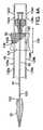
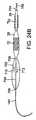
図1は、一実施形態による、人工心臓弁12(例えば、人工大動脈弁)を心臓へ送達するように適合される送達装置10を示す。装置10は、概して、操縦可能なガイドカテーテル14(フレックスカテーテルとも称される)と、ガイドカテーテル14を通って延びるバルーンカテーテル16と、バルーンカテーテル16を通って延びるノーズカテーテル18とを含む。図示された実施形態におけるガイドカテーテル14、バルーンカテーテル16、およびノーズカテーテル18は、以下で詳細に説明するように、患者の体内の植え込み部位への弁12の送達および位置決めを容易にするために、互いに対して縦方向に摺動するように適合される。 FIG. 1 shows a
ガイドカテーテル14は、ハンドル部分20と、ハンドル部分20から延びる細長いガイドチューブ、またはシャフト22とを含む。バルーンカテーテル16は、ハンドル部分20に隣接する近位部分24と、近位部分24からハンドル部分20およびガイドチューブ22を通って延びる細長いシャフト26とを含む。膨張可能なバルーン28は、バルーンカテーテルの遠位端に装着される。弁12は、患者の血管系を通って心臓へ送達するために小さくされた直径を有する縮んだ状態で、バルーン28に装着されて示されている。 The
ノーズカテーテル18は、バルーンカテーテルの近位部分24、シャフト26、およびバルーン28を通って延びる細長いシャフト30を含む。ノーズカテーテル18は、シャフト30の遠位端に装着され、患者の血管系を通って植え込み部位に弁を前進させるために装置10が使用される場合、バルーンの遠位端部分を受けるように適合される、ノーズピース32をさらに含む。 The
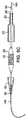
図2Aおよび2Bに見られるように、図示された構成内のバルーンカテーテル16は、近位部分24から外部シャフト26およびバルーン28を通って同軸上に延びる内部シャフト34(図2B)をさらに含む。バルーン28は、外部シャフト26から外向きに延びる内部シャフト34の遠位端部分上に支持され得、バルーンの近位端部分36は、外部シャフト26の遠位端に取り付けられる(例えば、適切な接着剤によって)。内部シャフト34の外径は、外部シャフトの全長に沿って、内部シャフトと外部シャフトとの間に環状空間が画定されるようにサイズ決定される。バルーンカテーテルの近位部分24は、バルーンを膨張させるために流体源(例えば、水源)と流体接続可能な流体通路38を有するように形成され得る。流体通路38は、バルーンを膨張させて弁12を設置するために、流体源からの流体が流体通路38、シャフト間の空間を通ってバルーン28内に流れることができるように、内部シャフト34と外部シャフト26との間にある環状空間と流体連通している。 As seen in FIGS. 2A and 2B, the
近位部分24は、内部シャフト34の管腔42と連通している内部管腔40も画定する。図示された実施形態内の管腔40、42は、ノーズカテーテルのシャフト30を受けるようにサイズ決定される。バルーンカテーテル16は、近位部分24に接続された連結器44と、当該連結器から延びるチューブ46とを含んでもよい。チューブ46は、管腔40と流体連通する内部通路を画定する。バルーンカテーテル16は、連結器44の近位端に接続された摺動支持部48を含んでもよい。摺動支持部48は、以下でさらに詳細に説明するように、バルーンカテーテル16に対して選択された縦方向位置にノーズカテーテルが維持されることを可能にするために、ノーズカテーテル18の調整リング50(図1および4A〜4B)を支持し、それと協働する。
図2Aに示すように、外部シャフト26の外面は、シャフト26の近位端部分に沿って、互いに離間した1つ以上の環状溝またはノッチ52a、52b、52cを含み得る。以下でさらに詳細に説明するように、溝は、ガイドカテーテル14(図3A〜3B)の係止機構84と協働して、ガイドカテーテル14がバルーンカテーテル16に対して選択された縦方向位置に維持されることを可能にする。 As shown in FIG. 2A, the outer surface of the
バルーンカテーテルの内部シャフト34および外部シャフト26は、ナイロン、編組ステンレス鋼ワイヤ、またはポリエーテルブロックアミド(Pebax(登録商標)として市販されている)等、種々の適切な材料のうちのいずれかから形成され得る。シャフト26、34は、それらの長さに沿って、シャフトの可撓性を変動させるために、異なる材料から形成された縦方向区間を有し得る。内部シャフト34は、ノーズカテーテルシャフト30との摺動摩擦を最小化するために、Teflon(登録商標)で形成された内部ライナーまたは層を有し得る。 Balloon catheter
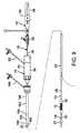
図3Aおよび3Bにおいて、ガイドカテーテル14をさらに詳細に示す。上述のように、ガイドカテーテル14は、ハンドル部分20と、そこから遠位に延びる細長いガイドチューブまたはシャフト22とを含む。ガイドチューブ22は、バルーンカテーテルの外部シャフト26を受け、バルーンカテーテルがガイドカテーテルに対して縦方向に摺動することを可能にするようにサイズ決定された管腔54を画定する。ガイドチューブ22の遠位端部分は、操縦可能区間56を備え、その曲率は、患者の血管系、特に大動脈弓を通って装置を案内するのを補助するために、オペレータによって調整され得る。 3A and 3B, the
ガイドカテーテルは、望ましくは、ガイドチューブ22の遠位端に取り付けられたカバーまたはシュラウド23を含む。特定の実施形態におけるカバー23は、バルーンの周囲で縮んだ弁12を受けて、バルーン28の遠位端部分を覆うように適合されるノーズピース32の近位端面と密接するように(図8Aに示すように)、サイズ決定および成形される。したがって、装置を設置部位まで前進させると、弁12およびバルーン28は、カバー23およびノーズピース32内に完全に包囲され得る。 The guide catheter desirably includes a cover or
図3Aおよび3Bにおいてさらに示すように、ハンドル部分20は、ガイドチューブ22の近位端部分を受ける中心管腔60を有するように形成された本体、つまりハウジング58を含む。ハンドル部分20は、管腔60と流体連通する内部通路を画定するサイドアーム62を含んでもよい。サイドアーム62の上端に止コック63を装着してもよい。 As further shown in FIGS. 3A and 3B, the
ハンドル部分20は、操縦可能区間56と動作可能に接続され、ハンドル部分の手動調整による、操縦可能区間56の曲率のオペレータ調整を可能にするための調整として機能する。図示された実施形態において、例えば、ハンドル部分20は、ハンドル本体58内部にあるガイドチューブ22の一部を取り囲む内部スリーブ64を含む。ネジ式摺動ナット68がスリーブ64上に配置され、それに対して摺動可能である。摺動ナット68は、調整つまみ70の雌ネジと嵌合する雄ネジを有するように形成される。 The
図5Aおよび5Bに最もよく示すように、摺動ナット68は、当該ナットの内面上に形成され、その長さだけ延びる、2つのスロット76を有するように形成される。図6Aおよび6Bに最もよく示すように、スリーブ64は、摺動ナットがスリーブ上に載置された際に摺動ナット68のスロット76と並置される、縦方向に延びるスロット78を有するようにも形成される。各スロット78内に配置されるのは、各細長いナットガイド66a、66b(図3B)であり、これらは、細長い棒またはピンの形態であってもよい。ナットガイド66a、66bは、スリーブ64に対する摺動ナット68の回転を防止するために、摺動ナット68内にある各スロット76内へ半径方向に延びる。この配列により、調整つまみ70の回転(時計回りまたは反時計回り)は、摺動ナット68を、双頭矢印72で示される方向へ、スリーブ64に対して縦方向に移動させる。 As best shown in FIGS. 5A and 5B, the sliding
1本以上の牽引ワイヤ74は、調整つまみの回転時に操縦可能区間の運動を生み出すために、調整つまみ70を操縦可能区間56に接続する。いくつかの実施形態において、牽引ワイヤ74の近位端部分は、ピン80を当該牽引ワイヤに対し押し付ける等によって抜け止めピン80(図3A)内へ延び、それに取り付けられることができる。ピン80は、(図5Aに最もよく示すように)摺動ナット68内にあるスロット82内に配置される。牽引ワイヤ74は、ピン80から、摺動ナット内のスロット98、スリーブ64内のスロット100を通って延び、シャフト22(図3A)内の牽引ワイヤ管腔に入り、それを通る。牽引ワイヤ74の遠位端部分は、操縦可能区間56の遠位端部分に取り付けられる。 One or
牽引ワイヤ74の近位端を保持するピン80は、摺動ナット68内にあるスロット82内に捕捉される。したがって、調整つまみ70を回転させて摺動ナット68を近位方向に(バルーンカテーテルの近位部分24の方へ)移動させると、牽引ワイヤ74も近位方向に移動する。牽引ワイヤは、操縦可能区間56の遠位端をハンドル部分の方へ戻すように牽引し、それによって操縦可能区間を屈曲させ、その曲率半径を減少させる。調整つまみ70と摺動ナット68との間の摩擦は、牽引ワイヤの緊張を持続するために十分なものであり、それにより、オペレータが調整つまみ70を手放した場合に、操縦可能区間内の曲り部の形状を保存する。摺動ナット68を遠位方向に移動させるために調整つまみ70を反対方向に回転させると、牽引ワイヤの張力は解放される。操縦可能区間56の弾力性は、牽引ワイヤにかかっている張力が減少した際に、当該操縦可能区間をその正常な撓まされていない形状に戻す。牽引ワイヤ74は摺動ナット68に固定されていないため、当該摺動ナットの遠位方向への運動は、牽引ワイヤの端部を押圧するものではなく、牽引ワイヤを座屈させるものである。代わりに、牽引ワイヤの張力を減少させるようにつまみ70が調整される際に、摺動ナット68のスロット82内にピン80を浮遊させることができ、それによって牽引ワイヤが座屈するのを防止する。 A
特定の実施形態において、その撓まされていない形状における操縦可能区間56はわずかに湾曲しており、その完全に湾曲した位置において、操縦可能区間は大動脈弓の形状と略一致する。その他の実施形態において、操縦可能区間は、その撓まされていない位置で実質的に直線状である場合がある。 In certain embodiments, the
ハンドル部分20は、バルーンカテーテル16を、ガイドカテーテル14に対して選択された縦方向位置に保持するように構成される係止機構84を含んでもよい。図示された構成内の係止機構84は、それを通ってバルーンカテーテルの外部シャフト26が延びる開口88を有する押しボタン86を備える。図3Aに最もよく示すように、ボタン86は、部分的に内部スロット92内に受けられる遠位端部分90を有する。スロット92内に配置されたコイルばね94は、遠位端部分90を支承し、シャフト26の方へ弾性的に付勢する。遠位端部分90は、シャフト26(図2A)上の溝52a、52b、52cのいずれか内に入れ子になることができる小突起96を有するように形成されてもよい。溝のうちの1つが突起96と並置される場合、シャフト26をガイドカテーテルに対して縦方向位置に保持するために(図3Aに描写するように)、ばね94は当該突起を溝内へ付勢する。図示された実施形態内の溝は、シャフト26の周囲において円周方向に完全に延びるため、バルーンカテーテルの縦方向位置がボタン86によって適所に係止された場合、バルーンカテーテルをガイドカテーテルに対して回転させることができる。バルーンカテーテルの位置は、シャフト26の対応する溝から突起96を除去するために、ボタン86をばね94の付勢に対して内向きに押下することによって解放され得る。 The
ハンドル部分20は、操縦可能区間56の曲率を調整するように適合されるその他の構成を有してもよい。そのような1つの代替的なハンドル構成は、同時係属の米国特許出願第11/152,288号(第US2007/0005131号公報として公開)において示されており、当該出願は参照することにより本願に組み込まれる。ハンドル部分の別の実施形態については、以下で説明し、図11〜15に示す。 The
図7Aおよび7Bは、1つの特定の実施形態にしたがって構築されたガイドカテーテルシャフト22を示す。図示された実施形態内のシャフト22は、PTFE等の低摩擦ポリマー材料で作製された管状内部ライナー104を備える。ライナー104は、それを通して収縮したバルーン28およびバルーンカテーテルシャフト26を挿入できるようにサイズ決定される。内部ライナー104の外側に沿って延びる、より小径の導管、つまりライナー106は、それを通って牽引ワイヤ74が延びる管腔を画定する。外層108はライナー104、106を取り囲み、シャフト22に所望の可撓性および剛性を与える。 7A and 7B illustrate a
図示された実施形態内の外層108は、ライナー104および導管106の周囲に巻かれた編組金属ワイヤ110から形成される編組層と、当該編組金属ワイヤ層を取り囲み、封入するポリマー材料112とを備える。特定の実施形態において、シャフトは、ライナー104、106を形成し、それらのライナーを互いに対して平行関係に並べて載置し、それらのライナーの周囲に金属ワイヤを巻き付けて編組層を形成し、当該編組層上にポリマースリーブを載置し、当該スリーブをリフローしてライナーを取り囲む均一な積層108を形成することによって形成され得る。いくつかの実施形態において、ポリマー材料112は任意の適切な材料を含むが、望ましくは、Pebax(登録商標)等の熱可塑性エラストマーを含む。編組金属層は、ステンレス鋼ワイヤから構築されてもよい。 The
図7Aにおいて最もよく示すように、シャフト22は、望ましくは、当該シャフトの近位端116から操縦可能区間56の近位端118へ延びる比較的堅い区間114を備える。特定の実施形態において、操縦可能区間56の長さは、シャフト22の全長の約1/4を含む。実用的な実施形態において、シャフト22の全長は約45インチ(操縦可能区間を含む)であり、操縦可能区間の長さは約11.7インチであるが、シャフトの全長および/または操縦可能区間の長さは、特定の用途に応じて変動し得る。 As best shown in FIG. 7A, the
シャフトの操縦可能区間56は、上述のように調整つまみ70の調整時に操縦可能区間が曲がるように、望ましくは比較的軟らかいデュロメータ材料112から形成される。堅い区間114は、望ましくは、調整つまみ70によって牽引ワイヤに張力がかけられた際に曲げに耐える、比較的堅いポリマー材料112から形成される。堅い区間114は、望ましくは、オペレータが装置10を押圧して収縮している可能性がある脈管を通過させることを可能にするのに十分な硬さを呈する。特定の実施形態において、操縦可能区間のポリマー材料112は55D Pebax(登録商標)を含み、シャフトの残余区間114のポリマー材料112は、55D Pebax(登録商標)よりも堅い72D Pebax(登録商標)を含む。 The
代替的な実施形態において、操縦可能区間56内の金属編組層は、操縦可能区間の可撓性を強化するために内部ライナー104上に配置された金属コイル(例えば、ステンレス鋼コイル)と置換され得る。したがって、この代替的な実施形態において、編組金属層は堅い区間114に沿って延び、金属コイルは操縦可能区間56に沿って延びる。別の実施形態において、操縦可能区間56内の金属編組層は、同時係属の米国特許出願第11/152,288号において開示されているような、レーザ切断され、円周方向に延びる開口部を有するように形成されたステンレス鋼ハイポチューブと置換され得る。 In an alternative embodiment, the metal braid layer in the
図7Cに示すように、シャフト22の遠位端は、張り出しまたは拡大端部分116を含んでもよい。端部分116の外径Dは、バルーン28上に支持される縮んだ弁12の外径と等しいか、またはほぼ同じである。したがって、弁12が導入用シースを通って前進すると、端部分116は、バルーン28ではなく縮んだ弁12を押圧する。これは、バルーンカテーテルと弁との間の不用意な運動を最小化し、バルーン上における弁の位置を移動させることができる。特定の実施形態において、シャフト22は約16Fから約18Fの外径を有し、端部分116は約22Fの外径Dを有する。拡大された端部分116は、種々の適切な材料のいずれで作製されてもよい。例えば、端部分116は、Pebax(登録商標)(例えば、55D Pebax(登録商標))から鋳造され、操縦可能区間56の端部分においてリフローされてもよい。 As shown in FIG. 7C, the distal end of the
上述のように、牽引ワイヤ74の遠位端は、操縦可能区間56の遠位端に取り付けられる。図7Cに最もよく示すように、これは、牽引ワイヤ74の遠位端部分を、シャフトの外層108に埋め込まれた金属リング118に取り付けること、例えば牽引ワイヤを金属リングに溶接すること等によって実現され得る。 As described above, the distal end of
図7A〜7Cには示されていないが、ガイドカテーテルシャフト22は、弁の送達中に弁12およびバルーン28(またはその一部)を覆うためのカバー23を含んでもよい。以下で説明するように、導入用シースの使用は、患者の血管系への挿入時に弁が覆われる場合には任意となり得る。 Although not shown in FIGS. 7A-7C, the
図4Aおよび4Bを参照すると、上記で簡単に述べたように、ノーズカテーテル18は、その近位端に調整リング50、その遠位端にノーズピース32を、また、それらの間に延びる細長いシャフト30を含む。シャフト30は、望ましくは、装置10が体内の送達経路に挿入された後、ガイドワイヤ上を前進できるよう、ガイドワイヤ140(図8A)を受けるための、シャフトの長さだけ延びる管腔120を有するように形成される。図4Aおよび4Bに示すように、ノーズピース32は、望ましくは、バルーン28の少なくとも遠位端部分を受けるようにサイズ決定および成形された開口部またはキャビティ122を有するように形成される。 4A and 4B, as briefly described above, the
図4Aに最もよく示すように、調整リング50は、バルーンカテーテルの摺動支持部48上に配置され、それに対して摺動可能であり、ノーズカテーテルをバルーンカテーテルに対して選択的な縦方向位置に保持するための係止または保持機構として機能する。さらに説明すると、シャフト30は、摺動支持部48内に配置されたシャフト支持部124を通って延び、それに固定して取り付けられる。調整リング50は、摺動支持部48内の細長いスロット128a、128bを通って延びるネジ126によってシャフト支持部124に取り付けられる。スロット128a、128bは、摺動支持部48の長さに沿って縦方向に延びる。したがって、調整リング50が摺動支持部48の長さに沿って縦方向に(双頭矢印130で示す方向に)摺動されると、バルーンカテーテルに対するノーズカテーテルの縦方向位置を調整するように、シャフト支持部124およびシャフト30も同じ方向に移動させられる。 As best shown in FIG. 4A, the
スロット128aは円周方向に延びるノッチ132a〜132dを有するように形成され、スロット128bは、ノッチ132a〜132dの反対側に、円周方向に延びる同様のノッチ134a〜134dを有するように形成される。したがって、各ノッチ132a〜132dについて、スロット128bから延びる、対応する正反対のノッチ134a〜134dがある。バルーンカテーテルに対するノーズカテーテルの縦方向位置を保持するために、ネジ126を一対の正反対のノッチと並置させるように調整リング50を移動させ、わずかに回転させてネジ126をノッチ内に位置付ける。例えば、図4は、ノッチ132bおよび134b内に位置付けられたネジ126を示す。ノッチはネジ126の、したがってシャフト支持部124およびシャフト30の、遠位および近位方向への運動を制限する。 The
図示された実施形態において、各スロット128a、128bは、4つのノッチを有するように形成されている。ネジ126がノッチ132c、134c内またはノッチ132d、134d内に位置付けられている場合、ノーズピース32は、バルーン28および弁12がカバー23およびノーズピース32によって完全に包囲されるように、バルーン28の遠位端部分を覆い、ガイドカテーテル14のカバー23に隣接する位置に保持される(図8A)。ネジ126がノッチ132b、134b内に位置付けられている場合、ノーズピース32は、バルーンを膨張させることによってノーズピースからの干渉を受けることなく弁を設置できるように、バルーン28から第1の距離だけ遠位に離間した位置に保持される(図8C)。ネジがノッチ132a、134a内に位置付けられている場合、ノーズピースは、バルーン28から、第1の距離よりも大きい第2の距離だけ遠位に離間した位置に保持される。この位置において、バルーン28は、ノーズピースからの干渉を受けることなく、(弁設置後に)カバー23の内側に再び折り畳まれ得る。 In the illustrated embodiment, each
弁12は、多種多様な異なる形態をとり得る。特定の実施形態において、弁は、概して、弁構造を支持する拡張可能なステント部分を備える。ステント部分は、望ましくは、弁を治療部位に保留し、狭窄した自然弁の弁尖の反動に耐えるのに十分な半径方向の強度を有する。バルーン拡張可能弁の実施形態に関するさらなる詳細は、それぞれ「IMPLANTABLE PROSTHETIC VALVE」と題された米国特許第6,730,118号および第6,893,460号において見られ、これらの特許は参照することにより本願に組み込まれる。送達システムを自己拡張式人工弁と共に使用してもよいことも十分に理解されるであろう。例えば、自己拡張式弁を使用する場合、弁をその圧迫状態に維持する送達スリーブから自己拡張式弁を取り出すのを補助するために、押圧器具を使用してもよい。 The
自然大動脈弁(または、以前に植え込まれ、機能が衰えてきた人工大動脈弁)と交換するために弁12を使用する場合、縮んだ状態でバルーン装着された弁が、大腿動脈を通って体内に導入され、大動脈弓を通って心臓まで前進させられる、逆行性アプローチで弁12を植え込むことができる。使用中、患者の血管系を通って送達デバイス10を前進させるのを補助するために、ガイドワイヤ140(図8A)を使用してもよい。ガイドワイヤ140は、送達デバイスを導入するために脈管の内径を拡張させる拡張器(図示せず)によって、脈管内に載置されることができる。拡張器直径は、例えば12乃至22フレンチの範囲である。 When using the
上述し図8Aに示すように、弁12はカバー23内に位置付けられることができ、このときノーズピース32は、バルーン28の遠位端を覆い、カバー23の遠位端に隣接する。ノーズカテーテルの調整リング50は、送達中、カバー23に対してノーズピース32を保持するために適所に係止され得る。この位置において、ノーズカテーテルは、望ましくは、血管系を通るデバイスをトラッキングする間および体内からの送達装置の除去中に、ノーズピースがカバーから分離するのを抑制するために、ノーズピース32をカバー32に対してしっかりと保留することでわずかな張力をかけて載置される。 As described above and shown in FIG. 8A, the
有利なことに、図示された実施形態内の弁12はカバー23によって完全に覆われることができるため、脈管内に弁を導入するために導入用シースを必要としない。逆行性手順においては、一般に約22〜24フレンチの直径を有する導入用シースが使用される。対照的に、カバー23は、望ましくは、導入用シースの外径に満たない外径を有し、特定の実施形態において、カバー23の外径は、約0.260インチから約0.360インチの範囲であり、約0.330インチは特定の例である。デバイスの全径を縮小することにより、大腿動脈に対する閉塞性が低くなり、当該手順中、患者の脚部は十分に灌流されたままの状態であることができる。さらに、送達デバイスの最大直径を表すカバー23は、大腿動脈および腸骨動脈と極めて短時間のみ接触していればよいため、これらの血管への外傷が最小化され得る。 Advantageously, since the
あまり望ましくはないが、その他の実施形態において、カバー23は、送達中、弁およびバルーンの外面がカバー23によって覆われる部分が少なくなるように、さらに短い長さであってもよい。例えば、カバー23は、バルーンの近位端部分または弁の近位端部分のみの上に延びるように寸法決定されてもよい。 Although less desirable, in other embodiments, the
ガイドワイヤ140上で大動脈弓を通って送達装置10を前進させる際、ガイドカテーテル14は、大動脈の内面から離れて装置を「操縦する」ために使用される。ノーズピース32のテーパー状の遠位端部分は、大腿動脈および腸骨動脈を通るトラッキングを補助し、その上、大動脈弓を通る非侵襲的トラッキングおよび自然大動脈弁の円滑な横断を提供する。従来技術の送達システムでは、バルーンカテーテルの遠位端にノーズピースを固定することが公知であり、これにより、ガイドカテーテルの操作によって湾曲させることができないデバイスの部分の長さを増大させる。対照的に、図示された実施形態内のノーズピース32は、弁12に対して移動され得る別個のノーズカテーテル18に装着されている。したがって、送達デバイスの遠位端にある操縦不可能な区間の長さを最小化するために、送達中、バルーンの遠位端部分上にノーズピース32を装着してもよい。これは、送達デバイスの端部と大動脈の内壁との間の接触が殆どまたは全くないように、大動脈弓を通る、より容易なトラッキングを可能にするものである。特定の実施形態において、送達デバイスの端部にある操縦不可能な区間の長さL(図8A)は、約6cm以下である。 In advancing the
弁を植え込み部位に位置付けるために、オペレータは、従来の蛍光透視法を使用して、ガイドワイヤシャフト34上のマーカーバンド142(図2Aおよび2B)の位置をトラッキングすることができる。弁12が大動脈弁輪内まで前進した後、ノーズカテーテルは、バルーン28から遠位に離れてノーズピース32を前進させるためにバルーンカテーテルに対して遠位に移動されることができ(図8B)、ガイドカテーテルは、カバー23から弁12を露出させるためにバルーンカテーテルに対して近位に移動されることができる(図8C)。上記で説明したように、ノーズカテーテルおよびガイドカテーテルの縦方向位置は、オペレータが弁12の位置を調整し、その後それを設置する間に、バルーンカテーテルに対して固定され得る。バルーン28の膨張は、弁12を拡張して自然弁の弁尖と係合させるために効果的である。続いて、バルーン28を収縮させてカバー23内へ退避させることができ、ノーズピース32は、バルーンの遠位端部分の上へ引き戻されることができる。続いて、送達装置全体をガイドワイヤ140上で引き抜いて本体から除去することができ、その後、ガイドワイヤを本体から除去することができる。 To position the valve at the implantation site, the operator can track the position of the marker band 142 (FIGS. 2A and 2B) on the
図9は、送達装置10の代替的な実施形態を示す。本実施形態において、ガイドカテーテル14にはカバー23(図3Aおよび3Bにおいて先に図示したようなもの)が設けられず、代わりに、送達装置を体内へ導入するために導入用シース150が使用され得る。図10Aおよび10Bに最もよく示すように、図示された実施形態内の導入用シース150は、導入用ハウジング152と、ハウジング152から延びる導入用スリーブ154とを含む。ハウジング152は、シール弁166を格納する。使用中、スリーブ154は脈管(例えば、大腿動脈)内へ挿入され、一方、ハウジング152は体外に残存する。送達装置10は、ハウジング内の近位開口部168、シール弁166、スリーブ154を通って脈管内へ挿入される。シール弁166は、失血を最小化するために、ガイドカテーテルシャフト22の外面とシール係合する。いくつかの実施形態において、スリーブ154は、親水性皮膜で被覆されてもよく、脈管内へ約9インチ延び、腸骨分岐部を少し過ぎた、患者の腹部大動脈内へ入る。 FIG. 9 shows an alternative embodiment of the
スリーブ154は、近位端158における第1の直径から遠位端160における第2の、より小さい直径へ先細になる、テーパー状区間156を有してもよい。小径遠位端部分162は、テーパー状部分156からスリーブ154の遠位端まで延びる。テーパー状部分156は、スリーブ154の外面とガイドカテーテル14のガイドシャフト22の外面との間の、より円滑な遷移を提供する。テーパー状部分156は、大腿動脈の完全閉塞を最小化することを支援するために、患者の血管系内におけるスリーブ154の可変載置も可能にする。 The
図11〜15は、ハンドル部分20の代わりにガイドカテーテル14(図1および3A)において使用され得る、200で示されるハンドル部分の、代替的な実施形態を示す。図示された実施形態内のハンドル部分200は、主ハウジング202と、ハウジング202と旋回可能に接続された調整レバー204とを含む。レバー204は、以下でさらに説明するように、シャフト22の曲率を調整するために遠位および近位に(図13の双頭矢印206で示すように)旋回され得る。 FIGS. 11-15 illustrate an alternative embodiment of a handle portion, indicated at 200, that may be used in the guide catheter 14 (FIGS. 1 and 3A) instead of the
図14に最もよく示すように、ハウジング202は、適切な接着剤、機械的留め具、スナップ式接続部、またはその他の適切な技術を使用して互いに取り付けられ得る、第1および第2のハウジング部分208、210から形成され得る。ハウジング202内に配置されるのは、それを通って延びる中心孔226を有するシールハウジング212である。孔226の遠位端部分は、シャフト22の近位端部分214を受ける拡大部分を形成することができる。シャフト22は、シールハウジング212から主ハウジング202を通って延び、本体202の遠位端に接続されたノーズピース228から出る。末端部216は、これらの2つのコンポーネント間に捕捉されたシール218を有するシールハウジング212の近位端に接続され得る。図15に最もよく示すように、末端部216は、シール218およびシールハウジング212の端部分を受けるように成形された段付き孔を有するように形成されてもよい。シール218は、シリコン等の適切なエラストマーから作製され得る。バルーンカテーテル16のシャフト26は、末端部216、シール218内の中央開口部、シールハウジング212、およびガイドカテーテルシャフト22を通って延びる。シールハウジング212は、中心孔226と流体連通しているフラッシュポート220を有するように形成されてもよい。フラッシュポート220は、可撓性チューブ222の一端を受ける。チューブ222の反対端は、止コック224に接続され得る(図11)。 As best shown in FIG. 14, the
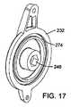
図14に示すように、図示された構成内のレバー204は、それぞれ主ハウジング202の両側面に装着された第1および第2のレバー部分230、232を含む。各レバー部分の内面は、各Oリング234を受けるように適合される環状溝274を有するように形成されてもよい。レバー部分230は、レバー部分の旋回運動時に滑車の回転を生み出すように、ハウジング内に装着された滑車236と連結されてもよい。例えば、レバー部分230は、滑車236内に、ハウジング部分208を通って相補的形状の陥凹部240内へ延びる突起238(図16A)を有するように形成されてもよい。突起236は、レバーが始動した際に滑車の回転を生み出すために、その外面上に、陥凹部240内の対応する平坦部と係合する平坦部を有するように形成されてもよい。滑車236は、シャフト244の一方の端部分を受けるように成形された非円形陥凹部または開口部242を有するように形成されてもよい(図14)。シャフト244の反対端は、第2のハウジング部分210を通り、レバー部分232の相補的形状の陥凹部または開口部246内へ延びる(図17)。図示された構成において、シャフト244の端部分ならびに対応する開口部242および246は、シャフト244と、滑車236と、レバー部分232との間の相対的回転を抑制するために六角形であるが、その他種々の非円形形状を使用してもよい。あるいは、別の方法で、シャフトが滑車およびレバー部分に対する回転に対して固定されている場合、シャフトの端部分および開口部242、246は円形であってもよい。 As shown in FIG. 14, the
上下のクロスバー248、250は、第1および第2のレバー部分230、232の各上下の耳部間にそれぞれ接続され、延びる。レバー部分230、232の耳部を通って延び、クロスバー248、250に螺着されるネジ252は、レバー204のコンポーネントを本体202に取り付けるために使用され得る。ネジ254は、レバー部分230、ハウジング部分208を通り、シャフト244内のネジ付き開口部内へ延び、得る。調整つまみ266をネジ268に固定して取り付けてもよく、これはレバー部分232、ハウジング部分210を通り、シャフト244の反対端にあるネジ付き開口部内へ延び、得る。ネジ268は、例えば調整つまみの内面上にある陥凹部(図示せず)内にネジ頭を接着取り付けすることにより、調整つまみに固定して取り付けられてもよい。その結果、滑車236の回転摩擦を調整するために、調整つまみ266を手動で回転させて、ネジを緩めるか、または締めてシャフト244に螺入させることができる。 The upper and lower cross bars 248, 250 are connected and extend between the upper and lower ears of the first and
再度図15を参照すると、牽引ワイヤ74は、シャフト22内の牽引ワイヤ管腔を通って延び、主ハウジング202の内側のシャフトから延びる。糸等の可撓性引っ張り部材256が、その一端において牽引ワイヤ74の端部に結紮されるか、または他の方式で接続される。引っ張り部材256は、横材258の周囲、部分的に滑車236の外周の周囲を、滑車内の半径方向に延びる開口部260を通って延び、滑車236の中心に隣接するシャフト244に結紮されるか、または他の方式で接続される。図16Aおよび16Bに示すように、滑車236は、引っ張り部材256を受けるように適合される環状溝または陥凹部262を有するように形成されてもよい。 Referring again to FIG. 15, the
ハンドル部分200の動作を説明すると、図18Aは、最前位置における調整レバー204を示す。この位置において、シャフト22の操縦可能区間56は、その正常な撓まされていない状態にある(例えば、図1に示すように直線状、またはわずかに湾曲している)。レバー204を後方へ、つまり矢印264の方向に旋回させると、図示された実施形態において滑車236は時計回りに回転し、引っ張り部材を滑車の周囲に巻き、牽引ワイヤ74を後方へ牽引する。続いて、牽引ワイヤ74は、先に記載した方式で、操縦可能区間56の曲率を調整するように、シャフトの遠位端上で牽引する。図18Bは、シャフト22の操縦可能区間の完全に湾曲した位置に対応する最後位置におけるレバー204を示す。 Describing the operation of the
滑車236の回転摩擦は牽引ワイヤの緊張を持続するために十分なものであり、それにより、オペレータが調整レバー204を手放した場合に、操縦可能区間内の曲り部の形状を保存する。レバー204が最前位置の方へ戻るように旋回されると(図18A)、牽引ワイヤの張力が解放される。操縦可能区間56の弾力性は、牽引ワイヤにかかっている張力が減少した際に、当該操縦可能区間をその正常な撓まされていない形状に戻す。図示された実施形態内の引っ張り部材256は牽引ワイヤに押圧力を印加しないため、レバー204の最前位置の方への運動は、牽引ワイヤの座屈を引き起こさない。さらに、前述のように、調整つまみ266は、滑車236の回転摩擦を変動させるために、オペレータによって調整され得る。回転摩擦は、望ましくは、ガイドカテーテルが患者の血管系内にある間に不注意に引き戻されても、血管系を通って牽引される際に操縦可能区間を直線状に伸ばし、血管系の壁への外傷を最小限にするように、牽引ワイヤの前方牽引力(図18Bにおいて矢印270で示す)下において、滑車が最前位置の方へ回転することができるように調整される。 The rotational friction of the
有利なことに、図示された実施形態内の調整レバー204は、当該レバーの運動を受けて操縦可能区間の実質的に1:1の撓みを提供し、すなわち、レバー204の回転は、牽引ワイヤ、したがって操縦可能区間56の実質的に1:1の運動を引き起こす。このようにして、調整レバー204は、血管系を通るトラッキングを容易にするために、操縦可能区間の曲率に関する触覚フィードバックをオペレータに提供する。また、レバーは、使用中におけるガイドカテーテルの適切な配向を維持するために、人間工学的に位置付けられる。図示されたハンドル部分200のもう1つの利点は、バルーンカテーテル16(図2B)の近位部分24またはその一部が末端部216内に着座して、バルーンカテーテルの作業長さを最小化できることである。 Advantageously, the
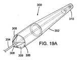
図19Aおよび19Bは、一実施形態による、ノーズカテーテル18の代わりに送達装置10(図1)と共に使用され得る代替的なノーズカテーテル300を示す。図示された構成内のノーズカテーテル300は、ノーズカテーテルシャフト304に接続されたノーズピースまたは弁カバー302を含む。弁カバー302は、バルーン28と、当該バルーンに装着された弁12とを覆うように適合される。したがって、本実施形態において、ガイドカテーテル14は、送達中に弁を覆うためにカバー23(図8A)を有さなくてもよい。シャフト304は、その遠位端においてカバー302の遠位端に固定して取り付けられ、バルーン28およびバルーンカテーテルシャフト26を通って延びる。シャフト304は、ガイドワイヤ140を受けるために管腔を有してもよい。シャフト304は、先に説明したノーズカテーテル18のように、バルーンカテーテルおよびガイドカテーテルに対して縦方向に移動することができる。 19A and 19B illustrate an
図19Aに最もよく示すように、カバー302は、三角皮弁308を画定する複数のスリットを有するように形成された近位端部分306を有する。皮弁308は、弁を設置することが望ましい場合、互いから半径方向に外向きに曲がり、バルーン28および弁12の通過を可能にするために十分大きい開口部を形成することができる。近位端部分306は、導入用シースへ戻るカバー302の退避を容易にするために、図示するように先細になってもよい。端部分306のテーパー形状は、送達装置が体内から引き抜かれる際の血管系の壁への外傷を最小化するために、非侵襲的表面も提供する。カバーは、大腿動脈および腸骨動脈を通るトラッキングを補助し、その上、大動脈弓を通る非侵襲
的トラッキングおよび自然大動脈弁の円滑な横断を提供するために、テーパー状の遠位端部分310を有してもよい。As best shown in FIG. 19A, the
カバー302は、望ましくは、ナイロン、Pebax(登録商標)、またはPET等の可撓性材料から作製され、約0.0015インチから約0.015インチの範囲の壁厚を有し得る。カバー302を十分可撓性にすることにより、患者の血管系を通って前進する送達装置の部分に沿った比較的堅く、非可撓性の区間だけが、弁によって覆われるバルーンの区間となる。これにより、ガイドワイヤ140が蛇行性の脈管を通って前進する際にその経路をたどる、送達装置の能力を大幅に強化する。 Cover 302 is desirably made from a flexible material such as nylon, Pebax®, or PET, and may have a wall thickness in the range of about 0.0015 inches to about 0.015 inches. By making the
使用中、送達装置は、弁が設置場所またはその付近に位置付けられるまで、ガイドワイヤ140上を前進させられる。次いで、図19Cに示すように、バルーンおよび弁12のカバーを取り外すために、ノーズカテーテル300をバルーンカテーテル16に対して遠位に前進させる。カバー302を遠位に前進させると、バルーンおよび弁は、皮弁308によって形成された近位開口部を通過することができる。弁12が露出されると、バルーン28を膨張させて当該弁を設置することができる。 In use, the delivery device is advanced over the
図20Aは、弁カバー23を、ガイドカテーテルシャフト22の遠位端に接続された拡張可能なメッシュバスケットまたはカバー400と置換した、ガイドカテーテル14の修正形態を示す。カバー400は、弁12およびバルーン28を覆うようにサイズ決定および成形されている。したがって、本実施形態においては、ノーズカテーテル(例えば、ノーズカテーテル18)を使用する必要がない。カバー400は、金属ワイヤ(例えば、ニチノールまたはステンレス鋼ワイヤ)から形成された編組メッシュ構成を有してもよい。 FIG. 20A shows a modified
1本以上のリボンワイヤ402がカバー400の遠位端404に接続され、ガイドカテーテルシャフト22内の各管腔を通り、その長さに沿って延びる(図20B)。ワイヤ402は、例えば、0.003インチ×0.020インチのニチノールリボンワイヤであってもよい。ワイヤ402は、それらの近位端において、オペレータがワイヤに押圧力または牽引力を印加することを可能にするガイドカテーテルのハンドル部分に接続される。ワイヤ402を前方、つまり矢印406の方向へ押圧することにより、バルーン28および弁12上でカバーを崩れさせ、円滑なトラッキング外形を提供する。ワイヤ402を後方、つまり矢印408の方向へ牽引することにより、カバーを拡張させて、バルーンおよび弁が、カバー400の遠位端404にある開口部を通って外向きに前進することを可能にする。 One or
使用中、カバー400は、患者の血管系を通って設置部位へ送達するために、弁およびバルーンを覆う崩れた状態で載置される。続いて、ワイヤ402は、カバー400を拡張するために、近位方向(矢印408によって示す)に牽引される。続いて、ガイドカテーテルは、バルーンおよび弁をカバーの遠位端から前進させるように、近位方向に牽引され得る。あるいは、バルーンおよび弁をカバー400から前進させるために、バルーンカテーテル16をガイドカテーテル14に対して遠位に前進させてもよい。 In use, the
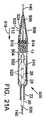
図21A〜21Cは、500で示す送達装置の代替的な実施形態を示す。送達装置500は、脈管内側のバルーンカテーテルのバルーン28に弁12を装着することを可能にする。バルーンカテーテルは、図21A〜21Bの実施形態において、バルーンカテーテルシャフト26が、バルーン28から遠位に延びる遠位端部分504を有し、環状テーパーウェッジ502が、バルーンに近接する遠位端部分504上に配置されていることを除き、図2Aおよび2Bに示すバルーンカテーテルと同様の構成を有し得る。テーパーウェッジ502は、以下でさらに説明するように、弁を拡張して、体内におけるバルーン上への弁の位置決めを容易にするように機能する。ウェッジ502は、望ましくは、弁がウェッジを越えてバルーン上へ容易に摺動することを可能にするために、ナイロン等の低摩擦材料から作製される。 21A-21C show an alternative embodiment of a delivery device, indicated at 500. FIG. The
送達装置は、シャフト506と、シャフト506の遠位端に接続されたノーズピース508とを備えるノーズカテーテルを含む。ノーズカテーテルシャフト506は、管腔を通過するガイドワイヤ上を装置が前進することができるように、ガイドワイヤ140を受けるためのガイドワイヤ管腔を有してもよい。送達装置500は、ガイドカテーテルシャフト22と、シャフト22の遠位端から延びる細長いカバー510とを備えるガイドカテーテルをさらに含んでもよい。ノーズカテーテル、バルーンカテーテル、およびガイドカテーテルは、互いに対して縦方向に移動可能であり、上記で詳細に説明したように、装置の近位端において、カテーテルを互いに対して選択された縦方向位置に保持するための係止機構を有し得る。 The delivery device includes a nose catheter comprising a
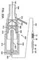
図21Aに示すように、弁12は、送達装置を体内へ挿入する前にバルーン上に装着されるのではなく、初めに、縮んだ状態で、ノーズピース508とテーパーウェッジ502との間のノーズカテーテルシャフト506上に装着される。弁は、当該弁をバルーン28上に載置することが望ましい場合にいつでも弁がシャフトに沿って移動できるように、ノーズカテーテルシャフト上に縮んだ状態にされる。ノーズピース508は、当該ノーズピースの近位端に、第1の孔部分512と第2の拡大された孔部分514とを備える段付き孔を有するように形成されてもよい。段付き孔は、第1および第2の孔部分の間に延び、第2の部分514内へ弁が挿入された際に弁12の遠位端と係合するように適合される、環状段部516を有するように形成されてもよい。ノーズピース508は、蛇行性の血管系を通る非侵襲的トラッキングを提供するために、ノーズピース508の遠位端へ向かう方向に先細になる外面を有してもよい。カバー510は、任意であってよく、弁が送達のためにノーズカテーテルシャフト上に位置付けられている場合、バルーン28、ウェッジ502、および弁12の少なくとも近位端部分上に延びてそれらを覆うように適合される。図示された実施形態において、カバー510の遠位端は、送達中に弁を完全に包囲するために、ノーズピース508の近位端に隣接するように位置付けられてもよい。代替的な実施形態において、カバー510は、送達中、弁またはバルーンの外面が覆われる部分が少なくなるように、さらに短い長さであってもよい。 As shown in FIG. 21A, the
ノーズピース508は、バルーンカテーテルに対して近位に(矢印518によって示す方向に)移動する際、ウェッジ502を越えバルーン28上へ弁12を押圧する。弁がウェッジ上を通過する際、弁がわずかに拡張し、バルーン上への当該弁の位置決めが容易になる。バルーンカテーテルシャフト26は、オペレータが弁をバルーン上の適切な場所に並置させるのを補助するために、放射線不透過性マーカー520(図21A)を有してもよい。ノーズピースは、比較的軟らかく可撓性の材料から形成された外層522と、比較的硬い材料から形成された内層524とを有してもよい。図示された実施形態内の内層524は、段部516と、第1の孔部分512の内面とを形成する。このようにして、ノーズピースは、ウェッジを越えてバルーン上へ弁12を押圧するのに十分な硬さを呈し、脈管への外傷を最小化するために軟らかい外面を提供する。例えば、外層522は55D Pebax(登録商標)から作製されてもよく、内層は55D Pebax(登録商標)よりも堅い72D Pebax(登録商標)から作製されてもよい。 As the
弁を装着する送達装置の区間は、一般に、体内へ挿入される装置の最大外径を画定する。弁12を、体内への挿入前にバルーン上ではなくノーズカテーテルシャフト上に装着することにより、弁12は、弁がバルーン上に装着される場合よりも小さい直径に縮まされ得る。したがって、送達装置の最大外径は、血管系内への、およびそれを通る挿入のために縮小され得る。上述のように、送達装置の最大直径を縮小することにより、大腿動脈に対する閉塞性が低くなり、それによって、当該手順中、患者の脚部は十分に灌流されたままの状態であることができる。いくつかの実施形態において、カバー510およびノーズピース508の(その近位端における)最大外径は約0.223インチであり、これは、体内へ挿入される送達装置の部分の最大直径である。ウェッジ502はその近位端において約0.120インチの直径を有してもよく、ガイドカテーテルシャフト22は約0.184インチの外径を有してもよい。 The section of the delivery device on which the valve is mounted generally defines the maximum outer diameter of the device that is inserted into the body. By mounting the
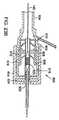
ここで、一実施形態による送達装置500の動作を説明すると、弁12は、最初、ノーズカテーテルシャフト上に装着され、ノーズピース508およびカバー510内へ挿入される。ガイドワイヤ140が体内に挿入された後、体から延びるワイヤの近位端はガイドワイヤ管腔の遠位端内へ挿入されることができ、送達装置500は脈管(例えば、大腿動脈)内へ挿入され、(図21Aに描写するように)体を通って前進することができる。あるいは、例えば、弁12を覆うためのカバー510が提供されない場合、まず導入用シースを脈管内へ挿入してもよい。導入用シースを挿入した後に、送達装置は、当該導入用シースを通って脈管内へ挿入され得る。 Turning now to the operation of the
送達装置の遠位端が、弁12をバルーン上へ摺動させるのに好都合な場所まで前進すると、ガイドカテーテルは、弁およびバルーンをカバー510から前進させるために、バルーンカテーテルに対して近位に退避させられる。例えば、人工弁を自然大動脈弁内に植え込む場合、弁およびバルーンは、上行大動脈内または左心室内へ前進させられることができ、続いて弁はバルーン上へ移動させられ得る。いずれの場合も、図21Bに示すように、ウェッジ502を越えてバルーン28上へ弁を前進させるために、ノーズカテーテルを近位に退避させることができる。マーカー520(図21A)を使用して、弁をバルーンの中心に据えることができる。弁をバルーン上に装着した後、図21Cに示すように、バルーンの膨張を妨害しないよう、ノーズカテーテルを遠位に前進させることができる。続いて、弁は、植え込み部位(例えば、自然大動脈弁内)に位置付けられ、バルーンを膨張させることによって設置されることができる。 As the distal end of the delivery device is advanced to a convenient location for sliding the
図22Aおよび22Bは、送達装置10(図1〜8)の修正形態を示す。図22Aおよび22Bの実施形態において、カバー23は略管状形状を有するが、ガイドカテーテルシャフト22の遠位端部分に巻き上げた状態で設けられている。弁12がバルーン28上に装着された後、患者の血管系内へそれを通って挿入するために、カバーは弁12上で展開され得る。図22Aおよび22Bに示す送達装置の動作は、その他の点では、図8A〜8Cを参照して上記で説明した送達装置10の動作と同一である。 22A and 22B show a modified form of delivery device 10 (FIGS. 1-8). In the embodiment of FIGS. 22A and 22B, the
図23Aおよび23Bは、送達装置の脈管内への挿入を容易にするために使用され得る、600で示す改良された導入用シースの一実施形態を示す。導入用シース600は、本願に記載の送達装置の実施形態等、人工弁を植え込むために使用される送達装置と共に使用するのに特に適している。導入用シース600は、種々の種類の腔内デバイス(例えば、ステント、ステントグラフト等)を載置するためのその他の種類の送達装置を、多種の血管および非血管性体腔(例えば、静脈、動脈、食道、胆道系の腺管、腸、尿道、卵管、その他の内分泌腺または外分泌腺管等)内へ導入するためにも使用され得る。図23Aに示す例は、人工弁12を植え込むために使用される送達装置の遠位端部分を示す。送達装置は、バルーンカテーテルとガイドカテーテルとを備える。バルーンカテーテルは、シャフト26と、当該シャフトの遠位端部分に装着されたバルーン28とを備える。ガイドカテーテルは、バルーンカテーテルシャフト26上に延びるシャフト22を備える。バルーンカテーテルおよびガイドカテーテルの残余部分は、図1〜8に示す実施形態にしたがって構築され得る。 FIGS. 23A and 23B show one embodiment of an improved introducer sheath at 600 that can be used to facilitate insertion of a delivery device into a vessel. The
従来の導入用シースは、バルーンカテーテル上に装着された弁に閉塞していない経路を提供するために、一般に、シースハウジング内のシールを通って挿入される管状ローダーを必要とする。ローダーは導入用シースの近位端から延び、それによってその作業長さを増大させ、体内に挿入され得る送達装置の利用可能な作業長さを減少させる。導入用シース600は、シースの作業長さを減少させ、それによって体内に挿入され得る送達装置の利用可能な作業長さを増大させるために、シースハウジング内に格納された一体型ローダーチューブを含む。 Conventional introducer sheaths generally require a tubular loader that is inserted through a seal in the sheath housing to provide an unobstructed path to a valve mounted on a balloon catheter. The loader extends from the proximal end of the introducer sheath, thereby increasing its working length and reducing the available working length of the delivery device that can be inserted into the body. Introducing
例えば、図示されたシース600は、シールハウジング602および当該ハウジングから遠位に延びる管状スリーブ604を含む。シールハウジング602は、図示された実施形態において示すように、クロススリット弁606、ディスク弁608、および止血弁610等の1つ以上のシール弁を格納する。これらの弁は、望ましくは、ポリイソプレン等の弾性生体適合材料から加工されるが、同様の生体適合材料を使用してもよい。弁606、608、610については、参照することにより本願に組み込まれる米国特許第6,379,372号においてさらに図示および記載されている。ディスク弁608とクロススリット弁606との間にスペーサ612を介在させてもよい。 For example, the illustrated
シールハウジングの近位端に連結されるのは、シールハウジングの長さに沿って縦方向に移動するように適合された末端部614である。図示された実施形態において、末端部は、シールハウジング602の外面上に形成された雄ネジ618と係合する雌ネジ616を有するように形成された、管状体を有する。したがって、末端部614の回転により、それをシールハウジングに対して内向きおよび外向きに移動させる。末端部614は、中央開口部620と、末端部の近位端部分に固定して取り付けられ、そこから遠位に延びる細長いローダーチューブ622とを有する。開口部620およびローダーチューブ622は、送達装置に装着された弁12(またはその他の人工器官)の通過を可能にするように寸法決定される。末端部614は、開口部620と並置された中央開口部を有する、シール624も格納する。シール624は、送達装置が導入用シース600内へ挿入されるとき、その外面とシール係合する。 Coupled to the proximal end of the seal housing is a
上述したように、末端部614は、シールハウジング602に対して内向きおよび外向きに調整され得る。末端部614を、図23Aに示す延びた位置から図23Bに示す退避位置まで調整することにより、ローダーチューブ622はシール606、608、610を通って移動し、弁12が導入用シースを通過するための閉塞していない経路を提供する。ローダーチューブは、末端部の背後に延びないため、ローダーチューブは、従来の導入用シースのようには血管系内へ挿入され得る送達装置の利用可能な作業長さを減少させない。 As described above, the
使用中、図23Aに示す延びた位置の導入用シース600は、先に挿入されたガイドワイヤ140上に載置され、スリーブ604が脈管内へ所望の距離だけ延びるまでその上を前進させられ得る。続いて、送達装置は、ガイドカテーテルシャフト22の周囲に液密シールを形成するシール624を有するローダーチューブ622内に弁12を位置付けるために、開口部620を通って挿入され得る。その後、弁606、608、610を通ってローダーチューブ622を摺動させる(図23B)ために末端部614を回転させ、それにより、スリーブ604の管腔および当該スリーブが挿入される脈管と連通させて送達装置を載置する。有利なことに、このアプローチは装填プロセスを簡略化し、弁をシース内へ装填するために必要なステップおよび部品の数を減少させる。 In use, the
導入用シース600の代替的な実施形態において、シールハウジング602は、末端部614上で雄ネジと係合する雌ネジを有してもよい。末端部は、前述のように、ローダーチューブ622の位置を調整するために回転され得る。また、シールハウジングおよび末端部上のネジのピッチを変動させて、シール弁を通ってローダーを延ばすために必要な回転運動の量を変動させることができる。別の実施形態において、末端部614は、当該末端部を回転させることなく押圧および牽引することにより、シールハウジングの長さに沿って摺動的に位置付け可能であってもよい。 In an alternative embodiment of
図24Aおよび24Bは、送達装置10(図1)において使用され得る、700で示すノーズカテーテルの別の実施形態を示す。ノーズカテーテル700は、ノーズピース702とノーズカテーテルシャフト704とを含む。ノーズピース702は、ノーズカテーテルシャフト704に接続された遠位端706と、バルーンカテーテルシャフト26の遠位端に接続された近位端とを有する。ノーズピース702は、ノーズピース702がバルーン28に対して付勢された際に弁12およびバルーン28またはその一部を覆う反転形状をとることができる、ナイロンまたはPET等の薄い可撓性材料から形成された、バルーンまたは同様の構造体を備える。例えば、ノーズピース702は、バルーン28と同様の構造を有してもよい。 FIGS. 24A and 24B show another embodiment of a nose catheter shown at 700 that may be used in the delivery device 10 (FIG. 1). The
ノーズカテーテルシャフト704はバルーンカテーテルシャフト26に対して摺動可能であるが、ノーズピース702の近位端は当該バルーンカテーテルシャフトに接続されている。したがって、ノーズカテーテルシャフト704がバルーンカテーテルシャフト26に対して近位に(矢印710の方向に)第1の延びた位置(図24B)から第2の退避位置(図24A)の方へ移動すると、ノーズピース702はバルーンカテーテルシャフト26の遠位端に対して付勢され、それにより、ノーズピース702は、バルーン28および弁12の外面の一部を覆う反転姿勢をとる。同様に、図24Bに示す延びた位置からノーズカテーテルシャフトに対して遠位にバルーンカテーテルシャフトを移動させることは、バルーンおよび弁上でノーズピースに反転姿勢をとらせるためにも効果的であることがわかる。 The
使用中、ノーズピース702は、患者の血管系を通る弁の送達中に円滑なトラッキング外形を提供するために、最初、図24Aに示す反転姿勢に載置される。植え込み部位またはその付近において、ノーズカテーテルシャフト704は、その後の弁の設置のために弁12およびバルーン28のカバーを取り外すために、バルーンカテーテルシャフト20に対して遠位に(矢印712の方向に)移動される。必須ではないが、望ましくは、図24Aに示す反転姿勢をさらに容易にとることができるように、ノーズピース702は部分的に膨張させられ得る。この関連で、ノーズカテーテルシャフト704の管腔は、バルーンカテーテルシャフトを使用して流体をバルーン28へ送達する手法と同様に、ノーズピース702を部分的に膨張させるための流体源と流体接続され得る。 In use, the
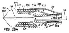
図25は、送達装置10の修正形態の遠位端部分を示す。本実施形態における送達装置は、バルーンカテーテルシャフト26および内部シャフト34の遠位端部分に装着された、段付きバルーン800を含む。図25Bに示すように、図示されたバルーン800は、第1の細身部分802、第1の円錐部分804、主円筒部分806、第2の円錐部分808、第2の円筒部分810、第3の円錐部分812、および第2の細身部分814を含む。弁12(図25A)は、主円筒部分806上に縮んだ状態で装着されてもよい。段付きバルーン800については、同時係属の米国出願第11/252,657号(‘657出願)(米国特許出願公開第2007/0088431号公報として公開)においてさらに詳細に記載されており、当該出願は参照することにより本願に組み込まれる。 FIG. 25 shows a distal end portion of a modified form of
図25Aに示すように、送達装置は、弁12の近位端に隣接する拡がった端部分816を有するガイドカテーテルシャフト22を備える、ガイドカテーテルを含む。ガイドカテーテルは、弁12上に延びてそれを覆う退避可能なカバー818をさらに含む。カバー818は、脈管の内部への設置用に弁のカバーを取り外すために、弁およびガイドカテーテルシャフト22の遠位端に対して縦方向に摺動するように動作可能である。バルーン800の部分802、804は、カバー818の遠位端から延び、バルーンカテーテルの遠位端とカバー818との間に遷移部材を提供するために部分的に膨張させられることができ、それにより、ノーズピース32(図1)と同様に、患者の血管系を通るトラッキングを容易にする。カバー818から延びるバルーンの端部は、‘657出願においてさらに記載されているように、弁を所望の植え込み部位に設置する前に、自然心臓弁
の狭窄弁尖または患者の血管系のその他の部分を開大させるための拡張器としても使用され得る。As shown in FIG. 25A, the delivery device includes a guide catheter comprising a
図25Aにさらに示すように、図示された実施形態内のカバー818は、弁12上に延びる円筒状遠位端部分820と、円筒状遠位端部分820の近位端から近位に延びる複数の円周方向に離間したフィンガー822とを有する。各フィンガー822の近位端部分は、ガイドカテーテルシャフト22内の各管腔を通って延びる牽引ワイヤ826と接続される。図25Cに示すように、各牽引ワイヤ826は、各管腔828から遠位に、各フィンガー822の近位端部分824内の開口部830を通って延び、管腔828内へ戻る。ガイドカテーテルは、ワイヤが血管系の内壁と接触するのを防止するために、牽引ワイヤ826の、シャフト22から延びる部分上に延びる可撓性の外カバー838をさらに含んでもよい。カバー838は、適切な接着剤等を用いて、シャフト22の外面に固定して取り付けられてもよい。あるいは、カバー838は、シャフト22に対して縦方向に摺動するように適合されてもよい。 As further shown in FIG. 25A, the
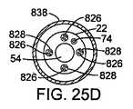
図示された例におけるカバー818は、それぞれが各管腔828を通って延びる牽引ワイヤ826に接続された4本のフィンガー822を有する。図25Dに示すように、管腔828は、シャフト22の中心管腔54の周囲で均等に離間していてもよい。シャフト22は、上述のように、ガイドカテーテルの曲率を調整する牽引ワイヤ74を受けるための別の管腔も含み得る。牽引ワイヤ826は、ガイドカテーテルシャフト22の長さだけ延び、牽引ワイヤ826、したがってカバー818の手動調整を可能にするために、シャフトの近位端において調整機構と動作可能に接続される。 The
図25Eは、ガイドカテーテルシャフトの近位端に接続されたハンドル部分832の概略図である。ハンドル部分832は、牽引ワイヤ826に接続されたさらなる調整機構834を含み得ることを除き、ハンドル部分20(上記で説明し、図3A〜3Bに示したもの)と同様の構成を有し得る。調整機構834は、牽引ワイヤ826を移動させるために、オペレータによって前後に(双頭矢印836の方向に)移動され得る。牽引ワイヤ826は、望ましくは、座屈させることなく、カバー818に遠位方向の押圧力を印加するのに十分な硬さを呈する。牽引ワイヤは、例えば、0.006インチ×0.012インチのニチノールリボンワイヤであってもよい。このようにして、カバー818は弁に対して近位方向に退避させられることができ、弁を回収してカバー818内へ戻すため等、必要に応じて、調整機構834の操作によって遠位方向に移動されることができる。牽引ワイヤの遠位方向および近位方向への運動を生み出すために使用され得る調整機構についてのさらなる詳細は、‘657出願において詳細に記載されている。 FIG. 25E is a schematic view of the
弁を体内の植え込み部位まで前進させると、弁のカバーを取り外すための調整機構の操作によって、カバー818は退避させられる。カバー818が(シャフト22および外カバー838に対して)退避するとき、シャフト端部分816の遠位端は、バルーン800上の弁の位置の不用意な運動を防止するために、弁と密接する。その後、バルーンカテーテルをガイドカテーテルに対して遠位に前進させて、弁12を設置するためのバルーンの完全な膨張を可能にするために十分な距離だけ、カバー838およびシャフト端部分816からバルーンカテーテル800を前進させることができる。弁12は、バルーンによって設置されるバルーンにより拡張可能な弁であってもよいし、あるいは、弁12は、カバー818から前進した際に半径方向に拡張する自己拡張式弁であってもよい。後者の場合において、バルーン800を使用して、自然弁のオリフィスとの密封係合を確実にするために弁をさらに拡張させることができる。 When the valve is advanced to the implantation site in the body, the
代替的な実施形態において、シャフト遠位端部分816は、‘657出願において詳細に記載されているような、弁12への解放可能な付着を提供するように構成され得る。このようにして、弁を設置する際に、脈管内における弁の位置を調整するために、ガイドカテーテルを前後に移動させることができる。設置前(または、弁の部分的設置、または拡張後)に、オペレータがガイドカテーテルを押圧、牽引、または捻じることによって、弁位置決めの制御が実現され得る。オペレータが弁の位置に満足すると、弁を完全に設置することができ、弁は、ガイドカテーテルシャフトの遠位端から切り離される。 In an alternative embodiment, the shaft
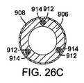
図25A〜25Eは、血管への送達装置の導入を容易にするために使用され得る、900で示される導入用シースの別の実施形態を示す。導入用シース900は、送達装置の最大部分(弁またはその他の人工デバイスが装着される部分)の挿入を容易にするために、第1の直径(図25A)から第2のさらに大きい直径(図25B)まで半径方向に拡張され得る、拡張可能な細長いスリーブ902を有する。シース900は、スリーブ902の近位端に接続されたハンドル部分904をさらに含む。スリーブ902は、内層906と外層908とを含む。内層906は、PEEK(ポリエーテルエーテルケトン)、ナイロン、またはポリプロピレン等の適切な材料から作製された編組ポリマー層であってもよい。外層908は、ウレタンまたは別の適切な材料から形成され得る。外層908の外面に、親水性皮膜を施してもよい。ハンドル部分904は、先に説明したように、シースを通って挿入された送達装置の外面とシール係合するように構成される1つ以上のシール弁を格納することができる。 25A-25E illustrate another embodiment of an introducer sheath, indicated at 900, that can be used to facilitate the introduction of a delivery device into a blood vessel. The
図25Cに示すように、スリーブ902は、送達装置の通過を可能にするようにサイズ決定された主管腔910と、主管腔910の周囲で離間した副管腔を画定する1つ以上の内部導管912とを有するように形成されてもよい。各副管腔を通って延びているのは、各牽引ワイヤ914である。各牽引ワイヤ914の近位端は、ハンドル部分904上の調整機構916と接続される。各牽引ワイヤ914の遠位端は、スリーブ902の遠位端部分に固定して取り付けられている。例えば、図25Dに示すように、各牽引ワイヤ914は、各管腔の遠位端から外向きに延び、てもよく、スリーブの遠位端に隣接する内層906に溶接されてもよい。 As shown in FIG. 25C, the
調整機構916は、スリーブ902の直径の、第1の直径(図25A)と第2のさらに大きい直径(図25B)との間での手動調整を可能にするように構成される。図示された実施形態において、例えば、調整機構は、ハンドル部分904に対して縦方向、つまり双頭矢印918で示す方向に移動することができる。調整機構を近位方向に(スリーブ902から離れて)移動させることは、牽引ワイヤ914を同じ方向に牽引し、それによってスリーブ902を半径方向に拡張し、その長さを短縮するために効果的である。調整機構914を遠位方向に(スリーブの方へ)移動させることにより、牽引ワイヤ914にかかっている張力を解放し、スリーブ902が半径方向に収縮し、自身の弾力性のもとで伸長することを可能にする。特定の実施形態において、スリーブ902は、その収縮状態で約18Fの外径を有し、約28Fの外径まで拡張することができる。
使用中、スリーブ902は先に説明したように血管内へ挿入され得る。送達装置(例えば、送達装置10)がスリーブ902を通って挿入されると、スリーブ902は半径方向に拡張され、人工弁(例えば、弁12)または送達装置に装着されたその他の人工デバイスがスリーブ902を容易に通過することを可能にすることができる。人工弁が血管内に挿入されると、血管の閉塞を最小化するために、スリーブ902の直径が低減され得る。 In use, the
代替的な実施形態において、図25Eに描写するように、内層906は、編組層ではなくレーザ切断チューブであってもよい。当該チューブは、チューブが半径方向に拡張および収縮することを可能にする、縦方向に延びる複数の切断部またはスリット920を有するように形成されてもよい。 In an alternative embodiment, as depicted in FIG. 25E, the
本願において開示する送達装置の種々の実施形態は、人工心臓弁以外の人工デバイスを体内に植え込むためにも使用され得る。例えば、送達装置は、種々の種類の腔内デバイス(例えば、ステント、ステントグラフト等)を、多種の血管内および非血管性体腔(例えば、静脈、動脈、食道、胆道系の腺管、腸、尿道、卵管、その他の内分泌腺または外分泌腺管等)内へ送達および設置するために使用され得る。1つの特定の実施形態において、送達装置は、バルーン拡張可能ステントを冠動脈(またはその他の血管)内に植え込み、血管腔の開通性を維持するために使用され得る。 Various embodiments of the delivery device disclosed herein can also be used to implant prosthetic devices other than prosthetic heart valves into the body. For example, the delivery device can be used to connect various types of intraluminal devices (eg, stents, stent grafts, etc.) to various intravascular and non-vascular body cavities (eg, veins, arteries, esophagus, gland ducts of the biliary system, intestines, urethra). , Fallopian tubes, other endocrine or exocrine glands, etc.). In one particular embodiment, the delivery device can be used to implant a balloon expandable stent within a coronary artery (or other blood vessel) and maintain patency of the vessel lumen.
開示されている発明の原理が適用され得る多くの考えられる実施形態を考慮すると、図示された実施形態は本発明の好適な例に過ぎず、本発明の範囲を限定するものとして解釈すべきではないことを認識すべきである。むしろ、本発明の範囲は、以下の特許請求の範囲によって定義される。したがって、出願人は、これらの請求項の範囲および精神に入るすべてを、本発明として請求するものである。 In view of the many possible embodiments to which the disclosed principles of the invention may be applied, the illustrated embodiments are merely preferred examples of the invention and should not be construed as limiting the scope of the invention. It should be recognized that there is no. Rather, the scope of the present invention is defined by the following claims. Accordingly, applicants claim as the invention all that comes within the scope and spirit of these claims.
Claims (22)
Translated fromJapanese細長いシャフトおよび該シャフトの遠位端部分に接続されたバルーンを備えるバルーンカテーテルであって、該バルーンは、該弁を縮んだ状態で担持するように適合され、該患者の体内の植え込み部位に該弁を設置するために膨張可能である、バルーンカテーテルと、
該バルーンカテーテルシャフト上を延びる細長いシャフトを備えるガイドカテーテルであって、該ガイドカテーテルのシャフトは操縦可能区間を備え、該ガイドカテーテルは、該操縦可能区間と動作可能に連結された調整機構をさらに備え、該調整機能は該操縦可能区間曲率を調整するように構成され、該バルーンカテーテルシャフトの部分は該操縦可能区間を通って延びる、ガイドカテーテルと、
ノーズカテーテルであって、該ノーズカテーテルは、該バルーンカテーテルシャフトを通って延びる細長いシャフトおよびノーズカテーテルシャフトの遠位端に接続されたノーズピースを備え、該ノーズピースは、該弁の送達中に、収縮状態の該バルーンの少なくとも遠位端部分を受けるように適合される内部孔を有する、ノーズカテーテルと
を備え、
該バルーンカテーテル、該ガイドカテーテル、および該ノーズカテーテルは、互いに対して縦方向に移動するように構成される、装置。A device for delivering a prosthetic valve through a patient's vasculature, comprising:
A balloon catheter comprising an elongate shaft and a balloon connected to a distal end portion of the shaft, the balloon being adapted to carry the valve in a collapsed state, at the implantation site in the patient's body A balloon catheter that is inflatable to install a valve;
A guide catheter comprising an elongate shaft extending over the balloon catheter shaft, wherein the guide catheter shaft further comprises a steerable section, the guide catheter further comprising an adjustment mechanism operably connected to the steerable section. The guide function configured to adjust the steerable section curvature, wherein a portion of the balloon catheter shaft extends through the steerable section;
A nose catheter comprising an elongated shaft extending through the balloon catheter shaft and a nosepiece connected to a distal end of the nose catheter shaft, the nosepiece during delivery of the valve; A nose catheter having an internal bore adapted to receive at least the distal end portion of the balloon in a deflated state,
The apparatus wherein the balloon catheter, the guide catheter, and the nose catheter are configured to move longitudinally relative to each other.
送達装置のバルーンカテーテルの膨張可能なバルーン上に該弁を載置するステップと、
該送達装置のノーズカテーテルのノーズピース内に該バルーンの少なくとも遠位端部分を挿入するステップと、
該バルーンカテーテルおよび該ノーズカテーテルを該体内に挿入し、該患者の血管系を通ってそれらを前進させるステップと、
該ノーズピースの内部にある該バルーンの部分のカバーを取り外すために、該バルーンカテーテルに対して遠位に該ノーズカテーテルを移動させるステップと、
該バルーンを膨張させることにより、該植え込み部位に該弁を設置するステップと
を含む、方法。A method of implanting a prosthetic valve at an implantation site in a patient's body,
Placing the valve on the inflatable balloon of the balloon catheter of the delivery device;
Inserting at least the distal end portion of the balloon into the nose piece of the nose catheter of the delivery device;
Inserting the balloon catheter and the nose catheter into the body and advancing them through the patient's vasculature;
Moving the nose catheter distally relative to the balloon catheter to remove a cover of the portion of the balloon that is internal to the nosepiece;
Placing the valve at the implantation site by inflating the balloon.
細長い送達装置の遠位端部分上に該弁を縮んだ状態で載置するステップと、
該患者の血管系を通って該送達装置を前進させるステップと、
該送達装置を前進させる行為の後に、該送達装置の該遠位端部分上の膨張可能なバルーンの上へ該縮んだ弁を移動させるステップと、
該バルーンを膨張させることにより、該植え込み部位に該弁を設置するステップと、
を含む、方法。A method of implanting a prosthetic valve at an implantation site in a patient's body,
Placing the valve in a compressed state on the distal end portion of the elongate delivery device;
Advancing the delivery device through the patient's vasculature;
After the act of advancing the delivery device, moving the collapsed valve onto an inflatable balloon on the distal end portion of the delivery device;
Placing the valve at the implantation site by inflating the balloon; and
Including a method.
該スリーブの該管腔と連通する内孔および該内孔に格納される1つ以上のシール弁を備えるシールハウジングと、
該スリーブの反対側で該シーリングハウジングに連結され、該内孔へ延びるローダーチューブを備える末端部であって、該1つ以上のシール弁から離間した第1の位置から該シール弁を通って該ローダーチューブが延びる第2の位置まで該ローダーチューブを移動させるために、該シールハウジングの長さに沿って移動可能な末端部と
を備える、導入用シース。An elongated tubular sleeve having a lumen and adapted to be inserted into a patient's vasculature;
A seal housing comprising an inner bore communicating with the lumen of the sleeve and one or more seal valves stored in the bore;
A distal end with a loader tube connected to the sealing housing on the opposite side of the sleeve and extending to the bore, through the seal valve from a first position spaced from the one or more seal valves. An introducer sheath comprising: a distal end movable along the length of the seal housing to move the loader tube to a second position where the loader tube extends.
Applications Claiming Priority (2)
| Application Number | Priority Date | Filing Date | Title |
|---|---|---|---|
| US84347006P | 2006-09-08 | 2006-09-08 | |
| PCT/US2007/078053WO2008031103A2 (en) | 2006-09-08 | 2007-09-10 | Integrated heart valve delivery system |
Publications (2)
| Publication Number | Publication Date |
|---|---|
| JP2009530070Atrue JP2009530070A (en) | 2009-08-27 |
| JP4682259B2 JP4682259B2 (en) | 2011-05-11 |
Family
ID=38962724
Family Applications (1)
| Application Number | Title | Priority Date | Filing Date |
|---|---|---|---|
| JP2009501764AActiveJP4682259B2 (en) | 2006-09-08 | 2007-09-10 | Integrated heart valve delivery system |
Country Status (10)
| Country | Link |
|---|---|
| US (14) | US8568472B2 (en) |
| EP (3) | EP2397108B1 (en) |
| JP (1) | JP4682259B2 (en) |
| CN (2) | CN101553190B (en) |
| AT (2) | ATE470410T1 (en) |
| AU (1) | AU2007294534B2 (en) |
| CA (5) | CA2878598C (en) |
| DE (1) | DE602007007050D1 (en) |
| ES (2) | ES2429220T3 (en) |
| WO (1) | WO2008031103A2 (en) |
Cited By (11)
| Publication number | Priority date | Publication date | Assignee | Title |
|---|---|---|---|---|
| JP2013538607A (en)* | 2010-08-17 | 2013-10-17 | ゴア エンタープライズ ホールディングス,インコーポレイティド | Forced deployment sequence handle assembly with independently operated mechanism |
| JP2013542771A (en)* | 2010-10-04 | 2013-11-28 | ザ・ジョンズ・ホプキンス・ユニバーシティー | Method and device for closure of intraluminal perforations |
| JP2015515024A (en)* | 2012-04-16 | 2015-05-21 | ダウ コーニング コーポレーションDow Corning Corporation | Sealed system for use with variable focus lenses |
| JP2016165493A (en)* | 2010-09-24 | 2016-09-15 | シメティス・ソシエテ・アノニムSymetis Sa | Stent valve, delivery device, and delivery method |
| JP2017518150A (en)* | 2014-04-28 | 2017-07-06 | エドワーズ ライフサイエンシーズ コーポレイションEdwards Lifesciences Corporation | Intravascular introducer device |
| JP2019504722A (en)* | 2015-12-23 | 2019-02-21 | マイクロポート エンドヴァスキュラー (シャンハイ) カンパニー リミテッド | Stent delivery system, assembly thereof, and method of use thereof |
| JP2019524197A (en)* | 2016-06-30 | 2019-09-05 | テンダイン ホールディングス,インコーポレイテッド | Prosthetic heart valve and apparatus and method for delivering the valve |
| JP2019531156A (en)* | 2016-10-20 | 2019-10-31 | シャンハイ マイクロポート カーディオフロー メドテック シーオー., エルティーディー.Shanghai Microport Cardioflow Medtech Co., Ltd. | Implant delivery device |
| JP2020526325A (en)* | 2017-07-13 | 2020-08-31 | バイオセンス・ウエブスター・(イスラエル)・リミテッドBiosense Webster (Israel), Ltd. | Adjustable instrument to extend the anatomical passage |
| JP2023529424A (en)* | 2020-06-08 | 2023-07-10 | エドワーズ ライフサイエンシーズ コーポレイション | Capsules for delivery devices for prosthetic medical devices |
| JP7725374B2 (en) | 2020-04-13 | 2025-08-19 | エドワーズ ライフサイエンシーズ コーポレイション | Intravascular delivery device having a variable length balloon |
Families Citing this family (579)
| Publication number | Priority date | Publication date | Assignee | Title |
|---|---|---|---|---|
| EP0850607A1 (en) | 1996-12-31 | 1998-07-01 | Cordis Corporation | Valve prosthesis for implantation in body channels |
| US6254564B1 (en) | 1998-09-10 | 2001-07-03 | Percardia, Inc. | Left ventricular conduit with blood vessel graft |
| US7018406B2 (en) | 1999-11-17 | 2006-03-28 | Corevalve Sa | Prosthetic valve for transluminal delivery |
| US8579966B2 (en) | 1999-11-17 | 2013-11-12 | Medtronic Corevalve Llc | Prosthetic valve for transluminal delivery |
| US8016877B2 (en) | 1999-11-17 | 2011-09-13 | Medtronic Corevalve Llc | Prosthetic valve for transluminal delivery |
| DE10010074B4 (en) | 2000-02-28 | 2005-04-14 | Fraunhofer-Gesellschaft zur Förderung der angewandten Forschung e.V. | Device for fastening and anchoring heart valve prostheses |
| DE10010073B4 (en)* | 2000-02-28 | 2005-12-22 | Fraunhofer-Gesellschaft zur Förderung der angewandten Forschung e.V. | Anchoring for implantable heart valve prostheses |
| US6454799B1 (en) | 2000-04-06 | 2002-09-24 | Edwards Lifesciences Corporation | Minimally-invasive heart valves and methods of use |
| AU2001273088A1 (en) | 2000-06-30 | 2002-01-30 | Viacor Incorporated | Intravascular filter with debris entrapment mechanism |
| US7556646B2 (en) | 2001-09-13 | 2009-07-07 | Edwards Lifesciences Corporation | Methods and apparatuses for deploying minimally-invasive heart valves |
| US6733525B2 (en) | 2001-03-23 | 2004-05-11 | Edwards Lifesciences Corporation | Rolled minimally-invasive heart valves and methods of use |
| US6770080B2 (en) | 2001-04-26 | 2004-08-03 | Fenestra Medical, Inc. | Mechanically registered videoscopic myringotomy/tympanostomy tube placement system |
| US8771302B2 (en) | 2001-06-29 | 2014-07-08 | Medtronic, Inc. | Method and apparatus for resecting and replacing an aortic valve |
| US8623077B2 (en) | 2001-06-29 | 2014-01-07 | Medtronic, Inc. | Apparatus for replacing a cardiac valve |
| US7544206B2 (en) | 2001-06-29 | 2009-06-09 | Medtronic, Inc. | Method and apparatus for resecting and replacing an aortic valve |
| FR2826863B1 (en) | 2001-07-04 | 2003-09-26 | Jacques Seguin | ASSEMBLY FOR PLACING A PROSTHETIC VALVE IN A BODY CONDUIT |
| FR2828263B1 (en) | 2001-08-03 | 2007-05-11 | Philipp Bonhoeffer | DEVICE FOR IMPLANTATION OF AN IMPLANT AND METHOD FOR IMPLANTATION OF THE DEVICE |
| US7097659B2 (en) | 2001-09-07 | 2006-08-29 | Medtronic, Inc. | Fixation band for affixing a prosthetic heart valve to tissue |
| US6893460B2 (en) | 2001-10-11 | 2005-05-17 | Percutaneous Valve Technologies Inc. | Implantable prosthetic valve |
| US8172856B2 (en) | 2002-08-02 | 2012-05-08 | Cedars-Sinai Medical Center | Methods and apparatus for atrioventricular valve repair |
| US7608114B2 (en) | 2002-12-02 | 2009-10-27 | Gi Dynamics, Inc. | Bariatric sleeve |
| US7025791B2 (en)* | 2002-12-02 | 2006-04-11 | Gi Dynamics, Inc. | Bariatric sleeve |
| WO2004049982A2 (en) | 2002-12-02 | 2004-06-17 | Gi Dynamics, Inc. | Bariatric sleeve |
| US20080264102A1 (en) | 2004-02-23 | 2008-10-30 | Bolton Medical, Inc. | Sheath Capture Device for Stent Graft Delivery System and Method for Operating Same |
| US7763063B2 (en) | 2003-09-03 | 2010-07-27 | Bolton Medical, Inc. | Self-aligning stent graft delivery system, kit, and method |
| US9198786B2 (en) | 2003-09-03 | 2015-12-01 | Bolton Medical, Inc. | Lumen repair device with capture structure |
| US20070198078A1 (en) | 2003-09-03 | 2007-08-23 | Bolton Medical, Inc. | Delivery system and method for self-centering a Proximal end of a stent graft |
| US8292943B2 (en) | 2003-09-03 | 2012-10-23 | Bolton Medical, Inc. | Stent graft with longitudinal support member |
| US8500792B2 (en) | 2003-09-03 | 2013-08-06 | Bolton Medical, Inc. | Dual capture device for stent graft delivery system and method for capturing a stent graft |
| US11596537B2 (en) | 2003-09-03 | 2023-03-07 | Bolton Medical, Inc. | Delivery system and method for self-centering a proximal end of a stent graft |
| US11259945B2 (en) | 2003-09-03 | 2022-03-01 | Bolton Medical, Inc. | Dual capture device for stent graft delivery system and method for capturing a stent graft |
| US9579194B2 (en) | 2003-10-06 | 2017-02-28 | Medtronic ATS Medical, Inc. | Anchoring structure with concave landing zone |
| AU2004305450B2 (en) | 2003-12-09 | 2009-01-08 | Gi Dynamics, Inc. | Intestinal sleeve |
| BRPI0510107A (en) | 2004-04-23 | 2007-09-25 | 3F Therapeutics Inc | implantable protein valve |
| US7331010B2 (en)* | 2004-10-29 | 2008-02-12 | International Business Machines Corporation | System, method and storage medium for providing fault detection and correction in a memory subsystem |
| DE102005003632A1 (en) | 2005-01-20 | 2006-08-17 | Fraunhofer-Gesellschaft zur Förderung der angewandten Forschung e.V. | Catheter for the transvascular implantation of heart valve prostheses |
| EP1845861B1 (en) | 2005-01-21 | 2011-06-22 | Mayo Foundation for Medical Education and Research | Thorascopic heart valve repair apparatus |
| ITTO20050074A1 (en) | 2005-02-10 | 2006-08-11 | Sorin Biomedica Cardio Srl | CARDIAC VALVE PROSTHESIS |
| US8608797B2 (en) | 2005-03-17 | 2013-12-17 | Valtech Cardio Ltd. | Mitral valve treatment techniques |
| US8333777B2 (en) | 2005-04-22 | 2012-12-18 | Benvenue Medical, Inc. | Catheter-based tissue remodeling devices and methods |
| US7914569B2 (en) | 2005-05-13 | 2011-03-29 | Medtronics Corevalve Llc | Heart valve prosthesis and methods of manufacture and use |
| US7780723B2 (en) | 2005-06-13 | 2010-08-24 | Edwards Lifesciences Corporation | Heart valve delivery system |
| GB0512321D0 (en) | 2005-06-16 | 2005-07-27 | Angiomed Ag | Catheter device double swaging |
| GB0512319D0 (en) | 2005-06-16 | 2005-07-27 | Angiomed Ag | Catheter device variable pusher |
| GB0512320D0 (en) | 2005-06-16 | 2005-07-27 | Angiomed Ag | Catheter device FLEXX tube |
| US8951285B2 (en) | 2005-07-05 | 2015-02-10 | Mitralign, Inc. | Tissue anchor, anchoring system and methods of using the same |
| EP1907042B1 (en) | 2005-07-06 | 2009-03-11 | Vascular Pathways Inc. | Intravenous catheter insertion device and method of use |
| EP1945142B1 (en) | 2005-09-26 | 2013-12-25 | Medtronic, Inc. | Prosthetic cardiac and venous valves |
| DE102005051849B4 (en) | 2005-10-28 | 2010-01-21 | JenaValve Technology Inc., Wilmington | Device for implantation and attachment of heart valve prostheses |
| DE102005052628B4 (en)* | 2005-11-04 | 2014-06-05 | Jenavalve Technology Inc. | Self-expanding, flexible wire mesh with integrated valvular prosthesis for the transvascular heart valve replacement and a system with such a device and a delivery catheter |
| US20070213813A1 (en) | 2005-12-22 | 2007-09-13 | Symetis Sa | Stent-valves for valve replacement and associated methods and systems for surgery |
| US8075615B2 (en) | 2006-03-28 | 2011-12-13 | Medtronic, Inc. | Prosthetic cardiac valve formed from pericardium material and methods of making same |
| EP3360509B1 (en) | 2006-07-31 | 2022-06-22 | Syntheon TAVR, LLC | Sealable endovascular implants |
| US9585743B2 (en) | 2006-07-31 | 2017-03-07 | Edwards Lifesciences Cardiaq Llc | Surgical implant devices and methods for their manufacture and use |
| US9408607B2 (en) | 2009-07-02 | 2016-08-09 | Edwards Lifesciences Cardiaq Llc | Surgical implant devices and methods for their manufacture and use |
| EP2397108B1 (en) | 2006-09-08 | 2013-08-07 | Edwards Lifesciences Corporation | Apparatus for treating a defective heart valve |
| US8834564B2 (en) | 2006-09-19 | 2014-09-16 | Medtronic, Inc. | Sinus-engaging valve fixation member |
| US11304800B2 (en) | 2006-09-19 | 2022-04-19 | Medtronic Ventor Technologies Ltd. | Sinus-engaging valve fixation member |
| US8876894B2 (en) | 2006-09-19 | 2014-11-04 | Medtronic Ventor Technologies Ltd. | Leaflet-sensitive valve fixation member |
| US9883943B2 (en) | 2006-12-05 | 2018-02-06 | Valtech Cardio, Ltd. | Implantation of repair devices in the heart |
| US11259924B2 (en) | 2006-12-05 | 2022-03-01 | Valtech Cardio Ltd. | Implantation of repair devices in the heart |
| JP5593545B2 (en) | 2006-12-06 | 2014-09-24 | メドトロニック シーブイ ルクセンブルク エス.アー.エール.エル. | System and method for transapical delivery of a self-expanding valve secured to an annulus |
| US8070799B2 (en) | 2006-12-19 | 2011-12-06 | Sorin Biomedica Cardio S.R.L. | Instrument and method for in situ deployment of cardiac valve prostheses |
| US20080147181A1 (en)* | 2006-12-19 | 2008-06-19 | Sorin Biomedica Cardio S.R.L. | Device for in situ axial and radial positioning of cardiac valve prostheses |
| US8236045B2 (en) | 2006-12-22 | 2012-08-07 | Edwards Lifesciences Corporation | Implantable prosthetic valve assembly and method of making the same |
| US8460369B2 (en)* | 2007-01-18 | 2013-06-11 | Valvexchange Inc. | Tools for removal and installation of exchangeable cardiovascular valves |
| EP2129332B1 (en) | 2007-02-16 | 2019-01-23 | Medtronic, Inc. | Replacement prosthetic heart valves |
| US11660190B2 (en) | 2007-03-13 | 2023-05-30 | Edwards Lifesciences Corporation | Tissue anchors, systems and methods, and devices |
| US9138315B2 (en) | 2007-04-13 | 2015-09-22 | Jenavalve Technology Gmbh | Medical device for treating a heart valve insufficiency or stenosis |
| US7896915B2 (en) | 2007-04-13 | 2011-03-01 | Jenavalve Technology, Inc. | Medical device for treating a heart valve insufficiency |
| US8249700B2 (en) | 2007-04-19 | 2012-08-21 | Acclarent, Inc. | System and method for the simultaneous bilateral integrated tympanic drug delivery and guided treatment of target tissues within the ears |
| FR2915087B1 (en) | 2007-04-20 | 2021-11-26 | Corevalve Inc | IMPLANT FOR TREATMENT OF A HEART VALVE, IN PARTICULAR OF A MITRAL VALVE, EQUIPMENT INCLUDING THIS IMPLANT AND MATERIAL FOR PLACING THIS IMPLANT. |
| EP2150304B1 (en) | 2007-05-07 | 2010-12-01 | Vascular Pathways Inc. | Intravenous catheter insertion and blood sample devices and method of use |
| EP2659861B1 (en)* | 2007-05-15 | 2019-03-13 | JenaValve Technology, Inc. | Handle for manipulating a catheter tip, catheter system and medical insertion system for inserting a self-expandable heart valve stent |
| US9566178B2 (en) | 2010-06-24 | 2017-02-14 | Edwards Lifesciences Cardiaq Llc | Actively controllable stent, stent graft, heart valve and method of controlling same |
| US9814611B2 (en) | 2007-07-31 | 2017-11-14 | Edwards Lifesciences Cardiaq Llc | Actively controllable stent, stent graft, heart valve and method of controlling same |
| CA2696055C (en)* | 2007-08-21 | 2013-12-10 | Valvexchange Inc. | Method and apparatus for prosthetic valve removal |
| US8808367B2 (en)* | 2007-09-07 | 2014-08-19 | Sorin Group Italia S.R.L. | Prosthetic valve delivery system including retrograde/antegrade approach |
| US8114154B2 (en) | 2007-09-07 | 2012-02-14 | Sorin Biomedica Cardio S.R.L. | Fluid-filled delivery system for in situ deployment of cardiac valve prostheses |
| DE102007043830A1 (en) | 2007-09-13 | 2009-04-02 | Lozonschi, Lucian, Madison | Heart valve stent |
| US9848981B2 (en) | 2007-10-12 | 2017-12-26 | Mayo Foundation For Medical Education And Research | Expandable valve prosthesis with sealing mechanism |
| CA2703129C (en) | 2007-10-18 | 2016-02-16 | Neochord Inc. | Minimially invasive repair of a valve leaflet in a beating heart |
| WO2009091509A1 (en) | 2008-01-16 | 2009-07-23 | St. Jude Medical, Inc. | Delivery and retrieval systems for collapsible/expandable prosthetic heart valves |
| CA2714062A1 (en) | 2008-01-24 | 2009-07-30 | Medtronic, Inc. | Stents for prosthetic heart valves |
| US9149358B2 (en) | 2008-01-24 | 2015-10-06 | Medtronic, Inc. | Delivery systems for prosthetic heart valves |
| US9393115B2 (en) | 2008-01-24 | 2016-07-19 | Medtronic, Inc. | Delivery systems and methods of implantation for prosthetic heart valves |
| US8157853B2 (en) | 2008-01-24 | 2012-04-17 | Medtronic, Inc. | Delivery systems and methods of implantation for prosthetic heart valves |
| US8628566B2 (en) | 2008-01-24 | 2014-01-14 | Medtronic, Inc. | Stents for prosthetic heart valves |
| US9044318B2 (en) | 2008-02-26 | 2015-06-02 | Jenavalve Technology Gmbh | Stent for the positioning and anchoring of a valvular prosthesis |
| US8465540B2 (en) | 2008-02-26 | 2013-06-18 | Jenavalve Technology, Inc. | Stent for the positioning and anchoring of a valvular prosthesis |
| US8398704B2 (en) | 2008-02-26 | 2013-03-19 | Jenavalve Technology, Inc. | Stent for the positioning and anchoring of a valvular prosthesis in an implantation site in the heart of a patient |
| US9168130B2 (en)* | 2008-02-26 | 2015-10-27 | Jenavalve Technology Gmbh | Stent for the positioning and anchoring of a valvular prosthesis in an implantation site in the heart of a patient |
| US8317858B2 (en) | 2008-02-26 | 2012-11-27 | Jenavalve Technology, Inc. | Stent for the positioning and anchoring of a valvular prosthesis in an implantation site in the heart of a patient |
| BR112012021347A2 (en) | 2008-02-26 | 2019-09-24 | Jenavalve Tecnology Inc | stent for positioning and anchoring a valve prosthesis at an implantation site in a patient's heart |
| WO2009108355A1 (en) | 2008-02-28 | 2009-09-03 | Medtronic, Inc. | Prosthetic heart valve systems |
| EP3912597A1 (en) | 2008-02-29 | 2021-11-24 | Edwards Lifesciences Corporation | Expandable member for deploying a prosthetic device |
| EP2247264A4 (en)* | 2008-02-29 | 2011-08-31 | Florida Int Univ Board Trustees | MULTI-SHEET ARTIFICIAL CARDIAC VALVE PROSTHESIS FOR CATHETER PLACEMENT, AND INTRAVASCULAR PLACEMENT SYSTEM FOR CARDIAC VALVE PROSTHESIS FOR CATHETER ARRANGEMENT |
| US8382829B1 (en) | 2008-03-10 | 2013-02-26 | Mitralign, Inc. | Method to reduce mitral regurgitation by cinching the commissure of the mitral valve |
| US8696689B2 (en) | 2008-03-18 | 2014-04-15 | Medtronic Ventor Technologies Ltd. | Medical suturing device and method for use thereof |
| US8430927B2 (en) | 2008-04-08 | 2013-04-30 | Medtronic, Inc. | Multiple orifice implantable heart valve and methods of implantation |
| US8696743B2 (en) | 2008-04-23 | 2014-04-15 | Medtronic, Inc. | Tissue attachment devices and methods for prosthetic heart valves |
| US8312825B2 (en) | 2008-04-23 | 2012-11-20 | Medtronic, Inc. | Methods and apparatuses for assembly of a pericardial prosthetic heart valve |
| US20090276040A1 (en) | 2008-05-01 | 2009-11-05 | Edwards Lifesciences Corporation | Device and method for replacing mitral valve |
| US9061119B2 (en) | 2008-05-09 | 2015-06-23 | Edwards Lifesciences Corporation | Low profile delivery system for transcatheter heart valve |
| EP2296744B1 (en) | 2008-06-16 | 2019-07-31 | Valtech Cardio, Ltd. | Annuloplasty devices |
| US8323335B2 (en) | 2008-06-20 | 2012-12-04 | Edwards Lifesciences Corporation | Retaining mechanisms for prosthetic valves and methods for using |
| CN102076281B (en)* | 2008-06-30 | 2014-11-05 | 波顿医疗公司 | Systems and methods for abdominal aortic aneurysm |
| US8652202B2 (en) | 2008-08-22 | 2014-02-18 | Edwards Lifesciences Corporation | Prosthetic heart valve and delivery apparatus |
| WO2010030859A1 (en)* | 2008-09-12 | 2010-03-18 | Valvexchange Inc. | Valve assembly with exchangeable valve member and a tool set for exchanging the valve member |
| WO2010031060A1 (en) | 2008-09-15 | 2010-03-18 | Medtronic Ventor Technologies Ltd. | Prosthetic heart valve having identifiers for aiding in radiographic positioning |
| US8137308B2 (en)* | 2008-09-16 | 2012-03-20 | Biosense Webster, Inc. | Catheter with adjustable deflection sensitivity |
| US8721714B2 (en)* | 2008-09-17 | 2014-05-13 | Medtronic Corevalve Llc | Delivery system for deployment of medical devices |
| CN102292053A (en) | 2008-09-29 | 2011-12-21 | 卡迪尔克阀门技术公司 | Heart valve |
| WO2010040009A1 (en) | 2008-10-01 | 2010-04-08 | Cardiaq Valve Technologies, Inc. | Delivery system for vascular implant |
| US8690936B2 (en) | 2008-10-10 | 2014-04-08 | Edwards Lifesciences Corporation | Expandable sheath for introducing an endovascular delivery device into a body |
| US8986361B2 (en) | 2008-10-17 | 2015-03-24 | Medtronic Corevalve, Inc. | Delivery system for deployment of medical devices |
| GB0822106D0 (en) | 2008-12-03 | 2009-01-07 | Angiomed Ag | Retractable catheter |
| US10517719B2 (en) | 2008-12-22 | 2019-12-31 | Valtech Cardio, Ltd. | Implantation of repair devices in the heart |
| US9011530B2 (en) | 2008-12-22 | 2015-04-21 | Valtech Cardio, Ltd. | Partially-adjustable annuloplasty structure |
| US8911494B2 (en) | 2009-05-04 | 2014-12-16 | Valtech Cardio, Ltd. | Deployment techniques for annuloplasty ring |
| WO2010073246A2 (en) | 2008-12-22 | 2010-07-01 | Valtech Cardio, Ltd. | Adjustable annuloplasty devices and adjustment mechanisms therefor |
| US8241351B2 (en) | 2008-12-22 | 2012-08-14 | Valtech Cardio, Ltd. | Adjustable partial annuloplasty ring and mechanism therefor |
| US8715342B2 (en) | 2009-05-07 | 2014-05-06 | Valtech Cardio, Ltd. | Annuloplasty ring with intra-ring anchoring |
| EP2682072A1 (en) | 2008-12-23 | 2014-01-08 | Sorin Group Italia S.r.l. | Expandable prosthetic valve having anchoring appendages |
| US10046141B2 (en)* | 2008-12-30 | 2018-08-14 | Biosense Webster, Inc. | Deflectable sheath introducer |
| US8353956B2 (en) | 2009-02-17 | 2013-01-15 | Valtech Cardio, Ltd. | Actively-engageable movement-restriction mechanism for use with an annuloplasty structure |
| EP3284447B1 (en) | 2009-03-13 | 2020-05-20 | Bolton Medical Inc. | System for deploying an endoluminal prosthesis at a surgical site |
| US8366767B2 (en) | 2009-03-30 | 2013-02-05 | Causper Medical Inc. | Methods and devices for transapical delivery of a sutureless valve prosthesis |
| CA2961053C (en) | 2009-04-15 | 2019-04-30 | Edwards Lifesciences Cardiaq Llc | Vascular implant and delivery system |
| NZ596179A (en) | 2009-04-29 | 2014-05-30 | Cleveland Clinic Foundation | Apparatus and method for replacing a diseased cardiac valve |
| US9968452B2 (en) | 2009-05-04 | 2018-05-15 | Valtech Cardio, Ltd. | Annuloplasty ring delivery cathethers |
| EP2250970B1 (en)* | 2009-05-13 | 2012-12-26 | Sorin Biomedica Cardio S.r.l. | Device for surgical interventions |
| US8403982B2 (en)* | 2009-05-13 | 2013-03-26 | Sorin Group Italia S.R.L. | Device for the in situ delivery of heart valves |
| US8353953B2 (en)* | 2009-05-13 | 2013-01-15 | Sorin Biomedica Cardio, S.R.L. | Device for the in situ delivery of heart valves |
| US20100292779A1 (en)* | 2009-05-15 | 2010-11-18 | Helmut Straubinger | Device for compressing a stent and a system as well as a method for loading a stent into a medical delivery system |
| US8920369B2 (en) | 2009-06-24 | 2014-12-30 | Shifamed Holdings, Llc | Steerable delivery sheaths |
| EP3862046A3 (en)* | 2009-07-14 | 2021-10-27 | Edwards Lifesciences Corporation | Transapical delivery system for heart valves |
| US8439970B2 (en)* | 2009-07-14 | 2013-05-14 | Edwards Lifesciences Corporation | Transapical delivery system for heart valves |
| US9770366B2 (en) | 2009-07-15 | 2017-09-26 | Tusker Medical, Inc. | Tympanic membrane pressure equalization tube delivery system |
| US9539146B2 (en) | 2009-07-15 | 2017-01-10 | Tusker Medical, Inc. | Trigger assembly for tympanostomy tube delivery device |
| EP2470119B1 (en) | 2009-08-27 | 2017-05-10 | Medtronic Inc. | Transcatheter valve delivery systems |
| JP5685256B2 (en)* | 2009-09-21 | 2015-03-18 | メドトロニック,インコーポレイテッド | Stented transcatheter prosthetic heart valve delivery system and method |
| US8652203B2 (en) | 2010-09-23 | 2014-02-18 | Cardiaq Valve Technologies, Inc. | Replacement heart valves, delivery devices and methods |
| US8808369B2 (en) | 2009-10-05 | 2014-08-19 | Mayo Foundation For Medical Education And Research | Minimally invasive aortic valve replacement |
| US9180007B2 (en) | 2009-10-29 | 2015-11-10 | Valtech Cardio, Ltd. | Apparatus and method for guide-wire based advancement of an adjustable implant |
| US10098737B2 (en) | 2009-10-29 | 2018-10-16 | Valtech Cardio, Ltd. | Tissue anchor for annuloplasty device |
| CN102665612B (en) | 2009-11-05 | 2015-04-08 | 宾夕法尼亚大学理事会 | Valve prosthesis |
| US8734467B2 (en) | 2009-12-02 | 2014-05-27 | Valtech Cardio, Ltd. | Delivery tool for implantation of spool assembly coupled to a helical anchor |
| US8449599B2 (en) | 2009-12-04 | 2013-05-28 | Edwards Lifesciences Corporation | Prosthetic valve for replacing mitral valve |
| US8870950B2 (en) | 2009-12-08 | 2014-10-28 | Mitral Tech Ltd. | Rotation-based anchoring of an implant |
| EP3300695B1 (en) | 2009-12-08 | 2023-05-24 | Avalon Medical Ltd. | Device and system for transcatheter mitral valve replacement |
| US9358109B2 (en)* | 2010-01-13 | 2016-06-07 | Vinay Badhwar | Transcorporeal delivery system and method |
| US9107749B2 (en)* | 2010-02-03 | 2015-08-18 | Edwards Lifesciences Corporation | Methods for treating a heart |
| US8518106B2 (en) | 2010-02-17 | 2013-08-27 | Medtronic, Inc. | Catheter assembly with valve crimping accessories |
| US8475523B2 (en)* | 2010-02-17 | 2013-07-02 | Medtronic, Inc. | Distal tip assembly for a heart valve delivery catheter |
| US8926693B2 (en)* | 2010-02-17 | 2015-01-06 | Medtronic, Inc. | Heart valve delivery catheter with safety button |
| JP5401613B2 (en)* | 2010-02-22 | 2014-01-29 | 上海交通大学医学院附属新華医院 | New slide fastener bioabsorbable stent transportation system |
| US9226826B2 (en) | 2010-02-24 | 2016-01-05 | Medtronic, Inc. | Transcatheter valve structure and methods for valve delivery |
| HUE059497T2 (en) | 2010-03-05 | 2022-11-28 | Edwards Lifesciences Corp | Support structures for heart valve prosthesis |
| US8652204B2 (en) | 2010-04-01 | 2014-02-18 | Medtronic, Inc. | Transcatheter valve with torsion spring fixation and related systems and methods |
| US8998980B2 (en) | 2010-04-09 | 2015-04-07 | Medtronic, Inc. | Transcatheter prosthetic heart valve delivery system with recapturing feature and method |
| US8926692B2 (en) | 2010-04-09 | 2015-01-06 | Medtronic, Inc. | Transcatheter prosthetic heart valve delivery device with partial deployment and release features and methods |
| US8512400B2 (en) | 2010-04-09 | 2013-08-20 | Medtronic, Inc. | Transcatheter heart valve delivery system with reduced area moment of inertia |
| US8512401B2 (en) | 2010-04-12 | 2013-08-20 | Medtronic, Inc. | Transcatheter prosthetic heart valve delivery system with funnel recapturing feature and method |
| US8579963B2 (en)* | 2010-04-13 | 2013-11-12 | Medtronic, Inc. | Transcatheter prosthetic heart valve delivery device with stability tube and method |
| US8740976B2 (en) | 2010-04-21 | 2014-06-03 | Medtronic, Inc. | Transcatheter prosthetic heart valve delivery system with flush report |
| US8876892B2 (en) | 2010-04-21 | 2014-11-04 | Medtronic, Inc. | Prosthetic heart valve delivery system with spacing |
| US8623075B2 (en) | 2010-04-21 | 2014-01-07 | Medtronic, Inc. | Transcatheter prosthetic heart valve delivery system and method with controlled expansion of prosthetic heart valve |
| US8568474B2 (en) | 2010-04-26 | 2013-10-29 | Medtronic, Inc. | Transcatheter prosthetic heart valve post-dilatation remodeling devices and methods |
| WO2011139746A1 (en) | 2010-04-27 | 2011-11-10 | Medtronic Inc. | Transcatheter prosthetic heart valve delivery device with passive trigger release |
| EP2563278B1 (en) | 2010-04-27 | 2018-07-11 | Medtronic, Inc. | Transcatheter prosthetic heart valve delivery device with biased release features |
| US8579964B2 (en) | 2010-05-05 | 2013-11-12 | Neovasc Inc. | Transcatheter mitral valve prosthesis |
| US9872971B2 (en) | 2010-05-14 | 2018-01-23 | C. R. Bard, Inc. | Guidewire extension system for a catheter placement device |
| US9950139B2 (en)* | 2010-05-14 | 2018-04-24 | C. R. Bard, Inc. | Catheter placement device including guidewire and catheter control elements |
| US11925779B2 (en) | 2010-05-14 | 2024-03-12 | C. R. Bard, Inc. | Catheter insertion device including top-mounted advancement components |
| US10384039B2 (en) | 2010-05-14 | 2019-08-20 | C. R. Bard, Inc. | Catheter insertion device including top-mounted advancement components |
| US8932258B2 (en) | 2010-05-14 | 2015-01-13 | C. R. Bard, Inc. | Catheter placement device and method |
| US11278406B2 (en) | 2010-05-20 | 2022-03-22 | Jenavalve Technology, Inc. | Catheter system for introducing an expandable heart valve stent into the body of a patient, insertion system with a catheter system and medical device for treatment of a heart valve defect |
| US10856978B2 (en) | 2010-05-20 | 2020-12-08 | Jenavalve Technology, Inc. | Catheter system |
| IT1400327B1 (en) | 2010-05-21 | 2013-05-24 | Sorin Biomedica Cardio Srl | SUPPORT DEVICE FOR VALVULAR PROSTHESIS AND CORRESPONDING CORRESPONDENT. |
| CN102258402B (en)* | 2010-05-25 | 2014-11-26 | 上海微创医疗器械(集团)有限公司 | Heart valve delivery system and delivery device |
| WO2011147849A1 (en) | 2010-05-25 | 2011-12-01 | Jenavalve Technology Inc. | Prosthetic heart valve and transcatheter delivered endoprosthesis comprising a prosthetic heart valve and a stent |
| US9387077B2 (en) | 2010-05-27 | 2016-07-12 | Medtronic Vascular Galway | Catheter assembly with prosthesis crimping and prosthesis retaining accessories |
| US9561102B2 (en) | 2010-06-02 | 2017-02-07 | Medtronic, Inc. | Transcatheter delivery system and method with controlled expansion and contraction of prosthetic heart valve |
| US8419783B2 (en)* | 2010-07-07 | 2013-04-16 | Cook Medical Technologies Llc | Graft deployment assist tool |
| AU2011275468B2 (en) | 2010-07-09 | 2014-02-06 | Highlife Sas | Transcatheter atrio-ventricular valve prosthesis |
| JP5906239B2 (en) | 2010-07-15 | 2016-04-20 | セント・ジュード・メディカル,インコーポレイテッド | Retainer for transcatheter heart valve delivery system |
| US9763657B2 (en) | 2010-07-21 | 2017-09-19 | Mitraltech Ltd. | Techniques for percutaneous mitral valve replacement and sealing |
| US11653910B2 (en) | 2010-07-21 | 2023-05-23 | Cardiovalve Ltd. | Helical anchor implantation |
| US9326853B2 (en) | 2010-07-23 | 2016-05-03 | Edwards Lifesciences Corporation | Retaining mechanisms for prosthetic valves |
| US10130470B2 (en) | 2010-08-17 | 2018-11-20 | St. Jude Medical, Llc | Sleeve for facilitating movement of a transfemoral catheter |
| US9248262B2 (en) | 2010-08-31 | 2016-02-02 | Vibha Agarwal | Vascular dilator for controlling blood flow in a blood vessel |
| US8641757B2 (en) | 2010-09-10 | 2014-02-04 | Edwards Lifesciences Corporation | Systems for rapidly deploying surgical heart valves |
| US9125741B2 (en) | 2010-09-10 | 2015-09-08 | Edwards Lifesciences Corporation | Systems and methods for ensuring safe and rapid deployment of prosthetic heart valves |
| EP2428189A1 (en)* | 2010-09-10 | 2012-03-14 | Symetis Sa | Catheter delivery system for stent valve |
| JP2013540481A (en) | 2010-09-17 | 2013-11-07 | セント・ジュード・メディカル,カーディオロジー・ディヴィジョン,インコーポレイテッド | Retainer for transcatheter heart valve delivery system |
| CN103118584B (en) | 2010-09-22 | 2016-06-22 | 阿克拉伦特公司 | Device for treating paranasal sinus conditions |
| JP5922129B2 (en)* | 2010-09-22 | 2016-05-24 | アクラレント インコーポレイテッド | Medical device for treatment of sinus opening |
| EP3673871B8 (en)* | 2010-09-24 | 2024-01-24 | Boston Scientific Medical Device Limited | A transcatheter aortic valve implantation system |
| DK4233795T3 (en)* | 2010-10-05 | 2024-08-26 | Edwards Lifesciences Corp | Prosthetic heart valve |
| ES2566166T3 (en)* | 2010-10-20 | 2016-04-11 | Stryker Corporation | Stent delivery catheter with rapid exchange capabilities |
| US9072872B2 (en) | 2010-10-29 | 2015-07-07 | Medtronic, Inc. | Telescoping catheter delivery system for left heart endocardial device placement |
| US8560086B2 (en) | 2010-12-02 | 2013-10-15 | St. Jude Medical, Atrial Fibrillation Division, Inc. | Catheter electrode assemblies and methods of construction therefor |
| EP2658480B1 (en) | 2010-12-29 | 2017-11-01 | Neochord Inc. | Exchangeable system for minimally invasive beating heart repair of heart valve leaflets |
| EP2658483B1 (en)* | 2010-12-30 | 2018-07-11 | Boston Scientific Scimed, Inc. | Loading basket for a stent delivery system |
| US8690833B2 (en) | 2011-01-31 | 2014-04-08 | Vascular Pathways, Inc. | Intravenous catheter and insertion device with reduced blood spatter |
| ES2641902T3 (en) | 2011-02-14 | 2017-11-14 | Sorin Group Italia S.R.L. | Sutureless anchoring device for cardiac valve prostheses |
| EP2486894B1 (en) | 2011-02-14 | 2021-06-09 | Sorin Group Italia S.r.l. | Sutureless anchoring device for cardiac valve prostheses |
| US9155619B2 (en) | 2011-02-25 | 2015-10-13 | Edwards Lifesciences Corporation | Prosthetic heart valve delivery apparatus |
| ES2835652T3 (en) | 2011-02-25 | 2021-06-22 | Bard Inc C R | Medical component insertion device including a retractable needle |
| US9554897B2 (en) | 2011-04-28 | 2017-01-31 | Neovasc Tiara Inc. | Methods and apparatus for engaging a valve prosthesis with tissue |
| US9308087B2 (en) | 2011-04-28 | 2016-04-12 | Neovasc Tiara Inc. | Sequentially deployed transcatheter mitral valve prosthesis |
| USD903101S1 (en) | 2011-05-13 | 2020-11-24 | C. R. Bard, Inc. | Catheter |
| US20120303048A1 (en) | 2011-05-24 | 2012-11-29 | Sorin Biomedica Cardio S.R.I. | Transapical valve replacement |
| US9289282B2 (en) | 2011-05-31 | 2016-03-22 | Edwards Lifesciences Corporation | System and method for treating valve insufficiency or vessel dilatation |
| CN103813757A (en) | 2011-06-01 | 2014-05-21 | 尼奥绰德有限公司 | Minimally Invasive Repair of heart valve leaflets |
| EP3345573B1 (en) | 2011-06-23 | 2020-01-29 | Valtech Cardio, Ltd. | Closure element for use with annuloplasty structure |
| US9918840B2 (en) | 2011-06-23 | 2018-03-20 | Valtech Cardio, Ltd. | Closed band for percutaneous annuloplasty |
| US10792152B2 (en) | 2011-06-23 | 2020-10-06 | Valtech Cardio, Ltd. | Closed band for percutaneous annuloplasty |
| US9119716B2 (en)* | 2011-07-27 | 2015-09-01 | Edwards Lifesciences Corporation | Delivery systems for prosthetic heart valve |
| EP2736450A1 (en) | 2011-07-28 | 2014-06-04 | St. Jude Medical, Inc. | Expandable radiopaque marker for transcatheter aortic valve implantation |
| EP4289398A3 (en) | 2011-08-11 | 2024-03-13 | Tendyne Holdings, Inc. | Improvements for prosthetic valves and related inventions |
| US9827093B2 (en) | 2011-10-21 | 2017-11-28 | Edwards Lifesciences Cardiaq Llc | Actively controllable stent, stent graft, heart valve and method of controlling same |
| US9510947B2 (en) | 2011-10-21 | 2016-12-06 | Jenavalve Technology, Inc. | Catheter system for introducing an expandable heart valve stent into the body of a patient |
| US8858623B2 (en) | 2011-11-04 | 2014-10-14 | Valtech Cardio, Ltd. | Implant having multiple rotational assemblies |
| EP3656434B1 (en)* | 2011-11-08 | 2021-10-20 | Valtech Cardio, Ltd. | Controlled steering functionality for implant-delivery tool |
| US11213318B2 (en) | 2011-11-10 | 2022-01-04 | Medtronic Vascular, Inc. | Expandable introducer sheath and method |
| AU2012335016B2 (en) | 2011-11-10 | 2017-07-20 | Medtronic, Inc. | System for deploying a device to a distal location across a diseased vessel |
| US9199061B2 (en)* | 2011-11-18 | 2015-12-01 | Biosense Webster (Israel) Ltd. | Medical device control handle |
| CN104114127B (en) | 2011-12-09 | 2017-09-05 | 爱德华兹生命科学公司 | Prosthetic heart valve with improved commissural support |
| EP2881083B1 (en) | 2011-12-12 | 2017-03-22 | David Alon | Heart valve repair device |
| US9827092B2 (en) | 2011-12-16 | 2017-11-28 | Tendyne Holdings, Inc. | Tethers for prosthetic mitral valve |
| EP2606920A1 (en) | 2011-12-22 | 2013-06-26 | ECP Entwicklungsgesellschaft mbH | Sluice device for inserting a catheter |
| EP2606919A1 (en) | 2011-12-22 | 2013-06-26 | ECP Entwicklungsgesellschaft mbH | Sluice device for inserting a catheter |
| US10028854B2 (en) | 2012-02-02 | 2018-07-24 | Covidien Lp | Stent retaining systems |
| WO2013130641A1 (en) | 2012-02-29 | 2013-09-06 | Valcare, Inc. | Percutaneous annuloplasty system with anterior-posterior adjustment |
| EP2846743B1 (en) | 2012-04-12 | 2016-12-14 | Bolton Medical Inc. | Vascular prosthetic delivery device |
| US8920485B2 (en)* | 2012-04-13 | 2014-12-30 | Medtronic Vascular, Inc. | Stent-graft delivery system having a rotatable single shaft tip capture mechanism |
| US9445897B2 (en) | 2012-05-01 | 2016-09-20 | Direct Flow Medical, Inc. | Prosthetic implant delivery device with introducer catheter |
| EP2849678B1 (en) | 2012-05-16 | 2022-08-10 | JenaValve Technology, Inc. | Catheter delivery system for introducing an expandable heart valve prosthesis and medical device for the treatment of a heart valve defect |
| US9345573B2 (en) | 2012-05-30 | 2016-05-24 | Neovasc Tiara Inc. | Methods and apparatus for loading a prosthesis onto a delivery system |
| US9480561B2 (en) | 2012-06-26 | 2016-11-01 | St. Jude Medical, Cardiology Division, Inc. | Apparatus and method for aortic protection and TAVI planar alignment |
| US9918837B2 (en) | 2012-06-29 | 2018-03-20 | St. Jude Medical, Cardiology Division, Inc. | System to assist in the release of a collapsible stent from a delivery device |
| US20140031923A1 (en)* | 2012-07-25 | 2014-01-30 | Medtronic Vascular Galway Limited | Trans-Aortic Surgical Syringe-Type Device for Deployment of a Prosthetic Valve |
| WO2014022124A1 (en) | 2012-07-28 | 2014-02-06 | Tendyne Holdings, Inc. | Improved multi-component designs for heart valve retrieval device, sealing structures and stent assembly |
| WO2014021905A1 (en) | 2012-07-30 | 2014-02-06 | Tendyne Holdings, Inc. | Improved delivery systems and methods for transcatheter prosthetic valves |
| US9717595B2 (en)* | 2012-09-05 | 2017-08-01 | Medtronic Vascular Galway | Trans-aortic delivery system with containment capsule centering device |
| US9510946B2 (en) | 2012-09-06 | 2016-12-06 | Edwards Lifesciences Corporation | Heart valve sealing devices |
| US9216018B2 (en) | 2012-09-29 | 2015-12-22 | Mitralign, Inc. | Plication lock delivery system and method of use thereof |
| EP2911593B1 (en) | 2012-10-23 | 2020-03-25 | Valtech Cardio, Ltd. | Percutaneous tissue anchor techniques |
| WO2014064694A2 (en) | 2012-10-23 | 2014-05-01 | Valtech Cardio, Ltd. | Controlled steering functionality for implant-delivery tool |
| US9907931B2 (en) | 2012-10-26 | 2018-03-06 | Medtronic, Inc. | Elastic introducer sheath |
| US9192751B2 (en) | 2012-10-26 | 2015-11-24 | Medtronic, Inc. | Elastic introducer sheath |
| EP4162902A1 (en) | 2012-11-21 | 2023-04-12 | Edwards Lifesciences Corporation | Retaining mechanisms for prosthetic heart valves |
| WO2014087402A1 (en) | 2012-12-06 | 2014-06-12 | Valtech Cardio, Ltd. | Techniques for guide-wire based advancement of a tool |
| EP2745869A1 (en) | 2012-12-21 | 2014-06-25 | ECP Entwicklungsgesellschaft mbH | Sluice assembly for the introduction of a cord-like body, in particular of a catheter, into a patient |
| US20140200639A1 (en) | 2013-01-16 | 2014-07-17 | Advanced Neuromodulation Systems, Inc. | Self-expanding neurostimulation leads having broad multi-electrode arrays |
| US20150351906A1 (en) | 2013-01-24 | 2015-12-10 | Mitraltech Ltd. | Ventricularly-anchored prosthetic valves |
| US9439763B2 (en) | 2013-02-04 | 2016-09-13 | Edwards Lifesciences Corporation | Prosthetic valve for replacing mitral valve |
| US9168129B2 (en) | 2013-02-12 | 2015-10-27 | Edwards Lifesciences Corporation | Artificial heart valve with scalloped frame design |
| EP2961351B1 (en) | 2013-02-26 | 2018-11-28 | Mitralign, Inc. | Devices for percutaneous tricuspid valve repair |
| WO2014138482A1 (en) | 2013-03-07 | 2014-09-12 | Cedars-Sinai Medical Center | Method and apparatus for percutaneous delivery and deployment of a cardiovascular prosthesis |
| US10080657B2 (en) | 2013-03-07 | 2018-09-25 | Cedars-Sinai Medical Center | Catheter based apical approach heart prostheses delivery system |
| US10583002B2 (en) | 2013-03-11 | 2020-03-10 | Neovasc Tiara Inc. | Prosthetic valve with anti-pivoting mechanism |
| US9333077B2 (en) | 2013-03-12 | 2016-05-10 | Medtronic Vascular Galway Limited | Devices and methods for preparing a transcatheter heart valve system |
| US9681891B2 (en) | 2013-03-14 | 2017-06-20 | Tusker Medical, Inc. | Tympanostomy tube delivery device with cutting dilator |
| US11406497B2 (en) | 2013-03-14 | 2022-08-09 | Jc Medical, Inc. | Heart valve prosthesis |
| US9320652B2 (en) | 2013-03-14 | 2016-04-26 | Tusker Medical, Inc. | Features to improve and sense tympanic membrane apposition by tympanostomy tube delivery instrument |
| US20140277427A1 (en) | 2013-03-14 | 2014-09-18 | Cardiaq Valve Technologies, Inc. | Prosthesis for atraumatically grasping intralumenal tissue and methods of delivery |
| US9681951B2 (en) | 2013-03-14 | 2017-06-20 | Edwards Lifesciences Cardiaq Llc | Prosthesis with outer skirt and anchors |
| US11259923B2 (en) | 2013-03-14 | 2022-03-01 | Jc Medical, Inc. | Methods and devices for delivery of a prosthetic valve |
| US10449333B2 (en)* | 2013-03-14 | 2019-10-22 | Valtech Cardio, Ltd. | Guidewire feeder |
| CA2905422A1 (en) | 2013-03-14 | 2014-10-02 | Cardiovantage Medical, Inc. | Embolic protection devices and methods of use |
| US9439751B2 (en) | 2013-03-15 | 2016-09-13 | Bolton Medical, Inc. | Hemostasis valve and delivery systems |
| CN105283214B (en) | 2013-03-15 | 2018-10-16 | 北京泰德制药股份有限公司 | Translate conduit, system and its application method |
| US10463489B2 (en) | 2013-04-02 | 2019-11-05 | Tendyne Holdings, Inc. | Prosthetic heart valve and systems and methods for delivering the same |
| US9486306B2 (en) | 2013-04-02 | 2016-11-08 | Tendyne Holdings, Inc. | Inflatable annular sealing device for prosthetic mitral valve |
| US11224510B2 (en) | 2013-04-02 | 2022-01-18 | Tendyne Holdings, Inc. | Prosthetic heart valve and systems and methods for delivering the same |
| US9572665B2 (en) | 2013-04-04 | 2017-02-21 | Neovasc Tiara Inc. | Methods and apparatus for delivering a prosthetic valve to a beating heart |
| US10478293B2 (en) | 2013-04-04 | 2019-11-19 | Tendyne Holdings, Inc. | Retrieval and repositioning system for prosthetic heart valve |
| WO2014179763A1 (en) | 2013-05-03 | 2014-11-06 | Medtronic Inc. | Valve delivery tool |
| CA2912204A1 (en) | 2013-05-17 | 2014-11-20 | Transaortic Medical, Inc. | Expandable introducer sheath |
| EP2999436B1 (en) | 2013-05-20 | 2018-08-29 | Edwards Lifesciences Corporation | Prosthetic heart valve delivery apparatus |
| CN104173121B (en) | 2013-05-27 | 2016-05-25 | 上海微创心通医疗科技有限公司 | For delivery of electric handle and the induction system of implant |
| US9610159B2 (en) | 2013-05-30 | 2017-04-04 | Tendyne Holdings, Inc. | Structural members for prosthetic mitral valves |
| US9788943B2 (en) | 2013-06-11 | 2017-10-17 | Medtronic, Inc. | Delivery system with inline sheath |
| CN105658178B (en) | 2013-06-25 | 2018-05-08 | 坦迪尼控股股份有限公司 | Thrombus management and structural compliance features for prosthetic heart valves |
| WO2015013238A2 (en) | 2013-07-22 | 2015-01-29 | Mayo Foundation For Medical Education And Research | Device and methods for self-centering a guide catheter |
| AU2014296087B2 (en) | 2013-08-01 | 2019-08-01 | Tendyne Holdings, Inc. | Epicardial anchor devices and methods |
| US9919137B2 (en) | 2013-08-28 | 2018-03-20 | Edwards Lifesciences Corporation | Integrated balloon catheter inflation system |
| CN105491978A (en) | 2013-08-30 | 2016-04-13 | 耶拿阀门科技股份有限公司 | Radially collapsible frame for a prosthetic valve and method for manufacturing such a frame |
| US10070857B2 (en) | 2013-08-31 | 2018-09-11 | Mitralign, Inc. | Devices and methods for locating and implanting tissue anchors at mitral valve commissure |
| CN103446655A (en)* | 2013-09-04 | 2013-12-18 | 杭州启明医疗器械有限公司 | Deflectable sheathing canal and delivery system with deflectable sheathing canal |
| US10195028B2 (en) | 2013-09-10 | 2019-02-05 | Edwards Lifesciences Corporation | Magnetic retaining mechanisms for prosthetic valves |
| CN103479453A (en)* | 2013-10-14 | 2014-01-01 | 黄景陶 | Implantation device for precisely locating human body endoluminal stent |
| WO2015058039A1 (en) | 2013-10-17 | 2015-04-23 | Robert Vidlund | Apparatus and methods for alignment and deployment of intracardiac devices |
| WO2015059699A2 (en) | 2013-10-23 | 2015-04-30 | Valtech Cardio, Ltd. | Anchor magazine |
| EP3398562B2 (en) | 2013-10-28 | 2025-10-08 | Boston Scientific Medical Device Limited | Stent-valve, delivery apparatus and method |
| EP3062744B1 (en) | 2013-10-28 | 2020-01-22 | Tendyne Holdings, Inc. | Prosthetic heart valve and systems for delivering the same |
| US9526611B2 (en) | 2013-10-29 | 2016-12-27 | Tendyne Holdings, Inc. | Apparatus and methods for delivery of transcatheter prosthetic valves |
| AU2013257415B1 (en)* | 2013-11-08 | 2014-06-26 | Cook Medical Technologies Llc | An endograft introducer and a capsule assembly for an endograft introducer |
| US9622863B2 (en) | 2013-11-22 | 2017-04-18 | Edwards Lifesciences Corporation | Aortic insufficiency repair device and method |
| US10098734B2 (en) | 2013-12-05 | 2018-10-16 | Edwards Lifesciences Corporation | Prosthetic heart valve and delivery apparatus |
| EP3082930B1 (en)* | 2013-12-20 | 2019-07-17 | Boston Scientific Scimed, Inc. | Integrated catheter system |
| US9610162B2 (en) | 2013-12-26 | 2017-04-04 | Valtech Cardio, Ltd. | Implantation of flexible implant |
| WO2015120122A2 (en) | 2014-02-05 | 2015-08-13 | Robert Vidlund | Apparatus and methods for transfemoral delivery of prosthetic mitral valve |
| AU2014200686B1 (en)* | 2014-02-05 | 2014-06-26 | Cook Medical Technologies Llc | An endograft introducer and a capsule assembly for an endograft introducer |
| US9986993B2 (en) | 2014-02-11 | 2018-06-05 | Tendyne Holdings, Inc. | Adjustable tether and epicardial pad system for prosthetic heart valve |
| CN108836414B (en) | 2014-02-14 | 2021-06-29 | 爱德华兹生命科学公司 | Percutaneous leaflet augmentation |
| JP6865037B2 (en) | 2014-03-10 | 2021-04-28 | テンダイン ホールディングス,インコーポレイテッド | Devices and methods for positioning the artificial mitral valve and monitoring the tether load of the artificial mitral valve |
| US10149758B2 (en) | 2014-04-01 | 2018-12-11 | Medtronic, Inc. | System and method of stepped deployment of prosthetic heart valve |
| US9381083B2 (en) | 2014-04-11 | 2016-07-05 | Medtronic Vascular Galway | Profile altering tip for a delivery system |
| US10413410B2 (en) | 2014-04-11 | 2019-09-17 | Medtronic Vascular, Inc. | Profile altering tip for a delivery system |
| US10076644B2 (en) | 2014-05-16 | 2018-09-18 | Terumo Kabushiki Kaisha | Method and apparatus for treating urethral stricture |
| US9883937B2 (en)* | 2014-05-16 | 2018-02-06 | Terumo Kabushiki Kaisha | Method and apparatus for treating urethral stricture |
| US9532870B2 (en) | 2014-06-06 | 2017-01-03 | Edwards Lifesciences Corporation | Prosthetic valve for replacing a mitral valve |
| US10195026B2 (en) | 2014-07-22 | 2019-02-05 | Edwards Lifesciences Corporation | Mitral valve anchoring |
| EP3174502B1 (en) | 2014-07-30 | 2022-04-06 | Cardiovalve Ltd | Apparatus for implantation of an articulatable prosthetic valve |
| US20160038341A1 (en) | 2014-08-08 | 2016-02-11 | Acclarent, Inc. | Tympanostomy tube delivery device with elastomeric brake |
| US10195086B2 (en) | 2014-08-11 | 2019-02-05 | Tusker Medical, Inc. | Tympanostomy tube delivery device with rotatable |
| US9833360B2 (en)* | 2014-08-12 | 2017-12-05 | Tusker Medical, Inc. | Tympanostomy tube delivery device with replaceable shaft portion |
| US9833359B2 (en) | 2014-08-12 | 2017-12-05 | Tusker Medical, Inc. | Tympanostomy tube delivery device with cutter force clutch |
| US10058424B2 (en) | 2014-08-21 | 2018-08-28 | Edwards Lifesciences Corporation | Dual-flange prosthetic valve frame |
| WO2016037127A1 (en) | 2014-09-05 | 2016-03-10 | C.R. Bard, Inc. | Catheter insertion device including retractable needle |
| WO2016040526A1 (en) | 2014-09-10 | 2016-03-17 | Cedars-Sinai Medical Center | Method and apparatus for percutaneous delivery and deployment of a cardiac valve prosthesis |
| US9700699B2 (en) | 2014-09-12 | 2017-07-11 | Freudenberg Medical, Llc | Modular handle assembly for a steerable catheter |
| KR20170066470A (en) | 2014-09-28 | 2017-06-14 | 카디오키네틱스 인크. | Apparatuses for treating cardiac dysfunction |
| US10390950B2 (en) | 2014-10-03 | 2019-08-27 | St. Jude Medical, Cardiology Division, Inc. | Flexible catheters and methods of forming same |
| EP3922213A1 (en) | 2014-10-14 | 2021-12-15 | Valtech Cardio, Ltd. | Leaflet-restraining techniques |
| US10758265B2 (en) | 2014-11-14 | 2020-09-01 | Cedars-Sinai Medical Center | Cardiovascular access and device delivery system |
| US20160144156A1 (en) | 2014-11-20 | 2016-05-26 | Edwards Lifesciences Corporation | Inflatable device with etched modifications |
| US10531951B2 (en) | 2014-11-26 | 2020-01-14 | Edwards Lifesciences Corporation | Transcatheter prosthetic heart valve and delivery system |
| CR20170245A (en) | 2014-12-05 | 2017-09-14 | Edwards Lifesciences Corp | DIRIGIBLE CATETER WITH TRACTION CABLE |
| AU2016205371B2 (en) | 2015-01-07 | 2019-10-10 | Tendyne Holdings, Inc. | Prosthetic mitral valves and apparatus and methods for delivery of same |
| JP2018504209A (en) | 2015-01-22 | 2018-02-15 | インターセクト エント, インコーポレイテッド | Drug coated balloon |
| CN107205774B (en) | 2015-01-28 | 2020-05-29 | 圣犹达医疗用品心脏病学部门有限公司 | Thermal mapping catheter |
| AU2016215197B2 (en) | 2015-02-05 | 2020-01-02 | Tendyne Holdings Inc. | Expandable epicardial pads and devices and methods for their delivery |
| CN110141399B (en) | 2015-02-05 | 2021-07-27 | 卡迪尔维尔福股份有限公司 | Prosthetic valve with axial sliding frame |
| US9974651B2 (en) | 2015-02-05 | 2018-05-22 | Mitral Tech Ltd. | Prosthetic valve with axially-sliding frames |
| US20160256269A1 (en) | 2015-03-05 | 2016-09-08 | Mitralign, Inc. | Devices for treating paravalvular leakage and methods use thereof |
| WO2016153918A1 (en) | 2015-03-20 | 2016-09-29 | Cardiokinetix, Inc. | Systems and methods for delivering an implantable device |
| EP3270825B1 (en) | 2015-03-20 | 2020-04-22 | JenaValve Technology, Inc. | Heart valve prosthesis delivery system |
| US10420537B2 (en) | 2015-03-27 | 2019-09-24 | Shifamed Holdings, Llc | Steerable medical devices, systems, and methods of use |
| US10010417B2 (en) | 2015-04-16 | 2018-07-03 | Edwards Lifesciences Corporation | Low-profile prosthetic heart valve for replacing a mitral valve |
| CA2983002C (en) | 2015-04-16 | 2023-07-04 | Tendyne Holdings, Inc. | Apparatus and methods for delivery, repositioning, and retrieval of transcatheter prosthetic valves |
| US10064718B2 (en) | 2015-04-16 | 2018-09-04 | Edwards Lifesciences Corporation | Low-profile prosthetic heart valve for replacing a mitral valve |
| JP6820864B2 (en) | 2015-04-24 | 2021-01-27 | カリラ メディカル インコーポレイテッド | Manipulable medical devices, systems and usage |
| CN106175985B (en) | 2015-04-29 | 2018-08-24 | 上海微创心通医疗科技有限公司 | Drive handle for delivering an implant and delivery system |
| US10376363B2 (en)* | 2015-04-30 | 2019-08-13 | Edwards Lifesciences Cardiaq Llc | Replacement mitral valve, delivery system for replacement mitral valve and methods of use |
| CN107847320B (en) | 2015-04-30 | 2020-03-17 | 瓦尔泰克卡迪欧有限公司 | Valvuloplasty techniques |
| USD903100S1 (en) | 2015-05-01 | 2020-11-24 | C. R. Bard, Inc. | Catheter placement device |
| US10709555B2 (en) | 2015-05-01 | 2020-07-14 | Jenavalve Technology, Inc. | Device and method with reduced pacemaker rate in heart valve replacement |
| CN113350614A (en) | 2015-05-15 | 2021-09-07 | C·R·巴德股份有限公司 | Catheter placement device including extendable needle safety feature |
| US10376673B2 (en) | 2015-06-19 | 2019-08-13 | Evalve, Inc. | Catheter guiding system and methods |
| US10238494B2 (en) | 2015-06-29 | 2019-03-26 | Evalve, Inc. | Self-aligning radiopaque ring |
| CN106308986B (en)* | 2015-07-01 | 2018-06-01 | 微创心脉医疗科技(上海)有限公司 | A kind of modular catheter for implantation material transport system |
| EP3679895A1 (en) | 2015-07-02 | 2020-07-15 | Boston Scientific Scimed, Inc. | Adjustable nosecone |
| WO2017004377A1 (en) | 2015-07-02 | 2017-01-05 | Boston Scientific Scimed, Inc. | Adjustable nosecone |
| US10245072B2 (en) | 2015-07-10 | 2019-04-02 | Medtronic, Inc. | Extravascular medical access tools having boring tip and methods of using such tools |
| EP3324855B1 (en) | 2015-07-23 | 2024-03-20 | Cedars-Sinai Medical Center | Device for securing heart valve leaflets |
| US10413408B2 (en) | 2015-08-06 | 2019-09-17 | Evalve, Inc. | Delivery catheter systems, methods, and devices |
| US10179046B2 (en) | 2015-08-14 | 2019-01-15 | Edwards Lifesciences Corporation | Gripping and pushing device for medical instrument |
| US11026788B2 (en)* | 2015-08-20 | 2021-06-08 | Edwards Lifesciences Corporation | Loader and retriever for transcatheter heart valve, and methods of crimping transcatheter heart valve |
| US10575951B2 (en) | 2015-08-26 | 2020-03-03 | Edwards Lifesciences Cardiaq Llc | Delivery device and methods of use for transapical delivery of replacement mitral valve |
| US10561496B2 (en) | 2015-09-16 | 2020-02-18 | Edwards Lifesciences Corporation | Perfusion balloon designs |
| US10327894B2 (en) | 2015-09-18 | 2019-06-25 | Tendyne Holdings, Inc. | Methods for delivery of prosthetic mitral valves |
| WO2017059406A1 (en) | 2015-10-01 | 2017-04-06 | Neochord, Inc. | Ringless web for repair of heart valves |
| US10758729B2 (en)* | 2015-10-01 | 2020-09-01 | Medtronic, Inc. | Interventional medical systems, catheters, and methods |
| US10238495B2 (en) | 2015-10-09 | 2019-03-26 | Evalve, Inc. | Delivery catheter handle and methods of use |
| US10350067B2 (en) | 2015-10-26 | 2019-07-16 | Edwards Lifesciences Corporation | Implant delivery capsule |
| US11259920B2 (en) | 2015-11-03 | 2022-03-01 | Edwards Lifesciences Corporation | Adapter for prosthesis delivery device and methods of use |
| CN109091272B (en) | 2015-11-06 | 2021-10-22 | 麦克尔有限公司 | mitral valve prosthesis |
| CN108366715A (en) | 2015-11-09 | 2018-08-03 | 施菲姆德控股有限责任公司 | Steering assembly and application method for medical treatment device |
| US10376364B2 (en) | 2015-11-10 | 2019-08-13 | Edwards Lifesciences Corporation | Implant delivery capsule |
| US10470876B2 (en) | 2015-11-10 | 2019-11-12 | Edwards Lifesciences Corporation | Transcatheter heart valve for replacing natural mitral valve |
| US10321996B2 (en) | 2015-11-11 | 2019-06-18 | Edwards Lifesciences Corporation | Prosthetic valve delivery apparatus having clutch mechanism |
| US10080888B2 (en) | 2015-11-16 | 2018-09-25 | Medtronic, Inc. | Interventional medical systems and associated methods |
| AU2016362474B2 (en) | 2015-12-03 | 2021-04-22 | Tendyne Holdings, Inc. | Frame features for prosthetic mitral valves |
| US10357351B2 (en) | 2015-12-04 | 2019-07-23 | Edwards Lifesciences Corporation | Storage assembly for prosthetic valve |
| CA3007660A1 (en)* | 2015-12-15 | 2017-06-22 | Neovasc Tiara Inc. | Transseptal delivery system |
| WO2017117109A1 (en) | 2015-12-28 | 2017-07-06 | Tendyne Holdings, Inc. | Atrial pocket closures for prosthetic heart valves |
| CN108778187A (en)* | 2015-12-30 | 2018-11-09 | 管道医疗技术股份有限公司 | tethered mitral valve leaflets |
| US10828160B2 (en) | 2015-12-30 | 2020-11-10 | Edwards Lifesciences Corporation | System and method for reducing tricuspid regurgitation |
| US10751182B2 (en) | 2015-12-30 | 2020-08-25 | Edwards Lifesciences Corporation | System and method for reshaping right heart |
| US10433952B2 (en) | 2016-01-29 | 2019-10-08 | Neovasc Tiara Inc. | Prosthetic valve for avoiding obstruction of outflow |
| US10531866B2 (en) | 2016-02-16 | 2020-01-14 | Cardiovalve Ltd. | Techniques for providing a replacement valve and transseptal communication |
| US10893938B2 (en) | 2016-03-03 | 2021-01-19 | Medtronic Vascular, Inc. | Stented prosthesis delivery system having a bumper |
| US10278852B2 (en) | 2016-03-10 | 2019-05-07 | Medtronic Vascular, Inc. | Steerable catheter with multiple bending radii via a steering mechanism with telescoping tubular components |
| US10799677B2 (en) | 2016-03-21 | 2020-10-13 | Edwards Lifesciences Corporation | Multi-direction steerable handles for steering catheters |
| US11219746B2 (en) | 2016-03-21 | 2022-01-11 | Edwards Lifesciences Corporation | Multi-direction steerable handles for steering catheters |
| US10799676B2 (en) | 2016-03-21 | 2020-10-13 | Edwards Lifesciences Corporation | Multi-direction steerable handles for steering catheters |
| CN108882980B (en)* | 2016-03-24 | 2020-12-08 | 爱德华兹生命科学公司 | Delivery system for prosthetic heart valve |
| CN114432008A (en) | 2016-03-31 | 2022-05-06 | 美敦力瓦斯科尔勒公司 | Expandable introducer sheath with steering mechanism |
| US10470877B2 (en) | 2016-05-03 | 2019-11-12 | Tendyne Holdings, Inc. | Apparatus and methods for anterior valve leaflet management |
| WO2017195125A1 (en) | 2016-05-13 | 2017-11-16 | Jenavalve Technology, Inc. | Heart valve prosthesis delivery system and method for delivery of heart valve prosthesis with introducer sheath and loading system |
| US10667907B2 (en) | 2016-05-13 | 2020-06-02 | St. Jude Medical, Cardiology Division, Inc. | Systems and methods for device implantation |
| US10702274B2 (en) | 2016-05-26 | 2020-07-07 | Edwards Lifesciences Corporation | Method and system for closing left atrial appendage |
| EP3463158B1 (en)* | 2016-05-26 | 2023-08-30 | Covidien LP | Cannula assemblies for use with robotic surgical systems |
| US11039921B2 (en) | 2016-06-13 | 2021-06-22 | Tendyne Holdings, Inc. | Sequential delivery of two-part prosthetic mitral valve |
| DE102016111323A1 (en)* | 2016-06-21 | 2017-12-21 | Biotronik Ag | Insertion catheter and catheter assembly |
| GB201611910D0 (en) | 2016-07-08 | 2016-08-24 | Valtech Cardio Ltd | Adjustable annuloplasty device with alternating peaks and troughs |
| WO2018013515A1 (en) | 2016-07-12 | 2018-01-18 | Tendyne Holdings, Inc. | Apparatus and methods for trans-septal retrieval of prosthetic heart valves |
| CN107661126B (en) | 2016-07-27 | 2021-10-12 | 沃卡尔有限公司 | Stabilization and operation of delivery systems for percutaneous surgery |
| US20190231525A1 (en) | 2016-08-01 | 2019-08-01 | Mitraltech Ltd. | Minimally-invasive delivery systems |
| CA3031187A1 (en) | 2016-08-10 | 2018-02-15 | Cardiovalve Ltd. | Prosthetic valve with concentric frames |
| US10646340B2 (en) | 2016-08-19 | 2020-05-12 | Edwards Lifesciences Corporation | Steerable delivery system for replacement mitral valve |
| US10493262B2 (en) | 2016-09-12 | 2019-12-03 | C. R. Bard, Inc. | Blood control for a catheter insertion device |
| CN107157621B (en)* | 2016-09-23 | 2024-07-30 | 杭州启明医疗器械股份有限公司 | Conveying system capable of recycling and repeatedly positioning interventional instrument |
| IL265690B2 (en)* | 2016-09-29 | 2024-01-01 | Rapid Medical Ltd | Rotationally torquable endovascular device with actuatable working end |
| CN113558821B (en)* | 2016-10-11 | 2024-08-23 | 沃卡尔医药有限公司 | Devices and methods for delivering implants through a catheter |
| US20180098777A1 (en)* | 2016-10-11 | 2018-04-12 | Shlomo Gabbay | Devices and Methods for Improving Transcatheter Aortic Valve Implantation |
| US10758348B2 (en) | 2016-11-02 | 2020-09-01 | Edwards Lifesciences Corporation | Supra and sub-annular mitral valve delivery system |
| US10653862B2 (en) | 2016-11-07 | 2020-05-19 | Edwards Lifesciences Corporation | Apparatus for the introduction and manipulation of multiple telescoping catheters |
| CA3042588A1 (en) | 2016-11-21 | 2018-05-24 | Neovasc Tiara Inc. | Methods and systems for rapid retraction of a transcatheter heart valve delivery system |
| US9877833B1 (en) | 2016-12-30 | 2018-01-30 | Pipeline Medical Technologies, Inc. | Method and apparatus for transvascular implantation of neo chordae tendinae |
| US10925731B2 (en) | 2016-12-30 | 2021-02-23 | Pipeline Medical Technologies, Inc. | Method and apparatus for transvascular implantation of neo chordae tendinae |
| US11083580B2 (en) | 2016-12-30 | 2021-08-10 | Pipeline Medical Technologies, Inc. | Method of securing a leaflet anchor to a mitral valve leaflet |
| US10653523B2 (en) | 2017-01-19 | 2020-05-19 | 4C Medical Technologies, Inc. | Systems, methods and devices for delivery systems, methods and devices for implanting prosthetic heart valves |
| US10561495B2 (en) | 2017-01-24 | 2020-02-18 | 4C Medical Technologies, Inc. | Systems, methods and devices for two-step delivery and implantation of prosthetic heart valve |
| WO2018140535A1 (en) | 2017-01-25 | 2018-08-02 | Cedars-Sinai Medical Center | Device for securing heart valve leaflets |
| WO2018138658A1 (en) | 2017-01-27 | 2018-08-02 | Jenavalve Technology, Inc. | Heart valve mimicry |
| US10905550B2 (en) | 2017-02-01 | 2021-02-02 | Medtronic Vascular, Inc. | Heart valve prostheses including torque anchoring mechanisms and delivery devices for the heart valve prostheses |
| US10675017B2 (en) | 2017-02-07 | 2020-06-09 | Edwards Lifesciences Corporation | Transcatheter heart valve leaflet plication |
| EP3585471B1 (en) | 2017-03-01 | 2025-01-01 | C. R. Bard, Inc. | Catheter insertion device |
| US12029647B2 (en) | 2017-03-07 | 2024-07-09 | 4C Medical Technologies, Inc. | Systems, methods and devices for prosthetic heart valve with single valve leaflet |
| EP3372199A1 (en)* | 2017-03-08 | 2018-09-12 | Epygon | Delivery system for transcatheter prosthetic heart valves |
| CN108618871A (en) | 2017-03-17 | 2018-10-09 | 沃卡尔有限公司 | Bicuspid valve with multi-direction anchor portion or tricuspid valve repair system |
| US10213306B2 (en) | 2017-03-31 | 2019-02-26 | Neochord, Inc. | Minimally invasive heart valve repair in a beating heart |
| EP4613214A2 (en) | 2017-04-18 | 2025-09-10 | Edwards Lifesciences Corporation | Heart valve sealing devices and delivery devices therefor |
| US11224511B2 (en) | 2017-04-18 | 2022-01-18 | Edwards Lifesciences Corporation | Heart valve sealing devices and delivery devices therefor |
| US11045627B2 (en) | 2017-04-18 | 2021-06-29 | Edwards Lifesciences Corporation | Catheter system with linear actuation control mechanism |
| US11376401B2 (en) | 2017-04-26 | 2022-07-05 | Acclarent, Inc. | Deflectable guide for medical instrument |
| US10973634B2 (en) | 2017-04-26 | 2021-04-13 | Edwards Lifesciences Corporation | Delivery apparatus for a prosthetic heart valve |
| US10959846B2 (en) | 2017-05-10 | 2021-03-30 | Edwards Lifesciences Corporation | Mitral valve spacer device |
| US10792151B2 (en) | 2017-05-11 | 2020-10-06 | Twelve, Inc. | Delivery systems for delivering prosthetic heart valve devices and associated methods |
| US10842619B2 (en) | 2017-05-12 | 2020-11-24 | Edwards Lifesciences Corporation | Prosthetic heart valve docking assembly |
| US12036113B2 (en) | 2017-06-14 | 2024-07-16 | 4C Medical Technologies, Inc. | Delivery of heart chamber prosthetic valve implant |
| EP4397285A3 (en) | 2017-06-30 | 2024-09-25 | Edwards Lifesciences Corporation | Lock and release mechanisms for trans-catheter implantable devices |
| CN116196149A (en) | 2017-06-30 | 2023-06-02 | 爱德华兹生命科学公司 | Transcatheter valve docking station |
| EP4112009A1 (en)* | 2017-07-06 | 2023-01-04 | Edwards Lifesciences Corporation | Steerable rail delivery system |
| US10857334B2 (en) | 2017-07-12 | 2020-12-08 | Edwards Lifesciences Corporation | Reduced operation force inflator |
| CN111050702B (en) | 2017-07-13 | 2022-07-05 | 坦迪尼控股股份有限公司 | Prosthetic heart valve and devices and methods for delivering the prosthetic heart valve |
| US12064347B2 (en) | 2017-08-03 | 2024-08-20 | Cardiovalve Ltd. | Prosthetic heart valve |
| US11793633B2 (en) | 2017-08-03 | 2023-10-24 | Cardiovalve Ltd. | Prosthetic heart valve |
| US10806573B2 (en) | 2017-08-22 | 2020-10-20 | Edwards Lifesciences Corporation | Gear drive mechanism for heart valve delivery apparatus |
| CA3073834A1 (en) | 2017-08-25 | 2019-02-28 | Neovasc Tiara Inc. | Sequentially deployed transcatheter mitral valve prosthesis |
| AU2018323900A1 (en) | 2017-08-28 | 2020-02-27 | Tendyne Holdings, Inc. | Prosthetic heart valves with tether coupling features |
| US10736784B2 (en)* | 2017-08-31 | 2020-08-11 | Acclarent, Inc. | Patulous Eustachian tube stent |
| US11051939B2 (en) | 2017-08-31 | 2021-07-06 | Edwards Lifesciences Corporation | Active introducer sheath system |
| US20190083242A1 (en) | 2017-09-19 | 2019-03-21 | Cardiovalve Ltd. | Systems and methods for implanting a prosthetic valve within a native heart valve |
| IL316784A (en) | 2017-10-18 | 2025-01-01 | Edwards Lifesciences Corp | Catheter assembly |
| US11207499B2 (en) | 2017-10-20 | 2021-12-28 | Edwards Lifesciences Corporation | Steerable catheter |
| US10835221B2 (en) | 2017-11-02 | 2020-11-17 | Valtech Cardio, Ltd. | Implant-cinching devices and systems |
| US11135062B2 (en) | 2017-11-20 | 2021-10-05 | Valtech Cardio Ltd. | Cinching of dilated heart muscle |
| GB201720803D0 (en) | 2017-12-13 | 2018-01-24 | Mitraltech Ltd | Prosthetic Valve and delivery tool therefor |
| CN210673408U (en)* | 2018-01-03 | 2020-06-05 | 杭州启明医疗器械股份有限公司 | Flexible sheath and flexible interventional valve delivery system |
| CN209864177U (en) | 2018-01-07 | 2019-12-31 | 苏州杰成医疗科技有限公司 | heart valve prosthesis |
| AU2019205321A1 (en) | 2018-01-07 | 2020-07-23 | Jc Medical, Inc. | Prosthetic heart valve delivery system |
| GB201800399D0 (en) | 2018-01-10 | 2018-02-21 | Mitraltech Ltd | Temperature-control during crimping of an implant |
| CN116531147A (en) | 2018-01-24 | 2023-08-04 | 爱德华兹生命科学创新(以色列)有限公司 | Contraction of annuloplasty structures |
| CN117481869A (en) | 2018-01-25 | 2024-02-02 | 爱德华兹生命科学公司 | Delivery system for assisting in recapture and repositioning of replacement valves after deployment |
| EP4248904A3 (en) | 2018-01-26 | 2023-11-29 | Edwards Lifesciences Innovation (Israel) Ltd. | Techniques for facilitating heart valve tethering and chord replacement |
| US11291544B2 (en) | 2018-02-02 | 2022-04-05 | Cedars-Sinai Medical Center | Delivery platforms, devices, and methods for tricuspid valve repair |
| US11051934B2 (en) | 2018-02-28 | 2021-07-06 | Edwards Lifesciences Corporation | Prosthetic mitral valve with improved anchors and seal |
| ES2980192T3 (en) | 2018-03-07 | 2024-09-30 | Bard Access Systems Inc | Guidewire advancement and blood reflux systems for a medical device insertion system |
| CA3094990C (en) | 2018-03-23 | 2023-01-03 | Neochord, Inc. | Device for suture attachment for minimally invasive heart valve repair |
| PT3787561T (en) | 2018-04-30 | 2022-05-27 | Edwards Lifesciences Corp | DEVICES FOR CRIMPING PROSTHETIC IMPLANTS |
| CN116269937A (en) | 2018-04-30 | 2023-06-23 | 爱德华兹生命科学公司 | Push-on sheath style |
| US11173030B2 (en) | 2018-05-09 | 2021-11-16 | Neochord, Inc. | Suture length adjustment for minimally invasive heart valve repair |
| US11253360B2 (en) | 2018-05-09 | 2022-02-22 | Neochord, Inc. | Low profile tissue anchor for minimally invasive heart valve repair |
| EP3768185B1 (en) | 2018-05-21 | 2023-06-14 | St. Jude Medical, Cardiology Division, Inc. | Radio-frequency ablation and direct current electroporation catheters |
| AU2018424859B2 (en) | 2018-05-23 | 2024-04-04 | Corcym S.R.L. | A cardiac valve prosthesis |
| JP7074930B2 (en) | 2018-05-23 | 2022-05-24 | コーシム・ソチエタ・ア・レスポンサビリタ・リミタータ | Device for in-situ delivery of heart valve prosthesis |
| US11844914B2 (en) | 2018-06-05 | 2023-12-19 | Edwards Lifesciences Corporation | Removable volume indicator for syringe |
| US10688289B2 (en) | 2018-06-12 | 2020-06-23 | Intersect Ent, Inc. | Systems and methods for sinus access |
| EP3820406B1 (en) | 2018-07-12 | 2023-12-20 | Edwards Lifesciences Innovation (Israel) Ltd. | Annuloplasty systems and locking tools therefor |
| CN112423708B (en) | 2018-07-18 | 2025-04-25 | 波士顿科学国际有限公司 | Deployment restraint and delivery system for implantable cardiac device |
| USD921884S1 (en) | 2018-07-27 | 2021-06-08 | Bard Access Systems, Inc. | Catheter insertion device |
| US11857441B2 (en) | 2018-09-04 | 2024-01-02 | 4C Medical Technologies, Inc. | Stent loading device |
| WO2020049143A1 (en)* | 2018-09-06 | 2020-03-12 | Koninklijke Philips N.V. | Valved handle assembly having a movable ring |
| AU2019336254B2 (en) | 2018-09-07 | 2021-12-09 | Neochord, Inc. | Device for suture attachment for minimally invasive heart valve repair |
| US11779728B2 (en) | 2018-11-01 | 2023-10-10 | Edwards Lifesciences Corporation | Introducer sheath with expandable introducer |
| CN113271890B (en) | 2018-11-08 | 2024-08-30 | 内奥瓦斯克迪亚拉公司 | Ventricular deployment of transcatheter mitral valve prosthesis |
| JP7502298B2 (en)* | 2018-12-11 | 2024-06-18 | エドワーズ ライフサイエンシーズ コーポレイション | Delivery system for prosthetic heart valves - Patents.com |
| WO2020123281A1 (en) | 2018-12-12 | 2020-06-18 | Edwards Lifesciences Corporation | Combined introducer and expandable sheath |
| JP2022513793A (en) | 2018-12-12 | 2022-02-09 | パイプライン メディカル テクノロジーズ, インコーポレイテッド | Methods and equipment for mitral valve chordae tendineae repair |
| SG11202107448UA (en) | 2019-01-16 | 2021-08-30 | Edwards Lifesciences Corp | Apparatus and method for monitoring valve expansion |
| US20200230357A1 (en)* | 2019-01-17 | 2020-07-23 | Tc1 Llc | Expandable introducer |
| US11672959B2 (en) | 2019-01-18 | 2023-06-13 | Intersect Ent, Inc. | Expandable member systems and methods for drug delivery |
| CN119857008A (en) | 2019-01-28 | 2025-04-22 | 爱德华兹生命科学公司 | Prosthetic valve |
| CN113395989B (en) | 2019-02-25 | 2023-08-11 | 爱德华兹生命科学公司 | Adjustment mechanism and method for guidewire |
| CA3132873A1 (en) | 2019-03-08 | 2020-09-17 | Neovasc Tiara Inc. | Retrievable prosthesis delivery system |
| WO2020198101A1 (en) | 2019-03-27 | 2020-10-01 | Edwards Lifesciences Corporation | Delivery apparatus for a prosthetic valve |
| CA3135753C (en) | 2019-04-01 | 2023-10-24 | Neovasc Tiara Inc. | Controllably deployable prosthetic valve |
| US11491006B2 (en) | 2019-04-10 | 2022-11-08 | Neovasc Tiara Inc. | Prosthetic valve with natural blood flow |
| CN111803169A (en)* | 2019-04-12 | 2020-10-23 | 杭州诺茂医疗科技有限公司 | Smooth delivery of interventional medical device delivery system |
| US11452628B2 (en) | 2019-04-15 | 2022-09-27 | 4C Medical Technologies, Inc. | Loading systems for collapsible prosthetic heart valve devices and methods thereof |
| WO2020214818A1 (en) | 2019-04-16 | 2020-10-22 | Neochord, Inc. | Transverse helical cardiac anchor for minimally invasive heart valve repair |
| ES2982566T3 (en) | 2019-04-23 | 2024-10-16 | Edwards Lifesciences Corp | Motorized implant delivery system |
| KR20220005027A (en) | 2019-05-02 | 2022-01-12 | 인터섹트 엔트 인터내셔널 게엠베하 | balloon expander |
| US11779742B2 (en) | 2019-05-20 | 2023-10-10 | Neovasc Tiara Inc. | Introducer with hemostasis mechanism |
| SG11202112651QA (en) | 2019-05-29 | 2021-12-30 | Valtech Cardio Ltd | Tissue anchor handling systems and methods |
| US12396853B2 (en) | 2019-06-11 | 2025-08-26 | Valcare Medical, Inc. | Systems and methods for delivery of chordae replacement system |
| EP3982881B1 (en) | 2019-06-11 | 2025-04-16 | Valcare Medical, Inc. | Annuloplasty ring with posterior leaflet for minimally invasive treatment |
| JP7520897B2 (en) | 2019-06-20 | 2024-07-23 | ニオバスク ティアラ インコーポレイテッド | Thin prosthetic mitral valve |
| WO2020263742A1 (en)* | 2019-06-24 | 2020-12-30 | Medtronic, Inc. | Catheter handle with torque mechanism and valve relief component |
| US12364606B2 (en) | 2019-07-23 | 2025-07-22 | Edwards Lifesciences Innovation (Israel) Ltd. | Fluoroscopic visualization of heart valve anatomy |
| CA3151126A1 (en) | 2019-08-19 | 2021-02-25 | Becton, Dickinson And Company | Midline catheter placement device |
| US11672661B2 (en) | 2019-08-22 | 2023-06-13 | Silara Medtech Inc. | Annuloplasty systems and methods |
| JP2022546160A (en) | 2019-08-30 | 2022-11-04 | エドワーズ ライフサイエンシーズ イノベーション (イスラエル) リミテッド | Anchor channel tip |
| EP4034042A1 (en) | 2019-09-25 | 2022-08-03 | Cardiac Implants LLC | Cardiac valve annulus reduction system |
| EP4193934A1 (en) | 2019-10-29 | 2023-06-14 | Edwards Lifesciences Innovation (Israel) Ltd. | Annuloplasty and tissue anchor technologies |
| CN114126537A (en) | 2019-12-02 | 2022-03-01 | 爱德华兹生命科学公司 | Frames with different strut widths for prosthetic implants |
| EP3831343B1 (en) | 2019-12-05 | 2024-01-31 | Tendyne Holdings, Inc. | Braided anchor for mitral valve |
| US11648114B2 (en) | 2019-12-20 | 2023-05-16 | Tendyne Holdings, Inc. | Distally loaded sheath and loading funnel |
| WO2021146757A2 (en) | 2020-01-16 | 2021-07-22 | Neochord, Inc. | Helical cardiac anchors for minimally invasive heart valve repair |
| US11931253B2 (en) | 2020-01-31 | 2024-03-19 | 4C Medical Technologies, Inc. | Prosthetic heart valve delivery system: ball-slide attachment |
| US12133797B2 (en) | 2020-01-31 | 2024-11-05 | 4C Medical Technologies, Inc. | Prosthetic heart valve delivery system: paddle attachment feature |
| US20210369454A1 (en)* | 2020-02-10 | 2021-12-02 | Synedcor LLC | System and Method for Percutaneously Delivering a Tricuspid Valve |
| US12053375B2 (en) | 2020-03-05 | 2024-08-06 | 4C Medical Technologies, Inc. | Prosthetic mitral valve with improved atrial and/or annular apposition and paravalvular leakage mitigation |
| US11992403B2 (en) | 2020-03-06 | 2024-05-28 | 4C Medical Technologies, Inc. | Devices, systems and methods for improving recapture of prosthetic heart valve device with stent frame having valve support with inwardly stent cells |
| CN111228636A (en)* | 2020-03-13 | 2020-06-05 | 北京迪玛克医药科技有限公司 | butt joint |
| US11844909B2 (en) | 2020-03-23 | 2023-12-19 | Boston Scientific Scimed, Inc. | Guide catheter with reinforcing member |
| US11951002B2 (en) | 2020-03-30 | 2024-04-09 | Tendyne Holdings, Inc. | Apparatus and methods for valve and tether fixation |
| EP4559504A3 (en) | 2020-04-06 | 2025-08-13 | Edwards Lifesciences Corporation | Prosthetic heart valve delivery apparatus |
| EP4424279A3 (en)* | 2020-04-09 | 2024-11-20 | Edwards Lifesciences Corporation | Steerable delivery apparatus for an implantable medical device |
| WO2021232022A1 (en)* | 2020-05-15 | 2021-11-18 | ReValve Solutions Inc. | Devices, systems, and methods for a collapsible and expandable replacement heart valve |
| US20240415643A1 (en)* | 2020-04-24 | 2024-12-19 | ReValve Solutions Inc. | Devices, systems, and methods for a valve replacement |
| US12023247B2 (en) | 2020-05-20 | 2024-07-02 | Edwards Lifesciences Corporation | Reducing the diameter of a cardiac valve annulus with independent control over each of the anchors that are launched into the annulus |
| CN115666456A (en)* | 2020-05-21 | 2023-01-31 | 美敦力瓦斯科尔勒公司 | Steerable delivery device and system for stented prosthesis |
| JP7701390B2 (en) | 2020-06-17 | 2025-07-01 | パイプライン メディカル テクノロジーズ, インコーポレイテッド | Methods and devices for mitral valve chordae repair |
| CA3182316A1 (en) | 2020-06-19 | 2021-12-23 | Edwards Lifesciences Innovation (Israel) Ltd. | Self-stopping tissue anchors |
| US20210393921A1 (en)* | 2020-06-19 | 2021-12-23 | Becton, Dickinson And Company | Probe assembly to reposition a catheter |
| EP4585192A3 (en) | 2020-06-24 | 2025-10-15 | Bolton Medical, Inc. | Anti-backspin component for vascular prosthesis delivery device |
| CA3181885A1 (en)* | 2020-06-24 | 2021-12-30 | Joseph Passman | Pulmonary arterial hypertension catheters |
| EP4175590A1 (en) | 2020-08-17 | 2023-05-10 | Edwards Lifesciences Corporation | Implantable frame and frame retaining mechanism |
| WO2022038546A1 (en) | 2020-08-18 | 2022-02-24 | St. Jude Medical, Cardiology Division, Inc. | High-density electrode catheters with magnetic position tracking |
| EP4199860A1 (en) | 2020-08-19 | 2023-06-28 | Tendyne Holdings, Inc. | Fully-transseptal apical pad with pulley for tensioning |
| EP4487822A3 (en) | 2020-08-24 | 2025-04-09 | Edwards Lifesciences Corporation | Commissure marker for a prosthetic heart valve |
| PL4203851T3 (en) | 2020-08-31 | 2025-06-23 | Edwards Lifesciences Corporation | Systems and methods for crimping and device preparation |
| IL301184A (en)* | 2020-09-30 | 2023-05-01 | Edwards Lifesciences Corp | Heart valve conduction system |
| US20220104943A1 (en)* | 2020-10-05 | 2022-04-07 | Medtronic Vascular, Inc. | Transfer sleeve for use with a medical device delivery system |
| US11554034B2 (en)* | 2020-10-06 | 2023-01-17 | Venus Medtech (Hangzhou) Inc. | Method and assembly for securing an implantable medical device on a delivery system |
| US20220111181A1 (en)* | 2020-10-12 | 2022-04-14 | Becton, Dickinson And Company | Introducer sheath having a displacement sensor |
| US11925556B2 (en)* | 2020-10-26 | 2024-03-12 | St. Jude Medical, Cardiology Division, Inc. | Passive alignment of commissures in prosthetic heart valve implantation |
| AU2021375762A1 (en)* | 2020-11-09 | 2023-06-15 | Venova Medical, Inc. | Endovascular implants and devices and methods for accurate placement |
| US12357459B2 (en) | 2020-12-03 | 2025-07-15 | Cardiovalve Ltd. | Transluminal delivery system |
| EP4247297A1 (en) | 2020-12-18 | 2023-09-27 | Edwards Lifesciences Corporation | Storage jar assembly for aprosthetic heart valve |
| WO2022140228A1 (en)* | 2020-12-22 | 2022-06-30 | Medtronic, Inc. | Delivery system with a torqueable catheter shaft |
| CN114681126B (en)* | 2020-12-28 | 2025-02-18 | 杭州德晋医疗科技有限公司 | Multi-stent valve expander and valve expansion system |
| CN114796795A (en) | 2021-01-18 | 2022-07-29 | 爱德华兹生命科学公司 | Dilator and sheath with expansion feature |
| US20220265970A1 (en)* | 2021-02-22 | 2022-08-25 | Gyrus Acmi, Inc, D/B/A Olympus Surgical Technologies America | Medicant delivery apparatuses, systems, and methods |
| AU2022266741A1 (en)* | 2021-04-28 | 2023-10-19 | Noah Medical Corporation | Anti-buckling devices and methods for surgical system |
| EP4351481A4 (en)* | 2021-06-10 | 2025-04-02 | Silara Medtech Inc. | Implant delivery system |
| CN113397765B (en)* | 2021-07-15 | 2025-04-25 | 上海臻亿医疗科技有限公司 | Control handles, bending wires and implant delivery devices |
| KR20240087691A (en)* | 2021-10-06 | 2024-06-19 | 엔도론 메디컬 엘티디. | Steerable Catheter System |
| EP4432987A4 (en)* | 2021-11-17 | 2025-10-15 | Neovasc Tiara Inc | SYSTEMS AND METHODS FOR INSERTING AND REMOVAL OF A PROSTHESIS |
| US11992645B2 (en) | 2022-02-10 | 2024-05-28 | St. Jude Medical, Cardiology Division, Inc. | Integrated hemostasis bypass valve |
| EP4233980A1 (en)* | 2022-02-28 | 2023-08-30 | St. Jude Medical, Cardiology Division, Inc. | Integrated hemostasis bypass valve |
| US20250205050A1 (en)* | 2022-03-23 | 2025-06-26 | Thubrikar Aortic Valve, Inc. | Prosthetic valve, catheter apparatus, and related methods |
| EP4516264A4 (en)* | 2022-04-29 | 2025-08-13 | Wuhan Weike Medical Tech Co Ltd | DELIVERY SYSTEM FOR INTERVENTIONAL HEART VALVE STENTS |
| EP4554518A2 (en) | 2022-07-11 | 2025-05-21 | Edwards Lifesciences Corporation | Methods and systems for aligning a prosthetic valve with a native valve |
| EP4604879A1 (en) | 2022-10-20 | 2025-08-27 | Edwards Lifesciences Corporation | Prosthetic valve delivery apparatus |
| WO2024102411A1 (en) | 2022-11-09 | 2024-05-16 | Jenavalve Technology, Inc. | Catheter system for sequential deployment of an expandable implant |
| US20240156333A1 (en)* | 2022-11-13 | 2024-05-16 | Light Line Medical, Inc. | Disposable Introducer for Advancing an Elongate Member into a Tubular Structure |
| WO2024137198A1 (en) | 2022-12-20 | 2024-06-27 | Edwards Lifesciences Corporation | Mounting assembly for crimping a prosthetic valve |
| WO2024186557A1 (en)* | 2023-03-05 | 2024-09-12 | Edwards Lifesciences Corporation | Hemostatic valve for catheter applications |
| USD1084324S1 (en) | 2023-08-01 | 2025-07-15 | Edwards Lifesciences Corporation | Handle for implant delivery device |
| WO2025042676A1 (en) | 2023-08-18 | 2025-02-27 | Edwards Lifesciences Corporation | Alignment device for a prosthetic implant |
| WO2025050080A1 (en) | 2023-09-01 | 2025-03-06 | Edwards Lifesciences Corporation | Positioning member for a prosthetic device delivery apparatus |
| WO2025072244A1 (en) | 2023-09-27 | 2025-04-03 | Edwards Lifesciences Corporation | Stabilized tissue modification systems |
| WO2025090728A1 (en) | 2023-10-25 | 2025-05-01 | Edwards Lifesciences Corporation | Delivery apparatus for prosthetic heart valve |
| US20250170366A1 (en)* | 2023-11-27 | 2025-05-29 | Boston Scientific Scimed, Inc. | Pull wire retainer for steerable medical device |
| WO2025136695A1 (en)* | 2023-12-21 | 2025-06-26 | Edwards Lifesciences Corporation | Guide catheter for an implant delivery apparatus |
| WO2025160107A1 (en) | 2024-01-24 | 2025-07-31 | Edwards Lifesciences Corporation | Systems and methods for aligning a commissure of a prosthetic valve with a commissure of a native valve |
| WO2025174801A1 (en) | 2024-02-13 | 2025-08-21 | Edwards Lifesciences Corporation | Delivery apparatus for prosthetic implants |
| WO2025193850A1 (en) | 2024-03-13 | 2025-09-18 | Edwards Lifesciences Corporation | Delivery apparatus for prosthetic implants |
| WO2025207668A1 (en) | 2024-03-27 | 2025-10-02 | Edwards Lifesciences Corporation | Delivery apparatus for a prosthetic valve |
| CN118512285B (en)* | 2024-07-25 | 2024-10-25 | 苏州心锐医疗科技有限公司 | Controllable curved aortic valve conveying system |
Citations (3)
| Publication number | Priority date | Publication date | Assignee | Title |
|---|---|---|---|---|
| JP2002536115A (en)* | 1999-02-10 | 2002-10-29 | ハートポート インコーポレイテッド | Method and apparatus for implanting a heart valve |
| WO2005104957A2 (en)* | 2004-04-23 | 2005-11-10 | 3F Therapeutics, Inc. | Method and system for cardiac valve delivery |
| WO2006091597A1 (en)* | 2005-02-22 | 2006-08-31 | Cardiofocus, Inc. | Deflectable sheath catheters |
Family Cites Families (178)
| Publication number | Priority date | Publication date | Assignee | Title |
|---|---|---|---|---|
| US3029556A (en) | 1958-03-10 | 1962-04-17 | Marvin I Glass | Toy |
| GB1127325A (en) | 1965-08-23 | 1968-09-18 | Henry Berry | Improved instrument for inserting artificial heart valves |
| US3587115A (en) | 1966-05-04 | 1971-06-28 | Donald P Shiley | Prosthetic sutureless heart valves and implant tools therefor |
| US3671979A (en) | 1969-09-23 | 1972-06-27 | Univ Utah | Catheter mounted artificial heart valve for implanting in close proximity to a defective natural heart valve |
| US4035849A (en) | 1975-11-17 | 1977-07-19 | William W. Angell | Heart valve stent and process for preparing a stented heart valve prosthesis |
| US4056854A (en) | 1976-09-28 | 1977-11-08 | The United States Of America As Represented By The Department Of Health, Education And Welfare | Aortic heart valve catheter |
| US4787899A (en) | 1983-12-09 | 1988-11-29 | Lazarus Harrison M | Intraluminal graft device, system and method |
| US4592340A (en) | 1984-05-02 | 1986-06-03 | Boyles Paul W | Artificial catheter means |
| US4733665C2 (en) | 1985-11-07 | 2002-01-29 | Expandable Grafts Partnership | Expandable intraluminal graft and method and apparatus for implanting an expandable intraluminal graft |
| US4777951A (en) | 1986-09-19 | 1988-10-18 | Mansfield Scientific, Inc. | Procedure and catheter instrument for treating patients for aortic stenosis |
| US4796629A (en) | 1987-06-03 | 1989-01-10 | Joseph Grayzel | Stiffened dilation balloon catheter device |
| US4994077A (en) | 1989-04-21 | 1991-02-19 | Dobben Richard L | Artificial heart valve for implantation in a blood vessel |
| US5089015A (en) | 1989-11-28 | 1992-02-18 | Promedica International | Method for implanting unstented xenografts and allografts |
| US5059177A (en) | 1990-04-19 | 1991-10-22 | Cordis Corporation | Triple lumen balloon catheter |
| US5085635A (en) | 1990-05-18 | 1992-02-04 | Cragg Andrew H | Valved-tip angiographic catheter |
| DK124690D0 (en) | 1990-05-18 | 1990-05-18 | Henning Rud Andersen | FAT PROTECTION FOR IMPLEMENTATION IN THE BODY FOR REPLACEMENT OF NATURAL FLEET AND CATS FOR USE IN IMPLEMENTING A SUCH FAT PROTECTION |
| US5411552A (en) | 1990-05-18 | 1995-05-02 | Andersen; Henning R. | Valve prothesis for implantation in the body and a catheter for implanting such valve prothesis |
| US6165292A (en) | 1990-12-18 | 2000-12-26 | Advanced Cardiovascular Systems, Inc. | Superelastic guiding member |
| US5167628A (en) | 1991-05-02 | 1992-12-01 | Boyles Paul W | Aortic balloon catheter assembly for indirect infusion of the coronary arteries |
| US5397351A (en) | 1991-05-13 | 1995-03-14 | Pavcnik; Dusan | Prosthetic valve for percutaneous insertion |
| US6866650B2 (en) | 1991-07-16 | 2005-03-15 | Heartport, Inc. | System for cardiac procedures |
| US5370685A (en) | 1991-07-16 | 1994-12-06 | Stanford Surgical Technologies, Inc. | Endovascular aortic valve replacement |
| US5584803A (en) | 1991-07-16 | 1996-12-17 | Heartport, Inc. | System for cardiac procedures |
| US5190050A (en)* | 1991-11-08 | 1993-03-02 | Electro-Catheter Corporation | Tip deflectable steerable catheter |
| US5332402A (en) | 1992-05-12 | 1994-07-26 | Teitelbaum George P | Percutaneously-inserted cardiac valve |
| US5429144A (en)* | 1992-10-30 | 1995-07-04 | Wilk; Peter J. | Coronary artery by-pass method |
| US5545209A (en) | 1993-09-30 | 1996-08-13 | Texas Petrodet, Inc. | Controlled deployment of a medical device |
| US5609627A (en) | 1994-02-09 | 1997-03-11 | Boston Scientific Technology, Inc. | Method for delivering a bifurcated endoluminal prosthesis |
| US5443477A (en) | 1994-02-10 | 1995-08-22 | Stentco, Inc. | Apparatus and method for deployment of radially expandable stents by a mechanical linkage |
| US5415664A (en)* | 1994-03-30 | 1995-05-16 | Corvita Corporation | Method and apparatus for introducing a stent or a stent-graft |
| US5824041A (en)* | 1994-06-08 | 1998-10-20 | Medtronic, Inc. | Apparatus and methods for placement and repositioning of intraluminal prostheses |
| US5728068A (en) | 1994-06-14 | 1998-03-17 | Cordis Corporation | Multi-purpose balloon catheter |
| JP3970341B2 (en) | 1994-06-20 | 2007-09-05 | テルモ株式会社 | Vascular catheter |
| US5554185A (en) | 1994-07-18 | 1996-09-10 | Block; Peter C. | Inflatable prosthetic cardiovascular valve for percutaneous transluminal implantation of same |
| US5599305A (en) | 1994-10-24 | 1997-02-04 | Cardiovascular Concepts, Inc. | Large-diameter introducer sheath having hemostasis valve and removable steering mechanism |
| DE69626108T2 (en)* | 1995-04-14 | 2003-11-20 | Boston Scientific Ltd., St. Michael | STENTING DEVICE WITH ROLLING MEMBRANE |
| US5639274A (en)* | 1995-06-02 | 1997-06-17 | Fischell; Robert E. | Integrated catheter system for balloon angioplasty and stent delivery |
| DE19532846A1 (en) | 1995-09-06 | 1997-03-13 | Georg Dr Berg | Valve for use in heart |
| JPH11511363A (en)* | 1995-09-18 | 1999-10-05 | ダブリュ.エル.ゴア アンド アソシエイツ,インコーポレイティド | Intraluminal vascular graft delivery device |
| US5591195A (en) | 1995-10-30 | 1997-01-07 | Taheri; Syde | Apparatus and method for engrafting a blood vessel |
| US20020068949A1 (en) | 1996-02-23 | 2002-06-06 | Williamson Warren P. | Extremely long wire fasteners for use in minimally invasive surgery and means and method for handling those fasteners |
| US5855601A (en) | 1996-06-21 | 1999-01-05 | The Trustees Of Columbia University In The City Of New York | Artificial heart valve and method and device for implanting the same |
| US6217585B1 (en) | 1996-08-16 | 2001-04-17 | Converge Medical, Inc. | Mechanical stent and graft delivery system |
| JP3968444B2 (en) | 1996-08-23 | 2007-08-29 | ボストン サイエンティフィック サイムド,インコーポレイテッド | Stent delivery mechanism with stent fixation device |
| US5968068A (en) | 1996-09-12 | 1999-10-19 | Baxter International Inc. | Endovascular delivery system |
| US5772669A (en)* | 1996-09-27 | 1998-06-30 | Scimed Life Systems, Inc. | Stent deployment catheter with retractable sheath |
| US5749890A (en) | 1996-12-03 | 1998-05-12 | Shaknovich; Alexander | Method and system for stent placement in ostial lesions |
| NL1004827C2 (en) | 1996-12-18 | 1998-06-19 | Surgical Innovations Vof | Device for regulating blood circulation. |
| EP0850607A1 (en) | 1996-12-31 | 1998-07-01 | Cordis Corporation | Valve prosthesis for implantation in body channels |
| US5792144A (en)* | 1997-03-31 | 1998-08-11 | Cathco, Inc. | Stent delivery catheter system |
| US5957949A (en) | 1997-05-01 | 1999-09-28 | World Medical Manufacturing Corp. | Percutaneous placement valve stent |
| US5911710A (en) | 1997-05-02 | 1999-06-15 | Schneider/Namic | Medical insertion device with hemostatic valve |
| US6245102B1 (en) | 1997-05-07 | 2001-06-12 | Iowa-India Investments Company Ltd. | Stent, stent graft and stent valve |
| US5855597A (en) | 1997-05-07 | 1999-01-05 | Iowa-India Investments Co. Limited | Stent valve and stent graft for percutaneous surgery |
| AU9478498A (en) | 1997-09-11 | 1999-03-29 | Genzyme Corporation | Articulating endoscopic implant rotator surgical apparatus and method for using same |
| US6056722A (en) | 1997-09-18 | 2000-05-02 | Iowa-India Investments Company Limited Of Douglas | Delivery mechanism for balloons, drugs, stents and other physical/mechanical agents and methods of use |
| US5925063A (en) | 1997-09-26 | 1999-07-20 | Khosravi; Farhad | Coiled sheet valve, filter or occlusive device and methods of use |
| US6530952B2 (en) | 1997-12-29 | 2003-03-11 | The Cleveland Clinic Foundation | Bioprosthetic cardiovascular valve system |
| EP1049425B1 (en) | 1997-12-29 | 2009-11-25 | Cleveland Clinic Foundation The | System for minimally invasive insertion of a bioprosthetic heart valve |
| US6174327B1 (en)* | 1998-02-27 | 2001-01-16 | Scimed Life Systems, Inc. | Stent deployment apparatus and method |
| US6074418A (en) | 1998-04-20 | 2000-06-13 | St. Jude Medical, Inc. | Driver tool for heart valve prosthesis fasteners |
| US6527979B2 (en) | 1999-08-27 | 2003-03-04 | Corazon Technologies, Inc. | Catheter systems and methods for their use in the treatment of calcified vascular occlusions |
| US6113612A (en)* | 1998-11-06 | 2000-09-05 | St. Jude Medical Cardiovascular Group, Inc. | Medical anastomosis apparatus |
| US6254609B1 (en)* | 1999-01-11 | 2001-07-03 | Scimed Life Systems, Inc. | Self-expanding stent delivery system with two sheaths |
| DE19904975A1 (en) | 1999-02-06 | 2000-09-14 | Impella Cardiotech Ag | Device for intravascular heart valve surgery |
| DE19907646A1 (en) | 1999-02-23 | 2000-08-24 | Georg Berg | Valve for blood vessels uses flap holders and counterpart holders on stent to latch together in place and all channeled for guide wire. |
| US6331176B1 (en)* | 1999-03-11 | 2001-12-18 | Advanced Cardiovascular Systems, Inc. | Bleed back control assembly and method |
| US6183435B1 (en)* | 1999-03-22 | 2001-02-06 | Cordis Webster, Inc. | Multi-directional steerable catheters and control handles |
| US7226467B2 (en)* | 1999-04-09 | 2007-06-05 | Evalve, Inc. | Fixation device delivery catheter, systems and methods of use |
| US6858034B1 (en) | 1999-05-20 | 2005-02-22 | Scimed Life Systems, Inc. | Stent delivery system for prevention of kinking, and method of loading and using same |
| US6790229B1 (en) | 1999-05-25 | 2004-09-14 | Eric Berreklouw | Fixing device, in particular for fixing to vascular wall tissue |
| US6168579B1 (en)* | 1999-08-04 | 2001-01-02 | Scimed Life Systems, Inc. | Filter flush system and methods of use |
| US6299637B1 (en) | 1999-08-20 | 2001-10-09 | Samuel M. Shaolian | Transluminally implantable venous valve |
| FR2800984B1 (en) | 1999-11-17 | 2001-12-14 | Jacques Seguin | DEVICE FOR REPLACING A HEART VALVE PERCUTANEOUSLY |
| US7018406B2 (en) | 1999-11-17 | 2006-03-28 | Corevalve Sa | Prosthetic valve for transluminal delivery |
| US8579966B2 (en) | 1999-11-17 | 2013-11-12 | Medtronic Corevalve Llc | Prosthetic valve for transluminal delivery |
| FR2815844B1 (en) | 2000-10-31 | 2003-01-17 | Jacques Seguin | TUBULAR SUPPORT FOR THE PERCUTANEOUS POSITIONING OF A REPLACEMENT HEART VALVE |
| US6458153B1 (en) | 1999-12-31 | 2002-10-01 | Abps Venture One, Ltd. | Endoluminal cardiac and venous valve prostheses and methods of manufacture and delivery thereof |
| US6592544B1 (en)* | 1999-11-24 | 2003-07-15 | Edwards Lifesciences Corporation | Vascular access devices having hemostatic safety valve |
| US6989028B2 (en) | 2000-01-31 | 2006-01-24 | Edwards Lifesciences Ag | Medical system and method for remodeling an extravascular tissue structure |
| MXPA02007426A (en) | 2000-01-31 | 2003-10-14 | Cook Biotech Inc | Stent valves and uses of same. |
| US6797002B2 (en) | 2000-02-02 | 2004-09-28 | Paul A. Spence | Heart valve repair apparatus and methods |
| US6821297B2 (en) | 2000-02-02 | 2004-11-23 | Robert V. Snyders | Artificial heart valve, implantation instrument and method therefor |
| US6454799B1 (en) | 2000-04-06 | 2002-09-24 | Edwards Lifesciences Corporation | Minimally-invasive heart valves and methods of use |
| WO2001083017A1 (en)* | 2000-05-02 | 2001-11-08 | Wilson-Cook Medical, Inc. | Introducer device for catheters o.t.l. with eversible sleeve |
| EP1401358B1 (en) | 2000-06-30 | 2016-08-17 | Medtronic, Inc. | Apparatus for performing a procedure on a cardiac valve |
| US6419696B1 (en) | 2000-07-06 | 2002-07-16 | Paul A. Spence | Annuloplasty devices and related heart valve repair methods |
| WO2002022054A1 (en) | 2000-09-12 | 2002-03-21 | Gabbay S | Valvular prosthesis and method of using same |
| US7510572B2 (en) | 2000-09-12 | 2009-03-31 | Shlomo Gabbay | Implantation system for delivery of a heart valve prosthesis |
| US7381220B2 (en) | 2000-09-20 | 2008-06-03 | Ample Medical, Inc. | Devices, systems, and methods for supplementing, repairing, or replacing a native heart valve leaflet |
| US6461382B1 (en) | 2000-09-22 | 2002-10-08 | Edwards Lifesciences Corporation | Flexible heart valve having moveable commissures |
| US6974476B2 (en) | 2003-05-05 | 2005-12-13 | Rex Medical, L.P. | Percutaneous aortic valve |
| EP1341487B1 (en) | 2000-12-15 | 2005-11-23 | Angiomed GmbH & Co. Medizintechnik KG | Stent with valve |
| EP1355590B1 (en) | 2001-01-30 | 2008-12-10 | Edwards Lifesciences AG | Medical system for remodeling an extravascular tissue structure |
| US7374571B2 (en) | 2001-03-23 | 2008-05-20 | Edwards Lifesciences Corporation | Rolled minimally-invasive heart valves and methods of manufacture |
| US6733525B2 (en) | 2001-03-23 | 2004-05-11 | Edwards Lifesciences Corporation | Rolled minimally-invasive heart valves and methods of use |
| US7556646B2 (en) | 2001-09-13 | 2009-07-07 | Edwards Lifesciences Corporation | Methods and apparatuses for deploying minimally-invasive heart valves |
| US6682558B2 (en) | 2001-05-10 | 2004-01-27 | 3F Therapeutics, Inc. | Delivery system for a stentless valve bioprosthesis |
| US6697667B1 (en)* | 2001-05-31 | 2004-02-24 | Advanced Cardiovascular Systems, Inc. | Apparatus and method for locating coronary sinus |
| US7544206B2 (en) | 2001-06-29 | 2009-06-09 | Medtronic, Inc. | Method and apparatus for resecting and replacing an aortic valve |
| FR2826863B1 (en) | 2001-07-04 | 2003-09-26 | Jacques Seguin | ASSEMBLY FOR PLACING A PROSTHETIC VALVE IN A BODY CONDUIT |
| FR2828091B1 (en) | 2001-07-31 | 2003-11-21 | Seguin Jacques | ASSEMBLY ALLOWING THE PLACEMENT OF A PROTHETIC VALVE IN A BODY DUCT |
| US6893460B2 (en) | 2001-10-11 | 2005-05-17 | Percutaneous Valve Technologies Inc. | Implantable prosthetic valve |
| US8308797B2 (en) | 2002-01-04 | 2012-11-13 | Colibri Heart Valve, LLC | Percutaneously implantable replacement heart valve device and method of making same |
| US7125418B2 (en) | 2002-04-16 | 2006-10-24 | The International Heart Institute Of Montana Foundation | Sigmoid valve and method for its percutaneous implantation |
| US8721713B2 (en)* | 2002-04-23 | 2014-05-13 | Medtronic, Inc. | System for implanting a replacement valve |
| EP1496975B1 (en) | 2002-04-25 | 2009-04-08 | The Board of Trustees of The Leland Stanford Junior University | Expandable guide sheath |
| US6830575B2 (en) | 2002-05-08 | 2004-12-14 | Scimed Life Systems, Inc. | Method and device for providing full protection to a stent |
| EP1513440A2 (en) | 2002-05-30 | 2005-03-16 | The Board of Trustees of The Leland Stanford Junior University | Apparatus and method for coronary sinus access |
| DE20321838U1 (en) | 2002-08-13 | 2011-02-10 | JenaValve Technology Inc., Wilmington | Device for anchoring and aligning heart valve prostheses |
| US7137184B2 (en) | 2002-09-20 | 2006-11-21 | Edwards Lifesciences Corporation | Continuous heart valve support frame and method of manufacture |
| US7404824B1 (en)* | 2002-11-15 | 2008-07-29 | Advanced Cardiovascular Systems, Inc. | Valve aptation assist device |
| US7184839B2 (en) | 2002-12-16 | 2007-02-27 | Medtronic, Inc. | Catheter-delivered cardiac lead |
| US8551162B2 (en) | 2002-12-20 | 2013-10-08 | Medtronic, Inc. | Biologically implantable prosthesis |
| US6830585B1 (en) | 2003-01-14 | 2004-12-14 | 3F Therapeutics, Inc. | Percutaneously deliverable heart valve and methods of implantation |
| US7399315B2 (en) | 2003-03-18 | 2008-07-15 | Edwards Lifescience Corporation | Minimally-invasive heart valve with cusp positioners |
| US7175656B2 (en) | 2003-04-18 | 2007-02-13 | Alexander Khairkhahan | Percutaneous transcatheter heart valve replacement |
| AU2004233848B2 (en) | 2003-04-24 | 2010-03-04 | Cook Medical Technologies Llc | Artificial valve prosthesis with improved flow dynamics |
| DE602004023350D1 (en) | 2003-04-30 | 2009-11-12 | Medtronic Vascular Inc | Percutaneous inserted provisional valve |
| US20040260394A1 (en) | 2003-06-20 | 2004-12-23 | Medtronic Vascular, Inc. | Cardiac valve annulus compressor system |
| DE10334868B4 (en) | 2003-07-29 | 2013-10-17 | Pfm Medical Ag | Implantable device as a replacement organ valve, its manufacturing process and basic body and membrane element for it |
| US20050049692A1 (en) | 2003-09-02 | 2005-03-03 | Numamoto Michael J. | Medical device for reduction of pressure effects of cardiac tricuspid valve regurgitation |
| ATE418306T1 (en)* | 2003-09-02 | 2009-01-15 | Abbott Lab | INTRODUCTION SYSTEM FOR A MEDICAL DEVICE |
| US7993384B2 (en) | 2003-09-12 | 2011-08-09 | Abbott Cardiovascular Systems Inc. | Delivery system for medical devices |
| EP2113189B1 (en) | 2003-09-15 | 2013-09-04 | Covidien LP | System of accessories for use with bronchoscopes |
| US20050075719A1 (en) | 2003-10-06 | 2005-04-07 | Bjarne Bergheim | Minimally invasive valve replacement system |
| US7553324B2 (en) | 2003-10-14 | 2009-06-30 | Xtent, Inc. | Fixed stent delivery devices and methods |
| US7186265B2 (en) | 2003-12-10 | 2007-03-06 | Medtronic, Inc. | Prosthetic cardiac valves and systems and methods for implanting thereof |
| US8182528B2 (en) | 2003-12-23 | 2012-05-22 | Sadra Medical, Inc. | Locking heart valve anchor |
| US7780725B2 (en)* | 2004-06-16 | 2010-08-24 | Sadra Medical, Inc. | Everting heart valve |
| US7959666B2 (en) | 2003-12-23 | 2011-06-14 | Sadra Medical, Inc. | Methods and apparatus for endovascularly replacing a heart valve |
| US20050137686A1 (en) | 2003-12-23 | 2005-06-23 | Sadra Medical, A Delaware Corporation | Externally expandable heart valve anchor and method |
| US9526609B2 (en) | 2003-12-23 | 2016-12-27 | Boston Scientific Scimed, Inc. | Methods and apparatus for endovascularly replacing a patient's heart valve |
| WO2005069850A2 (en) | 2004-01-15 | 2005-08-04 | Macoviak John A | Trestle heart valve replacement |
| CA2556077C (en) | 2004-02-05 | 2012-05-01 | Children's Medical Center Corporation | Transcatheter delivery of a replacement heart valve |
| CA2813136A1 (en) | 2004-02-27 | 2005-09-15 | Aortx, Inc. | Prosthetic heart valve delivery systems and methods |
| US20050203549A1 (en) | 2004-03-09 | 2005-09-15 | Fidel Realyvasquez | Methods and apparatus for off pump aortic valve replacement with a valve prosthesis |
| BRPI0510107A (en) | 2004-04-23 | 2007-09-25 | 3F Therapeutics Inc | implantable protein valve |
| US7462191B2 (en)* | 2004-06-30 | 2008-12-09 | Edwards Lifesciences Pvt, Inc. | Device and method for assisting in the implantation of a prosthetic valve |
| WO2006010130A1 (en)* | 2004-07-09 | 2006-01-26 | University Of Florida Research Foundation, Inc. | Tubular polymer stent coverings |
| US20060135962A1 (en) | 2004-09-09 | 2006-06-22 | Kick George F | Expandable trans-septal sheath |
| US7704277B2 (en) | 2004-09-14 | 2010-04-27 | Edwards Lifesciences Ag | Device and method for treatment of heart valve regurgitation |
| US6951571B1 (en) | 2004-09-30 | 2005-10-04 | Rohit Srivastava | Valve implanting device |
| AU2004324043A1 (en) | 2004-10-02 | 2006-04-20 | Christoph Hans Huber | Methods and devices for repair or replacement of heart valves or adjacent tissue without the need for full cardiopulmonary support |
| US7691095B2 (en)* | 2004-12-28 | 2010-04-06 | St. Jude Medical, Atrial Fibrillation Division, Inc. | Bi-directional steerable catheter control handle |
| US20060155366A1 (en)* | 2005-01-10 | 2006-07-13 | Laduca Robert | Apparatus and method for deploying an implantable device within the body |
| DE102005003632A1 (en)* | 2005-01-20 | 2006-08-17 | Fraunhofer-Gesellschaft zur Förderung der angewandten Forschung e.V. | Catheter for the transvascular implantation of heart valve prostheses |
| US20060247661A1 (en) | 2005-04-20 | 2006-11-02 | Richards Kathryn E | Joint for operatively coupling a contoured inner compression member and an inner guide channel member for medical device delivery systems |
| SE531468C2 (en) | 2005-04-21 | 2009-04-14 | Edwards Lifesciences Ag | An apparatus for controlling blood flow |
| JP4912395B2 (en) | 2005-05-24 | 2012-04-11 | エドワーズ ライフサイエンシーズ コーポレイション | Rapid placement prosthetic heart valve |
| US7553305B2 (en) | 2005-06-09 | 2009-06-30 | Enpath Medical, Inc. | Push-pull wire anchor |
| US7780723B2 (en) | 2005-06-13 | 2010-08-24 | Edwards Lifesciences Corporation | Heart valve delivery system |
| US8435279B2 (en) | 2005-06-14 | 2013-05-07 | Advanced Cardiovascular Systems, Inc. | Delivery system for a device such as a stent |
| US20070021818A1 (en) | 2005-07-22 | 2007-01-25 | Joseph De Gregorio | Stent delivery device with anti-occluding positioning member |
| US20070021767A1 (en) | 2005-07-25 | 2007-01-25 | Breznock Eugene M | Steerable endoluminal punch |
| US8790396B2 (en) | 2005-07-27 | 2014-07-29 | Medtronic 3F Therapeutics, Inc. | Methods and systems for cardiac valve delivery |
| US20080188928A1 (en)* | 2005-09-16 | 2008-08-07 | Amr Salahieh | Medical device delivery sheath |
| US8167932B2 (en) | 2005-10-18 | 2012-05-01 | Edwards Lifesciences Corporation | Heart valve delivery system with valve catheter |
| US8449606B2 (en) | 2005-10-26 | 2013-05-28 | Cardiosolutions, Inc. | Balloon mitral spacer |
| US7785366B2 (en) | 2005-10-26 | 2010-08-31 | Maurer Christopher W | Mitral spacer |
| US8778017B2 (en) | 2005-10-26 | 2014-07-15 | Cardiosolutions, Inc. | Safety for mitral valve implant |
| EP1959864B1 (en) | 2005-12-07 | 2018-03-07 | Medtronic, Inc. | Connection systems for two piece prosthetic heart valve assemblies |
| US20070213813A1 (en) | 2005-12-22 | 2007-09-13 | Symetis Sa | Stent-valves for valve replacement and associated methods and systems for surgery |
| US8147541B2 (en) | 2006-02-27 | 2012-04-03 | Aortx, Inc. | Methods and devices for delivery of prosthetic heart valves and other prosthetics |
| US20070239254A1 (en) | 2006-04-07 | 2007-10-11 | Chris Chia | System for percutaneous delivery and removal of a prosthetic valve |
| US7615044B2 (en) | 2006-05-03 | 2009-11-10 | Greatbatch Ltd. | Deflectable sheath handle assembly and method therefor |
| EP2397108B1 (en) | 2006-09-08 | 2013-08-07 | Edwards Lifesciences Corporation | Apparatus for treating a defective heart valve |
| US8029556B2 (en) | 2006-10-04 | 2011-10-04 | Edwards Lifesciences Corporation | Method and apparatus for reshaping a ventricle |
| US20080294230A1 (en) | 2007-05-24 | 2008-11-27 | Cook Incorporated | Apparatus and methods for deploying self-expanding stents |
| ES2781686T3 (en) | 2007-12-14 | 2020-09-04 | Edwards Lifesciences Corp | Leaflet Junction Frame for a Prosthetic Valve |
| US20090276040A1 (en) | 2008-05-01 | 2009-11-05 | Edwards Lifesciences Corporation | Device and method for replacing mitral valve |
| US9061119B2 (en) | 2008-05-09 | 2015-06-23 | Edwards Lifesciences Corporation | Low profile delivery system for transcatheter heart valve |
| US8323335B2 (en) | 2008-06-20 | 2012-12-04 | Edwards Lifesciences Corporation | Retaining mechanisms for prosthetic valves and methods for using |
| US8652202B2 (en) | 2008-08-22 | 2014-02-18 | Edwards Lifesciences Corporation | Prosthetic heart valve and delivery apparatus |
| CA2961053C (en) | 2009-04-15 | 2019-04-30 | Edwards Lifesciences Cardiaq Llc | Vascular implant and delivery system |
| US8439970B2 (en) | 2009-07-14 | 2013-05-14 | Edwards Lifesciences Corporation | Transapical delivery system for heart valves |
| DK4233795T3 (en) | 2010-10-05 | 2024-08-26 | Edwards Lifesciences Corp | Prosthetic heart valve |
| US9788943B2 (en) | 2013-06-11 | 2017-10-17 | Medtronic, Inc. | Delivery system with inline sheath |
- 2007
- 2007-09-10EPEP11004546.5Apatent/EP2397108B1/enactiveActive
- 2007-09-10ATAT07842168Tpatent/ATE470410T1/ennot_activeIP Right Cessation
- 2007-09-10CACA2878598Apatent/CA2878598C/enactiveActive
- 2007-09-10JPJP2009501764Apatent/JP4682259B2/enactiveActive
- 2007-09-10USUS11/852,977patent/US8568472B2/enactiveActive
- 2007-09-10AUAU2007294534Apatent/AU2007294534B2/enactiveActive
- 2007-09-10ESES11004546Tpatent/ES2429220T3/enactiveActive
- 2007-09-10WOPCT/US2007/078053patent/WO2008031103A2/enactiveApplication Filing
- 2007-09-10CACA2976839Apatent/CA2976839C/enactiveActive
- 2007-09-10ATAT10005868Tpatent/ATE556673T1/enactive
- 2007-09-10CACA2998123Apatent/CA2998123C/enactiveActive
- 2007-09-10CACA3106148Apatent/CA3106148A1/enactivePending
- 2007-09-10CNCN2007800083248Apatent/CN101553190B/enactiveActive
- 2007-09-10CACA2642350Apatent/CA2642350C/enactiveActive
- 2007-09-10CNCN201110159820.1Apatent/CN102247223B/enactiveActive
- 2007-09-10DEDE602007007050Tpatent/DE602007007050D1/deactiveActive
- 2007-09-10EPEP10005868Apatent/EP2218425B1/enactiveActive
- 2007-09-10EPEP07842168Apatent/EP1978895B1/enactiveActive
- 2007-09-10ESES10005868Tpatent/ES2385296T3/enactiveActive
- 2013
- 2013-10-29USUS14/066,259patent/US20140058502A1/ennot_activeAbandoned
- 2016
- 2016-02-11USUS15/042,049patent/US10179048B2/enactiveActive
- 2017
- 2017-08-14USUS15/676,817patent/US10010418B2/enactiveActive
- 2018
- 2018-06-25USUS16/017,465patent/US10278815B2/enactiveActive
- 2018-12-11USUS16/216,246patent/US11510779B2/enactiveActive
- 2020
- 2020-08-12USUS16/991,508patent/US11589986B2/enactiveActive
- 2020-08-17USUS16/994,945patent/US11382743B2/enactiveActive
- 2020-08-26USUS17/003,836patent/US11883285B2/enactiveActive
- 2020-09-08USUS17/014,496patent/US11123185B2/enactiveActive
- 2020-10-16USUS17/073,076patent/US11129715B2/enactiveActive
- 2022
- 2022-11-10USUS17/985,009patent/US11717405B2/enactiveActive
- 2023
- 2023-06-20USUS18/212,102patent/US12127938B2/enactiveActive
- 2023-12-14USUS18/539,968patent/US20240108467A1/enactivePending
Patent Citations (3)
| Publication number | Priority date | Publication date | Assignee | Title |
|---|---|---|---|---|
| JP2002536115A (en)* | 1999-02-10 | 2002-10-29 | ハートポート インコーポレイテッド | Method and apparatus for implanting a heart valve |
| WO2005104957A2 (en)* | 2004-04-23 | 2005-11-10 | 3F Therapeutics, Inc. | Method and system for cardiac valve delivery |
| WO2006091597A1 (en)* | 2005-02-22 | 2006-08-31 | Cardiofocus, Inc. | Deflectable sheath catheters |
Cited By (21)
| Publication number | Priority date | Publication date | Assignee | Title |
|---|---|---|---|---|
| KR101828109B1 (en) | 2010-08-17 | 2018-02-09 | 더블유.엘. 고어 앤드 어소시에이트스, 인코포레이티드 | Forced deployment sequence handle assembly with independent actuating mechanism |
| US9326872B2 (en) | 2010-08-17 | 2016-05-03 | W. L. Gore & Associates, Inc. | Forced deployment sequence handle assembly with independent actuating mechanism |
| JP2013538607A (en)* | 2010-08-17 | 2013-10-17 | ゴア エンタープライズ ホールディングス,インコーポレイティド | Forced deployment sequence handle assembly with independently operated mechanism |
| JP2016165493A (en)* | 2010-09-24 | 2016-09-15 | シメティス・ソシエテ・アノニムSymetis Sa | Stent valve, delivery device, and delivery method |
| JP2013542771A (en)* | 2010-10-04 | 2013-11-28 | ザ・ジョンズ・ホプキンス・ユニバーシティー | Method and device for closure of intraluminal perforations |
| JP2015515024A (en)* | 2012-04-16 | 2015-05-21 | ダウ コーニング コーポレーションDow Corning Corporation | Sealed system for use with variable focus lenses |
| JP2020014887A (en)* | 2014-04-28 | 2020-01-30 | エドワーズ ライフサイエンシーズ コーポレイションEdwards Lifesciences Corporation | Endovascular introducer device |
| US11123188B2 (en) | 2014-04-28 | 2021-09-21 | Edwards Lifesciences Corporation | Intravascular introducer devices |
| US11998448B2 (en) | 2014-04-28 | 2024-06-04 | Edwards Lifesciences Corporation | Intravascular introducer devices |
| JP2017518150A (en)* | 2014-04-28 | 2017-07-06 | エドワーズ ライフサイエンシーズ コーポレイションEdwards Lifesciences Corporation | Intravascular introducer device |
| JP2019504722A (en)* | 2015-12-23 | 2019-02-21 | マイクロポート エンドヴァスキュラー (シャンハイ) カンパニー リミテッド | Stent delivery system, assembly thereof, and method of use thereof |
| US11090157B2 (en) | 2016-06-30 | 2021-08-17 | Tendyne Holdings, Inc. | Prosthetic heart valves and apparatus and methods for delivery of same |
| JP2022009397A (en)* | 2016-06-30 | 2022-01-14 | テンダイン ホールディングス,インコーポレイテッド | Apparatus for delivery of prosthetic heart valve |
| JP7170819B2 (en) | 2016-06-30 | 2022-11-14 | テンダイン ホールディングス,インコーポレイテッド | Apparatus for delivering a prosthetic heart valve |
| US11701226B2 (en) | 2016-06-30 | 2023-07-18 | Tendyne Holdings, Inc. | Prosthetic heart valves and apparatus and methods for delivery of same |
| JP2019524197A (en)* | 2016-06-30 | 2019-09-05 | テンダイン ホールディングス,インコーポレイテッド | Prosthetic heart valve and apparatus and method for delivering the valve |
| JP2019531156A (en)* | 2016-10-20 | 2019-10-31 | シャンハイ マイクロポート カーディオフロー メドテック シーオー., エルティーディー.Shanghai Microport Cardioflow Medtech Co., Ltd. | Implant delivery device |
| JP2020526325A (en)* | 2017-07-13 | 2020-08-31 | バイオセンス・ウエブスター・(イスラエル)・リミテッドBiosense Webster (Israel), Ltd. | Adjustable instrument to extend the anatomical passage |
| JP7242629B2 (en) | 2017-07-13 | 2023-03-20 | バイオセンス・ウエブスター・(イスラエル)・リミテッド | Adjustable instrument for dilating an anatomical passageway |
| JP7725374B2 (en) | 2020-04-13 | 2025-08-19 | エドワーズ ライフサイエンシーズ コーポレイション | Intravascular delivery device having a variable length balloon |
| JP2023529424A (en)* | 2020-06-08 | 2023-07-10 | エドワーズ ライフサイエンシーズ コーポレイション | Capsules for delivery devices for prosthetic medical devices |
Also Published As
Similar Documents
| Publication | Publication Date | Title |
|---|---|---|
| US11382743B2 (en) | Delivery apparatus for prosthetic heart valve | |
| CN101291637A (en) | Heart valve delivery system with valve catheter | |
| AU2013200536B2 (en) | Integrated heart valve delivery system | |
| JP2025519611A (en) | Balloon expandable bifurcated stent graft and method of use |
Legal Events
| Date | Code | Title | Description |
|---|---|---|---|
| A131 | Notification of reasons for refusal | Free format text:JAPANESE INTERMEDIATE CODE: A131 Effective date:20100312 | |
| A977 | Report on retrieval | Free format text:JAPANESE INTERMEDIATE CODE: A971007 Effective date:20100318 | |
| A601 | Written request for extension of time | Free format text:JAPANESE INTERMEDIATE CODE: A601 Effective date:20100611 | |
| A602 | Written permission of extension of time | Free format text:JAPANESE INTERMEDIATE CODE: A602 Effective date:20100618 | |
| A601 | Written request for extension of time | Free format text:JAPANESE INTERMEDIATE CODE: A601 Effective date:20100709 | |
| A602 | Written permission of extension of time | Free format text:JAPANESE INTERMEDIATE CODE: A602 Effective date:20100716 | |
| A601 | Written request for extension of time | Free format text:JAPANESE INTERMEDIATE CODE: A601 Effective date:20100811 | |
| A602 | Written permission of extension of time | Free format text:JAPANESE INTERMEDIATE CODE: A602 Effective date:20100818 | |
| A521 | Request for written amendment filed | Free format text:JAPANESE INTERMEDIATE CODE: A523 Effective date:20100825 | |
| TRDD | Decision of grant or rejection written | ||
| A01 | Written decision to grant a patent or to grant a registration (utility model) | Free format text:JAPANESE INTERMEDIATE CODE: A01 Effective date:20110201 | |
| A01 | Written decision to grant a patent or to grant a registration (utility model) | Free format text:JAPANESE INTERMEDIATE CODE: A01 | |
| A61 | First payment of annual fees (during grant procedure) | Free format text:JAPANESE INTERMEDIATE CODE: A61 Effective date:20110207 | |
| R150 | Certificate of patent or registration of utility model | Free format text:JAPANESE INTERMEDIATE CODE: R150 Ref document number:4682259 Country of ref document:JP Free format text:JAPANESE INTERMEDIATE CODE: R150 | |
| FPAY | Renewal fee payment (event date is renewal date of database) | Free format text:PAYMENT UNTIL: 20140210 Year of fee payment:3 | |
| R250 | Receipt of annual fees | Free format text:JAPANESE INTERMEDIATE CODE: R250 | |
| R250 | Receipt of annual fees | Free format text:JAPANESE INTERMEDIATE CODE: R250 | |
| R250 | Receipt of annual fees | Free format text:JAPANESE INTERMEDIATE CODE: R250 | |
| R250 | Receipt of annual fees | Free format text:JAPANESE INTERMEDIATE CODE: R250 | |
| R250 | Receipt of annual fees | Free format text:JAPANESE INTERMEDIATE CODE: R250 | |
| R250 | Receipt of annual fees | Free format text:JAPANESE INTERMEDIATE CODE: R250 | |
| R250 | Receipt of annual fees | Free format text:JAPANESE INTERMEDIATE CODE: R250 | |
| R250 | Receipt of annual fees | Free format text:JAPANESE INTERMEDIATE CODE: R250 | |
| R250 | Receipt of annual fees | Free format text:JAPANESE INTERMEDIATE CODE: R250 | |
| R250 | Receipt of annual fees | Free format text:JAPANESE INTERMEDIATE CODE: R250 | |
| R250 | Receipt of annual fees | Free format text:JAPANESE INTERMEDIATE CODE: R250 | |
| R250 | Receipt of annual fees | Free format text:JAPANESE INTERMEDIATE CODE: R250 |