JP2009529983A - Minimally invasive surgical assembly and method - Google Patents
Minimally invasive surgical assembly and methodDownload PDFInfo
- Publication number
- JP2009529983A JP2009529983AJP2009500585AJP2009500585AJP2009529983AJP 2009529983 AJP2009529983 AJP 2009529983AJP 2009500585 AJP2009500585 AJP 2009500585AJP 2009500585 AJP2009500585 AJP 2009500585AJP 2009529983 AJP2009529983 AJP 2009529983A
- Authority
- JP
- Japan
- Prior art keywords
- needle
- end effector
- surgical
- surgical instrument
- surgical assembly
- Prior art date
- Legal status (The legal status is an assumption and is not a legal conclusion. Google has not performed a legal analysis and makes no representation as to the accuracy of the status listed.)
- Granted
Links
- 238000000034methodMethods0.000titleclaimsdescription13
- 239000012636effectorSubstances0.000claimsabstractdescription132
- 230000007246mechanismEffects0.000claimsdescription31
- 230000000712assemblyEffects0.000claimsdescription14
- 238000000429assemblyMethods0.000claimsdescription14
- 238000001356surgical procedureMethods0.000claimsdescription14
- 238000007872degassingMethods0.000claimsdescription2
- 238000010438heat treatmentMethods0.000claimsdescription2
- 238000001556precipitationMethods0.000claimsdescription2
- 229910001105martensitic stainless steelInorganic materials0.000claims1
- 238000002357laparoscopic surgeryMethods0.000description12
- 206010019909HerniaDiseases0.000description9
- 208000014674injuryDiseases0.000description8
- 210000003813thumbAnatomy0.000description8
- 230000008733traumaEffects0.000description8
- 239000000463materialSubstances0.000description7
- 210000001015abdomenAnatomy0.000description6
- 230000008439repair processEffects0.000description6
- 210000003815abdominal wallAnatomy0.000description4
- 230000004913activationEffects0.000description4
- 238000010586diagramMethods0.000description4
- 210000004072lungAnatomy0.000description4
- 229910001220stainless steelInorganic materials0.000description4
- 210000003811fingerAnatomy0.000description3
- NJPPVKZQTLUDBO-UHFFFAOYSA-NnovaluronChemical compoundC1=C(Cl)C(OC(F)(F)C(OC(F)(F)F)F)=CC=C1NC(=O)NC(=O)C1=C(F)C=CC=C1FNJPPVKZQTLUDBO-UHFFFAOYSA-N0.000description3
- 230000003287optical effectEffects0.000description3
- 230000037390scarringEffects0.000description3
- 239000010935stainless steelSubstances0.000description3
- IJGRMHOSHXDMSA-UHFFFAOYSA-NAtomic nitrogenChemical compoundN#NIJGRMHOSHXDMSA-UHFFFAOYSA-N0.000description2
- XEEYBQQBJWHFJM-UHFFFAOYSA-NIronChemical compound[Fe]XEEYBQQBJWHFJM-UHFFFAOYSA-N0.000description2
- PXHVJJICTQNCMI-UHFFFAOYSA-NNickelChemical compound[Ni]PXHVJJICTQNCMI-UHFFFAOYSA-N0.000description2
- 229910000639Spring steelInorganic materials0.000description2
- 230000003187abdominal effectEffects0.000description2
- 230000008901benefitEffects0.000description2
- 238000001574biopsyMethods0.000description2
- 210000004283incisorAnatomy0.000description2
- 239000010410layerSubstances0.000description2
- 238000002324minimally invasive surgeryMethods0.000description2
- 230000007935neutral effectEffects0.000description2
- 231100000241scarToxicity0.000description2
- ZOXJGFHDIHLPTG-UHFFFAOYSA-NBoronChemical compound[B]ZOXJGFHDIHLPTG-UHFFFAOYSA-N0.000description1
- 0CC1C*CCC1Chemical compoundCC1C*CCC10.000description1
- OKTJSMMVPCPJKN-UHFFFAOYSA-NCarbonChemical compound[C]OKTJSMMVPCPJKN-UHFFFAOYSA-N0.000description1
- VYZAMTAEIAYCRO-UHFFFAOYSA-NChromiumChemical compound[Cr]VYZAMTAEIAYCRO-UHFFFAOYSA-N0.000description1
- RYGMFSIKBFXOCR-UHFFFAOYSA-NCopperChemical compound[Cu]RYGMFSIKBFXOCR-UHFFFAOYSA-N0.000description1
- 241001465754MetazoaSpecies0.000description1
- ZOKXTWBITQBERF-UHFFFAOYSA-NMolybdenumChemical compound[Mo]ZOKXTWBITQBERF-UHFFFAOYSA-N0.000description1
- OAICVXFJPJFONN-UHFFFAOYSA-NPhosphorusChemical compound[P]OAICVXFJPJFONN-UHFFFAOYSA-N0.000description1
- 229910000831SteelInorganic materials0.000description1
- NINIDFKCEFEMDL-UHFFFAOYSA-NSulfurChemical compound[S]NINIDFKCEFEMDL-UHFFFAOYSA-N0.000description1
- 208000002847Surgical WoundDiseases0.000description1
- RTAQQCXQSZGOHL-UHFFFAOYSA-NTitaniumChemical compound[Ti]RTAQQCXQSZGOHL-UHFFFAOYSA-N0.000description1
- 206010052428WoundDiseases0.000description1
- 208000027418Wounds and injuryDiseases0.000description1
- 210000000683abdominal cavityAnatomy0.000description1
- 239000012790adhesive layerSubstances0.000description1
- 238000003483agingMethods0.000description1
- 229910052782aluminiumInorganic materials0.000description1
- XAGFODPZIPBFFR-UHFFFAOYSA-NaluminiumChemical compound[Al]XAGFODPZIPBFFR-UHFFFAOYSA-N0.000description1
- 238000007486appendectomyMethods0.000description1
- QVGXLLKOCUKJST-UHFFFAOYSA-Natomic oxygenChemical compound[O]QVGXLLKOCUKJST-UHFFFAOYSA-N0.000description1
- 229910052796boronInorganic materials0.000description1
- 229910052799carbonInorganic materials0.000description1
- 229910052804chromiumInorganic materials0.000description1
- 239000011651chromiumSubstances0.000description1
- 239000010941cobaltSubstances0.000description1
- 229910017052cobaltInorganic materials0.000description1
- GUTLYIVDDKVIGB-UHFFFAOYSA-Ncobalt atomChemical compound[Co]GUTLYIVDDKVIGB-UHFFFAOYSA-N0.000description1
- 238000005097cold rollingMethods0.000description1
- 238000004040coloringMethods0.000description1
- 230000006835compressionEffects0.000description1
- 238000007906compressionMethods0.000description1
- 229910052802copperInorganic materials0.000description1
- 239000010949copperSubstances0.000description1
- 210000005224forefingerAnatomy0.000description1
- 230000002496gastric effectEffects0.000description1
- 239000004519greaseSubstances0.000description1
- 230000035876healingEffects0.000description1
- 238000007373indentationMethods0.000description1
- 230000000968intestinal effectEffects0.000description1
- 229910052742ironInorganic materials0.000description1
- 210000003734kidneyAnatomy0.000description1
- 238000002350laparotomyMethods0.000description1
- WPBNNNQJVZRUHP-UHFFFAOYSA-Lmanganese(2+);methyl n-[[2-(methoxycarbonylcarbamothioylamino)phenyl]carbamothioyl]carbamate;n-[2-(sulfidocarbothioylamino)ethyl]carbamodithioateChemical compound[Mn+2].[S-]C(=S)NCCNC([S-])=S.COC(=O)NC(=S)NC1=CC=CC=C1NC(=S)NC(=O)OCWPBNNNQJVZRUHP-UHFFFAOYSA-L0.000description1
- 229910000734martensiteInorganic materials0.000description1
- 229910052751metalInorganic materials0.000description1
- 239000002184metalSubstances0.000description1
- 238000012986modificationMethods0.000description1
- 230000004048modificationEffects0.000description1
- 229910052750molybdenumInorganic materials0.000description1
- 239000011733molybdenumSubstances0.000description1
- 229910052759nickelInorganic materials0.000description1
- 229910052758niobiumInorganic materials0.000description1
- 239000010955niobiumSubstances0.000description1
- GUCVJGMIXFAOAE-UHFFFAOYSA-Nniobium atomChemical compound[Nb]GUCVJGMIXFAOAE-UHFFFAOYSA-N0.000description1
- 229910052757nitrogenInorganic materials0.000description1
- 229910052760oxygenInorganic materials0.000description1
- 239000001301oxygenSubstances0.000description1
- 230000000149penetrating effectEffects0.000description1
- 230000010412perfusionEffects0.000description1
- 230000002093peripheral effectEffects0.000description1
- 229910052698phosphorusInorganic materials0.000description1
- 239000011574phosphorusSubstances0.000description1
- 239000000049pigmentSubstances0.000description1
- 230000001681protective effectEffects0.000description1
- 230000001012protectorEffects0.000description1
- 230000002685pulmonary effectEffects0.000description1
- 238000011084recoveryMethods0.000description1
- 229910052710siliconInorganic materials0.000description1
- 239000010703siliconSubstances0.000description1
- 239000007787solidSubstances0.000description1
- 230000003068static effectEffects0.000description1
- 239000010959steelSubstances0.000description1
- 229910052717sulfurInorganic materials0.000description1
- 239000011593sulfurSubstances0.000description1
- 239000002344surface layerSubstances0.000description1
- 239000010936titaniumSubstances0.000description1
- 229910052719titaniumInorganic materials0.000description1
Images


Classifications
- A—HUMAN NECESSITIES
- A61—MEDICAL OR VETERINARY SCIENCE; HYGIENE
- A61B—DIAGNOSIS; SURGERY; IDENTIFICATION
- A61B17/00—Surgical instruments, devices or methods
- A61B17/34—Trocars; Puncturing needles
- A—HUMAN NECESSITIES
- A61—MEDICAL OR VETERINARY SCIENCE; HYGIENE
- A61B—DIAGNOSIS; SURGERY; IDENTIFICATION
- A61B17/00—Surgical instruments, devices or methods
- A61B17/28—Surgical forceps
- A61B17/29—Forceps for use in minimally invasive surgery
- A—HUMAN NECESSITIES
- A61—MEDICAL OR VETERINARY SCIENCE; HYGIENE
- A61B—DIAGNOSIS; SURGERY; IDENTIFICATION
- A61B17/00—Surgical instruments, devices or methods
- A61B17/00234—Surgical instruments, devices or methods for minimally invasive surgery
- A—HUMAN NECESSITIES
- A61—MEDICAL OR VETERINARY SCIENCE; HYGIENE
- A61B—DIAGNOSIS; SURGERY; IDENTIFICATION
- A61B17/00—Surgical instruments, devices or methods
- A61B17/22—Implements for squeezing-off ulcers or the like on inner organs of the body; Implements for scraping-out cavities of body organs, e.g. bones; for invasive removal or destruction of calculus using mechanical vibrations; for removing obstructions in blood vessels, not otherwise provided for
- A61B17/221—Gripping devices in the form of loops or baskets for gripping calculi or similar types of obstructions
- A—HUMAN NECESSITIES
- A61—MEDICAL OR VETERINARY SCIENCE; HYGIENE
- A61B—DIAGNOSIS; SURGERY; IDENTIFICATION
- A61B17/00—Surgical instruments, devices or methods
- A61B17/28—Surgical forceps
- A—HUMAN NECESSITIES
- A61—MEDICAL OR VETERINARY SCIENCE; HYGIENE
- A61B—DIAGNOSIS; SURGERY; IDENTIFICATION
- A61B17/00—Surgical instruments, devices or methods
- A61B17/34—Trocars; Puncturing needles
- A61B17/3403—Needle locating or guiding means
- A—HUMAN NECESSITIES
- A61—MEDICAL OR VETERINARY SCIENCE; HYGIENE
- A61B—DIAGNOSIS; SURGERY; IDENTIFICATION
- A61B17/00—Surgical instruments, devices or methods
- A61B17/34—Trocars; Puncturing needles
- A61B17/3417—Details of tips or shafts, e.g. grooves, expandable, bendable; Multiple coaxial sliding cannulas, e.g. for dilating
- A—HUMAN NECESSITIES
- A61—MEDICAL OR VETERINARY SCIENCE; HYGIENE
- A61B—DIAGNOSIS; SURGERY; IDENTIFICATION
- A61B90/00—Instruments, implements or accessories specially adapted for surgery or diagnosis and not covered by any of the groups A61B1/00 - A61B50/00, e.g. for luxation treatment or for protecting wound edges
- A61B90/50—Supports for surgical instruments, e.g. articulated arms
- A61B90/57—Accessory clamps
- A—HUMAN NECESSITIES
- A61—MEDICAL OR VETERINARY SCIENCE; HYGIENE
- A61B—DIAGNOSIS; SURGERY; IDENTIFICATION
- A61B17/00—Surgical instruments, devices or methods
- A61B17/068—Surgical staplers, e.g. containing multiple staples or clamps
- A—HUMAN NECESSITIES
- A61—MEDICAL OR VETERINARY SCIENCE; HYGIENE
- A61B—DIAGNOSIS; SURGERY; IDENTIFICATION
- A61B17/00—Surgical instruments, devices or methods
- A61B17/12—Surgical instruments, devices or methods for ligaturing or otherwise compressing tubular parts of the body, e.g. blood vessels or umbilical cord
- A61B17/122—Clamps or clips, e.g. for the umbilical cord
- A—HUMAN NECESSITIES
- A61—MEDICAL OR VETERINARY SCIENCE; HYGIENE
- A61B—DIAGNOSIS; SURGERY; IDENTIFICATION
- A61B17/00—Surgical instruments, devices or methods
- A61B17/00234—Surgical instruments, devices or methods for minimally invasive surgery
- A61B2017/00349—Needle-like instruments having hook or barb-like gripping means, e.g. for grasping suture or tissue
- A—HUMAN NECESSITIES
- A61—MEDICAL OR VETERINARY SCIENCE; HYGIENE
- A61B—DIAGNOSIS; SURGERY; IDENTIFICATION
- A61B17/00—Surgical instruments, devices or methods
- A61B17/00234—Surgical instruments, devices or methods for minimally invasive surgery
- A61B2017/00353—Surgical instruments, devices or methods for minimally invasive surgery one mechanical instrument performing multiple functions, e.g. cutting and grasping
- A—HUMAN NECESSITIES
- A61—MEDICAL OR VETERINARY SCIENCE; HYGIENE
- A61B—DIAGNOSIS; SURGERY; IDENTIFICATION
- A61B17/00—Surgical instruments, devices or methods
- A61B17/22—Implements for squeezing-off ulcers or the like on inner organs of the body; Implements for scraping-out cavities of body organs, e.g. bones; for invasive removal or destruction of calculus using mechanical vibrations; for removing obstructions in blood vessels, not otherwise provided for
- A61B17/221—Gripping devices in the form of loops or baskets for gripping calculi or similar types of obstructions
- A61B2017/2215—Gripping devices in the form of loops or baskets for gripping calculi or similar types of obstructions having an open distal end
- A—HUMAN NECESSITIES
- A61—MEDICAL OR VETERINARY SCIENCE; HYGIENE
- A61B—DIAGNOSIS; SURGERY; IDENTIFICATION
- A61B17/00—Surgical instruments, devices or methods
- A61B17/34—Trocars; Puncturing needles
- A61B17/3403—Needle locating or guiding means
- A61B2017/3405—Needle locating or guiding means using mechanical guide means
- A61B2017/3407—Needle locating or guiding means using mechanical guide means including a base for support on the body
- A—HUMAN NECESSITIES
- A61—MEDICAL OR VETERINARY SCIENCE; HYGIENE
- A61B—DIAGNOSIS; SURGERY; IDENTIFICATION
- A61B17/00—Surgical instruments, devices or methods
- A61B17/34—Trocars; Puncturing needles
- A61B2017/347—Locking means, e.g. for locking instrument in cannula
- A—HUMAN NECESSITIES
- A61—MEDICAL OR VETERINARY SCIENCE; HYGIENE
- A61B—DIAGNOSIS; SURGERY; IDENTIFICATION
- A61B17/00—Surgical instruments, devices or methods
- A61B17/34—Trocars; Puncturing needles
- A61B2017/348—Means for supporting the trocar against the body or retaining the trocar inside the body
- A61B2017/3492—Means for supporting the trocar against the body or retaining the trocar inside the body against the outside of the body
- A—HUMAN NECESSITIES
- A61—MEDICAL OR VETERINARY SCIENCE; HYGIENE
- A61B—DIAGNOSIS; SURGERY; IDENTIFICATION
- A61B90/00—Instruments, implements or accessories specially adapted for surgery or diagnosis and not covered by any of the groups A61B1/00 - A61B50/00, e.g. for luxation treatment or for protecting wound edges
- A61B90/50—Supports for surgical instruments, e.g. articulated arms
- A61B90/57—Accessory clamps
- A61B2090/571—Accessory clamps for clamping a support arm to a bed or other supports
- A—HUMAN NECESSITIES
- A61—MEDICAL OR VETERINARY SCIENCE; HYGIENE
- A61F—FILTERS IMPLANTABLE INTO BLOOD VESSELS; PROSTHESES; DEVICES PROVIDING PATENCY TO, OR PREVENTING COLLAPSING OF, TUBULAR STRUCTURES OF THE BODY, e.g. STENTS; ORTHOPAEDIC, NURSING OR CONTRACEPTIVE DEVICES; FOMENTATION; TREATMENT OR PROTECTION OF EYES OR EARS; BANDAGES, DRESSINGS OR ABSORBENT PADS; FIRST-AID KITS
- A61F2/00—Filters implantable into blood vessels; Prostheses, i.e. artificial substitutes or replacements for parts of the body; Appliances for connecting them with the body; Devices providing patency to, or preventing collapsing of, tubular structures of the body, e.g. stents
- A61F2/0063—Implantable repair or support meshes, e.g. hernia meshes
Landscapes
- Health & Medical Sciences (AREA)
- Surgery (AREA)
- Life Sciences & Earth Sciences (AREA)
- Molecular Biology (AREA)
- General Health & Medical Sciences (AREA)
- Veterinary Medicine (AREA)
- Engineering & Computer Science (AREA)
- Biomedical Technology (AREA)
- Heart & Thoracic Surgery (AREA)
- Medical Informatics (AREA)
- Nuclear Medicine, Radiotherapy & Molecular Imaging (AREA)
- Animal Behavior & Ethology (AREA)
- Public Health (AREA)
- Pathology (AREA)
- Oral & Maxillofacial Surgery (AREA)
- Ophthalmology & Optometry (AREA)
- Orthopedic Medicine & Surgery (AREA)
- Vascular Medicine (AREA)
- Surgical Instruments (AREA)
- Infusion, Injection, And Reservoir Apparatuses (AREA)
Abstract
Translated fromJapaneseDescription
Translated fromJapanese本発明は、概ね、手術器具およびその使用方法に関する。より詳細には本発明は、ニードルと、該ニードルを貫通して該ニードルを越えて伸延して、該ニードル内へと格納され得る作動デバイスとを取入れた最少侵襲的な手術器具に関する。本発明は腹腔鏡式の手術に対して特に有用であるが、本発明はそれに限定されるものではない。 The present invention generally relates to surgical instruments and methods of use thereof. More particularly, the present invention relates to a minimally invasive surgical instrument that incorporates a needle and an actuation device that extends through and beyond the needle and can be stored within the needle. Although the present invention is particularly useful for laparoscopic surgery, the present invention is not limited thereto.
ここ20年に亙り、これまでは開腹手術により行われていた多くの種類の手術に対し、最少侵襲的な手術が標準とされてきた。最少侵襲的な手術は、一般的に、身体における外科的もしくは生来的なポートを介して光学的部材(たとえば腹腔鏡もしくは内視鏡)を導入する段階と、付加的なポートもしくは前記内視鏡を介して一個以上の手術器具を前進させる段階と、前記手術器具により手術を行う段階と、前記器具および観察鏡を身体から引抜く段階とを含む。(本明細書においては、限定的ではないが、腹部の腹腔鏡手術、関節鏡手術、脊柱の腹腔鏡手術などの、外科的切開口を介してポートが作成されるという一切の手術として広範囲に定義される)腹腔鏡式手術において、観察鏡に対するポートは、典型的には、外科的トロカール・アセンブリを用いて作成される。前記トロカール・アセンブリは多くの場合、ポート部材と、該ポート部材を貫通してその末端を越えて伸延する鋭利尖端部材(トロカール)と、少なくとも腹部の腹腔鏡手術の場合には前記ポート部材の基端部におけるバルブとを含む。典型的に、患者における所望箇所の皮膚には小寸の切開口が作成される。次に、トロカールを前記ポート部材から外方に伸延した前記トロカール・アセンブリは前記切開口を通して付勢されることで、該切開口を拡開すると共に、前記ポート部材が前記切開口を通り、一切の表層を通過し、身体(内腔)内へと伸延できる。次に前記トロカールが引抜かれ、前記ポート部材が所定位置に残置される。一定の状況においては、手術部位に対して通気するためにトロカール・ポート部材に対して通気部材が取付けられ得る。次に前記トロカール・ポート部材を介して光学的部材が導入され得る。次に典型的には、付加的な腹腔鏡器具が身体内へと導入され得るように付加的なポートが作成される。 Over the last 20 years, minimally invasive surgery has become the standard for many types of surgery previously performed by laparotomy. Minimally invasive surgery generally involves introducing an optical member (eg, a laparoscope or an endoscope) through a surgical or natural port in the body and an additional port or the endoscope. And advancing one or more surgical instruments via the instrument, performing a surgery with the surgical instrument, and pulling the instrument and viewing mirror out of the body. (In this specification, but not limited to a wide range of operations where a port is created through a surgical incision, such as abdominal laparoscopic surgery, arthroscopic surgery, spinal laparoscopic surgery, etc. In laparoscopic surgery (as defined), the port to the viewing microscope is typically created using a surgical trocar assembly. The trocar assembly often includes a port member, a sharp pointed member (trocar) that extends through the port member and beyond its distal end, and a base of the port member for at least abdominal laparoscopic surgery. And a valve at the end. Typically, a small incision is made in the skin at the desired location in the patient. Next, the trocar assembly that extends the trocar outward from the port member is urged through the incision to widen the incision, and the port member passes through the incision. It can pass through the surface layer and extend into the body (lumen). The trocar is then withdrawn, leaving the port member in place. In certain situations, a vent member may be attached to the trocar port member to vent to the surgical site. An optical member can then be introduced through the trocar port member. An additional port is then typically created so that additional laparoscopic instruments can be introduced into the body.
トロカール・アセンブリは種々のサイズで製造される。典型的なトロカール・ポート部材のサイズとしては(タウト社[Taut]およびUSサージカル社[U.S. Surgical]などの会社から入手可能である)5mm、10mmおよび12mmが挙げられ、それらは、自身を介してたとえば把持器、切開器、ステープラ、吸引/潅流器、クランプ、鉗子、生検鉗子などの種々のサイズの腹腔鏡器具が導入され得るように寸法設定される。5mmのトロカール・ポート部材は比較的に小寸である一方、(たとえば幼児のように)内部作業空間が制限されるという一定の状況においては、限られた面積内に複数の5mmポート部材を載置することは困難である。これに加え、複数の5mmトロカール・ポート部材は腹腔の内側における器具の移動を相当程度まで制限する。 Trocar assemblies are manufactured in various sizes. Typical trocar port member sizes include 5mm, 10mm and 12mm (available from companies such as Taut and US Surgical), which can be passed through themselves. For example, sized laparoscopic instruments such as graspers, incisors, staplers, aspirators / perfusers, clamps, forceps, biopsy forceps can be introduced. While 5mm trocar port members are relatively small, in certain situations where the internal working space is limited (such as an infant), multiple 5mm port members can be placed within a limited area. It is difficult to place. In addition, multiple 5mm trocar port members limit instrument movement to the inside of the abdominal cavity.
更に、腹腔鏡式手術は種々の手術処置に伴う外傷を減少すると共に、これらの手術からの回復期間を付随的に短縮してきたが、当業界においては患者に対する外傷を更に減少するという要望が常に残される。 Furthermore, while laparoscopic surgery has reduced the trauma associated with various surgical procedures and concomitantly shortened the recovery period from these surgeries, there has always been a desire in the industry to further reduce trauma to patients. Left behind.
本発明の発明者により減少が可能であると認識された腹腔鏡式手術に伴う外傷のひとつの領域は、使用されるトロカール・ポート部材によってもたらされる瘢痕(scar)である。多くの腹腔鏡式手術においては、3個ないし4個のトロカール切開口が作成される。たとえば腹腔鏡によるヘルニア修復手術においては典型的に4個のトロカール切開口が作成され、1個の切開口は腹部に通気し且つ光学デバイスを挿入するためであり、2個の切開口は当該トロカール・ポート部材を通して把持器を挿入するというトロカール・ポート部材に対するものであり、第4のポートは自身を介してステープラを通過させるものである。当業者および手術処置を行う者であれば、5mmのトロカール・ポート部材でさえも、縫合されるべき孔であって瘢痕をもたらす孔を残置することを理解し得よう。 One area of trauma associated with laparoscopic surgery that has been recognized as possible by the inventor of the present invention is the scar caused by the trocar port member used. In many laparoscopic procedures, three to four trocar incisions are made. For example, in laparoscopic hernia repair surgery, typically four trocar incisions are made, one incision to ventilate the abdomen and insert an optical device, and the two incisions are the trocar A trocar port member that inserts a gripper through the port member, and a fourth port that passes the stapler through itself. Those skilled in the art and those performing surgical procedures will understand that even a 5 mm trocar port member leaves a hole to be sutured that will cause scarring.
本発明の発明者により減少が可能であると認識された腹腔鏡式手術に伴う外傷の第2の領域は、不正確な載置の故に手術を行うために必要とされるトロカール・ポート部材の操作(角度調整)によってもたらされる外傷に関連する。前記ポート部材の角度調整によれば、切開口周縁における裂開が引き起こされ得る。 A second area of trauma associated with laparoscopic surgery that has been recognized by the inventor of the present invention to be reduced is that of the trocar port member required to perform the surgery because of inaccurate placement. Related to trauma caused by manipulation (angle adjustment). According to the angle adjustment of the port member, tearing at the periphery of the incision can be caused.
当業者であればまた、(圧熱滅菌に伴う負担および複雑さの故に、その殆どが使い捨てとされる)腹腔鏡式手術において使用されるトロカール・アセンブリおよび腹腔鏡用具の個数が多いことが、腹腔鏡式手術はコスト高であることも理解し得よう。故に当業界においては、更に低コストの腹腔鏡用具を提供するという要望が常に残される。 Those skilled in the art also have a large number of trocar assemblies and laparoscopic tools used in laparoscopic surgery (mostly disposable due to the burden and complexity associated with autoclaving) It can also be seen that laparoscopic surgery is expensive. Therefore, there remains a constant need in the art to provide a lower cost laparoscopic instrument.
したがって、本発明の目的は、現在使用されているシステムと比較して患者に対する外傷を減少する最少侵襲的な手術アセンブリを提供することである。 Accordingly, it is an object of the present invention to provide a minimally invasive surgical assembly that reduces trauma to the patient compared to currently used systems.
本発明の別の目的は、現在使用されているシステムと比較して簡素で安価である最少侵襲的な手術アセンブリを提供することである。 Another object of the present invention is to provide a minimally invasive surgical assembly that is simple and inexpensive compared to currently used systems.
本発明の更なる目的は、3mm以下の切開口/ポート用デバイスを利用する最少侵襲的な手術アセンブリを提供することである。 It is a further object of the present invention to provide a minimally invasive surgical assembly that utilizes a 3 mm or smaller incision / port device.
また、患者に瘢痕を残さない最少侵襲的な手術アセンブリを提供することも本発明の目的である。 It is also an object of the present invention to provide a minimally invasive surgical assembly that leaves no scar on the patient.
本発明の付加的な目的は、3mm以下のポート用デバイス内へと挿入される有効な手術器具を利用する最少侵襲的な手術アセンブリを提供することである。 An additional object of the present invention is to provide a minimally invasive surgical assembly that utilizes an effective surgical instrument inserted into a 3 mm or smaller port device.
本発明の更に別の目的は、部材の個数が少ない最少侵襲的な手術アセンブリを提供することである。 Yet another object of the present invention is to provide a minimally invasive surgical assembly with a reduced number of members.
以下で詳細に論じられるこれらの目的に依れば、本発明に係る最少侵襲的な手術アセンブリは、実質的に2.5mmの外径(“実質的に”という用語は、本出願では、±20%を意味する)、好適には2.5mm以下の直径を有する外側中空ニードルと、該外側中空ニードルを貫通伸延するシャフトを有する同軸的手術器具とを含む。前記同軸的手術器具は、前記シャフトの端部におけるエンド・エフェクタであって、該手術器具の該エンド・エフェクタが前記ニードルから外方に伸延したときに開いて、該エンド・エフェクタを覆うべき前記ニードルの相対移動により閉じられるように開き位置へと付勢されたエンド・エフェクタを含む。前記アセンブリは好適には、前記手術器具および前記ニードルの相対位置を固定するように使用される第1固定部材を含む。前記アセンブリはまた好適には、前記ニードルに対して移動する第2固定部材であって、前記ニードルの外側に配置されて、患者に対して前記ニードルの相対位置を固定するように使用されるという第2固定部材も含んでいる。前記第2固定アセンブリは、患者に対して前記ニードルを種々の角度にて保持することができる繋止部材を含み得る。 In accordance with these objectives, discussed in detail below, a minimally invasive surgical assembly according to the present invention has an outer diameter of substantially 2.5 mm (the term “substantially” %), Preferably an outer hollow needle having a diameter of 2.5 mm or less, and a coaxial surgical instrument having a shaft extending through the outer hollow needle. The coaxial surgical instrument is an end effector at the end of the shaft that opens when the end effector of the surgical instrument extends outwardly from the needle to cover the end effector. An end effector biased to an open position to be closed by relative movement of the needle. The assembly preferably includes a first securing member that is used to secure the relative position of the surgical instrument and the needle. The assembly is also preferably a second fixation member that moves relative to the needle and is disposed outside the needle and used to fix the relative position of the needle relative to the patient. A second fixing member is also included. The second fixation assembly may include a locking member that can hold the needle at various angles relative to the patient.
本発明の実施態ように依れば、前記手術器具の前記シャフトの少なくとも一部分が前記ニードルの前記内側面に当接して摺動することにより、脱気(desufflation)に対して有効なシールを形成するように、前記手術器具および前記ニードルは、それらの間において極めて小寸に制御された間隙へと寸法設定される。 According to an embodiment of the present invention, at least a portion of the shaft of the surgical instrument slides against the inner surface of the needle to form an effective seal against desufflation. As such, the surgical instrument and the needle are sized to a very small controlled gap therebetween.
本発明の別実施態ように依れば前記手術アセンブリは、前記手術器具のエンド・エフェクタが偶発的に完全に前記ニードル内に引込まれてニードル先端が“露出される”ことを阻止する(すなわち前記エンド・エフェクタを該ニードル先端から外方に少しも伸延させない)安全機構を含む。該安全機構は好適には、最初の穿刺のために且つ再装甲のために、前記アセンブリが先ず前記ニードル先端を露出した“装甲”位置に置かれ得るように強制制御手段を含む。 According to another embodiment of the present invention, the surgical assembly prevents the end-effector of the surgical instrument from being accidentally fully retracted into the needle and "exposing" the needle tip (i.e. A safety mechanism that does not extend the end effector outwardly from the needle tip. The safety mechanism preferably includes forced control means so that the assembly can first be placed in an “armored” position with the needle tip exposed for initial puncture and re-armoring.
本発明の前記手術アセンブリは、腹腔鏡式手術の間において、特別なトロカールおよび腹腔鏡器具を用いる代わりに使用され得る。特に、(たとえば把持器などの)前記手術器具を前記ニードル内に部分的に挿入して(すなわち各エンド・エフェクタを少なくとも部分的に前記ニードルの内側に引込めて)、それらを相互に対して前記第1固定部材により選択的に繋止して、前記ニードルは皮膚を穿刺して(たとえば腹部などの)身体内へと前進するように用いられる。(典型的には既に挿入された観察鏡の案内下で)所望箇所にて、前記ニードルの移動は停止される。前記手術器具は次に、(先に繋止されているなら)繋止解除されて、各エンド・エフェクタが前記ニードルを通り越して伸延して該エンド・エフェクタの中立応力位置へと開くまで前進される。前記ニードルおよび手術器具は、次に、前記エンド・エフェクタが伸延して身体内の構造を覆うまで更に前進させられる。次に、前記手術器具を定常状態で、前記ニードルは前記手術器具に対して前進されて各エンド・エフェクタを強制的に閉じさせて前記構造を堅固に把持させる。次に前記第1固定部材は、前記手術器具に対して前記ニードルを固定して、把持された前記構造の解放を阻止し得る。所望であれば、前記手術器具が当該ニードル自身に対して固定されて前記構造を把持する前記ニードルは、(たとえば前記構造を揚動、押圧、または別ように移動するように)体壁に対して操作され得る。前記ニードル(または把持された前記構造)が身体内で所望箇所とされたとき、前記第2固定部材は前記ニードルに沿い摺動されて患者の皮膚と係合されて、前記把持器エンド・エフェクタを身体内の所望箇所に固定する。把持された前記構造は任意の時点にて、前記第1固定部材から手術器具を解放させてから前記ニードルを手術器具に対して後方に(基端方向に)移動させることでエンド・エフェクタが再開するのを許容することにより、解放され得る。(好適には前記手術器具が先ず前記ニードルに対して戻し移動されてエンド・エフェクタが閉じられて、該エンド・エフェクタを前記ニードルの内側に配置して)前記手術アセンブリは身体から引き出されることで、多くの場合には瘢痕なしで治癒し得る小寸の穿刺跡が残置される。 The surgical assembly of the present invention can be used during laparoscopic surgery instead of using special trocars and laparoscopic instruments. In particular, the surgical instruments (e.g., graspers) are partially inserted into the needle (i.e., each end effector is at least partially retracted inside the needle) and they are relative to each other. With selective locking by the first fixing member, the needle is used to pierce the skin and advance into the body (eg, abdomen). The movement of the needle is stopped at the desired location (typically under the guidance of an already inserted viewing mirror). The surgical instrument is then unlocked (if previously locked) and advanced until each end effector extends past the needle and opens to the neutral stress position of the end effector. The The needle and surgical instrument are then further advanced until the end effector is distracted to cover the structure within the body. Next, with the surgical instrument in a steady state, the needle is advanced relative to the surgical instrument to forcefully close each end effector to firmly grip the structure. The first securing member may then secure the needle relative to the surgical instrument to prevent release of the grasped structure. If desired, the needle with which the surgical instrument is fixed relative to the needle itself and grips the structure can be moved against the body wall (e.g., so as to lift, push, or otherwise move the structure) Can be manipulated. When the needle (or the grasped structure) is at a desired location in the body, the second securing member is slid along the needle and engaged with the patient's skin, so that the grasper end effector Is fixed at a desired location in the body. At any point in time, the grasped structure releases the surgical instrument from the first fixing member and then moves the needle backward (proximal direction) relative to the surgical instrument to resume the end effector. It can be released by allowing it to do. The surgical assembly is withdrawn from the body (preferably the surgical instrument is first moved back relative to the needle to close the end effector and place the end effector inside the needle). In many cases, small puncture marks are left that can heal without scarring.
これにより本発明の前記手術アセンブリは、最小限の個数の部材により本発明の目的を達成すると共に、高価なトロカール・アセンブリおよび腹腔鏡器具に代えて使用され得る。 Thus, the surgical assembly of the present invention achieves the objectives of the present invention with a minimum number of members and can be used in place of expensive trocar assemblies and laparoscopic instruments.
当業者であれば、提供された図面に関して詳細な説明を参照すれば本発明の付加的な目的および利点は明らかとなろう。 Additional objects and advantages of the present invention will become apparent to those skilled in the art upon review of the detailed description in connection with the provided drawings.
本発明に係る図1および図2に示された最少侵襲的な手術アセンブリ10は、概ね、実質的に2.5mm(0.1インチ)の外径を有する外側中空ニードル12と、該外側中空ニードルを貫通伸延するシャフト15を有する同軸的手術器具14とを含んでいる。ニードル12は、該ニードルの長手軸心に対して約35°に角度付けされた尖状末端18と、該ニードルを保持して操作するためのノブもしくは取手20を有する基端とを有する。前記ニードルの内径は実質的に2.0mm(0.08インチ)であり、該ニードルの壁厚は実質的に0.25mm(0.01インチ)である。該ニードルは典型的に、10cm〜30cm長であり、更に典型的には13cm〜18cm長であり(但し、関与する手術に依存して他のサイズが使用可能であり、典型的には肥満の患者に対しては更に大寸であると共に幼児および小児に対しては更に小寸であり)、好適にはステンレス鋼で作成されるが、他の材料が利用され得る。 The minimally invasive
図1および図2に示された同軸的手術器具14は把持器型の器具である、該同軸的手術器具は、シャフト15の末端における各エンド・エフェクタ22と、該シャフトの基端における取手もしくはノブ24とを含む。エンド・エフェクタ22は、手術器具14の該エンド・エフェクタ22がニードル12から外方に伸延したときに該エンド・エフェクタが開いて、図2に示すように前記ニードルが伸延して該エンド・エフェクタを覆ったときに該エンド・エフェクタが閉じるように、図1に見られる開き位置へと該エンド・エフェクタが付勢されるように形成される。エンド・エフェクタ22は、ここで言及したことによりその全体を本明細書中に援用される、トース等に対する特許文献1に記述されたようにシャフト15の端部から形成され得るか、または、エンド・エフェクタを形成してそれを前記シャフトに接続するなどの他の任意の所望の様式で形成され得る。手術器具14のシャフト15は、前記エンド・エフェクタが図1に見られるように前記ニードルから外方に伸延するのを許容するに十分な長さとされねばならない。手術器具14は好適にはステンレス鋼で作成されるが、該器具14の全てもしくは一部に対して他の材料が利用され得る。 The coaxial
より詳細には、前記手術器具が把持のために使用される(すなわちエンド・エフェクタは図1、図7A乃至図7F、図8A乃至図8Dおよび図17に示されたように把持器である)という一実施態様において、把持器は、南カリフォルニア州、オレンジバーグのカーペンター・スペシャリティ・ワイヤ・プロダクツ社(Carpenter Speciality Wire Products)から入手可能な冷間圧延率60%の析出硬化可能なCustom475マルテンサイト系ステンレス鋼ワイヤから形成され得る。前記ステンレス鋼は、言及したことにより全体的に本明細書中に援用される特許文献2に記述されると共に、9.0%〜13.0%、更に好適には10.5〜11.5%のクロム、5.0%〜11.0%、更に好適には8.0%〜9.0%のコバルト、7.0%〜9.0%、更に好適には7.5%〜8.5%のニッケル、3.0%〜6.0%、更に好適には4.75%〜5.25%のモリブデン、1.0%〜1.5%、更に好適には1.1%〜1.3%のアルミニウム、(最大で)1.0%、更に好適には0.005〜0.05%のチタン、(最大で)0.5%、更に好適には0.1%のケイ素、(最大で)0.75%、更に好適には0.25%の銅、(最大で)0.5%、更に好適には0.1%のマンガン、(最大で)0.025%、更に好適には0.0025%の硫黄、(最大で)0.03%、更に好適には0.015%の炭素、(最大で)1.0%、更に好適には0.20%のニオブ、(最大で)0.04%、更に好適には0.015%のリン、(最大で)0.03%、好適には0.01%の窒素、(最大で)0.02%、好適には0.003%の酸素、0.01%、好適には0.0015〜0.0035%のホウ素を含み、残部は鉄である。前記ワイヤは、EDM処理に委ねられることで(たとえば図7Gの169aおよび図17の569により表されたように)歯部を備えた約1.8mmの把持器としてのエンド・エフェクタを形成してから、典型的には524°C(975°F)にて1時間に亙り析出時効硬化加熱処理に委ねられる。結果的なエンド・エフェクタは、良好な伸び率および靱性と、典型的には2068428425N/m2(300,000psi)を超える大きな降伏強度を有する。これにより臨床的な利点が提供される、と言うのも、エンド・エフェクタ内に過剰の材料が置かれて該エンド・エフェクタが起動された場合、把持部はその材料を破砕せず且つ自身も破損せず、塑性的に変形するからである。More particularly, the surgical instrument is used for grasping (ie, the end effector is a grasper as shown in FIGS. 1, 7A-7F, 8A-8D and 17). In one embodiment, the gripper is a precipitation-hardenable Custom 475 martensitic system with a cold rolling rate of 60% available from Carpenter Specialty Wire Products of Orangeburg, Southern California. It can be formed from stainless steel wire. Said stainless steel is described in U.S. Pat. No. 6,057,086, which is hereby incorporated by reference in its entirety, and is 9.0% to 13.0%, more preferably 10.5 to 11.5% chromium, 5.0% to 11.0. %, More preferably 8.0% to 9.0% cobalt, 7.0% to 9.0%, more preferably 7.5% to 8.5% nickel, 3.0% to 6.0%, more preferably 4.75% to 5.25% molybdenum, 1.0% to 1.5%, more preferably 1.1% to 1.3% aluminum, (at most) 1.0%, more preferably 0.005 to 0.05% titanium, (at most) 0.5%, more preferably 0.1% Silicon, (up to) 0.75%, more preferably 0.25% copper, (up to) 0.5%, more preferably 0.1% manganese, (up to) 0.025%, more preferably 0.0025% sulfur, (Maximum) 0.03%, more preferably 0.015% carbon, (maximum) 1.0%, more preferably 0.20% niobium, (maximum) 0.04%, more preferably 0.015% phosphorus, (maximum 0.03) , Preferably from 0.01% nitrogen, comprises (up to) 0.02%, preferably 0.003% oxygen, 0.01%, preferably 0.0015 to 0.0035% boron, the balance being iron. After the wire has been subjected to EDM processing (eg as represented by 169a in FIG. 7G and 569 in FIG. 17) to form an end effector as a gripper of about 1.8 mm with teeth. Typically, it is subjected to precipitation age hardening heat treatment at 524 ° C. (975 ° F.) for 1 hour. The resulting end effector has good elongation and toughness and large yield strength, typically in excess of 300,000 psi (2068428425 N / m2 ). This provides a clinical advantage because if the end effector is activated by placing excess material in the end effector, the gripper will not break the material and itself. This is because it does not break and deforms plastically.
本発明の好適実施態様のひとつの見地に依れば、手術器具14およびニードル12は、手術器具14のシャフト15の少なくとも一部分がニードル12の内側面に当接して摺動することにより、脱気に対して有効なシールを形成するように寸法設定される。故に、前記ニードルの内径が2.00mmである場合、シャフト15の外径は約1.99mm(0.078インチ)であり、すなわち、前記ニードルの内径より約0.01mmだけ小さい。この小さな直径差は、抗力として感じられ得る摺動的な小間隙嵌合であって脱気に対するシールとして有効に作用する小間隙嵌合となる。所望であれば、前記シャフトの一部分のみが、前記ニードルの内側面に当接して干渉的に摺動するように寸法設定される。代替的に前記ニードルは、前記シャフトの外径に当接する内側ガスケットもしくはシールもしくはグリースを含み得る。 According to one aspect of the preferred embodiment of the present invention, the
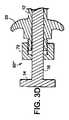
図3A乃至図3Eに移ると、好適実施態ように依ると本発明のアセンブリ10は、手術器具14およびニードル12の相対位置を固定するように使用される第1の固定機構もしくは部材もしくはシステムを含む。図3Aにおいて第1固定システム50は、手術器具14のシャフト15上の刻み目52と、ニードル12もしくはその取手におけるネジ山付き径方向孔55を貫通伸延するネジ54とを含んで示される。手術器具14をニードル12に対して固定することが所望されたとき、ネジ54は(典型的には時計方向に)前記ニードル内へとネジ込まれて、ひとつの刻み目52と係合される。手術器具14を解放することが所望されたとき、ネジ54は、自身が前記刻み目にもはや係合しないように螺着解除される。ネジ54およびネジ山付き径方向孔55の代わりに、手術器具14をニードル12に対して繋止するために、前記ニードル(もしくはニードル取手)における径方向孔を貫通伸延するスプリング負荷ピンが利用され得ることは理解される。 Turning to FIGS. 3A-3E, according to a preferred embodiment, the
図3Bにおいて第2の固定システム50'は、前記手術器具のシャフト15上の径方向溝60と、(ひとつが示される)スプリング・アーム62とシャフト63とを有するクリップ61とを含んで示される。クリップ61のシャフト63は、前記ニードルの壁部、更に好適にはその取手の壁部を貫通伸延すると共に、各スプリング・アーム62はシャフト15上のひとつの径方向溝64に係合する。前記ニードルのシャフト15が該ニードルに対して押し進められまたは引き戻されたとき、各スプリング・アーム62は拡開することでクリップ61を通過するシャフト15の移動を許容する。各スプリング・アーム62が完全に弾性的であれば前記ニードルのシャフト15上に溝は必要とされないことは理解される、と言うのも、各スプリング・アーム62は前記シャフトを所定位置に堅固に保持するからである。 In FIG. 3B, a
図3Cには第3の固定システム50"が示され、該システムは、手術器具14のシャフト15の回りに伸延するプラスチック・ネジ65と、ニードル12の取手もしくはノブ20上に配置された内側ネジ山66とを含んでいる。手術器具14をニードル12に対して固定することが所望されたとき、ネジ65はニードル12のネジ山付き取手もしくはノブニードル20内へと螺着される。取手もしくはノブ20のプラスチック・ネジ65および内側ネジ山66は、ネジ65がネジ山66内へとネジ込まれたときにシャフト15の回りで変形して締め付けることで、ニードル12および手術器具14の夫々の位置を相互に対して固定するように寸法設定される。手術器具14を解放することが所望されたとき、ネジ65は、前記ニードルに対して前記手術器具が移動できるのに十分なだけネジ込みが緩められる(螺着が解除される)。当業者であれば理解されるように、ネジ65は、施術者がトルクを付与するのを助力する(図示しない)ヘッドのような把持部材を有し得る。 In FIG. 3C, a
図3Dは第4の固定システム50"'を示し、該システムは、親指ネジ70と、(図示しない)ネジ山を含むニードル12の取手部分20であって可撓的もしくは可塑的であるという取手部分とを含んでいる。特に、取手部分のネジ山上へと螺着されたときに親指ネジ70は、手術器具14のシャフト15上へと締め付けられ、該手術器具を前記ニードルに対して繋止する。 FIG. 3D shows a
図3Eには第5の固定システム50""が見られ、その場合にニードル取手20'に対してはピン73によりカム部材72が回転的に連結される。第1配向に在るときにカム部材72は、手術器具14のシャフト15の後部15'が無拘束様式で移動することを許容する。図3Eに示された第2配向に在るときにカム部材72は、シャフト15の後部15'に係合し、それをニードル取手20'およびニードル12に対し固定して保持する。図3A乃至図3Dの各固定システムと異なる第5の固定システム50""に加え、ニードル取手20'および手術器具取手24'は、図1および図2および図3A乃至図3Dに示された取手20、24に対して変更されていることは理解される。 FIG. 3E shows a
前記アセンブリはまた好適には、ニードルに対して移動する第2固定部材であって、該ニードルの外側部上に配置されて、患者に対する該ニードルの相対位置を固定するように使用されるという第2固定部材も含んでいる。より詳細には、図4に見られるように、前記第2固定部材は、ニードル12の外側面に係合して該外側面上を摩擦的に摺動可能な軟質プラスチック吸引カップ80であって、患者の腹壁に当接して押圧されることで吸引接続を引き起こし得るという軟質プラスチック吸引カップ80である。所望であれば、ニードル12の外側面は(図示しない)隆起部、鋸歯または溝のような協働部材を備え得ると共に、吸引カップ80は、ニードル12の前記外側面の前記協働部材に係合する(図示しない)対応協働部材であってニードル12に対する該吸引カップ80の箇所を更に強力に固定するという対応協働部材を備え得る。 The assembly is also preferably a second securing member that moves relative to the needle and is disposed on the outer portion of the needle and used to secure the relative position of the needle relative to the patient. It also includes 2 fixing members. More specifically, as seen in FIG. 4, the second securing member is a soft
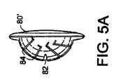
図5Aおよび図5Bに移ると、第2固定アセンブリの第2実施態様は、ニードル12を貫通させて操作し得る頂部基端孔82および複数の差込型溝84を有するプラスチック吸引カップ80'を含んで示される。これにより吸引カップ80'は、ニードル12が患者に対して種々の角度で保持されることができる。 Turning to FIGS. 5A and 5B, a second embodiment of the second securing assembly includes a
吸引カップの代わりに、標準的な器具を使用すると共に、本発明の手術アセンブリを僅かに変更することにより、ニードル12および手術器具14の位置を患者に対して固定することが可能である。故に、図6に見られるように、手術室の台の側部に対してクランプ92により固定される標準的な多重ヘッド式クリップ90が配備される。多重ヘッド式クリップ90は、展性金属ロッド94と、複数のクリップ部材96とを含む。現在において好適な多重ヘッド式クリップの詳細は、2007年1月29日に出願され且つ“手術の間に手術器具を固定するプラットフォーム”と称されると共に同一の譲受人により所有された特許文献3に見られる。 Instead of a suction cup, the position of the
当業者であれば理解されるように、本発明の手術器具14は種々の形態を取り得る。故に図7A乃至図7Gは、本発明の前記手術器具に対する7種類の異なるエンド・エフェクタの代表例を示している。図7Aは、図1および図2に見られるような把持器の詳細図を示している。把持器エンド・エフェクタ101はシャフト15から伸延する2本のアーム102を含み、その各々は約19mm(0.75インチ)長である。各アームはそれらの外周縁にてシャフト15と同一の外郭形状で僅かに丸み付けられ、丸み付けされた各表面は45°〜90°の円弧を形成している。前記アームの(たとえば約4mmの)第1部分104は、それらの静止開き位置において比較的に直線状である。次に、アーム102の中央部分106は、それらが相互から約7mmだけ離間して伸延するまで、相互から離間して角度付けされる(各々、水平から6°〜8°である)。良好なスプリング負荷を提供するために、前記各アームの前記中央部分は、バネ鋼で強化され又はバネ鋼から形成され得る。次に、前記アームの(たとえば約3mmの)先端108は、第1部分104に対して平行に戻し屈曲される。それらの外側面もまた平坦化される。 As will be appreciated by those skilled in the art, the
所望であれば図7Aの前記把持器は、(たとえばレーザもしくはEDM機の使用により)管材の端部を半分に切断して各アームを形成し、第1部分104において各アームの下側部から材料を更に除去してから、第1部分104と中央部分106との交差部および該中央部分106と先端108との交差部にて各アームを屈曲することにより、鋼鉄の中実ロッドもしくは管材から形成され得る。 If desired, the gripper of FIG. 7A may cut each end of the tubing in half (eg, by using a laser or EDM machine) to form each arm, and in the
図7Bは、肺挟持用エンド・エフェクタ111の代表例である。該肺挟持用エンド・エフェクタは、開口115を画成するループ114に終端するアーム112を以てシャフト15から伸延する。図7Bにおいて詳細には示されないが各アーム112は図7Aの把持器のアームと類似している、と言うのも、該アームはそれらの外周縁にてシャフト15と同一の外郭形状で僅かに丸み付けされると共に、該アームは、静止開き位置にて比較的に直線状である第1部分116と、相互から約6mmだけ離間して伸延するまで相互から離間して角度付けされた中央部分118とを含むからである。次に各ループ114は、第1部分116に対して平行に戻し屈曲される。良好なスプリング負荷を提供するために、前記各アームの前記中央部分は、バネ鋼で強化され又はバネ鋼から形成され得る。 FIG. 7B is a typical example of the
図7Cは、1個の把持器122と1個の肺挟持器123とを含む混合エンド・エフェクタ121の代表例を示している。把持器122は図7Aに関して実質的に上述されたものであり、肺挟持器123は図7Bに関して実質的に上述されたものである。 FIG. 7C shows a representative example of a
図7Dは、1個の把持器132と1個のゴム被覆アーム133とを含む非破砕式挟持用エンド・エフェクタ131の代表例である。 FIG. 7D is a representative example of a non-crushing
図7Eは、開創器エンド・エフェクタ141の代表例である。該開創器エンド・エフェクタ141は、静止時には実質的に平坦であるワイヤメッシュ部材143であって、ニードル内へと格納されたときには円弧形状へと屈曲されるというワイヤメッシュ部材143から形成される。 FIG. 7E is a representative example of the
図7Fは、図7Aの把持器と同様の把持器の代表例である。図7Fの把持器エンド・エフェクタ151と図7Aの把持器エンド・エフェクタ101との間の主な相違は、各アーム152は約25mm〜35mm長(1〜1.38インチ)であり、各中央部分156は水平から約50°もしくは25°で相互から離間して角度付けされることである。図7Fに示された先端部分158は、約12mm長であると共に、それらが相互に向けて僅かに角度付けされるように、第1部分154に対する平行を僅かに越えて戻し屈曲される。代替的に前記先端部分は、平行を越えて戻し屈曲される必要は無く、または、全く戻し屈曲される必要はない。各先端部分が戻し屈曲されなければ、該先端部分は相互に対して15mm〜20mmだけ開くように設計され得る。 FIG. 7F is a representative example of a gripper similar to the gripper of FIG. 7A. The main difference between the
図7Gは、ニードル12内の閉じ位置にて示された破砕式把持器161の代表例である。破砕式把持器161は、それが僅かに長寸(約22mm長)であり、且つ、先端部分168は歯部169aを有すると共に、該先端部分は、鈍頭で殆ど半球状の表面を呈するように丸み付けられた前部169bを有する以外は、図7Aの把持器101と同様である。図7Gのエンド・エフェクタ161がニードル12に対して前方に移動されたとき、該エンド・エフェクタは好適には、アーム162の約半分の丈が前記ニードルを越えて伸延するまで、閉じ位置に留まる。故に、以下で論じられるように、手術器具14の前記エンド・エフェクタは、前記ニードルがニードル先端による偶発的な外傷を引き起こすのを阻止するように、前記ニードルに対する閉塞具として作用し得る。 FIG. 7G is a representative example of the crushing
本発明の前記手術アセンブリは、特別なトロカールおよび腹腔鏡器具を用いる代わりに、腹腔鏡式手術の間において使用され得る。特に、(たとえば把持器エンド・エフェクタ111などの)手術器具14を、ニードル12内に部分的に挿入して(すなわちエンド・エフェクタを少なくとも部分的に前記ニードルの内側に引込めて)、選択的に相互に対して(たとえば固定システム50などの)第1固定部材により繋止して、ニードル12は皮膚を穿刺して(たとえば腹部などの)身体内へと前進するように用いられる。(典型的には、既に挿入された観察鏡の案内下で)所望箇所にて、前記ニードルの移動は停止される。(もし、既に繋止されているなら)手術器具14は次に繋止解除され、エンド・エフェクタ111がニードル12を通り越して伸延し、それらの中立応力位置に向けて開くまで前進される。前記ニードルおよび手術器具は次に、前記エンド・エフェクタが伸延して身体内の構造を覆うまで更に前進し得る。次に、前記手術器具を定常状態にして、前記ニードルは該手術器具に対して前進されてエンド・エフェクタ111を強制的に閉じることで、前記構造を堅固に把持する。次に、(たとえばシステム50などの)前記第1固定部材もしくはシステムが使用されることで、前記ニードルを前記手術器具に対して固定することにより、把持された前記構造の離脱が阻止される。所望であれば、前記手術器具が当該ニードル自身に対して固定され且つ前記構造を把持しているという前記ニードルは、(たとえば前記構造を揚動、押圧、または別ように移動するように)体壁に対して操作され得る。前記ニードル(または把持された前記構造)が身体内で所望箇所とされたとき、前記第2固定部材(80など)は前記ニードルに沿い摺動されて患者の皮膚と係合されることで、前記把持器エンド・エフェクタを身体内の所望箇所に固定する。把持された前記構造は任意の時点にて、前記第1固定部材から手術器具を解放させてから前記ニードルを手術器具に対して後方移動させることでエンド・エフェクタが再開できるようにすることにより、解放され得る。(好適には前記手術器具が先ず前記ニードルに対して少なくとも部分的に戻し移動されてエンド・エフェクタが閉じられて)前記手術アセンブリは身体から引き出されることで、多くの場合には瘢痕なしで治癒し得る小寸の穿刺跡が残置される。 The surgical assembly of the present invention can be used during laparoscopic surgery instead of using special trocar and laparoscopic instruments. In particular, a surgical instrument 14 (e.g., grasper end effector 111) may be selectively inserted into the needle 12 (i.e., the end effector is at least partially retracted inside the needle) to selectively The
前記手術アセンブリは小径であることから、前記ニードル・アセンブリを腹部から引抜いても脱気を引き起さず、創傷を閉じるための縫合も必要としないことを銘記されたい。また、前記手術アセンブリは小径であり、トロカール・ポート部材が排除されることから、前記手術アセンブリは手術の間に任意の方向に容易に動かされ得る(すなわち、それは容易に角度付けされ得る)ことも銘記されたい。 Note that because the surgical assembly is small in diameter, pulling out the needle assembly from the abdomen does not cause deaeration and does not require sutures to close the wound. Also, because the surgical assembly is small diameter and the trocar port member is eliminated, the surgical assembly can be easily moved in any direction during surgery (i.e., it can be easily angled). I also want to be noted.
これにより本発明の手術アセンブリは、最小限の個数の部材を以て本発明の前記課題を達成すると共に、高価なトロカール・アセンブリおよび腹腔鏡器具に対して代用され得る。 Thus, the surgical assembly of the present invention accomplishes the above objects of the present invention with a minimum number of members and can be substituted for expensive trocar assemblies and laparoscopic instruments.
本発明の別の見地に依れば、先に言及されたように、前記手術器具のエンド・エフェクタの先端は閉塞具として使用され得る。故に図8A乃至図8Dに見られるように、スプリング193が配備される共に、該スプリングは前記ニードルおよび手術器具の夫々の取手20'、24'に対して連結されることを除き、図3Eおよび図7Gに見られる特性を組み合わせた手術アセンブリが示される。スプリング193は静止位置において、丸み付けされたエンド・エフェクタ161に対し、該エンド・エフェクタがニードル12から外方に伸延するが図8Aに見られるように閉じ位置に留まるという位置を取らせる。この部分的に伸延された位置においてエンド・エフェクタ161は、偶発的なニードル先端による外傷に対する閉塞具もしくは保護具として作用する。図8Bに見られるように、前記手術アセンブリが皮膚を穿刺するように使用されるとき、前記エンド・エフェクタに対しては圧力が付与されることから、該エンド・エフェクタ161は押し戻されてニードルを露出して、前記手術器具は前記ニードルに対して戻し移動されてスプリング193を張る。皮膚が穿刺されて前記ニードルが内腔内へと伸延し、前記エンド・エフェクタに対する圧力が解除されたとき、スプリング193は手術器具を前方へと押圧して図8Aの位置を再び取らせる。エンド・エフェクタ161を延ばして所定構造を把持することが所望されたとき、図8Cに見られるように前記手術器具はニードルに対して前方に押圧されることでスプリング193を圧縮力下に置いてエンド・エフェクタ161を開かせ得る。次に前記エンド・エフェクタは、該エンド・エフェクタをニードルに対して後方に引き戻すことで対象物を覆って閉じられ得るので、前記ニードルは少なくとも部分的に前記エンド・エフェクタを閉じ、スプリング193は部分的に圧縮された位置を取る。前記把持位置(および他の任意の位置)は前記固定部材(たとえばカム72)を用いて任意の時点で繋止され得る。図8Dに見られるように前記エンド・エフェクタを全体的にニードル内へと引込めることが所望されるなら、このことは、前記手術器具を前記ニードルに対して後方に引張ることでスプリング193を再び張力下とすることにより達成され得る。前記手術器具は、前記固定部材を用いて、その位置に繋止され得る。 According to another aspect of the present invention, as mentioned above, the end effector tip of the surgical instrument can be used as an obturator. Thus, as seen in FIGS. 8A-8D, a
図9A乃至図9Dにおいては、ヘルニア修復手術に関する複数の手術アセンブリ10a〜10dの使用法が示される。特に、ヘルニア(開口)290を備えた腹壁200が見られる。ヘルニア290は、(図示しない)腹腔鏡の案内下で腹部内へと挿入されているメッシュ290により修復されるものとする。図9Aに見られるように、本発明に係る4個の手術アセンブリ10a〜10dが腹壁を穿刺するように使用されている。4個の手術アセンブリ10a〜10dは次に、各把持器エンド・エフェクタを夫々のニードルから外方へ移動してメッシュ角隅部を覆って取り囲み、各ニードルを把持器具に対して前進させて前記メッシュを覆って各エンド・エフェクタを閉じて、メッシュ295の角隅領域を把持するように用いられる。次に各ニードルおよび手術器具は(図3A乃至図3Eに関して前記で論じられた第1固定機構もしくはシステムを用いて)好適には相互に対して繋止されて、手術アセンブリ10a〜10dは上方に引張られることでメッシュ295は図9Bに見られるようにヘルニア290の直下に位置される。前記各アセンブリは次に好適には、図4、図5A、図5Bおよび図6に関して前記で論じられたような機構を用いて腹壁に対して所定位置に繋止される。次に、典型的には標準的なトロカール・ポート部材を介して導入された(図示しない)腹腔鏡用ステープラを用いて、前記メッシュは所定位置に綴じられる。次に、各手術器具を繋止解除し、第2固定機構を繋止解除して、各エンド・エフェクタを開かせるために夫々のニードルを戻し移動することにより、前記メッシュは手術アセンブリ10a〜10dから解放され得る。前記メッシュが解放された後、夫々の手術器具のエンド・エフェクタは、少なくとも部分的に夫々のニードル内へと引込められて(且つ、選択的に所定位置に繋止されて)腹部から引抜かれて、図9Cおよび図9Dに見られるように所定位置に綴じられたメッシュ295を残置する。 9A-9D, the use of multiple
当業者であれば、本発明の最少侵襲的な手術アセンブリは、限定的なものとしてで無く、卵管形成術、胃のバイパス、腸の接続、腎臓手術、虫垂切除術、半月軟骨切除術、椎間板切除術などの種々の他の手術処置に対して使用され得ることを理解し得よう。本発明の前記最少侵襲的な手術アセンブリはまた、新生児および小児において特に好適な用途を有すると共に、前記アセンブリおよび方法は動物もしくは死体に対して使用され得る。 For those skilled in the art, the minimally invasive surgical assembly of the present invention is not limited, but includes tubuloplasty, gastric bypass, intestinal connection, kidney surgery, appendectomy, meniscal chondrectomy, It will be appreciated that it can be used for a variety of other surgical procedures such as discectomy. The minimally invasive surgical assembly of the present invention also has particularly suitable applications in neonates and children, and the assembly and method can be used on animals or cadaver.
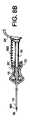
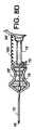
図10乃至図20Bには、本発明の手術アセンブリの別実施態様が示される。図20Aおよび図20Bに見られるように、アセンブリ510は、ニードル512および医療器具514を含んでいる。前記ニードルは、尖状末端側先端518および取手520を有する。前記医療器具は、エンド・エフェクタ522および取手524を有する。図20Aおよび図20Bにはまた、第1固定機構の役割も果たす安全繋止機構550のレバー554が示される。図20Aには、図21A乃至図21Gに関して以下で論じられる第2固定アセンブリ800が見られる。ニードル512、医療器具514および安全繋止機構550の詳細、および、前記安全繋止機構の機能は、図10乃至図20Bに見られる。 10-20B illustrate another embodiment of the surgical assembly of the present invention. As seen in FIGS. 20A and 20B,
図10には、前記医療器具の取手520が見られる。取手524は、施術者の親指を受容するように寸法設定されたループ601と、器具514のシャフトに平行もしくは同軸的な方向に伸延する支柱603とを含む。支柱603は、以下で論じられるように医療器具514の残部に対して取手520を固定するピン607(図16D)を受容するように使用され得る台座605を備え得る。 In FIG. 10, the
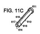
取手524の支柱603は、図11A乃至図11Cに示されたプランジャ610内に受容される。より詳細にはプランジャ610は、頂部管状開口612を画成するヘッド611と、ピン孔613と、底部管状開口614と、停止表面617にて停止する第1溝616を画成するシャフト表面615と、第2溝618と、該溝618に対する停止表面621の画成を助力する平坦化末端部分620と、斜面622とを有する円筒状部材である。頂部開口612は取手520の支柱603を受容すると共に、支柱603の台座605に係合するようにピン孔613内にはピン607(図16D)が挿入される。支柱603が台座605に係合して取手524をプランジャ610に対して軸心的に固定するが該プランジャに対して取手524が回転できるように、ピン孔613は支柱603に対して偏心的である。底部管状開口614は、前記医療器具のシャフト515を受容するように配備される(図11Bにおいてはその頂部のみが示される)。所望であればプランジャ610は、開口612および614を画成する単一の通路を備えた円筒体として形成され得る。 The
プランジャ610のシャフト表面615に画成された溝616および618は、幾つかの機能を実施するように用いられる。以下において更に詳細に記述されるように、溝616は、医療器具514のエンド・エフェクタ522の配向をニードル512の先端の前記斜面に対して固定するように用いられる。溝618の端部における停止表面617もまた、医療器具514がニードル512から完全に離脱するのを阻止する。溝618は、平坦化部分620、停止表面621および斜面622と共にレバー554(図14および図20)と協働して、アセンブリ500に対する安全繋止部および第1固定手段550を提供する。
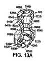
図12A、図12B、図13Aおよび図13Bに移ると、前記ニードルに対する取手520が見られる。取手520は好適には、相互に協働したときに概ねスプール形状の取手を形成する2つの同様の協働部材520A、520Bから形成される。図12Aおよび図12Bに見られるように取手部分520Aは、4個の内部協働支柱622Aと、回転支柱624Aと、スプリング捕捉部もしくは切欠き625と、位置決め舌部626と、プランジャ位置決めリブ628Aと、ニードル・ハブ位置決めリブ629Aと、ニードル・シャフト位置決めリブ630Aとを含む。部分520Aはまた、上側および下側のリブ付き部分632A、634A、および、それらの間の円滑砂時計形状胴部636Aも有し、下側リブ付き部分632Aは前記ニードル・シャフトに対する開口638Aを画成して、上側リブ付き部分634Aは前記プランジャに対する開口639Aを画成している。上側リブ付き部分634Aはまた、停止表面641Aと共に以下で論じられるように、レバー554に対する開口640Aも画成する。図13Aおよび図13Bに見られるように、取手部分520Bは概略的に取手部分520Aに対応すると共に、4個の内部協働支柱受容部622Bと、回転支柱受容部624Bと、プランジャ位置決めリブ628Bと、位置決め用切欠き629B1を備えたニードル・ハブ位置決めリブ629Bと、ニードル・シャフト位置決めリブ630Bとを備えている。部分520Bはまた、上下のリブ付き部分632B、634Bと、それらの間の円滑砂時計形状胴部636Bとを備える外側面も有し、下側リブ付き部分632Bは前記ニードル・シャフトに対する開口638Bを画成して、上側リブ付き部分634Bは前記プランジャに対する開口639Bを画成している。上側リブ付き部分634Bはまた、以下において論じられるように、レバー554のために、停止表面641Bを備えた開口640Bも画成する。 Turning to FIGS. 12A, 12B, 13A and 13B, a
レバー554は、図14、図18Aおよび図18Bに見られ、凹状リブ付き摩擦表面644と、孔647とスプリング649を収容する(図18Aに見られる)スプリング台座648とを画成する本体646と、突端650とを含んでいる。孔647は、レバー554が回転支柱624Aの回りで回転し得るように、該支柱を受容するように寸法設定される。突端650は、角度付き頂面650Aおよび直線状底面650Bを備えた概ね三角形状であり、突端650が前記プランジャの溝618内に入り込むのを許容する第1幅を有している。本体646は、前記取手内への開口であって開口640A、640Bにより形成される開口に嵌合するように寸法設定された第2の更に大寸の幅を有する。以下において論じられるように、前記突端の頂部の近傍における前記本体の丸み付き部分652は、前記アセンブリに対する第1固定部材として用いられる。摩擦表面644は、好適には更に大きな第3の幅を有すると共に、前記取手の協働部材520A、520Bの外側に配置される。
次に図15Aおよび図15Bに移ると、ニードル512の基端部および末端部が見られる。より詳細には、図15Bに見られるように、前記中空ニードルの末端側先端518は斜面形成されて尖っている。図15Aに見られるように中空ニードル512の基端は、ボス656を有するハブ655を備えている。図20Bにより表されるようにハブ655は、取手520に対して所望の配向にてニードル斜面を配向するようにボス656を切欠き629B1内に受容させて、ニードル・ハブ受容リブ629Aおよび629Bにより形成される孔内に捕捉されるべく寸法設定される。所望であれば、前記ニードル・シャフトの基端部は織り目加工されて、施術者に対する特別な把持表面を提供できる。 Turning now to FIGS. 15A and 15B, the proximal and distal ends of the
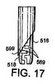
プランジャ610およびレバー554の機能を論ずるに先立ち、本発明の幾つかの付加的な見地に注目すべきである。第1に、スプリング台座648(図18)およびスプリング捕捉部もしくは切欠き625(図12A)は、プランジャ610およびニードル512の垂直軸心に対して突端650が実質的に直交する位置へとスプリング649によりレバー554を時計方向に付勢するように配置される。その位置から時計方向へのレバー554の回転は、前記スプールの上側リブ付き部分の表面641A、641Bにより停止される。前記スプリングに抗する反時計方向へのレバー554の回転は、該レバー554に対して僅かな量の反時計方向の力を付与することで容易に達成され得る。第2に、溝616および618は図11A乃至図11Cにおいて180°離間するとして示されるが、それらは更に好適には90°離間されて、それらの実際の箇所は、レバー554の位置を設定するピン624A(図12A)と、溝616に入り込む舌部626(図12A)との箇所と関連して考慮されるべきである。第3に、ニードル・ハブ655および結節部656(図15A)およびニードル・ハブ受容リブ629A、629Bおよび位置決め用切欠き629B1の使用によるニードル512の配向は好適には、前記エンド・エフェクタが該エンド・エフェクタ自身をニードル512の傾斜先端518に対して遮蔽するように、(プランジャ610に対して固定された)手術器具514の各エンド・エフェクタの配向に対して選択される。特に、本発明のひとつの見地に依れば各エンド・エフェクタ518は図17に示されたように配向され、一方のエンド・エフェクタの完全に典型的には丸み付けされた外側面518は、前記ニードルの傾斜縁部に対して反対側である該傾斜縁部の極限先端599に沿い着座することが好適である。このようにして、前記エンド・エフェクタの表面518は前記ニードルの前記傾斜表面に対して効果的に連続し及び/又はそれを丸み付けし、即ちそれは、前記ニードルの尖端の露出が相当に減少されるように内部遮蔽体として作用する。第4に、以下で論じられるように、(平坦化部分620を含む)プランジャ610の末端部は、それが高度に視認可能であるように赤色または(図示しない)他の顔料で着色され得る。 Before discussing the function of
安全繋止機能および第1固定機能を提供するためのプランジャ610およびレバー554の機能は、図16乃至図19を参照すれば最適に理解される。より詳細には、図16Aは、ニードル先端518が前記エンド・エフェクタにより防護されないように医療器具514がニードル512に対して完全に格納されて前記アセンブリが“装甲”位置に在るときにおけるプランジャ610およびレバー554の位置を示している。図16Aの位置において前記スプールの舌部626(図12A)は、プランジャ610の停止表面617(図11Bおよび図11C)に係合する。同ように、図16Aの位置においてレバー554の突端650は、プランジャ610に対して全く係合しないか、または、該プランジャの斜面形成端部622に係合する。この装甲位置においてアセンブリ510(および、特にニードル512)は、該アセンブリの末端が(たとえば横隔膜などの)体腔内へと通過し得るように、患者の皮膚を穿刺するように使用され得る。同ように、この位置においてプランジャ610の末端部は、ニードル取手520から外方に伸延する。この部分が着色により高度に視認可能とされるならば、施術者に対しては、前記アセンブリが装甲された(すなわち前記ニードルが遮蔽解除された)ことの視認可能な警告が与えられる。 The functions of the
皮膚層を貫通通過した後、前記エンド・エフェクタが前記ニードルの斜面を保護する(防護する)ように手術器具514を前方に移動させることが好適である。図16Bに見られるように、手術器具514のプランジャ610が前記ニードルに対して前方に移動されたとき、前記プランジャの斜面622は、レバー554がスプリング649(図18A)に抗して反時計方向に回転するように、レバー554の角度付き頂面650Aもしくは突端650に当接して作用する。プランジャ610の更なる移動(図16C)により、突端650は該プランジャ610の平坦化末端部分620に入り込む、と言うのも、前記エンド・エフェクタは前記斜面の後側からの出現を開始するからである。図16Dに見られるようにプランジャ610が更に僅かだけ移動されたとき、突端650は溝618に到達し、且つ、該突端の頂部角度付き表面650Aはもはやプランジャ610に接触されない。結果としてスプリング649は、突端650の底面650Bがプランジャ610の軸心に対してほぼ直交して突端650が溝618に入り込むまで、前記レバーを時計方向に回転させる。図16Dに見られるように、もしこの時点において前記ニードルから前記手術器具を後退させる試みが為されたとしても、前記突端の平坦表面650Bが溝618の停止表面621に衝当し、斯かる移動を阻止し、すなわち、前記アセンブリは安全位置に在る。この安全位置において各エンド・エフェクタはニードル512の前記斜面の極限の末端側先端を越えて伸延し、図17に示されたように前記ニードルの先端を防護する。前記ニードルを再装甲するために前記エンド・エフェクタを引込める唯一の様式は、前記レバーを手動で時計方向に強制的に付勢することにより、プランジャ610を僅かだけ前方に押圧し、前記突端が平坦化領域620に対して再び入り込ませることができる。 After passing through the skin layer, it is preferable to move the
前記アセンブリが前記安全位置に一旦到達したなら、操作者は自由に、該アセンブリの作用範囲内で前記プランジャを上下に動かし、(本発明の先行実施態ように関して論じられたように)前記エンド・エフェクタを開閉させる。前記作用範囲は、図16Dの停止位置と、ニードル512の取手520の頂面が手術器具514のプランジャ610のヘッド611に当接する位置とにより定義される。図16Eは、前記レバーの突端650を溝618内に配置し、作用範囲における前記アセンブリを示している。 Once the assembly has reached the safe position, the operator is free to move the plunger up and down within the working range of the assembly (as discussed in connection with the previous embodiment of the invention). Open and close the effector. The operating range is defined by the stop position of FIG. 16D and the position where the top surface of the
前記アセンブリの前記作用範囲の任意の箇所において、器具514およびニードル512の相対位置は固定もしくは繋止され得る。これは、図19Aおよび図19Bに見られるように(突端650および溝618より広幅である)突端650の頂部の近傍における前記レバーの本体646の丸み付き部分652が溝618の回りでプランジャ614のシャフト表面615に対して摩擦係合するまで、スプリング力に抗してレバー554を回転させることにより達成される。この係合の摩擦力は、スプリング649が丸み付き部分652を表面615から自動的には離脱させないようにスプリング649のスプリング力より大きく、好適には、前記ニードルに対する前記器具の偶発的な移動を阻止するに十分なほど大きく設定される。この配置構成によれば、前記ニードルと比較して前記エンド・エフェクタに対して付与された大きな引張荷重によって前記繋止機構の滑動し得、大きな圧縮荷重によって繋止解除を引き起こし得る。通常の利用において、前記ニードルから前記器具を繋止解除することが所望されるなら、レバー554は、前記アセンブリがその作用範囲において使用され得るように反時計方向に回転され得る。本発明の他の実施態様と同ように、身体からのアセンブリ510の取出しは、前記エンド・エフェクタを開いてまたは閉じて行われ得る。 At any point in the working range of the assembly, the relative position of the
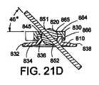
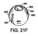
次に図21A乃至図21Gに移ると、手術アセンブリを患者の身体に対して固定する第2固定手段の第3実施態様が見られる。第2固定手段800は3個の部材を含んでいる:基部810、圧縮可能ボール820および起動本体830。図21A、図21Dおよび図21Gに最適に見られる第2固定手段800の基部810は基本的にワッシャであり、該ワッシャは、接着層834(および不図示の剥離可能な保護紙層)が適用され得る平坦底面832と、截頭円錐形状の中央開口836(図21Dを参照)と、指用把持部841および中央リング844を画成する頂面838とを有する。リング844は、前記ボールを受容する僅かにテーパ付けされた内側面845(図21D)と、3個の別体的な外側傾斜部846とを画成し、該外側傾斜部は、該リング内へと凹状形成されると共に、該リングの頂面847にて開始し、該外側傾斜部が頂部ワッシャ表面838に到達するまで、該外側傾斜部がリングの回りで時計方向に伸延するにつれて下降する。図21Gにおいて最適に見られるように、各傾斜部846は前記リングの頂面847上の夫々の開口に対して僅かに凹状形成されることで、以下に説明される目的で小寸棚部848を形成する。 Turning now to FIGS. 21A-21G, a third embodiment of second securing means for securing the surgical assembly to the patient's body is seen. The second securing means 800 includes three members: a base 810, a
ボール820は好適には中空のプラスチック・ボールであり、且つ、該ボールは、手術アセンブリ510のニードル・シャフトを緊密に受容するように寸法設定されて対置された円形開口851、852と、該開口851、852により規定される軸心の方向に向け、開口852から約120°伸延する複数のスリット853とを備える。各スリット853の故に前記ボールは、該ボールに対して円周方向の力が付与されると、各スリット853の間に夫々形成された葉状部854が相互に向けて移動するように圧縮可能である。図21A乃至図21Dに最適に見られるようにボール820は、各スリット853が下方に伸延するようにリング844内で配向される。 The
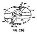
起動本体830は、図21Aおよび図21Eに最適に見られると共に、実効的に、伸延アーム862を備えたキャップ860から成る。キャップ860は中央開口865を備えた頂壁864を有し、該開口を通りボール820の頂部が伸延し得る。キャップ860はまた、係合フィンガ868を画成する切欠を備えた側壁866も有している。係合フィンガ868は夫々、リング844の傾斜部846に入り込むべく寸法設定されたボス869を有している。図21Eに最適に見られるように、内方に向く前記ボスは傾斜もしくは斜面形成される。 The
組立て時に、ボール820は起動本体830と基部810との間に載置されて、各ボス869は棚部848を越えて付勢されて傾斜部846と係合される。この位置において前記起動本体のキャップ860の側壁866の底部は前記ワッシャの頂面838に対して離間されて(図21Dを参照)、前記ボールはリング844および中央開口865により案内されて自由に回転する。故に、前記手術アセンブリのシャフトが前記ボールの円形開口851、852を貫通して挿入されたとき、該シャフトは相当な移動の自由度を有し、キャップ860の中央開口865および前記基部の截頭円錐形状の中央開口836のサイズにより制限されるだけである。好適には第2固定手段800は前記アセンブリに対し、全ての方向において垂直に対して少なくとも45°の移動の自由度を提供する。但し、(典型的には親指および人差し指によりアーム862および841を一体的に握り込むことで)起動本体830が基部810に対して時計方向に回転されたとき、ボス869は傾斜部846を下り、本体830を基部810に近付けて引張る。ボール820は前記リング内で下方に移動し得ないことから、各中央開口865は前記ボールに対して円周方向の力を提供する(すなわち、それは前記ボールを圧縮する)ことで、葉状部854を内方に付勢し、前記手術アセンブリのシャフトに対して摩擦を付与する。結果として、前記シャフトがボール820内の所定位置に繋止されるだけでなく、該ボールは固定手段800内における該ボールの回転配向に関して固定される。ボール820および前記シャフトは、(典型的には他方のアーム862、841を一体的に握り込むことで)本体830を前記基部に対して反時計方向に回転することにより解除され得る。但し、本体830は基部810から揚動離脱し得ない、と言うのも、棚部848が停止部として作用するからである。 During assembly, the
本明細書においては、最少侵襲的な手術アセンブリおよびその使用方法の幾つかの実施態様が記述かつ図示された。本発明の特定実施態様が記述されたが、本発明がそれらに限定されることは意図されない、と言うのも、本発明は当業界が許容するのと同様の有効範囲において広範囲であり且つ本明細書もそのように解釈されるべきことが意図されるからである。したがって、前記ニードルおよび手術器具を作成する特定の材料が開示されたが、他の材料も使用され得ることは理解される。加えて、前記ニードルに対して前記手術器具を固定するために前記固定部材およびシステムが開示されたが、他の機構が使用され得ることは理解される。たとえば、限定ではないが、ラッチ/捕捉部システムが使用され得る。同ように、手術アセンブリの箇所を患者に対して固定する特定の固定部材およびシステムが記述されたが、そのための他の機構が使用され得ることは理解される。更に、前記手術器具に対しては把持器、肺挟持器などのような特定のエンド・エフェクタが記述されたが、(限定的なものとしてで無く)切開器、ステープラ、剪刀、吸引/潅流器、クランプ、生検鉗子などのような種々のエンド・エフェクタを備えた器具が同ように使用され得ることは理解される。同様に、前記エンド・エフェクタのアームは等しい長さとされる必要はない。更に、前記手術器具およびニードルは直線状であると示されたが、それらは小径なので、それらはユーザにより一体的に屈曲され得、または、一方もしくは両方に屈曲部(弧状部)が形成され得る。更に、前記手術器具および前記ニードルの取手に関して特定の構成が記述されて開示されたが、他の構成も同様に使用され得ることは理解される。これに加え、前記ニードルは特定サイズであって、一定角度を備えた尖端を有すると記述されたが、他のサイズのニードルが使用され得ると共に尖端は異なる角度とされ得ることは理解される。したがって、当業者であれば、提供されて権利請求された本発明の趣旨および有効範囲から逸脱せずに更に別の変更が本発明に対して為され得ることを理解し得よう。 In this specification, several embodiments of a minimally invasive surgical assembly and method of use have been described and illustrated. While particular embodiments of the present invention have been described, it is not intended that the invention be limited thereto, since the present invention is broad and within the same scope as allowed by the industry. This is because the specification is intended to be interpreted as such. Thus, while specific materials for making the needle and surgical instrument have been disclosed, it is understood that other materials may be used. In addition, although the fixation member and system have been disclosed to secure the surgical instrument relative to the needle, it will be appreciated that other mechanisms may be used. For example, but not limited to, a latch / capture system can be used. Similarly, although specific fixation members and systems have been described that secure the location of the surgical assembly to the patient, it will be understood that other mechanisms may be used therefor. In addition, specific end effectors such as graspers, pulmonary clamps, etc. have been described for the surgical instruments, but (but not limited to) incisors, staplers, scissors, suction / perfusion devices It will be appreciated that instruments with various end effectors such as clamps, biopsy forceps and the like may be used as well. Similarly, the end effector arms need not be of equal length. Furthermore, although the surgical instruments and needles have been shown to be straight, they are small in diameter so they can be bent together by the user, or a bend (arc) can be formed on one or both . Further, while specific configurations have been described and disclosed with respect to the surgical instrument and the needle handle, it is understood that other configurations may be used as well. In addition, although the needle has been described as being of a specific size and having a tip with a constant angle, it is understood that other sizes of needles can be used and the tip can be at a different angle. Accordingly, one of ordinary skill in the art appreciates that further modifications can be made to the present invention without departing from the spirit and scope of the invention as provided and claimed.
なお、 本出願は、2006年3月13日に出願された米国仮出願第60/781,556号、2006年10月10日に出願された米国仮出願第60/828,916号、および、米国特許出願第11/420,927号の優先権を主張するものであり、それらの全ては言及したことにより全体的に本明細書中に援用される。 Note that this application is a U.S. provisional application No. 60 / 781,556 filed on March 13, 2006, a U.S. provisional application No. 60 / 828,916 filed on October 10, 2006, and a U.S. patent application no. No. 11 / 420,927, all of which are hereby incorporated by reference in their entirety.
Claims (33)
Translated fromJapaneseb)前記中空ニードルを貫通して伸延するシャフトを有する手術器具を具備し、
該手術器具は、前記中空ニードルに対して移動可能であり、かつ、
該手術器具は、前記シャフトの端部に備わる複数のエンド・エフェクタを有し、
各エンド・エフェクタは前記中空ニードルから外方に伸延したとき、前記各エンド・エフェクタは互いに自動的に開くように開き位置に付勢されていて、
前記中空ニードルが伸延して前記エンド・エフェクタを覆ったときには、前記エンド・エフェクタは自動的に閉じ位置へ押し込まれる、
手術アセンブリ。a) a hollow needle having an outer diameter of 3 mm or less and a pointed end;
b) comprising a surgical instrument having a shaft extending through the hollow needle;
The surgical instrument is movable relative to the hollow needle; and
The surgical instrument has a plurality of end effectors provided at the end of the shaft,
When each end effector extends outwardly from the hollow needle, the end effectors are biased to the open position to automatically open to each other;
When the hollow needle is distracted to cover the end effector, the end effector is automatically pushed into the closed position;
Surgical assembly.
或いは、
前記中空ニードルはプラスチック部材を備えた取手を有すると共に、前記第1ネジ部材は前記取手上の外部ネジ山であり、前記第2ネジ部材は、前記プラスチック部材を変形させるために前記外部ネジ山に係合する中空ネジである、請求項6記載の手術アセンブリ。The hollow needle has a handle, the first screw member is an inner thread on the handle, and the second screw member is a plastic hollow screw extending around the shaft,
Or
The hollow needle has a handle with a plastic member, the first screw member is an external thread on the handle, and the second screw member is on the external thread to deform the plastic member. The surgical assembly of claim 6, wherein the surgical assembly is an engaging hollow screw.
前記シャフトと、
前記シャフトの末端および当該エンド・エフェクタの基端で前記シャフトに堅固に連結された前記スプリングで付勢されたエンド・エフェクタと、
前記シャフトを前記エンド・エフェクタと共に移動させる取手もしくはノブとから成る、請求項1記載の手術アセンブリ。The surgical instrument is basically:
The shaft;
A spring-biased end effector rigidly coupled to the shaft at the distal end of the shaft and at the proximal end of the end effector;
The surgical assembly of claim 1, comprising a handle or knob that moves the shaft with the end effector.
前記中空ニードルと、
前記手術器具と、
前記手術器具を前記ニードルに固定する手段とから成る、請求項17記載の手術アセンブリ。The surgical assembly is basically
The hollow needle;
The surgical instrument;
The surgical assembly of claim 17, comprising means for securing the surgical instrument to the needle.
前記中空ニードルと、
前記手術器具と、
前記手術器具を前記ニードルに固定する手段と、
前記中空ニードルを、前記尖状末端が挿入載置される体腔に固定する手段とから成る、請求項17記載の手術アセンブリ。The surgical assembly is basically
The hollow needle;
The surgical instrument;
Means for securing the surgical instrument to the needle;
The surgical assembly of claim 17, comprising means for securing the hollow needle to a body cavity into which the pointed end is inserted.
前記安全機構は、前記エンド・エフェクタが前記中空ニードル内へと完全に引込められるのを阻止する停止部を含む、請求項1記載の手術アセンブリ。The surgical assembly is an operating range of the surgical instrument relative to the hollow needle, in which the end effector always establishes an operating range that extends past the pointed end of the hollow needle. A mechanism,
The surgical assembly of claim 1, wherein the safety mechanism includes a stop that prevents the end effector from being fully retracted into the hollow needle.
前記表面構造は、前記突出部を受容するように寸法設定された溝であって前記停止部において終端する溝を含む、請求項22記載の手術アセンブリ。The lever is spring loaded and includes a protrusion;
23. The surgical assembly of claim 22, wherein the surface structure includes a groove dimensioned to receive the protrusion and terminating at the stop.
前記各エンド・エフェクタが前記中空ニードルから部分的に外方に伸延するときに、前記各エンド・エフェクタの内の第1のエンド・エフェクタの外側面の方が第2の表面の外側面よりも多く露出されるように前記医療器具は前記ニードルに固定して配向される、請求項1記載の手術アセンブリ。The hollow needle is beveled to the tip, and each end effector has an outer surface and mutually opposed inner gripping surfaces;
When each end effector extends partially outward from the hollow needle, the outer surface of the first end effector of each end effector is more than the outer surface of the second surface. The surgical assembly according to claim 1, wherein the medical device is fixedly oriented to the needle so as to be exposed to a large amount.
b)前記各エンド・エフェクタを閉じ位置として、前記中空ニードルの前記尖状末端を用いて前記手術アセンブリの末端部を患者の内腔内へと挿入する段階と、
c)前記手術器具を前記ニードルに対して前方に移動することで、前記各エンド・エフェクタを前記ニードルから外方に伸延させ且つ該各エンド・エフェクタを相互に対して自動的に開かせる段階と、
d)前記内腔内において対象物を覆うべく前記エンド・エフェクタを移動する段階と、
e)前記ニードルに対して前記ニードルを前方に移動することで、前記対象物を覆って前記エンド・エフェクタを閉じさせる段階とを備えて成る、
手術方法。a) a surgical instrument having a hollow needle having an outer diameter of 3 mm or less and a pointed end, and a shaft extending through the hollow needle, the surgical instrument being movable relative to the hollow needle; Procuring a surgical assembly having a surgical instrument comprising an end effector at an end of the shaft and biased to an open position;
b) inserting the distal end of the surgical assembly into the patient's lumen using the pointed end of the hollow needle with each end effector in a closed position;
c) moving the surgical instrument forward relative to the needle to extend the end effectors outwardly from the needle and automatically open the end effectors relative to each other; ,
d) moving the end effector to cover the object within the lumen;
e) moving the needle forward with respect to the needle to cover the object and close the end effector.
Surgery method.
各手術アセンブリに対し、ニードルおよび手術器具を一体的に移動することにより前記対象物を押し進め又は引き戻す段階を更に備えて成る、請求項27記載の方法。Repeating steps a) -e) with a plurality of substantially identical surgical assemblies;
28. The method of claim 27, further comprising, for each surgical assembly, pushing or pulling the object back by moving the needle and surgical instrument together.
前記内腔内において対象物を覆うべく前記エンド・エフェクタを移動する段階、および、前記ニードルに対して前記ニードルを前方に移動して、前記対象物を覆って前記エンド・エフェクタを閉じさせる段階は、前記動作範囲内で行われる、請求項27記載の方法。The surgical assembly establishes an operating range of the surgical instrument relative to the hollow needle, wherein the end effector always extends past the pointed end of the hollow needle. Further comprising a safety mechanism, the safety mechanism including a stop to prevent the end effector from being fully retracted into the hollow needle;
Moving the end effector to cover the object within the lumen, and moving the needle forward relative to the needle to cover the object and close the end effector; 28. The method of claim 27, wherein the method is performed within the operating range.
Applications Claiming Priority (7)
| Application Number | Priority Date | Filing Date | Title |
|---|---|---|---|
| US78155606P | 2006-03-13 | 2006-03-13 | |
| US60/781,556 | 2006-03-13 | ||
| US11/420,927US7766937B2 (en) | 2006-03-13 | 2006-05-30 | Minimally invasive surgical assembly and methods |
| US11/420,927 | 2006-05-30 | ||
| US82891606P | 2006-10-10 | 2006-10-10 | |
| US60/828,916 | 2006-10-10 | ||
| PCT/US2007/063883WO2007106813A2 (en) | 2006-03-13 | 2007-03-13 | Minimally invasive surgical assembly and methods |
Publications (3)
| Publication Number | Publication Date |
|---|---|
| JP2009529983Atrue JP2009529983A (en) | 2009-08-27 |
| JP2009529983A5 JP2009529983A5 (en) | 2010-04-22 |
| JP5443158B2 JP5443158B2 (en) | 2014-03-19 |
Family
ID=38510235
Family Applications (1)
| Application Number | Title | Priority Date | Filing Date |
|---|---|---|---|
| JP2009500585AActiveJP5443158B2 (en) | 2006-03-13 | 2007-03-13 | Minimally invasive surgical assembly and method |
Country Status (8)
| Country | Link |
|---|---|
| US (3) | US9492187B2 (en) |
| EP (1) | EP1996090A2 (en) |
| JP (1) | JP5443158B2 (en) |
| KR (1) | KR101332173B1 (en) |
| AU (1) | AU2007226579B2 (en) |
| BR (1) | BRPI0709615A2 (en) |
| MX (1) | MX2008011789A (en) |
| WO (1) | WO2007106813A2 (en) |
Cited By (11)
| Publication number | Priority date | Publication date | Assignee | Title |
|---|---|---|---|---|
| JP2011224300A (en)* | 2010-04-18 | 2011-11-10 | Shu Nakamura | Grasping forceps for endoscopic surgery |
| JP2013541966A (en)* | 2010-06-29 | 2013-11-21 | イエール ユニバーシティー | Tissue retractor assembly |
| JP2014531936A (en)* | 2011-09-30 | 2014-12-04 | ザ・トラスティーズ・オブ・コロンビア・ユニバーシティ・イン・ザ・シティ・オブ・ニューヨーク | Systems and devices for bone reduction and articulation |
| JP2015217234A (en)* | 2014-05-21 | 2015-12-07 | 株式会社八光 | Treatment instrument for minimally invasive surgery |
| WO2016002328A1 (en)* | 2014-07-01 | 2016-01-07 | オリンパス株式会社 | Tissue grasping tool |
| US9463039B2 (en) | 2013-01-18 | 2016-10-11 | Olympus Corporation | Endoscopic device |
| JP2017038637A (en)* | 2015-08-17 | 2017-02-23 | 株式会社八光 | Fixing plate of medical treatment appliance |
| JP2017527331A (en)* | 2014-07-15 | 2017-09-21 | テレフレックス メディカル インコーポレイテッド | Replaceable surgical access port assembly |
| US9782197B2 (en) | 2014-08-22 | 2017-10-10 | Olympus Corporation | Tissue grasping device |
| US10856901B2 (en) | 2013-09-18 | 2020-12-08 | Teleflex Medical Incorporated | Exchanger surgical access port assembly and methods of use |
| US11627975B2 (en) | 2013-04-16 | 2023-04-18 | Teleflex Medical Incorporated | Needlescopic instrument with reusable handle and detachable needle assembly |
Families Citing this family (75)
| Publication number | Priority date | Publication date | Assignee | Title |
|---|---|---|---|---|
| US8182501B2 (en) | 2004-02-27 | 2012-05-22 | Ethicon Endo-Surgery, Inc. | Ultrasonic surgical shears and method for sealing a blood vessel using same |
| US20050283163A1 (en)* | 2004-06-04 | 2005-12-22 | Valdemar Portney | Intraocular lens implanting instrument |
| US20060079879A1 (en) | 2004-10-08 | 2006-04-13 | Faller Craig N | Actuation mechanism for use with an ultrasonic surgical instrument |
| US20070191713A1 (en) | 2005-10-14 | 2007-08-16 | Eichmann Stephen E | Ultrasonic device for cutting and coagulating |
| US7621930B2 (en) | 2006-01-20 | 2009-11-24 | Ethicon Endo-Surgery, Inc. | Ultrasound medical instrument having a medical ultrasonic blade |
| US7766937B2 (en) | 2006-03-13 | 2010-08-03 | Mini-Lap Technologies, Inc. | Minimally invasive surgical assembly and methods |
| US8133255B2 (en)* | 2006-03-13 | 2012-03-13 | Mini-Lap Technologies, Inc. | Minimally invasive surgical assembly and methods |
| US7976554B2 (en) | 2006-04-19 | 2011-07-12 | Vibrynt, Inc. | Devices, tools and methods for performing minimally invasive abdominal surgical procedures |
| US8585733B2 (en) | 2006-04-19 | 2013-11-19 | Vibrynt, Inc | Devices, tools and methods for performing minimally invasive abdominal surgical procedures |
| US8142461B2 (en) | 2007-03-22 | 2012-03-27 | Ethicon Endo-Surgery, Inc. | Surgical instruments |
| US8057498B2 (en) | 2007-11-30 | 2011-11-15 | Ethicon Endo-Surgery, Inc. | Ultrasonic surgical instrument blades |
| US8911460B2 (en) | 2007-03-22 | 2014-12-16 | Ethicon Endo-Surgery, Inc. | Ultrasonic surgical instruments |
| US9138129B2 (en)* | 2007-06-13 | 2015-09-22 | Intuitive Surgical Operations, Inc. | Method and system for moving a plurality of articulated instruments in tandem back towards an entry guide |
| US8523889B2 (en) | 2007-07-27 | 2013-09-03 | Ethicon Endo-Surgery, Inc. | Ultrasonic end effectors with increased active length |
| US8808319B2 (en) | 2007-07-27 | 2014-08-19 | Ethicon Endo-Surgery, Inc. | Surgical instruments |
| US9044261B2 (en) | 2007-07-31 | 2015-06-02 | Ethicon Endo-Surgery, Inc. | Temperature controlled ultrasonic surgical instruments |
| US8512365B2 (en) | 2007-07-31 | 2013-08-20 | Ethicon Endo-Surgery, Inc. | Surgical instruments |
| US8430898B2 (en) | 2007-07-31 | 2013-04-30 | Ethicon Endo-Surgery, Inc. | Ultrasonic surgical instruments |
| EP2217157A2 (en) | 2007-10-05 | 2010-08-18 | Ethicon Endo-Surgery, Inc. | Ergonomic surgical instruments |
| US10010339B2 (en) | 2007-11-30 | 2018-07-03 | Ethicon Llc | Ultrasonic surgical blades |
| US9597095B2 (en)* | 2009-05-15 | 2017-03-21 | Globus Medical, Inc | Screw guide and tissue retractor instrument |
| US9700339B2 (en) | 2009-05-20 | 2017-07-11 | Ethicon Endo-Surgery, Inc. | Coupling arrangements and methods for attaching tools to ultrasonic surgical instruments |
| CA2776937C (en)* | 2009-10-07 | 2018-05-29 | Umc Utrecht Holding B.V. | Holding device for holding a manually operated medical device |
| US9326757B2 (en) | 2009-12-31 | 2016-05-03 | Teleflex Medical Incorporated | Surgical instruments for laparoscopic aspiration and retraction |
| US8951272B2 (en) | 2010-02-11 | 2015-02-10 | Ethicon Endo-Surgery, Inc. | Seal arrangements for ultrasonically powered surgical instruments |
| US8486096B2 (en) | 2010-02-11 | 2013-07-16 | Ethicon Endo-Surgery, Inc. | Dual purpose surgical instrument for cutting and coagulating tissue |
| US10098631B2 (en) | 2010-09-10 | 2018-10-16 | Pivot Medical, Inc. | Method and apparatus for passing suture through tissue |
| CA2813597C (en) | 2010-09-10 | 2019-09-03 | Pivot Medical, Inc. | Method and apparatus for passing suture through tissue |
| WO2015066620A1 (en) | 2010-09-10 | 2015-05-07 | Pivot Medical, Inc. | Method and apparatus for passing suture through tissue |
| US20130012984A1 (en)* | 2011-07-07 | 2013-01-10 | Warsaw Orthopedic, Inc. | Surgical instrument for grasping an elongated member |
| EP2747796B8 (en)* | 2011-08-25 | 2018-12-26 | Universität Zürich | A device for repair surgery of cylindrical organs, particularly ruptured tendons |
| EP2757963A1 (en)* | 2011-09-23 | 2014-07-30 | Surgical Perspectives SAS | Clip for organ retraction during minimally invasive surgery |
| US9314362B2 (en) | 2012-01-08 | 2016-04-19 | Vibrynt, Inc. | Methods, instruments and devices for extragastric reduction of stomach volume |
| US8382775B1 (en) | 2012-01-08 | 2013-02-26 | Vibrynt, Inc. | Methods, instruments and devices for extragastric reduction of stomach volume |
| US8529555B1 (en)* | 2012-04-19 | 2013-09-10 | Microline Surgical, Inc. | Instrument tip assembly having self-threading back hub |
| US9820768B2 (en) | 2012-06-29 | 2017-11-21 | Ethicon Llc | Ultrasonic surgical instruments with control mechanisms |
| US10226273B2 (en) | 2013-03-14 | 2019-03-12 | Ethicon Llc | Mechanical fasteners for use with surgical energy devices |
| WO2014141226A1 (en) | 2013-03-15 | 2014-09-18 | National University Of Ireland | A device suitable for removing matter from inside the lumen and the wall of a body lumen |
| JP6201035B2 (en)* | 2013-04-16 | 2017-09-20 | テレフレックス メディカル インコーポレイテッド | Minimally invasive surgical assembly and method |
| US9848879B2 (en) | 2013-08-02 | 2017-12-26 | Covidien Lp | Devices, systems, and methods for wound closure |
| US9510823B2 (en) | 2013-08-02 | 2016-12-06 | Covidien Lp | Devices, systems, and methods for wound closure |
| US10258324B2 (en) | 2013-08-02 | 2019-04-16 | Covidien Lp | Devices, systems, and methods for providing surgical access and facilitating closure of surgical access openings |
| US10070851B2 (en) | 2013-08-02 | 2018-09-11 | Covidien Lp | Devices, systems, and methods for wound closure |
| WO2015038549A2 (en)* | 2013-09-11 | 2015-03-19 | Gimmi Gmbh | Endoscopic surgical instruments and related methods |
| EP3079600B1 (en) | 2013-12-09 | 2020-03-04 | Teleflex Medical Incorporated | Sliding suture grasper |
| GB2521229A (en) | 2013-12-16 | 2015-06-17 | Ethicon Endo Surgery Inc | Medical device |
| US20170245889A1 (en)* | 2014-09-26 | 2017-08-31 | Vanderbilt University | Movement dampening system for a surgical tool |
| EP3017775A1 (en) | 2014-11-07 | 2016-05-11 | National University of Ireland, Galway | A thrombectomy device |
| EP4563066A2 (en)* | 2015-05-27 | 2025-06-04 | Olympus Corporation | Device for endoscope |
| US11020140B2 (en) | 2015-06-17 | 2021-06-01 | Cilag Gmbh International | Ultrasonic surgical blade for use with ultrasonic surgical instruments |
| US10357303B2 (en) | 2015-06-30 | 2019-07-23 | Ethicon Llc | Translatable outer tube for sealing using shielded lap chole dissector |
| DE102015114264A1 (en)* | 2015-08-27 | 2017-03-02 | Karl Storz Gmbh & Co. Kg | Micro-invasive medical instrument |
| HK1210569A2 (en)* | 2015-12-17 | 2016-04-22 | 太津治有限公司 | Surgical device |
| US10245064B2 (en) | 2016-07-12 | 2019-04-02 | Ethicon Llc | Ultrasonic surgical instrument with piezoelectric central lumen transducer |
| US10893883B2 (en) | 2016-07-13 | 2021-01-19 | Ethicon Llc | Ultrasonic assembly for use with ultrasonic surgical instruments |
| USD847990S1 (en) | 2016-08-16 | 2019-05-07 | Ethicon Llc | Surgical instrument |
| US10952759B2 (en) | 2016-08-25 | 2021-03-23 | Ethicon Llc | Tissue loading of a surgical instrument |
| US10736649B2 (en) | 2016-08-25 | 2020-08-11 | Ethicon Llc | Electrical and thermal connections for ultrasonic transducer |
| US10603064B2 (en) | 2016-11-28 | 2020-03-31 | Ethicon Llc | Ultrasonic transducer |
| US10820920B2 (en) | 2017-07-05 | 2020-11-03 | Ethicon Llc | Reusable ultrasonic medical devices and methods of their use |
| US11071828B2 (en)* | 2018-01-26 | 2021-07-27 | Treble Innovations, Llc | Colored seal system, method, and apparatus |
| TWI734958B (en) | 2018-03-19 | 2021-08-01 | 日商泰爾茂股份有限公司 | Puncture needle and catheter assembly |
| US11129609B2 (en) | 2018-04-24 | 2021-09-28 | Covidien Lp | Devices, systems, and methods for providing surgical access and facilitating closure of surgical access openings |
| US11213288B2 (en) | 2018-05-02 | 2022-01-04 | Covidien Lp | Port site closure instrument |
| US11234690B2 (en) | 2018-05-02 | 2022-02-01 | Covidien Lp | Method and device for closing a port site incision |
| EP3787526B1 (en)* | 2018-05-04 | 2023-04-19 | Arch Day Design, LLC | Suture passing device |
| US11278274B2 (en) | 2018-05-04 | 2022-03-22 | Arch Day Design, Llc | Suture passing device |
| US11583269B2 (en) | 2018-05-04 | 2023-02-21 | Arch Day Design, Llc | Suture passing device |
| DE202018104602U1 (en)* | 2018-08-10 | 2018-08-17 | Lohmann & Rauscher Gmbh | protective sleeve |
| DE102019201833A1 (en)* | 2019-02-13 | 2020-08-13 | Geuder Ag | Handheld ophthalmic device |
| US11246586B2 (en) | 2019-08-20 | 2022-02-15 | Arch Day Design, Llc | Instrument to manipulate and pass suture |
| US10945553B1 (en)* | 2019-10-04 | 2021-03-16 | Gregory A. Fletcher, Sr. | Device and method for measuring and dispensing customizable amounts of material |
| CN111616834B (en)* | 2020-05-11 | 2025-01-28 | 山东大学第二医院 | A 3D printed laryngeal mold insertion device |
| KR102476456B1 (en)* | 2020-06-19 | 2022-12-12 | 주식회사 킴스바이오 | Ureter Access Sheath with Length-adjustable structure |
| CN113317846B (en)* | 2021-07-13 | 2022-12-02 | 上海长征医院 | A suction gun-shaped rongeur for laminectomy and decompression |
Citations (7)
| Publication number | Priority date | Publication date | Assignee | Title |
|---|---|---|---|---|
| US4174715A (en)* | 1977-03-28 | 1979-11-20 | Hasson Harrith M | Multi-pronged laparoscopy forceps |
| JPH055105U (en)* | 1991-07-04 | 1993-01-26 | オリンパス光学工業株式会社 | Operation part of treatment tool for endoscope |
| JPH067368A (en)* | 1992-05-01 | 1994-01-18 | Vance Prod Inc | Percutaneous tissue storing device |
| JPH08505307A (en)* | 1993-07-26 | 1996-06-11 | イノベーシブ・ディバイセス・インコーポレーテッド | Suture gripping device |
| JPH10151138A (en)* | 1996-11-25 | 1998-06-09 | Olympus Optical Co Ltd | Peritoneal puncture needle |
| US20030130693A1 (en)* | 1999-05-18 | 2003-07-10 | Levin John M. | Laparoscopic/thorascopic insertion caps |
| US6616683B1 (en)* | 2000-05-02 | 2003-09-09 | Duke University | Method of making miniaturized surgical forceps |
Family Cites Families (47)
| Publication number | Priority date | Publication date | Assignee | Title |
|---|---|---|---|---|
| US3817251A (en) | 1972-10-04 | 1974-06-18 | H Hasson | Laparoscope cannula |
| US3844291A (en) | 1973-04-26 | 1974-10-29 | G Moen | Grip device |
| US3961632A (en) | 1974-12-13 | 1976-06-08 | Moossun Mohamed H | Stomach intubation and catheter placement system |
| US4570642A (en)* | 1983-09-23 | 1986-02-18 | Daig Corporation | Endocardial extendable screw-in lead |
| US4723547A (en)* | 1985-05-07 | 1988-02-09 | C. R. Bard, Inc. | Anti-obesity balloon placement system |
| US4890615B1 (en)* | 1987-11-05 | 1993-11-16 | Linvatec Corporation | Arthroscopic suturing instrument |
| US5176697A (en) | 1989-04-06 | 1993-01-05 | Hasson Harrith M | Laparoscopic cannula |
| US5330497A (en) | 1989-11-22 | 1994-07-19 | Dexide, Inc. | Locking trocar sleeve |
| US6099550A (en)* | 1989-12-05 | 2000-08-08 | Yoon; Inbae | Surgical instrument having jaws and an operating channel and method for use thereof |
| US5073169A (en) | 1990-10-02 | 1991-12-17 | Steve Raiken | Trocar support |
| US5147316A (en) | 1990-11-19 | 1992-09-15 | Castillenti Thomas A | Laparoscopic trocar with self-locking port sleeve |
| US5224954A (en) | 1991-02-19 | 1993-07-06 | Dexide, Inc. | Combination surgical trocar cannula and rake assembly |
| US5201742A (en) | 1991-04-16 | 1993-04-13 | Hasson Harrith M | Support jig for a surgical instrument |
| US5176643A (en)* | 1991-04-29 | 1993-01-05 | George C. Kramer | System and method for rapid vascular drug delivery |
| US5258005A (en)* | 1991-12-13 | 1993-11-02 | Unisurge, Inc. | Atraumatic grasping device for laparoscopic surgery |
| US5290276A (en) | 1992-02-06 | 1994-03-01 | Sewell Jr Frank | Rotatable laparoscopic puncturing instrument |
| US5542432A (en) | 1992-02-18 | 1996-08-06 | Symbiosis Corporation | Endoscopic multiple sample bioptome |
| US5222973A (en) | 1992-03-09 | 1993-06-29 | Sharpe Endosurgical Corporation | Endoscopic grasping tool surgical instrument |
| US5375588A (en) | 1992-08-17 | 1994-12-27 | Yoon; Inbae | Method and apparatus for use in endoscopic procedures |
| US5658272A (en) | 1992-09-15 | 1997-08-19 | Hasson; Harrith M. | Surgical instrument support and method of using the same |
| US5281237A (en)* | 1992-09-25 | 1994-01-25 | Gimpelson Richard J | Surgical stitching device and method of use |
| JP3180219B2 (en) | 1993-07-09 | 2001-06-25 | ニプロ株式会社 | Trocar |
| US5658298A (en)* | 1993-11-09 | 1997-08-19 | Inamed Development Company | Laparoscopic tool |
| US5354283A (en)* | 1994-01-07 | 1994-10-11 | Little Rapids Corporation | Trocar retention apparatus |
| US5601571A (en)* | 1994-05-17 | 1997-02-11 | Moss; Gerald | Surgical fastener implantation device |
| US5634918A (en) | 1994-10-26 | 1997-06-03 | Grieshaber & Co. Ag Schaffhausen | Ophthalmic surgical instrument |
| US5573530A (en)* | 1994-12-15 | 1996-11-12 | Cabot Technology Corporation | Handle for a surgical instrument including a manually actuated brake |
| US5653716A (en)* | 1994-12-29 | 1997-08-05 | Acufex Microsurgical, Inc. | Suture manipulating instrument with grasping members |
| US5626597A (en) | 1995-02-21 | 1997-05-06 | United States Surgical Corporation | Percutaneous introducer |
| US5857999A (en)* | 1995-05-05 | 1999-01-12 | Imagyn Medical Technologies, Inc. | Small diameter introducer for laparoscopic instruments |
| US5964740A (en)* | 1996-07-09 | 1999-10-12 | Asahi Kogaku Kogyo Kabushiki Kaisha | Treatment accessory for an endoscope |
| AU7518096A (en) | 1995-10-23 | 1997-05-15 | Johns Hopkins University, The | Surgical instrument |
| US5814043A (en)* | 1996-09-06 | 1998-09-29 | Mentor Ophthalmics, Inc. | Bipolar electrosurgical device |
| US5971940A (en)* | 1998-02-20 | 1999-10-26 | Scimed Life Systems, Inc. | Surgical instrument with locking feature, split distal housing, and sharpened jaws |
| US20010045575A1 (en) | 1998-05-01 | 2001-11-29 | Mark Ashby | Device and method for facilitating hemostasis of a biopsy tract |
| US6391046B1 (en) | 2000-04-14 | 2002-05-21 | Duke University | Omni-actuatable hand-held surgical instruments |
| US6500170B2 (en)* | 2000-10-11 | 2002-12-31 | Popcab, Llc | Instrument stabilizer for through-the-port surgery |
| US6855156B2 (en) | 2000-10-19 | 2005-02-15 | Grieshaber & Co. Ag Schaffhausen | Ophthalmic microsurgical instrument |
| JP4431815B2 (en) | 2001-03-27 | 2010-03-17 | シーアールエス ホールディングス,インコーポレイテッド | Ultra-strength precipitation hardened stainless steel and long strip made from the same steel |
| US6945984B2 (en) | 2001-08-23 | 2005-09-20 | Alcon Grieshaber Ag | Micro surgical instrument |
| US6860894B1 (en) | 2002-02-15 | 2005-03-01 | Gregory R. Pittman | Laparoscopic lifter apparatus and method |
| AU2003215196A1 (en) | 2002-02-15 | 2003-09-09 | Taut, Inc. | Anchoring assembly for a medical instrument |
| US6740277B2 (en)* | 2002-04-24 | 2004-05-25 | Becton Dickinson And Company | Process of making a catheter |
| US7025775B2 (en)* | 2003-05-15 | 2006-04-11 | Applied Medical Resources Corporation | Surgical instrument with removable shaft apparatus and method |
| DE602004018342D1 (en) | 2003-08-26 | 2009-01-22 | Zimmer Spine Inc | ACCESS SYSTEMS FOR MINIMALLY INVASIVE SURGERY |
| US6945894B2 (en) | 2003-10-29 | 2005-09-20 | General Motors Corporation | Two range electrically variable power transmission |
| US20050283163A1 (en) | 2004-06-04 | 2005-12-22 | Valdemar Portney | Intraocular lens implanting instrument |
- 2007
- 2007-03-13AUAU2007226579Apatent/AU2007226579B2/enactiveActive
- 2007-03-13KRKR1020087024831Apatent/KR101332173B1/enactiveActive
- 2007-03-13WOPCT/US2007/063883patent/WO2007106813A2/enactiveApplication Filing
- 2007-03-13USUS11/685,522patent/US9492187B2/enactiveActive
- 2007-03-13BRBRPI0709615-1Apatent/BRPI0709615A2/ennot_activeIP Right Cessation
- 2007-03-13MXMX2008011789Apatent/MX2008011789A/enactiveIP Right Grant
- 2007-03-13EPEP07758435Apatent/EP1996090A2/ennot_activeWithdrawn
- 2007-03-13JPJP2009500585Apatent/JP5443158B2/enactiveActive
- 2016
- 2016-11-07USUS15/344,739patent/US11109875B2/enactiveActive
- 2016-11-08USUS15/345,716patent/US10166038B2/enactiveActive
Patent Citations (7)
| Publication number | Priority date | Publication date | Assignee | Title |
|---|---|---|---|---|
| US4174715A (en)* | 1977-03-28 | 1979-11-20 | Hasson Harrith M | Multi-pronged laparoscopy forceps |
| JPH055105U (en)* | 1991-07-04 | 1993-01-26 | オリンパス光学工業株式会社 | Operation part of treatment tool for endoscope |
| JPH067368A (en)* | 1992-05-01 | 1994-01-18 | Vance Prod Inc | Percutaneous tissue storing device |
| JPH08505307A (en)* | 1993-07-26 | 1996-06-11 | イノベーシブ・ディバイセス・インコーポレーテッド | Suture gripping device |
| JPH10151138A (en)* | 1996-11-25 | 1998-06-09 | Olympus Optical Co Ltd | Peritoneal puncture needle |
| US20030130693A1 (en)* | 1999-05-18 | 2003-07-10 | Levin John M. | Laparoscopic/thorascopic insertion caps |
| US6616683B1 (en)* | 2000-05-02 | 2003-09-09 | Duke University | Method of making miniaturized surgical forceps |
Cited By (15)
| Publication number | Priority date | Publication date | Assignee | Title |
|---|---|---|---|---|
| JP2011224300A (en)* | 2010-04-18 | 2011-11-10 | Shu Nakamura | Grasping forceps for endoscopic surgery |
| JP2013541966A (en)* | 2010-06-29 | 2013-11-21 | イエール ユニバーシティー | Tissue retractor assembly |
| JP2014531936A (en)* | 2011-09-30 | 2014-12-04 | ザ・トラスティーズ・オブ・コロンビア・ユニバーシティ・イン・ザ・シティ・オブ・ニューヨーク | Systems and devices for bone reduction and articulation |
| US9463039B2 (en) | 2013-01-18 | 2016-10-11 | Olympus Corporation | Endoscopic device |
| US11627975B2 (en) | 2013-04-16 | 2023-04-18 | Teleflex Medical Incorporated | Needlescopic instrument with reusable handle and detachable needle assembly |
| US10856901B2 (en) | 2013-09-18 | 2020-12-08 | Teleflex Medical Incorporated | Exchanger surgical access port assembly and methods of use |
| JP2015217234A (en)* | 2014-05-21 | 2015-12-07 | 株式会社八光 | Treatment instrument for minimally invasive surgery |
| US10092307B2 (en) | 2014-07-01 | 2018-10-09 | Olympus Corporation | Tissue grasping tool |
| JP5914779B1 (en)* | 2014-07-01 | 2016-05-11 | オリンパス株式会社 | Tissue grasping device |
| WO2016002328A1 (en)* | 2014-07-01 | 2016-01-07 | オリンパス株式会社 | Tissue grasping tool |
| JP2017527331A (en)* | 2014-07-15 | 2017-09-21 | テレフレックス メディカル インコーポレイテッド | Replaceable surgical access port assembly |
| US10368907B2 (en) | 2014-07-15 | 2019-08-06 | Teleflex Medical Incorporated | Exchanger surgical access port and methods of use |
| US11627984B2 (en) | 2014-07-15 | 2023-04-18 | Teleflex Medical Incorporated | Exchanger surgical access port and methods of use |
| US9782197B2 (en) | 2014-08-22 | 2017-10-10 | Olympus Corporation | Tissue grasping device |
| JP2017038637A (en)* | 2015-08-17 | 2017-02-23 | 株式会社八光 | Fixing plate of medical treatment appliance |
Also Published As
| Publication number | Publication date |
|---|---|
| US20070250112A1 (en) | 2007-10-25 |
| AU2007226579B2 (en) | 2013-03-14 |
| WO2007106813A3 (en) | 2008-02-07 |
| US9492187B2 (en) | 2016-11-15 |
| JP5443158B2 (en) | 2014-03-19 |
| KR101332173B1 (en) | 2013-11-25 |
| KR20090013169A (en) | 2009-02-04 |
| US20170049464A1 (en) | 2017-02-23 |
| BRPI0709615A2 (en) | 2011-07-19 |
| US20170049465A1 (en) | 2017-02-23 |
| EP1996090A2 (en) | 2008-12-03 |
| US11109875B2 (en) | 2021-09-07 |
| WO2007106813A2 (en) | 2007-09-20 |
| AU2007226579A1 (en) | 2007-09-20 |
| US10166038B2 (en) | 2019-01-01 |
| MX2008011789A (en) | 2009-01-22 |
Similar Documents
| Publication | Publication Date | Title |
|---|---|---|
| JP5443158B2 (en) | Minimally invasive surgical assembly and method | |
| US9486238B2 (en) | Minimally invasive surgical clamps, assemblies and methods | |
| US7766937B2 (en) | Minimally invasive surgical assembly and methods | |
| US8133255B2 (en) | Minimally invasive surgical assembly and methods | |
| CN101478923B (en) | Minimally invasive surgical assembly and methods | |
| AU742708B2 (en) | Systems, methods, and instruments for minimally invasive surgery | |
| US6165184A (en) | Systems methods and instruments for minimally invasive surgery | |
| CA2569878C (en) | Surgical closure instrument and methods | |
| CA2600237C (en) | Rotating knob locking mechanism for surgical stapling device | |
| JPH06217987A (en) | Nonexternal wound type endoscope device | |
| EP2223658B1 (en) | Multi-purpose surgical instrument | |
| EP1545320B1 (en) | Multi-purpose surgical instrument | |
| AU2013206659B2 (en) | Rotating knob locking mechanism for surgical stapling device |
Legal Events
| Date | Code | Title | Description |
|---|---|---|---|
| A521 | Request for written amendment filed | Free format text:JAPANESE INTERMEDIATE CODE: A523 Effective date:20100308 | |
| A621 | Written request for application examination | Free format text:JAPANESE INTERMEDIATE CODE: A621 Effective date:20100308 | |
| A131 | Notification of reasons for refusal | Free format text:JAPANESE INTERMEDIATE CODE: A131 Effective date:20120313 | |
| A977 | Report on retrieval | Free format text:JAPANESE INTERMEDIATE CODE: A971007 Effective date:20120315 | |
| A601 | Written request for extension of time | Free format text:JAPANESE INTERMEDIATE CODE: A601 Effective date:20120612 | |
| A602 | Written permission of extension of time | Free format text:JAPANESE INTERMEDIATE CODE: A602 Effective date:20120619 | |
| A521 | Request for written amendment filed | Free format text:JAPANESE INTERMEDIATE CODE: A523 Effective date:20120913 | |
| A131 | Notification of reasons for refusal | Free format text:JAPANESE INTERMEDIATE CODE: A131 Effective date:20130319 | |
| TRDD | Decision of grant or rejection written | ||
| A01 | Written decision to grant a patent or to grant a registration (utility model) | Free format text:JAPANESE INTERMEDIATE CODE: A01 Effective date:20131119 | |
| A61 | First payment of annual fees (during grant procedure) | Free format text:JAPANESE INTERMEDIATE CODE: A61 Effective date:20131219 | |
| R150 | Certificate of patent or registration of utility model | Ref document number:5443158 Country of ref document:JP Free format text:JAPANESE INTERMEDIATE CODE: R150 Free format text:JAPANESE INTERMEDIATE CODE: R150 | |
| R250 | Receipt of annual fees | Free format text:JAPANESE INTERMEDIATE CODE: R250 | |
| R250 | Receipt of annual fees | Free format text:JAPANESE INTERMEDIATE CODE: R250 | |
| R250 | Receipt of annual fees | Free format text:JAPANESE INTERMEDIATE CODE: R250 | |
| R250 | Receipt of annual fees | Free format text:JAPANESE INTERMEDIATE CODE: R250 | |
| R250 | Receipt of annual fees | Free format text:JAPANESE INTERMEDIATE CODE: R250 | |
| R250 | Receipt of annual fees | Free format text:JAPANESE INTERMEDIATE CODE: R250 | |
| R250 | Receipt of annual fees | Free format text:JAPANESE INTERMEDIATE CODE: R250 | |
| R250 | Receipt of annual fees | Free format text:JAPANESE INTERMEDIATE CODE: R250 | |
| R250 | Receipt of annual fees | Free format text:JAPANESE INTERMEDIATE CODE: R250 |