JP2009529390A - Device for processing body tissue - Google Patents
Device for processing body tissueDownload PDFInfo
- Publication number
- JP2009529390A JP2009529390AJP2008558663AJP2008558663AJP2009529390AJP 2009529390 AJP2009529390 AJP 2009529390AJP 2008558663 AJP2008558663 AJP 2008558663AJP 2008558663 AJP2008558663 AJP 2008558663AJP 2009529390 AJP2009529390 AJP 2009529390A
- Authority
- JP
- Japan
- Prior art keywords
- tubular member
- distal end
- insertion tube
- proximal
- base structure
- Prior art date
- Legal status (The legal status is an assumption and is not a legal conclusion. Google has not performed a legal analysis and makes no representation as to the accuracy of the status listed.)
- Pending
Links
- 238000012545processingMethods0.000titleabstractdescription5
- 238000003780insertionMethods0.000claimsabstractdescription73
- 230000037431insertionEffects0.000claimsabstractdescription73
- 230000007246mechanismEffects0.000claimsabstractdescription52
- 230000033001locomotionEffects0.000claimsabstractdescription44
- 230000005540biological transmissionEffects0.000claimsdescription20
- 238000012546transferMethods0.000claimsdescription5
- 238000007629laparoscopic insertionMethods0.000abstractdescription10
- 238000001839endoscopyMethods0.000description6
- 230000008901benefitEffects0.000description4
- 238000002357laparoscopic surgeryMethods0.000description4
- 241001465754MetazoaSpecies0.000description3
- 230000008878couplingEffects0.000description3
- 238000010168coupling processMethods0.000description3
- 238000005859coupling reactionMethods0.000description3
- 238000001356surgical procedureMethods0.000description3
- 238000010586diagramMethods0.000description2
- 239000013307optical fiberSubstances0.000description2
- 238000011084recoveryMethods0.000description2
- 229940035674anestheticsDrugs0.000description1
- 230000003466anti-cipated effectEffects0.000description1
- 230000001934delayEffects0.000description1
- 230000001419dependent effectEffects0.000description1
- 238000011161developmentMethods0.000description1
- 238000002405diagnostic procedureMethods0.000description1
- 230000000694effectsEffects0.000description1
- 239000013013elastic materialSubstances0.000description1
- 210000003238esophagusAnatomy0.000description1
- 238000011010flushing procedureMethods0.000description1
- 239000003193general anesthetic agentSubstances0.000description1
- 208000015181infectious diseaseDiseases0.000description1
- 230000003993interactionEffects0.000description1
- 230000001788irregularEffects0.000description1
- 239000000463materialSubstances0.000description1
- 238000000034methodMethods0.000description1
- 238000002324minimally invasive surgeryMethods0.000description1
- 210000000664rectumAnatomy0.000description1
- 230000037390scarringEffects0.000description1
- 238000000926separation methodMethods0.000description1
- 238000009423ventilationMethods0.000description1
- 210000001835visceraAnatomy0.000description1
Images


Classifications
- A—HUMAN NECESSITIES
- A61—MEDICAL OR VETERINARY SCIENCE; HYGIENE
- A61B—DIAGNOSIS; SURGERY; IDENTIFICATION
- A61B17/00—Surgical instruments, devices or methods
- A61B17/28—Surgical forceps
- A61B17/29—Forceps for use in minimally invasive surgery
- A—HUMAN NECESSITIES
- A61—MEDICAL OR VETERINARY SCIENCE; HYGIENE
- A61B—DIAGNOSIS; SURGERY; IDENTIFICATION
- A61B1/00—Instruments for performing medical examinations of the interior of cavities or tubes of the body by visual or photographical inspection, e.g. endoscopes; Illuminating arrangements therefor
- A61B1/00131—Accessories for endoscopes
- A61B1/0014—Fastening element for attaching accessories to the outside of an endoscope, e.g. clips, clamps or bands
- A—HUMAN NECESSITIES
- A61—MEDICAL OR VETERINARY SCIENCE; HYGIENE
- A61B—DIAGNOSIS; SURGERY; IDENTIFICATION
- A61B1/00—Instruments for performing medical examinations of the interior of cavities or tubes of the body by visual or photographical inspection, e.g. endoscopes; Illuminating arrangements therefor
- A61B1/012—Instruments for performing medical examinations of the interior of cavities or tubes of the body by visual or photographical inspection, e.g. endoscopes; Illuminating arrangements therefor characterised by internal passages or accessories therefor
- A61B1/018—Instruments for performing medical examinations of the interior of cavities or tubes of the body by visual or photographical inspection, e.g. endoscopes; Illuminating arrangements therefor characterised by internal passages or accessories therefor for receiving instruments
- A—HUMAN NECESSITIES
- A61—MEDICAL OR VETERINARY SCIENCE; HYGIENE
- A61B—DIAGNOSIS; SURGERY; IDENTIFICATION
- A61B17/00—Surgical instruments, devices or methods
- A61B17/00234—Surgical instruments, devices or methods for minimally invasive surgery
- A61B2017/00238—Type of minimally invasive operation
- A61B2017/00278—Transorgan operations, e.g. transgastric
- A—HUMAN NECESSITIES
- A61—MEDICAL OR VETERINARY SCIENCE; HYGIENE
- A61B—DIAGNOSIS; SURGERY; IDENTIFICATION
- A61B17/00—Surgical instruments, devices or methods
- A61B17/34—Trocars; Puncturing needles
- A61B17/3417—Details of tips or shafts, e.g. grooves, expandable, bendable; Multiple coaxial sliding cannulas, e.g. for dilating
- A61B17/3421—Cannulas
- A61B2017/3445—Cannulas used as instrument channel for multiple instruments
- A61B2017/3447—Linked multiple cannulas
- A—HUMAN NECESSITIES
- A61—MEDICAL OR VETERINARY SCIENCE; HYGIENE
- A61B—DIAGNOSIS; SURGERY; IDENTIFICATION
- A61B90/00—Instruments, implements or accessories specially adapted for surgery or diagnosis and not covered by any of the groups A61B1/00 - A61B50/00, e.g. for luxation treatment or for protecting wound edges
- A61B90/50—Supports for surgical instruments, e.g. articulated arms
Landscapes
- Health & Medical Sciences (AREA)
- Life Sciences & Earth Sciences (AREA)
- Surgery (AREA)
- General Health & Medical Sciences (AREA)
- Public Health (AREA)
- Veterinary Medicine (AREA)
- Nuclear Medicine, Radiotherapy & Molecular Imaging (AREA)
- Animal Behavior & Ethology (AREA)
- Molecular Biology (AREA)
- Engineering & Computer Science (AREA)
- Biomedical Technology (AREA)
- Heart & Thoracic Surgery (AREA)
- Medical Informatics (AREA)
- Biophysics (AREA)
- Radiology & Medical Imaging (AREA)
- Physics & Mathematics (AREA)
- Pathology (AREA)
- Optics & Photonics (AREA)
- Ophthalmology & Optometry (AREA)
- Endoscopes (AREA)
- Surgical Instruments (AREA)
- Control And Other Processes For Unpacking Of Materials (AREA)
- Treatments For Attaching Organic Compounds To Fibrous Goods (AREA)
Abstract
Translated fromJapaneseDescription
Translated fromJapanese本発明は、概して、内視鏡検査および腹腔鏡手術に用いるための医療装置、詳細には、内視鏡検査または腹腔鏡手術によって体組織を処理するための装置に関する。 The present invention relates generally to medical devices for use in endoscopy and laparoscopic surgery, and more particularly to devices for processing body tissue by endoscopy or laparoscopic surgery.
内視鏡検査は、例えば、食道や直腸などの体の天然の開口部または導管を介してヒトまたは動物の体内に到達して観察する最小侵襲性処置である。このタイプのいわゆる管腔アクセス(endoluminal access)により、外科医または医師は、開口部または体の導管の内部、または、それらを通してアクセスできる体内の器官の組織を観察し、かつ/または治療することができる。上記の介入は、従来の切開外科手術で行うこともできるが、内視鏡検査は、痛み、リスク、および瘢痕が少なく、患者の回復が早い。 Endoscopy is a minimally invasive procedure that reaches and observes the body of a human or animal, for example, through a natural opening or conduit in the body such as the esophagus or rectum. This type of so-called endoluminal access allows the surgeon or physician to observe and / or treat tissue in the internal organs of the opening or body conduits accessible through them. . Although the above interventions can be performed with conventional open surgery, endoscopy has less pain, risk, and scarring and results in faster patient recovery.
内視鏡検査は、典型的には、開口部の中へ所望の内部位置まで挿入される遠位端部を備えた小径の挿入チューブを含む内視鏡によって行われる。遠位端部からの軸方向の観察が可能となるように、遠位端部で終端する光ファイバーが挿入チューブ内に延びている。内視鏡の遠位端部に近い内部位置のイメージが、外科医が観察できるようにビデオモニタに伝達される。内視鏡の近位部分に配列された制御ハンドルにより、視野の方向付けができ、場合によっては、内視鏡にとって必要な可能性のある吸引、換気、または水洗装置の作動を調節することができる。 Endoscopy is typically performed with an endoscope that includes a small diameter insertion tube with a distal end that is inserted into an opening to a desired internal position. An optical fiber that terminates at the distal end extends into the insertion tube so that axial viewing from the distal end is possible. An image of the internal location near the distal end of the endoscope is transmitted to the video monitor for viewing by the surgeon. A control handle arranged in the proximal part of the endoscope allows the orientation of the field of view and in some cases adjusts the operation of the suction, ventilation or flushing devices that may be necessary for the endoscope it can.
内視鏡は、体内の位置で治療を行うために用いることができるため、一部の内視鏡は、用具または手術器具を送ることができるチャネルを備えている。通常は、このようなチャネルは、挿入チューブの長さに沿ってその遠位端部まで延びており、手術器具が遠位端部から軸方向に突き出てしまう。このため、手術器具の運動は、内視鏡の遠位端部の向き設定軸に対する軸方向運動および回転運動に制限され、このタイプの装置で行うことができる複雑かつ様々な外科処置や診断処置に対して様々な制限が課されている。 Because endoscopes can be used to perform treatment at a location in the body, some endoscopes include a channel through which tools or surgical instruments can be delivered. Typically, such a channel extends along the length of the insertion tube to its distal end, causing the surgical instrument to protrude axially from the distal end. Thus, the movement of the surgical instrument is limited to axial and rotational movements relative to the orientation axis of the distal end of the endoscope, and complex and varied surgical and diagnostic procedures that can be performed with this type of device. There are various restrictions on
上記制限の一部は、腹腔鏡手術によって解消することができ、この手術では、腹腔鏡を挿入する前に行われる、小さな切開部を介したヒトまたは動物の体内へのアクセスが達成される。腹腔鏡は、切開部から所望の内部位置まで挿入される遠位端部を備えた小径の挿入チューブを含む。遠位端部から軸方向の観察が可能となるように、遠位端部で終端する光ファイバーが、挿入チューブ内に延びている。腹腔鏡の遠位端部に近い内部位置のイメージが、外科医が観察できるようにビデオモニタに伝達される。切開部を通るアクセスは、体の天然の導管によるアクセス方法よりも直接的で、短く、かつ直線的である。このため、内視鏡の挿入チューブよりも短く、硬質、かつ直線状の腹腔鏡挿入チューブを用いることができる。 Some of the limitations can be overcome by laparoscopic surgery, which achieves access to the human or animal body through a small incision made prior to inserting the laparoscope. The laparoscope includes a small diameter insertion tube with a distal end that is inserted from the incision to the desired internal location. An optical fiber that terminates at the distal end extends into the insertion tube so that axial viewing from the distal end is possible. An image of the internal location near the distal end of the laparoscope is transmitted to the video monitor for viewing by the surgeon. Access through the incision is more direct, shorter and straighter than the access method through the body's natural conduit. For this reason, it is possible to use a laparoscope insertion tube that is shorter and harder than the insertion tube of the endoscope.
体の天然の導管の存在および形状に制約されない腹腔鏡手術により、多数の切開部を介した別の手術器具の挿入が可能となり、手術器具の適切な位置付けおよび向き設定(orientation)により、様々な方向の手術器具の位置付けが可能となる。この利点は、手術器具の向き設定および運動の制限を解消できるが、多数の切開部による高い侵襲性の代償としてのみ得られるものである。実際、手術器具のアクセス通路を作ることが必須であり、これにより、一般的な麻酔剤を必要とする「トロカール」針の使用、合併症および感染のリスク、および患者の回復時間の遅れなどが伴う。したがって、本発明の目的は、内視鏡検査の典型的な利点、すなわち侵襲性がさほどなく、体の内部深くにある場所に達するのに適切であるという利点を放棄することなく、手術器具の向き設定および位置付けの自由度を高めることができる、上記の最小侵襲性処置を行うための装置を提供することにある。 Laparoscopic surgery, which is not constrained by the presence and shape of the body's natural conduits, allows the insertion of another surgical instrument through multiple incisions, and the proper positioning and orientation of the surgical instrument allows a variety of Allows positioning of surgical instruments in the direction. This advantage can eliminate surgical instrument orientation and movement limitations, but only at the cost of a high invasiveness with multiple incisions. In fact, it is essential to create an access path for surgical instruments, which includes the use of “trocar” needles that require common anesthetics, the risk of complications and infections, and delays in patient recovery time. Accompany. Therefore, the object of the present invention is that of the surgical instrument without giving up the typical advantages of endoscopy, i.e. less invasive and appropriate to reach a place deep inside the body. An object of the present invention is to provide a device for performing the above-mentioned minimally invasive treatment, which can increase the degree of freedom of orientation setting and positioning.
本発明のさらなる目的は、厄介な取付け手段を必要とせずに従来の内視鏡および腹腔鏡と共に用いることができことにより、信頼性が高く、堅牢で、使用が容易であり、またコスト効率の良い、組織を処理するための装置を提供することにある。 A further object of the present invention is that it can be used with conventional endoscopes and laparoscopes without the need for cumbersome attachment means, thereby being reliable, robust, easy to use and cost effective. It is to provide a good device for processing tissue.
このような目的および他の目的は、体組織を処理するための装置によって果たされ、この装置は、
ベース構造と、
近位端部、および、手術器具を支持するための座部を定めている向き設定可能な遠位端部を有する少なくとも1つの管状部材であって、前記管状部材は、ベース構造に接続されている、管状部材と、
管状部材の前記遠位端部の向きを設定してこの遠位端部を所定の動作配置にするのに適した、作動機構であって、前記作動機構は、ベース構造に接続されている、作動機構と、
作動機構および管状部材が内視鏡または腹腔鏡の挿入チューブの外側に配列されるように、挿入チューブの遠位端部部分にベース構造を接続するための手段と、
を含み、
前記管状部材は、ベース構造に対する、管状部材の作動部分の運動が向き設定可能な端部の前記向き設定を伴うように、作動機構と相互作用する。These and other objectives are served by a device for treating body tissue,
The base structure,
At least one tubular member having a proximal end and an orientable distal end defining a seat for supporting a surgical instrument, said tubular member being connected to a base structure A tubular member;
An actuation mechanism suitable for setting the orientation of the distal end of the tubular member to place the distal end in a predetermined operational arrangement, the actuation mechanism being connected to a base structure; An operating mechanism;
Means for connecting the base structure to the distal end portion of the insertion tube such that the actuation mechanism and the tubular member are arranged outside the insertion tube of the endoscope or laparoscope;
Including
The tubular member interacts with an actuating mechanism such that movement of the actuating portion of the tubular member relative to the base structure is accompanied by the orientation setting of the directionable end.
本発明による装置の特徴により、手術器具自体のためのさらなるアクセス路を必要とすることなく、1つの内視鏡または腹腔鏡を用いて、挿入チューブの内部構造に支障を与えることなく、挿入チューブに対して手術器具の、広い角度の向き設定を行うことが可能である。 Due to the features of the device according to the present invention, the insertion tube can be used with one endoscope or laparoscope without disturbing the internal structure of the insertion tube without the need for further access paths for the surgical instrument itself. In contrast, it is possible to set the orientation of the surgical instrument at a wide angle.
本発明および有利な実施形態のさらなる概念の発展が、従属請求項の目的である。 The development of further concepts of the invention and advantageous embodiments is the object of the dependent claims.
本発明では、管状部材の近位端部からその向き設定可能な遠位端部への手術器具の移送を可能にし、かつ挿入チューブを引き抜いて再挿入する必要なく介入中の手術器具の交換を可能にする管状部材内のチャネルを提供することがいかに有利であるかに注目した。 The present invention allows for the transfer of surgical instruments from the proximal end of the tubular member to its orientable distal end and allows replacement of surgical instruments during intervention without having to pull out and reinsert the insertion tube. It was noted how advantageous it would be to provide a channel in the tubular member that would allow.
本発明のさらなる態様によると、管状部材は、作動機構と管状部材の近位端部との間に配列された、少なくとも1つの伝達部分を含み、この伝達部分は、実質的に硬質の管状ロッドを形成する。この管状ロッドの剛性により、挿入チューブに管状部材を固定するために特別なガイドを見越しておく必要がなく、従って、従来の内視鏡または腹腔鏡の典型的な構造に支障を与えずに、作動機構を作動させることが可能である。 According to a further aspect of the invention, the tubular member includes at least one transmission portion arranged between the actuation mechanism and the proximal end of the tubular member, the transmission portion comprising a substantially rigid tubular rod. Form. Due to the rigidity of this tubular rod, it is not necessary to foresee special guides to secure the tubular member to the insertion tube, and thus without disturbing the typical structure of a conventional endoscope or laparoscope, The actuating mechanism can be actuated.
別法では、管状部材のガイドされた伝達部分は、例えば内視鏡などの可撓性挿入チューブの変形形状に従うことができるように実質的に可撓性とすることができる。 Alternatively, the guided transmission portion of the tubular member can be substantially flexible so that it can follow a deformed shape of a flexible insertion tube, such as an endoscope.
本発明のさらなる態様によると、作動機構は、管状部材に接続された、この管状部材とは別個の関節フレームを含む。これにより、有利なことに、管状部材の手術器具の移送機能および支持機能とは別個の作動機構の作動機能が可能となっている。 According to a further aspect of the invention, the actuating mechanism includes a joint frame separate from the tubular member connected to the tubular member. This advantageously allows an actuating function of the actuating mechanism that is separate from the function of transferring and supporting the surgical instrument of the tubular member.
本発明のさらなる態様によると、関節フレームは、ベース構造の固定ヒンジ部分に回転可能に接続された第1の端部、および、この固定ヒンジ部分に対して、より近位側のベース構造のガイド部分にスライド可能に接続された第2の端部を含み、管状部材の向き設定可能な遠位端部は、関節フレームの変形によって、向き設定可能な端部の向き設定がなされるように、関節フレームに接続されている。作動機構の運動を制約するこの配置により、向き設定可能な遠位部分の特に安定した支持が得られ、手術器具の向き設定の調節によって手術器具の軸方向の移動が同時にもたらされることはない。 According to a further aspect of the invention, the articulation frame comprises a first end rotatably connected to the fixed hinge portion of the base structure and a guide of the base structure more proximal to the fixed hinge portion. A second end that is slidably connected to the portion, wherein the distal end of the tubular member is orientable such that the orientation of the endurable end is configured by deformation of the articulated frame; Connected to the joint frame. This arrangement that constrains the movement of the actuating mechanism provides a particularly stable support for the orientable distal portion, and adjustment of the orientation of the surgical instrument does not result in simultaneous axial movement of the surgical instrument.
本発明およびその利点をより良く理解できるように、添付の図面を参照して、限定目的ではない幾つかの実施形態を以下に記載する。 In order that the invention and its advantages may be better understood, some non-limiting embodiments are described below with reference to the accompanying drawings.
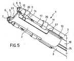
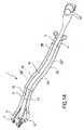
図1を参照すると、体組織を処理するための装置全体が、参照符号1として示されている。装置1は、ベース構造2と、近位端部4および向き設定可能な遠位端部5を有する少なくとも1つの管状部材3を含む。遠位端部5は、例えば把持器7などの手術器具を支持するための座部6を定めている。管状部材3は、作動機構、具体的には関節フレーム8によってベース構造2に接続されている。この作動機構は、管状部材3の遠位端部5の向きを設定して特定の動作配置にするのに適しており、具体的には、ベース構造2の長手方向軸(後述する挿入チューブ10の遠位端部部分9の長手方向軸R10に一致する)に対して遠位端部5を傾斜方向または横断方向に向き設定するのに適している。作動機構8はまた、ベース構造2に接続されている。 Referring to FIG. 1, the entire device for treating body tissue is shown as
ベース構造2は、作動機構8および管状部材3を挿入チューブ10の外側に配列できるように、内視鏡または腹腔鏡の挿入チューブ10の遠位端部部分9に接続されるか、または適当な接続手段を介して接続されることもできる。管状部材3は、ベース構造2に対する管状部材3の作動部分11の運動によって向き設定可能な遠位端部5を上記のように向き設定するように、作動機構8に接続されている。 The
既に述べたように、一実施形態では、作動機構は、関節フレーム8を含むことを見越している。この関節フレーム8は、管状部材3とは別個であって、1つまたは複数のコネクタによって管状部材3に接続されるのが好ましい。有利なことに、これにより、装置のこの2つの構成要素の機能を別々にして、従って、2つの構成要素を形状および材料の両方で最適化することができる。 As already mentioned, in one embodiment, the actuating mechanism allows for the
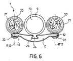
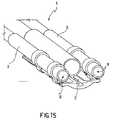
図示されている実施形態では、装置1は、それぞれが作動機構8と相互作用する、複数の、具体的には2つの管状部材3を含む。 In the embodiment shown, the
以降の記載では、1つの管状部材3および1つの作動機構すなわち1つの関節フレーム8に対して参照がなされるが、形状および機能の特徴ならびにこれらの相互作用は、1つの管状部材を備える実施形態および2つ以上の管状部材と、対応する2つ以上の作動機構とを備える実施形態の両方に当てはまることを理解されたい。 In the following description, reference will be made to one
関節フレーム8は、ベース構造2の固定ヒンジ部分12に回転可能に接続された第1の端部と、固定ヒンジ部分12よりも近位側のベース構造2のガイド部分13にスライド可能、具体的には長手方向に運動可能に接続された第2の端部を有する。このように、関節フレーム8の第2の端部がガイド13に沿って運動すると、関節フレーム8が変形して、従って、この関節フレームに接続された向き設定可能な端部5の向きが設定される。 The
一実施形態によると、関節フレーム8は、固定ヒンジ部分12に回転可能に接続された遠位端部15、および、第2の近位シャフト17の遠位端部18に回転可能に接続された近位端部16を有する第1の遠位シャフト14を含む。第2の近位シャフト17の近位端部19は、三角形関節フレームを形成するように、ベース構造2の前記の軸方向ガイド部分13に回転およびスライド可能に接続されている。 According to one embodiment, the
少なくとも固定ヒンジ部分12は、少なくとも遠位シャフト14が実質的に単一平面のみで運動できるように、回転軸R12を定めている。 At least the
2つの対向した管状部材の場合、両方の関節フレームの遠位シャフトの運動は、運動が同一平面に制限されるのが好ましいが、必ずしもそうでなくてもよい。 In the case of two opposed tubular members, the movement of the distal shaft of both articulated frames is preferably, but not necessarily, restricted to the same plane.
一実施形態によると、固定ヒンジ部分12は別として、2つの、遠位シャフト14と近位シャフト16との間の回転可能な接続、および、近位シャフトとガイド13との間の回転可能な接続は、関節フレーム8全体の移動および変形運動が、実質的に単一平面に制限されるように形成されている。このため、近位シャフトは、ガイド部分13に対する近位シャフト17の横断運動を防止するために、ガイド部分13を受容するのに適した長手方向スリット27を含むのが好ましい。 According to one embodiment, apart from the fixed
ヒンジ接続は、回転軸を定めるピンによってなされるのが好ましく、スライドガイド13は、直線的なスロットを含むのが好ましい。このスロットの方向は、スライド方向を定め、このスロット内で、近位シャフト17の近位端部19が、ピンによって固定されている。このピンは、ガイド13に対する近位シャフト17の近位端部19の回転軸R17を定めている。 The hinge connection is preferably made by a pin that defines the axis of rotation, and the
有利に、近位シャフト17の長さは、遠位シャフト14の長さよりも長い。このため、近位シャフト17の(ガイド13に沿った)作動運動と遠位シャフト14の角度向き設定回転との間の超比例関係(hyper-proportional relationship)が得られるようになっている。 Advantageously, the length of the
有利に、管状部材3の向き設定可能な遠位端部5は、実質的に遠位シャフト14と同じ方向または遠位シャフト14の長手方向に平行な方向に向き設定されるように、関節フレーム8の遠位シャフト14に固定されている。このため、装置1の嵩(bulk)および内視鏡または腹腔鏡全体の嵩を、患者の体に対する挿入および引戻し、ならびに体内の場所での手術の際に、可能な限り制限することができる。 Advantageously, the articulated frame is such that the orientable
関節フレーム8の最適な作動、および向き設定可能な端部5と遠位シャフト14との接続を可能にするために、向き設定可能な遠位部分5の管状部材3の、より近位の部分を、関節フレーム8の近位シャフト17に固定し、ベース構造2に対する管状部材3の運動が、ベース構造2のガイド部分13に沿った近位シャフト17のスライドに直接変換されるようにすることが有利に見越されている。 A more proximal portion of the
一実施形態によると、管状部材3を関節フレーム8に接続し、かつ関節フレームのシャフト14、17の長手方向軸の回りの管状部材3の回転を可能にする回転可能なコネクタ20が備えられている。このように、向き設定可能な遠位端部5、従って手術器具7の一方の、他方に対する、および内視鏡または腹腔鏡の軸方向の視野に対する、運動または位置の調節の更なる自由度が得られる。 According to one embodiment, a
有利なことに、(上記したさらなる回転を可能にする実施形態、および、この回転が防止される実施形態では、)コネクタ20は、前記の管状部材3を完全に取り囲んで把持している第1の管状部分21、および、フレーム8のシャフト14、17を完全に取り囲んで把持している第2の管状部分22を定めている2重スリーブ形状である。別法では、2つの管状部分は、オープンクリップ型プロフィールを有することができる。 Advantageously, the
関節フレーム8を、そのフレーム8の実質的に全ての領域で容易かつ有利に運動させるために、管状部材3は変形可能である。 In order to move the
一実施形態によると、コネクタ20の第1のコネクタにより、前記の管状部材3と前記の関節フレーム8との間の相対的な長手方向の運動が可能となり、コネクタ20の第2のコネクタにより、このような相対的な長手方向の運動が防止される。このため、関節フレームの運動が、関節フレームの運動と管状部材の運動との間の不適合による制限から実質的に自由になる。挿入チューブに対する管状部材の遠位端部の不所望の長手方向の運動を回避するために、第1のコネクタ(固定接続)が、近位シャフト17と管状部材3を接続し、第2のコネクタ(スライド接続)が、遠位シャフト14と管状部材3を接続するのが好ましい。 According to one embodiment, the first connector of the
管状部材3の向き設定可能な遠位部分5の長手方向軸R5を中心に手術器具7が回転できるように、座部6がこの手術器具を支持するように作られた場合、挿入チューブ10の軸方向の視野に対する手術器具7の運動のさらなる自由度が得られる。 When the
一実施形態によると、ベース構造2は、挿入チューブ10の遠位端部部分9に形成されたカウンターガイドプロフィール24との様々な位置での接続を可能にするガイドプロフィール23を介して、挿入チューブ10に接続することができる。好ましくは、ガイドプロフィール23およびカウンターガイドプロフィール24は、挿入チューブ10の遠位端部部分9の長手方向軸R10に実質的に平行な調節方向を定める。特に有利なことに、ガイドプロフィール23およびカウンターガイドプロフィール24は、例えば、ハトの尾形の切り込みを有する実質的に適合する断面を有していて、不用意に外れるのを効果的に防止している。 According to one embodiment, the
有利に、ガイド23とカウンターガイド24との間の結合は、例えば、プレス嵌め型の摩擦結合である。スナップ固定によってガイド23とカウンターガイド24の相互位置を調節できるように、ガイド23および/またはカウンターガイド24に沿って弾性的にたわむ刻み付きトラックまたは歯付きトラックを見越すこともできる。 Advantageously, the coupling between the
好適な実施形態によると、カウンターガイドプロフィール24は、例えば、挿入チューブ10の遠位端部とのプレス嵌めによって接続できる、好ましくは管状の接続部28の外面に形成されている。もちろん、好適な接続は既に記載したが、当業者であれば、本発明から逸脱することなく、挿入チューブ10の遠位端部部分9に沿って、様々な位置で挿入チューブ10にベース構造2を接続できる(すなわち、接続位置を調節することができる)類似の実施形態を選択できるであろう。 According to a preferred embodiment, the
好適な実施形態によると、ベース構造2は、例えば、図1および図5に示されているように、単一の部品になるよう形成された本体である。 According to a preferred embodiment, the
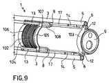
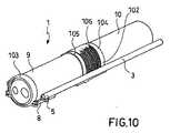
代替の実施形態(図7〜図10)によると、ベース構造102は、遠位部分103、およびこの遠位部分103から離隔した近位部分104を含む。 According to alternative embodiments (FIGS. 7-10), the
遠位部分103は、固定ヒンジ部分12を形成し、挿入チューブ10の遠位端部部分9に接続されている。ベース構造の近位部分104は、ガイド部分13を形成し、同様に挿入チューブ10の遠位端部部分9に接続されているが、遠位部分103から離れた近位位置にある。 The
有利に、スライドリング105が、近位シャフト17の近位端部19に接続され、ガイド部分13によってスライド式に案内される。好ましくは引張りコイルバネまたは類似の弾性付勢部材であるバネ106が、関節フレーム8をその静止配置に弾性的に付勢するために、近位部分104とスライドリング105との間で作用する。さらに有利に、バネ106自体は、ガイド部分13自体の溝107または別個の平行な溝108内に受容されて案内される。 Advantageously, the
同様のまたは類似の弾性付勢部材を、作動機構8を永久的に静止配置に弾性的に付勢するために、ここに記載および例示した他の実施形態に有利に設けることもできる。一例として、上記の付勢部材は、ベース構造2と関節フレーム8との間で作用する弾性バネから、または関節フレーム8に近接した管状部材に直接一体化されたバネ効果を有する弾性材料から作ることができる。 Similar or similar resilient biasing members may be advantageously provided in other embodiments described and illustrated herein for resiliently biasing the
管状部材3は、その近位端部4から向き設定可能な遠位端部5への手術器具7の移送を可能にするチャネル34を内部に定めている。
管状部材3は、その近位端部4と作動機構との間に配列された少なくとも1つの伝達部分25を含む。一実施形態によると、伝達部分25は、実質的に硬質の管状ロッド25’から形成されている。管状ロッド25’の剛性により、管状部材3を挿入チューブ10に固定するために特別なガイドを見越す必要なく、従って、従来の内視鏡または腹腔鏡の一般的な構造に支障を与えずに、作動機構8を作動させることが可能である。代替の実施形態によると、伝達部分25は、可撓性管状部分25’’を含み、この部分は、挿入チューブ10の長手方向の運動のみを実質的に可能にするように、内視鏡の挿入チューブ10に対する、実質的に可撓性の管状部分25’’の運動を制約するガイド26内で案内される。可撓性挿入チューブの場合、挿入チューブ10に平行に配列されて接続された、例えば変形可能なホースであるガイド25により、可撓性部分25’’が挿入チューブ自体と共に、ヒトまたは動物の体内の天然の導管の不規則な形状に従うことができる。
図11および図12に例示されている実施形態は、ベース構造2に一点で回転可能に接続された管状部材3自体の制御された変形によって、関節フレームの機能を果たすことができる。このような回転可能な接続は、接合部112の回転軸を定めるピンを用いずに、例えば、弾性変形可能な接合部112によって実現することができる。 The embodiment illustrated in FIGS. 11 and 12 can serve as an articulated frame by controlled deformation of the
有利なことに、既存の内視鏡および腹腔鏡のための付属品としてここに記載した装置を製造および使用することができ、また、取外し可能な構成要素または取外しできない構成要素として体組織の処理のための本装置を含む内視鏡または腹腔鏡を製造および使用することができる。 Advantageously, the device described herein can be manufactured and used as an accessory for existing endoscopes and laparoscopes, and treatment of body tissue as a removable or non-removable component Endoscopes or laparoscopes comprising this device for can be manufactured and used.
これ以降は、本発明による体組織の処理のための装置の動作について記載する。 In the following, the operation of the device for the treatment of body tissue according to the invention will be described.
ベース本体2のガイド23と挿入チューブのカウンターガイド24との結合、所望の組立位置における相互の位置付け、およびネジ手段、スナップ手段、摩擦手段、または他の固定手段などの固定手段による接続部の固定によって、装置1が、腹腔鏡または内視鏡の挿入チューブ10に取り付けられる。 Coupling of the
管状部材3の近位端部4を近位方向に引くよう保持することにより、関節フレーム8の近位シャフト17の近位端部19は、ベース構造2のガイド13の近位制限位置に位置付けられ、関節フレームと管状部材3の向き設定可能な遠位端部5の双方を挿入チューブに整合させる。この静止配置では、装置1の嵩が最小であり、患者の体内の所望の場所まで腹腔鏡または内視鏡を挿入することができる。 By holding the proximal end 4 of the
挿入チューブ10の位置付けの後、装置1は静止配置に保たれ、手術器具7は、この手術器具7が適切な座部6内に受容される管状部材の遠位端部5まで、管状部材のチャネル34内を通される。 After positioning of the
挿入チューブの長手方向軸R10に対する手術器具の向き設定は、挿入チューブ10に対する管状部材3の作動部分11の遠位方向の運動(装置1の作動配置)によって容易に行うことができる。チャネル34により、介入の際に手術器具を交換することが可能である。交換するためには、管状部材3の作動部分11を近位方向に引いて、装置1を静止配置にすればよく、よって管状部材3の遠位部分5は実質的に直線状になり、これまで使用した手術器具を引き抜いて別の手術器具と交換することができる。 The orientation of the surgical instrument relative to the longitudinal axis R <b> 10 of the insertion tube can be easily performed by the movement in the distal direction of the operating
挿入の場合と同様に、装置1が静止配置にある状態で、内視鏡または腹腔鏡の患者の体内からの引き抜きが行われる。 As with the insertion, the endoscope or laparoscope is withdrawn from the patient's body with the
本発明による装置は、様々な利点を有する。 The device according to the invention has various advantages.
本発明による装置の特徴により、挿入チューブの内部構造に支障を与えず、かつ手術器具のために別のアクセス点(切開部)を必要とすることなく、1つの内視鏡または腹腔鏡を用いて手術器具の挿入チューブに対する幅広い角度を得ることが可能である。 Due to the features of the device according to the present invention, one endoscope or laparoscope is used without disturbing the internal structure of the insertion tube and without requiring a separate access point (incision) for the surgical instrument. Thus, it is possible to obtain a wide angle with respect to the insertion tube of the surgical instrument.
装置1により、手術器具を、管状部材の近位端部からその向き設定可能な遠位端部まで移送することができ、また、挿入チューブを抜き取って再挿入する必要なく、介入の際に手術器具を交換することができる。 The
硬質の伝達ロッドを備えた実施形態では、管状部材を挿入チューブに固定するために特別なガイドを見越す必要がなく、従って従来の内視鏡または腹腔鏡の典型的な構造に支障を与えずに、作動機構を作動させることができる。 In embodiments with a rigid transmission rod, there is no need to forego special guides to secure the tubular member to the insertion tube, and thus without disturbing the typical structure of a conventional endoscope or laparoscope The actuating mechanism can be actuated.
可撓性伝達部分を備えた実施形態では、例えば内視鏡の可撓性挿入チューブの変形形状に従うことが可能である。 In embodiments with a flexible transmission portion, it is possible to follow the deformed shape of the flexible insertion tube of an endoscope, for example.
関節フレームの特殊な形状と、関節フレームが管状部材3と別個であるという事実から、向き設定機能と、手術器具の移送機能、支持機能、および作動機能との有利な分離をなすことができる。 Due to the special shape of the articulated frame and the fact that the articulated frame is separate from the
関節フレームの特殊な配置、従って作動機構の運動の制約によって、手術器具の特に安定した制御可能な運動と、同時の軸方向の運動とならない手術器具の向き設定の調節が実現可能となっている。 Due to the special arrangement of the joint frame and thus the movement restrictions of the actuating mechanism, it is possible to achieve a particularly stable and controllable movement of the surgical instrument and an adjustment of the orientation setting of the surgical instrument which does not result in simultaneous axial movement. .
〔実施の態様〕
(1)体組織を処理するための装置1において、
ベース構造2、102と、
近位端部4、および、手術器具7を支持するための座部6を定めている向き設定可能な遠位端部5を有する少なくとも1つの管状部材3であって、前記管状部材3は、前記ベース構造2に接続されている、管状部材3と、
前記管状部材3の前記遠位端部5の向きを設定してこの遠位端部を所定の動作配置にするのに適した作動機構8であって、前記作動機構8は、前記ベース構造2に接続されている、作動機構8と、
前記作動機構8および前記管状部材3が内視鏡または腹腔鏡の挿入チューブ10の外側に配列されるように、前記挿入チューブ10の遠位端部部分9に前記ベース構造2を接続するための手段23、24と、
を含み、
前記管状部材3は、前記ベース構造2に対する前記管状部材3の作動部分11の運動によって、前記向き設定可能な端部5の前記向き設定がなされるように、前記作動機構8と相互作用する、装置1。
(2)実施態様(1)に記載の装置1において、
前記管状部材3は、前記管状部材3の前記近位端部4から前記向き設定可能な遠位端部5への前記手術器具7の移送を可能にするチャネル34を内部に定めている、装置1。
(3)実施態様(1)または(2)に記載の装置1において、
前記管状部材3は、前記作動機構8と前記管状部材3の前記近位端部4との間に配列された、少なくとも1つの伝達部分25を含み、
前記伝達部分25は、実質的に硬質の管状ロッド25’を含む、装置1。
(4)実施態様(1)から(3)のいずれかに記載の装置1において、
前記管状部材3は、
前記作動機構8と前記管状部材3の前記近位端部4との間に配列された少なくとも1つのガイドされた伝達部分25と、
実質的に前記挿入チューブ10の長手方向でのみ、前記ガイド伝達された部分25の運動が可能になるように、前記挿入チューブ10に対する前記伝達部分25の運動を制約するのに適したガイド26と、
を含む、装置1。
(5)実施態様(4)に記載の装置1において、
前記ガイドされた伝達部分25は、可撓性挿入チューブの変形形状に従うことができるように可撓性部分25’’を含む、装置1。Embodiment
(1) In the
At least one
An
For connecting the
Including
The
(2) In the
The
(3) In the
The
(4) In the
The
At least one guided
A
A
(5) In the
(6)実施態様(1)から(5)のいずれかに記載の装置1において、
前記作動機構は、関節フレーム8を含む、装置1。
(7)実施態様(6)に記載の装置1において、
前記関節フレーム8は、前記ベース構造2の固定ヒンジ部分12に回転可能に接続された第1の端部15、および、前記固定ヒンジ部分12に対して、より近位側の前記ベース構造2のガイド部分13にスライド可能に接続された第2の端部19を含み、よって、前記関節フレーム8の前記第2の端部19の、前記ガイド部分13に沿った運動により、前記関節フレーム8が変形するようになっており、
前記管状部材3の前記向き設定可能な遠位端部5は、前記関節フレーム8の前記変形によって前記向き設定可能な端部5の前記向き設定がなされるように、前記関節フレーム8に接続されている、装置1。
(8)実施態様(7)に記載の装置1において、
前記関節フレーム8は、
前記固定ヒンジ部分13に回転可能に接続された遠位端部15、および、近位端部16を有する遠位シャフト14と、
三角形状に関節連結されたフレームを形成するように、前記ガイド部分13にスライド可能に接続された近位端部19、および、前記遠位シャフト14の前記近位端部16に回転可能に接続された遠位端部18を有する、近位シャフト17と、
を含む、装置1。
(9)実施態様(8)に記載の装置1において、
少なくとも前記固定ヒンジ部分12は、前記遠位シャフト14が実質的に単一平面のみで運動できるように回転軸R12を定めている、装置1。
(10)実施態様(8)または(9)に記載の装置1において、
前記近位シャフト17は、前記遠位シャフト14の長さよりも長い、装置1。(6) In the
The operating mechanism comprises an
(7) In the
The
The
(8) In the
The
A
A
A
(9) In the
At least the
(10) In the
The
(11)実施態様(8)から(10)のいずれかに記載の装置1において、
前記管状部材3の前記向き設定可能な遠位部分5は、前記遠位シャフト14が向き設定されている方向と実質的に同じ方向に向き設定されるように、前記関節フレーム8の前記遠位シャフト14に固定されている、装置1。
(12)実施態様(8)から(11)のいずれかに記載の装置1において、
前記向き設定可能な遠位端部5の、より近位側の前記管状部材3の部分は、前記ベース構造2に対する前記管状部材3の前記運動によって、前記近位シャフト17が前記ベース構造2の前記ガイド部分13内をスライドするように、前記関節フレーム8の前記近位シャフト17に固定されている、装置1。
(13)実施態様(6)から(12)のいずれかに記載の装置1において、
前記関節フレーム8の前記シャフト14、17の長手方向軸の回りでの前記管状部材3の回転によって、前記管状部材3の位置を調節できるように、前記管状部材3を前記関節フレーム8に接続する回転可能な接続手段20、21、22、
を含む、装置1。
(14)実施態様(8)から(13)のいずれかに記載の装置1において、
前記管状部材3を完全に取り囲んで把持する第1の管状部分21、および、前記関節フレーム8の前記シャフト14、17を完全に取り囲んで把持する第2の管状部分22を形成している、1つまたは複数の2重スリーブコネクタ20、
を含む、装置1。
(15)実施態様(14)に記載の装置1において、
前記コネクタ20の第1のコネクタにより、前記管状部材3と前記関節フレーム8との間の相対的な長手方向の運動が可能となり、前記コネクタ20の第2のコネクタにより、このような相対的な長手方向の運動が防止される、装置1。(11) In the
The orientable
(12) In the
The portion of the
(13) In the
The
A
(14) In the
A first
A
(15) In the
The first connector of the
(16)実施態様(15)に記載の装置1において、
前記第1のコネクタは、前記近位シャフト17を前記管状部材3に接続し、前記第2のコネクタは、前記遠位シャフト14を前記管状部材3に接続している、装置1。
(17)実施態様(6)から(16)のいずれかに記載の装置1において、
前記関節フレーム8の領域において、前記管状部材3は変形可能である、装置1。
(18)実施態様(1)から(17)のいずれかに記載の装置1において、
手術器具7を支持するための前記座部6により、前記管状部材3の前記向き設定可能な遠位部分5の長手方向軸R5を中心とする前記手術器具7の回転が可能となっている、装置1。
(19)実施態様(1)から(18)のいずれかに記載の装置1において、
前記挿入チューブ10の前記遠位端部部分9に沿った様々な位置で、前記ベース構造2が前記挿入チューブ10に接続されるのを可能にする調節手段23、24、
を含む、装置1。
(20)実施態様(1)から(19)のいずれかに記載の装置1において、
前記ベース構造2は、前記挿入チューブ10の前記遠位端部部分9に接続されたカウンターガイドプロフィール24に様々な位置で結合できるような形状を有するガイドプロフィール23を定めており、
前記ガイドプロフィール23および前記カウンターガイドプロフィール24は、前記挿入チューブ10の前記遠位端部部分9の長手方向軸R10に実質的に平行な調節方向を定めている、装置1。(16) In the
The
(17) In the
In the region of the
(18) In the
The
(19) In the
Adjusting means 23, 24, which allow the
A
(20) In the
The
The
(21)実施態様(20)に記載の装置1において、
前記カウンターガイドプロフィール24は、前記挿入チューブ10の遠位端部に接続できる接続部分28の外面に形成されている、装置1。
(22)実施態様(21)に記載の装置1において、
前記接続部分28は、プレス嵌めによって前記挿入チューブ10の前記遠位端部に接続できる、装置1。
(23)実施態様(1)から(22)のいずれかに記載の装置1において、
前記作動機構8を前記静止配置に弾性的に付勢するのに適した付勢手段、
を含む、装置1。
(24)実施態様(23)に記載の装置1において、
前記付勢手段は、前記ベース構造2と前記関節フレーム8との間で作用する弾性バネを含む、装置1。
(25)実施態様(24)に記載の装置1において、
前記弾性バネは、予め引張り荷重がかけられている(preloaded in traction)、装置1。(21) In the
The
(22) In the
The
(23) In the
Biasing means suitable for resiliently biasing the
A
(24) In the
The
(25) In the
The elastic spring is a
(26)実施態様(23)に記載の装置1において、
前記付勢手段は、前記関節フレーム8の近傍で前記管状部材に組み込まれている、装置1。
(27)実施態様(1)から(26)のいずれかに記載の装置1において、
前記ベース構造2は、単一の部品になるよう形成された本体である、装置1。
(28)実施態様(1)から(26)のいずれかに記載の装置1において、
前記ベース構造102は、
前記挿入チューブ10の前記遠位端部部分9に固定することができ、かつ、前記固定ヒンジ部分12を含む、遠位部分103と、
前記遠位部分103から離隔されている近位部分104であって、前記遠位部分103に対して離間した近位側の位置で、前記挿入チューブ10の前記遠位端部部分9に固定することができ、かつ、前記ガイド部分13を含む、近位部分104と、
を含む、装置1。
(29)実施態様(28)に記載の装置1において、
前記近位シャフト17の前記近位端部19に接続され、かつ、前記ガイド部分13によってスライド式に案内されるスライドリング、
を含み、
前記付勢手段は、前記近位部分104と前記スライドリングとの間で作用する、装置1。
(30)実施態様(1)から(29)のいずれかに記載の装置1において、
前記作動機構は、前記管状部材3とは別個であるが前記管状部材3に接続された関節フレーム8を含む、装置1。(26) In the
The
(27) In the
The
(28) In the
The
A
A
A
(29) In the
A slide ring connected to the
Including
The
(30) In the
The
(31)実施態様(1)から(30)のいずれかに記載の装置1において、
2つ以上の前記管状部材3と、
2つ以上の前記作動機構8と、
を含み、
各前記管状部材3はそれぞれ、実施態様(1)から(30)の1つまたは複数で請求されるように、前記作動機構8のうちの1つと相互作用する、装置1。
(32)内視鏡において、
実施態様(1)から(31)のいずれかに記載の装置1を含む、内視鏡。
(33)腹腔鏡において、
実施態様(1)から(31)のいずれかに記載の装置1を含む、腹腔鏡。(31) In the
Two or more
Two or
Including
(32) In an endoscope,
An endoscope comprising the
(33) In a laparoscope,
Laparoscope comprising the
Claims (33)
Translated fromJapaneseベース構造(2、102)と、
近位端部(4)、および、手術器具(7)を支持するための座部(6)を定めている向き設定可能な遠位端部(5)を有する少なくとも1つの管状部材(3)であって、前記管状部材(3)は、前記ベース構造(2)に接続されている、管状部材(3)と、
前記管状部材(3)の前記遠位端部(5)の向きを設定してこの遠位端部を所定の動作配置にするのに適した作動機構(8)であって、前記作動機構(8)は、前記ベース構造(2)に接続されている、作動機構(8)と、
前記作動機構(8)および前記管状部材(3)が内視鏡または腹腔鏡の挿入チューブ(10)の外側に配列されるように、前記挿入チューブ(10)の遠位端部部分(9)に前記ベース構造(2)を接続するための手段(23、24)と、
を含み、
前記管状部材(3)は、前記ベース構造(2)に対する前記管状部材(3)の作動部分(11)の運動によって、前記向き設定可能な端部(5)の前記向き設定がなされるように、前記作動機構(8)と相互作用する、装置。In a device (1) for treating body tissue,
A base structure (2, 102);
At least one tubular member (3) having a proximal end (4) and an orientable distal end (5) defining a seat (6) for supporting a surgical instrument (7) The tubular member (3) is connected to the base structure (2), the tubular member (3);
An actuating mechanism (8) suitable for setting the orientation of the distal end (5) of the tubular member (3) to place the distal end in a predetermined operating arrangement, the actuating mechanism (8) 8) an actuating mechanism (8) connected to the base structure (2);
The distal end portion (9) of the insertion tube (10) so that the actuation mechanism (8) and the tubular member (3) are arranged outside the insertion tube (10) of an endoscope or laparoscope Means (23, 24) for connecting the base structure (2) to
Including
In the tubular member (3), the orientation of the end portion (5) whose orientation can be set is set by the movement of the operating portion (11) of the tubular member (3) with respect to the base structure (2). The device interacting with the actuating mechanism (8).
前記管状部材(3)は、前記管状部材(3)の前記近位端部(4)から前記向き設定可能な遠位端部(5)への前記手術器具(7)の移送を可能にするチャネル(34)を内部に定めている、装置。Device (1) according to claim 1,
The tubular member (3) allows transfer of the surgical instrument (7) from the proximal end (4) of the tubular member (3) to the orientable distal end (5). A device having a channel (34) defined therein.
前記管状部材(3)は、前記作動機構(8)と前記管状部材(3)の前記近位端部(4)との間に配列された、少なくとも1つの伝達部分(25)を含み、
前記伝達部分(25)は、実質的に硬質の管状ロッド(25’)を含む、装置。Device (1) according to claim 1 or 2,
The tubular member (3) includes at least one transmission portion (25) arranged between the actuating mechanism (8) and the proximal end (4) of the tubular member (3);
The device, wherein the transmission portion (25) comprises a substantially rigid tubular rod (25 ').
前記管状部材(3)は、
前記作動機構(8)と前記管状部材(3)の前記近位端部(4)との間に配列された少なくとも1つのガイドされた伝達部分(25)と、
実質的に前記挿入チューブ(10)の長手方向でのみ、前記ガイドされた伝達部分(25)の運動が可能になるように、前記挿入チューブ(10)に対する前記伝達部分(25)の運動を制約するのに適したガイド(26)と、
を含む、装置。Device (1) according to any of claims 1 to 3,
The tubular member (3)
At least one guided transmission portion (25) arranged between the actuation mechanism (8) and the proximal end (4) of the tubular member (3);
Restricting movement of the transmission part (25) relative to the insertion tube (10) so that movement of the guided transmission part (25) is possible substantially only in the longitudinal direction of the insertion tube (10). A guide (26) suitable for
Including the device.
前記ガイドされた伝達部分(25)は、可撓性挿入チューブの変形形状に従うことができるように可撓性部分(25’’)を含む、装置。Device (1) according to claim 4,
The apparatus wherein the guided transmission portion (25) includes a flexible portion (25 '') so that it can follow the deformed shape of the flexible insertion tube.
前記作動機構は、関節フレーム(8)を含む、装置。Device (1) according to any of the preceding claims,
The device, wherein the actuation mechanism comprises a joint frame (8).
前記関節フレーム(8)は、前記ベース構造(2)の固定ヒンジ部分(12)に回転可能に接続された第1の端部(15)、および、前記固定ヒンジ部分(12)に対して、より近位側の前記ベース構造(2)のガイド部分(13)にスライド可能に接続された第2の端部(19)を含み、よって、前記関節フレーム(8)の前記第2の端部(19)の、前記ガイド部分(13)に沿った運動により、前記関節フレーム(8)が変形するようになっており、
前記管状部材(3)の前記向き設定可能な遠位端部(5)は、前記関節フレーム(8)の前記変形によって前記向き設定可能な端部(5)の前記向き設定がなされるように、前記関節フレーム(8)に接続されている、装置。Device (1) according to claim 6,
The joint frame (8) is relative to a first end (15) rotatably connected to a fixed hinge portion (12) of the base structure (2), and to the fixed hinge portion (12), Including a second end (19) slidably connected to the guide portion (13) of the base structure (2) on the more proximal side, and thus the second end of the articulated frame (8) The joint frame (8) is deformed by movement along the guide portion (13) of (19),
The distal end portion (5) capable of setting the orientation of the tubular member (3) is configured such that the orientation of the end portion (5) capable of setting the orientation is set by the deformation of the joint frame (8). The device connected to the joint frame (8).
前記関節フレーム(8)は、
前記固定ヒンジ部分(13)に回転可能に接続された遠位端部(15)、および、近位端部(16)を有する、遠位シャフト(14)と、
三角形状に関節連結されたフレームを形成するように、前記ガイド部分(13)にスライド可能に接続された近位端部(19)、および、前記遠位シャフト(14)の前記近位端部(16)に回転可能に接続された遠位端部(18)を有する、近位シャフト(17)と、
を含む、装置。Device (1) according to claim 7,
The joint frame (8)
A distal shaft (14) having a distal end (15) rotatably connected to the fixed hinge portion (13) and a proximal end (16);
A proximal end (19) slidably connected to the guide portion (13) to form a triangular articulated frame; and the proximal end of the distal shaft (14) A proximal shaft (17) having a distal end (18) rotatably connected to (16);
Including the device.
少なくとも前記固定ヒンジ部分(12)は、前記遠位シャフト(14)が実質的に単一平面のみで運動できるように回転軸(R12)を定めている、装置。Device (1) according to claim 8,
The apparatus, wherein at least the fixed hinge portion (12) defines an axis of rotation (R12) such that the distal shaft (14) can move substantially in only a single plane.
前記近位シャフト(17)は、前記遠位シャフト(14)の長さよりも長い、装置。Device (1) according to claim 8 or 9,
The device, wherein the proximal shaft (17) is longer than the length of the distal shaft (14).
前記管状部材(3)の前記向き設定可能な遠位部分(5)は、前記遠位シャフト(14)が向き設定されている方向と実質的に同じ方向に向き設定されるように、前記関節フレーム(8)の前記遠位シャフト(14)に固定されている、装置。Device (1) according to any of claims 8 to 10,
The articulating distal portion (5) of the tubular member (3) is oriented in substantially the same direction as the distal shaft (14) is oriented. Device secured to the distal shaft (14) of a frame (8).
前記向き設定可能な遠位端部(5)の、より近位側の前記管状部材(3)の部分は、前記ベース構造(2)に対する前記管状部材(3)の前記運動によって、前記近位シャフト(17)が前記ベース構造(2)の前記ガイド部分(13)内をスライドするように、前記関節フレーム(8)の前記近位シャフト(17)に固定されている、装置。Device (1) according to any of claims 8 to 11,
The portion of the tubular member (3) that is more proximal to the orientable distal end (5) is moved by the movement of the tubular member (3) relative to the base structure (2). A device wherein the shaft (17) is fixed to the proximal shaft (17) of the articulated frame (8) so that it slides within the guide portion (13) of the base structure (2).
前記関節フレーム(8)の前記シャフト(14、17)の長手方向軸の回りでの前記管状部材(3)の回転によって、前記管状部材(3)の位置を調節できるように、前記管状部材(3)を前記関節フレーム(8)に接続する回転可能な接続手段(20、21、22)、
を含む、装置。Device (1) according to any of claims 6 to 12,
The tubular member (3) can be adjusted by rotation of the tubular member (3) about the longitudinal axis of the shaft (14, 17) of the joint frame (8). 3) rotatable connecting means (20, 21, 22) for connecting the joint frame (8)
Including the device.
前記管状部材(3)を完全に取り囲んで把持する第1の管状部分(21)、および、前記関節フレーム(8)の前記シャフト(14、17)を完全に取り囲んで把持する第2の管状部分(22)を形成している、1つまたは複数の2重スリーブコネクタ(20)、
を含む、装置。Device (1) according to any of claims 8 to 13,
A first tubular part (21) that completely surrounds and grips the tubular member (3), and a second tubular part that completely surrounds and grips the shaft (14, 17) of the joint frame (8). One or more double sleeve connectors (20) forming (22),
Including the device.
前記コネクタ(20)の第1のコネクタにより、前記管状部材(3)と前記関節フレーム(8)との間の相対的な長手方向の運動が可能となり、前記コネクタ(20)の第2のコネクタにより、このような相対的な長手方向の運動が防止される、装置。Device (1) according to claim 14,
The first connector of the connector (20) allows relative longitudinal movement between the tubular member (3) and the joint frame (8), and the second connector of the connector (20). Thereby preventing such relative longitudinal movement.
前記第1のコネクタは、前記近位シャフト(17)を前記管状部材(3)に接続し、前記第2のコネクタは、前記遠位シャフト(14)を前記管状部材(3)に接続している、装置。Device (1) according to claim 15,
The first connector connects the proximal shaft (17) to the tubular member (3), and the second connector connects the distal shaft (14) to the tubular member (3). The equipment.
前記関節フレーム(8)の領域において、前記管状部材(3)は変形可能である、装置。Device (1) according to any of claims 6 to 16,
In the region of the articulation frame (8), the tubular member (3) is deformable.
手術器具(7)を支持するための前記座部(6)により、前記管状部材(3)の前記向き設定可能な遠位部分(5)の長手方向軸(R5)を中心とする前記手術器具(7)の回転が可能となっている、装置。Device (1) according to any of the preceding claims,
The surgical instrument about the longitudinal axis (R5) of the distally configurable distal portion (5) of the tubular member (3) by means of the seat (6) for supporting the surgical instrument (7) An apparatus capable of rotating in (7).
前記挿入チューブ(10)の前記遠位端部部分(9)に沿った様々な位置で、前記ベース構造(2)が前記挿入チューブ(10)に接続されるのを可能にする調節手段(23、24)、
を含む、装置。Device (1) according to any of the preceding claims,
Adjustment means (23) that allow the base structure (2) to be connected to the insertion tube (10) at various locations along the distal end portion (9) of the insertion tube (10). 24),
Including the device.
前記ベース構造(2)は、前記挿入チューブ(10)の前記遠位端部部分(9)に接続されたカウンターガイドプロフィール(24)に様々な位置で結合できるような形状を有するガイドプロフィール(23)を定めており、
前記ガイドプロフィール(23)および前記カウンターガイドプロフィール(24)は、前記挿入チューブ(10)の前記遠位端部部分(9)の長手方向軸(R10)に実質的に平行な調節方向を定めている、装置。Device (1) according to any of the preceding claims,
The base structure (2) has a guide profile (23) shaped to be able to couple at various positions to a counter guide profile (24) connected to the distal end portion (9) of the insertion tube (10). )
The guide profile (23) and the counter guide profile (24) define an adjustment direction substantially parallel to the longitudinal axis (R10) of the distal end portion (9) of the insertion tube (10). The equipment.
前記カウンターガイドプロフィール(24)は、前記挿入チューブ(10)の遠位端部に接続できる接続部分(28)の外面に形成されている、装置。Device (1) according to claim 20,
The device, wherein the counterguide profile (24) is formed on the outer surface of a connecting portion (28) that can be connected to the distal end of the insertion tube (10).
前記接続部分(28)は、プレス嵌めによって前記挿入チューブ(10)の前記遠位端部に接続できる、装置。Device (1) according to claim 21,
The device, wherein the connection portion (28) can be connected to the distal end of the insertion tube (10) by a press fit.
前記作動機構(8)を前記静止配置に弾性的に付勢するのに適した付勢手段、
を含む、装置。Device (1) according to any of claims 1 to 22,
Biasing means suitable for resiliently biasing the actuating mechanism (8) to the stationary arrangement;
Including the device.
前記付勢手段は、前記ベース構造(2)と前記関節フレーム(8)との間で作用する弾性バネを含む、装置。Device (1) according to claim 23,
The device, wherein the biasing means comprises an elastic spring acting between the base structure (2) and the joint frame (8).
前記弾性バネは、予め引張り荷重がかけられている、装置。Device (1) according to claim 24,
The elastic spring is a device in which a tensile load is applied in advance.
前記付勢手段は、前記関節フレーム(8)の近傍で前記管状部材に組み込まれている、装置。Device (1) according to claim 23,
The device, wherein the biasing means is incorporated in the tubular member in the vicinity of the joint frame (8).
前記ベース構造(2)は、単一の部品になるよう形成された本体である、装置。Device (1) according to any of the preceding claims,
The device wherein the base structure (2) is a body formed to be a single piece.
前記ベース構造(102)は、
前記挿入チューブ(10)の前記遠位端部部分(9)に固定することができ、かつ、前記固定ヒンジ部分(12)を含む、遠位部分(103)と、
前記遠位部分(103)から離隔されている近位部分(104)であって、前記遠位部分(103)に対して離間した近位側の位置で、前記挿入チューブ(10)の前記遠位端部部分(9)に固定することができ、かつ、前記ガイド部分(13)を含む、近位部分(104)と、
を含む、装置。Device (1) according to any of the preceding claims,
The base structure (102)
A distal portion (103) that can be secured to the distal end portion (9) of the insertion tube (10) and includes the stationary hinge portion (12);
A proximal portion (104) spaced from the distal portion (103), the proximal portion of the insertion tube (10) at a proximal position spaced from the distal portion (103); A proximal portion (104) that can be secured to the distal end portion (9) and includes the guide portion (13);
Including the device.
前記近位シャフト(17)の前記近位端部(19)に接続され、かつ、前記ガイド部分(13)によってスライド式に案内される、スライドリング、
を含み、
前記付勢手段は、前記近位部分(104)と前記スライドリングとの間で作用する、装置。Device (1) according to claim 28,
A slide ring connected to the proximal end (19) of the proximal shaft (17) and slidably guided by the guide portion (13);
Including
The apparatus, wherein the biasing means acts between the proximal portion (104) and the slide ring.
前記作動機構は、前記管状部材(3)とは別個であるが前記管状部材(3)に接続された関節フレーム(8)を含む、装置。Device (1) according to any of the preceding claims,
The actuating mechanism comprises an articulated frame (8) separate from the tubular member (3) but connected to the tubular member (3).
2つ以上の前記管状部材(3)と、
2つ以上の前記作動機構(8)と、
を含み、
各前記管状部材(3)はそれぞれ、請求項1から30の1つまたは複数で請求されるように、前記作動機構(8)のうちの1つと相互作用する、装置。Device (1) according to any of claims 1 to 30,
Two or more tubular members (3);
Two or more actuating mechanisms (8);
Including
Apparatus wherein each said tubular member (3) interacts with one of said actuating mechanisms (8), as claimed in one or more of claims 1-30.
請求項1から31のいずれかに記載の装置(1)を含む、内視鏡。In an endoscope,
Endoscope comprising the device (1) according to any of claims 1 to 31.
請求項1から31のいずれかに記載の装置(1)を含む、腹腔鏡。In a laparoscope,
Laparoscope comprising the device (1) according to any of claims 1 to 31.
Applications Claiming Priority (2)
| Application Number | Priority Date | Filing Date | Title |
|---|---|---|---|
| IT000443AITMI20060443A1 (en) | 2006-03-13 | 2006-03-13 | DEVICE FOR THE MANIPULATION OF BODY TEXTILE |
| PCT/EP2007/001168WO2007104397A1 (en) | 2006-03-13 | 2007-02-12 | Device for the manipulation of body tissue |
Publications (1)
| Publication Number | Publication Date |
|---|---|
| JP2009529390Atrue JP2009529390A (en) | 2009-08-20 |
Family
ID=37965060
Family Applications (1)
| Application Number | Title | Priority Date | Filing Date |
|---|---|---|---|
| JP2008558663APendingJP2009529390A (en) | 2006-03-13 | 2007-02-12 | Device for processing body tissue |
Country Status (6)
| Country | Link |
|---|---|
| US (1) | US20100036198A1 (en) |
| EP (1) | EP1993430A1 (en) |
| JP (1) | JP2009529390A (en) |
| CN (1) | CN101400293B (en) |
| IT (1) | ITMI20060443A1 (en) |
| WO (1) | WO2007104397A1 (en) |
Cited By (3)
| Publication number | Priority date | Publication date | Assignee | Title |
|---|---|---|---|---|
| JP2016538010A (en)* | 2013-10-11 | 2016-12-08 | エンド ツールズ セラピューティクス エス.エー. | Device for supporting endoscopic tools |
| JP2019508145A (en)* | 2016-03-01 | 2019-03-28 | クック・メディカル・テクノロジーズ・リミテッド・ライアビリティ・カンパニーCook Medical Technologies Llc | Endoscope accessory channel to deflect |
| JP2022126757A (en)* | 2016-03-01 | 2022-08-30 | クック・メディカル・テクノロジーズ・リミテッド・ライアビリティ・カンパニー | scope system |
Families Citing this family (107)
| Publication number | Priority date | Publication date | Assignee | Title |
|---|---|---|---|---|
| US8944070B2 (en) | 1999-04-07 | 2015-02-03 | Intuitive Surgical Operations, Inc. | Non-force reflecting method for providing tool force information to a user of a telesurgical system |
| US9943372B2 (en) | 2005-04-18 | 2018-04-17 | M.S.T. Medical Surgery Technologies Ltd. | Device having a wearable interface for improving laparoscopic surgery and methods for use thereof |
| US9789608B2 (en) | 2006-06-29 | 2017-10-17 | Intuitive Surgical Operations, Inc. | Synthetic representation of a surgical robot |
| KR101477133B1 (en) | 2006-06-13 | 2014-12-29 | 인튜어티브 서지컬 인코포레이티드 | Minimally invasive surgical system |
| US9718190B2 (en) | 2006-06-29 | 2017-08-01 | Intuitive Surgical Operations, Inc. | Tool position and identification indicator displayed in a boundary area of a computer display screen |
| US10258425B2 (en) | 2008-06-27 | 2019-04-16 | Intuitive Surgical Operations, Inc. | Medical robotic system providing an auxiliary view of articulatable instruments extending out of a distal end of an entry guide |
| US12357400B2 (en) | 2006-06-29 | 2025-07-15 | Intuitive Surgical Operations, Inc. | Synthetic representation of a surgical robot |
| US10008017B2 (en) | 2006-06-29 | 2018-06-26 | Intuitive Surgical Operations, Inc. | Rendering tool information as graphic overlays on displayed images of tools |
| US20090192523A1 (en) | 2006-06-29 | 2009-07-30 | Intuitive Surgical, Inc. | Synthetic representation of a surgical instrument |
| US7655004B2 (en) | 2007-02-15 | 2010-02-02 | Ethicon Endo-Surgery, Inc. | Electroporation ablation apparatus, system, and method |
| US8591399B2 (en) | 2007-04-25 | 2013-11-26 | Karl Storz Endovision, Inc. | Surgical method utilizing transluminal endoscope and instruments |
| US9596980B2 (en) | 2007-04-25 | 2017-03-21 | Karl Storz Endovision, Inc. | Endoscope system with pivotable arms |
| US9155532B2 (en)* | 2007-05-25 | 2015-10-13 | Cook Medical Technologies Llc | Medical devices, systems and methods for closing perforations |
| US8620473B2 (en) | 2007-06-13 | 2013-12-31 | Intuitive Surgical Operations, Inc. | Medical robotic system with coupled control modes |
| US9084623B2 (en) | 2009-08-15 | 2015-07-21 | Intuitive Surgical Operations, Inc. | Controller assisted reconfiguration of an articulated instrument during movement into and out of an entry guide |
| US9469034B2 (en) | 2007-06-13 | 2016-10-18 | Intuitive Surgical Operations, Inc. | Method and system for switching modes of a robotic system |
| US9089256B2 (en) | 2008-06-27 | 2015-07-28 | Intuitive Surgical Operations, Inc. | Medical robotic system providing an auxiliary view including range of motion limitations for articulatable instruments extending out of a distal end of an entry guide |
| US9138129B2 (en) | 2007-06-13 | 2015-09-22 | Intuitive Surgical Operations, Inc. | Method and system for moving a plurality of articulated instruments in tandem back towards an entry guide |
| US8137263B2 (en) | 2007-08-24 | 2012-03-20 | Karl Storz Endovision, Inc. | Articulating endoscope instrument |
| US8579897B2 (en)* | 2007-11-21 | 2013-11-12 | Ethicon Endo-Surgery, Inc. | Bipolar forceps |
| US8262655B2 (en)* | 2007-11-21 | 2012-09-11 | Ethicon Endo-Surgery, Inc. | Bipolar forceps |
| US8568410B2 (en)* | 2007-08-31 | 2013-10-29 | Ethicon Endo-Surgery, Inc. | Electrical ablation surgical instruments |
| US20090062795A1 (en)* | 2007-08-31 | 2009-03-05 | Ethicon Endo-Surgery, Inc. | Electrical ablation surgical instruments |
| US8479234B2 (en)* | 2007-09-12 | 2013-07-02 | The Directv Group, Inc. | Method and system for monitoring and controlling a local collection facility from a remote facility using an asynchronous transfer mode (ATM) network |
| US20090112059A1 (en)* | 2007-10-31 | 2009-04-30 | Nobis Rudolph H | Apparatus and methods for closing a gastrotomy |
| US8480657B2 (en)* | 2007-10-31 | 2013-07-09 | Ethicon Endo-Surgery, Inc. | Detachable distal overtube section and methods for forming a sealable opening in the wall of an organ |
| US8262680B2 (en)* | 2008-03-10 | 2012-09-11 | Ethicon Endo-Surgery, Inc. | Anastomotic device |
| US8679003B2 (en) | 2008-05-30 | 2014-03-25 | Ethicon Endo-Surgery, Inc. | Surgical device and endoscope including same |
| US8771260B2 (en) | 2008-05-30 | 2014-07-08 | Ethicon Endo-Surgery, Inc. | Actuating and articulating surgical device |
| US8403926B2 (en) | 2008-06-05 | 2013-03-26 | Ethicon Endo-Surgery, Inc. | Manually articulating devices |
| US12239396B2 (en) | 2008-06-27 | 2025-03-04 | Intuitive Surgical Operations, Inc. | Medical robotic system providing an auxiliary view including range of motion limitations for articulatable instruments extending out of a distal end of an entry guide |
| US8864652B2 (en)* | 2008-06-27 | 2014-10-21 | Intuitive Surgical Operations, Inc. | Medical robotic system providing computer generated auxiliary views of a camera instrument for controlling the positioning and orienting of its tip |
| US8361112B2 (en) | 2008-06-27 | 2013-01-29 | Ethicon Endo-Surgery, Inc. | Surgical suture arrangement |
| US20100010294A1 (en)* | 2008-07-10 | 2010-01-14 | Ethicon Endo-Surgery, Inc. | Temporarily positionable medical devices |
| US8888792B2 (en) | 2008-07-14 | 2014-11-18 | Ethicon Endo-Surgery, Inc. | Tissue apposition clip application devices and methods |
| US8262563B2 (en) | 2008-07-14 | 2012-09-11 | Ethicon Endo-Surgery, Inc. | Endoscopic translumenal articulatable steerable overtube |
| JP5178369B2 (en)* | 2008-07-18 | 2013-04-10 | オリンパスメディカルシステムズ株式会社 | Endoscopic treatment tool |
| US8211125B2 (en)* | 2008-08-15 | 2012-07-03 | Ethicon Endo-Surgery, Inc. | Sterile appliance delivery device for endoscopic procedures |
| US8529563B2 (en)* | 2008-08-25 | 2013-09-10 | Ethicon Endo-Surgery, Inc. | Electrical ablation devices |
| US8241204B2 (en)* | 2008-08-29 | 2012-08-14 | Ethicon Endo-Surgery, Inc. | Articulating end cap |
| US8480689B2 (en)* | 2008-09-02 | 2013-07-09 | Ethicon Endo-Surgery, Inc. | Suturing device |
| US20100056862A1 (en)* | 2008-09-03 | 2010-03-04 | Ethicon Endo-Surgery, Inc. | Access needle for natural orifice translumenal endoscopic surgery |
| US8409200B2 (en) | 2008-09-03 | 2013-04-02 | Ethicon Endo-Surgery, Inc. | Surgical grasping device |
| US8337394B2 (en)* | 2008-10-01 | 2012-12-25 | Ethicon Endo-Surgery, Inc. | Overtube with expandable tip |
| US8157834B2 (en) | 2008-11-25 | 2012-04-17 | Ethicon Endo-Surgery, Inc. | Rotational coupling device for surgical instrument with flexible actuators |
| US8361066B2 (en) | 2009-01-12 | 2013-01-29 | Ethicon Endo-Surgery, Inc. | Electrical ablation devices |
| US8252057B2 (en) | 2009-01-30 | 2012-08-28 | Ethicon Endo-Surgery, Inc. | Surgical access device |
| US9226772B2 (en)* | 2009-01-30 | 2016-01-05 | Ethicon Endo-Surgery, Inc. | Surgical device |
| US12266040B2 (en) | 2009-03-31 | 2025-04-01 | Intuitive Surgical Operations, Inc. | Rendering tool information as graphic overlays on displayed images of tools |
| US9492927B2 (en) | 2009-08-15 | 2016-11-15 | Intuitive Surgical Operations, Inc. | Application of force feedback on an input device to urge its operator to command an articulated instrument to a preferred pose |
| US8918211B2 (en) | 2010-02-12 | 2014-12-23 | Intuitive Surgical Operations, Inc. | Medical robotic system providing sensory feedback indicating a difference between a commanded state and a preferred pose of an articulated instrument |
| US20110098704A1 (en) | 2009-10-28 | 2011-04-28 | Ethicon Endo-Surgery, Inc. | Electrical ablation devices |
| US8608652B2 (en)* | 2009-11-05 | 2013-12-17 | Ethicon Endo-Surgery, Inc. | Vaginal entry surgical devices, kit, system, and method |
| US8496574B2 (en) | 2009-12-17 | 2013-07-30 | Ethicon Endo-Surgery, Inc. | Selectively positionable camera for surgical guide tube assembly |
| US8353487B2 (en)* | 2009-12-17 | 2013-01-15 | Ethicon Endo-Surgery, Inc. | User interface support devices for endoscopic surgical instruments |
| US9028483B2 (en) | 2009-12-18 | 2015-05-12 | Ethicon Endo-Surgery, Inc. | Surgical instrument comprising an electrode |
| US20110152923A1 (en)* | 2009-12-18 | 2011-06-23 | Ethicon Endo-Surgery, Inc. | Incision closure device |
| US8506564B2 (en) | 2009-12-18 | 2013-08-13 | Ethicon Endo-Surgery, Inc. | Surgical instrument comprising an electrode |
| ES2662543T3 (en) | 2010-01-26 | 2018-04-06 | Artack Medical (2013) Ltd. | Articulated medical instrument |
| US9005198B2 (en)* | 2010-01-29 | 2015-04-14 | Ethicon Endo-Surgery, Inc. | Surgical instrument comprising an electrode |
| WO2012040239A1 (en)* | 2010-09-20 | 2012-03-29 | Spine View, Inc. | Cannulotome |
| JP6167041B2 (en)* | 2010-11-11 | 2017-07-19 | メドロボティクス コーポレイション | Introduction assembly for articulated robotic probes |
| US10092291B2 (en) | 2011-01-25 | 2018-10-09 | Ethicon Endo-Surgery, Inc. | Surgical instrument with selectively rigidizable features |
| US9233241B2 (en) | 2011-02-28 | 2016-01-12 | Ethicon Endo-Surgery, Inc. | Electrical ablation devices and methods |
| US9254169B2 (en) | 2011-02-28 | 2016-02-09 | Ethicon Endo-Surgery, Inc. | Electrical ablation devices and methods |
| US9314620B2 (en) | 2011-02-28 | 2016-04-19 | Ethicon Endo-Surgery, Inc. | Electrical ablation devices and methods |
| US9049987B2 (en) | 2011-03-17 | 2015-06-09 | Ethicon Endo-Surgery, Inc. | Hand held surgical device for manipulating an internal magnet assembly within a patient |
| EP2706932B1 (en)* | 2011-05-12 | 2018-03-28 | Imperial Innovations Limited | A surgical device |
| US11561762B2 (en)* | 2011-08-21 | 2023-01-24 | Asensus Surgical Europe S.A.R.L. | Vocally actuated surgical control system |
| US9204939B2 (en)* | 2011-08-21 | 2015-12-08 | M.S.T. Medical Surgery Technologies Ltd. | Device and method for assisting laparoscopic surgery—rule based approach |
| US10052157B2 (en)* | 2011-08-21 | 2018-08-21 | M.S.T. Medical Surgery Technologies Ltd | Device and method for assisting laparoscopic surgery—rule based approach |
| US9757206B2 (en)* | 2011-08-21 | 2017-09-12 | M.S.T. Medical Surgery Technologies Ltd | Device and method for assisting laparoscopic surgery—rule based approach |
| US10299773B2 (en)* | 2011-08-21 | 2019-05-28 | Transenterix Europe S.A.R.L. | Device and method for assisting laparoscopic surgery—rule based approach |
| US10866783B2 (en) | 2011-08-21 | 2020-12-15 | Transenterix Europe S.A.R.L. | Vocally activated surgical control system |
| US9795282B2 (en) | 2011-09-20 | 2017-10-24 | M.S.T. Medical Surgery Technologies Ltd | Device and method for maneuvering endoscope |
| US8986199B2 (en) | 2012-02-17 | 2015-03-24 | Ethicon Endo-Surgery, Inc. | Apparatus and methods for cleaning the lens of an endoscope |
| KR101372189B1 (en)* | 2012-04-27 | 2014-03-07 | 한양대학교 에리카산학협력단 | Surgical robot enabled to change positions of end-effectors |
| US9427255B2 (en) | 2012-05-14 | 2016-08-30 | Ethicon Endo-Surgery, Inc. | Apparatus for introducing a steerable camera assembly into a patient |
| US9078662B2 (en) | 2012-07-03 | 2015-07-14 | Ethicon Endo-Surgery, Inc. | Endoscopic cap electrode and method for using the same |
| US9545290B2 (en) | 2012-07-30 | 2017-01-17 | Ethicon Endo-Surgery, Inc. | Needle probe guide |
| US10314649B2 (en) | 2012-08-02 | 2019-06-11 | Ethicon Endo-Surgery, Inc. | Flexible expandable electrode and method of intraluminal delivery of pulsed power |
| US9572623B2 (en) | 2012-08-02 | 2017-02-21 | Ethicon Endo-Surgery, Inc. | Reusable electrode and disposable sheath |
| US9277957B2 (en) | 2012-08-15 | 2016-03-08 | Ethicon Endo-Surgery, Inc. | Electrosurgical devices and methods |
| US10507066B2 (en) | 2013-02-15 | 2019-12-17 | Intuitive Surgical Operations, Inc. | Providing information of tools by filtering image areas adjacent to or on displayed images of the tools |
| US10098527B2 (en) | 2013-02-27 | 2018-10-16 | Ethidcon Endo-Surgery, Inc. | System for performing a minimally invasive surgical procedure |
| EP3009086B1 (en)* | 2013-06-11 | 2018-07-04 | Olympus Corporation | Treatment tool for endoscope |
| EP3035838A4 (en)* | 2013-08-20 | 2017-03-08 | Scott & White Healthcare | Surgical apparatuses for coupling elongated members to endoscopes, and related methods |
| KR101525457B1 (en)* | 2014-02-10 | 2015-06-03 | 한국과학기술연구원 | Endoscope robot having joint structure with high curvature |
| US11154368B2 (en) | 2014-04-22 | 2021-10-26 | Bio-Medical Engineering (HK) Limited | Port assembly for use with robotic devices and systems to perform single incision procedures and natural orifice translumenal endoscopic surgical procedures |
| US9724168B2 (en) | 2014-04-22 | 2017-08-08 | Bio-Medical Engineering (HK) Limited | Robotic devices and systems for performing single incision procedures and natural orifice translumenal endoscopic surgical procedures, and methods of configuring robotic devices and systems |
| US11090123B2 (en) | 2014-04-22 | 2021-08-17 | Bio-Medical Engineering (HK) Limited | Robotic devices and systems for performing single incision procedures and natural orifice translumenal endoscopic surgical procedures, and methods of configuring robotic devices and systems |
| US9895200B2 (en) | 2014-04-22 | 2018-02-20 | Bio-Medical Engineering (HK) Limited | Robotic devices and systems for performing single incision procedures and natural orifice translumenal endoscopic surgical procedures, and methods of configuring robotic devices and systems |
| US11801099B2 (en) | 2014-04-22 | 2023-10-31 | Bio-Medical Engineering (HK) Limited | Robotic devices and systems for performing single incision procedures and natural orifice translumenal endoscopic surgical procedures, and methods of configuring robotic devices and systems |
| US9737372B2 (en) | 2014-04-22 | 2017-08-22 | Bio-Medical Engineering (HK) Limited | Robotic devices and systems for performing single incision procedures and natural orifice translumenal endoscopic surgical procedures, and methods of configuring robotic devices and systems |
| US9855108B2 (en) | 2014-04-22 | 2018-01-02 | Bio-Medical Engineering (HK) Limited | Robotic devices and systems for performing single incision procedures and natural orifice translumenal endoscopic surgical procedures, and methods of configuring robotic devices and systems |
| JP6214464B2 (en)* | 2014-05-15 | 2017-10-18 | オリンパス株式会社 | Endoscope system |
| US10646210B2 (en)* | 2014-10-14 | 2020-05-12 | Covidien Lp | Methods and devices for vein harvesting |
| US10194892B2 (en) | 2014-10-15 | 2019-02-05 | Karl Storz Endovision, Inc. | Detachable articulating endoscopic tool cartridge |
| SG11201805325VA (en)* | 2015-04-22 | 2018-07-30 | Bio Medical Eng Hk Ltd | Robotic devices and systems for performing single incision procedures and natural orifice translumenal endoscopic surgical procedures, and methods of configuring robotic devices and systems |
| US20160338681A1 (en)* | 2015-05-21 | 2016-11-24 | Boston Scientific Scimed, Inc. | Tissue resection cap with mechanical tissue manipulator |
| AU2016340865B2 (en)* | 2015-10-23 | 2019-08-01 | Cook Medical Technologies Llc | Endoscope cap with deflecting channels for endoscopic therapy |
| US11141147B2 (en) | 2016-08-10 | 2021-10-12 | Apollo Endosurgery Us, Inc. | Endoscopic suturing system having external instrument channel |
| US11051800B2 (en) | 2016-08-10 | 2021-07-06 | Apollo Endosurgery Us, Inc. | Endoscopic suturing system having external instrument channel |
| DE102017107546A1 (en)* | 2017-04-07 | 2018-10-11 | Ovesco Endoscopy Ag | Endoscope with additional external working channel |
| CN209236232U (en)* | 2018-09-05 | 2019-08-13 | 山东冠龙医疗用品有限公司 | A kind of multiple channel operation casing |
| US11957310B2 (en)* | 2019-11-19 | 2024-04-16 | Boston Scientific Scimed, Inc. | Medical systems, devices, and related methods |
| US11857159B2 (en)* | 2020-02-18 | 2024-01-02 | Boston Scientific Scimed, Inc. | Endoscope lumen accessory and methods of use |
Citations (1)
| Publication number | Priority date | Publication date | Assignee | Title |
|---|---|---|---|---|
| US20050234297A1 (en)* | 2004-04-15 | 2005-10-20 | Wilson-Cook Medical, Inc. | Endoscopic surgical access devices and methods of articulating an external accessory channel |
Family Cites Families (6)
| Publication number | Priority date | Publication date | Assignee | Title |
|---|---|---|---|---|
| US5395367A (en)* | 1992-07-29 | 1995-03-07 | Wilk; Peter J. | Laparoscopic instrument with bendable shaft and removable actuator |
| EP1434530A2 (en)* | 2001-10-12 | 2004-07-07 | AMS Research Corporation | Surgical instrument and method |
| US7815565B2 (en)* | 2003-05-16 | 2010-10-19 | Ethicon Endo-Surgery, Inc. | Endcap for use with an endoscope |
| US8512229B2 (en)* | 2004-04-14 | 2013-08-20 | Usgi Medical Inc. | Method and apparatus for obtaining endoluminal access |
| JP2005334237A (en)* | 2004-05-26 | 2005-12-08 | Olympus Corp | Endoscope apparatus |
| CA2650474A1 (en)* | 2006-04-24 | 2007-11-08 | Synecor, Llc | Natural orifice surgical system |
- 2006
- 2006-03-13ITIT000443Apatent/ITMI20060443A1/enunknown
- 2007
- 2007-02-12WOPCT/EP2007/001168patent/WO2007104397A1/enactiveApplication Filing
- 2007-02-12EPEP07703400Apatent/EP1993430A1/ennot_activeWithdrawn
- 2007-02-12CNCN2007800089140Apatent/CN101400293B/ennot_activeExpired - Fee Related
- 2007-02-12USUS12/279,547patent/US20100036198A1/ennot_activeAbandoned
- 2007-02-12JPJP2008558663Apatent/JP2009529390A/enactivePending
Patent Citations (1)
| Publication number | Priority date | Publication date | Assignee | Title |
|---|---|---|---|---|
| US20050234297A1 (en)* | 2004-04-15 | 2005-10-20 | Wilson-Cook Medical, Inc. | Endoscopic surgical access devices and methods of articulating an external accessory channel |
Cited By (7)
| Publication number | Priority date | Publication date | Assignee | Title |
|---|---|---|---|---|
| JP2016538010A (en)* | 2013-10-11 | 2016-12-08 | エンド ツールズ セラピューティクス エス.エー. | Device for supporting endoscopic tools |
| JP2019508145A (en)* | 2016-03-01 | 2019-03-28 | クック・メディカル・テクノロジーズ・リミテッド・ライアビリティ・カンパニーCook Medical Technologies Llc | Endoscope accessory channel to deflect |
| JP2022126757A (en)* | 2016-03-01 | 2022-08-30 | クック・メディカル・テクノロジーズ・リミテッド・ライアビリティ・カンパニー | scope system |
| US11503984B2 (en) | 2016-03-01 | 2022-11-22 | Cook Medical Technologies Llc | Deflecting endoscope accessory channels |
| JP7463439B2 (en) | 2016-03-01 | 2024-04-08 | クック・メディカル・テクノロジーズ・リミテッド・ライアビリティ・カンパニー | Scope System |
| US12053154B2 (en) | 2016-03-01 | 2024-08-06 | Cook Medical Technologies Llc | Flexible endoscopic support system |
| US12419496B2 (en) | 2016-03-01 | 2025-09-23 | Cook Medical Technologies Llc | Flexible endoscopic support system |
Also Published As
| Publication number | Publication date |
|---|---|
| EP1993430A1 (en) | 2008-11-26 |
| CN101400293A (en) | 2009-04-01 |
| WO2007104397A8 (en) | 2008-01-24 |
| WO2007104397A1 (en) | 2007-09-20 |
| CN101400293B (en) | 2011-07-13 |
| ITMI20060443A1 (en) | 2007-09-14 |
| US20100036198A1 (en) | 2010-02-11 |
Similar Documents
| Publication | Publication Date | Title |
|---|---|---|
| JP2009529390A (en) | Device for processing body tissue | |
| US12232911B2 (en) | Instrument holder | |
| US9289112B2 (en) | Medical treatment endoscope having an operation stick formed to allow a procedure instrument to pass | |
| US9308049B2 (en) | Medical treatment endoscope | |
| US7846087B2 (en) | Endoscopic rotation | |
| US8021293B2 (en) | Medical treatment endoscope | |
| US9427139B2 (en) | Positioning system for manipulating a treatment instrument at the end of a medical device | |
| US8114119B2 (en) | Surgical grasping device | |
| US9173550B2 (en) | Medical apparatus | |
| US20170196546A1 (en) | Surgical instrument guide device | |
| EP1477104A1 (en) | Medical apparatus for use with an endoscope | |
| JP2010057895A (en) | Endoscope for treatment | |
| US8556805B2 (en) | Rotational force transmission mechanism, force-attenuating apparatus, medical device, and medical instrument-operation mechanism | |
| JP2025526678A (en) | Medical devices with integrated implements and related methods | |
| US20240407632A1 (en) | Endoscopic tool stabilization and related methods of use | |
| US20250160629A1 (en) | Accessory actuation devices and related methods | |
| US20130035718A1 (en) | Flexible forceps with improved torsional rigidity |
Legal Events
| Date | Code | Title | Description |
|---|---|---|---|
| A621 | Written request for application examination | Free format text:JAPANESE INTERMEDIATE CODE: A621 Effective date:20100204 | |
| RD04 | Notification of resignation of power of attorney | Free format text:JAPANESE INTERMEDIATE CODE: A7424 Effective date:20100709 | |
| RD04 | Notification of resignation of power of attorney | Free format text:JAPANESE INTERMEDIATE CODE: A7424 Effective date:20111201 | |
| A131 | Notification of reasons for refusal | Free format text:JAPANESE INTERMEDIATE CODE: A131 Effective date:20120124 | |
| A977 | Report on retrieval | Free format text:JAPANESE INTERMEDIATE CODE: A971007 Effective date:20120126 | |
| A02 | Decision of refusal | Free format text:JAPANESE INTERMEDIATE CODE: A02 Effective date:20120703 |